Embed Size (px)
Citation preview

© 2011 ANSYS, Inc. October 31, 2012 1
Composites for JEC Conference
Zach Abraham
ANSYS, Inc.
© 2011 ANSYS, Inc. October 31, 2012 2
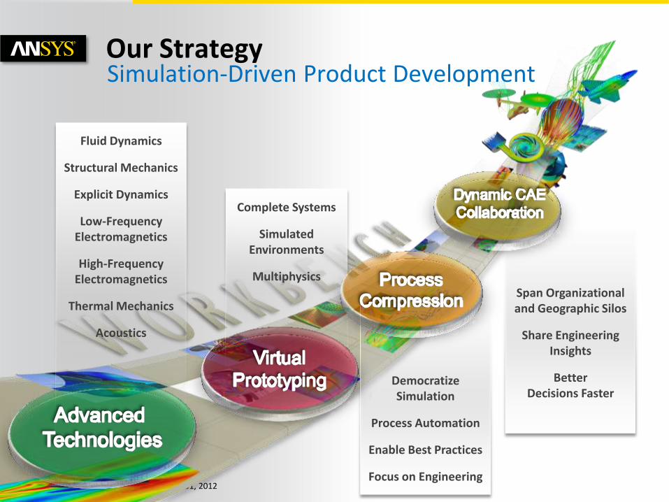
Simulation-Driven Product Development
Democratize Simulation
Process Automation
Enable Best Practices
Focus on Engineering
Complete Systems
Simulated Environments
Multiphysics
Fluid Dynamics
Structural Mechanics
Explicit Dynamics
Low-Frequency Electromagnetics
High-Frequency Electromagnetics
Thermal Mechanics
Acoustics
Span Organizational and Geographic Silos
Share Engineering Insights
Better Decisions Faster
Our Strategy
© 2011 ANSYS, Inc. October 31, 2012 3
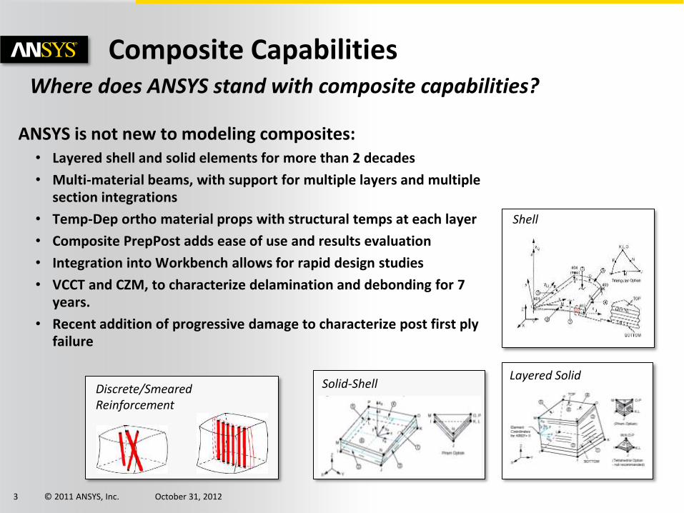
Composite Capabilities
Solid-Shell
Layered Solid
Shell
Discrete/Smeared Reinforcement
ANSYS is not new to modeling composites: • Layered shell and solid elements for more than 2 decades
• Multi-material beams, with support for multiple layers and multiple section integrations
• Temp-Dep ortho material props with structural temps at each layer
• Composite PrepPost adds ease of use and results evaluation
• Integration into Workbench allows for rapid design studies
• VCCT and CZM, to characterize delamination and debonding for 7 years.
• Recent addition of progressive damage to characterize post first ply failure
Where does ANSYS stand with composite capabilities?

© 2011 ANSYS, Inc. October 31, 2012 4
Highlight several focus area for this discussion:
• Allow for geometric design changes to model
• Make changes to layup, ply locations, and orientations
• Incorporate fluid/thermal loading directly from CFD
• Incorporate loading from external data or other simulations
• Solve structural simulations all off the same unified model
• Static (linear & non-linear)
• Buckling (linear & non-linear)
• Transient Dynamic
• Linear Dynamics
• Explicit (Bird Strike, Drop Test, Crash and Impact, etc.)
• Ease of post-processing of composite results
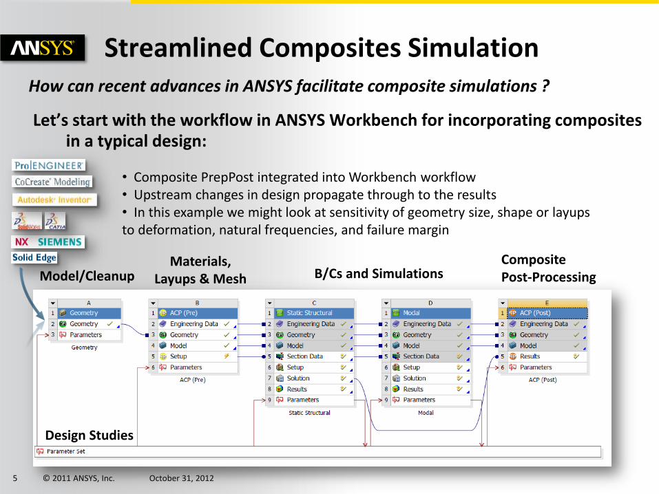
Streamlined Composites Simulation
© 2011 ANSYS, Inc. October 31, 2012 5
Let’s start with the workflow in ANSYS Workbench for incorporating composites in a typical design:
Streamlined Composites Simulation How can recent advances in ANSYS facilitate composite simulations ?
Materials, Layups & Mesh B/Cs and Simulations
Composite Post-Processing Model/Cleanup
Design Studies
• Composite PrepPost integrated into Workbench workflow • Upstream changes in design propagate through to the results • In this example we might look at sensitivity of geometry size, shape or layups to deformation, natural frequencies, and failure margin
© 2011 ANSYS, Inc. October 31, 2012 6
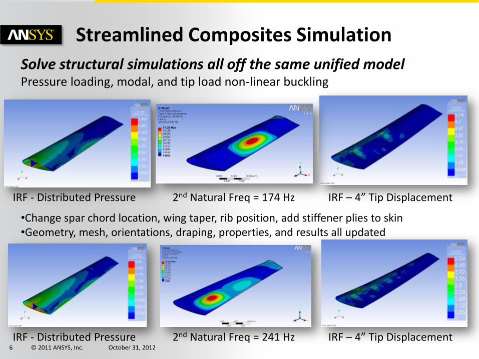
Streamlined Composites Simulation
Solve structural simulations all off the same unified model Pressure loading, modal, and tip load non-linear buckling
•Change spar chord location, wing taper, rib position, add stiffener plies to skin •Geometry, mesh, orientations, draping, properties, and results all updated
IRF - Distributed Pressure 2nd Natural Freq = 174 Hz IRF – 4” Tip Displacement
IRF - Distributed Pressure 2nd Natural Freq = 241 Hz IRF – 4” Tip Displacement

© 2011 ANSYS, Inc. October 31, 2012 7
Easy Ply Boundary Changes

© 2011 ANSYS, Inc. October 31, 2012 8
What-if Studies and DOE
Perform what-if studies Here we look at how the tip deflection and 2nd natural frequency change with the 1st rib spanwise location.
Create response surfaces for optimization
© 2011 ANSYS, Inc. October 31, 2012 9
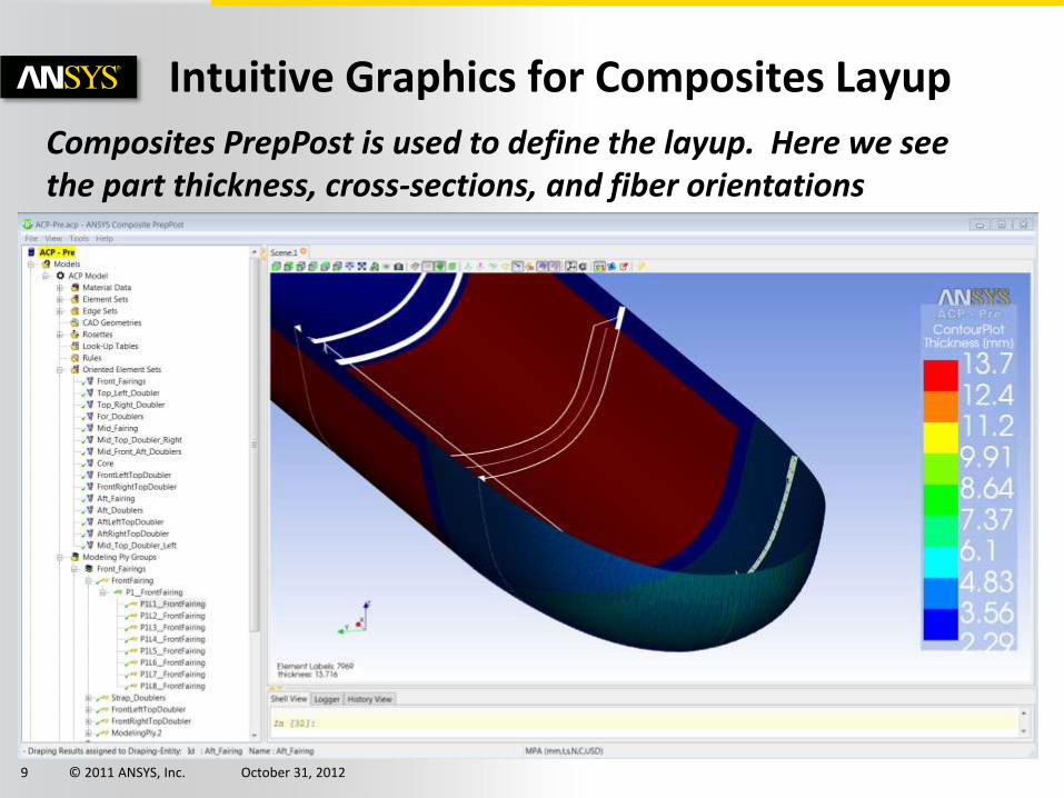
Intuitive Graphics for Composites Layup
Composites PrepPost is used to define the layup. Here we see the part thickness, cross-sections, and fiber orientations
© 2011 ANSYS, Inc. October 31, 2012 10
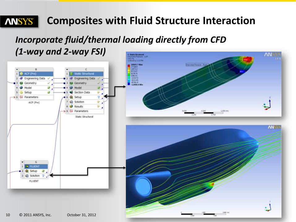
Composites with Fluid Structure Interaction
Incorporate fluid/thermal loading directly from CFD (1-way and 2-way FSI)
© 2011 ANSYS, Inc. October 31, 2012 11
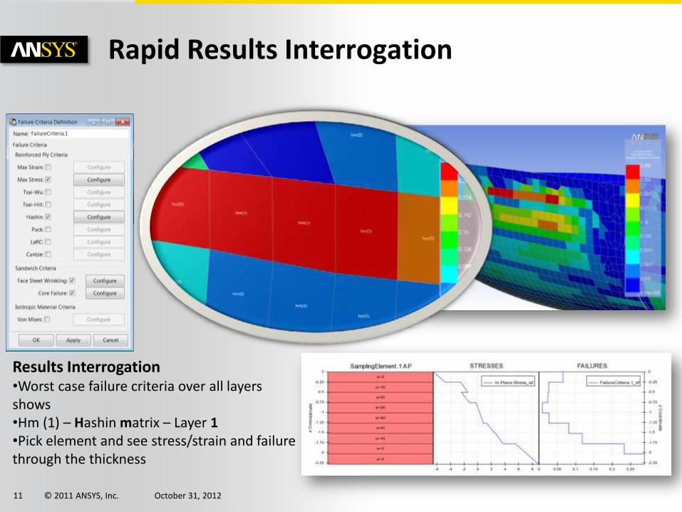
Rapid Results Interrogation
Results Interrogation •Worst case failure criteria over all layers shows •Hm (1) – Hashin matrix – Layer 1 •Pick element and see stress/strain and failure through the thickness

© 2011 ANSYS, Inc. October 31, 2012 12
Incorporate Loading from 3rd Party Output
Data Mapping •Pressure •Temperature •Heat Transfer •Thickness •Displacements

© 2011 ANSYS, Inc. October 31, 2012 13
Complex Model with Multiple Loadings
Radome Case Study
Connections
Deformations from FSI
Failure Criteria
© 2011 ANSYS, Inc. October 31, 2012 14
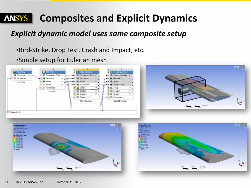
Composites and Explicit Dynamics
Explicit dynamic model uses same composite setup
•Bird-Strike, Drop Test, Crash and Impact, etc.
•Simple setup for Eulerian mesh
© 2011 ANSYS, Inc. October 31, 2012 15
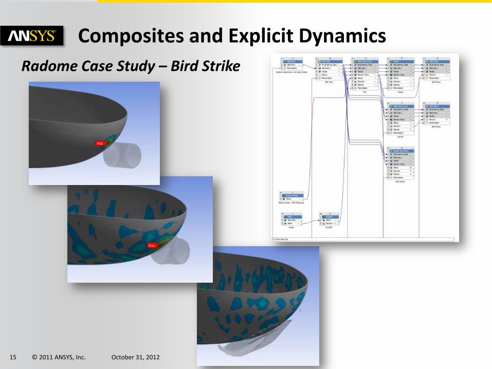
Composites and Explicit Dynamics
Radome Case Study – Bird Strike
© 2011 ANSYS, Inc. October 31, 2012 16
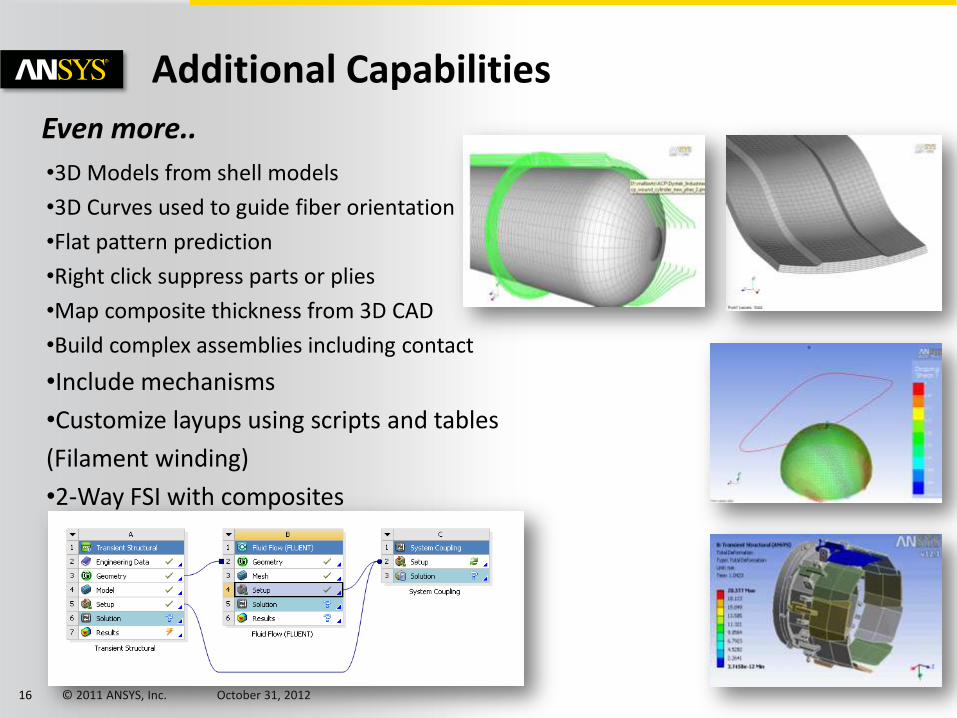
Additional Capabilities
Even more.. •3D Models from shell models
•3D Curves used to guide fiber orientation
•Flat pattern prediction
•Right click suppress parts or plies
•Map composite thickness from 3D CAD
•Build complex assemblies including contact
•Include mechanisms
•Customize layups using scripts and tables
(Filament winding)
•2-Way FSI with composites

© 2011 ANSYS, Inc. October 31, 2012 17
R14.5 Solid Composite Workflow
•Build 3D Solid Composites Easily
•Incorporate into models with
connections and contact
•Update model, suppress plies with a
button click

© 2011 ANSYS, Inc. October 31, 2012 18
R14.5 Solid Composite Workflow
Shell Model Automatic Solid Model
Solid Model Passes to ANSYS Mechanical
© 2011 ANSYS, Inc. October 31, 2012 19
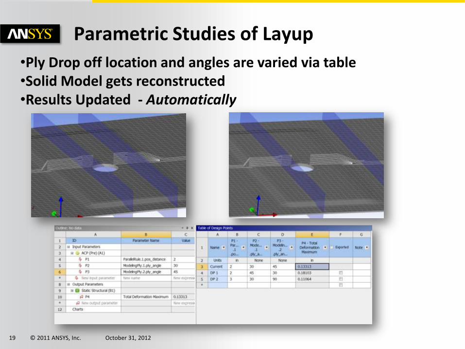
Parametric Studies of Layup
•Ply Drop off location and angles are varied via table •Solid Model gets reconstructed •Results Updated - Automatically
© 2011 ANSYS, Inc. October 31, 2012 20
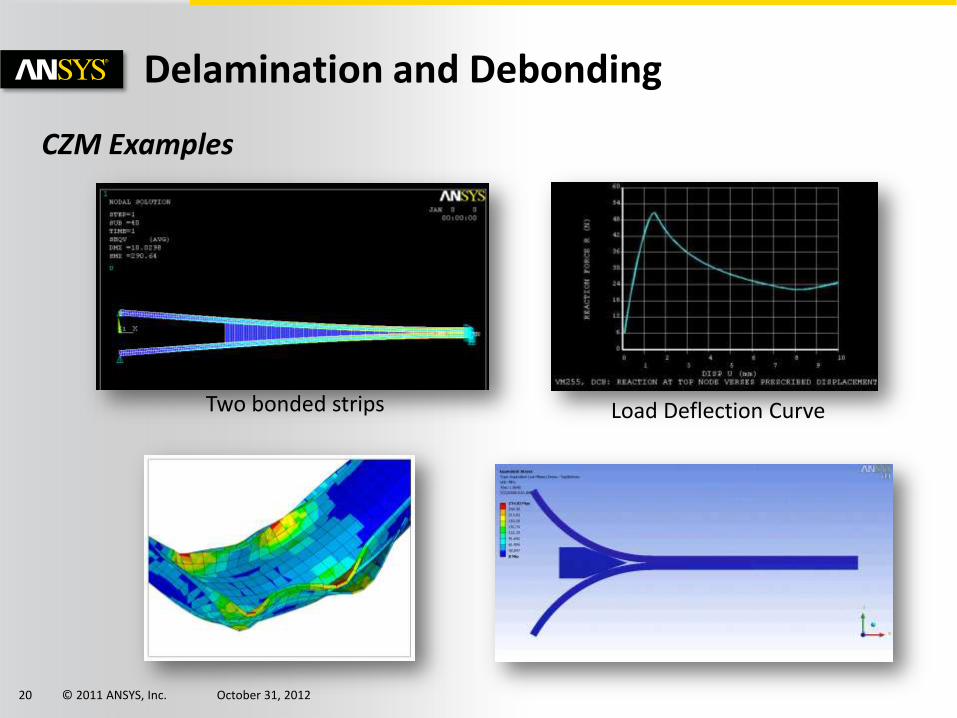
Delamination and Debonding
CZM Examples
Load Deflection Curve Two bonded strips
© 2011 ANSYS, Inc. October 31, 2012 21
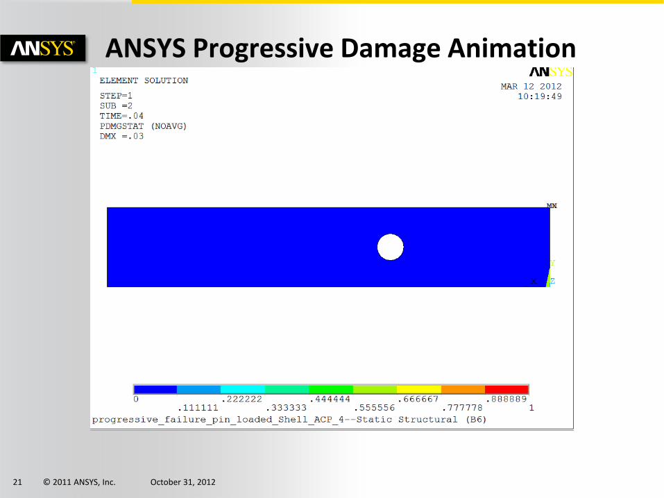
ANSYS Progressive Damage Animation
© 2011 ANSYS, Inc. October 31, 2012 22
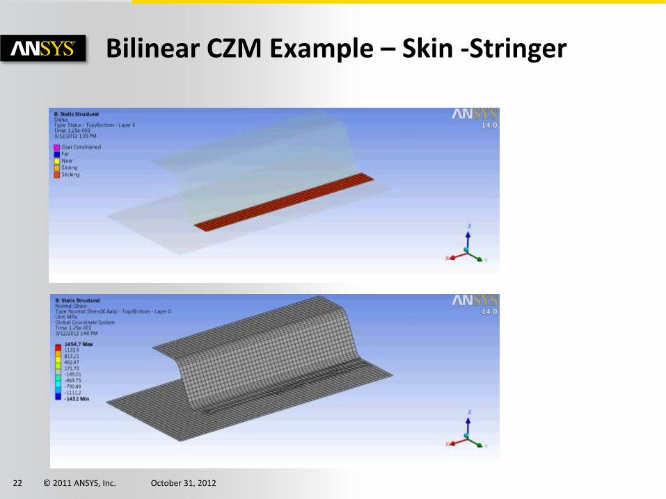
Bilinear CZM Example – Skin -Stringer

© 2011 ANSYS, Inc. October 31, 2012 23
VCCT-Based Crack Growth Simulation
VCCT Examples
Results from published paper
ANSYS R14
Mixed Mode Bending (MMB) Specimen
Reference: Progressive crack growth analysis using interface element based on the virtual crack closure technique by De Xiea and Sherrill B. Biggers Jr. Finite Elements in Analysis and Design 42 (2006) 977 – 984

© 2011 ANSYS, Inc. October 31, 2012 24
VCCT-Based Crack Growth Simulation
VCCT Examples Mixed Mode Bending (MMB) Specimen
Reference: Progressive crack growth analysis using interface element based on the virtual crack closure technique by De Xiea and Sherrill B. Biggers Jr. Finite Elements in Analysis and Design 42 (2006) 977 – 984

© 2011 ANSYS, Inc. October 31, 2012 25
Summary
• Composites simulations with ANSYS
• Setup model one time, make changes to examine what if
• Look at sensitivities of design changes
• Investigate damage tolerance to flaws
• Investigate post first ply failure
• Simple “Drag-and-Drop” Multiphysics
• Easily incorporate thermal, fluids, and pressures
• Additional capability to import 3rd party data
• Improve design fidelity by optimization
• One single framework – ANSYS Workbench
© 2011 ANSYS, Inc. October 31, 2012 26
Thank You!