Embed Size (px)
Citation preview
© ika 2018 · All rights reserved2018/11/07Slide No. 1#150 · 18rm0008.pptx
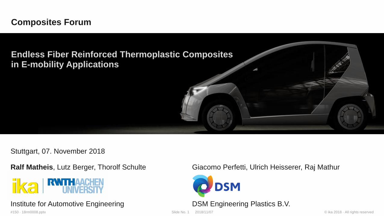
Stuttgart, 07. November 2018
Ralf Matheis, Lutz Berger, Thorolf Schulte
Endless Fiber Reinforced Thermoplastic Composites in E-mobility Applications
Institute for Automotive Engineering
Giacomo Perfetti, Ulrich Heisserer, Raj Mathur
DSM Engineering Plastics B.V.
Composites Forum
© ika 2018 · All rights reserved2018/11/07Slide No. 2#150 · 18rm0008.pptx
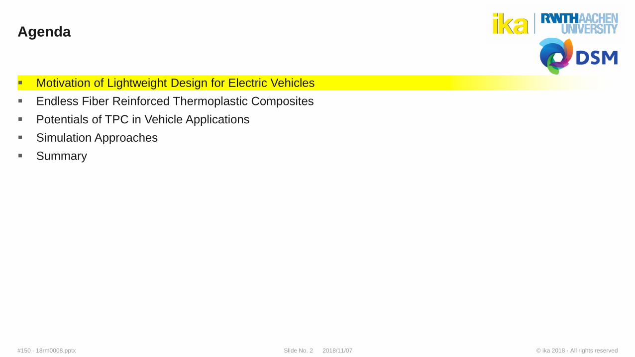
Agenda
Motivation of Lightweight Design for Electric Vehicles
Endless Fiber Reinforced Thermoplastic Composites
Potentials of TPC in Vehicle Applications
Simulation Approaches
Summary
© ika 2018 · All rights reserved2018/11/07Slide No. 5#150 · 18rm0008.pptx
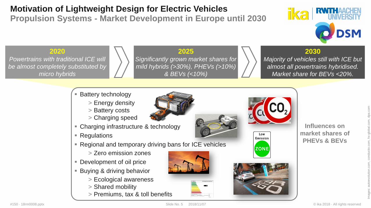
Motivation of Lightweight Design for Electric VehiclesPropulsion Systems - Market Development in Europe until 2030
2020Powertrains with traditional ICE will
be almost completely substituted by
micro hybrids
2025Significantly grown market shares for
mild hybrids (>30%), PHEVs (>10%)
& BEVs (<10%)
2030Majority of vehicles still with ICE but
almost all powertrains hybridised.
Market share for BEVs <20%.
Battery technology
> Energy density
> Battery costs
> Charging speed
Charging infrastructure & technology
Regulations
Regional and temporary driving bans for ICE vehicles
> Zero emission zones
Development of oil price
Buying & driving behavior
> Ecological awareness
> Shared mobility
> Premiums, tax & toll benefits
Influences on
market shares of
PHEVs & BEVs
Images: auto
evolu
tio
n.c
om
, conductix.c
om
, hx-g
lobal.com
, dpa.c
om
© ika 2018 · All rights reserved2018/11/07Slide No. 6#150 · 18rm0008.pptx
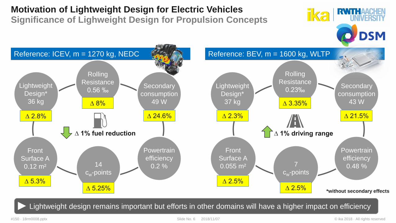
Motivation of Lightweight Design for Electric VehiclesSignificance of Lighweight Design for Propulsion Concepts
Lightweight
Design*
37 kg
Rolling
Resistance
0.23‰
Front
Surface A
0.055 m² 7
cw-points
Secondary
consumption
43 W
Powertrain
efficiency
0.48 %
∆ 1% driving range
Reference: BEV, m = 1600 kg, WLTP
Lightweight
Design*
36 kg
Rolling
Resistance
0.56 ‰
Front
Surface A
0.12 m² 14
cw-points
Secondary
consumption
49 W
Powertrain
efficiency
0.2 %
∆ 1% fuel reduction
Reference: ICEV, m = 1270 kg, NEDC
Lightweight design remains important but efforts in other domains will have a higher impact on efficiency
∆ 2.8%
∆ 5.3% ∆ 5.25%
∆ 24.6%
∆ 8%
∆ 2.3%
∆ 3.35%
∆ 21.5%
∆ 2.5% ∆ 2.5%
*without secondary effects
© ika 2018 · All rights reserved2018/11/07Slide No. 7#150 · 18rm0008.pptx
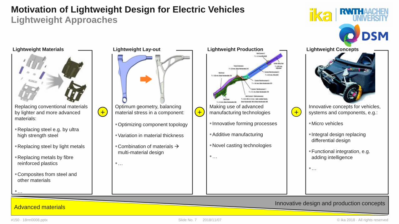
Advanced materialsInnovative design and production concepts
Innovative concepts for vehicles,
systems and components, e.g.:
Micro vehicles
Integral design replacing
differential design
Functional integration, e.g.
adding intelligence
…
Optimum geometry, balancing
material stress in a component:.
Optimizing component topology
Variation in material thickness
Combination of materials
multi-material design
…
Lightweight Lay-out
Making use of advanced
manufacturing technologies
Innovative forming processes
Additive manufacturing
Novel casting technologies
…
Lightweight Production
Replacing conventional materials
by lighter and more advanced
materials:
Replacing steel e.g. by ultra
high strength steel
Replacing steel by light metals
Replacing metals by fibre
reinforced plastics
Composites from steel and
other materials
…
Lightweight Materials
+ + +
Motivation of Lightweight Design for Electric VehiclesLightweight Approaches
Lightweight Concepts
© ika 2018 · All rights reserved2018/11/07Slide No. 8#150 · 18rm0008.pptx
Agenda
Introduction ika
Motivation of Lightweight Design for Electric Vehicles
Endless Fiber Reinforced Thermoplastic Composites
Potentials of TPC in Vehicle Applications
Simulation Approaches
Summary
© ika 2018 · All rights reserved2018/11/07Slide No. 9#150 · 18rm0008.pptx
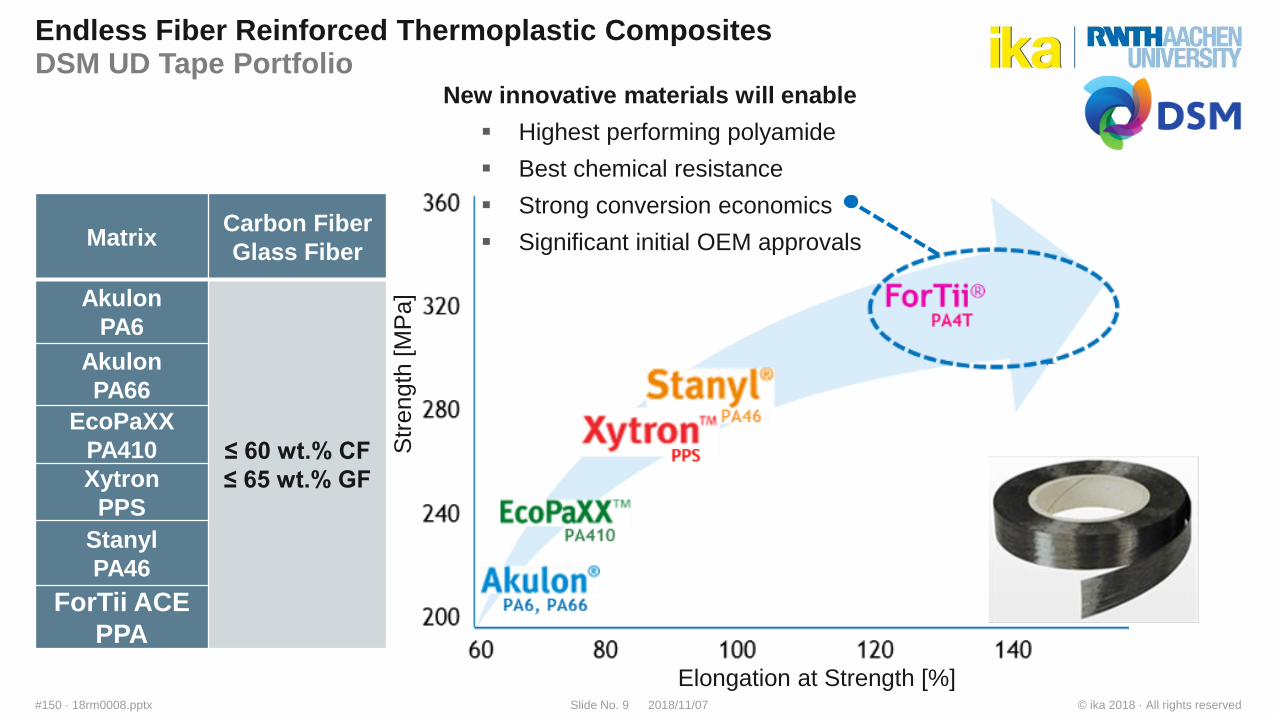
MatrixCarbon Fiber
Glass Fiber
Akulon
PA6
≤ 60 wt.% CF
≤ 65 wt.% GF
Akulon
PA66
EcoPaXX
PA410
Xytron
PPS
Stanyl
PA46
ForTii ACE
PPA
Endless Fiber Reinforced Thermoplastic CompositesDSM UD Tape Portfolio
New innovative materials will enable
Highest performing polyamide
Best chemical resistance
Strong conversion economics
Significant initial OEM approvals
Str
ength
[M
Pa]
Elongation at Strength [%]
© ika 2018 · All rights reserved2018/11/07Slide No. 10#150 · 18rm0008.pptx
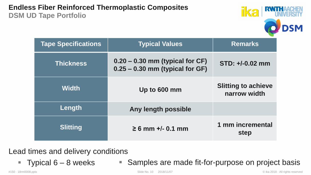
Endless Fiber Reinforced Thermoplastic CompositesDSM UD Tape Portfolio
Lead times and delivery conditions
Typical 6 – 8 weeks
Tape Specifications Typical Values Remarks
Thickness 0.20 – 0.30 mm (typical for CF)
0.25 – 0.30 mm (typical for GF)STD: +/-0.02 mm
Width Up to 600 mmSlitting to achieve
narrow width
Length Any length possible
Slitting ≥ 6 mm +/- 0.1 mm1 mm incremental
step
Samples are made fit-for-purpose on project basis
© ika 2018 · All rights reserved2018/11/07Slide No. 11#150 · 18rm0008.pptx
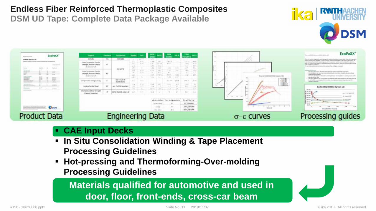
Endless Fiber Reinforced Thermoplastic CompositesDSM UD Tape: Complete Data Package Available
CAE Input Decks
In Situ Consolidation Winding & Tape Placement
Processing Guidelines
Hot-pressing and Thermoforming-Over-molding
Processing Guidelines
Materials qualified for automotive and used in
door, floor, front-ends, cross-car beam
© ika 2018 · All rights reserved2018/11/07Slide No. 12#150 · 18rm0008.pptx
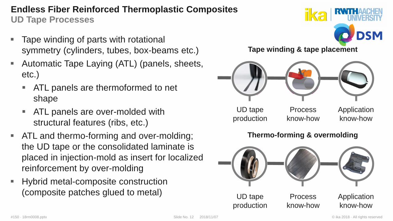
Endless Fiber Reinforced Thermoplastic CompositesUD Tape Processes
Tape winding of parts with rotational
symmetry (cylinders, tubes, box-beams etc.)
Automatic Tape Laying (ATL) (panels, sheets,
etc.)
ATL panels are thermoformed to net
shape
ATL panels are over-molded with
structural features (ribs, etc.)
ATL and thermo-forming and over-molding;
the UD tape or the consolidated laminate is
placed in injection-mold as insert for localized
reinforcement by over-molding
Hybrid metal-composite construction
(composite patches glued to metal)
Tape winding & tape placement
Thermo-forming & overmolding
UD tape
production
Process
know-how
Application
know-how
UD tape
production
Process
know-how
Application
know-how
© ika 2018 · All rights reserved2018/11/07Slide No. 13#150 · 18rm0008.pptx
Agenda
Introduction ika
Motivation of Lightweight Design for Electric Vehicles
Endless Fiber Reinforced Thermoplastic Composites
Potentials of TPC in Vehicle Applications
Simulation Approaches
Summary
© ika 2018 · All rights reserved2018/11/07Slide No. 14#150 · 18rm0008.pptx
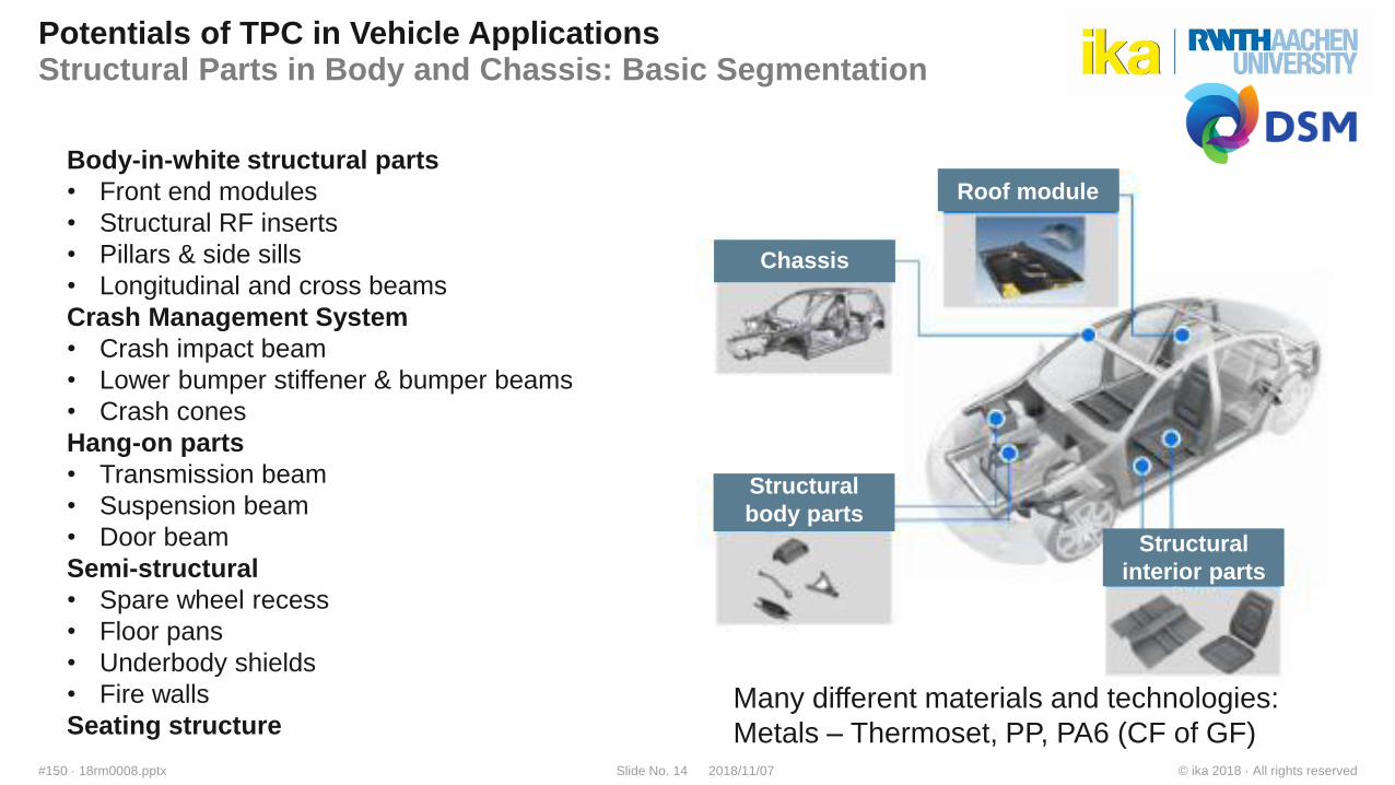
Potentials of TPC in Vehicle ApplicationsStructural Parts in Body and Chassis: Basic Segmentation
Body-in-white structural parts
• Front end modules
• Structural RF inserts
• Pillars & side sills
• Longitudinal and cross beams
Crash Management System
• Crash impact beam
• Lower bumper stiffener & bumper beams
• Crash cones
Hang-on parts
• Transmission beam
• Suspension beam
• Door beam
Semi-structural
• Spare wheel recess
• Floor pans
• Underbody shields
• Fire walls
Seating structureMany different materials and technologies:
Metals – Thermoset, PP, PA6 (CF of GF)
Chassis
Roof module
Structural
body parts
Structural
interior parts
© ika 2018 · All rights reserved2018/11/07Slide No. 15#150 · 18rm0008.pptx
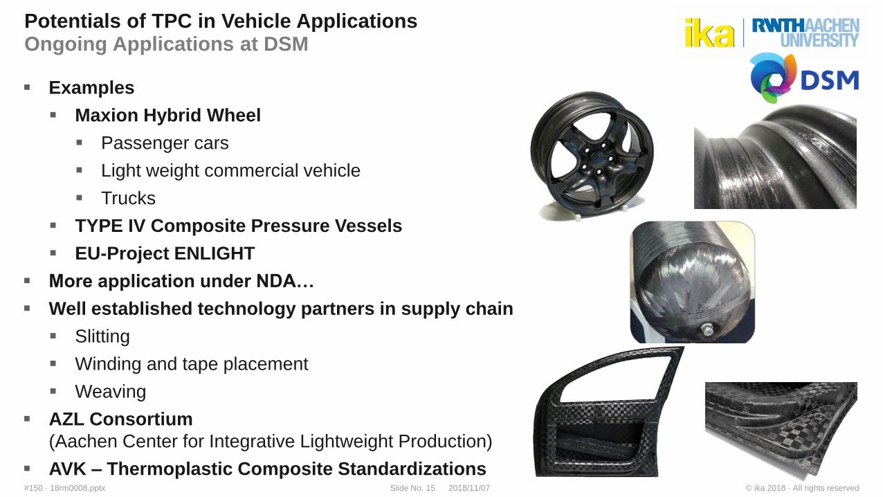
Potentials of TPC in Vehicle ApplicationsOngoing Applications at DSM
Examples
Maxion Hybrid Wheel
Passenger cars
Light weight commercial vehicle
Trucks
TYPE IV Composite Pressure Vessels
EU-Project ENLIGHT
More application under NDA…
Well established technology partners in supply chain
Slitting
Winding and tape placement
Weaving
AZL Consortium
(Aachen Center for Integrative Lightweight Production)
AVK – Thermoplastic Composite Standardizations

© ika 2018 · All rights reserved2018/11/07Slide No. 16#150 · 18rm0008.pptx
Potentials of TPC in Vehicle ApplicationsProject ENLIGHT
ENLIGHT - Enhanced Lightweight Design
(Research project funded by the European Union)
Sustainable lightweight design of vehicle body
modules for series production in future electric
vehicles (ca. 50.000/year, horizon: 8 – 12 years)
Application of innovative lightweight materials
Significant mass reduction compared to metal intensive
lightweight design
Funded by
the Seventh Framework
Programme
of the European Union
© ika 2018 · All rights reserved2018/11/07Slide No. 17#150 · 18rm0008.pptx
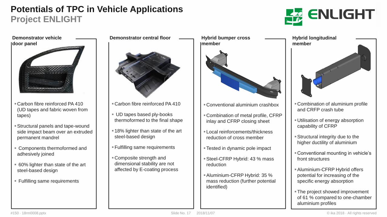
Potentials of TPC in Vehicle ApplicationsProject ENLIGHT
Carbon fibre reinforced PA 410
(UD tapes and fabric woven from
tapes)
Structural panels and tape-wound
side impact beam over an extruded
permanent mandrel
Components thermoformed and
adhesively joined
60% lighter than state of the art
steel-based design
Fulfilling same requirements
Demonstrator vehicle
door panel
Carbon fibre reinforced PA 410
UD tapes based ply-books
thermoformed to the final shape
18% lighter than state of the art
steel-based design
Fulfilling same requirements
Composite strength and
dimensional stability are not
affected by E-coating process
Demonstrator central floor
Conventional aluminium crashbox
Combination of metal profile, CFRP
inlay and CFRP closing sheet
Local reinforcements/thickness
reduction of cross member
Tested in dynamic pole impact
Steel-CFRP Hybrid: 43 % mass
reduction
Aluminium-CFRP Hybrid: 35 %
mass reduction (further potential
identified)
Hybrid bumper cross
member
Combination of aluminium profile
and CRFP crash tube
Utilisation of energy absorption
capability of CFRP
Structural integrity due to the
higher ductility of aluminium
Conventional mounting in vehicle’s
front structures
Aluminium-CFRP Hybrid offers
potential for increasing of the
specific energy absorption
The project showed improvement
of 61 % compared to one-chamber
aluminium profiles
Hybrid longitudinal
member
© ika 2018 · All rights reserved2018/11/07Slide No. 18#150 · 18rm0008.pptx
Agenda
Introduction ika
Motivation of Lightweight Design for Electric Vehicles
Endless Fiber Reinforced Thermoplastic Composites
Potentials of TPC in Vehicle Applications
Simulation Approaches
Summary
© ika 2018 · All rights reserved2018/11/07Slide No. 19#150 · 18rm0008.pptx
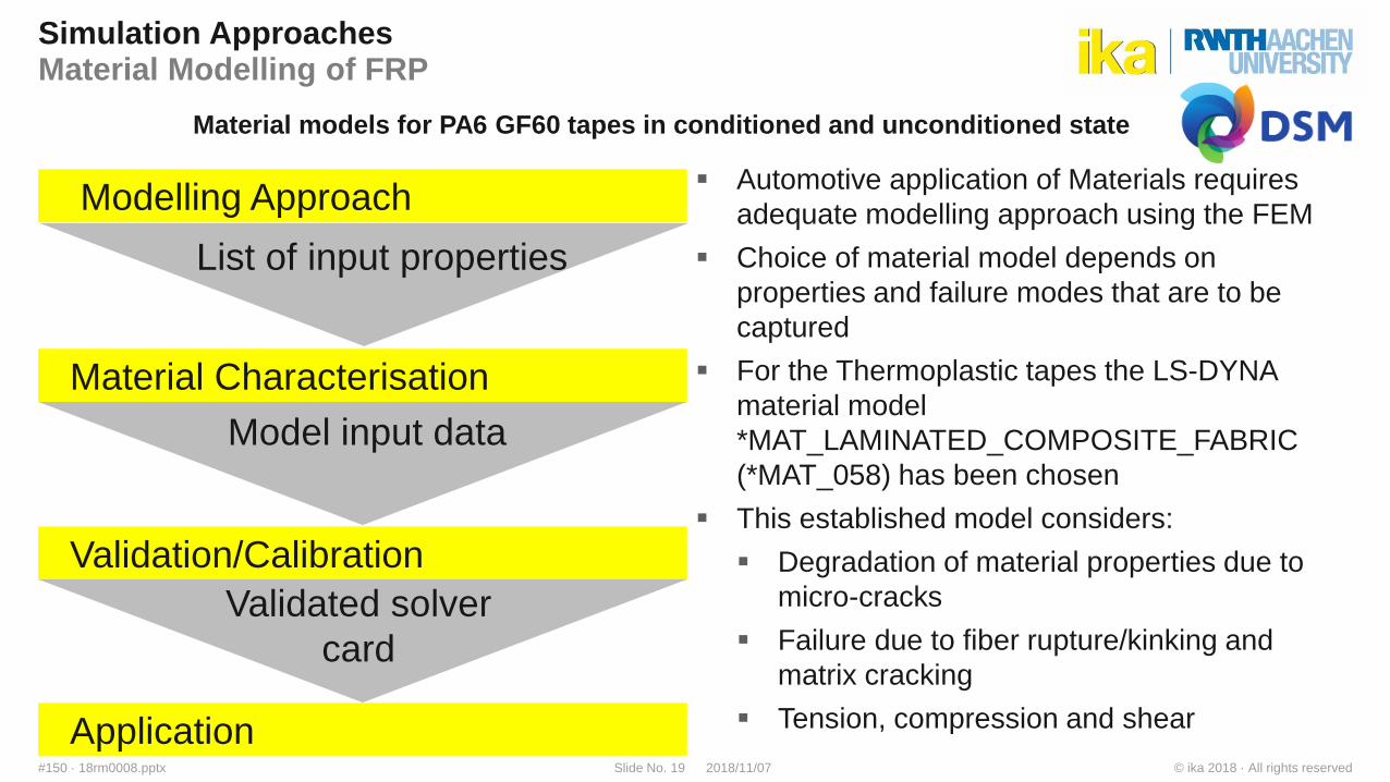
Simulation ApproachesMaterial Modelling of FRP
Automotive application of Materials requires
adequate modelling approach using the FEM
Choice of material model depends on
properties and failure modes that are to be
captured
For the Thermoplastic tapes the LS-DYNA
material model
*MAT_LAMINATED_COMPOSITE_FABRIC
(*MAT_058) has been chosen
This established model considers:
Degradation of material properties due to
micro-cracks
Failure due to fiber rupture/kinking and
matrix cracking
Tension, compression and shear
Modelling Approach
List of input properties
Material Characterisation
Model input data
Validation/Calibration
Validated solver
card
Application
Material models for PA6 GF60 tapes in conditioned and unconditioned state
© ika 2018 · All rights reserved2018/11/07Slide No. 20#150 · 18rm0008.pptx
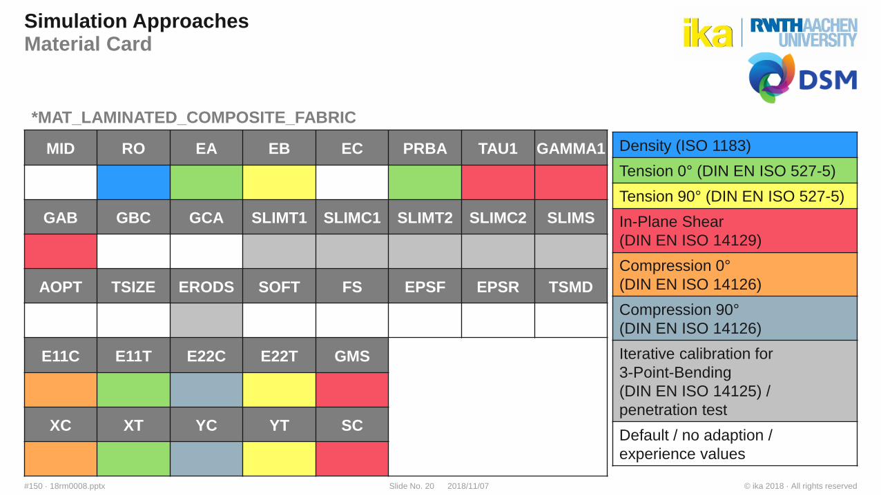
Simulation ApproachesMaterial Card
MID RO EA EB EC PRBA TAU1 GAMMA1
GAB GBC GCA SLIMT1 SLIMC1 SLIMT2 SLIMC2 SLIMS
AOPT TSIZE ERODS SOFT FS EPSF EPSR TSMD
E11C E11T E22C E22T GMS
XC XT YC YT SC
*MAT_LAMINATED_COMPOSITE_FABRIC
Density (ISO 1183)
Tension 0° (DIN EN ISO 527-5)
Tension 90° (DIN EN ISO 527-5)
In-Plane Shear
(DIN EN ISO 14129)
Compression 0°
(DIN EN ISO 14126)
Compression 90°
(DIN EN ISO 14126)
Iterative calibration for
3-Point-Bending
(DIN EN ISO 14125) /
penetration test
Default / no adaption /
experience values
© ika 2018 · All rights reserved2018/11/07Slide No. 21#150 · 18rm0008.pptx
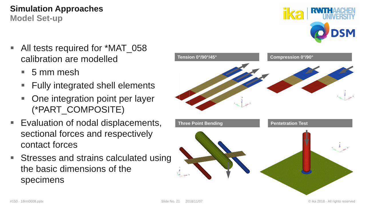
Simulation ApproachesModel Set-up
All tests required for *MAT_058
calibration are modelled
5 mm mesh
Fully integrated shell elements
One integration point per layer
(*PART_COMPOSITE)
Evaluation of nodal displacements,
sectional forces and respectively
contact forces
Stresses and strains calculated using
the basic dimensions of the
specimens
Tension 0°/90°/45° Compression 0°/90°
Three Point Bending Pentetration Test
© ika 2018 · All rights reserved2018/11/07Slide No. 22#150 · 18rm0008.pptx
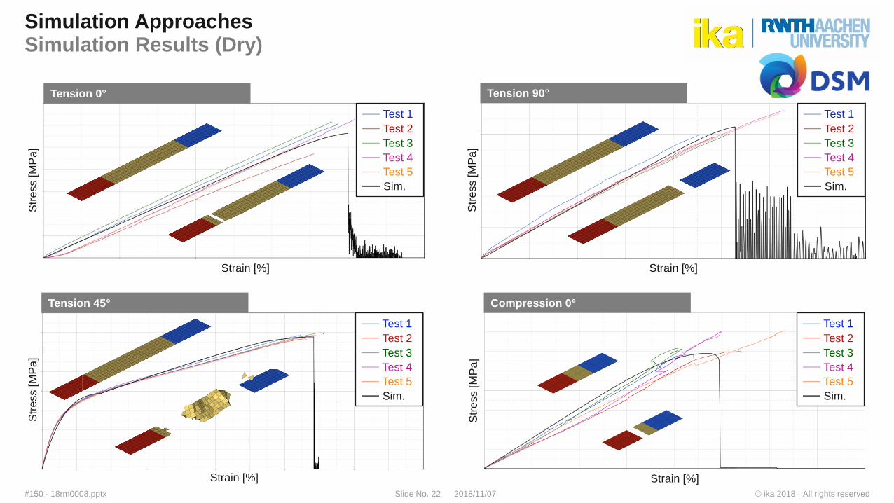
Simulation ApproachesSimulation Results (Dry)
Test 1
Test 2
Test 3
Test 4
Test 5
Sim.
Test 1
Test 2
Test 3
Test 4
Test 5
Sim.
Test 1
Test 2
Test 3
Test 4
Test 5
Sim.
Test 1
Test 2
Test 3
Test 4
Test 5
Sim.
Str
ess [M
Pa
]
Str
ess [M
Pa
]
Strain [%]
Str
ess [M
Pa
]
Strain [%]S
tre
ss [M
Pa
]Strain [%]
Strain [%]
Compression 0°
Tension 0°
Tension 45°
Tension 90°
© ika 2018 · All rights reserved2018/11/07Slide No. 23#150 · 18rm0008.pptx
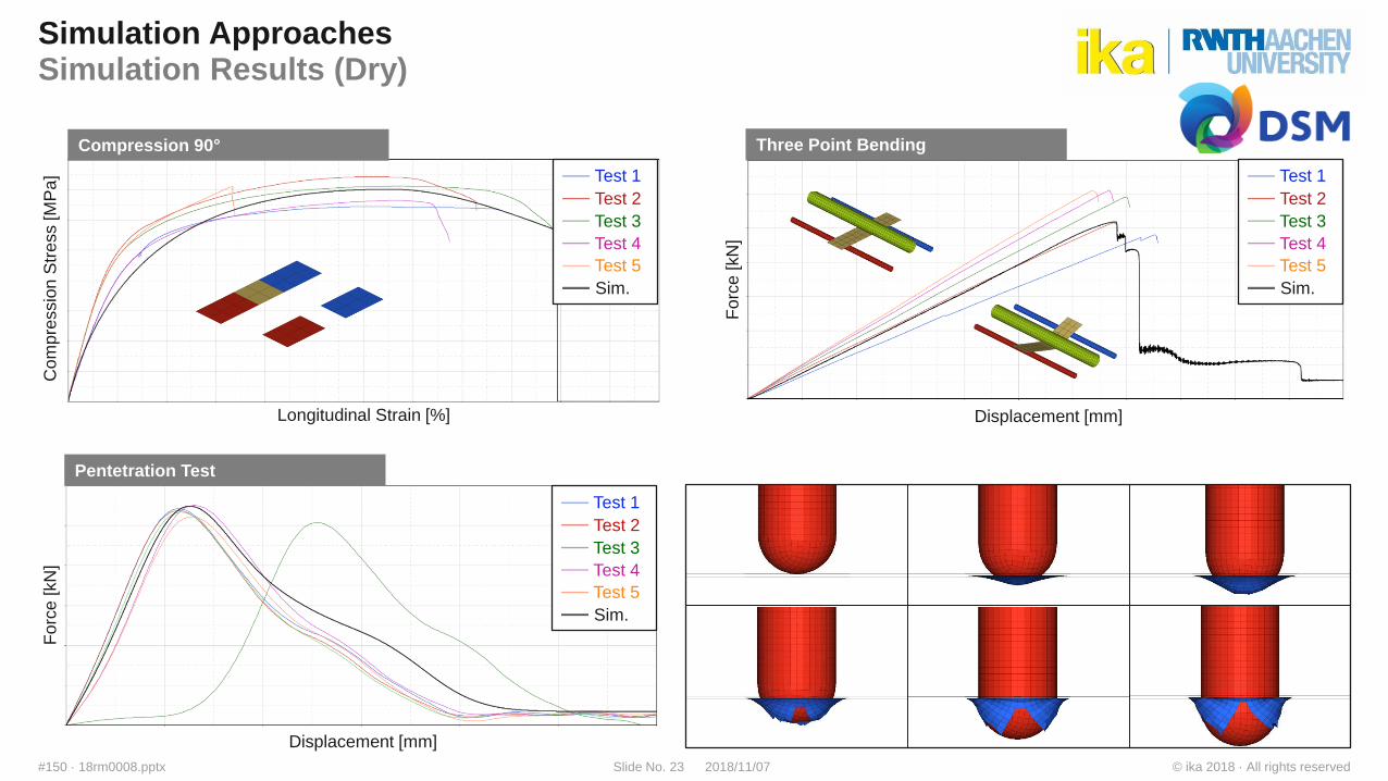
Simulation ApproachesSimulation Results (Dry)
Test 1
Test 2
Test 3
Test 4
Test 5
Sim.
Test 1
Test 2
Test 3
Test 4
Test 5
Sim.
Test 1
Test 2
Test 3
Test 4
Test 5
Sim.
Com
pre
ssio
nS
tre
ss [M
Pa
]
Longitudinal Strain [%]
Fo
rce [kN
]
Displacement [mm]
Fo
rce [kN
]
Displacement [mm]
Compression 90°
Pentetration Test
Three Point Bending
© ika 2018 · All rights reserved2018/11/07Slide No. 24#150 · 18rm0008.pptx
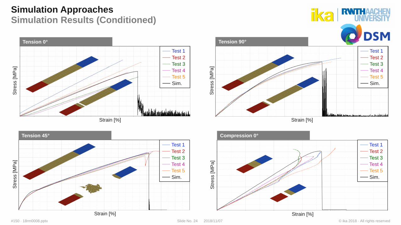
Simulation ApproachesSimulation Results (Conditioned)
Test 1
Test 2
Test 3
Test 4
Test 5
Sim.
Test 1
Test 2
Test 3
Test 4
Test 5
Sim.
Test 1
Test 2
Test 3
Test 4
Test 5
Sim.
Test 1
Test 2
Test 3
Test 4
Test 5
Sim.
Str
ess [M
Pa
]
Str
ess [M
Pa
]
Strain [%]
Str
ess [M
Pa
]
Strain [%]S
tre
ss [M
Pa
]Strain [%]
Strain [%]
Compression 0°
Tension 0°
Tension 45°
Tension 90°
© ika 2018 · All rights reserved2018/11/07Slide No. 25#150 · 18rm0008.pptx
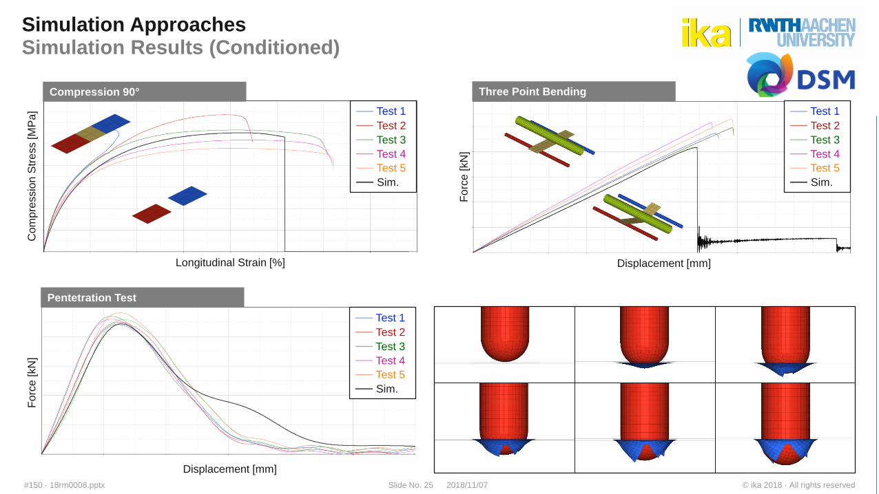
Simulation ApproachesSimulation Results (Conditioned)
Test 1
Test 2
Test 3
Test 4
Test 5
Sim.
Test 1
Test 2
Test 3
Test 4
Test 5
Sim.
Test 1
Test 2
Test 3
Test 4
Test 5
Sim.
Com
pre
ssio
nS
tre
ss [M
Pa
]
Longitudinal Strain [%]
Fo
rce [kN
]
Displacement [mm]
Fo
rce [kN
]
Displacement [mm]
Compression 90°
Pentetration Test
Three Point Bending
© ika 2018 · All rights reserved2018/11/07Slide No. 26#150 · 18rm0008.pptx
Agenda
Introduction ika
Motivation of Lightweight Design for Electric Vehicles
Endless Fiber Reinforced Thermoplastic Composites
Potentials of TPC in Vehicle Applications
Simulation Approaches
Summary
© ika 2018 · All rights reserved2018/11/07Slide No. 27#150 · 18rm0008.pptx
Summary
Lightweight will remain a key driver for vehicle innovation
With regard of the energy efficiency of electric vehicles lightweight design plays an important roll
Other domains will have an higher impact than they used to have for vehicles with combustion
engines
Endless fiber reinforced products offer high lightweight potential for to load appropriate design
Several endless fiber reinforced tapes for automotive application available by DSM
Various application fields in BiW, hang-on parts, semi-structurals and seating
Automotive application of materials requires adequate modelling approach using the FEM
Material models for PA6 GF60 tapes in conditioned and unconditioned state are available for the
solver LS-DYNA
© ika 2018 · All rights reserved2018/11/07Slide No. 28#150 · 18rm0008.pptx
Phone
Fax
Internet www.ika.rwth-aachen.de
Institute for Automotive Engineering (ika)
RWTH Aachen University
Steinbachstr. 7
52074 Aachen
Germany
Contact
Dipl.-Ing. Ralf Matheis
+49 241 88 61121
Phone
Internet www.dsmep.com
DSM Engineering Plastics Europe
Urmonderbaan 22
6167 RD GELEEN
Netherlands
Giacomo Perfetti, PhD
+31 6 83649747