Embed Size (px)
Citation preview
Composites Science and Technology 68 (2008) 2653–2662
Contents lists available at ScienceDirect
Composites Science and Technology
journal homepage: www.elsevier .com/ locate/compsci tech
Experimental optimization of the impact energy absorption of epoxy–carbonlaminates through controlled delamination
Alessandro Pegoretti *, Ivan Cristelli, Claudio MigliaresiDepartment of Materials Engineering and Industrial Technologies and INSTM Research Unit, University of Trento, via Mesiano 77, 38100 Trento, Italy
a r t i c l e i n f o a b s t r a c t
Article history:Received 26 February 2008Accepted 11 April 2008Available online 4 May 2008
Keywords:A. Layered structuresB. Impact behaviourB. DelaminationB. Fracture toughnessInterleaving
0266-3538/$ - see front matter � 2008 Elsevier Ltd. Adoi:10.1016/j.compscitech.2008.04.036
* Corresponding author. Tel.: +39 0461 882452; faxE-mail address: [email protected] (A. P
In this paper, the correlation between interlaminar fracture toughness and impact energy absorption forthe fracture of epoxy–carbon laminates was studied. Carbon fibres–epoxy cross-ply prepreg layers wereinterleaved with thin (26 lm) poly(ethylene-terephthalate) (PET) films. Before the composite prepara-tion, circular holes 1 mm in diameter were drilled in the PET films at several densities (from 0 up to44 holes/cm2) in order to selectively increase the interlaminar contact area between the epoxy–carbonlaminae. In this way, the interlaminar contact area was gradually varied from 0%, corresponding to thecase in which non-perforated PET films were used, up to 100% in the case of non-interleaved laminates.The Mode I interlaminar fracture toughness of the resulting laminates was determined according to theASTM D-5528-01 standard test method on double cantilever beam (DCB) specimens. The critical values ofthe strain energy release rate determined at the point at which the load versus opening displacementcurve becomes non-linear (GIC,NL) resulted to vary from 40 up to 260 J/m2, depending on the interlaminarcontact area. All the laminates were then characterized by three point bending tests performed bothunder quasi-static (5 mm/min) and impact (2 m/s) loading conditions. The elastic modulus of the lami-nates resulted to be practically independent of the level of interlaminar adhesion, while the bendingstrength decreased as the interlaminar fracture toughness decreased. The total energy to fracture evalu-ated under impact conditions showed a non-monotonic correlation with the interlaminar fracture tough-ness, reaching a maximum level in correspondence of a GIC,NL value of about 60 J/m2. At the same time,the ductility index, i.e. the ratio between the propagation and the initiation energies, evaluated by instru-mented Charpy impact tests, markedly increased as the interlaminar fracture toughness decreased.
� 2008 Elsevier Ltd. All rights reserved.
1. Introduction
The potential for weight savings with fiber-reinforced compos-ites renders these materials very attractive for several structuralapplication areas, which include military, aircraft, space, automo-tive, marine and sporting goods applications [1]. Many fibre-rein-forced composite materials offer a combination of specificmodulus and strength values that are either comparable to or bet-ter than many traditional metallic materials [1]. For some specificcomponents, such as bumpers, armours, helmets, disposable bar-rier shells, etc., the most important material requirement is thecapacity to absorb a large amount of mechanical energy under im-pact conditions before reaching complete fracture. Most compos-ites are brittle and so can only absorb energy in elasticdeformation and through damage mechanisms, and not via plasticdeformation [2]. There are five basic mechanical failure modes thatcan occur in a composite after the initial elastic deformation [3]: (i)fibre fracture, or, for aramids, defibrilation, (ii) resin crazing, micro-
ll rights reserved.
: +39 0461 881977.egoretti).
cracking and gross fracture, (iii) debonding between fibre and ma-trix, (iv) fibre pull out from the matrix, and (v) delamination ofadjacent plies in a laminate. In general, each of the above men-tioned mechanisms may contribute to the energy dissipation pro-cess under impact conditions. Delamination is the most importantdamage mechanism in impacted composite laminates [4]. When acomposite structure is impacted, delamination often occurs, whichseriously reduces the load bearing capacity of the laminate espe-cially under compressive loads [5]. Therefore, several methodshave been developed to improve the interlaminar strength andinterlaminar fracture toughness of composite laminates, such asmatrix toughening [6–9], through-thickness stitching [10–14],Z-pinning [15,16], interleaving [17–25] and short-fibre interlami-nar reinforcement [25]. Most of the above mentioned methodshave been reviewed by Kim and Mai [26], who also pointed outthe key role played by the fibre–matrix interfacial shear strengthin determining the interlaminar resistance of composite laminates.In fact, a marked improvement of the interlaminar resistance whenthe fibre–matrix adhesion increases is reported in several studies[27–30]. On the other hand, the improvement of damage resistanceand tolerance in interlaminar fracture is at the expenses of other
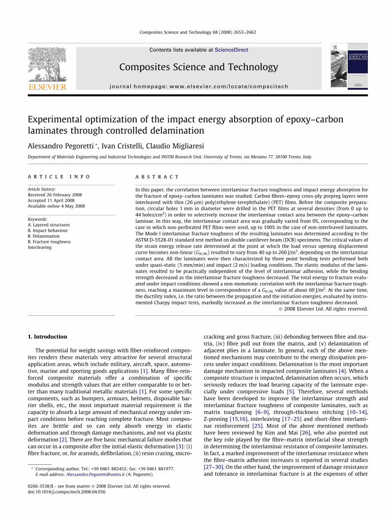
Fig. 1. Perforated PET foil: (a) optical micrograph and (b) schematic of the hole
2654 A. Pegoretti et al. / Composites Science and Technology 68 (2008) 2653–2662
important mechanical properties, such as the energy absorptionunder impact conditions [31] and the fatigue resistance. In fact,as the interlaminar strength increases the delamination damageis hindered, and the composite laminates tend to fracture in a morebrittle way under impact conditions. Hong and Liu [32] showedthat there is an almost linear relationship between the impact en-ergy and the total delaminated area in glass/epoxy laminates. As aconsequence, an efficient way to improve the energy absorptioncapacity of laminate composites in the through-thickness directionis to promote controlled delamination by weakening the interlam-inar bond strength or interlaminar fracture toughness [26]. Thetransverse Charpy impact fracture energy of carbon fibre rein-forced plastics (CFRPs) has been successfully increased by threetimes with embedded nylon sheets, at the expenses of some 25%reduction of the interlaminar shear strength [33]. Perforated filmshave been proven to be more effective than unperforated ones be-cause they could provide both the weak and strong bonding in theregions of film and perforation (‘‘intermittent interlaminar bondconcept” [34]). In fact, using multi-layers of perforated Mylar films,Jea and Felbeck [35] reached a remarkable 500% increase of thetransverse fracture toughness (determined on reinforced modifiedcompact tension specimens) of CFRPs, while the tensile transversestrength dropped about 20% and the Young’s modulus remainedthe same. The transverse fracture toughness was determined byJang et al. [36] on fibrous composites with several other types ofdelamination promoters, including aluminium foils, bleached pa-pers, polyester textile fabrics and polyimide Mylar. They found thatthe energy absorption mechanisms strongly depend on the loadingdirection and other testing parameters such as loading speed andspan-to-depth ratio in bending. Moreover, the existence of an opti-mal value of the interlaminar fracture toughness corresponding tomaximum energy absorption has been theoretically proven by Learand Sankar [37], but not experimentally verified. Delamination,and therefore the energy absorbing capability, of composite lami-nates has been also successfully promoted by other techniques,such as the introduction of fibre orientation change between adja-cent layers [32], the modification of the target stiffness [38], or theintroduction of ply grouping [39].
Aiming at optimizing the energy absorption capability of carbon/epoxy laminates under impact conditions, in the present workthe ‘‘intermittent interlaminar bond concept” has been furtherexplored. In particular, the possibility to selectively change theinterlaminar fracture toughness by interleaving with poly(ethyl-ene-terephthalate) foils perforated with a variable number of holesper unit area (hole density), has been investigated, and its effects onthe composites impact behaviour have been assessed.
2. Experimental
2.1. Materials
Carbon fibre/epoxy resin cross-ply prepreg (CC 206–ET443) wassupplied by SEAL S.p.A. Legnano (MI), Italy. The carbon fabric (CC206) consisted of high strength carbon yarns (HS 3K) in a twill2/2 weave with a weight of 204 g/m2 (102 g/m2 in the warp and102 g/m2 in the weft directions). The matrix (ET443) was a trans-parent epoxy resin with a gel time of 9 ± 3 min, a cured densityof 1.2 g/cm3, and a fully cured glass transition temperature ofabout 145 �C.
Mylar� (DuPont) poly(ethylene-terephthalate) (PET) foils,26 lm thick, were used as interleaving material. These foils dis-played in-plane isotropic mechanical properties (with a tensilemodulus of 4.5 GPa, and a yield strength of 97.2 MPa), a glass tran-sition temperature of 105 �C, a melting temperature of 260 �C, anda crystallinity content of about 36% [40].
2.2. Composites manufacturing
By using a computer-controlled high-speed drill the PET foilswere perforated with circular holes 1 mm in diameter (see Fig.1a). Holes were regularly spaced at a distance L, as schematizedin Fig. 1b. As the distance L varied from 7 to 1.5 mm, the hole den-sity changed from 2.0 up to 44.4 holes/cm2), accordingly to Table 1.The interfacial contact area (ICA) is obviously related to the holedensity and it can be estimated as follows:
ICA ¼ p4
DL
� �2
ð1Þ
The relationship between the parameter ICA and the hole density isreported in Table 1. Before to be used for composite preparation,both as-received and perforated PET foils were accurately washedwith water and a detergent, and then rinsed, first in water and final-ly in n-heptane.
The prepreg laminae were cut in size of 150 � 150 mm2 andnon-interleaved or interleaved composites were realized by alter-nating prepreg laminae and PET foils according to the stacking se-quences schematized in Fig. 2. It is worth noting that an ICA valueof 100% can be assigned to the non-interleaved composites, while a
distribution.
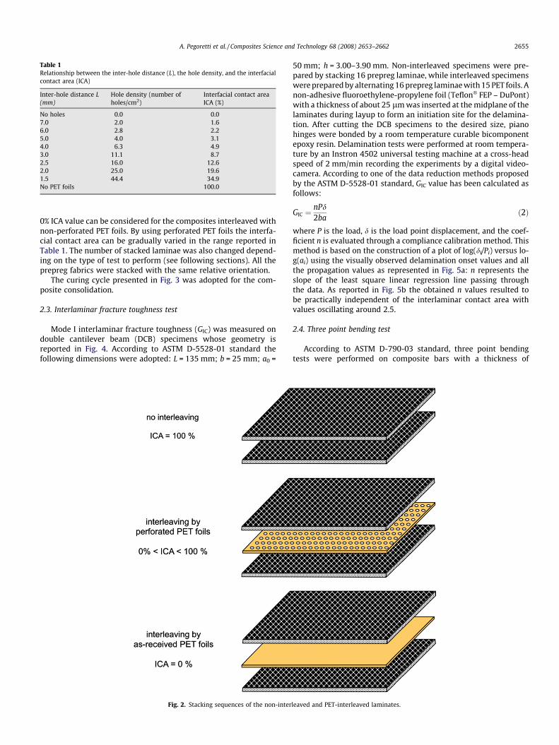
Table 1Relationship between the inter-hole distance (L), the hole density, and the interfacialcontact area (ICA)
Inter-hole distance L(mm)
Hole density (number ofholes/cm2)
Interfacial contact areaICA (%)
No holes 0.0 0.07.0 2.0 1.66.0 2.8 2.25.0 4.0 3.14.0 6.3 4.93.0 11.1 8.72.5 16.0 12.62.0 25.0 19.61.5 44.4 34.9No PET foils 100.0
A. Pegoretti et al. / Composites Science and Technology 68 (2008) 2653–2662 2655
0% ICA value can be considered for the composites interleaved withnon-perforated PET foils. By using perforated PET foils the interfa-cial contact area can be gradually varied in the range reported inTable 1. The number of stacked laminae was also changed depend-ing on the type of test to perform (see following sections). All theprepreg fabrics were stacked with the same relative orientation.
The curing cycle presented in Fig. 3 was adopted for the com-posite consolidation.
2.3. Interlaminar fracture toughness test
Mode I interlaminar fracture toughness (GIC) was measured ondouble cantilever beam (DCB) specimens whose geometry isreported in Fig. 4. According to ASTM D-5528-01 standard thefollowing dimensions were adopted: L = 135 mm; b = 25 mm; a0 =
Fig. 2. Stacking sequences of the non-inter
50 mm; h = 3.00–3.90 mm. Non-interleaved specimens were pre-pared by stacking 16 prepreg laminae, while interleaved specimenswere prepared by alternating 16 prepreg laminae with 15 PET foils. Anon-adhesive fluoroethylene-propylene foil (Teflon� FEP – DuPont)with a thickness of about 25 lm was inserted at the midplane of thelaminates during layup to form an initiation site for the delamina-tion. After cutting the DCB specimens to the desired size, pianohinges were bonded by a room temperature curable bicomponentepoxy resin. Delamination tests were performed at room tempera-ture by an Instron 4502 universal testing machine at a cross-headspeed of 2 mm/min recording the experiments by a digital video-camera. According to one of the data reduction methods proposedby the ASTM D-5528-01 standard, GIC value has been calculated asfollows:
GIC ¼nPd2ba
ð2Þ
where P is the load, d is the load point displacement, and the coef-ficient n is evaluated through a compliance calibration method. Thismethod is based on the construction of a plot of log(di/Pi) versus lo-g(ai) using the visually observed delamination onset values and allthe propagation values as represented in Fig. 5a: n represents theslope of the least square linear regression line passing throughthe data. As reported in Fig. 5b the obtained n values resulted tobe practically independent of the interlaminar contact area withvalues oscillating around 2.5.
2.4. Three point bending test
According to ASTM D-790-03 standard, three point bendingtests were performed on composite bars with a thickness of
leaved and PET-interleaved laminates.

20
40
60
80
100
120
0
1
2
3
4
5
0 20 40 60 80 100 120 140
tem
pera
ture
[°C
] pressure [MP
a]
time [min]
Fig. 3. Temperature and pressure profiles adopted for the composites curing cycle.
Fig. 4. Schematic of the DCB specimens.
-0.8
-0.7
-0.6
-0.5
-0.4
-0.3
-0.2
-0.1
1.6 1.65 1.7 1.75 1.8 1.85 1.9 1.95 2
y = -4.8517 + 2.4617x R= 0.98539
log
δ/P
[mm
/N]
log a [mm]
1.5
2
2.5
3
3.5
0 20 40 60 80 100
n
interlaminar contact area [%]
Fig. 5. (a) Typical compliance calibration plot and (b) n exponent as a function ofthe interlaminar contact area.
2656 A. Pegoretti et al. / Composites Science and Technology 68 (2008) 2653–2662
1.7 mm, a width of 12.7 mm and a length of 110 mm. The test barswere machined out of composite plates consisting of eight prepreglaminae (non-interleaved composites) or of eight prepreg laminaeinterleaved with seven PET foils. Load–deflection curves were ob-tained at room temperature by an Instron 4502 machine at across-head speed of 5 mm/min at a span length of 80 mm. At leastfive specimens were tested for each sample. According to ASTM D-790-03 standard, a bending modulus, Eb, and a bending strength,rb, were calculated by using the following formulae:
Eb ¼S3m
4bd3 ð3Þ
rb ¼3PmaxS
2bd2 ð4Þ
where S is the span length, b the width and d the thickness of thespecimen, Pmax, the maximum measured load, and m the slope ofthe tangent to the initial straight-line portion of the load–deflectioncurve.
2.5. Instrumented Charpy impact test
Instrumented Charpy impact tests were performed on test barsof rectangular cross section, 80 mm long, 10 mm wide and 1.7 mmthick machined from the same laminates where specimens forthree point bending test were obtained from. Tests were performed
by a CEAST model 6549 instrumented impact pendulum. Speci-mens were supported to the machine anvils at a span length of40 mm and broken by a single swing of the pendulum with the im-pact line midway between the supports in the flat wise direction.The striking nose of the pendulum was characterized by an in-cluded angle of 30� and a tip rounded to a radius of 2 mm. Thestriking hammer impacted the specimens at a speed of 2 m/s andwith a kinetics energy of 1.91 J. Load-time data points were ac-quired at a sampling time of 0.01 ms. At least 10 specimens weretested for each sample.
All the acquired load-time curves were elaborated by the CEASTsoftware DAS4000 Extended Win Acquisition System ver. 3.30 inorder to obtain the load–displacement and energy–displacementcurves.
Bending modulus, Eb, and bending strength, rb, under impactconditions were calculated on the basis of Eqs. (3) and (4),respectively.
3. Results and discussion
3.1. Interlaminar fracture toughness
Optical micrographs of the cross section of composites, inter-leaved with both as-received and perforated PET foils, are reportedin Fig. 6. In Fig. 6a it is very easy to identify the presence of the as-received (unperforated) PET interleaving foils separating the com-posite laminae. When perforated PET foils are used the typicalcomposite structure is depicted in Fig. 6b and c, in which the black

A. Pegoretti et al. / Composites Science and Technology 68 (2008) 2653–2662 2657
arrows indicate the borders of a hole in the PET foils. In most cases,the epoxy matrix was able to flow through the holes in the inter-leaving foils during composite preparation, as represented in Fig.6b, thus forming a resin bridge between two adjacent compositelaminae. The number of these resin bridges obviously increaseswith the number of holes per unit area, and hence the interlaminarcontact area (ICA), increases. In a few cases (upper and lower partsof Fig. 6c) the resin was not able to flow completely through theholes, and micro-voids were created in the laminate.
Fig. 6. Optical micrographs of the cross section of composites interleaved with(a) as-received, (b) and (c) perforated PET foils (ICA = 19.6%).
The load–displacement curves for DCB delamination tests per-formed on composites with various interlaminar contact areasare compared in Fig. 7. It is interesting to observe that these curvestends to reach higher load values as the interlaminar contact area(and hence the number of resin bridges per unit area) increases.According to the data reduction procedures suggested by ASTMstandard D-5528-01, an initiation GIC value can be determinedusing the load and deflection data measured at the point of devia-tion from linearity in the load–displacement curve (GIC,NL), or at thepoint at which delamination is visually observed (GIC,VIS) on theedge of the DCB specimen:
GIC;NL ¼nPNLdNL
2bað5Þ
GIC;VIS ¼nPVISdVIS
2bað6Þ
where the symbols have the same meaning as in Eq. (2) with the sub-scripts NL and VIS referring to the point of deviation from linearity inthe load–displacement curve and to the point at which delaminationis visually observed, respectively. The initiation GIC values obtainedusing Eqs. (5) and (6) are reported in Fig. 8 as a function of the inter-laminar contact area of the laminates. As expected, the interlaminartoughness values for fracture initiation increase as the interlaminarcontact area increase, due to the increasing numbers of interlaminarresin bridges. It is worth observing that, independently of the datareduction method, the initiation interlaminar fracture toughness ofthe composites interleaved with as-received PET foils (ICA = 0%) as-sumes a value of about 40 J/m2. This indicates a relatively good adhe-sion level between the PET foils and the epoxy matrix. GIC,VIS andGIC,NL values are very similar up to interlaminar contact areas ofabout 40%, while they markedly differ for the non-interleaved com-posites which display GIC,NL and GIC,VIS values of about 260 J/m2 and430 J/m2, respectively. In the continuation of this article we will referto GIC,NL values since the underlying data reduction method is morestraightforward. From the data reported in Fig. 9 it is possible to ob-serve that the interlaminar contact area also markedly affects thedelamination resistance curves. In fact, as the interlaminar contactarea decreases R curves tend to flatten and level off at progressivelylower limiting values. For low ICA values the delamination resistanceis practically independent of the crack length.
At this point, before to present the results of quasi-static andimpact tests, it is important to underline that we are conscious thatthree point bending tests carried out on unnotched specimens aremostly characterized by a sliding mode (Mode II) rather than an
0
10
20
30
40
50
60
0 5 10 15 20 25 30
load
[N]
displacement [mm]
a)
b)
c)d)
e)f)
Fig. 7. Load–displacement curves for DCB delamination tests performed on com-posites with various interlaminar contact areas: (a) ICA = 100%, (b) ICA = 34.9%,(c) ICA = 12.6%, (d) ICA = 8.7%, (e) ICA = 3.1%, (f) ICA = 0%.

0
100
200
300
400
500
0 20 40 60 80 100
GIC,NL
GIC,VIS
GIC
[J/m
2 ]
interlaminar contact area [%]
50
100
150
0 5 10 15 20 25 30 35 40
GIC
[J/m
2]
interlaminar contact area [%]
Fig. 8. Mode I interlaminar fracture toughness evaluated at first deviation fromlinearity (s, GIC,NL) and at visual onset of delamination (h, GIC,VIS), as a function ofthe interlaminar contact area.
0
200
400
600
800
0 10 20 30
ICA = 100 %ICA = 34.9 %ICA = 8.7 %ICA = 2.2 %
GIC
[J/m
2 ]
crack length increase, Δa [mm]
Fig. 9. Effect of the interlaminar contact area on the delamination resistance curve(R curve).
30
35
40
45
50
55
60
65
70
300
400
500
600
700
800
900
1000
0 50 100 150 200 250 300
bend
ing
mod
ulus
, Eb [G
Pa]
bending strength, σb [M
Pa]
bending strength, σb [M
Pa]
GIC,NL
[J/m2]
V = 5 mm/min
30
35
40
45
50
55
60
65
70
300
400
500
600
700
800
900
1000
0 50 100 150 200 250 300
bend
ing
mod
ulus
, Eb [G
Pa]
GIC,NL
[J/m2]
V = 2 m/s
Fig. 10. Effect of the interlaminar fracture toughness (GIC,NL) on the bending mo-dulus (d) and strength (j) measured under (a) quasi-static (5 mm/min) and (b)impact (2 m/s) conditions.
2658 A. Pegoretti et al. / Composites Science and Technology 68 (2008) 2653–2662
opening mode (Mode I). Unfortunately, there is no European norASTM mode II standard at present, but the JIS group has a modeII test procedure based on the ENF specimen and an option to allowstabilising the test [41]. At the same time, it is worthwhile to notethat most of the experimental data available in the scientific liter-ature indicate that a monotonic relationship exists between Mode Iand Mode II interlaminar fracture toughness. In other words, withonly few exceptions [42,43], when Mode I interlaminar fracturetoughness increases, Mode II interlaminar fracture toughness gen-erally does the same [20,21,44–49]. An estimation of the interlam-inar shear strength (ISS) by the short-beam shear test (ASTM D2344) was also considered, but the small specimens dimensions re-quired for this testing procedure posed a serious limitation on theusefulness of this test for the materials under investigation. In fact,according to ASTM D 2344 standard, specimen with span-to-thick-ness and a width-to-thickness ratios of 4 and 2, respectively are re-quired. This would have lead to samples with as low as 1–2 resinbridges per lamina, in the case of composites interleaved with foilshaving the lowest holes densities. As a consequence, the specimenswould have not been representative of the situation at a macroscale, like that encountered in quasi-static and impact three pointbending tests. On the basis of the above considerations, GIC value
has been preferred as a parameter representative of the interlam-inar fracture toughness.
3.2. Quasi-static mechanical tests
The mechanical behaviour under quasi-static loading conditionshas been investigated by three point bending tests whose resultsare summarized in Fig. 10a. In this figure, the bending modulus,Eb, and the bending strength, rb, are plotted as a function of theinterlaminar fracture toughness for crack initiation. Interestinglyenough, the bending modulus is practically independent of theinterlaminar fracture toughness, while the bending strength dis-play a tendency to increase as GIC,NL increases. The observed depen-dence of composite modulus and strength on the interlaminarfracture toughness closely resembles their dependence on the fi-bre–matrix adhesion. In fact, the observed behaviour is consistentwith the existing literature on the effects of fibre–matrix adhesionon the quasi-static tensile and flexural mechanical properties ofepoxy/graphite unidirectional composites. As reported by Madhu-kar and Drzal [50] and by Deng and Le [29] the fibre surface mod-ification do not have much effect on the tensile and flexural moduliand on the fibre dominated properties. However, the strengths andthe maximum strains, that are governed by the matrix and inter-face properties, are highly sensitive to the fibre surface modifica-tion. On the basis of our findings, similar considerations can be

A. Pegoretti et al. / Composites Science and Technology 68 (2008) 2653–2662 2659
put forward on the effect of interlaminar fracture toughness on theflexural properties of carbon/epoxy fabric laminates.
3.3. Impact resistance
The bending modulus, Eb, and the bending strength, rb, havebeen also evaluated under impact conditions by means of instru-mented Charpy tests. The obtained values, plotted as a functionof the interlaminar fracture toughness for crack initiation, are re-ported in Fig. 10b. It is interesting to note that, under impact con-ditions, both bending modulus and strength display a trend similarto that observed under quasi-static conditions. As expected, due tothe viscoelastic behaviour of the PET interleaving foils and of theepoxy matrix, the stiffness and strength values of interleaved com-posites under impact conditions are higher than the correspondingdata measured at a lower strain rate.
Fig. 11 documents the conditions of some of the investigatedlaminates after the Charpy impact test. It clearly emerges thatthe fracture behaviour under low speed impact conditions is pro-foundly affected by the interlaminar fracture toughness of thetested composites. For non-interleaved composites, that displaythe highest GIC,NL values, the broken specimens show a typicallybrittle aspect, with relatively sharp fracture surfaces and no (orvery little) delamination damages (see Fig. 11a). When the inter-laminar fracture toughness decreases, the failure process of the im-pacted specimens is characterized by progressively increasingdelamination damage, and more extended fracture surfaces. For
Fig. 11. Pictures of specimens after the Charpy impact test: (a) GIC,NL = 262 J/m2 (ICA(d) GIC,NL = 62 J/m2 (ICA = 4.9%).
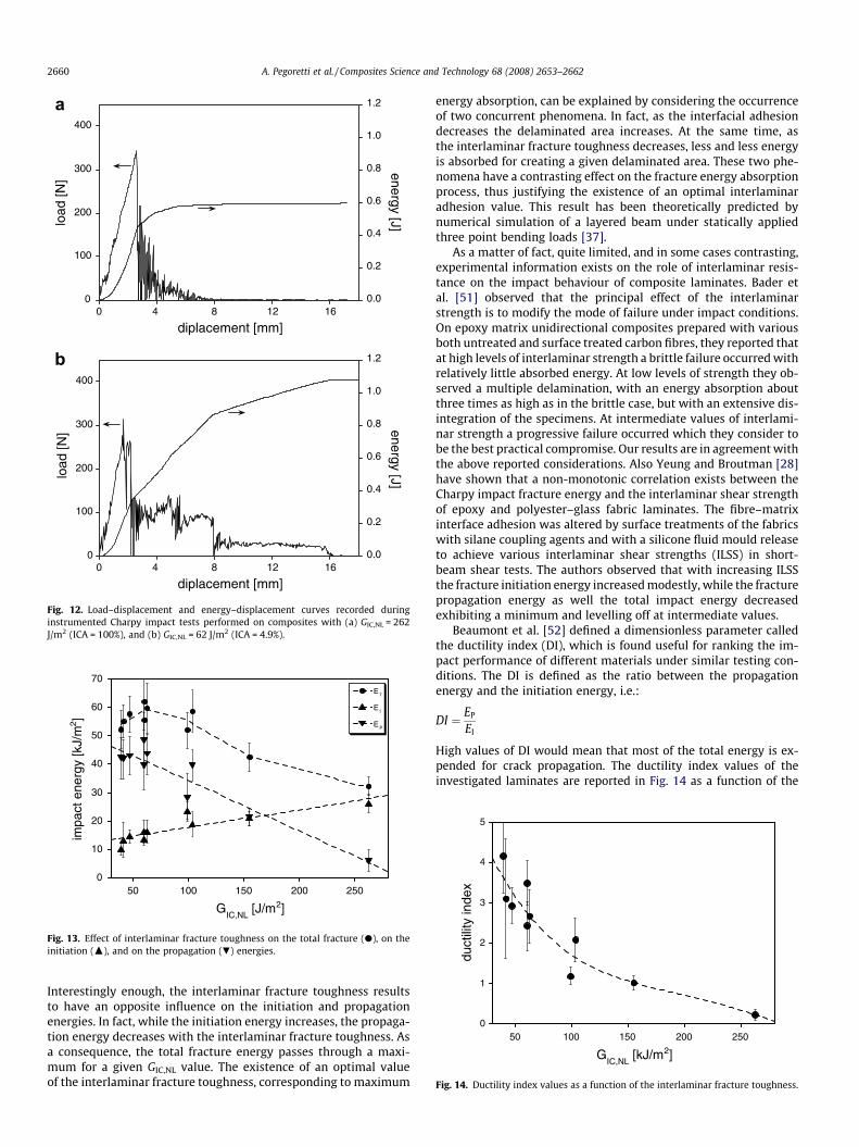
the lowest interlaminar fracture toughness values a certain disin-tegration of the tested specimens is also observed. Depending onthe different fracture mechanisms, the load–displacement and en-ergy–displacement curves recorded during the Charpy instru-mented tests also markedly change with the interlaminarfracture toughness of the investigated laminates. By way of exam-ples, the typical impact curves of two different laminates are re-ported in Fig. 12. It is evident that the brittle failure mode ofnon-interleaved composites (Fig. 12a) results in a load–displace-ment curve characterized by a sudden load drop with practicallyno energy consumed for the cracks propagation process. On theother hand, the load–displacement curve of interleaved compositesdisplays a different trend, being a large amount of energy absorbedfor damage delamination processes (Fig. 12b). For the case re-ported in Fig. 12b, which refers to an interleaved composite witha low (4.9%) ICA value, the total impact fracture energy exceedsby a factor of about 1.8 the energy absorbed by non-interleavedcomposites.
For each specimen, the total fracture energy (ET) could be eval-uated by measuring the total area under the curve and normalisingit to the specimen cross sectional area. ET is the sum of a crack ini-tiation energy (EI) and a crack propagation energy (EP). The initia-tion energy is the energy measured up to the first load drop, whilethe propagation energy is the energy required from this point tobreak the specimen. Total fracture, initiation, and propagation im-pact energies are summarised in Fig. 13 as a function of the inter-laminar fracture toughness of the investigated laminates.
= 100%), (b) GIC,NL = 155 J/m2 (ICA = 34.9%), (c) GIC,NL = 103 J/m2 (ICA = 12.6%), and
0
100
200
300
400
0.0
0.2
0.4
0.6
0.8
1.0
1.2
0 4 8 12 16
load
[N]
energy [J]
diplacement [mm]
0 4 8 12 16
diplacement [mm]
0
100
200
300
400
0.0
0.2
0.4
0.6
0.8
1.0
1.2
load
[N] energy [J]
Fig. 12. Load–displacement and energy–displacement curves recorded duringinstrumented Charpy impact tests performed on composites with (a) GIC,NL = 262J/m2 (ICA = 100%), and (b) GIC,NL = 62 J/m2 (ICA = 4.9%).
0
10
20
30
40
50
60
70
50 100 150 200 250
E
E
E
impa
ct e
nerg
y [k
J/m
2 ]
GIC,NL
[J/m2]
Fig. 13. Effect of interlaminar fracture toughness on the total fracture (d), on theinitiation (N), and on the propagation (.) energies.
0
1
2
3
4
5
50 100 150 200 250
duct
ility
inde
x
GIC,NL
[kJ/m2]
Fig. 14. Ductility index values as a function of the interlaminar fracture toughness.
2660 A. Pegoretti et al. / Composites Science and Technology 68 (2008) 2653–2662
Interestingly enough, the interlaminar fracture toughness resultsto have an opposite influence on the initiation and propagationenergies. In fact, while the initiation energy increases, the propaga-tion energy decreases with the interlaminar fracture toughness. Asa consequence, the total fracture energy passes through a maxi-mum for a given GIC,NL value. The existence of an optimal valueof the interlaminar fracture toughness, corresponding to maximum
energy absorption, can be explained by considering the occurrenceof two concurrent phenomena. In fact, as the interfacial adhesiondecreases the delaminated area increases. At the same time, asthe interlaminar fracture toughness decreases, less and less energyis absorbed for creating a given delaminated area. These two phe-nomena have a contrasting effect on the fracture energy absorptionprocess, thus justifying the existence of an optimal interlaminaradhesion value. This result has been theoretically predicted bynumerical simulation of a layered beam under statically appliedthree point bending loads [37].
As a matter of fact, quite limited, and in some cases contrasting,experimental information exists on the role of interlaminar resis-tance on the impact behaviour of composite laminates. Bader etal. [51] observed that the principal effect of the interlaminarstrength is to modify the mode of failure under impact conditions.On epoxy matrix unidirectional composites prepared with variousboth untreated and surface treated carbon fibres, they reported thatat high levels of interlaminar strength a brittle failure occurred withrelatively little absorbed energy. At low levels of strength they ob-served a multiple delamination, with an energy absorption aboutthree times as high as in the brittle case, but with an extensive dis-integration of the specimens. At intermediate values of interlami-nar strength a progressive failure occurred which they consider tobe the best practical compromise. Our results are in agreement withthe above reported considerations. Also Yeung and Broutman [28]have shown that a non-monotonic correlation exists between theCharpy impact fracture energy and the interlaminar shear strengthof epoxy and polyester–glass fabric laminates. The fibre–matrixinterface adhesion was altered by surface treatments of the fabricswith silane coupling agents and with a silicone fluid mould releaseto achieve various interlaminar shear strengths (ILSS) in short-beam shear tests. The authors observed that with increasing ILSSthe fracture initiation energy increased modestly, while the fracturepropagation energy as well the total impact energy decreasedexhibiting a minimum and levelling off at intermediate values.
Beaumont et al. [52] defined a dimensionless parameter calledthe ductility index (DI), which is found useful for ranking the im-pact performance of different materials under similar testing con-ditions. The DI is defined as the ratio between the propagationenergy and the initiation energy, i.e.:
DI ¼ EP
EI
High values of DI would mean that most of the total energy is ex-pended for crack propagation. The ductility index values of theinvestigated laminates are reported in Fig. 14 as a function of the

A. Pegoretti et al. / Composites Science and Technology 68 (2008) 2653–2662 2661
interlaminar fracture toughness. Even if the data are affected bysome scattering, they clearly show that the ductility index markedlyincreases as the interlaminar fracture toughness decreases. In par-ticular, for the lowest explored value of the interlaminar fracturetoughness the fracture propagation energy is almost four timeshigher that the fracture initiation component.
4. Conclusions
The Mode I interlaminar fracture toughness of carbon–epoxylaminates has been selectively varied, in the range from 40 up to260 J/m2, by interleaving with as-received and perforated PET foils.Its effect on quasi-static and impact mechanical response has beeninvestigated by three point bending tests.
The following conclusions can be drawn:
(i) The bending modulus determined both under quasi-staticand impact conditions is practically independent of the inter-laminar fracture toughness.
(ii) The bending strength determined both under quasi-static andimpact conditions markedly increase as the interlaminar frac-ture toughness increases.
(iii) The interlaminar fracture toughness has an opposite effect onthe initiation and propagation energies under impact condi-tions. In fact, while the initiation energy increases, the prop-agation energy decreases with the interlaminar fracturetoughness. As a consequence, the total fracture energy passesthrough a maximum for a given interlaminar fracture tough-ness value, for which the total impact energy increases is 1.8times higher than the value observed for non-interleavedcomposites. The ductility index steadily increases from 0.2up to 4.2 as the interlaminar fracture toughness decreases.
Acknowledgments
The authors are grateful to Dr Martina Corasaniti of SEAL S.p.A.Legnano (MI), Italy for the selection and supply of the carbon–epoxy prepregs.
References
[1] Mallick PK. Fiber-reinforced composites: materials, manufacturing, anddesign. New York: Marcel Dekker, Inc.; 1993.
[2] Richardson MOW, Wisheart MJ. Review of low-velocity impact properties ofcomposite materials. Compos Part A 1996;27(12):1123–31.
[3] Hancox NL. An overview of the impact behavior of fibre-reinforced composites.In: Reid SR, Zhou G, editors. Impact behaviour of fibre-reinforced compositematerials and structures. Cambridge, UK: Woodhead Publishing Ltd.; 2000. p.1–32.
[4] Johnson AF, Holzapfel M. Influence of delamination on impact damage incomposite structures. Compos Sci Technol 2006;66:807–15.
[5] Larsson F. Damage tolerance of a stitched carbon/epoxy laminate. Compos PartA 1997;28(11):923–34.
[6] Kim JK, Mackay DB, Mai Y-W. Drop-weight impact damage tolerance of CFRPwith rubber modified epoxy matrix. Composites 1993;24(6):485–94.
[7] Jang K, Cho W-J, Ha C-S. Influence of processing method on the fracture toughnessof thermoplastic-modified, carbon-fiber-reinforced epoxy composites. ComposSci Technol 1999;59(7):995–1001.
[8] Sjogren BA, Berglund LA. Toughening mechanisms in rubber-modifiedglass fiber/unsaturated polyester composites. Polym Compos 1999;20(5):705–12.
[9] Verrey J, Winkler Y, Michaud V, Manson J-AE. Interlaminar fracture toughnessimprovement in composites with hyperbranched polymer modified resin.Compos Sci Technol 2005;65:1527–36.
[10] Jain LK, Mai Y-W. In the effect of stitching on mode-I delamination toughnessof laminated composites. Compos Sci Technol 1994;51(3):331–45.
[11] Jain LK, Mai Y-W. Determination of Mode II delamination toughness of stitchedlaminated composites. Compos Sci Technol 1995;55(3):241–53.
[12] Dransfield KA, Jain LK, Mai Y-W. On the effects of stitching in CFRPs—I. Mode Idelamination toughness. Compos Sci Technol 1998;59(6):815–27.
[13] Jain LK, Dransfield KA, Mai Y-W. On the effects of stitching in CFRPs—II. Mode IIdelamination toughness. Compos Sci Technol 1998;59(6):829–37.
[14] Watt A, Goodwin AA, Mouritz AP. Thermal degradation of the mode Iinterlaminar fracture properties of stitched glass fibre vinyl estercomposites. J Mater Sci 1998;33(10):2629–38.
[15] Yan WY, Liu HY, Mai Y-W. Mode II delamination toughness of z-pinnedlaminates. Compos Sci Technol 2004;64(13–14):1937–45.
[16] Cartie DDR, Troulis M, Partridge IK. Delamination of Z-pinned carbon fibrereinforced laminates. Compos Sci Technol 2006;66(6):855–61.
[17] Davidson BD, Hu H. Effect of interlayer modulus on fracture mode ratio forinterleaved composite laminates. Eng Fract Mech 1995;52(2):243–53.
[18] Hillermeier RW, Seferis JC. Interlayer toughening of resin transfer moldingcomposites. Compos Part A 2001;32:721–9.
[19] Jiang W, Y TFF, Tjong SC, Li RKY, Kim JK, Mai Y-W. Loading rate dependence ofMode II fracture behavior in interleaved carbon fibre/epoxy compositelaminates. Appl Compos Mater 2001;8:361–9.
[20] Lee S-H, Noguchi H, Kim Y-B, Cheong S-K. Effect of interleaved non-wovencarbon tissue on interlaminar fracture toughness of laminated composites:Part I – Mode II. J Compos Mater 2002;36(18):2153–67.
[21] Lee S-H, Noguchi H, Kim Y-B, Cheong S-K. Effect of interleaved non-wovencarbon tissue on interlaminar fracture toughness of laminated composites:Part II – Mode I. J Compos Mater 2002;36(18):2169–81.
[22] Matsuda S, Hojo M, Ochiai S, Murakami A, Akimoto H, Ando M. Effect ofionomer thickness on mode I interlaminar fracture toughness for ionomertoughened CFRP. Compos Part A 1999;30:1311–9.
[23] Yun NG, Won YG, Kim SC. Toughening of carbon fiber/epoxy composite byinserting polysulfone film to form morphology spectrum. Polymer2004;45:6953–8.
[24] Gao F, Jiao GQ, Lu ZX, Ning RC. Mode II delamination and damage resistance ofcarbon/epoxy composite laminates interleaved with thermoplastic particles. JCompos Mater 2007;41(1):111–23.
[25] Walker L, Sohn MS, Hu XZ. Improving impact resistance of carbon-fibrecomposites through interlaminar reinforcement. Compos Part A – Appl SciManufact 2002;33(6):893–902.
[26] Kim JK, Mai Y-W. Engineered interfaces in fibre-reinforced compos-ites. Oxford: Elsevier Science Publishers; 1998.
[27] Wang TWH, Blum FD. Interfacial mobility and its effect on interlaminarfracture toughness in glass-fibre-reinforced epoxy laminates. J Mater Sci1996;31(19):5231–8.
[28] Yeung P, Broutman LJ. The effect of glass–resin interface strength on theimpact strength of fiber reinforced plastics. Polym Eng Sci 1978;18(2):62–72.
[29] Deng SQ, Ye L. Influence of fiber–matrix adhesion on mechanical properties ofgraphite/epoxy composites: I. Tensile, flexure, and fatigue properties. J ReinfPlast Compos 1999;18(11):1021–40.
[30] Madhukar MS, Drzal LT. Fiber–matrix adhesion and its effect on compositemechanical properties: IV. Mode I and Mode II fracture toughness of graphite/epoxy composites. J Compos Mater 1992;26(7):936–68.
[31] Goan JC, Martin TW, Prescott R. The influence of interfacial bonding on theproperties of carbon fiber composites. In: 28th Annual Technical ConferenceReinforced Plastic Composites Institute; 1973: SPI.
[32] Hong S, Liu D. On the relationship between impact energy and delaminationarea. Exp Mech 1989;29(2):115–20.
[33] Favre JP. Improving the fracture energy of carbon fiber reinforced plastics bydelamination promoters. J Mater Sci 1977;12:43–50.
[34] Mai YW, Cotterell B, Lord R. On fiber composites with intermittentinterlaminar bonding. In: ICCM-IV, progress in science and engineering ofcomposites. Tokyo: North Holland Pub, Amsterdam; 1982.
[35] Jea LC, Felbeck DK. Increased fracture toughness of graphite–epoxy compositesthrough intermittent interlaminar bonding. J Compos Mater 1980;14:245–59.
[36] Jang BZ, Lieu YK, Chung WC, Hwang LR. Controlled energy dissipation infibrous composites, I. Controlled delamination. Polym Compos 1987;8:94–102.
[37] Lear MH, Sankar BV. Optimizing energy absorption in multi-layered materialsthrough controlled delamination. J Mater Sci 1999;34(17):4181–91.
[38] Schoeppner GA, Abrate S. Delamination threshold loads for low velocityimpact on composite laminates. Compos Part A – Appl Sci Manufact2000;31(9):903–15.
[39] Fuoss E, Straznicky PV, Poon C. Effects of stacking sequence on the impactresistance in composite laminates – Part 1: parametric study. Compos Struct1998;41(1):67–77.
[40] Pegoretti A, Guardini A, Migliaresi C, Ricco T. Recovery of post-yieldingdeformations in semi-crystalline poly(ethylene-terephthalate). Polymer2000;41(5):1857–64.
[41] Davies P, Blackman BRK, Brunner AJ. Mode II delamination. In: Moore DR,Pavan A, Williams JG, editors. Fracture mechanics testing methods forpolymers, adhesives and composites. Amsterdam: Elsevier; 2001. p.307–33.
[42] Hojo M, Ando T, Tanaka M, Adachi T, Ochiai S, Endo Y. Modes I andII interlaminar fracture toughness and fatigue delamination of CF/epoxy laminates with self-same epoxy interleaf. Int J Fatigue2006;28:1154–65.
[43] Naik NK, Reddy KS, Meduri S, Raju NB, Prasad PD, Azad SNM, et al. Interlaminarfracture characterization for plain weave fabric composites. J Mater Sci2002;37:2983–7.
[44] Alvarez V, Bernal CR, Frontini PM, Vazquez A. The influence ofmatrix chemicalstructure on the Mode I and II interlaminar fracture toughness of glass-fiber/epoxy composites. Polym Compos 2003;24(1):140–8.

2662 A. Pegoretti et al. / Composites Science and Technology 68 (2008) 2653–2662
[45] Chen SF, Jang BZ. Fracture behavior of interleaved fiber resin composites.Compos Sci Technol 1991;41(1):77–97.
[46] Jordan W. Changing the toughness of graphite fiber/resin basedcomposites by changing their internal structure. Compos Part B2000;31:245–52.
[47] Mujika F, De Benito A, Fernadez B, Vazquez A, Llano-Ponte R, Mondragon I.Mechanical properties ofcarbon woven reinforced epoxy matrix composites. Astudy on the influence of matrix modification with polysulfone. PolymCompos 2002;23(3):372–82.
[48] Park SJ, Seo MK, Lee JR. Roles of interfaces between carbon fibers and epoxymatrix on interlaminar fracture toughness of composites. Compos Interfaces2006;13(2-3):249–67.
[49] Stevanovica D, Kalyanasundaramb S, Lowe A, Jarc P-YB. Mode I andmode II delamination properties of glass/vinyl-ester compositetoughened by particulate modified interlayers. Compos Sci Technol2003;63:1949–64.
[50] Madhukar MS, Drzal LT. Fiber–matrix adhesion and its effect on compositemechanical properties: II. Longitudinal (0�) and transverse (90�) tensile andflexure behavior of graphite/epoxy composites.J Compos Mater 1991;25: 958–91.
[51] Bader MG, Bailey JE, Bell I. The effect of fibre–matrix interface strength on theimpact and fracture properties of carbon-fibre-reinforced epoxy resincomposites. J Phys D: Appl Phys 1973;6:572–86.
[52] Beaumont PWR, Reiwald PG, Zweben C. Methods for improving the impactresistance of composite materials. ASTM Special Tech Public 1974;568: 134–58.


![arXiv:1610.00307v2 [cs.CV] 25 Apr 2017 · Moin Nabi2 moin.nabi@unitn.it Hossein Mousavi1 hossein.mousavi@iit.it Enver Sangineto 2 enver.sangineto@unitn.it Nicu Sebe niculae.sebe@unitn.it](https://img.pdfslide.net/doc/110x75/5fa14910cca3601efe330d61/arxiv161000307v2-cscv-25-apr-2017-moin-nabi2-moinnabiunitnit-hossein-mousavi1.jpg)