Embed Size (px)
Citation preview
1
Comprehensive aircraft configuration designer for integrated product and process
development
Abdulaziz Azamatov, Jae-Woo Lee∗ and Yung-Hwan Byun
Department of Aerospace Information Engineering, Konkuk University, 1 Hwayang-dong, Gwangjin-gu, 143-701 Seoul, Korea
Abstract This paper describes an efficient aircraft geometry design tool which is necessary for design and analysis applications through Integrated Product and Process Development (IPPD). The design process decomposes aircraft geometry into several components to represent it precisely and realistically with a reduced number of shape control parameters. For this purpose, several configuration representation algorithms are thoroughly investigated and discussed. The proposed configuration generation algorithm employs the super ellipse equation with polynomial distribution functions, Class function/Shape function Transformation (CST) and can represent and manipulate complex shapes accurately with a small number of control parameters. A model of aircraft geometry, represented in this approach, can be applied to any stage of aircraft design and development with realistic and accurate configuration data. A solution for connecting and storing the represented shapes in a Product Data Management system is also developed and demonstrated. The proposed configuration design tool could be especially efficient when automation, flexibility and rapid changes of geometry are required in a short time and with low computational resources.
Keywords: Aircraft design; Wireframe; Parameterization; Aerodynamic surface representation; IPPD Notations
API – Application Programming Interface BOM – Bill of Materials CAD – Computer Aided Design CAE – Computer Aided Engineering CAGD – Computer Aided Geometry Design CFD – Computational Fluid Dynamics CST – Class function/Shape function Transformation DB – Database DMU – Digital Mock-Up EDF – Elliptical and Distribution Functions FEA – Finite Element Analysis GUI – Graphical User Interface IPPD – Integrated Product and Process Development MDO – Multidisciplinary Design Optimization PDM – Product Data Management UAV – Unmanned Aerial Vehicle
∗ Corresponding author. Tel.: 82.2.450.4224; Fax: 82.2.444.6670; E-mail addresses: [email protected] (A.Azamatov), [email protected] (J.-W. Lee), [email protected] (Y.-H. Byun)

2
1. Introduction
Geometry definition plays a key role in aircraft design, development and optimization. For efficient geometry generation, especially during the early stage of design, a step before the application of automated geometry generation is needed, i.e. a toolbox that will produce generic and parameterized aerodynamic surfaces, which takes into account special requirements and constraints. Among well-known general CAD packages, very few are specialized to aircraft design. General CAD systems offer solutions for providing data for general engineering systems and thus cannot entirely fulfil all configuration requirements of aircraft development throughout all design phases.
Several authors, including Trapp, Sobieczky [1, 2], Kulfan [3–5], Samareh [6] and Athanasopoulos [7], have studied and developed representation techniques and methods to overcome the aforementioned issues with aircraft shape representation. Among configuration design tools for aircraft, Generic Parameterized Aircraft Surface (Ge.P.A.S.) [8], RAGE [9] and RDS-Professional [10] are specialized to fixed wing aircraft design, and HESCAD [11] is specialized to the pre-conceptual design stage of rotorcraft. There are many parametric geometry creation and manipulation tools with GUIs [12–16]. These tools can provide considerable cost savings in the product design process through reduction of design time. For example, Vehicle Sketch Pad (VSP) [17] parametric geometry modelling tool developed by NASA is getting popularity in conceptual design of aircraft. Recently, in most CAD systems, special tools for customization or Application Programming Interface (API) connection are being improved, such as CAA, CATIA VBA, UGS NX Open API, etc. It is clear that the implementation of these new features in representation algorithms will give better functionality in terms of integration ability and suitability for MDO and IPPD.
In recent years, engineering systems, including automobile, ship and aircraft are being considered concurrently with different disciplines and objectives applied to the analysis of effects at the early stage of design. This is known as Integrated Product and Process Development (IPPD). However, analysis modules and disciplines are still not connected smoothly to the geometry module. Price et al. [18, 19] have investigated current developments and status of the integrated design approach.
Kulfan [3, 5] defines the desirable features of promising aerodynamic geometric representation techniques as: (a) mathematical efficiency (i.e. smoothness along axis, accuracy, numerical stability and robustness); (b) consistency and intuitiveness; (c) representation ability with a few variables and easy control capability (i.e. flexibility). However, to meet all these requirements in geometry representation is not an easy task. The main issue is how to define an acceptable (smooth, continuous, flexible, intuitive, robust, low-cost, etc.) geometry representation method while satisfying all these requirements.

3
This paper presents an automated configuration design method and tool for the more realistic representation of various aerospace vehicle geometries using fewer control parameters. The design tool builds an aircraft geometry using typical and common components and intended for using them in conceptual and preliminary design phases.
The proposed design and representation tool is based on an effective use of a super elliptic formulation with exponential and polynomial distribution functions in an example of configuration design. It is demonstrated that with this design method, designers can represent the geometry more realistically, quickly and efficiently, then can store the geometry data in a Product Database Management (PDM) system, and manipulate complex shapes with a small number of control parameters. An aircraft geometry model in an associative environment, which is represented more realistically and precisely, is applicable to different stages of the design and development lifecycle. This proposed tool could be especially efficient when automation, flexibility, rapid changes and shorter development time of geometry are required with small computational resources.
The remaining sections in this paper are organized as follows. In Section 2, the main flow and algorithm of Parameter-based Comprehensive Aircraft Designer (PCAD) which combines GUI, aircraft scheme selection, surface representation using elliptical and distribution functions (EDF) and DB tools are introduced. Section 3 introduces an associative-relational design example which is implemented using CAD software and the PDM process for aircraft design in an IPPD environment. Section 4 presents practical applications of CAD customization – a Geometry Representation System (GRS) for aircraft design and optimization. Finally, a conclusion is given in section 5.
2. Parameter-based Comprehensive Aircraft Designer (PCAD)
Compared to conventional design, parametric-associative design requires greater involvement of CAE models in the early stages of the project such as the feasibility phase and the concept
Figure 1 Design expenditures in an aircraft design project [12]
Conventional Design
Time
Feasibility Phase
Parametric Associative
Design
Design Expenditures
DesignPhase
Production Phase
Concept Phase

4
phase. This will lower the overall design costs and development risks. It will also result in a more balanced cost profile during the aircraft design process [20].
An industry-oriented approach of associative design with implementation of structural analysis was introduced in Ledermann’s works [12, 13]. A complex CAD design like a complete aircraft cannot be designed as one part. A huge amount of data, components and parts have to be organized in an intelligent way. Basically these designs can be split into parts and assemblies where assemblies are built up of several parts. An associative model allows different geometric objects to be interrelated [12].
PCAD for the IPPD presented in this paper is developed by meeting requirements such as visualizing the object during the design, making necessary decisions in step-by-step fashion and planning. In addition, the CAD-based design implemented in this way allows a surface model to be used in other analysis modules, such as “Aerodynamics”, “Structural”, “CFD”, etc. The relational-associative design concept offers the possibility of using an external surface model for the design of internal components. Representation of the model with a reduced number of control parameters gives convenient performance in optimization problems. The realistic behaviour of the surface allows the model to be used to control the manufacturing process. A CAD system Digital mock-up (DMU) tool can predict clashes, gaps, various errors and ambiguous units in the assembling process. A PDM system easily handles the manipulation and automation of the whole process and manages safely all output information. The open architecture used makes the package available for connection to other applications and solutions to this system.
2.1. PCAD architecture
The PCAD conceptual architecture is introduced in Fig 2. This tool consists of a GUI
(Graphical User Interface), an aircraft “configuration scheme selection” decision-making tool, “surface coordinate points generator” (“control points grid”), customized CAD software adapted to the needs of designers and a commercial PDM tool.

5
2.2. Configuration representation algorithm
There are several crucial issues affecting the representation aircraft geometry in terms of purpose and fidelity during design stages. Basically, main components and units of an aircraft can be considered as free-form surfaces.
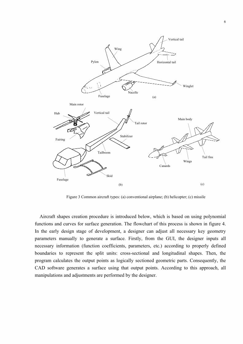
Main components of the types of aircraft that are most commonly exploited are shown in Fig.3: fixed wing airplane, helicopter and missile.
In terms of the main components, the geometry and types of most common aircraft have many similarities such as fuselages, stabilizers, wings, etc. The methods of representing such parts can also be considered to be similar. According to references [3-5, 8] aircraft components are divided into two main types: wing type geometries and fuselages or fusiform type shapes.
Figure 2 PCAD architecture
Configuration Scheme Selection
•Conventional •Compound •Utility, Military Transport •Attack, etc.
Main GUI
Fuselage
Rotor
Wing Empennage
Engine
Weapons
Fuselage
Rotor
Fairing Bump
Assembled Configuration
Product Data Management (ENOVIA Smarteam)
Vertical Tail
Horizontal Tail
Spar
Web
Cap
Inner Level Components
Skin
Filament
…
…
…
Main Parts
Engine
IGES, CGR
File formats Surface Coordinate
Points Generator
(MS Excel)
(CATIA v.5)
(MS Visual Studio)
6
Aircraft shapes creation procedure is introduced below, which is based on using polynomial
functions and curves for surface generation. The flowchart of this process is shown in figure 4. In the early design stage of development, a designer can adjust all necessary key geometry parameters manually to generate a surface. Firstly, from the GUI, the designer inputs all necessary information (function coefficients, parameters, etc.) according to properly defined boundaries to represent the split units: cross-sectional and longitudinal shapes. Then, the program calculates the output points as logically sectioned geometric parts. Consequently, the CAD software generates a surface using that output points. According to this approach, all manipulations and adjustments are performed by the designer.
Figure 3 Common aircraft types: (a) conventional airplane; (b) helicopter; (c) missile
(c)
Main body
Canards Wings
Tail fins
(b)
Main rotor Vertical tail Hub
Fairing
Fuselage
Stabilizer
Tailboom
Skid
Tail rotor
Wing
Fuselage
Vertical tail
Horizontal tail
Winglet
Pylon
Nacelle (a)

7
In the preliminary stage of design, various analysis tools are used and the representation
geometry must coincide with the initial object. Extra precision gives better results in terms of validity and robustness. Hence it reduces the preliminary design time and cost. Fig. 4 shows the fitting process for the existing shape from discrete data points to obtain the function coefficients. The obtained coefficients are used in shape generation with many points using approximation functions. The entire geometry is formed by cross-sectional and longitudinal shapes. The surface generated by CAD is stored in a PDM database. A more detailed explanation on how to generate curves, surfaces and the PDM data structure is given in the following sections.
2.2.1. CST The CST method is based on analytical expressions to represent and modify the various
shapes [3-5]. The components of this function are the “shape function” and “class function”. The shape function provides direct control over the key parameters of the geometry. The class function modifies the geometry according to class types, such as airfoil type shape, ellipse, cone type shape, etc. The curve ordinates are defined in CST by the following equation:
Figure 4 Flow-chart of surface generation process
Start
Shape breakdown
Cross sectional shapes
Longitudinal (spanwise) shapes
Function selection
Fitting
Inputs from existing shape
Coefficients
Surface generation
Cross sectional shapes representation
Longitudinal (spanwise) shapes representation
Obtain points using approximated functions
Inputs from designer’s decision
End

8
)/()/()/( 12 cxScxCcxy N
N ⋅= (1)
where 2121 )1()()( NNN
N cxcxcxC −= : class function,
[ ]∑=
⋅=n
i
ii cxAcxS
0
)/()/( : shape function,
Ai: shape function coefficients N1, N2: exponents x: non-dimensional values from 0 to 1. c: chord length To formulate the CST method, Bernstein polynomials are used as the shape function:
iniii xxKxS −−= )1()( (2)
where )!(!
!ini
nin
K−
=⎟⎟⎠
⎞⎜⎜⎝
⎛≡ : binomial coefficients
n : order of Bernstein polynomial i : numbers 0 to n
The efficiency of the airfoil representation by CST is compared with NURBS and shown in Fig. 5-a. In this example, for the NURBS generation, new points are used in a 4th order Cox de Boor algorithm and 65 points are generated for representation of each (upper and lower) curve [21]. In this case, the control variables are the ordinates of the control points (5 variables for the upper curve and 5 for the lower curve ordinates). The CST method with 4 control variables has a better fit to the existing airfoil than NURBS, which uses 10 control variables for fitting.
Fig. 5-b shows the absolute errors in airfoil generation with CST and NURBS. It is required at least 10 control points to generate the airfoil using NURBS. Generation by NURBS of the aft part of airfoil has larger errors.
Figure 5 Transonic RAE 2822 airfoil representation: (a) CST and NURBS; (b) absolute error comparison
‐0.08
‐0.06
‐0.04
‐0.02
0
0.02
0.04
0.06
0.08
0 0.2 0.4 0.6 0.8 1
NURBS C urve
C S T
C ontrol Points‐0.005
0
0.005
0.01
0.015
0.02
0.025
0 0.2 0.4 0.6 0.8 1
NURBS uppercurveNURBS lowercurveC S T upper curve
C S T lower curve
(a) (b)

9
Fig 6 shows a representation of a helicopter rotor blade with three different airfoils (cross-
sections), chord lengths, twisting, leading edge (LE) angle, and L1, L2, L3 offsets (Fig. 6)
2.2.2. Super ellipse equation The general Cartesian notation of the form comes from the French mathematician Gabriel
Lamé who generalized the equation of the ellipse:
1=+mn byax , (n,m > 0) (3)
The solution of function y becomes (Fig. 7-a):
( )mnaxby1
1−⋅= ,(n,m > 0) (4)
(a)
Figure 7 Super ellipse functions: (a) Non-dimensional functions (b) Dimensional scaled and positioned functions
0
0.2
0.4
0.6
0.8
1
0 0.2 0.4 0.6 0.8 1x
y
m=0.2 n=2 m=1.9
n=2 m=0.5 n=2
m=2.5n=3
m=7 n=4
(b)
-1.3
-1.1
-0.9
-0.7
-0.5
-0.3
-0.1
0.1
0.3
0.5
0.7
0.9
1.1
1.3
0 0.25 0.5 0.75 1 1.25
z
y
m=0.2 n=2
m=1.9 n=2
m=2.5 n=3
m=7 n=4
m=0.5 n=2
Figure 6 Rotorcraft rotor blade surface representation using CST
twist 3
twist 1
twist 2
L3
Rotation center
Angle by LE
L2
Chord length 3
Chord length 2
L1
Chord length 1

10
2.2.3. Aircraft geometry representation using elliptic and distribution functions (EDF) To capture the whole design space and to easily control the function in it, we will use Eq. (4)
in non-dimensional form, thus the a and b values should always be equal to 1. The value x should be in the interval [0, 1]. For convenience, all non-dimensional notations could be identified like:
mnxy1
)1( −= (n,m > 0) (5)
Fig. 7-a shows super ellipse function with various values of n and m in non-dimensional space. To represent bodies like an aircraft fuselage and manipulate them efficiently, it is necessary to
use a width, height and reference distance. Thus, we apply Eq. (5) to the upper and lower parts of the fuselage body shape (Fig. 7-b).
Dimensional y-coordinates in a Cartesian system are defined as:
2
2
2
1
Wxy
Wxy
lower
upper
⋅=
⋅= (6)
where: W is the width, 1x is a non-dimensional value between [0,1] and 2x is a non-dimensional
value with the opposite decrement [1,0]. Dimensional z-coordinates in a Cartesian system are defined as:
*2
*2
2
1
zHyz
zHyz
lower
upper
+⋅=
+⋅= (7)
where: )( 11 xfy = and )( 22 xfy = are non-dimensional functions of 1x and 2x respectively; H is
height; z* is a reference value. Rotorcraft fuselage geometry has a more complex behaviour in the longitudinal direction. In
terms of manipulation of shapes, it is important to divide it into more divisions. Airplane fuselage or missile body geometry is simpler than helicopter fuselage, hence it requires fewer sections in the longitudinal direction.
Helicopter fuselage geometry is divided into 5 sections as shown in Fig. 8. Each section has different distribution functions which correspondingly represent the following parameters: width/2, height, reference curve, m and n values for each upper and lower part. Marginal W/2, H and z* single values (Eq. 6,7) from each section are defined as scaling parameters.

11
Table 1 Distribution functions and summary of design variables* by fuselage sections
Nose F1 F2 F3 Tail
Number of
Control Variables
Helicopter Fuselage Reference
Curve f1(x) =
a*exp(b*x) f2(x) = p1*x2 +
p2*x + p3 f3(x) =
a*exp(b*x) f4(x) = a*exp(b*x) f5(x) = a*exp(b*x1/c) 5 (5)**
Height f6(x) = a*exp(b*x1/c)
f7(x) = p1*x2 + p2*x + p3
f8(x) = a*exp(b*x) f9(x) = a*exp(b*x) f10(x) =
a*exp(b*x) 5 (5)
Width/2 f11(x) = a*exp(b*x1/c)
f12(x) = a*exp(b*x1/c)
f13(x) = a*exp(b*x)
f14(x) = p1*x3 + p2*x2 + p3*x + p4
f15(x) = a*exp(b*x1/c) 5 (5)
Shape control value m
f16(x) = a*xb+c
f17(x) = − xa * (1-x) a +b
f18(x) = a*exp(b*x)
f19(x) = − xa * (1-x) a +b
f20(x) = a*exp(b*x1/c) 5
Shape control value n
f21(x) = a*xb+c
f22(x) = − xa * (1-x) a +b
f23(x) = a*exp(b*x)
f24(x) = − xa * (1-x) a +b
f25(x) = − xa * (1-x) a +b 5
TOTAL 25 (15) *Most sensitive single variable was selected from each function. **Number of scaling parameters
Table 1 shows an example of helicopter fuselage distribution functions according to sections and possible control variables. a, b and p1, …, p4 values are empirical values. Dimensional values are obtained by multiplying the corresponding non-dimensional values by scaling parameters (i.e. number of scaling parameters shown in Table 1 in brackets). Dimensional x
Upper part m, n - distribution function
Reference curve distribution function
L1
L2
L3
L4
L5
Cross sections
Longitudinal sections
Lower part m, n - distribution function
z
y
x
Figure 8 Cross-sections and distribution function locations in a Cartesian coordinate system
Width/2
Hei
ght
Cen
terli
ne
Reference curve by Y

12
values obtains by multiplying dimensionless x values from each section to corresponding L1, L2, L3, L4 and L5 distances.
3. Associative and collaborative design
In this section, some application and solutions for collaborative design, and some methods for how to use this approach in IPPD framework are given.
An example of the design and assembling of a helicopter blade’s components using “published” tools is given in Section 3.1. Section 3.2 introduces a PDM system application into a framework with many modules which can be one solution for collaborative design and data management.
3.1. Publications on CAD systems
Generated airfoil cross-sections and spanwise stations are connected by parametric relations. Fig. 9 shows a flow sequence of associative modelling method for blade surface generation and new component creation using published information. The publication contains all necessary information about the parent element: part name, number, and sub-element from which the publication is generated.
Main rotor blade inner components are designed in the same way as illustrated in Fig. 9 and
assembled together. Fig. 10 shows the main structure components of a composite rotor blade: web, D-spar, cap, skin and honeycomb filament.
Figure 9 Main rotor blade surface creation and its relations with solid, inner components
Publication (sharing and linking) of key elements
Stations Airfoil
Blade surface Web

13
3.2. Collaboration with PDM
Product Data Management (PDM) deals with all related information about a product. This information could be design geometry, engineering drawings, project and process plans, CAD part files, assemblies, product specifications, numerical-control machine tool programs, analysis results, bills of material (BOM), etc.
Figure 10 Main rotor assembly process
Publication (sharing and linking) of key elements
Coincidence: Assembly constraint
Blade surface D-spar
Filament
Blade assembly
Hub elements Main rotor Hanson hub
Web
Figure 11 PDM process for aircraft design in IPPD environment
Concept
PDM DB
Outer Surface Model
Solid Components
Part 1.1.1
Part 1.1.2
Assembly 1.1
Part 2.1.1
Part 2.1.2
Assembly 2.1
Part 3.1.1
Part 3.1.2
Assembly 3.1
… Assembly 2.2…
…
… …
…
Main assembly (Digital Mock-up)
User A
User B
Administrator
Discipline A
Discipline B
…
Main DB

14
Fig. 11 shows a rotorcraft blade design process application from concept creation up to storing of information in a DB. In our design application, first key geometrical parameters are defined, and then the outer surface model is generated using these parameters. Solid components are created by reference to the outer surface geometry and all components are assembled and saved in the PDM database, then prepared to further using them in other modules (i.e. disciplines: manufacturing planning and process simulation, CFD, structural analysis, etc.). Collaborative work between engineers or participants of the program can also be undertaken within PDM. User A, user B, etc. can join a project, work in it or manage it with a unique ID.
4. Helicopter configuration design using PCAD
PCAD includes airplane, helicopter, missile and fighter geometry generator tools. The main GUI (Fig. 12) was designed in Microsoft Visual Basic and the input interface and programs for the customization part were developed using CATIA VBA [22] (Fig. 15-17).
The implementation of processes explained in Section 2.2 is done with MS Excel. CST and
EDF methods were used for the calculation of necessary coordinates. The transfer of point
Figure 12 Main form of GUI Figure 13 Representation tools selection
Figure 15 Representation of the fuselage surface net using 300 points
Figure 14 Representation of the fuselage surface net using EDF in MS Excel - ‘Designer choice’

15
coordinates into an Interactive Shape Generator allows the geometry to be built faster than with other approaches. Two approaches with connection to MS Excel are available. The user can choose one of several options (radio button options) available in the representation tools selection form as shown in Fig. 13.
The first option deals with designer decisions (fig. 14). Using the second option, the user can input 300 control points (10 cross-sections, 4 longitudinal guides) for geometry generation (fig. 15). The third option calls the Interactive Shape Generator directly (Fig. 16).
The interactive shape generator creates geometry parts, such as fuselage shapes, rotor blades,
bumps, vertical and horizontal tails, landing gear, etc. separately in a step-by-step fashion. Completed parts can be saved and assembled.
Fig. 17 shows the fuselage generation input form. This form allows to create and update the longitudinal stations (Fig. 18-a); crown and contour lines (Fig. 18-b); cross-sections (Fig. 18-c) and input all necessary information to define a fuselage geometry.
Figure 16 Rotorcraft shape generator main form Figure 17 Fuselage inputs interface

16
Airfoil profiled shapes such as wing, blade and empennage elements were created using the
CST method (section 2.1.1). The input forms for helicopter rotor blade and hub elements are shown in Fig. 19.
Figure 19 Main rotor and hub inputs
Figure 18 Fuselage generation inputs: (a) longitudinal stations; (b) longitudinal contour lines and guides and (c) cross sections input form
(a) (b) (c)

17
The Interactive Shape Generator’s assembly creation form is shown in Fig. 20. Here, the user can assemble parts and units which were created before. Additionally, it is possible to add other parts or assemblies into the designed model.
Fig. 21-22 shows some examples of representations of existing aircraft fuselage geometries
(UH-60 helicopter and CRJ200 commercial airplane) generated using the EDF method. EDF method allows generating a fuselage like shapes which is shown in Fig. 21 using 25-30 control variables. The representation of conventional aircraft configurations needs less control variables
Figure 20 Assembly input form
Adding of additional component
Adding of components
Figure 21 Representation of UH-60 helicopter’s fuselage
Figure 22 Bombardier CRJ200 airplane fuselage surface model
18
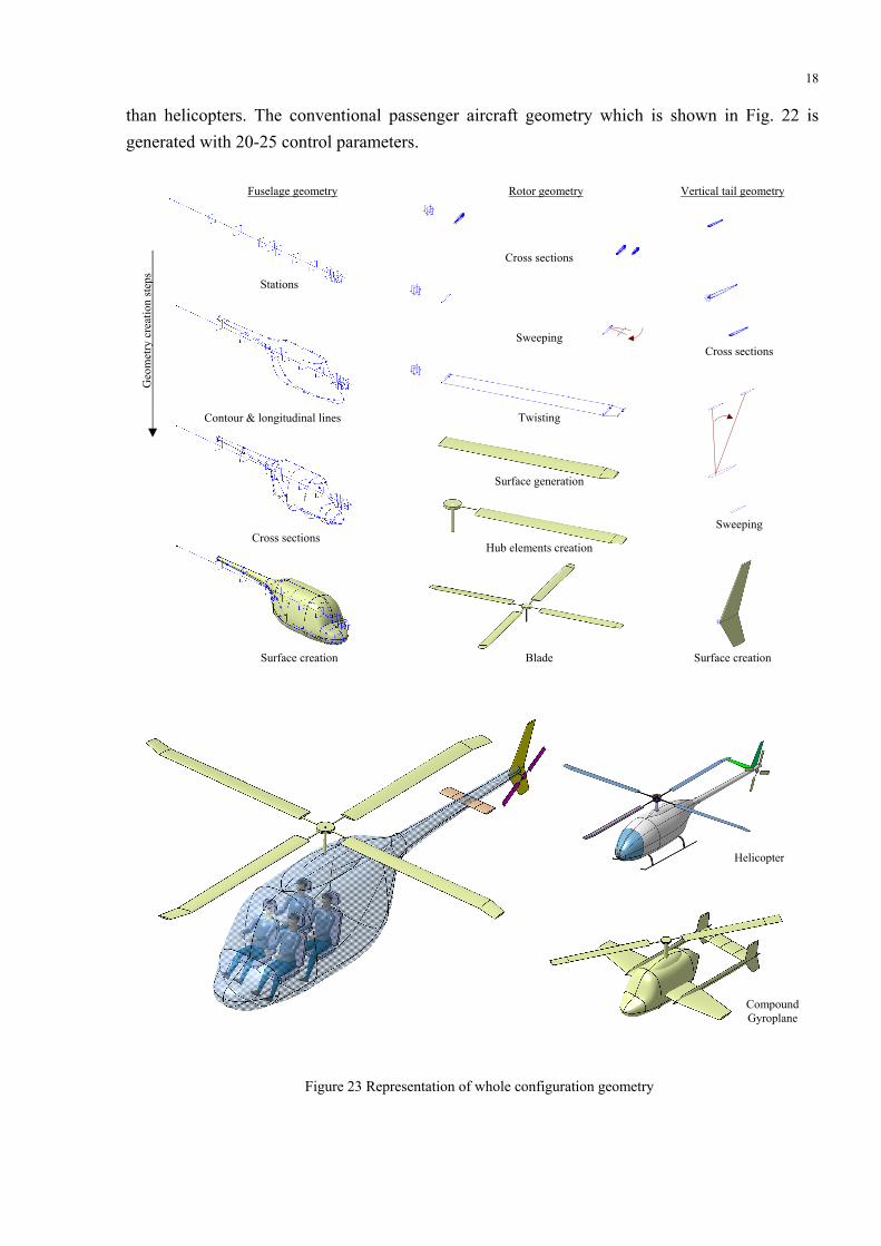
than helicopters. The conventional passenger aircraft geometry which is shown in Fig. 22 is generated with 20-25 control parameters.
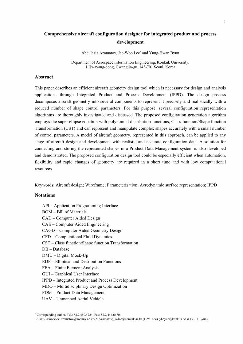
Figure 23 Representation of whole configuration geometry
Stations
Contour & longitudinal lines
Cross sections
Surface creation
Cross sections
Sweep angle
Twisting
Surface generation
Hub elements creation
Blade
Cross sections
Sweeping
Surface creation
Geo
met
ry c
reat
ion
step
s
Fuselage geometry Rotor geometry Vertical tail geometry
Sweeping
Helicopter
Compound Gyroplane

19
Fig. 23 shows steps of rotorcraft geometry design and configuration assembly. As shown in this figure, the shapes are very smooth, well distributed and realistic.
The main advantage of PCAD is availability of step-by-step geometry creation and modifying feature. A designer can make necessary decisions – modify and arrange the curves which later can be used to generate aircraft surface and whole configuration. PCAD does not require special CAD skills from the user, thus any user can build the necessary configuration in a very short time. Additional efficiency of PCAD is its open environment. It works under CATIA V5 CAD system [22]. The generated CAD data can serve in various other analysis programs or work together with other CAD software.
5. Conclusions
An interactive and generic aircraft geometry representation tool – Parameter-based Comprehensive Aircraft Designer (PCAD) for an IPPD framework was presented and some implementations were demonstrated.
Geometry representation methods – Class Function/Shape Function Transformations (CST) and Elliptic Distribution Function (EDF) method – were introduced. The EDF method was proposed to represent generic fuselage shapes.
PCAD allows the designer to create aircraft geometries in a step-by-step fashion and to manipulate them in real time. This tool also can be used to describe the relations between the performance and analysis modules in IPPD and MDO applications, which can deal with an aircraft’s weight, size, volume and performance.
An associative design application and PDM structure is presented as an example of helicopter blade assembly. The associative assembly approach gives good accuracy and a logical way to design and develop aircraft units.
The tools and approaches shown in this paper could be part of an aerospace-related CAD package or could be offered as a visualization tool for various frameworks, grid generation or analysis software. In addition, all the tools described above allow the design time and cost to be reduced, which is very important in aeronautics and aerospace development.
Acknowledgments
This work was supported by National Research Foundation of Korea Grant funded by the Korean Government (K2060100001), a grant T007F3510001-07F015400310 from the Aviation Safety R&D Program funded by the Ministry of Land, Transport and Maritime Affairs of the Korean government and Brain Korea-21 program (BK21). The authors greatly appreciate Mr. Amgad Salama’s helpful comments.

20
References
[1] Trapp JC, Sobiezsky H. Interactive Parametric Geometry Design. AIAA 1999-0829. Reno, NV, USA; 1999. [2] Sobieczky H. Parametric Airfoils and Wings. Notes on Numerical Fluid Mechanics 1998; 68:71-88. [3] Kulfan BM. Universal Parametric Geometry Representation Method. J Aircraft 2008; 45:142-158 [4] Kulfan BM. A Universal Parametric Geometry Representation Method – “CST”. AIAA Paper 2007-62. 45th
AIAA Aerospace Sciences Meeting and Exhibition. Reno, Nevada, USA; 2007. [5] Kulfan BM, Bussoletti JE. “Fundamental” Parametric Geometry Representations for Aircraft Component
Shapes. AIAA Paper 2006-6948. 11th AIAA/ISSMO Multidisciplinary Analysis and Optimization Conference. Portsmouth, Virginia, USA; 6-8 September 2006.
[6] Samareh JA. A Survey of Shape Parametrization Techniques. CEAS/AIAA/ICASE/ NASA Langley International Forum on Aeroelasticity and Structural Dynamics. Williamsburg, VA, USA; June 22-25 1999.
[7] Athanasopoulos M, Ugail H, Gonzáles Castro G. Parametric design of aircraft geometry using partial differential equations. Adv Eng Software 2009; 40:479-486.
[8] Sarakinos SS, Valakos IM, Nikolos IK. A software tool for generic parameterized aircraft design. Adv Eng Software 2007; 38:39-49.
[9] Rodriguez DL, Sturdza, P. A Rapid Geometry Engine for Preliminary Aircraft Design. AIAA Paper 2006-929. 44th AIAA Aerospace Sciences Meeting and Exhibition. Reno, Nevada, USA; 2006.
[10] Raymer D. RDS-Professional in Action: Aircraft Design on a Personal Computer. SAE/AIAA Paper 965567; Oct. 1996.
[11] Lu L-J, Myklebust A, War S. Integration of a Helicopter Sizing Code with a Computer-Aided Design System. J Amer Helicopter Soc 1987; Oct:16-27.
[12] Ledermann C, Hanske C, Wenzel J, Ermanni P, Kelm R. Associative parametric CAE methods in the aircraft pre-design. Aerosp Sci Technol 2005; 9:641-651.
[13] Ledermann C, Ermanni P, Kelm R. Dynamic CAD objects for structural optimization in preliminary aircraft design. Aerosp Sci Technol 2006; 10:601-610.
[14] Iqbal LU, Sullivan JP. Application of an Integrated Approach to the UAV Conceptual Design. AIAA 2008-144. Reno, Nevada, USA; Jan 7-10 2008.
[15] Alonso JJ, LeGresley P, Pereyra V. Aircraft design optimization. Mathematics and Computers in Simulation 2009; 79:1948-1958.
[16] Fudge DM, Zingg DW, Haimes R. A CAD-Free and CAD-Based Geometry Control System for Aerodynamic Shape Optimization. AIAA Paper 2005-451. 43rd AIAA Aerospace Sciences Meeting and Exhibit. Reno, Nevada, USA; January 10-13 2005.
[17] Fredericks WJ, Antcliff KR, Costa G, Deshpande N, Moore MD, San Miguel EA, Snyder AN. Aircraft Conceptual Design Using Vehicle Sketch Pad. AIAA Paper 2010-658. 48th Aerospace Sciences Meeting Including the New Horizons Forum and Aerospace Exposition. Orlando, Florida, USA, January 4-7 2010.
[18] Price M, Raghunathan S, Curran R. An integrated systems engineering approach to aircraft design. Progr Aerosp Sci 2006; 42:331-376.
[19] Mavris DN. Formulation of an IPPD Methodology for the Design of a Supersonic Business Jet. AIAA Paper 965591. 1st World Aviation Congress. Los Angeles, CA, USA; 1996.
[20] Richter T, Mechler H, Schmitt D. Integrated parametric aircraft design. ICAS Congress. Institute Aeronautical Engineering, TU Munich; 2002.
[21] Azamatov AI, Lee J-W, Byun Y-H, Kim S-H. Advanced Configuration Generation Technique for the Complex Aircraft Geometry. IEEE/ASME International Conference on Advanced Intelligent Mechatronics. Xi'an. China; July 2-5 2008.
[22] www.3ds.com/products/catia.