Upload lemien
View 217
Download 1
Embed Size (px) 344 x 292 429 x 357 514 x 422 599 x 487
Citation preview
Radial Diagram
Access and continuity
Planned care for chronic conditions and preventive care
Risk stratified care management
Patient and care giver engagement
Coordination of care across the medical neighborhood
Strategic use of practice revenue
Build practice analytic capability
Culture of improvement
Internal measurement and review
Continuous improvement of HIT
Data exchange
EHR-based quality reporting
Aligned payment reform
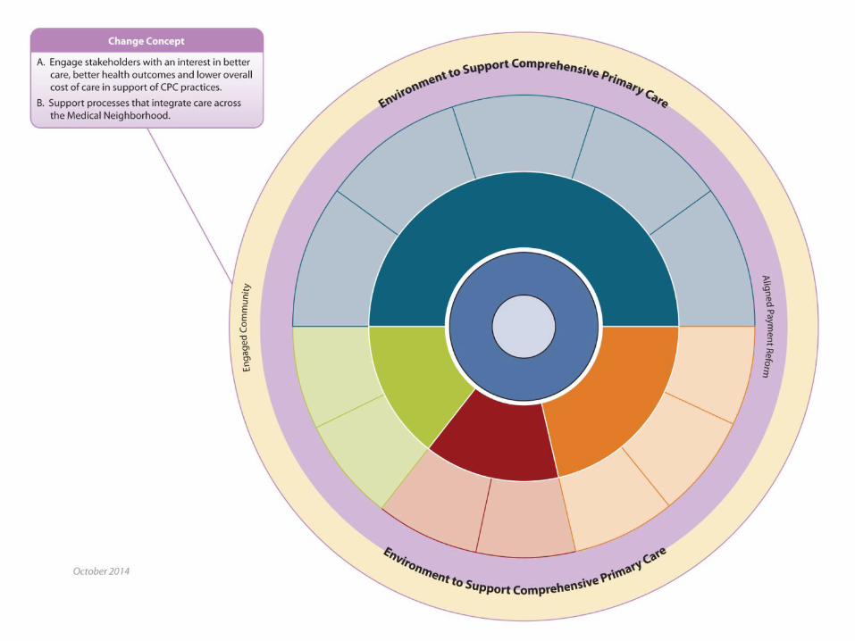
Engaged community
Programmable Logic Controller LS PLC Series · encoder (2 channels of Open ... (Ladder Diagram), SFC ... LS PLC Programmable Logic Controller - Programmable Logic
Example 1: Interior/exterior lighting of a residential propertycrouzetsales.com/pdf/ntr757-E_Application Library.pdf · BIT MULTIPLEXER ... Logic diagram (EN_1.pm2) Logic diagram
Programmable Logic Controllers (PLC) - Home - …technologyfuturae.webs.com/Automation/PLC 1.pdf · Programmable Logic Controllers (PLC) ... Different functions & Ladder diagram Examples
Interconnections for High-speed Digital Circuits ... diagram. Use of ... Internal structure of digital logic circuits, -Static electrical parameters of logic ... eed logic families:
LADDER DIAGRAM A ladder diagram is a means of graphically representing the logic required in a relay logic system. Rail Rung
CPU Board Logic Diagram CREATED BY: Richard Harvey 1J2 1J4
Prevention Redesign Initiative (PRI) Logic Model and Evaluation
LOGIC DIAGRAM: HALF ADDER - chettinadtech.ac.inchettinadtech.ac.in/storage/12-07-09/12-07-09-15-28-30-1582-Devil... · LOGIC DIAGRAM: HALF ADDER ... A half adder has two inputs for
LOGIC DIAGRAM COLD REHEAT SYS
PLC Hardware / Software - idc-online.com · 2019. 2. 4. · Ladder Diagram (RLD) logic language. Action Logic is the logic associated with a step, i.e., the logic, programmed by RLL
CAM ladder logic diagram
Apple Macbook PRO A1286 (Late 2008-Early 2009), Laptop Logic Board Schematic Diagram
Logic Diagram - Dakalia
61072618 Programmable Logic Controllers Diagram
Logic gate-diagram
RTL LOGIC REALIZATION USING LADDER DIAGRAM FOR ... · RTL LOGIC REALIZATION USING LADDER DIAGRAM FOR PROGRAMMABLE CONTROLLER output in the Ladder Diagram is represented by a circle
Memorex 651 Floppy Logic Diagram
ANSI-IsA S5.2-1981 Logic Diagram for Process Operation
ELECTRICAL DESIGN ENGINEER - Simon Fraser … DESIGN ENGINEER ... – Logic diagrams – Wiring & interconnection diagrams – Block diagrams. ... Logic Schematic Diagram Example
A-61x Series Programmable Logic Controller - proswede · A-61x Series Programmable Logic Controller ... Diagram (FBD)or Ladder Diagram (LAD) ... Encoder Stepping Motor Control
S M -J250N Logic Block Diagram
Evaluation and Logic Model Initiative - NCSRC · WestEd.org Evaluation and Logic Model Initiative Reflection, Improvement, Application: Making the Most of Logic Models WestEd March
A-61x Series Programmable Logic Controller · A-61x Series Programmable Logic Controller ... Diagram (FBD)or Ladder Diagram (LAD) ... Encoder Stepping Motor Control
4 TO 16 LINE DECODER/DEMULTIPLEXER - California … of... · M74HC154 3/12 LOGIC DIAGRAM This logic diagram has not be used to estimate propagation delays ABSOLUTE MAXIMUM RATINGS
krishnamoorthymca99.files.wordpress.com€¦ · Web viewBinary logic gates are explained with the help of logic diagram, block diagram and truth table. Basic laws of Boolean Algebra
2Basic Ladder Logic Programming - Weebly€¦ · 2Basic Ladder Logic Programming Chapter Topics: • Basic ladder logic symbols • Ladder logic diagram • Ladder logic evaluation
BOOLEAN LOGIC DESIGN - Open eClass ΤΕΙ Θεσσαλίας · BOOLEAN LOGIC DESIGN ... circuit diagram and ladder logic. ... There are some particular advantages of a PLC over digital
Obsolete Product(s) - Mouser Electronics fileObsolete Product(s) - Obsolete Product(s) M74HC173 3/12 LOGIC DIAGRAM This logic diagram has not be used to estimate propagation delays
LBI-39145 - CONTROL LOGIC/IF BOARD CMC-855 NOISE … · 2006. 12. 15. · LBI-39145 1. Figure 1 - Control Logic Section Block Diagram Figure 2 - 20.8 MHz IF Section Block Diagram
Preliminary Master Logic Diagram for ITER Operation