Embed Size (px)
Citation preview
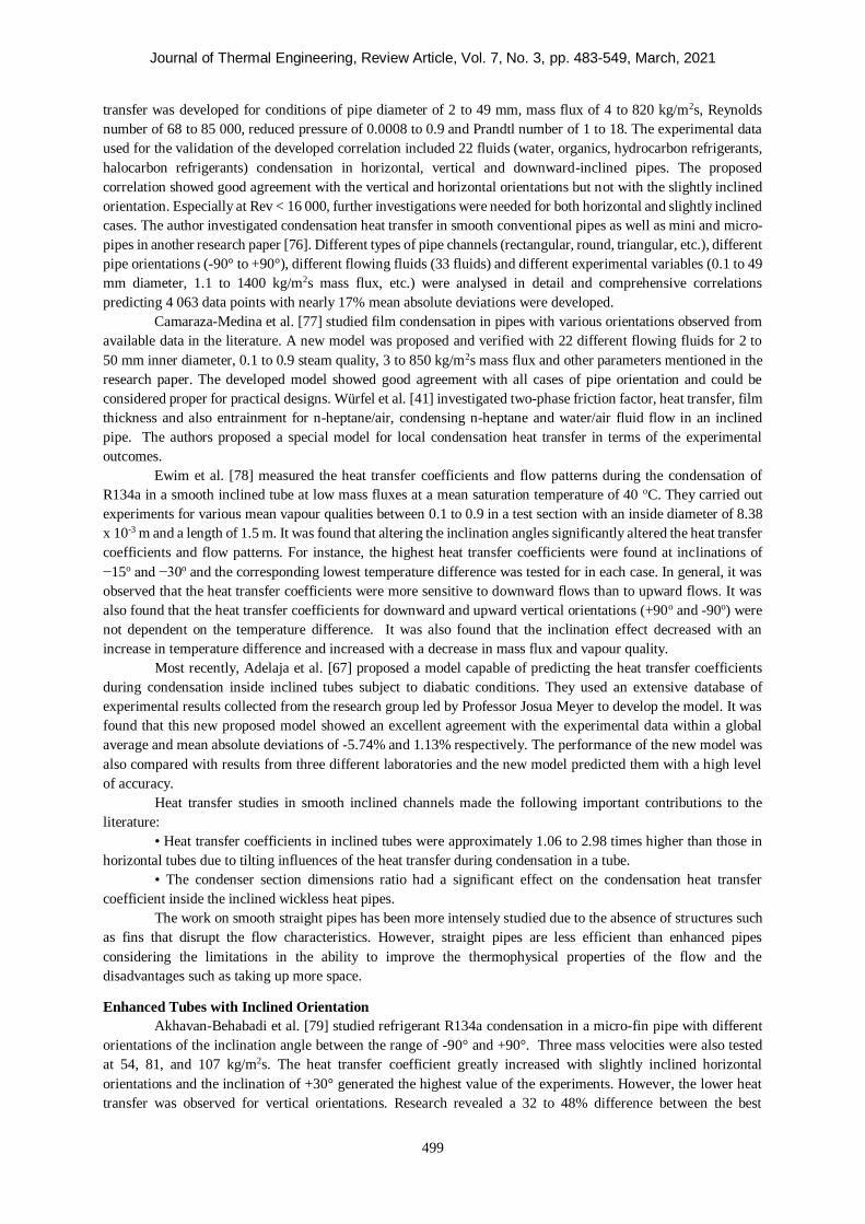
Journal of Thermal Engineering, Vol. 7, No. 3, pp. 483-549, March, 2021 Yildiz Technical University Press, Istanbul, Turkey
This paper was recommended for publication in revised form by Regional Editor Mohsen Sheikholeslami 1
Department of Mechanical Engineering, Yildiz Technical University, Istanbul, Turkey 2
Department of Mechanical Engineering, Istanbul Arel University, Istanbul, Turkey 3
Department of Mechanical and Aeronautical Engineering, University of Pretoria, Pretoria, South Africa 4
Department of Mechanical Engineering, King Mongkut’s University of Technology Thonburi, Bangkok, Thailand
*E-mail address: [email protected], [email protected], [email protected], [email protected],
[email protected], [email protected], [email protected]
Orcid id: 0000-0002-7297-7879, 0000-0002-7091-6175, 0000-0002-0095-829X, 0000-0002-5743-3937, 0000-0003-0256-3619,
0000-0002-3675-5494, 0000-0003-2648-6814
Manuscript Received 26 September 2020, Accepted 22 January 2021
COMPREHENSIVE REVIEW ON THE FLOW CHARACTERISTICS OF TWO-PHASE
FLOWS IN INCLINED TUBES
Hakan Karademir1*, Güven Özçelik2, Özgen Açıkgöz1, Ahmet Selim Dalkılıç1, İbrahim Timuçin İnce2, Josua
Meyer3, Somchai Wongwises4
ABSTRACT
This paper presents a comprehensive review of research works on condensation and boiling heat transfer
characteristics in horizontal, vertical and inclined tubes both smooth and enhanced. Although there are many
studies examining two-phase flows inside tubes, it is almost impossible to find such a comprehensive study for
two-phase flow in tubes. Moreover, while number of the studies concerning condensation or boiling inside tubes
are limited, the present study covers almost all studies of condensation and boiling inside inclined tubes. Previous
studies are classified into many subtitles according to configuration (horizontal, vertical or inclined) and roughness
(smooth or enhanced) as well as aim of the study (researching the effect of parameters on the heat transfer
coefficient, pressure drop or evaluation of prediction correlation). Such a wide range of classification and scope
have no done before. Condensation and boiling phenomena are of great importance in heat exchangers, cooling
systems, etc. due to their wide utilization in those devices. Additionally, two-phase flow and the associated heat
transfer are becoming increasingly important in industrial applications because the heat transfer coefficient in two-
phase flows is much higher than in single-phase flows. In this research, major topics such as heat transfer, pressure
drop, friction factor and void fraction were studied using active and passive techniques in the literature.
The fluids used in the reviewed studies diverse in a very wide range. For pure refrigerants (single
component-fluorocarbon refrigerant), R11, R12, R22, R32, R-113, R123, R-124, R125, R134, R134a, R142b,
R152a, R236fa, R245fa, R-600a, R1234ze, R1234yf and for zeotropic blend refrigerants, a mixture of two or more
components having different boiling points, R410A, R404A, R407C, R447A are used. As zeotropic blend
refrigerants, a mixture of two or more components that boil at the same temperature, R502. Besides, water (steam
for condensation), FC72, CFC 113, Propane, HFE 7000 (1-methoxyheptafluoropropane), R744 (CO2), and liquid
nitrogen are involved in researchers’ studies.
In the present review, effects of parameters on two-phase flow heat characteristics are evaluated. Based
on the evaluation, it can be drawn that inclination angle have significant effect on both condensation and boiling
heat transfer coefficient and pressure drop. On the other hand, it was found that vapour quality and roughness were
the main parameters affecting two-phase flow heat transfer characteristics. Effects of all parameters are discussed
in the corresponding section. When existing correlations in the literature on prediction flow boiling heat transfer
coefficient are evaluated, correlations proposed by Müller-Steinhagen and Heck [103] and Friedel [113] were to
be best for prediction well according to majority of researchers and for performance of prediction on pressure drop
correlation by Müller-Steinhagen and Heck [103] stood out.
Keywords: Flow Boiling, Flow Condensation, Two-Phase Flow Heat Transfer, Inclined Tubes, Heat
Transfer Coefficient, Pressure Drop, Comprehensive Review
Journal of Thermal Engineering, Review Article, Vol. 7, No. 3, pp. 483-549, March, 2021
484
CONTENTS
ABSTRACT ................................................................................................................................... 483
INTRODUCTION ........................................................................................................................................ 485
FLOW REGIME DETERMINATION CONDENSATION STUDIES ........................................................... 485
Introductory Remarks ............................................................................................................................... 485
Literature Studies ..................................................................................................................................... 486
PRESSURE DROP DETERMINATION CONDENSATION STUDIES ....................................................... 489
Introductory Remarks ................................................................................................................. 489
Horizontal and Vertical Orientations ........................................................................................... 490
Smooth Tubes with Inclined Orientation ..................................................................................... 492
Enhanced Tubes with Inclined Orientation .................................................................................. 493
HEAT TRANSFER COEFFICIENT DETERMINATION CONDENSATION STUDIES ............... 493
Introductory Remarks ................................................................................................................. 493
Horizontal and Vertical Orientations ........................................................................................... 494
Smooth Tubes with Inclined Orientation ..................................................................................... 497
Enhanced Tubes with Inclined Orientation .................................................................................. 499
FLOW REGIME DETERMINATION BOILING STUDIES ........................................................... 501
Introductory Remarks ................................................................................................................. 501
Literature Studies........................................................................................................................ 502
PRESSURE DROP DETERMINATION BOILING STUDIES ....................................................... 503
Introductory Remarks ................................................................................................................. 503
Horizontal and Vertical Orientations ........................................................................................... 503
Smooth Tubes with Inclined Orientation ..................................................................................... 506
Enhanced Tubes with Inclined Orientation .................................................................................. 506
HEAT TRANSFER COEFFICIENT DETERMINATION BOILING STUDIES ............................. 508
Introductory Remarks ................................................................................................................. 508
Horizontal and Vertical Orientations ........................................................................................... 509
Smooth Tubes with Inclined Orientation ..................................................................................... 513
Enhanced Tubes with Inclined Orientation .................................................................................. 514
ADVANTAGES OF USING INCLINED TUBES .......................................................................... 514
RESULTS AND DISCUSSION ...................................................................................................... 515
Effects of Parameters on Condensation Heat Transfer Characteristics ......................................... 515
Effects of the main parameters on the heat transfer coefficent ................................................. 515
Effects of the main parameters on the pressure drop-fricton factor .......................................... 517
Effects of Parameters on Boiling Heat Transfer Characteristics ................................................... 518
Effects of the main parameters on the heat transfer coefficient ................................................ 518
Effects of the main parameters on the pressure drop-friction factor ......................................... 520
CONCLUSION .............................................................................................................................. 521
THE FUTURE OF THE RESEARCHES IN THIS FIELD .............................................................. 522
NOMENCLATURE ....................................................................................................................... 522
REFERENCES ............................................................................................................................... 524
Journal of Thermal Engineering, Review Article, Vol. 7, No. 3, pp. 483-549, March, 2021
485
INTRODUCTION
Flow in pipes is the most widespread physical condition confronted in heating, cooling and
air-conditioning systems. Devices known as heat exchangers are the main components of these systems and the
primary source of this phenomenon. Lately, mini- and micro-devices especially have been of the utmost
significance. Mini- and microscale mechanical devices have the advantage of being removed easily as well as
being highly efficient. Thanks to these advantages, micro- and mini-heat exchangers have been utilised for a long
time. Because boiling and condensation occur in these exchangers, it is very important to understand the
phenomena of boiling and condensation.
Micro-channels have their essential advantages in heat exchangers. Thanks to having a larger contact area
per unit volume than that of macro-channels, micro-channels withstand higher pressure than macro-channels do.
Moreover, the heat transfer coefficient of micro-channels is much higher than that of macro-channels. Evaporative
compact heat exchangers made of micro-channels are used in numerous applications that require high heat transfer
through a restricted volume. These heat exchangers are operated for a microprocessor cooling application in a
micro-heat pump or a portable cooling device [1].
Studies on compact heat exchangers have been conducted continuously. It is predicted that the need for
higher heat dissipation per unit volume for these heat exchangers will increase in the near future, due to an
increasing need to cool technology devices like microprocessors. Therefore, more energy-efficient heat exchangers
are required to be made [2]. Condensation and flow boiling in narrow tubes could reach a higher rate of heat
transfer than for single-phase cooling, thanks to its latent heat of vaporization. For this purpose, various methods,
which are generally grouped as active and passive techniques, have been studied in numerous researches. External
forces like vibration, electrostatic fields and fluid additives are needed for active techniques whereas special
surface structures are the general improvement tool for passive techniques. This study focused on the passive
techniques for condensation and boiling in inclined pipes.
Enhancement in heat transfer technology is vital to improve energy efficiency [3]. Heat transfer
augmentation is completed successfully through adding enhanced heat transfer tubes thanks to their substantial
potential in improving thermal performance. In recent years, numerous enhanced tubes have been developed and
broadly used for cooling applications such as refrigeration, ventilation and many other fields.
Corrugated tubes are one of the passive techniques to improve the heat transfer coefficient. A corrugated
tube has corrugation on its surface that can improve heat transfer through generating turbulence and restraining
the progression of the thermal boundary layer. This augmentation in heat transfer is realised while a small increase
in friction factor is seen [4].
This paper consists of two parts. In the first part, studies of condensation and boiling inside inclined tubes
are reviewed (almost all the studies are experimental). The researcher reading this paper could find the studies of
the hydrodynamic and thermal parameters of the channels in which fluids condense and boil in the literature. These
parameters are the heat transfer coefficient, pressure drop, void fraction and flow patterns. The shape of the
channels reviewed is mostly smooth and enhanced. In the context of this general inference, the paper presents
recent improvements related to condensation and the boiling process in inclined pipes. Therefore, the paper should
be an important up-to-date literature review of condensation and the boiling process in inclined pipes.
FLOW REGIME DETERMINATION CONDENSATION STUDIES
Introductory Remarks
Condensation is one of the main physical events encountered in many heat transfer problems. Knowing
the flow regimes in the processes where two-phase flow occurs aids in finding a solution. Therefore, re-evaluations
of findings and new experimental numerical studies have resulted in comprehensive processing of these issues as
well as improvements in the literature.
In practice, heat transfer and pressure characteristics vary depending on the two-phase flow regime and
the internal structure of the pipe, gravity force, liquid-vapour distribution, etc.; in other words, factors known to
be components affecting the flow regime [5]. In the case of two-phase flow in a channel, factors such as surface
tension and shear force, which change depending on the inclination effect, lead to the emergence of different flow
regimes. This creates a heat and momentum transfer process that is physically more complicated, considering the
complex structure of the liquid-vapour flow [6]. If the system includes structures such as thin film flows, droplet
impingements or microfluidic, surface tension and wettability are also important as well as transport properties.
Although studies on these topics are insufficient in literature, it is known that the surface tension gain importance
Journal of Thermal Engineering, Review Article, Vol. 7, No. 3, pp. 483-549, March, 2021
486
in nanofluids used in energy systems and heat exchangers. For instance, surface tension can be used to understand
nanofluid boiling and stability of nanoparticles. In addition to the thermophysical properties, factors such as
surface tension and wettability will also contribute to the understanding of two-phase flow properties and heat
transfer characteristics. [7].
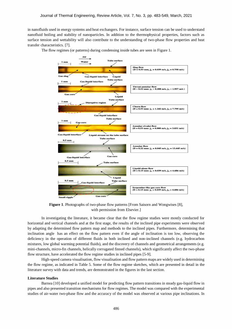
The flow regimes (or patterns) during condensing inside tubes are seen in Figure 1.
Figure 1. Photographs of two-phase flow patterns [From Saisorn and Wongwises [8],
with permission from Elsevier.]
In investigating the literature, it became clear that the flow regime studies were mostly conducted for
horizontal and vertical channels and at the first stage, the results of the inclined pipe experiments were observed
by adapting the determined flow pattern map and methods to the inclined pipes. Furthermore, determining that
inclination angle has an effect on the flow pattern even if the angle of inclination is too low, observing the
deficiency in the operation of different fluids in both inclined and non-inclined channels (e.g. hydrocarbon
mixtures, low global warming potential fluids), and the discovery of channels and geometrical arrangements (e.g.
mini-channels, micro-fin channels, helically corrugated finned channels), which significantly affect the two-phase
flow structure, have accelerated the flow regime studies in inclined pipes [5-9].
High-speed camera visualisation, flow visualisation and flow pattern maps are widely used in determining
the flow regime, as indicated in Table 5. Some of the flow regime sketches, which are presented in detail in the
literature survey with data and trends, are demonstrated in the figures in the last section.
Literature Studies
Barnea [10] developed a unified model for predicting flow pattern transitions in steady gas-liquid flow in
pipes and also presented transition mechanisms for flow regimes. The model was compared with the experimental
studies of air-water two-phase flow and the accuracy of the model was observed at various pipe inclinations. In
Journal of Thermal Engineering, Review Article, Vol. 7, No. 3, pp. 483-549, March, 2021
487
conclusion, for different flow regimes, the friction factor for the gas-liquid interface was observed using available
correlations with acceptable accuracy.
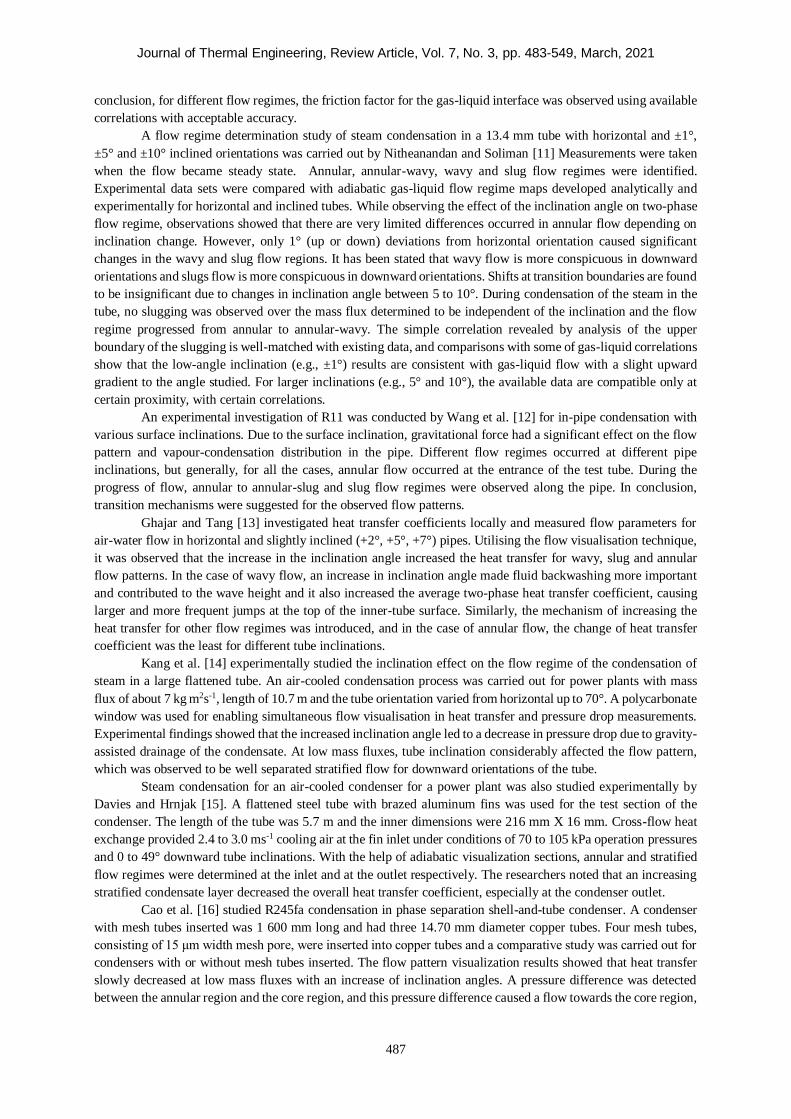
A flow regime determination study of steam condensation in a 13.4 mm tube with horizontal and ±1°,
±5° and ±10° inclined orientations was carried out by Nitheanandan and Soliman [11] Measurements were taken
when the flow became steady state. Annular, annular-wavy, wavy and slug flow regimes were identified.
Experimental data sets were compared with adiabatic gas-liquid flow regime maps developed analytically and
experimentally for horizontal and inclined tubes. While observing the effect of the inclination angle on two-phase
flow regime, observations showed that there are very limited differences occurred in annular flow depending on
inclination change. However, only 1° (up or down) deviations from horizontal orientation caused significant
changes in the wavy and slug flow regions. It has been stated that wavy flow is more conspicuous in downward
orientations and slugs flow is more conspicuous in downward orientations. Shifts at transition boundaries are found
to be insignificant due to changes in inclination angle between 5 to 10°. During condensation of the steam in the
tube, no slugging was observed over the mass flux determined to be independent of the inclination and the flow
regime progressed from annular to annular-wavy. The simple correlation revealed by analysis of the upper
boundary of the slugging is well-matched with existing data, and comparisons with some of gas-liquid correlations
show that the low-angle inclination (e.g., ±1°) results are consistent with gas-liquid flow with a slight upward
gradient to the angle studied. For larger inclinations (e.g., 5° and 10°), the available data are compatible only at
certain proximity, with certain correlations.
An experimental investigation of R11 was conducted by Wang et al. [12] for in-pipe condensation with
various surface inclinations. Due to the surface inclination, gravitational force had a significant effect on the flow
pattern and vapour-condensation distribution in the pipe. Different flow regimes occurred at different pipe
inclinations, but generally, for all the cases, annular flow occurred at the entrance of the test tube. During the
progress of flow, annular to annular-slug and slug flow regimes were observed along the pipe. In conclusion,
transition mechanisms were suggested for the observed flow patterns.
Ghajar and Tang [13] investigated heat transfer coefficients locally and measured flow parameters for
air-water flow in horizontal and slightly inclined (+2°, +5°, +7°) pipes. Utilising the flow visualisation technique,
it was observed that the increase in the inclination angle increased the heat transfer for wavy, slug and annular
flow patterns. In the case of wavy flow, an increase in inclination angle made fluid backwashing more important
and contributed to the wave height and it also increased the average two-phase heat transfer coefficient, causing
larger and more frequent jumps at the top of the inner-tube surface. Similarly, the mechanism of increasing the
heat transfer for other flow regimes was introduced, and in the case of annular flow, the change of heat transfer
coefficient was the least for different tube inclinations.
Kang et al. [14] experimentally studied the inclination effect on the flow regime of the condensation of
steam in a large flattened tube. An air-cooled condensation process was carried out for power plants with mass
flux of about 7 kg m2s-1, length of 10.7 m and the tube orientation varied from horizontal up to 70°. A polycarbonate
window was used for enabling simultaneous flow visualisation in heat transfer and pressure drop measurements.
Experimental findings showed that the increased inclination angle led to a decrease in pressure drop due to gravity-
assisted drainage of the condensate. At low mass fluxes, tube inclination considerably affected the flow pattern,
which was observed to be well separated stratified flow for downward orientations of the tube.
Steam condensation for an air-cooled condenser for a power plant was also studied experimentally by
Davies and Hrnjak [15]. A flattened steel tube with brazed aluminum fins was used for the test section of the
condenser. The length of the tube was 5.7 m and the inner dimensions were 216 mm X 16 mm. Cross-flow heat
exchange provided 2.4 to 3.0 ms-1 cooling air at the fin inlet under conditions of 70 to 105 kPa operation pressures
and 0 to 49° downward tube inclinations. With the help of adiabatic visualization sections, annular and stratified
flow regimes were determined at the inlet and at the outlet respectively. The researchers noted that an increasing
stratified condensate layer decreased the overall heat transfer coefficient, especially at the condenser outlet.
Cao et al. [16] studied R245fa condensation in phase separation shell-and-tube condenser. A condenser
with mesh tubes inserted was 1 600 mm long and had three 14.70 mm diameter copper tubes. Four mesh tubes,
consisting of 15 μm width mesh pore, were inserted into copper tubes and a comparative study was carried out for
condensers with or without mesh tubes inserted. The flow pattern visualization results showed that heat transfer
slowly decreased at low mass fluxes with an increase of inclination angles. A pressure difference was detected
between the annular region and the core region, and this pressure difference caused a flow towards the core region,
Journal of Thermal Engineering, Review Article, Vol. 7, No. 3, pp. 483-549, March, 2021
488
reducing the liquid film thickness at the bottom of the tube. When inclination angles varied from −30° to 30°, the
pressure difference decreased but the liquid-mesh contact area increased.
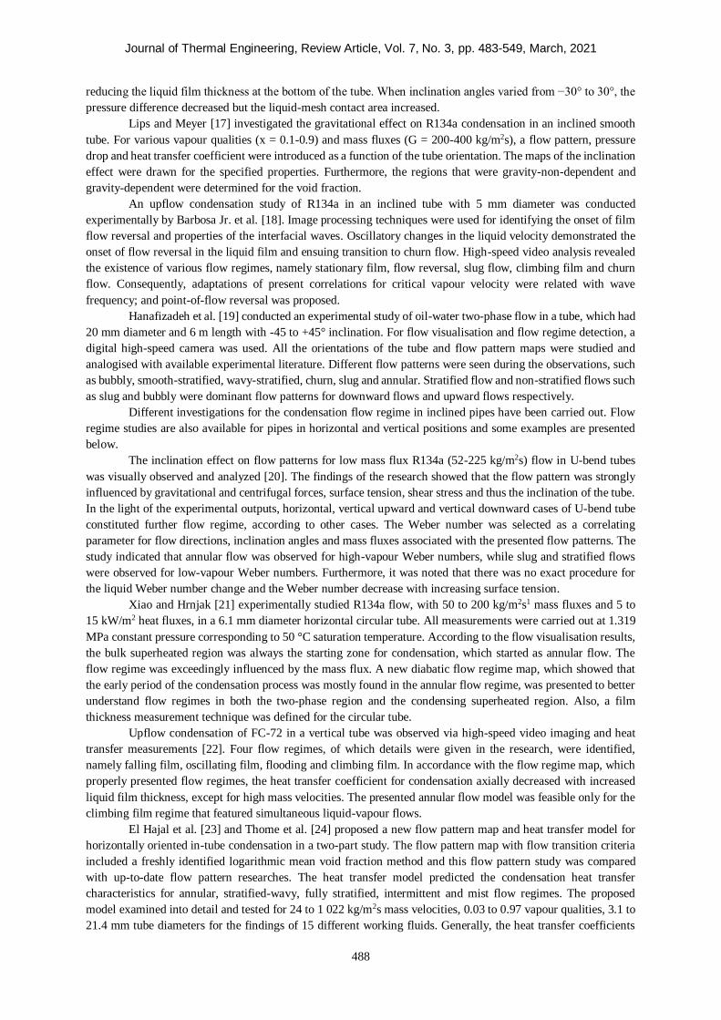
Lips and Meyer [17] investigated the gravitational effect on R134a condensation in an inclined smooth
tube. For various vapour qualities (x = 0.1-0.9) and mass fluxes (G = 200-400 kg/m2s), a flow pattern, pressure
drop and heat transfer coefficient were introduced as a function of the tube orientation. The maps of the inclination
effect were drawn for the specified properties. Furthermore, the regions that were gravity-non-dependent and
gravity-dependent were determined for the void fraction.
An upflow condensation study of R134a in an inclined tube with 5 mm diameter was conducted
experimentally by Barbosa Jr. et al. [18]. Image processing techniques were used for identifying the onset of film
flow reversal and properties of the interfacial waves. Oscillatory changes in the liquid velocity demonstrated the
onset of flow reversal in the liquid film and ensuing transition to churn flow. High-speed video analysis revealed
the existence of various flow regimes, namely stationary film, flow reversal, slug flow, climbing film and churn
flow. Consequently, adaptations of present correlations for critical vapour velocity were related with wave
frequency; and point-of-flow reversal was proposed.
Hanafizadeh et al. [19] conducted an experimental study of oil-water two-phase flow in a tube, which had
20 mm diameter and 6 m length with -45 to +45° inclination. For flow visualisation and flow regime detection, a
digital high-speed camera was used. All the orientations of the tube and flow pattern maps were studied and
analogised with available experimental literature. Different flow patterns were seen during the observations, such
as bubbly, smooth-stratified, wavy-stratified, churn, slug and annular. Stratified flow and non-stratified flows such
as slug and bubbly were dominant flow patterns for downward flows and upward flows respectively.
Different investigations for the condensation flow regime in inclined pipes have been carried out. Flow
regime studies are also available for pipes in horizontal and vertical positions and some examples are presented
below.
The inclination effect on flow patterns for low mass flux R134a (52-225 kg/m2s) flow in U-bend tubes
was visually observed and analyzed [20]. The findings of the research showed that the flow pattern was strongly
influenced by gravitational and centrifugal forces, surface tension, shear stress and thus the inclination of the tube.
In the light of the experimental outputs, horizontal, vertical upward and vertical downward cases of U-bend tube
constituted further flow regime, according to other cases. The Weber number was selected as a correlating
parameter for flow directions, inclination angles and mass fluxes associated with the presented flow patterns. The
study indicated that annular flow was observed for high-vapour Weber numbers, while slug and stratified flows
were observed for low-vapour Weber numbers. Furthermore, it was noted that there was no exact procedure for
the liquid Weber number change and the Weber number decrease with increasing surface tension.
Xiao and Hrnjak [21] experimentally studied R134a flow, with 50 to 200 kg/m2s1 mass fluxes and 5 to
15 kW/m2 heat fluxes, in a 6.1 mm diameter horizontal circular tube. All measurements were carried out at 1.319
MPa constant pressure corresponding to 50 °C saturation temperature. According to the flow visualisation results,
the bulk superheated region was always the starting zone for condensation, which started as annular flow. The
flow regime was exceedingly influenced by the mass flux. A new diabatic flow regime map, which showed that
the early period of the condensation process was mostly found in the annular flow regime, was presented to better
understand flow regimes in both the two-phase region and the condensing superheated region. Also, a film
thickness measurement technique was defined for the circular tube.
Upflow condensation of FC-72 in a vertical tube was observed via high-speed video imaging and heat
transfer measurements [22]. Four flow regimes, of which details were given in the research, were identified,
namely falling film, oscillating film, flooding and climbing film. In accordance with the flow regime map, which
properly presented flow regimes, the heat transfer coefficient for condensation axially decreased with increased
liquid film thickness, except for high mass velocities. The presented annular flow model was feasible only for the
climbing film regime that featured simultaneous liquid-vapour flows.
El Hajal et al. [23] and Thome et al. [24] proposed a new flow pattern map and heat transfer model for
horizontally oriented in-tube condensation in a two-part study. The flow pattern map with flow transition criteria
included a freshly identified logarithmic mean void fraction method and this flow pattern study was compared
with up-to-date flow pattern researches. The heat transfer model predicted the condensation heat transfer
characteristics for annular, stratified-wavy, fully stratified, intermittent and mist flow regimes. The proposed
model examined into detail and tested for 24 to 1 022 kg/m2s mass velocities, 0.03 to 0.97 vapour qualities, 3.1 to
21.4 mm tube diameters for the findings of 15 different working fluids. Generally, the heat transfer coefficients
Journal of Thermal Engineering, Review Article, Vol. 7, No. 3, pp. 483-549, March, 2021
489
were predicted by the model within a -20% accuracy for all flow regimes for 85% of the non-hydrocarbon database
(1 850 points) and 75% of the whole database (2771 points).
The literature review indicated that the flow pattern was significantly affected by inclination angle or the
gravitational effect in internal flows where condensation occurred and it was necessary to make detailed
observations especially in the transition boundaries between the flow regimes. Furthermore, the heat transfer and
pressure drop phenomena were also affected dramatically by the flow regime.
The increase in the inclination (for slightly inclined tubes) improved the two-phase heat transfer with the
rise of the waves creating larger and frequent splashes for the wavy flow, while for the slug flow, the two-phase
heat transfer improved with more intensive mixing effects depending on the change in the balance between the
buoyant force and the inertia force [13]. Under low mass flux conditions and for large flattened steam condensing
tubes, increasing the inclination angle caused a decrease in pressure drop; and the flow visualisation outputs
indicated that large void fraction and low vapour velocity occurred at high inclination angles [14]. For U-bend
tubes, stratified and stratified-wavy flow regimes appeared at low-vapour qualities, annular flow was observed at
high-vapour qualities where the effects of gravitational and centrifugal forces could be neglected. In the same
types of channels, with the increasing interfacial shear stress at high mass fluxes, the liquid separated from the
channel walls and this phenomenon provided a basis for more stable flow characteristics and disappearing slug
and slug/stratified-wavy flows [20].
In order to create more complicated results physically than those of research works on horizontal and
vertical channels, a periodic review is necessary of flow pattern investigations into inclined pipes where many
fluids are tested from water vapour in heat exchangers to FC-72 fluid used to maintain the heat balance of electronic
systems, as well as the refrigerants (R-134a, R245fa, etc.) used in thermodynamic cycles.
PRESSURE DROP DETERMINATION CONDENSATION STUDIES
Introductory Remarks
Although the pressure drop studies are especially important in piping systems, considering the effects on
both system cost and heat transfer performance, they have also gained importance in processes where heat transfer
occurs. In order to make a positive improvement to the stated cost and performance, the pressure drop in two-
phase flow systems in channels with different inclination angles has been investigated in many studies.
In condensation processes where two-phase flow occurs, experimental studies have shown that the
inclination, as well as the shape of the channel and its internal structure, also has a significant effect on pressure
drop characteristics. The pressure drop in a system basically includes three terms, namely the momentum pressure
drop caused by the channel's inner-outer kinetic energy difference, the friction pressure drop caused by the shear
stress between the liquid-vapour wall and the gravitational pressure drop that changes proportionally with the sinus
of the inclination angle. Compared with the horizontal position in constant mass flux conditions, the pressure drop
that increases with inclination in upward flows decreases with inclination in downward flows. The shear force is
the more determining factor due to the gravitational force that loses its dominant feature in high mass fluxes and
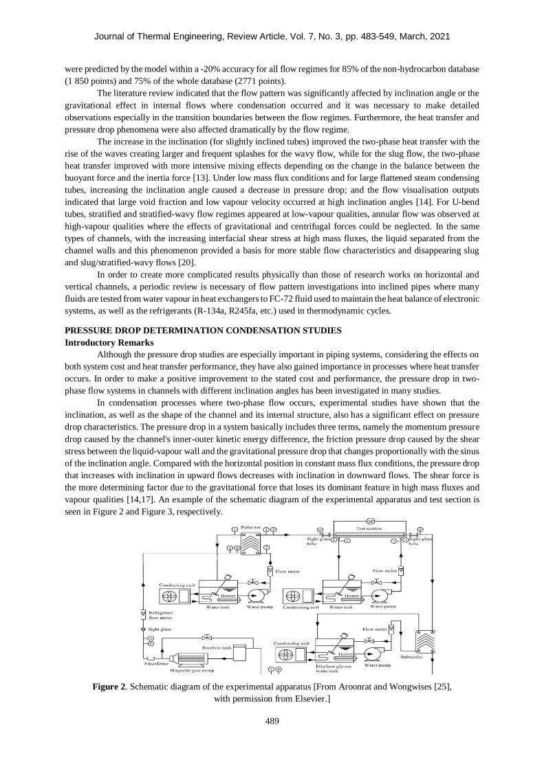
vapour qualities [14,17]. An example of the schematic diagram of the experimental apparatus and test section is
seen in Figure 2 and Figure 3, respectively.
Figure 2. Schematic diagram of the experimental apparatus [From Aroonrat and Wongwises [25],
with permission from Elsevier.]
Journal of Thermal Engineering, Review Article, Vol. 7, No. 3, pp. 483-549, March, 2021
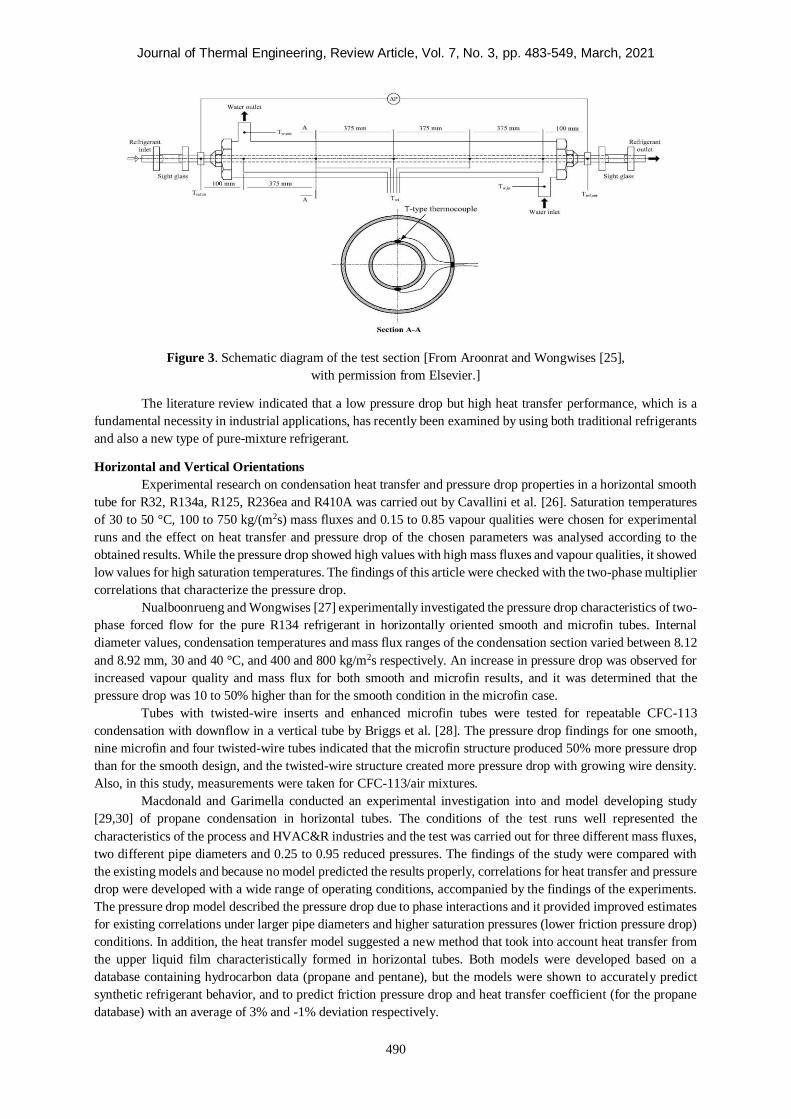
490
Figure 3. Schematic diagram of the test section [From Aroonrat and Wongwises [25],
with permission from Elsevier.]
The literature review indicated that a low pressure drop but high heat transfer performance, which is a
fundamental necessity in industrial applications, has recently been examined by using both traditional refrigerants
and also a new type of pure-mixture refrigerant.
Horizontal and Vertical Orientations
Experimental research on condensation heat transfer and pressure drop properties in a horizontal smooth
tube for R32, R134a, R125, R236ea and R410A was carried out by Cavallini et al. [26]. Saturation temperatures
of 30 to 50 °C, 100 to 750 kg/(m2s) mass fluxes and 0.15 to 0.85 vapour qualities were chosen for experimental
runs and the effect on heat transfer and pressure drop of the chosen parameters was analysed according to the
obtained results. While the pressure drop showed high values with high mass fluxes and vapour qualities, it showed
low values for high saturation temperatures. The findings of this article were checked with the two-phase multiplier
correlations that characterize the pressure drop.
Nualboonrueng and Wongwises [27] experimentally investigated the pressure drop characteristics of two-
phase forced flow for the pure R134 refrigerant in horizontally oriented smooth and microfin tubes. Internal
diameter values, condensation temperatures and mass flux ranges of the condensation section varied between 8.12
and 8.92 mm, 30 and 40 °C, and 400 and 800 kg/m2s respectively. An increase in pressure drop was observed for
increased vapour quality and mass flux for both smooth and microfin results, and it was determined that the
pressure drop was 10 to 50% higher than for the smooth condition in the microfin case.
Tubes with twisted-wire inserts and enhanced microfin tubes were tested for repeatable CFC-113
condensation with downflow in a vertical tube by Briggs et al. [28]. The pressure drop findings for one smooth,
nine microfin and four twisted-wire tubes indicated that the microfin structure produced 50% more pressure drop
than for the smooth design, and the twisted-wire structure created more pressure drop with growing wire density.
Also, in this study, measurements were taken for CFC-113/air mixtures.
Macdonald and Garimella conducted an experimental investigation into and model developing study
[29,30] of propane condensation in horizontal tubes. The conditions of the test runs well represented the
characteristics of the process and HVAC&R industries and the test was carried out for three different mass fluxes,
two different pipe diameters and 0.25 to 0.95 reduced pressures. The findings of the study were compared with
the existing models and because no model predicted the results properly, correlations for heat transfer and pressure
drop were developed with a wide range of operating conditions, accompanied by the findings of the experiments.
The pressure drop model described the pressure drop due to phase interactions and it provided improved estimates
for existing correlations under larger pipe diameters and higher saturation pressures (lower friction pressure drop)
conditions. In addition, the heat transfer model suggested a new method that took into account heat transfer from
the upper liquid film characteristically formed in horizontal tubes. Both models were developed based on a
database containing hydrocarbon data (propane and pentane), but the models were shown to accurately predict
synthetic refrigerant behavior, and to predict friction pressure drop and heat transfer coefficient (for the propane
database) with an average of 3% and -1% deviation respectively.
Journal of Thermal Engineering, Review Article, Vol. 7, No. 3, pp. 483-549, March, 2021
491
Kim et al. [31] conducted research into FC-72 condensation for parallel micro-channels with 29.9 cm
length and 1 mm hydraulic diameter. Mass fluxes of 68 to 367 kg/m2s and saturation temperatures of 57.2 to 62.3
°C were determined as operating conditions for the flowing fluid. A comprehensive pressure model, which
included various working parameters, was presented for pressure drop characteristics. Consequently, separated
flow models predicted the results more accurately than the homogeneous flow model and the adiabatic and
microchannel results were better predicted by separated models than the boiling and macro-channel results.
The condensation flow characteristics of various refrigerants (R22, R134a and R410A) flowing in a
micro-tube with 1,220 mm length and 1.77 mm inner diameter were studied experimentally [32]. Tests applied to
40 °C saturation temperature and 450 to 1,050 kg/m2s heat fluxes. The pressure drop of R134a was higher than for
R22 and R410A for the same mass flux. Also, a new model for pressure drop, which included a new factor C
(predicting result mean and average deviations of 2.31% and -8.7% respectively), was presented.
Condensation of R152a in a 1.152 mm diameter circular channel and of 0.952 mm hydraulic diameter
rectangular channel was investigated experimentally by Liu et al. [33] Different mass fluxes, vapour qualities and
saturation temperatures were selected for conducted tests and the effects of these parameters together with channel
geometry on pressure drop properties were observed. The findings indicated that the pressure drop increased with
increasing vapour quality and mass flux, whereas the pressure drop decreased with increasing saturation
temperature and channel geometry almost not important for low mass fluxes. The results were analogised with
theoretical and empirical correlations and the prediction qualities of these models were tested for the present
experimental findings.
For a counter flow concentric double-tube heat exchanger model, the flow characteristics of R134a
condensation in a smooth tube and a corrugated tube with 8.7 inner dimensions were investigated experimentally
by Laohalertdecha and Wongwises [34]. 21.2 mm inner diameter copper tube was tested at 40 to 50 °C saturation
temperatures, 200 to 700 kg/m2s mass fluxes and two different mass fluxes (5 and 10 kW/m2) for three different
corrugation pitches and one fixed corrugated depth 5.08, 6.35, 8.46 and 1.5 mm, respectively. The results of
smooth and corrugated cases indicated that corrugation pitches had a considerable effect on the pressure drop
increment.
The effects of twisted tapes on the pressure drop characteristics of R-404A condensation were studied by
Salimpour and Yarmohammadi [35] in the case of a counter flow heat transfer process. The refrigerant flowed
through the inner side of the tube, while cooling water flowed through the annulus side of the tube. Five different
cases including smooth and twisted-tape situations were tested for various vapour qualities and mass fluxes.
According to the authors, the twisted-tape cases created 89 to 239% higher pressure drop than for smooth case. In
addition, a new correlation was developed for pressure drop prediction and this model determined the experimental
data with ±20% accuracy.
The influence of coiled-wire inserts on the pressure drop was analysed experimentally [36] for convective
condensation of R-404A flow in one smooth case and five coiled-wire insert cases. Six different vapour qualities
were tested for each mass flux and accompanied by outputs, it was determined that the pressure drop for the coiled-
wire insert case was 1200% higher than the pressure drop for the smooth case.
The pressure drop studies of horizontal and vertical channels made the following important contributions
to the literature:
• For propane condensing in horizontal pipes with 7.75 and 14.45 mm inner diameter and specified
conditions, the pressure drop increased with increasing mass flow and vapour quality, while the rising temperature
decreased for the tube diameter [29].
• In order to improve the pressure drop correlation, flow visualisation studies used the horizontally
oriented flow data of hydrocarbon condensation, which covered a wide range of operating conditions. The model,
valid for 6 to 19 mm internal diameter, also explained additional friction pressures created by phase interactions
[30].
• While the pressure drop increased with increasing mass flux in FC-72 condensing flow in square-shaped
horizontally located 1 mm diameter micro-channels, the pressure drop decreased due to the flow deceleration
caused by increasing the mass velocity of cooling water [31]. Similar trends were observed in studies where
different fluids (R22, R134a, R152a, R404a, R410a, etc.) and different channel geometries (smooth, corrugated,
twisted-tape inserts, etc.) were experimentally studied [32-36].
Journal of Thermal Engineering, Review Article, Vol. 7, No. 3, pp. 483-549, March, 2021
492
Smooth Tubes with Inclined Orientation
Although the hydrodynamic characteristics of condensation in the pipe have been studied mostly by using
horizontal pipes, extensive studies have been conducted in inclined pipes in recent years. Lips and Meyer [37]
investigated pressure drop and void fraction for different vapour qualities and mass fluxes of R134a flow in a pipe
of different inclinations. The authors compared the findings with correlations in the literature and presented those
correlations suitable for vertical upward flows but not for downward flows. For a restricted area with stratified
flow, it was observed that the results of the slightly inclined pipe showed good agreement with the correlations.
Furthermore, they stated that momentum and gravitational pressure drop should be known in order to know the
void ratio. Considering the outcomes of this study, a more detailed investigation was conducted by Lips and Meyer
[38] into stratified flow. Capillary forces and gravitational forces were considered for the determination of the
liquid-vapour distribution in the pipe. The researchers proposed a mechanistic model for stratified flow and they
pointed out that there was a need for the modelling of intermittent flows in upward pipes to fully understand the
influence of gravitational forces on inclined two-phase flows.
A new heat transfer model package, which consisted of a momentum conservation model, flow regime
prediction model and interface shape prediction model, was developed by Ahn et al. [39]. Upper and lower parts
of the pipe were mechanically considered under separate flow conditions. When the void fraction was calculated
using the developed methodology, the permanency of the values was provided during the transition to different
flow regimes. The effect of gravity was considered, and the proposed model predicted the void fraction within 5%
of the mean deviation. Ahn et al. [40] investigated condensation characteristics in an inclinable circular pipe and
proposed a condensation model. The researchers conducted 21 tests by changing the inclination angle, steam flow
rate and inlet pressure. A correlation was proposed that correlated the two-phase multipliers and the void fraction.
The new model was found to be consistent with the condensation experimental data.
Hydrodynamic characteristics were investigated by Würfel et al. [41] for two-phase flow, which included
n-heptane/air, condensing n-heptane and water/air fluids in an inclined pipe. Special models were proposed for
determining the flow characteristics and these were compared with existing literature. The researchers concluded
that mass transfer intensity became effective on two-phase friction factor calculation and should not be neglected
in experimental researches.
Laboratory experiments were conducted by Grolman and Fortuin [42] in horizontal and inclined pipes
with different pipe orientations (-3° to +6°) and different experimental variables (15/26/51 mm diameter, 0 to 0.42
liquid hold-up, 0 to 0.06 m/s superficial liquid velocity, etc.). Discrete correlations were formulated by the authors
such as liquid-to-wall friction factor, interfacial friction factor and wetted perimeter. Preliminary studies of this
subject had been done by Grolman [43] before. On the whole, the data of 2400 well-controlled experiments were
properly calculated by the introduced method.
Two different models for wall shear stresses and 22 different correlations for the interfacial friction
factor, which included newly proposed ones, were studied by Ottens et al. [44]. The calculated results of the
developed models were compared with experimental databases consisting of 3 981 measurements. The
experimental range of properties varied with pipe diameter of 12.7 to 95.3 mm, density of 996 to 1120 kg/m3,
viscosity of 0.000852 to 0.092 Pa·s, inclination angle of -3° to +6°, etc. The authors pointed out that the separated
flow model and coupling of the interfacial friction factor to the wave velocity produced better results.
For hydrodynamic characteristics of two-phase flow in an inclined pipe (inclination angles from -90° to
90°), a unified model was developed and validated in a two-part study by Zhang et al. [45-46].The experimental
outcomes were obtained with varied diameters of test pipe, physical properties of fluid, flow rates and flow
patterns. Good agreement was achieved with predicted pressure gradient, liquid hold-up, slug characteristics and
flow pattern transitions. The classification of the flow pattern was simplified and compared with two-phase flow
at near-horizontal and upward orientations. Two-phase flow at vertically downward orientation was not
investigated sufficiently.
Woldesemayat and Ghajar [47] conducted a detailed study which consisted of comparison of 68 void
fraction correlations on the basis of 2845 points of data, of which 1542 were for inclined, 900 for horizontal and
403 for vertical pipe set-ups from previous studies. The doctoral thesis of Woldesemayat [48] provides necessary
knowledge about previous investigations and a wide range of data sets. For the entire void fraction database, best-
performing correlations were developed on the basis of the drift flux model. A modified void fraction correlation
was developed introducing proper physical parameters.
Journal of Thermal Engineering, Review Article, Vol. 7, No. 3, pp. 483-549, March, 2021
493
Ewim and Meyer [49] measured the pressure drop at low mass fluxes (50, 75 and 100 kg/m2s) in smooth
inclined tubes with an inside diameter of 8.38 x 10⁻³ m. They conducted their investigation at different mean vapour
qualities and temperature differences at an average saturation temperature of 40 oC. It was found that the measured
pressure drops increased with an increase in mass flux, temperature difference and vapour quality. They also found
that the lowest and highest measured pressure drops were obtained during the downward and upward flows
respectively.
Pressure drop studies of smooth inclined channels made the following important contributions to the
literature:
• During the convective condensation of the R134a refrigerant, the increasing inclination and decreasing
vapour qualities increased the pressure drop for the inclined orientation, while the reduced vapour qualities reduced
the pressure drop for the horizontal and vertical upflow-downflow conditions [37].
• The effect of the mass transfer phenomenon on the two-phase friction coefficient and the effect of liquid
hold-up and pressure gradient on the system performance under examination are important in inclined pipes [41,
42].
• In the developed flow models, examination of the wave velocity with the interfacial friction and
verification of the flow pattern transitions with features such as liquid hold up and pressure gradient generated
more accurate results [44, 45].
Existing studies should be evaluated by collating the effects of inclination angle on system pressure. This
will provide a more accurate observation that takes into account all parameters of the process.
Enhanced Tubes with Inclined Orientation
Mozafari et al. [50] observed R-600a condensation and pressure characteristics in a helically inclined
(+30°, +60°, +90°) counter flow heat exchanger. A 305 mm diameter coiled-tube heat exchanger model had
properties of 35 mm pitch, 210 mm height and six turns of coil and tests conducted for both helical and straight
heat exchangers at two different saturation temperatures (38.5 and 47 °C), 155-265.5 kg/m2s mass fluxes and 0.11
to 0.78 vapour qualities. How heat transfer and pressure drop changed with inclination angle, vapour quality and
mass flux was examined and the highest heat transfer at 30° and the lowest heat transfer at 90° were observed,
while the maximum pressure drop was measured for the horizontal case. The performance index gave the following
important outputs: 15 to 41% higher for the horizontal case than for the 90° inclination case; for the helically coiled
case, the pressure drop and the mean heat transfer coefficient increased in terms of the straight condenser between
the range of 33 and 157% and 24 and 165% respectively.
Li et al. [51] numerically observed hydrocarbon mixture upflow condensation characteristics in smooth
and spirally enhanced pipes with a 10° inclination angle. They developed a numerical model and scrutinised the
effects of geometrical variables. The increments of the heat transfer for spiral grooved, square corrugated and
sinusoidal corrugated were 1.206 to 1.804, 0.934 to 2.052 and 1.103 to 2.216 times higher than for the smooth
case, while the increments of the pressure drop for spiral grooved, square corrugated and sinusoidal corrugated
were 0.851 to 3.587, 1.805 to 10.930 and 1.272 to 7.176 times higher than for the smooth case. The comprehensive
heat transfer enhancement factor (CHF) was introduced, which indicated how heat transfer changed with geometric
improvement. For the sinusoidal and square cases, an increase of corrugation height increased the CHF, whereas
for the spiral grooved case, an increase of corrugation height decreased the CHF. However, it was observed that
an increase of corrugation pitch influenced the CHF differently throughout the pipes.
At present, there is a dearth of research on pressure drop for condensation in inclined enhanced pipes in
the literature. Current research has indicated that pressure drop is significantly affected by flow properties such as
mass flux, steam quality (in helical tubes) and geometric parameters such as groove height and groove pitch (in
spiral tubes).
HEAT TRANSFER COEFFICIENT DETERMINATION CONDENSATION STUDIES
Introductory Remarks
In practice, one of the most required property in two-phase flows is the heat transfer phenomenon, where
phase changes are present, significantly affecting flow characteristics and fluid properties. Condensation heat
transfer characteristics in inclined channels have been provided in numerous studies.
The main physical reflection of the channel inclination (relative to the horizontal) is the increase in the
downstream velocity and the decrease in the upstream velocity with the change of gravitational force. Factors such
Journal of Thermal Engineering, Review Article, Vol. 7, No. 3, pp. 483-549, March, 2021
494
as mass flux, temperature and vapour quality, which affect properties such as flow velocity (Reynolds number),
interface shear stress (frictional pressure drop), void fraction in two-phase flow, and have been studied in many
studies, and their reflections on heat transfer, have been observed. Fluid type, channel geometry and channel
inclination have been evaluated as variable parameters in these studies. It has been shown in many researches that
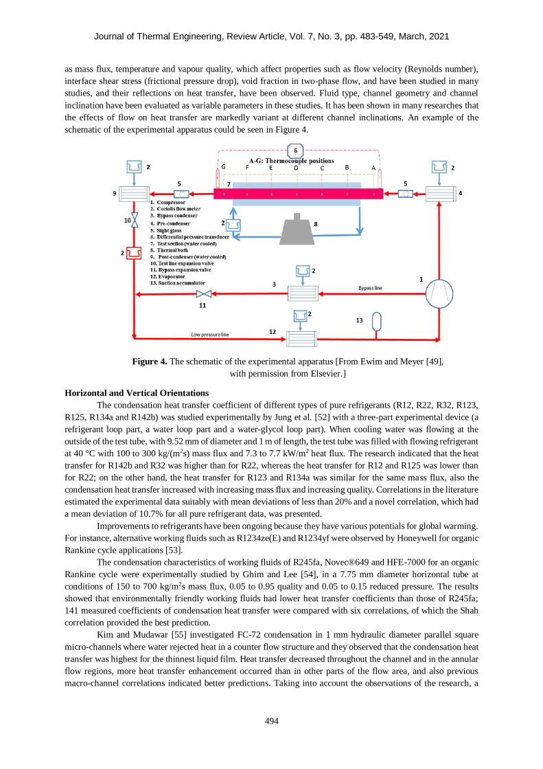
the effects of flow on heat transfer are markedly variant at different channel inclinations. An example of the
schematic of the experimental apparatus could be seen in Figure 4.
Figure 4. The schematic of the experimental apparatus [From Ewim and Meyer [49],
with permission from Elsevier.]
Horizontal and Vertical Orientations
The condensation heat transfer coefficient of different types of pure refrigerants (R12, R22, R32, R123,
R125, R134a and R142b) was studied experimentally by Jung et al. [52] with a three-part experimental device (a
refrigerant loop part, a water loop part and a water-glycol loop part). When cooling water was flowing at the
outside of the test tube, with 9.52 mm of diameter and 1 m of length, the test tube was filled with flowing refrigerant
at 40 °C with 100 to 300 kg/(m2s) mass flux and 7.3 to 7.7 kW/m2 heat flux. The research indicated that the heat
transfer for R142b and R32 was higher than for R22, whereas the heat transfer for R12 and R125 was lower than
for R22; on the other hand, the heat transfer for R123 and R134a was similar for the same mass flux, also the
condensation heat transfer increased with increasing mass flux and increasing quality. Correlations in the literature
estimated the experimental data suitably with mean deviations of less than 20% and a novel correlation, which had
a mean deviation of 10.7% for all pure refrigerant data, was presented.
Improvements to refrigerants have been ongoing because they have various potentials for global warming.
For instance, alternative working fluids such as R1234ze(E) and R1234yf were observed by Honeywell for organic
Rankine cycle applications [53].
The condensation characteristics of working fluids of R245fa, Novec®649 and HFE-7000 for an organic
Rankine cycle were experimentally studied by Ghim and Lee [54], in a 7.75 mm diameter horizontal tube at
conditions of 150 to 700 kg/m2s mass flux, 0.05 to 0.95 quality and 0.05 to 0.15 reduced pressure. The results
showed that environmentally friendly working fluids had lower heat transfer coefficients than those of R245fa;
141 measured coefficients of condensation heat transfer were compared with six correlations, of which the Shah
correlation provided the best prediction.
Kim and Mudawar [55] investigated FC-72 condensation in 1 mm hydraulic diameter parallel square
micro-channels where water rejected heat in a counter flow structure and they observed that the condensation heat
transfer was highest for the thinnest liquid film. Heat transfer decreased throughout the channel and in the annular
flow regions, more heat transfer enhancement occurred than in other parts of the flow area, and also previous
macro-channel correlations indicated better predictions. Taking into account the observations of the research, a
Journal of Thermal Engineering, Review Article, Vol. 7, No. 3, pp. 483-549, March, 2021
495
new correlation, which had a perfect predictive capacity for both FC-72 and inspected database of channels, was
proposed.
Oh and Son [56] conducted experiments of R22, R134a and R410a condensation in a circular micro-tube,
in 450 to 1 050 kg/m2s mass flux and 40 °C saturation temperature conditions. For the same mass flux,
condensation heat transfer of R410a was more effective than that of other refrigerants, whereas R22 and R134
showed an almost similar effect on heat transfer. The proposed correlations for a large diameter tube and single
circular micro-tube predicted heat transfer poorly, and thus the authors concluded that it was necessary to propose
a proper correlation for a single circular micro-tube.
For the range of 103 to 490 kg/m2s mass fluxes and 31 to 48 ℃ saturation temperatures in laboratory
conditions, Yang and Jia [57] experimentally conducted upflow condensation tests of R410a with four different
length vertical tubes, which had 8.02 mm inner diameter. The effects of length, condensing temperature and mass
flux on condensation were examined for the test zone where the average steam qualities of 0.91 and 0.98 were
captured. The observed results were compared with some of the existing correlations. As a result of experimental
data that did not match the correlations with a certain percentage error, an original modified correlation was
proposed and results were obtained with a deviation of ± 15%.
Condensing heat transfer properties for R744/R32/R1234ze (E) refrigerant mixture with low global
warming effect were examined by Kondou et al. [58] for different saturation temperatures, mass fluxes and heat
fluxes in horizontal micro-fin tubes and comparisons were made with a mixture of R32/R1234ze (E) for different
refrigerant percentages. For an average saturation temperature of 40 °C, mass flow of 200 kg/m2s and heat flux of
10 kW/m2, the condensation heat transfer coefficient of mixture R744/R32/R1234ze (E) (9/29/62 mass%) was
identified lower than for mixture R32/R1234ze(E) (40/60 and 30/70 mass%). In addition, single-component
refrigerants were also studied, and the experimental pressure gradient was found to be compatible with the
predictions recommended for single-component cases, which could also predict the pressure gradient of mixtures.
In all cases, the pressure gradients remained nearly the same in measurement uncertainty.
For the R1234yf refrigerant, which has a global warming potential of less than 1 and can be useful for
future engineering technologies, condensation characteristics were studied in a micro-fin pipe at 0.2 to 0.95 vapour
qualities, 100 to 1 000 kg /m2s mass fluxes and 30 and 40 °C saturation temperatures [59]. Experimental results
showed that mass flux and vapour quality properties had strong effects on heat transfer and it was determined that
the heat transfer coefficient increased with the increase of these two properties. Furthermore, the friction pressure
gradient increased with mass flux in the case of constant vapour quality, while it varied with vapour quality in the
case of constant mass flux.
In the conditions of 5.7 to 5.9 bar saturation pressure, 20 to 100 kg/m2s mass flux and 1.7 to 5.3 kW/m2
heat flux, Arslan and Eskin [60] experimentally studied vapour condensation of pure R134A in a helically inclined
(18 °C) micro-fin tube. They also observed the effectiveness of temperature difference and mass flux on heat
transfer in terms of experimental data. Some of the outcomes of the study were that the fins performed as
turbulence increasing in all experiments, the heat transfer enhancement ratio (1.59-1.71) was always higher than
the heat transfer area enhancement factor (1.55), and condensate Nusselt number was found to be independent of
the temperature difference in conditions where the temperature difference was higher than 2.58 °C. The most-used
correlations in the literature for micro-fin tubes were applied to the experimental data and the most appropriate
correlations estimated the results with an absolute mean deviation of 17% to 19%.
Heat transfer and pressure characteristics for R410A and R22 refrigerants flowing in a herringbone-type
micro-fin tube were investigated together with the data of the helical micro-fin and plain tube by Miyara et al.
[61]. In the region where high mass flux was available, higher heat transfer provided in the herringbone-type tube
than for the helical micro-fin case, whereas heat transfer showed the opposite character for the low mass flux
region. Moreover, the pressure drop was higher in the herringbone micro-fin tube than in the helical micro-fin
tube. Preliminary correlations were proposed for the herringbone-type pipe because for the heat transfer coefficient
and pressure drop, the present correlations agreed well with the findings for the helical micro-fin tube, while the
findings obtained for the herringbone-type tube were higher than those predicted values.
For a straight tube and nine corrugated tubes (for different pitches and depths) in conditions of mass
fluxes of 187 to 561 kg/m2s, steam qualities of 0.18 to 0.85 and condensation temperatures of 29.2 to 35.8 °C, the
characteristics of R-404A refrigerant were experimentally studied in a 8.7 mm inner diameter channel inside the
test section designed as a 1 m length, water-cooled, horizontal counter flow heat exchanger [62].In this research,
in which artificial neural network and multi-purpose genetic algorithm were used to determine the optimum
Journal of Thermal Engineering, Review Article, Vol. 7, No. 3, pp. 483-549, March, 2021
496
working conditions during condensation of R-404A, new experimental correlations were proposed for the
determination of the heat transfer coefficient and pressure drop, and consequently, it was stated that if a corrugated
channel was used, the heat transfer coefficient could be up to 115% higher than that of the straight tube.
Li et al. [63] experimentally investigated and theoretically analysed the heat transfer characteristics of
R447A (R32/R1234ze/R125), which was a triple mixture, flowing in horizontal multi-port extruded micro-tubes
with a hydraulic diameter of 0.86 mm for variable saturation temperatures, steam qualities and mass fluxes. Some
of the findings of the study were as follows: the heat transfer coefficient of R447A was greatly more than that of
R32 and slightly lower than that of R134A, whereas higher than that of R1234ze; R447A refrigerant performed
better than R32/R134a (51/49 mass% and 24.5/76.5 mass%), R32/R1234ze (45/55 mass% and 21/79 mass%)
mixtures and R410A in terms of heat transfer; the condensation heat transfer coefficients determined by the
reviewed correlations estimated the experimental results within the mean absolute error of 30%.
The condensing properties of R134a in a dimpled tube were tested experimentally by Aroonrat and
Wongwises [24] in a test chamber in which cold water flowed on the annulus side and which was designed as a
double-tube heat exchanger, one of the inner tubes was made of copper, one smooth and the other dimpled, and
located horizontally. The trends of heat transfer and pressure drop were examined in the experiments carried out
in a test tube of 1 500 mm length and 8.1 mm inner diameter in conditions of 40 to 50 °C saturation temperatures,
10 to 20 kW/m2 heat fluxes and 300 to 500 kg/m2s mass fluxes. Comparing data for dimpled and smooth tubes,
the heat transfer and pressure drop were observed to be higher for the dimpled case than for the smooth case and
the Nusselt number was observed to be 1.3 to 1.5 higher for the dimpled case than for the smooth case depending
on the increase in equivalent Reynolds number.
Meyer and Ewim [64] measured the heat transfer coefficients during the condensation of R134a at low
mass (50–200 kg/m2s) fluxes in a smooth horizontal tube by varying the temperature differences. Investigations
were carried out at an average saturation temperature of 40 °C at different vapour qualities. They found that the
heat transfer coefficients decreased with an increase in temperature difference. They also found that most
correlations in the open literature failed to predict their experimental results and for that reason, they suggested an
amendment to an existing correlation. It was found that the proposed amendment was able to estimate their results
with errors of ± 5%.
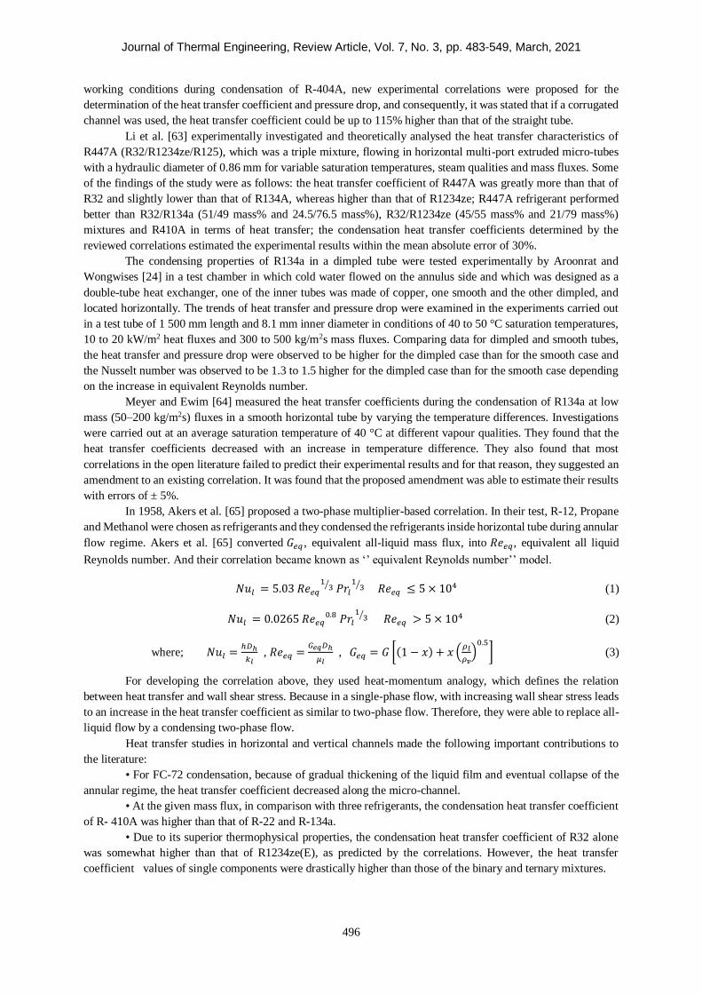
In 1958, Akers et al. [65] proposed a two-phase multiplier-based correlation. In their test, R-12, Propane
and Methanol were chosen as refrigerants and they condensed the refrigerants inside horizontal tube during annular
flow regime. Akers et al. [65] converted 𝐺𝑒𝑞 , equivalent all-liquid mass flux, into 𝑅𝑒𝑒𝑞, equivalent all liquid
Reynolds number. And their correlation became known as ‘’ equivalent Reynolds number’’ model.
𝑁𝑢𝑙 = 5.03 𝑅𝑒𝑒𝑞
13⁄ 𝑃𝑟𝑙
13⁄ 𝑅𝑒𝑒𝑞 ≤ 5 × 10⁴ (1)
𝑁𝑢𝑙 = 0.0265 𝑅𝑒𝑒𝑞0.8 𝑃𝑟𝑙
13⁄ 𝑅𝑒𝑒𝑞 > 5 × 10⁴ (2)
where; 𝑁𝑢𝑙 =ℎ𝐷ℎ
𝑘𝑙 , 𝑅𝑒𝑒𝑞 =
𝐺𝑒𝑞𝐷ℎ
𝜇𝑙 , 𝐺𝑒𝑞 = 𝐺 [(1 − 𝑥) + 𝑥 (
𝜌𝑙
𝜌𝑣)
0.5
] (3)
For developing the correlation above, they used heat-momentum analogy, which defines the relation
between heat transfer and wall shear stress. Because in a single-phase flow, with increasing wall shear stress leads
to an increase in the heat transfer coefficient as similar to two-phase flow. Therefore, they were able to replace all-
liquid flow by a condensing two-phase flow.
Heat transfer studies in horizontal and vertical channels made the following important contributions to
the literature:
• For FC-72 condensation, because of gradual thickening of the liquid film and eventual collapse of the
annular regime, the heat transfer coefficient decreased along the micro-channel.
• At the given mass flux, in comparison with three refrigerants, the condensation heat transfer coefficient
of R- 410A was higher than that of R-22 and R-134a.
• Due to its superior thermophysical properties, the condensation heat transfer coefficient of R32 alone
was somewhat higher than that of R1234ze(E), as predicted by the correlations. However, the heat transfer
coefficient values of single components were drastically higher than those of the binary and ternary mixtures.
Journal of Thermal Engineering, Review Article, Vol. 7, No. 3, pp. 483-549, March, 2021
497
Fluids with low global warming potential and fluids used in technological cooling have also been studied
recently. Technological developments and the widespread use of environmentally friendly practices demonstrate
that research in this direction will increasingly continue.
Smooth Tubes with Inclined Orientation
The inclination effect on condensation characteristics for smooth pipes was investigated in a sophisticated
two-part study by Lips and Meyer [37, 66]. They demonstrated the alteration of flow pattern, heat transfer
coefficient, void fraction and pressure drop for all the various inclination angles at experimental set-up. The
selected refrigerant R134a at a saturation temperature of 40 °C circulated inside a smooth pipe with an inner
diameter of 8 mm. Mass fluxes ranged from 200 to 600 kg/m2s and vapour qualities ranged from 0.1 to 0.9. They
observed that flow profile and condensation heat transfer were strongly influenced by inclination angle. In the
downward flows, 15° angle in the pipe increased the heat transfer coefficient up to 20%, whereas in the upward
flows, declines could be observed. The experimental data of Lips and Meyer [37, 66] were used to develop
correlations to predict heat transfer and pressure drop characteristics of flow [38]. The authors focused on the
stratified flow model and thus they investigated heat transfer characteristics, flow behaviour and pressure drop.
According to the experimental findings, the maximum heat transfer coefficient occurred at about an inclination
angle of 15°. It was shown that the capillary forces and gravitational forces were dominant in conditions of two-
phase stratified flow. New correlations for heat transfer and pressure drop calculations were developed and
compared with existing experimental literature. It was observed that the developed correlations were compatible
with the data in the literature and further experimental research was needed for better understanding of flow
characteristics in inclined pipes.
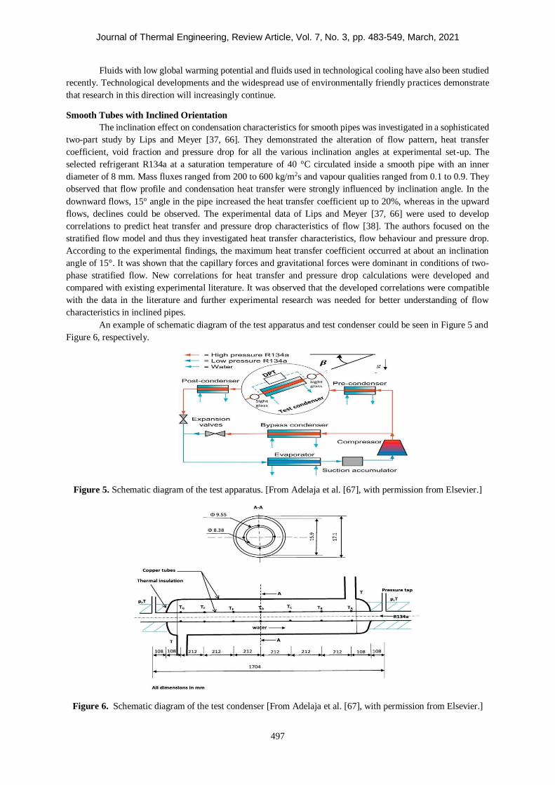
An example of schematic diagram of the test apparatus and test condenser could be seen in Figure 5 and
Figure 6, respectively.
Figure 5. Schematic diagram of the test apparatus. [From Adelaja et al. [67], with permission from Elsevier.]
Figure 6. Schematic diagram of the test condenser [From Adelaja et al. [67], with permission from Elsevier.]
Journal of Thermal Engineering, Review Article, Vol. 7, No. 3, pp. 483-549, March, 2021
498
An experimental investigation of convective condensation of R134a flow in an inclined smooth copper
pipe was conducted by Adelaja et al. [68]. Experiments were performed in the following conditions: 8.38 mm
inner diameter of pipe, 200 to 400 kg/m2s mass flux of flow, -90° to +90° inclination angle of pipe, 40 °C mean
saturation temperature of liquid and 0.1 to 0.9 vapour quality of fluid. According to the results, the vapour quality
and inclination angle had a strong influence on the heat transfer. The developed correlation by the authors yielded
the following: for horizontal flow, mean and average deviations of 9.22% and 3.44% respectively; for vertical
downward flow, 19.41% and 5.25% respectively. As in the previous studies [6, 8, 9] it was stated that the
inclination angle was more effective at low mass flux.
Mohseni et al. [69] performed an experiment on a testing apparatus which contained a plain pipe with
different inclination angles from -90° to +90°. Refrigerant R134a flowed in the system with mass fluxes ranging
from 53 to 212 kg/m2s for each inclination case. The research showed that pipe inclination substantially affected
vapour and condensed liquid distribution, and consequently, also the condensation heat transfer, especially at low
mass flux and vapour quality. The researchers reported that the optimum heat transfer coefficient occurred at an
inclination angle of +30° and the minimum heat transfer coefficient occurred at an inclination angle of -90°. The
developed correlation could predict the experimental data accurately within ±14 %.
Xing et al. [70] experimentally investigated condensation heat transfer during the flow of refrigerant
R245fa in a pipe with a length of 1 200 mm and a diameter of 14.81 mm. The refrigerant mass fluxes, vapour
qualities and the inclination angle of pipes varied from 191.3 to 705.4 kg/m2s, 0.191 to 0.947 and 90° to 90°
respectively. The major flow patterns in the condenser pipes were stratified-smooth, intermittent and stratified-
wavy flows. The best-performing heat transfer coefficient occurred at inclination angles of -15° and +30°. The
research indicated that the inclination angle had a strong effect on the heat transfer coefficient for the near-
horizontal position of the pipe. A new experimental correlation for condensation heat transfer was developed,
which was in good agreement with vapour mass quality and Froude number.
On the vertical and the inclined thermosyphons, both theoretical and experimental investigations were
conducted by Wang and Ma [71]. +15° to +90° inclination angle of pipe was arranged for the experimental set-
up in conditions that were 10 to 40 kW/m2 heat flux of condenser and 8 to 15 kPa of vapour pressure. The research
indicated an inclination angle effect on the condensation heat transfer coefficient and +20° to +50° of inclination
presented the optimum heat transfer. Finally, a semi-empirical correlation was presented. Wang and Du [72]
proposed an analytical model for predicting condensation heat transfer in inclined small/mini-diameter pipes. Four
different pipes were investigated in this research. It was shown that the effect of the inclination angle would
increase if the pipe diameter increased, but the effect of the inclination angle on Nusselt number was complex for
different sizes of pipes. Gravity had a decreasing effect on flow condensation, according to the results of this paper.
For a nearly horizontal pipe, Ahn et al. [39] developed a new model that included convective heat transfer
and film condensation. Heat transfer characteristics at inclination angles of 0° to +3° and diversified separated
flow regimes were investigated for air-water and steam-water conditions. The proposed method properly predicted
the characteristics of flow considering the experimental observations. Ahn et al. [40] also studied separated flow
regimes in the case of pure saturated steam flow in a 40 mm inner diameter pipe at inclination angles of -10° to
0°. Multidimensional parameters for local condensation heat transfer were selected as saturated steam at 1 to 5
bar of pressures and 10 to 50 kg/m2s of mass fluxes in an inclinable pipe with a length of 3 m. The proposed model
predicted the heat transfer coefficient according to the experimental data with an average deviation of 6.2%. The
authors anticipated that this model could be applicable to 35 to 40 mm of inner diameter pipes, 1 to 67 bar of
pressure and 10 to 329 kg/m2s of mass fluxes.
Steam condensation heat transfer characteristics in a 30° inclined pipe were experimentally studied by
Yang et al. [73]. The empirical correlation developed by the researchers predicted the condensation heat transfer
coefficient better for large-diameter inclined pipes than the correlations examined in the study. The researchers
concluded that heat transfer coefficients in inclined pipe were nearly 1.06 to 2.98 times better than for the
horizontal orientation.
A theoretical analysis was conducted by Hussein et al. [74] for laminar film condensation. An inclined
wickless heat pipe flat-plate solar collector was used for this purpose. It was concluded that condensation heat
transfer strongly influenced by the inclination angle and condenser section dimensions ratio. The authors pointed
out that the proposed equation for condensation heat transfer was valid for inclination angles of 0° to +90°.
One of the most comprehensive research works in the literature was carried out by Shah [75] as a result
of a detailed examination of the available experimental data from previous studies. The new correlation for heat
Journal of Thermal Engineering, Review Article, Vol. 7, No. 3, pp. 483-549, March, 2021
499
transfer was developed for conditions of pipe diameter of 2 to 49 mm, mass flux of 4 to 820 kg/m2s, Reynolds
number of 68 to 85 000, reduced pressure of 0.0008 to 0.9 and Prandtl number of 1 to 18. The experimental data
used for the validation of the developed correlation included 22 fluids (water, organics, hydrocarbon refrigerants,
halocarbon refrigerants) condensation in horizontal, vertical and downward-inclined pipes. The proposed
correlation showed good agreement with the vertical and horizontal orientations but not with the slightly inclined
orientation. Especially at Rev < 16 000, further investigations were needed for both horizontal and slightly inclined
cases. The author investigated condensation heat transfer in smooth conventional pipes as well as mini and micro-
pipes in another research paper [76]. Different types of pipe channels (rectangular, round, triangular, etc.), different
pipe orientations (-90° to +90°), different flowing fluids (33 fluids) and different experimental variables (0.1 to 49
mm diameter, 1.1 to 1400 kg/m2s mass flux, etc.) were analysed in detail and comprehensive correlations
predicting 4 063 data points with nearly 17% mean absolute deviations were developed.
Camaraza-Medina et al. [77] studied film condensation in pipes with various orientations observed from
available data in the literature. A new model was proposed and verified with 22 different flowing fluids for 2 to
50 mm inner diameter, 0.1 to 0.9 steam quality, 3 to 850 kg/m2s mass flux and other parameters mentioned in the
research paper. The developed model showed good agreement with all cases of pipe orientation and could be
considered proper for practical designs. Würfel et al. [41] investigated two-phase friction factor, heat transfer, film
thickness and also entrainment for n-heptane/air, condensing n-heptane and water/air fluid flow in an inclined
pipe. The authors proposed a special model for local condensation heat transfer in terms of the experimental
outcomes.
Ewim et al. [78] measured the heat transfer coefficients and flow patterns during the condensation of
R134a in a smooth inclined tube at low mass fluxes at a mean saturation temperature of 40 oC. They carried out
experiments for various mean vapour qualities between 0.1 to 0.9 in a test section with an inside diameter of 8.38
x 10-3 m and a length of 1.5 m. It was found that altering the inclination angles significantly altered the heat transfer
coefficients and flow patterns. For instance, the highest heat transfer coefficients were found at inclinations of
−15o and −30o and the corresponding lowest temperature difference was tested for in each case. In general, it was
observed that the heat transfer coefficients were more sensitive to downward flows than to upward flows. It was
also found that the heat transfer coefficients for downward and upward vertical orientations (+90o and -90o) were
not dependent on the temperature difference. It was also found that the inclination effect decreased with an
increase in temperature difference and increased with a decrease in mass flux and vapour quality.
Most recently, Adelaja et al. [67] proposed a model capable of predicting the heat transfer coefficients
during condensation inside inclined tubes subject to diabatic conditions. They used an extensive database of
experimental results collected from the research group led by Professor Josua Meyer to develop the model. It was
found that this new proposed model showed an excellent agreement with the experimental data within a global
average and mean absolute deviations of -5.74% and 1.13% respectively. The performance of the new model was
also compared with results from three different laboratories and the new model predicted them with a high level
of accuracy.
Heat transfer studies in smooth inclined channels made the following important contributions to the
literature:
• Heat transfer coefficients in inclined tubes were approximately 1.06 to 2.98 times higher than those in
horizontal tubes due to tilting influences of the heat transfer during condensation in a tube.
• The condenser section dimensions ratio had a significant effect on the condensation heat transfer
coefficient inside the inclined wickless heat pipes.
The work on smooth straight pipes has been more intensely studied due to the absence of structures such
as fins that disrupt the flow characteristics. However, straight pipes are less efficient than enhanced pipes
considering the limitations in the ability to improve the thermophysical properties of the flow and the
disadvantages such as taking up more space.
Enhanced Tubes with Inclined Orientation
Akhavan-Behabadi et al. [79] studied refrigerant R134a condensation in a micro-fin pipe with different
orientations of the inclination angle between the range of -90° and +90°. Three mass velocities were also tested
at 54, 81, and 107 kg/m2s. The heat transfer coefficient greatly increased with slightly inclined horizontal
orientations and the inclination of +30° generated the highest value of the experiments. However, the lower heat
transfer was observed for vertical orientations. Research revealed a 32 to 48% difference between the best
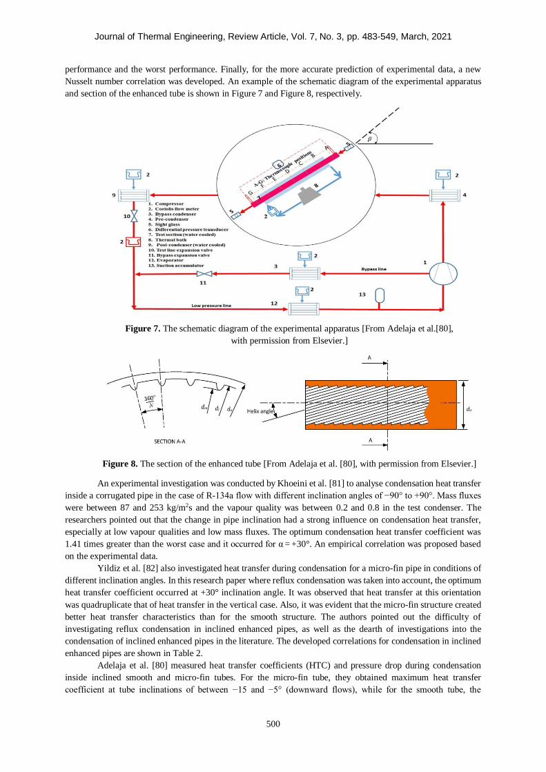
Journal of Thermal Engineering, Review Article, Vol. 7, No. 3, pp. 483-549, March, 2021
500
performance and the worst performance. Finally, for the more accurate prediction of experimental data, a new
Nusselt number correlation was developed. An example of the schematic diagram of the experimental apparatus
and section of the enhanced tube is shown in Figure 7 and Figure 8, respectively.
Figure 7. The schematic diagram of the experimental apparatus [From Adelaja et al.[80],
with permission from Elsevier.]
Figure 8. The section of the enhanced tube [From Adelaja et al. [80], with permission from Elsevier.]
An experimental investigation was conducted by Khoeini et al. [81] to analyse condensation heat transfer
inside a corrugated pipe in the case of R-134a flow with different inclination angles of −90° to +90°. Mass fluxes
were between 87 and 253 kg/m2s and the vapour quality was between 0.2 and 0.8 in the test condenser. The
researchers pointed out that the change in pipe inclination had a strong influence on condensation heat transfer,
especially at low vapour qualities and low mass fluxes. The optimum condensation heat transfer coefficient was
1.41 times greater than the worst case and it occurred for α = +30°. An empirical correlation was proposed based
on the experimental data.
Yildiz et al. [82] also investigated heat transfer during condensation for a micro-fin pipe in conditions of
different inclination angles. In this research paper where reflux condensation was taken into account, the optimum
heat transfer coefficient occurred at +30° inclination angle. It was observed that heat transfer at this orientation
was quadruplicate that of heat transfer in the vertical case. Also, it was evident that the micro-fin structure created
better heat transfer characteristics than for the smooth structure. The authors pointed out the difficulty of
investigating reflux condensation in inclined enhanced pipes, as well as the dearth of investigations into the
condensation of inclined enhanced pipes in the literature. The developed correlations for condensation in inclined
enhanced pipes are shown in Table 2.
Adelaja et al. [80] measured heat transfer coefficients (HTC) and pressure drop during condensation
inside inclined smooth and micro-fin tubes. For the micro-fin tube, they obtained maximum heat transfer
coefficient at tube inclinations of between −15 and −5° (downward flows), while for the smooth tube, the
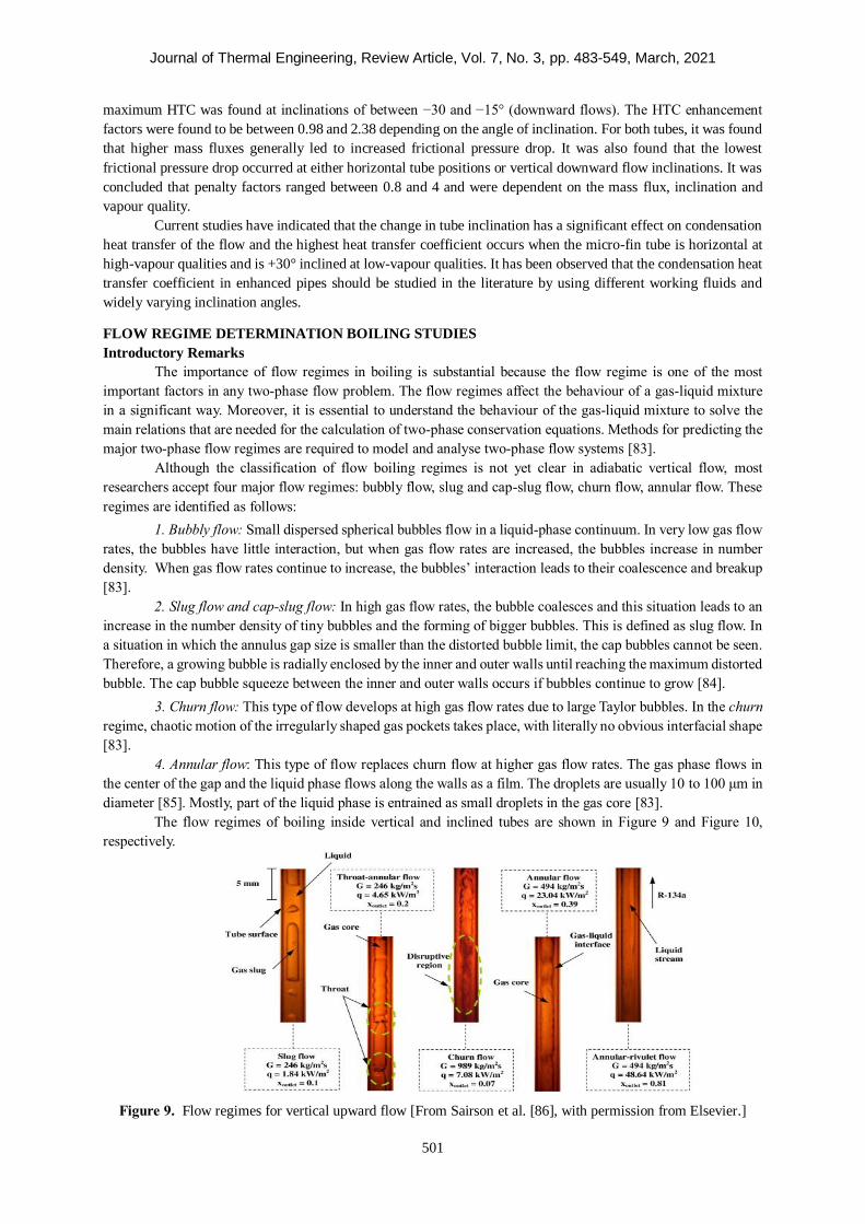
Journal of Thermal Engineering, Review Article, Vol. 7, No. 3, pp. 483-549, March, 2021
501
maximum HTC was found at inclinations of between −30 and −15° (downward flows). The HTC enhancement
factors were found to be between 0.98 and 2.38 depending on the angle of inclination. For both tubes, it was found
that higher mass fluxes generally led to increased frictional pressure drop. It was also found that the lowest
frictional pressure drop occurred at either horizontal tube positions or vertical downward flow inclinations. It was
concluded that penalty factors ranged between 0.8 and 4 and were dependent on the mass flux, inclination and
vapour quality.
Current studies have indicated that the change in tube inclination has a significant effect on condensation
heat transfer of the flow and the highest heat transfer coefficient occurs when the micro-fin tube is horizontal at
high-vapour qualities and is +30° inclined at low-vapour qualities. It has been observed that the condensation heat
transfer coefficient in enhanced pipes should be studied in the literature by using different working fluids and
widely varying inclination angles.
FLOW REGIME DETERMINATION BOILING STUDIES
Introductory Remarks
The importance of flow regimes in boiling is substantial because the flow regime is one of the most
important factors in any two-phase flow problem. The flow regimes affect the behaviour of a gas-liquid mixture
in a significant way. Moreover, it is essential to understand the behaviour of the gas-liquid mixture to solve the
main relations that are needed for the calculation of two-phase conservation equations. Methods for predicting the
major two-phase flow regimes are required to model and analyse two-phase flow systems [83].
Although the classification of flow boiling regimes is not yet clear in adiabatic vertical flow, most
researchers accept four major flow regimes: bubbly flow, slug and cap-slug flow, churn flow, annular flow. These
regimes are identified as follows:
1. Bubbly flow: Small dispersed spherical bubbles flow in a liquid-phase continuum. In very low gas flow
rates, the bubbles have little interaction, but when gas flow rates are increased, the bubbles increase in number
density. When gas flow rates continue to increase, the bubbles’ interaction leads to their coalescence and breakup
[83].
2. Slug flow and cap-slug flow: In high gas flow rates, the bubble coalesces and this situation leads to an
increase in the number density of tiny bubbles and the forming of bigger bubbles. This is defined as slug flow. In
a situation in which the annulus gap size is smaller than the distorted bubble limit, the cap bubbles cannot be seen.
Therefore, a growing bubble is radially enclosed by the inner and outer walls until reaching the maximum distorted
bubble. The cap bubble squeeze between the inner and outer walls occurs if bubbles continue to grow [84].
3. Churn flow: This type of flow develops at high gas flow rates due to large Taylor bubbles. In the churn
regime, chaotic motion of the irregularly shaped gas pockets takes place, with literally no obvious interfacial shape
[83].
4. Annular flow: This type of flow replaces churn flow at higher gas flow rates. The gas phase flows in
the center of the gap and the liquid phase flows along the walls as a film. The droplets are usually 10 to 100 μm in
diameter [85]. Mostly, part of the liquid phase is entrained as small droplets in the gas core [83].
The flow regimes of boiling inside vertical and inclined tubes are shown in Figure 9 and Figure 10,
respectively.
Figure 9. Flow regimes for vertical upward flow [From Sairson et al. [86], with permission from Elsevier.]
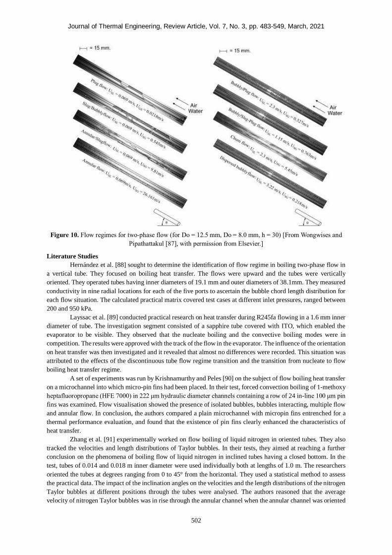
Journal of Thermal Engineering, Review Article, Vol. 7, No. 3, pp. 483-549, March, 2021
502
Figure 10. Flow regimes for two-phase flow (for Do = 12.5 mm, Do = 8.0 mm, h = 30) [From Wongwises and
Pipathattakul [87], with permission from Elsevier.]
Literature Studies
Hernández et al. [88] sought to determine the identification of flow regime in boiling two-phase flow in
a vertical tube. They focused on boiling heat transfer. The flows were upward and the tubes were vertically
oriented. They operated tubes having inner diameters of 19.1 mm and outer diameters of 38.1mm. They measured
conductivity in nine radial locations for each of the five ports to ascertain the bubble chord length distribution for
each flow situation. The calculated practical matrix covered test cases at different inlet pressures, ranged between
200 and 950 kPa.
Layssac et al. [89] conducted practical research on heat transfer during R245fa flowing in a 1.6 mm inner
diameter of tube. The investigation segment consisted of a sapphire tube covered with ITO, which enabled the
evaporator to be visible. They observed that the nucleate boiling and the convective boiling modes were in
competition. The results were approved with the track of the flow in the evaporator. The influence of the orientation
on heat transfer was then investigated and it revealed that almost no differences were recorded. This situation was
attributed to the effects of the discontinuous tube flow regime transition and the transition from nucleate to flow
boiling heat transfer regime.
A set of experiments was run by Krishnamurthy and Peles [90] on the subject of flow boiling heat transfer
on a microchannel into which micro-pin fins had been placed. In their test, forced convection boiling of 1-methoxy
heptafluoropropane (HFE 7000) in 222 μm hydraulic diameter channels containing a row of 24 in-line 100 μm pin
fins was examined. Flow visualisation showed the presence of isolated bubbles, bubbles interacting, multiple flow
and annular flow. In conclusion, the authors compared a plain microchannel with micropin fins entrenched for a
thermal performance evaluation, and found that the existence of pin fins clearly enhanced the characteristics of
heat transfer.
Zhang et al. [91] experimentally worked on flow boiling of liquid nitrogen in oriented tubes. They also
tracked the velocities and length distributions of Taylor bubbles. In their tests, they aimed at reaching a further
conclusion on the phenomena of boiling flow of liquid nitrogen in inclined tubes having a closed bottom. In the
test, tubes of 0.014 and 0.018 m inner diameter were used individually both at lengths of 1.0 m. The researchers
oriented the tubes at degrees ranging from 0 to 45° from the horizontal. They used a statistical method to assess
the practical data. The impact of the inclination angles on the velocities and the length distributions of the nitrogen
Taylor bubbles at different positions through the tubes were analysed. The authors reasoned that the average
velocity of nitrogen Taylor bubbles was in rise through the annular channel when the annular channel was oriented
Journal of Thermal Engineering, Review Article, Vol. 7, No. 3, pp. 483-549, March, 2021
503
at 0°, 10° and 20°. On the other hand, when the inclination angle was 30°, it was observed that the velocity grew
first, and then descended along the tubes; when the inclination angle was 45°, the velocity diminished along the
tubes. At the same x/D location, the velocity of the Taylor bubbles ascended first, and then fell with the increase
of θ.
Cornwell and Kew [92] intended to determine the flow regimes of R-113 flow boiling inside parallel
rectangular channels. A compact multi-channel plate was used. In the test, they used 75 channels with 1.2 mm
wide x 0.9 mm deep dimensions and 36 channels with 3.25 mm wide x 1.1 mm deep dimensions with vertical
orientation. Mass fluxes varied from 124 kg m2s⁄ to 627 kg m2s⁄ as the heat fluxes were between 3 and 33
kW m2⁄ . The mass fluxes and the mean heat fluxes were controlled and mean heat transfer coefficient was recorded
together with the flow regime by use of photographic and high-speed video techniques. They plotted a heat flux
and heat transfer coefficient graph showing the results for each zone and each geometry. Also, flow regimes were
observed. They observed that the flow was unstable at low flow rates. As a conclusion, they developed new Nusselt
number equations for each type of flow.
Kandlikar et al. [93] studied the flow boiling of water and observed the flow using a high-speed video
camera. In the test, multi-channel evaporators were made of six parallel channels on which heat flux was applied
electrically. They observed typical bubbly flow, annular flow and slug flow as well as nucleation. Moreover, to
understand the important fluctuations, visual confirmation of complete flow reversal in some of the channels was
made.
Lakshminarasimhan et al. [94] conducted practical research into flow boiling of R-11 in order to observe
the location at the beginning of nucleation. The channel used in the test was 20 mm wide x 357 mm long. The wall
of the channel was heated. The nucleation on the front was seen clearly in the laminar flow region. When the
turbulent region was seen on the front of the channel due to an increase in the flow rate, onset nucleate boiling
could not be determined clearly. However, onset nucleate boiling may have occurred at separate locations.
In conclusion, flow boiling inside horizontally, vertically or otherwise oriented tubes and channels was
investigated to determine flow regimes. The fluids which were examined for flow boiling were R245fa, R-11 and
R-113 liquid nitrogen HFE 7000. Hernández et al. [88] determined bubble chord length distribution for each flow
situations. Layssac et al. [89] researched the effects of discontinuous tube flow pattern transition and nucleation.
Krishnamurthy and Peles [90] observed isolated bubbles, bubbles interacting, multiple flow and annular flow.
Zhang et al. [91] found that the average velocity of nitrogen Taylor bubbles was in rise through the annular channel
when the annular channel was oriented at 0°, 10° and 20°. Cornwell and Kew [92] observed isolated bubbles,
confined bubbles and annular flow occurring at the same time. Kandlikar et al. [93] observed typical bubbly flow,
slug flow and annular flow as well as nucleation. Lakshminarasimhan et al. [94] aimed to observe the location of
the beginning of nucleation.
PRESSURE DROP DETERMINATION BOILING STUDIES
Introductory Remarks
As the pressure drop flow boiling is closely associated with the flow regimes, many researchers have been
interested in local pressure drop in well-analysed two-phase flow patterns. Therefore, the prediction of two-phase
pressure drop is a principal factor in designing a wide range of applications. The total pressure drop of fluid occurs
because of the variation of the kinetic and potential energies as well as the friction at the wall of the flow channel.
The total pressure drop can be calculated as:
∆𝑃𝑇𝑜𝑡𝑎𝑙 = ∆𝑃𝑠𝑡𝑎𝑡𝑖𝑐 + ∆𝑃𝑚𝑜𝑚𝑒𝑛𝑡𝑢𝑚 + ∆𝑃𝑓𝑟𝑖𝑐𝑡𝑖𝑜𝑛𝑎𝑙 (4)
The frictional pressure gradient is crucial for the total pressure drop. Two-phase frictional pressure drop is
dependent on mixture density, vapour quality and void fraction, velocity of vapour and liquid. It can be seen that
total pressure drop is the sum of acceleration, static and frictional pressure drop [95].
Horizontal and Vertical Orientations
Brutin and Tadrist [96] investigated the pressure drop of forced convection boiling in a mini-channel to
determine the effect of the inlet condition on two-phase flow stability. They used a rectangular mini-channel of
0.5 × 4 mm cross-section (hydraulic diameter: 889m). They investigated two-phase flow pressure drop at several
different mass fluxes for a specific heat flux. Steady and unsteady thermo-hydraulic performances were observed.
Journal of Thermal Engineering, Review Article, Vol. 7, No. 3, pp. 483-549, March, 2021
504
Steady and unsteady behaviours were calculated to be a function of the upstream boundary conditions. For the
steady state, a pressure loss model was suggested based on a homogeneous assumption.
Zhang et al. [97] did research on two-phase frictional pressure drop and void fraction in mini-channels.
They used the separated flow and drift-flux models in their research. They noted that the non-dimensional Laplace
constant was a principal parameter to correlate the Chisholm [98] parameter as well as the distribution parameter
in mini-channels. In conclusion, they stated that the Dukler [99] correlation, which is based on a homogeneous
model, conformed well with adiabatic two-phase flow as well as liquid-vapour flow, while prediction of the flow
boiling data was not good. The Mishima-Hibiki [100] correlation also showed best performance when the existing
void fraction correlations were reviewed extensively.
Celen et al. [101] researched the forced convection boiling heat transfer and pressure drop tryouts in order
to examine augmentation of the micro-fin tube for the heat transfer rate. They compared the results with those of
a plain tube. The practical boiling heat transfer coefficient and total pressure drop of R134a boiling inside the
micro-fin tube were measured to be 1.9 and 3.0 times higher than for the plain tube for the same fin root diameter
respectively. They also found that total pressure drop ascended with an increase in vapour quality, saturation
temperature and mass flux. The heat transfer coefficient increased up to 1.9 times owing to an increase in heat
transfer area, wetted perimeter and contribution of micro-fins to radial flows in the tube. The results also presented
a disadvantageous situation: higher roughness and micro-fins affected the friction factor considerably, hence it
was found that the pressure drop increased up to three times in the micro-fin tube.
Tong et al. [102] conducted practical research on pressure drop with highly subcooled forced convection
boiling in small-diameter tubes. They experimentally determined the parameters having an important effect on
pressure drop in highly subcooled flow boiling. These parameters were mass flux, internal diameter, aspect ratio,
inlet temperature and exit pressure. The tube in the test had inner diameters which ranged from 1.05 to 2.44 mm.
Other parameters were mass fluxes of 25000 to 45000 kg m2⁄ s, exit pressure was 4 to 16 bar and inlet temperatures
ranged from 22 to 66 ℃. They concluded that mass flux, tube inner diameter and aspect ratio were the parameters
which most affected the pressure drop. In two-phase flow, the pressure drop went up with an increase in mass flux
and with a decrease in aspect ratio. According to them, both inlet temperature and exit pressure affected two-phase
boiling significantly.
Müller-Steinhagen and Heck [103] investigated pressure drop of flow boiling in tubes and presented a
simple pressure drop correlation. Furthermore, they controlled the suggested correlation and 14 other correlations
in the literature, which measured 9 300 data points for frictional pressure drop for numerous fluids. They observed
that the best agreement between predicted and measured values was reached by using the correlation developed
by Bandel [104].
Yan et al. [105] conducted a test on the pressure drop of water flow boiling. The test situation was highly
subcooled and under high heat and mass fluxes. The tube oriented vertically and had a diameter of 9 mm and
length of 400 mm. Other parameters were 0 to 12.5 MW m2⁄ for heat fluxes, and 6000 to 10000 kg m2s⁄ for mass
fluxes, 3 to 5 MPa for pressure and 6 to 224 °∁ for liquid subcooling. According to their observations, the
subcooled boiling pressure drop went up when heat and mass fluxes increased. However, the pressure drop
decreased with increasing pressure. They concluded that there was a huge difference between correlations used
and the test results because of varying parameters and fluids.
Tran et al. [106] conducted tests experimentally on two-phase pressure drop of fluids flowing in small
channels and compared the results with correlations in the literature. By improving these correlations, they
suggested a new correlation. R-134a, R-12 and R-113 were used as refrigerants. The pressure drop ranged from
138 to 856 kPa and two different size tubes and one channel were used. One tube had a diameter of 2.46 mm and
the other tube had a diameter of 2.92 mm. The dimensions of the rectangular channel were 4.06 x 1.7 mm. They
used state-of-the-art correlations by employing the R-134a data. As a result, the new correlation was compared
with the experimental data for the three fluids and the deviation was found to be ± 20%.
Ribatski et al. [107] analysed the practical data for two-phase frictional pressure drop in micro-channels
and compared the prediction methods. They obtained the experimental data from the literature. The pressure drop
data covered both adiabatic and diabatic conditions with eight fluids. Mass fluxes ranged from 23 to 6000 kg m2s⁄ .
They analysed the data and compared the data with 12 two-phase frictional pressure drop prediction correlations.
They reported that Müller-Steinhagen and Heck [103] and Mishima and Hibiki [100] presented the best predictions
Journal of Thermal Engineering, Review Article, Vol. 7, No. 3, pp. 483-549, March, 2021
505
besides the homogeneous model. However, the data and correlations showed poor agreement at vapour qualities
higher than 0.5.
Steinke and Kandlikar [108] researched forced convection boiling and pressure drop in micro-channels
during laminar flow. An experimental test was conducted and the characteristics of both heat transfer and pressure
drop were analysed. Six parallel channels with diameter of 0. 207 mm in which water flowing inside were tested.
They found that the adiabatic friction factor calculated was in good agreement within the ± 10% error range.
Yun et al. [109] carried out tests on evaporative heat transfer and pressure drop of R410A in rectangular
micro-channels. The channels had hydraulic diameters of 1.36 and 1.44 mm. The saturation temperatures were 0,
5 and 10 ℃ as constant. The mass flux ranged from 200 to 400 kg m2s⁄ with 10 to 20 kW m2⁄ as heat flux. They
observed that the correlations in the literature predicted the two-phase pressure drop well. Moreover, the pressure
drop of R410A was similar to that in larger-diameter tubes.
The pressure drop of R-134a in a small annular-shaped channel oriented horizontally was researched by
Yan and Lin [110]. The pipe was circular and had a diameter of 2.0 mm. They investigated pressure drop
characteristics in order to design effective evaporators for cooling systems. They reported that the pressure drop
calculated was higher with an increase in the mass rates and heat flux. According to the data obtained, they
presented empirical correlations for the friction factors of the evaporation.
Mancin et al. [111] conducted practical research on R134a flowing inside a micro-fin tube, which had a
diameter of 3.4 mm. The inside part of the tube was coated with copper and heated electrically. The test was
conducted at constant saturation temperature of 30 ℃ . The mass fluxes were between 190 kg m2s⁄ and 940
kg m2s⁄ and heat fluxes were 10, 25 and 50 kW m2⁄ with the vapour quality between 0.2 and 0.99. They measured
the total pressure drop at 25 kW m2⁄ heat flux. At constant mass velocity, they observed that the two-phase
frictional pressure drop increased with increasing vapour quality until a certain value of vapour quality. After some
point, the two-phase flow friction factor decreased with an increase in vapour quality. Regarding the constant
vapour quality, the pressure drop increased with an increase in mass velocity.
Park and Hrnjak [112] experimentally researched the forced convection boiling heat transfer and pressure
drop of CO2, R410A and R22. The test was conducted at adiabatic conditions and constant wall temperature and
at low temperatures in horizontal plain tube, which had a diameter of 6.1 mm. Other parameters were -15 and -30
℃ evaporation temperatures and 100 to 400 kg m2s⁄ mass flux and heat flux of 5 to 15 kW m2⁄ ; the vapour quality
ranged from 0.1 to 0.8. They calculated various mass fluxes, evaporation temperatures and qualities. According to
their calculations, the Müller-Steinhagen and Heck [103] and Friedel [113] correlations predicted the best within
the ± 30% error range.
Kuo and Wang [114] experimentally studied forced convection boiling of R22 and R407C. A microfin
tube having nominal diameter of 9.52 mm was used. The researchers investigated two-phase heat transfer
coefficient characteristics as well as pressure drop. The test was conducted under the condition of evaporation
pressure of 600 kPa. It was found that the pressure drop of R407C was 30 to 50% lower than for R22. They
implemented another approach to lessen the two-phase friction data. They produced new parameters: two-phase
friction factor ftp consisting of a mean two-phase viscosity, ��. They also expressed two-phase friction factors
consisting of two-phase friction factor ftp. as shown in Table 15.
Rollmann and Spindler [115] presented new models for boiling heat transfer of R407C and R410A inside
horizontal microfin tubes. They also researched pressure drop characteristics. The experiments were carried out at
saturation temperatures between –30 and + 10 ℃ and heat fluxes between 1 000 and 20 000 W/m2. The mass flux
ranged from 25 to 300 kg/m2s and vapour quality was between 0.1 and 1.0. They yielded a correlation for the total
pressure drop as shown in Table 15. The mean deviation of the measured values from the experimental ones was
18.1%.
Didi et al. [116] researched the prediction of the boiling pressure drop of refrigerants in horizontal tubes.
They aimed to compare the prediction methods in the literature. The authors used the data obtained from Kattan
[117], who did tests under the conditions of mass flux between 100 and 500 kg/m2s and vapour quality between
0.04 and 1.0. The refrigerants of the research were R-134a, R-123, R-402A, R- 404A and R-502 flowing inside
two horizontal tubes having diameters of 10.92 and 12.00 mm. The prediction methods of Lockhart and Martinelli
[118], Friedel [113], Grönnerud [119], Chisholm [120], Bankoff [121], Chawla [122] and Müller-Steinhagen and
Heck [103] were compared. They reported that Müller-Steinhagen and Heck [103] and Grönnerud’s [119] methods
were the best method for predicting annular flow. Friedel 114’s method came third in prediction accuracy.
Journal of Thermal Engineering, Review Article, Vol. 7, No. 3, pp. 483-549, March, 2021
506
In this section, pressure drop of horizontally and vertically oriented tubes as presented in the literature
were investigated. Experimental tests were conducted at different mass flow rates, heat fluxes and vapour qualities.
The findings were compared with the outcomes of correlations based on the homogeneous model and found to be
in good agreement. In the studies, the errors ranged from ±10% to ±30 %.
Smooth Tubes with Inclined Orientation
Maddi and Rao [123] conducted practical tests on forced convection boiling in tubes inclined in solar
collectors. They tested 700 sets of heat transfer coefficients and 900 sets of pressure drop in inclined flow boiling.
They reported that the heat transfer and frictional pressure drop in flow boiling were influenced by the angle of
inclination in the bubbly and discontinuous flow regimes, while the inclination was marginally affected in the tube
flow regime.
Wang et al. [124] investigated the effect of inclination on the flow boiling efficiency of a microchannel
heat sink. In the research, HFE-7100 was used as fluid. The heat sink consisted of a multi-port microchannel
having a hydraulic diameter of 0.825 mm. The microchannel heat sink was oriented from - 90° to + 90°. They
found that the heat transfer coefficient of the channel oriented vertically was similar to that of the channel oriented
horizontally. Comparing the channel oriented 45° upwards with the other channel inclinations, it was found that
the 45° inclination angle had the highest heat transfer rate.
Jang et al. [125] investigated flow boiling pressure drop of FC-72 in small channel heat sinks. The heat
sinks, which were used for cooling of electronic devices, had an inner diameter of 2 mm and outer diameter of 4
mm with 100 mm length. The heat flux was applied to the copper block with the magnitude of 0.5 to 3.0 W cm2⁄ .
They modified the current pressure drop correlations according to data obtained. The homogeneous pressure drop
model predicted the pressure drop at 0.9% for average and 27.0% for mean deviations, while the average and mean
deviations of the original homogeneous model were -41% and 49.8% respectively.
Wongwises and Pipathattakul [87] researched pressure drop of two-phase flow in an inclined channel.
The two-phase flow was gas-liquid flow in a narrow annular channel. The research was done experimentally. The
round-shaped channel in the test section had an inner diameter of 8 mm and outer diameter of 12.5 mm. In this
test, flow patterns were also observed through a high-speed camera. They observed slug flow regime in the
horizontal channel. At low liquid velocity in the horizontal channel, the presence of slug flow slowed down the
pressure drop for a short time, then raised the pressure drop after the air velocity increased. According to their
observation, with channel orientations at 30° and 60°, the pressure did not increase suddenly with slug-bubbly
flow.
Tshuva et al. [126] conducted a practical test on two-phase flow in inclined parallel tubes. Two-phase
flow in parallel tubes was used in the direct steam generation by solar heating. In the test, two pipes were placed
parallel and the third one was for control. The pipes had a diameter of 24 mm and length of 300 cm. The pipes
were oriented from 0° to 90°. They used physical models to calculate the pressure model. Firstly, they determined
the flow pattern then the pressure drop was obtained by physical models. They concluded that the symmetric
distribution of the two phases yielded less pressure drop than that of all the other combinations of gas and liquid.
In this part of the literature review, the presented degree of tube inclinations ranged from - 90° to + 90°.
Maddi and Rao [123] found that in bubbly and discontinuous flow regimes, the inclination affected the flow regime
in an important manner. Wang et al. [124] observed that the results were best at 45° inclination angle. Jang et al.
[125] compared their results with the homogeneous model. According to them, the homogeneous model predicted
the pressure drop with average and mean deviations of 0.9% and 27.0%. Wongwises and Pipathattakul [87] found
that slug flow slowed down the pressure drop for a short time, then raised the pressure drop after the air velocity
increased. Tshuva et al. [126] concluded that the symmetric distribution of the two phases yielded less pressure
drop.
Enhanced Tubes with Inclined Orientation
An example of the schematic diagram of test apparatus and sketch and real photo of the enhanced tube
could be seen in Figure 11 and Figure 12, respectively.
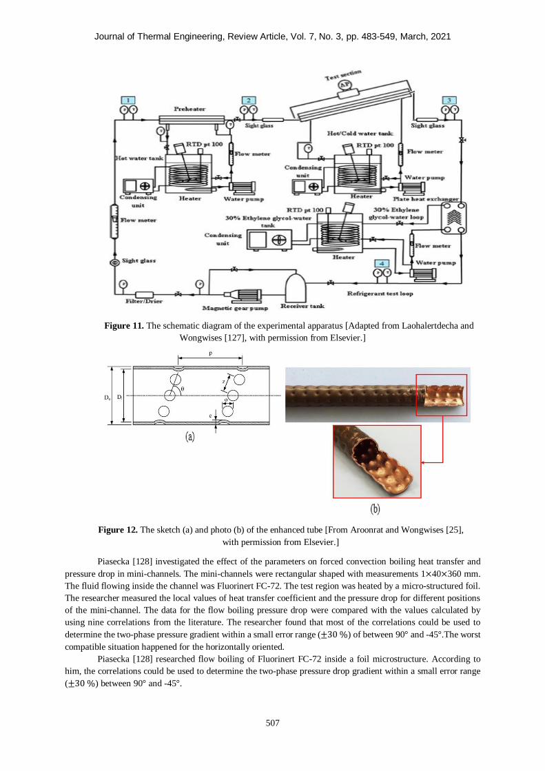
Journal of Thermal Engineering, Review Article, Vol. 7, No. 3, pp. 483-549, March, 2021
507
Figure 11. The schematic diagram of the experimental apparatus [Adapted from Laohalertdecha and
Wongwises [127], with permission from Elsevier.]
Figure 12. The sketch (a) and photo (b) of the enhanced tube [From Aroonrat and Wongwises [25],
with permission from Elsevier.]
Piasecka [128] investigated the effect of the parameters on forced convection boiling heat transfer and
pressure drop in mini-channels. The mini-channels were rectangular shaped with measurements 1×40×360 mm.
The fluid flowing inside the channel was Fluorinert FC-72. The test region was heated by a micro-structured foil.
The researcher measured the local values of heat transfer coefficient and the pressure drop for different positions
of the mini-channel. The data for the flow boiling pressure drop were compared with the values calculated by
using nine correlations from the literature. The researcher found that most of the correlations could be used to
determine the two-phase pressure gradient within a small error range (±30 %) of between 90° and -45°.The worst
compatible situation happened for the horizontally oriented.
Piasecka [128] researched flow boiling of Fluorinert FC-72 inside a foil microstructure. According to
him, the correlations could be used to determine the two-phase pressure drop gradient within a small error range
(±30 %) between 90° and -45°.
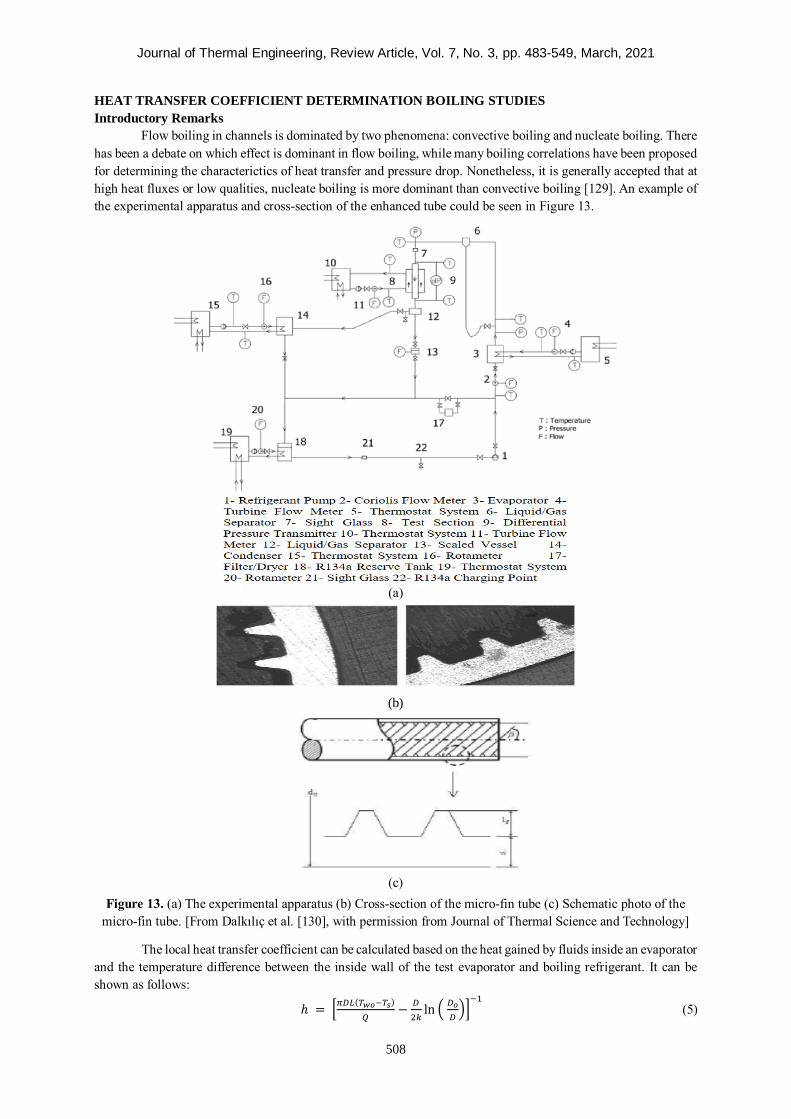
Journal of Thermal Engineering, Review Article, Vol. 7, No. 3, pp. 483-549, March, 2021
508
HEAT TRANSFER COEFFICIENT DETERMINATION BOILING STUDIES
Introductory Remarks
Flow boiling in channels is dominated by two phenomena: convective boiling and nucleate boiling. There
has been a debate on which effect is dominant in flow boiling, while many boiling correlations have been proposed
for determining the characterictics of heat transfer and pressure drop. Nonetheless, it is generally accepted that at
high heat fluxes or low qualities, nucleate boiling is more dominant than convective boiling [129]. An example of
the experimental apparatus and cross-section of the enhanced tube could be seen in Figure 13.
(a)
(b)
(c)
Figure 13. (a) The experimental apparatus (b) Cross-section of the micro-fin tube (c) Schematic photo of the
micro-fin tube. [From Dalkılıç et al. [130], with permission from Journal of Thermal Science and Technology]
The local heat transfer coefficient can be calculated based on the heat gained by fluids inside an evaporator
and the temperature difference between the inside wall of the test evaporator and boiling refrigerant. It can be
shown as follows:
ℎ = [𝜋𝐷𝐿(𝑇𝑤𝑜−𝑇𝑠)
𝑄−
𝐷
2𝑘ln (
𝐷𝑜
𝐷)]
−1
(5)
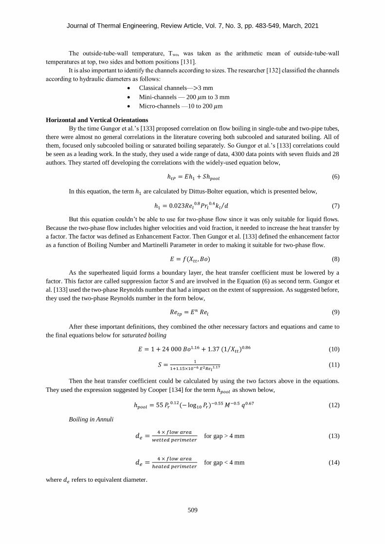
Journal of Thermal Engineering, Review Article, Vol. 7, No. 3, pp. 483-549, March, 2021
509
The outside-tube-wall temperature, Two, was taken as the arithmetic mean of outside-tube-wall
temperatures at top, two sides and bottom positions [131].
It is also important to identify the channels according to sizes. The researcher [132] classified the channels
according to hydraulic diameters as follows:
Classical channels—>3 mm
Mini-channels — 200 𝜇m to 3 mm
Micro-channels —10 to 200 𝜇m
Horizontal and Vertical Orientations
By the time Gungor et al.’s [133] proposed correlation on flow boiling in single-tube and two-pipe tubes,
there were almost no general correlations in the literature covering both subcooled and saturated boiling. All of
them, focused only subcooled boiling or saturated boiling separately. So Gungor et al.’s [133] correlations could
be seen as a leading work. In the study, they used a wide range of data, 4300 data points with seven fluids and 28
authors. They started off developing the correlations with the widely-used equation below,
ℎ𝑡𝑃 = 𝐸ℎ1 + 𝑆ℎ𝑝𝑜𝑜𝑙 (6)
In this equation, the term ℎ1 are calculated by Dittus-Bolter equation, which is presented below,
ℎ1 = 0.023𝑅𝑒𝑙0.8𝑃𝑟𝑙
0.4𝑘𝑙 𝑑⁄ (7)
But this equation couldn’t be able to use for two-phase flow since it was only suitable for liquid flows.
Because the two-phase flow includes higher velocities and void fraction, it needed to increase the heat transfer by
a factor. The factor was defined as Enhancement Factor. Then Gungor et al. [133] defined the enhancement factor
as a function of Boiling Number and Martinelli Parameter in order to making it suitable for two-phase flow.
𝐸 = 𝑓(𝑋𝑡𝑡 , 𝐵𝑜) (8)
As the superheated liquid forms a boundary layer, the heat transfer coefficient must be lowered by a
factor. This factor are called suppression factor S and are involved in the Equation (6) as second term. Gungor et
al. [133] used the two-phase Reynolds number that had a impact on the extent of suppression. As suggested before,
they used the two-phase Reynolds number in the form below,
𝑅𝑒𝑡𝑝 = 𝐸𝑛 𝑅𝑒𝑙 (9)
After these important definitions, they combined the other necessary factors and equations and came to
the final equations below for saturated boiling
𝐸 = 1 + 24 000 𝐵𝑜1.16 + 1.37 (1 𝑋𝑡𝑡⁄ )0.86 (10)
𝑆 =1
1+1.15×10⁻⁶ 𝐸2𝑅𝑒𝑙1.17 (11)
Then the heat transfer coefficient could be calculated by using the two factors above in the equations.
They used the expression suggested by Cooper [134] for the term ℎ𝑝𝑜𝑜𝑙 as shown below,
ℎ𝑝𝑜𝑜𝑙 = 55 𝑃𝑟0.12(− log10 𝑃𝑟)−0.55 𝑀−0.5 𝑞0.67 (12)
Boiling in Annuli
𝑑𝑒 =4 × 𝑓𝑙𝑜𝑤 𝑎𝑟𝑒𝑎
𝑤𝑒𝑡𝑡𝑒𝑑 𝑝𝑒𝑟𝑖𝑚𝑒𝑡𝑒𝑟 for gap > 4 mm (13)
𝑑𝑒 =4 × 𝑓𝑙𝑜𝑤 𝑎𝑟𝑒𝑎
ℎ𝑒𝑎𝑡𝑒𝑑 𝑝𝑒𝑟𝑖𝑚𝑒𝑡𝑒𝑟 for gap < 4 mm (14)
where 𝑑𝑒 refers to equivalent diameter.
Journal of Thermal Engineering, Review Article, Vol. 7, No. 3, pp. 483-549, March, 2021
510
Subcooled Boiling
They used the equation below instead of the Equation (6) because there were differences at temperatures
of nucleate boiling and forced boiling. Also, there was almost no vapor, the enhancement factor should have been
removed.
𝑞 = ℎ1(𝑇𝑤 − 𝑇𝑏) + 𝑆ℎ𝑝𝑜𝑜𝑙(𝑇𝑤 − 𝑇𝑠) (15)
After comparing the measured heat two-phase heat transfer coefficients with calculated ones by using
their suggested new equations, they concluded that they found the mean deviations were 21.4% for saturated
boiling and 25.0 % for subcooled boiling.
Özdemir [135] researched single-phase flow and forced convection boiling of water in metallic micro-
channels. He scrutinised the characteristics of the single-phase flow and flow boiling heat transfer. Four oxygen-
free copper test sections were operated throughout the experiments. Three microchannel test sections, which had
the same length (L = 62 mm) and hydraulic diameter (Dh = 0.561 mm) but different aspect ratios (β = 0.5, 2.56
and 4.94), were investigated to determine the influence of channel aspect ratio on single-phase flow and flow
boiling. Furthermore, a longer test section (Dh = 0.561 mm, L = 86.8 mm and β = 2.56) was examined in order to
display the effect of channel heated length. The influences of heat flux were evident on boiling curves, while the
effect of the mass rates on the boiling curves was insignificant. The heat transfer coefficient increased with
increasing heat flux and was not dependent on the local vapour quality at low and medium heat fluxes. However,
the heat flux had no impact on the heat transfer coefficient at high heat fluxes. The heat transfer coefficient
diminished when the mass flux increased owing to the high pressure drop.
Lazarek and Black [136] conducted tests on the evaporative heat transfer of a small vertical tube carrying
R-113. Also, pressure drop and critical heat flux were reviewed. In the tests, an annular channel was employed.
The tube had an internal diameter of 0.031 mm. The experiments consisted of vertical, co-current upflow and
downflow configurations. The authors presented an equation for the local heat transfer coefficient and the Nusselt
number consisting of liquid Reynolds number and boiling number. According to the researchers, the subcooled
and saturated boiling sections of the boiling curve were very reproducible throughout the tests. Initial nucleation,
for example, took place at different combinations of increasing heat flux for the inlet and discharge tubes.
Li and Wu [137] experimentally investigated the characteristics of saturated flow boiling heat transfer for
both multi- and single-channels in micro- and mini-channels. The authors employed 3 700 data points, including
numerous working fluids, operational conditions and different diameters of microchannel. The complete record
was assessed by means of various extant correlations to prove their relevant accuracies. However, no extant
correlation could define the data set exactly. A general correlation consisting of Reynolds number, boiling number
and Bond number was given for boiling heat transfer in micro- and mini-channels.
Ong and Thome [2] conducted experimental research on flow boiling of R134a, R236fa and R245fa in a
horizontally oriented 1.030 mm tube in order to find true flow boiling heat transfer outcomes. The researchers
analysed the boiling phenomena for mass fluxes varying between 200 and 1 600 kg/m2s, heat fluxes between 2.3
kW/m2 and 250 kW/m2 at Tsat = 31 °C and ∆Tsub from 2 to 9 K. They deduced that the heat transfer coefficients
of R134a and R236fa increased with the rise in heat flux for numerous qualities at low mass fluxes. Furthermore,
they observed that the fluid characteristics significantly affected the heat transfer characteristics of the fluid.
Candan et al. [138] experimentally investigated flow boiling heat transfer in mini-channels. In their
measurements, they employed five single-channel heat sinks which had the same hydraulic diameter but with
different width and depth. In order to perceive the boiling mechanism meticulously, flow visualisation tests were
conducted. Also, temperature and pressure measurements were taken. They acquired the influences of different
values of the mass flux, vapour quality, heat flux and aspect ratio (ratio of width to depth) on heat transfer
coefficient and pressure drop. They also gained the optimum value of the aspect ratio for a broad range of working
parameters. It was found that two-phase flow local heat transfer coefficient did not ascend or descend
monotonically according to the aspect ratio. On the whole, the best performance for heat transfer was enabled
when AR was equal to 1 with the worst performance when the aspect ratio equaled 0.25. The heat transfer
coefficient increased with increment in heat flux, mass flux and vapour quality. The authors compared their study
with that of Markal et al. [139] and found that in contrast with the Markal et al. [139] study, in their own study,
nucleate boiling was dominant because the heat transfer mechanism and flow patterns in micro-channels were
clearly different. They noted that the cause of the differences was the effects of restrictions. They also concluded
Journal of Thermal Engineering, Review Article, Vol. 7, No. 3, pp. 483-549, March, 2021
511
that the heat transfer coefficient increased with an increase in the heat flux, mass flux, and the local vapor quality.
The total pressure drop increased with increasing heat flux, mass flux and vapour quality.
Markal et al. [140] conducted tests on flow boiling in micro-channels. They measured pressure,
temperature, flow rate and heat fluxes and detailed flow visualisation using a high-speed camera. They did the
tests under different geometrical dimensions, various mass and heat fluxes. They investigated the influences of
mass flux, vapour quality, aspect ratio (ratio of width to length), hydraulic diameter and heat flux on the two-phase
heat transfer coefficient and total pressure drop. The authors ascertained the heat transfer coefficients by applying
obtained values and existing correlations. They also derived a novel correlation. They found that flow boiling in
micro-channels had unique characteristics according to the experimental study and flow visualisation, and hence
the characteristics of micro-channels differed from those of macro-channels. Moreover, when flow patterns were
visualised, the authors noted that the main flow patterns were extended bubble flow and annular flow, adding that
the dominant heat transfer mechanism was convective boiling and aspect ratio and hydraulic diameter parameters
impacted flow and heat transfer characteristics
Nedaei [141] researched subcooled flow boiling in enhanced micro-channels. The researcher also made
modifications on surface characteristics. The test consisted of two parts. In the first part, the researcher covered
the inner wall of the stainless steel micro-tubes with polyhydroxyethylmethacrylate
(pHEMA)/polyperfluorodecylacrylate (pPFDA) by means of applying an initiated chemical vapour deposition
(iCVD) method in order to examine the wettability along the surface. The outcomes of the work were contrasted
with those of a bare tube surface. In conclusion, pertaining to the first part of the study, the researcher found
subcooled boiling heat transfer to be remarkably increasing with covering, as the highest heat transfer coefficient
to arise when the pHEMA was coated with a 64% increase in heat transfer. In the second part of the study, a
horizontal aluminum microchannel having a length of 14 cm, width of 1.5cm and depth of 500μ was taken into
account. Subcooled boiling heat transfer was reviewed. The tests were run for the different fluxes of 70, 100 and
125 kWm-2. The researcher concluded that plates sanded with grit sizes of 400 and 1 000 improved heat transfer
coefficient.
Kandlikar [142] presented a general correlation for two-phase flow boiling heat transfer in vertical and
horizontal annular channels. The author suggested a simple correlation to find saturated flow boiling heat transfer
coefficients for horizontal and vertical tubes. It was in accordance with a model benefitting the contributions owing
to nucleate boiling and convective mechanism. The correlation given accounted for both these cases.
Passos et al. [143] implemented convective boiling measurements of R- 407c. In their tests, refrigerant
R- 407c flowed inside horizontal tubes. The tests were realised for two types of tubes, microfin having an outside
diameter of 12.7 mm and smooth tubes having outside diameters of 7 mm. Practical outcomes on the nucleate and
flow boiling of R-407c were gained. The data were obtained for heat fluxes at 10 and 20 kWm-2. The results
obtained are summarised as follows: for tubes having outside diameter of 7 mm, the heat transfer coefficient for
the micro-fin tubes was found to be greater (100%) than that of the smooth ones and the enhancement was larger
than the rise in the heat transfer surface area of the microfin tubes with a surface factor of 1.46.
Dalkılıç et al. [144] conducted practical research on the flow boiling of R134 in a microchannel heat sink.
They employed rectangular micro-channels as heat sinks. The channel in the test was made of copper and had a
width of 0.382 mm and a depth of 0.407 mm as well as a fin thickness of 0.416 mm. Total of 27 parallel rectangular
micro-channels in heat sinks were operated. In these measurements, the inlet saturation temperatures of fluid were
constant at 18 C, 23 C and 28 C. The mass fluxes were altered from 800 𝑘g⁄𝑚2𝑠 to 1200 𝑘g⁄𝑚2𝑠. In each test,
they launched the heat flux at the wall as 50 𝑘W ⁄𝑚2 and increased it to reach the critical heat flux. Throughout
the tests, the vapour quality at the entrance of the micro-channels was kept constant. They concluded that at low
vapour quality, the heat transfer coefficient notably went up with increment in heat flux. Moreover, the mass flux
was seen to have almost no effect. The authors added that with an increase in heat flux, convective boiling
increased more than nucleate boiling. After this transition, the heat transfer coefficient was found to increase with
the rise in vapour quality and mass flux until dryout point. It was observed that the heat transfer coefficient
ascended with increase in saturation temperatures for all conditions.
Ozdemir et al. [145] conducted a practical study of single-phase and boiling flow in micro-channels. The
researchers did their work at high flow rates. They divided the test into two parts. In the first part, fluid flow was
examined within a wide range of mass velocities with different inner diameters in micro-channels. They employed
deionised water as working fluid. The wall temperatures and pressure drop were measured. As a result, the heat
transfer coefficient was acquired. Afterwards, they calculated Nusselt numbers and friction factors by executing
Journal of Thermal Engineering, Review Article, Vol. 7, No. 3, pp. 483-549, March, 2021
512
the obtained parameters. The results were consistent with the existing theory, which was for flows in microscale
and under both laminar and turbulent behaviour. In the second part of their study, boiling heat transfer
characteristics were examined in the identical microchannel conditions. For this part, they deduced that high heat
removal could be enabled at high flow rates for subcooled boiling situations. In addition to this, they determined
that heat transfer coefficients increased with rising mass velocities while falling with heat flux. They concluded
their study by comparing the experimental outcomes with extant partial boiling correlations in the relevant
literature, and fully developed flow correlations.
Wambsganss et al. [146] presented the results of their research on boiling heat transfer of R-113 in a
horizontal small-diameter tube of 2.92 mm diameter. Local heat transfer coefficients were calculated for a range
of heat flux (8.8 - 90.75 kW m2⁄ ). Mass flux varied between 50 and 300 kg m2⁄ s and equilibrium mass quality
was between 0 and 0.9. They developed 10 different heat transfer correlations by using the experimental results of
local heat transfer coefficients. The researchers observed that small channels showed a slug flow pattern for a
variety of parameters compared with higher-diameter channels. Having occurred high boiling number and slug
flow pattern brought about a domination by nucleation mechanism. They observed that the two-phase correlations
agreed well when the physical parameters were modelled properly. They concluded that the results were strong
functions of heat flux and only slightly dependent on mass rates. They reported that the values they calculated in
their study complied with the measured values of Reid et al. [147] at relatively high boiling numbers and dominant
flow of nucleation in large regions.
The findings by Tran et al. [148] in determining the dependency of the heat transfer coefficient in boiling
were surprising. They noted that the heat transfer coefficients were influenced by heat flux only. These results
were uncommon. The mass flux had reportedly no effect on the heat transfer coefficient. These findings were
supported by Kasza et al. [149], who researched the flow boiling of water in rectangular channels with 2.5 mm x
6 mm dimensions. They found that high heat transfer coefficient in mini- channels occurred thanks to an increase
in bubble activity in thin liquid film
Shiferaw et al. [150] conducted experimental research on flow boiling of R134a. R134a flowed in a tube
of 1.1 mm internal diameter. They also presented a three-zone flow model. In the test, the mass flow rate was
between 100 and 600 kg m2⁄ s and pressure was between 6 and 12 bar and heat flux was 16 and 150 kW m2⁄ . For
low heat and mass flux when the quality was below 50%, the heat transfer coefficient was dependent on heat flux
and pressure because it was independent of the vapour quality and the effect of mass flux was negligible. They
noted that the three-zone evaporation agreed fairly well with the experimental results. Though the dryout region
was observed at high quality, it was quite higher than the model predicted.
Ravigururajan et al. [151] tested the flow boiling of R-124 in micro-channels which had 0.27 mm x 11
mm cross-section. They observed that an increase in quality led to a decrease in heat transfer coefficient, which
fell from 11 kW m2⁄ ℃ at x = 0.01 to 8 kW m2⁄ ℃ at x = 0.65. These results indicated that the higher vapour
fraction caused flow oscillations in multi-channels and increased the heat transfer coefficient.
In and Jeong [1] have made experimental investigation in order to search characteristics of flow boiling
inside micro tubes having 1.9 mm inner diameter. R123 and R134a were used as fluid in their tests. Heat fluxes
and mass velocities were 10, 15, 20 kW/m2 and 314, 392, 470 kg/m2s respectively while vapor qualities ranged
from 0.2 to 0.85 and different saturation pressures (158, 208 kPa for R123; 900, 1100 kPa for R134a). They found
that the suppression of nucleate boiling at low vapor quality determines the heat transfer tendency and mechanism
in the flow boiling of micro channels.
The reviewed heat transfer determination studies were summarised in this section. Flow boiling of R-124,
R134a, R-113, R134, R- 407c, R236fa, R245fa and water inside horizontal and vertical tubes was investigated in
the condition of subcooled and saturated flow boiling. The studies were conducted at different mass fluxes, heat
flux rates and qualities. Shiferaw et al. [150] found that the heat transfer coefficient was dependent on heat flux
and pressure, while it was independent of the vapour quality. Tran et al. [148] noted that heat transfer coefficients
were affected by heat flux only. Wambsganss et al. [146] concluded that the results were strong functions of heat
flux and only weakly dependent on mass rates. Özdemir [145] deduced that high heat removal could be enabled
at high flow rates for subcooled boiling situations. Dalkılıç et al. [144] found that the heat transfer coefficient
notably went up with increment in heat flux at low vapour quality. Passos et al. [143] found that for tubes having
an outside diameter of 7 mm, the heat transfer coefficient for the micro-fin tubes was calculated as greater (100
%) than for the plain tubes.
Journal of Thermal Engineering, Review Article, Vol. 7, No. 3, pp. 483-549, March, 2021
513
Smooth Tubes with Inclined Orientation
Kundu et al. [152] investigated the influences of mass fluxes, heat fluxes and tube inclination angles on
the boiling heat transfer coefficient. In their experimental test, refrigerant R407C was boiling flowing through a
plain tube with 7.0 mm hydraulic diameter at different tube inclinations. They proposed new correlations. The
tests involved five different tube inclination angles which varied from 0° to 90° of the direction of the refrigerant
flow. The test indicated that the heat transfer coefficient increased with an increase in mass velocity and heat flux.
The angle of tube inclination had a substantial influence on the flow boiling heat transfer coefficient of R407C.
The highest heat transfer coefficient of 90° was achieved in the route of fluid flow for all mass velocities. It was
found that the error range of the proposed new correlations was ± 20 % and – 3.68 % of MPE, an MAE of 10.44
% and an RMSE of 12.68 %.
Kundu et al. [153] conducted a practical test to determine the characteristics of flow boiling heat transfer
of R134a and R407C in a plain tube at different inclinations. They conducted a practical analysis of using R134a
and R407C in a smooth copper tube. Tubes had inclination angles ranging between 0° and 90° for five different
angles. The practical data were attained for a mass velocity ranging from 100 to 300 kg/m2 s, heat flux range of 3
to 10 kW/m2 with inlet temperature of 5 to 9 °C and vapour quality ranging from 0.1 to 0.9. The tube length tested
was 1.2 m, the plain tube which was made of copper had an inner diameter of 7.0 mm and outside diameter of 9.52
mm.
Gang et al. [154] researched forced convection heat transfer characteristics of inclined tubes. Tests were
carried out to study the flow boiling heat transfer of water in an inclined upward tube oriented at 20°. The other
conditions were that the tube had an inner diameter of 26 mm. They found that the dissipation of heat transfer
characteristics through the circumference of the inclined tube was non-uniform. The wall temperature was in
decrease, and therefore, the heat transfer coefficient increased with an increase in circumferential angle.
Morcos et al. [155] experimentally examined boiling heat transfer in rectangular channels. The channels
were oriented horizontally as well as inclined. They conducted the test under a relatively low heat flux. The test
facility included aluminum rectangular channels, which were electrically heated and had aspect ratios of 2.67 and
0.37. The practical consequences of the two-phase Nusselt number for the two aspect ratios and for the inclination
angles of 0, 15, 30 and 45 degrees were correlated with a ratio of the two-phase to the liquid-phase Reynolds
number for the forced convection vaporisation region. The test outcomes revealed that NuTP for a given aspect
ratio and inclination angle depended not only on ReTP but also on the mass velocity G. For the given values of
ReTP and G, increasing the aspect ratio led to an increase in NuTP. Furthermore, the optimal value of the inclination
angle which yielded the maximum value of NuTP was calculated the same at 30°. In the flow boiling region, the
practical consequences of NuTP for horizontal and inclined channels were very well correlated using a ratio of ReTP
to Rel. They found that the correlations fairly complied with the practical data of previous investigations.
Wang et al. [156] conducted practical research into the characteristics of heat transfer of water flowing
inside an inclined downward tube. Tests were run through a supercritical pressure CFB boiler. The tube in the test
was oriented at 45° from the horizon with an inner diameter of 20 mm. The tests were conducted in the following
conditions: heat flux from 50 to 585 kW/m2, pressure from 11.5 to 28 MPa, mass flux from 450 to 1550 kg/m2 s.
It was shown that the heat transfer characteristics of water in the inclined downward tube were not uniform along
the circumference from the top surface to the bottom surface. When the heat flux increased, non-uniformity
increased. When pressures were diminished under subcritical conditions, both dryout and departure from nucleate
boiling (DNB) occurred at the top surface of the tube. Conversely, dryout was only observed on the bottom surface
of the tube and in the vertical downward tube.
Jeong and Kim [157] investigated the subcooled boiling impact of an inclined downward-facing surface.
In the work, the channel was settled to be 10° upwards from the horizon. The researchers employed a copper block
as a test heater, which was placed above the flow channel to simulate the passive cooling system of an ex-vessel
core catcher designed for nuclear power plants. Low mass flux and subcooled boiling conditions ranged between
40 and 300 kg/m2 s and 5 to 25 K respectively. A slight dependence of critical heat flux on the subcooling was
seen with the conditions up to subcooling of 15 K.
This section reviewed research on oriented smooth tubes and channels to determine heat transfer rates.
Kundu et al. [152] found the highest heat transfer rate at 90° in the route of fluid flow for all mass velocities. Gang
et al. [154] noted that the heat transfer coefficient increased with increasing circumferential angle. Morcos et al.
[155] concluded that the correlations were in fair compliance with the practical data of previous investigators.
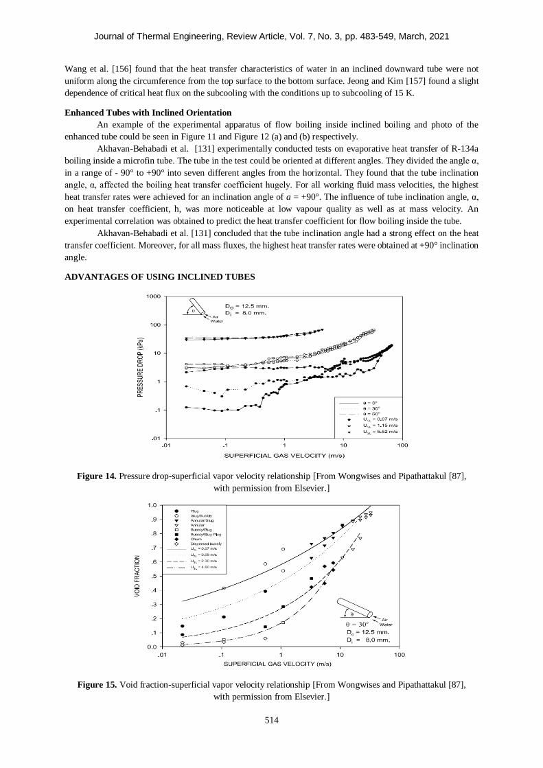
Journal of Thermal Engineering, Review Article, Vol. 7, No. 3, pp. 483-549, March, 2021
514
Wang et al. [156] found that the heat transfer characteristics of water in an inclined downward tube were not
uniform along the circumference from the top surface to the bottom surface. Jeong and Kim [157] found a slight
dependence of critical heat flux on the subcooling with the conditions up to subcooling of 15 K.
Enhanced Tubes with Inclined Orientation
An example of the experimental apparatus of flow boiling inside inclined boiling and photo of the
enhanced tube could be seen in Figure 11 and Figure 12 (a) and (b) respectively.
Akhavan-Behabadi et al. [131] experimentally conducted tests on evaporative heat transfer of R-134a
boiling inside a microfin tube. The tube in the test could be oriented at different angles. They divided the angle α,
in a range of - 90° to +90° into seven different angles from the horizontal. They found that the tube inclination
angle, α, affected the boiling heat transfer coefficient hugely. For all working fluid mass velocities, the highest
heat transfer rates were achieved for an inclination angle of a = +90°. The influence of tube inclination angle, α,
on heat transfer coefficient, h, was more noticeable at low vapour quality as well as at mass velocity. An
experimental correlation was obtained to predict the heat transfer coefficient for flow boiling inside the tube.
Akhavan-Behabadi et al. [131] concluded that the tube inclination angle had a strong effect on the heat
transfer coefficient. Moreover, for all mass fluxes, the highest heat transfer rates were obtained at +90° inclination
angle.
ADVANTAGES OF USING INCLINED TUBES
Figure 14. Pressure drop-superficial vapor velocity relationship [From Wongwises and Pipathattakul [87],
with permission from Elsevier.]
Figure 15. Void fraction-superficial vapor velocity relationship [From Wongwises and Pipathattakul [87],
with permission from Elsevier.]
Journal of Thermal Engineering, Review Article, Vol. 7, No. 3, pp. 483-549, March, 2021
515
In two-phase flow, phenomena that affect the performance of the system in the first order, such as heat
transfer and pressure drop, occur in a complex way depending on liquid-vapor distribution, steam quality, mass
flux, channel geometry and channel inclination. For instance, at high velocities, as the increase in the flow velocity
will increase the heat transfer due to the turbulence effects and at the same time increase the pressure drop, both
phenomena should be taken into account in order to determine the system performance. Besides these main
phenomena, void fraction also affects system performance. In a sample curved pipe model to be considered, the
gravity effect will be more dominant compared to the horizontal position with respect to the direction of flow
(upflow or downflow). The flow that slows down or accelerates with this effect will adopt different flow regimes
depending on the internal structure of the geometry. The balance of gravity and inertial forces will affect the liquid-
vapor distribution. As the angle of inclination increases, liquid splashes will develop and flow characteristics will
change significantly. Vapor bubbles in liquid or liquid droplets in vapor will exhibit more unstable movements
than horizontal orientation. All of this shows why it took many years to develop correlations for wide flow
velocities and wide databases of fluid flow types. However, research in the literature has shown that the use of
inclined channels in a two-phase flow with well-defined boundary conditions can significantly improve system
performance. It is a much easier solution to incline the channel to increase performance rather than to create
different geometry structures or to have additional power-consuming systems at these well-defined intervals. In
addition, as the studies progress, when inclined flows are provided in enhanced channels, much more compact and
less space-consuming, high-performance systems can be developed.
As seen in the Figure 14, the pressure drop depends on the flow regime and the velocity of the vapor
and liquid. As the gas velocity increases until sufficiently turbulent flows, the pressure drop increases. The inclined
channel structure slows down the turbulent flow occurrence with the effect of gravity. High vapor and liquid
velocities reduce the gravitational effect on the flow, resulting in pressure drop similar to the horizontal orientation.
This system shows that it is highly possible to create structures where inclined pipes would be advantageous for a
system in which heat transfer coefficient improvement can be achieved. In Figure 15 it is seen that the increase in
vapor velocity also increases the void fraction. In addition, it can be said that the system performance can improved
with the void fraction decreasing and the gas-liquid transitivity changing in different flow regimes when the
inclination increases. The part to be noted here is the determination of the best performance inclinations for flows
by conducting preliminary research and narrowing the inclination angles to be studied.
RESULTS AND DISCUSSION
In this literature review, condensation and boiling heat transfer characteristics in horizontal, vertical and
inclined tubes were scrutinized. Nearly all research subjects were summarised as presented in the literature, such
as boiling heat transfer studies according to inclined tubes and tube geometry (plain and enhanced tubes). In the
last section of this paper, the tables summarizes the literature studies of condensation and boiling in inclined pipes
in order to present in a single publication current correlations for inclined pipes, information from recent
experimental studies as well as recommendations for improvements for future studies.
In the light of studies in the literature, the objectives of this research were to extend our understanding of
flow condensation and flow boiling heat transfer characteristics in inclined tubes and channels, evaluate the effects
of roughness, heat flux, vapor quality, inclination angle, mass flux, saturation temperature, aspect ratio and other
parameters on condensation and boiling, evaluate the performance of correlations in prediction of two-phase heat
transfer, present the researchers’ new correlations and compare them with their own empirical results. The effects
of parameters on both condensation and boiling heat transfer coefficient inside tubes are summarised below.
Effects of Parameters on Condensation Heat Transfer Characteristics
Effects of the main parameters on the heat transfer coefficient
Roughness:
Channels with enhanced surfaces where the effect of roughness is important has been extensively studied
on horizontal and vertical pipes, and there are very limited studies on inclined pipes.
In the vapor condensation study of pure R134a in a helically inclined (18°) microfin tube studied by Arslan and
Eskin [60], the fins performed turbulence increasing properties for all experiments.
Yarmohammadi & Farhadi [62] investigated straight and corrugated tubes for R-404A condensation and
they conclude heat transfer coefficient in corrugated channels could be up to 115% higher than that of the straight
tube.
Journal of Thermal Engineering, Review Article, Vol. 7, No. 3, pp. 483-549, March, 2021
516
Yildiz et al. [82] take into account reflux condensation in their research and microfin pipe experiments
showed optimum heat transfer coefficient occurred at +30° inclination angle and microfin structure created better
heat transfer characteristics according to the smooth structure.
For R134a, in microfin tube condensation maximum heat transfer coefficient occurred at tube inclinations
of between −15° and −5° (downward flows) whereas in smooth tube condensation maximum heat transfer
coefficient occurred at tube inclinations of between −30° and −15° (downward flows).
Vapor quality:
Steam condensation study [40] in horizontal and inclined tubes demonstrated that measured heat transfer
coefficient increases with increasing steam quality or increasing mass flux and decreasing pressure.
Jung et al. [52] performed experimental study on different types of pure refrigerants (R12, R22, R32,
R123, R125, R134a and R142b) and they found the heat transfer for R142b and R32 was higher than for R22,
whereas the heat transfer for R12 and R125 was lower than for R22; on the other hand, the heat transfer for R123
and R134a was similar for the same mass flux, also the condensation heat transfer increased with increasing mass
flux and increasing quality.
The research [59] on R1234yf refrigerant which has low global warming potential vapour quality
properties had strong effects on heat transfer and it was determined that the heat transfer coefficient increased with
the increase of vapor quality.
Mohseni et al. [69] investigated R134a condensation and they concluded pipe inclination substantially
affected vapour and condensed liquid distribution, and consequently, also the condensation heat transfer,
especially at low mass flux and vapour quality.
Ewim et al. [78] deduced the inclination effect decreased with an increase in temperature difference and
increased with a decrease in mass flux and vapour quality for R134a condensation in a smooth inclined tube.
Inclination Angle:
An experimental investigation [68] of convective condensation of R134a was stated that heat transfer
coefficient increases with increasing inclination angle for α<0°, inclination angle affects the heat transfer
coefficient differently with various mass flows for α>0°.
R245fa condensation study [70] presented that the inclination angle had a strong effect on the heat transfer
coefficient for the near-horizontal position of the pipe and the best-performing heat transfer coefficient occurred
at inclination angles of -15° and +30°.
Steam condensation in a 30° inclined pipe experimentally studied by Yang et al. [73] and research
propounded that heat transfer coefficients in inclined pipe were nearly 1.06 to 2.98 times better than for the
horizontal orientation.
A theoretical analysis [74] for laminar film condensation concluded that condensation heat transfer
strongly influenced by the inclination angle and condenser section dimensions ratio.
Adelaja et al. [83] concluded heat transfer coefficient enhancement factors were found to be between 0.98
and 2.38 depending on the angle of inclination.
Mass flux:
Lips and Meyer [38] concluded that the increase of the mass flux causes the increase in the heat transfer
due to the increase of the convective effect for higher mass fluxes.
Condensation heat transfer increases with increasing mass flux and decreasing condensation saturation
temperature according to Yang and Jia [57].
Heat transfer characteristics for R410A and R22 refrigerants flowing in a herringbone-type microfin tube
[61] were demonstrated that in the region where high mass flux was available, higher heat transfer provided in the
herringbone-type tube than for the helical microfin case, whereas heat transfer showed the opposite character for
the low mass flux region.
Condensation study of R134a in a smooth inclined tube at low mass fluxes at a mean saturation
temperature of 40 °C [78] showed that the inclination effect decreased with a decrease in mass flux and vapour
quality.
An experimental investigation of R-134a flow with different inclination angles of −90° to +90° inside a
corrugated tube [81] pointed out that the change in pipe inclination had a strong influence on condensation heat
transfer, especially at low vapour qualities and low mass fluxes.
Journal of Thermal Engineering, Review Article, Vol. 7, No. 3, pp. 483-549, March, 2021
517
Saturation temperature:
Condensate Nusselt number was found to be independent of the temperature difference in conditions
where the temperature difference (difference with saturation temperature and wall temperature) was higher than
2.58 °C in study of Arslan and Eskin [60].
Evim et al. [78] pointed out the heat transfer coefficients for downward and upward vertical orientations
(+90° and -90°) were not dependent on the temperature difference. It was also found that the inclination effect
decreased with an increase in temperature difference.
Other parameters:
Condensation heat transfer model package development study by Ahn et al. [39] presented that ratio of
Nusselt number increases with vapour Reynolds number (for film condensation heat transfer).
The research on the heat transfer characteristic of steam condensation [73] concluded heat transfer
coefficient increases with increasing Reynolds number and decreases with increasing tube axial distance.
Effects of the main parameters on the pressure drop-friction factor
Roughness:
Channels with enhanced surfaces where the effect of roughness is important has been extensively studied
on horizontal and vertical pipes, and there are very limited studies on inclined pipes.
Experimentally investigation on the pressure drop characteristics of two-phase forced flow for the pure R134 [27]
revealed the pressure drop was 10 to 50% higher than for the smooth condition in the micro-fin case.
For a counter flow concentric double-tube heat exchanger model R134a condensation in smooth and
corrugated tubes investigated [34] and researchers presented corrugation pitches had a considerable effect on the
pressure drop increment.
The research on R-600a condensation [50] revealed the pressure drop and the mean heat transfer
coefficient increased according to the straight condenser between the range of 33 and 157% and 24 and 165%
respectively.
Numerical research of hydrocarbon mixture upflow condensation characteristics in smooth and spirally
enhanced pipes [51] demonstrated that the increments of the pressure drop for spiral grooved, square corrugated
and sinusoidal corrugated were 0.851 to 3.587, 1.805 to 10.930 and 1.272 to 7.176 times higher than for the smooth
case.
Vapor quality:
Experimental investigation of condensation of R134a [27] presented the increase in pressure drop was
observed for increased vapour quality for both smooth and micro-fin structures.
For propane condensing in horizontal pipes [29] the pressure drop increased with increasing mass flow and vapour
quality, while the rising temperature decreased for the tube diameter.
R152a condensation study [33] in a 1.152 mm diameter circular channel and of 0.952 mm hydraulic
diameter rectangular channel demonstrated the pressure drop increased with increasing vapour quality. Pressure
drop study at low mass fluxes for R134a [49] showed that pressure drops increased with an increase in vapour
quality.
R-600a condensation in a helically inclined counter flow heat exchanger studied by Mozafari et al. [50]
and results demonstrated that higher condensation frictional pressure drop occurred when the vapor quality
increases.
Mass flux:
Pressure drop properties in a horizontal smooth tube for R32, R134a, R125, R236ea and R410A
condensation was carried out by Cavallini et al. [26] and they concluded that while the pressure drop showed high
values with high mass fluxes and vapour qualities, it showed low values for high saturation temperatures.
FC-72 condensation in parallel micro-channels [31] the pressure drop increased with increasing mass flux
of condensing FC-72 whereas the pressure drop decreased due to the flow deceleration caused by increasing the
mass velocity of cooling water [31]
Findings of condensation study of R152a [33] indicated that the pressure drop increased with increasing
vapour quality and mass flux, whereas the pressure drop decreased with increasing saturation temperature and
channel geometry almost not important for low mass fluxes.
Journal of Thermal Engineering, Review Article, Vol. 7, No. 3, pp. 483-549, March, 2021
518
Pressure drop characteristics investigated for low mass fluxes R134a condensation [49] and it was found
that the measured pressure drops increased with an increase in mass flux, temperature difference and vapour
quality.
In experimentally study of R134a flow [21] flow visualisation results showed the flow regime which
determine heat transfer characteristics was exceedingly influenced by the mass flux.
Inclination Angle:
Experimental findings in large flattened-tube steam condensers [14] showed that the increased inclination
angle led to a decrease in pressure drop due to gravity-assisted drainage of the condensate.
The research on R245fa condensation in phase separation shell-and-tube condenser [16] pointed out when
inclination angles varied from −30° to 30°, the pressure difference decreased but the liquid-mesh contact area
increased.
During the convective condensation of the R134a refrigerant, the increasing inclination and decreasing
vapour qualities increased the pressure drop for the inclined orientation [37]
Condensation heat transfer of R245fa studied by Xing et al. [70] and attained general trend is that the
pressure drop increases with increasing inclination angle, except for partial decreases.
A two-phase gas–liquid flow investigation [87] presented the inclination angle has significant effect on
pressure drop and void fraction. Increasing inclination leads to more turbulent flow and more prominent friction
effect.
Saturation temperature:
Experimental investigation for R32, R134a, R125, R236ea and R410A was carried out by Cavallini et al.
[26] and they concluded the pressure showed low values for high saturation temperatures.
The pressure drop decreased with increasing saturation temperature and channel geometry almost not
important low mass fluxes according to R152a condensation study [33]
Other parameters:
For horizontal and inclined upward air–water two-phase flow in a mini-gap annular channel, pressure
drop increases with increasing superficial gas velocity and void fraction increases with increasing superficial gas
velocity [87]
The study on the convective condensation of R134a presented the void fraction decreases with increasing
inclination angle [38]
Effects of Parameters on Boiling Heat Transfer Characteristics
Effects of the main parameters on the heat transfer coefficient
Roughness:
The studies reviewed have showed that the roughness had huge effect on flow boiling heat transfer
coefficient. Celen et al. [101] found that enhanced tube (micro-fin tube) had 1.9 times higher heat transfer
coefficient compared to plain one having same fin root diameter. The findings by Passos et al.[143] were similar
with similar geometry, 9.52 mm and 7.0 mm outside diameter of the micro-fin tube for Celen [101] and Passos’
studies [143] respectively. Passos et al. [143] have calculated that heat transfer coefficient of micro-fin tubes were
100 % higher compared to smooth one and this was higher than surface factor found as 1.46 for micro-fin tube.
The main reason why the heat transfer coefficient increases more than the surface factor is that micro-fin tubes
contribute to their radial flow.
Heat flux:
Almost all researches in our study, it was expected that, found that heat flux has influenced the boiling
heat transfer coefficient over wide range of amount. However, Tran et al. [148] stated that at wall superheats <
2,75C, the heat transfer coefficient was independent of heat flux, just dependent on the mass flux contrary to
Özdemir’s [135] findings that the heat transfer coefficient was only dependent on heat flux rather than mass flux.
This difference occurred due to the fact that Tran et al. defined their results within a very low wall superheats. To
express special case, Özdemir [135] found that the heat flux had no impact on heat transfer coefficient at high heat
fluxes.
Journal of Thermal Engineering, Review Article, Vol. 7, No. 3, pp. 483-549, March, 2021
519
Vapor quality:
Trend was generally that with increasing vapour quality resulted in increase in heat transfer coefficient.
Findings by researcher Candan et al. [138], Celen et al.[101], Krishnamurthy & Peles [90], Kundu et al. [153],
Ravigururajan et al. [151] were in comply with this. But there were some exceptions: Özdemir [135] and Markal
et al. [139] found the correlation in contrast with them, presenting no heat transfer increment with increasing heat
flux. And some researchers found that increasement in boiling heat transfer coefficient with increasing vapour
quality occurred until certain vapour quality, Jang et al. [125] and Akhavan-Behabadi et al. [131] obtained these
vapour qualities as 0,25 and 0,70-0,85 respectively.
Inclination Angle:
There were limited researchers who examined effect of inclination angle on heat transfer coefficient.
Simply there were two groups: researchers who observed that inclination angle considerably has affected heat
transfer coefficient and researcher in other group who did no see any enhancement in heat transfer coefficient.
While Maddi and Rao [123] just stated that inclination angle had influence on heat transfer coefficient marginally
without presenting at which inclination angles obtained best results, other researchers defined the best angle of
inclination that had highest heat transfer coefficient. Although Akhavan-Behabadi et al. [131] and Kundu et al.
[152] achieved the highest heat transfer rate at inclination angle of 90° (upflow), Wang et al. [124] obtained the
highest rate at 45°, and Morcos et al. [155] had the best results at 30° incliantion angle. Moreover, none of the
researchers had highest performance for downflow.
Mass flux:
The findings regarding the relation between heat transfer coefficient and mass flux was same, with the
exception of Dalkılıç et al. [144]’s findings,: the heat transfer coefficient increased with increasing mass flux.
Candan et al. [138] and Morcos et al. [155] have reached these results with channels while Akhavan-Behabadi et
al.[131], Özdemir [145], Kundu et al. [152], and Kundu et al. [153] have obtained these results with tubes. And
this situation shows us whether it is a channel or tube do not change the tendency that increasing mass flux results
in increasing heat transfer coefficient.
Dalkılıç et al. [144] found that mass flux did not affect the transfer coefficient at low vapour quality. However,
Dalkılıç et al. have increased the heat flux and found that the heat transfer has increased with increasing mass flux
until dryout point. In addition to the statements above, the trend was independent of fluid types. The authors have
gained these results with different types of fluids. R407C, R134a, and water was used for different studies.
Saturation temperature:
Celen et al. [101], Dalkılıç et al. [144], observed that the heat transfer coefficient has increased at all
saturation temperatures. This situation was expected. Because the saturation temperatures were relatively low.
Park and Hrnjak [112] compared the two saturation temperatures, and found that the two-phase flow heat transfer
coefficient at -15 °C saturation temperature was always higher than that of -30°C saturation temperature. They
explained this situation by stating that the nucleate boiling heat transfer was reduced with decrease in saturation
temperature.
On the other hand, Jang et al. [125] managed the test within a wide range of temperatures. Jang found
that the heat transfer coefficient has increased until 65 °C but decreased beyond 65 °C for saturation temperatures.
However, there was researcher who stated that trend of the heat transfer coefficient was dependent on the
experimental conditions. In and Jeong [1] indicated that the change in the heat transfer coefficient by saturation
pressure (saturation temperature) was insignificant at the high mass velocity and small at the low mass velocity.
Aspect Ratio:
Although some researchers indicated a profound relation between aspect ratio and heat transfer coefficient
for all conditions, there were other researchers who found this relation dependent on operating conditions.
Researcher Candan et al. [138] and Özdemir [135] stated that aspect ratio affected the heat transfer coefficient
highly in some conditions. Candan et al. [138] expressed that two-phase flow local heat transfer coefficient did
not ascend or descend monotonically according to the aspect ratio but showed best performance when AR was
equal to 1 with the worst performance when the aspect ratio equaled 0.25.
On the other hand, Özdemir [135] have seen high effect on local heat transfer coefficient of channel
aspect ratio at the low/medium heat flux and up to vapor quality of 0.2. But he did not see important effect at the
Journal of Thermal Engineering, Review Article, Vol. 7, No. 3, pp. 483-549, March, 2021
520
conditions of high heat flux. However, researcher Morcos et al. [155] found that Nusselt Number NuTP have
increased with increasing aspect ratio and Markal et al. [140] stated aspect ratio affected heat transfer
characteristics.
Other parameters:
There were other parameters other than aspect ratio, mass flux, heat flux, inclination angle, saturation
temperature, vapor quality and roughness. These were effect of covering, Wall temperature and Reynold Number.
Nedaei [141] found that when the tube was covered with pHEMA, the heat transfer coefficient has raised by 64%
compared to the bare tube. Gang et al. [154] found that the dissipation of heat transfer characteristics through the
circumference of the tube was uniform and with decreasing wall temperature, the heat transfer coefficient increased
with increasing circumferential angle. On the other hand, Morcos et al. [155] in addition to finding that NuTP for a
given aspect ratio and inclination angle depended on ReTP, They also stated that the practical consequences of NuTP
for horizontal and inclined channels were very well correlated using a ratio of ReTP to Rel. They found that the
correlations fairly complied with the practical data of previous investigations.
Performance of existing correlations in prediction of boiling heat transfer
There were some authors who compared the experimental results obtained with the proposed correlations in
the literature. Park and Hrnjak [112] for various mass fluxes, evaporation temperatures and qualities. They found
that the Müller-Steinhagen and Heck [103] and Friedel [113] correlations predicted the best within the ± 30%
error range. This result could be commented that the correlations were in comply with the experimental results.
Similarly, Ozdemir et al. [145] found that the results were consistent with the existing theory, which was for flows
in microscale and under both laminar and turbulent behavior.
However, Li and Wu [137] in their study including evaluation of 3 700 data points indicated that no extant
correlation could define the data set exactly. But these results covered just saturated boiling not subcooled flow
boiling. At the end of their study, they proposed a general correlation consisting of Reynolds number, boiling
number and Bond number was given for boiling heat transfer in micro- and mini-channels.
Effects of the main parameters on the pressure drop-friction factor
Flow Regime:
Effect of flow regimes were investigated by Wongwises and Pipathattakul [87] and Tshuva et al. [126].
According to Wongwises and Pipathattakul [87], they have seen slug flow regime and the presence of slug flow
slowed down the pressure drop for a short time, then raised the pressure drop after the air velocity increased at low
liquid velocity in the horizontal channel. However, they found that the channel oriented at 30° and 60°, the
pressure did not increase suddenly with slug-bubbly flow. On the other hand, in their practical research Tshuva et
al. [126] found that the symmetric distribution of the two phases yielded less pressure drop than that of all the
other combinations of gas and liquid.
Roughness:
Celen et al. [101] investigated the forced convection boiling heat transfer and pressure drop tryouts in
order to examine augmentation of the micro-fin tube for the heat transfer rate. They compared the results with
those of a plain tube. They found that total pressure drop of R134a boiling inside the micro-fin tube were calculated
to be 3.0 times higher than for the plain tube. Moreover, they stated that that total pressure drop ascended with an
increase in vapour quality, saturation temperature and mass flux.
Mass flux:
Researchers investigated effect of mass flux on pressure drop within wide range. While Tong et al. [102]
studied with high mass fluxes, from 25000 to 45000 kg m2⁄ s, Mancin et al. [111] conducted their research within
low mass flux, 190 kg m2s⁄ and 940 kg m2s⁄ . As expected, most researcher found that pressure drop have
increased with increasing mass flux. This trend was seen in boiling inside both enhanced tubes and plain tubes. As
Mancin et al. [111], Celen et al. [101] had this trend with micro-fin tubes, Tong et al. [102] Yan et al. [105] Yan
and Lin [110] had with plain ones.
Inclination Angle:
Maddi and Rao [123] investigated their tests on forced convection boiling in tubes inclined in solar
collectors. They stated that frictional pressure drop in flow boiling were influenced by the angle of inclination in
the bubbly and discontinuous flow regimes, while the inclination was marginally affected in the tube flow regime.
Journal of Thermal Engineering, Review Article, Vol. 7, No. 3, pp. 483-549, March, 2021
521
Vapour quality:
Some researchers studied effects of vapour quality on pressure drop in micro-fin tubes. Celen et al. [101]
and Mancin et al. [111] studied in boiling inside micro-fin tubes with R134a fluid. While Celen et al. [101] found
that total pressure drop has increased with increasing vapour quality for all mass fluxes, Mancin et al. [111] had
this trend until certain value of vapour quality. After some point, the two-phase flow friction factor decreased with
an increase in vapour quality. On the other hand, Jang et al. [125] have found that total pressure drop has increased
with increasing vapour quality for heat sinks.
Reynold number:
The effects of Reynold Number on pressure drop have changed according to wide range of Reynolds
Number. Brutin & Tadrist [96] found that pressure drop have increased with increasing Reynold Number until
the Reynolds number nears 25000, then decreased until the Reynolds number nears 5500, then again increased
with the Reynolds number more than 5500.On contrary to Brutin & Tadrist [96], Özdemir [145] have obtained
that friction factor decreased with increasing Reynolds number between 250 and 900 and nearly constant with
increasing Reynolds number between 900 and 1300 and decreased a little with increasing Reynolds number
between 1300 and 1900.
Other parameters:
Tong et al. [102] have made practical research on pressure drop with highly subcooled forced convection
boiling in small-diameter tubes. They found that in two-phase flow, the pressure drop went up with decreasing
aspect ratio. Besides, both inlet temperature and exit pressure affected two-phase boiling significantly. On the
other hand, Yan et al. [105] found that pressure drop decreased with increasing pressure. Kuo and Wang [114]
produced new parameters: two-phase friction factor ftp consisting of a mean two-phase viscosity, ��.
Performance of existing correlations in prediction of pressure drop
It is obvious that two-phase flow pressure drop correlations in literature can be classified in different ways.
So evaluation of performance of these correlations should also be made based on different ways. Here evaluation
of existing correlations ranked according to researchers’ findings.
In this article, many researchers have evaluated the existing correlations and when we make evaluation on the
basis of their findings on performance of evaluation of correlations on prediction for pressure drop, the correlation
of Müller-Steinhagen and Heck [103] was found to be best for prediction by Didi et al. [116], Park and Hrnjak
[112] and Ribatski et al. [107]. On the other hand, Müller-Steinhagen and Heck [103] found the correlation by
Bandel [104] best correlation. Then it came second best correlation by Mishima and Hibiki [100]. Ribatski et al.
[107] and Zhang et al. [97] found the Mishima and Hibiki’s correlation [100] second best correlation. Friedel’s
correlation [113] was to be third best correlation when Didi et al. [116] and Yun et al. [109] statements are
evaluated. On the other hand, Dukler [99] and Zhang et al. [97]’s correlations had the small mean deviation in all
existing correlations evaluated in this article with 18.0% and 20% mean deviations respectively.
CONCLUSION
In this comprehensive literature review, flow condensation and flow boiling heat transfer characteristics
in horizontal, vertical and inclined tubes were scrutinised. Nearly all research subjects were summarised as
presented in the literature, such as boiling heat transfer studies according to inclined tubes and tube geometry
(plain and enhanced tubes). In the last section of this paper, the tables summarizes the literature studies of
condensation and boiling in inclined pipes in order to present in a single publication current correlations for
inclined pipes, information from recent experimental studies as well as recommendations for improvements for
future studies.
In the review, effects of parameters on two-phase flow heat characteristics are evaluated. Based on the
evaluation, it can be drawn that inclination angle have significant effect on both condensation and boiling heat
transfer coefficient and pressure drop. On the other hand, it was found that vapour quality and roughness were the
main parameters affecting two-phase flow heat transfer characteristics. Effects of all parameters are discussed in
the corresponding section.
When existing correlations in the literature on prediction flow boiling heat transfer coefficient are
evaluated, correlations proposed by Müller-Steinhagen and Heck [103] and Friedel [113] were to be best for
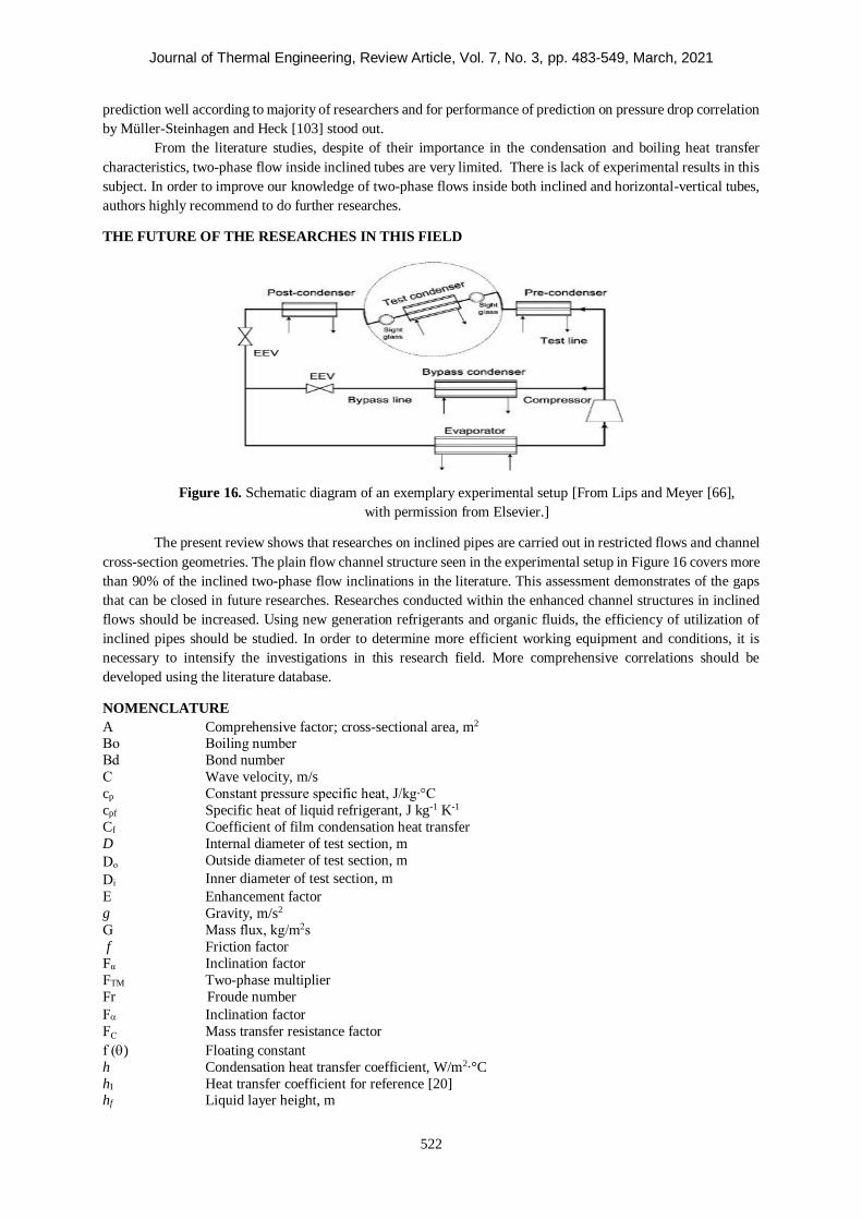
Journal of Thermal Engineering, Review Article, Vol. 7, No. 3, pp. 483-549, March, 2021
522
prediction well according to majority of researchers and for performance of prediction on pressure drop correlation
by Müller-Steinhagen and Heck [103] stood out.
From the literature studies, despite of their importance in the condensation and boiling heat transfer
characteristics, two-phase flow inside inclined tubes are very limited. There is lack of experimental results in this
subject. In order to improve our knowledge of two-phase flows inside both inclined and horizontal-vertical tubes,
authors highly recommend to do further researches.
THE FUTURE OF THE RESEARCHES IN THIS FIELD
Figure 16. Schematic diagram of an exemplary experimental setup [From Lips and Meyer [66],
with permission from Elsevier.]
The present review shows that researches on inclined pipes are carried out in restricted flows and channel
cross-section geometries. The plain flow channel structure seen in the experimental setup in Figure 16 covers more
than 90% of the inclined two-phase flow inclinations in the literature. This assessment demonstrates of the gaps
that can be closed in future researches. Researches conducted within the enhanced channel structures in inclined
flows should be increased. Using new generation refrigerants and organic fluids, the efficiency of utilization of
inclined pipes should be studied. In order to determine more efficient working equipment and conditions, it is
necessary to intensify the investigations in this research field. More comprehensive correlations should be
developed using the literature database.
NOMENCLATURE
A Comprehensive factor; cross-sectional area, m2
Bo Boiling number
Bd Bond number
C Wave velocity, m/s
cp Constant pressure specific heat, J/kg∙°C
cpf Specific heat of liquid refrigerant, J kg-1 K-1
Cf Coefficient of film condensation heat transfer
D Internal diameter of test section, m
Do Outside diameter of test section, m
Di Inner diameter of test section, m
E Enhancement factor
g Gravity, m/s2
G Mass flux, kg/m2s
f Friction factor
Fα Inclination factor
FTM Two-phase multiplier
Fr Froude number
F Inclination factor
FC Mass transfer resistance factor
f () Floating constant
h Condensation heat transfer coefficient, W/m2∙°C
hI Heat transfer coefficient for reference [20] hf Liquid layer height, m
Journal of Thermal Engineering, Review Article, Vol. 7, No. 3, pp. 483-549, March, 2021
523
Hf Liquid hold-up
hfv Latent heat of vaporisation, J/kg
hm,o Mean overall heat transfer coefficient for the whole pipe surface, W/m2∙°C
hNu Nusselt condensation heat transfer coefficient, W/m2∙°C
i'fv Rohsenow’s modified latent heat of vaporisation, J/kg
Jv Dimensionless velocity
k Thermal conductivity of tube material, W/m∙K
Nu Nusselt number Nuort Nusselt number for reference [22]
p Gradient parameter
pr Reduced pressure
Pr Prandtl number
Prl Liquid Prandtl number
Prf Fluid Prandtl number
𝑞 Heat flux, W/m2
qdry Dry angle,
R Radius of test pipe
Re Reynolds number s Curvilinear abscissa, m
S A function of Prandtl number, Reynolds number and vapour quality
Twi Average inside test section wall temperature, K
v Velocity, m/s
V Voltage of electric heater, V
x Quality
Xtt Martinelli parameter
Z Shah’s correlating parameter, non-dimensional parameter for reference
Greek symbols
P Pressure drop, Pa
T Temperature difference, K
Surface tension, N m-2
ε Vapour void fraction
Liquid film thickness, m
Inclination angle,
f Fluid density, kg m-3
l Liquid density, kg m-3
Variation
Tbp Boiling temperature range, K
Subscripts
sm Smooth
a Average
b Bulk
out Outlet
i Inner
in Inlet out Outlet
o Outer
st Straight tube
Abbreviations
PH Pre-heater
Sat Saturation
TS Test section
MPE Mean percentage error
MAE Mean absolute error
RMSE Root mean square error
Journal of Thermal Engineering, Review Article, Vol. 7, No. 3, pp. 483-549, March, 2021
524
REFERENCES
[1] In S, Jeong S. Flow boiling heat transfer characteristics of R123 and R134a in a micro-channel.
International Journal of Multiphase Flow. 2009 Nov 1;35(11):987-1000.
[2] Ong CL, Thome JR. Flow boiling heat transfer of R134a, R236fa and R245fa in a horizontal 1.030 mm
circular channel. Experimental Thermal and Fluid Science. 2009 Apr 1;33(4):651-63.
[3] Li W, Ma X, Sun ZC, He Y, Sherif SA, Zhang JH, Zhu HT. Evaporation heat transfer characteristics of
R410A inside horizontal three-dimensional enhanced tubes. International Journal of Thermal Sciences.
2019 Mar 1;137:456-66.
[4] Akhavan-Behabadi MA, Esmailpour M. Experimental study of evaporation heat transfer of R-134a inside
a corrugated tube with different tube inclinations. international communications in heat and mass transfer.
2014 Jul 1;55:8-14.
[5] Mohseni SG, Akhavan-Behabadi MA. Visual study of flow patterns during condensation inside a microfin
tube with different tube inclinations. International communications in heat and mass transfer. 2011 Oct
1;38(8):1156-61.
[6] Yu J, Jiang Y, Cai W, Li X, Zhu Z. Condensation flow patterns and heat transfer correction for zeotropic
hydrocarbon mixtures in a helically coiled tube. International Journal of Heat and Mass Transfer. 2019
Nov 1;143:118500.
[7] Estellé P, Cabaleiro D, Żyła G, Lugo L, Murshed SS. Current trends in surface tension and wetting
behavior of nanofluids. Renewable and Sustainable Energy Reviews. 2018 Oct 1;94:931-44.
[8] Saisorn S, Wongwises S. The effects of channel diameter on flow pattern, void fraction and pressure drop
of two-phase air–water flow in circular micro-channels. Experimental thermal and fluid science. 2010
May 1;34(4):454-62.
[9] Lips S, Meyer JP. Two-phase flow in inclined tubes with specific reference to condensation: a review.
International Journal of Multiphase Flow. 2011 Oct 1;37(8):845-59.
[10] Barnea D. A unified model for predicting flow-pattern transitions for the whole range of pipe inclinations.
International Journal of Multiphase Flow. 1987 Jan 1;13(1):1-2.
[11] Nitheanandan T, Soliman HM. Influence of tube inclination on the flow regime boundaries of condensing
steam. The Canadian Journal of Chemical Engineering. 1993 Feb;71(1):35-41.
[12] Wang WC, Ma XH, Wei ZD, Yu P. Two-phase flow patterns and transition characteristics for in-tube
condensation with different surface inclinations. International journal of heat and mass transfer. 1998 Oct
1;41(24):4341-9.
[13] Ghajar AJ, Tang CC. Heat transfer measurements, flow pattern maps, and flow visualization for non-
boiling two-phase flow in horizontal and slightly inclined pipe. Heat Transfer Engineering. 2007 Jun
1;28(6):525-40.
[14] Kang Y, Davies III WA, Hrnjak P, Jacobi AM. Effect of inclination on pressure drop and flow regimes
in large flattened-tube steam condensers. Applied Thermal Engineering. 2017 Aug 1;123:498-513.
[15] Davies III WA, Hrnjak P. Heat transfer in a large, inclined, flattened-tube steam condenser. Heat Transfer
Engineering. 2020 Sep 24;41(17):1443-56.
[16] Cao S, Ji X, Xu J. R245fa condensation heat transfer in a phase separation condenser. Experimental
Thermal and Fluid Science. 2018 Nov 1;98:346-61.
[17] Lips S, Meyer JP. Effect of gravity forces on heat transfer and pressure drop during condensation of
R134a. Microgravity Science and Technology. 2012 Jun;24(3):157-64.
[18] Barbosa Jr JR, Ferreira JC, Hense D. Onset of flow reversal in upflow condensation in an inclinable tube.
Experimental Thermal and Fluid Science. 2016 Oct 1;77:55-70.
[19] Hanafizadeh P, Hojati A, Karimi A. Experimental investigation of oil–water two phase flow regime in an
inclined pipe. Journal of Petroleum Science and Engineering. 2015 Dec 1;136:12-22.
[20] Mozafari M, Akhavan-Behabadi MA, Qobadi-Arfaee H, Hanafizadeh P, Fakoor-Pakdaman M.
Experimental study on condensation flow patterns inside inclined U-bend tubes. Experimental Thermal
and Fluid Science. 2015 Nov 1;68:276-87.
[21] Xiao J, Hrnjak P. A new flow regime map and void fraction model based on the flow characterization of
condensation. International Journal of Heat and Mass Transfer. 2017 May 1;108:443-52.
[22] Park I, Mudawar I. Climbing film, flooding and falling film behavior in upflow condensation in tubes.
International Journal of Heat and Mass Transfer. 2013 Oct 1;65:44-61.
Journal of Thermal Engineering, Review Article, Vol. 7, No. 3, pp. 483-549, March, 2021
525
[23] El Hajal J, Thome JR, Cavallini A. Condensation in horizontal tubes, part 1: two-phase flow pattern map.
International Journal of Heat and Mass Transfer. 2003 Aug 1;46(18):3349-63.
[24] Thome JR, El Hajal J, Cavallini A. Condensation in horizontal tubes, part 2: new heat transfer model
based on flow regimes. International journal of heat and mass transfer. 2003 Aug 1;46(18):3365-87.
[25] Aroonrat K, Wongwises S. Experimental study on two-phase condensation heat transfer and pressure
drop of R-134a flowing in a dimpled tube. International Journal of Heat and Mass Transfer. 2017 Mar
1;106:437-48.
[26] Cavallini A, Censi G, Del Col D, Doretti L, Longo GA, Rossetto L. Experimental investigation on
condensation heat transfer and pressure drop of new HFC refrigerants (R134a, R125, R32, R410A,
R236ea) in a horizontal smooth tube. International Journal of Refrigeration. 2001 Jan 1;24(1):73-87.
[27] Nualboonrueng T, Wongwises S. Two-phase flow pressure drop of HFC-134a during condensation in
smooth and micro-fin tubes at high mass flux. International communications in heat and mass transfer.
2004 Oct 1;31(7):991-1004.
[28] Briggs A, Kelemenis C, Rose JW. Heat transfer and pressure drop measurements for in-tube condensation
of CFC-113 using microfin tubes and wire inserts. Experimental heat transfer. 2000 Jul 1;13(3):163-81.
[29] Macdonald M, Garimella S. Hydrocarbon condensation in horizontal smooth tubes: Part I–Measurements.
International Journal of Heat and Mass Transfer. 2016 Feb 1;93:75-85.
[30] Macdonald M, Garimella S. Hydrocarbon condensation in horizontal smooth tubes: Part II–Heat transfer
coefficient and pressure drop modeling. International Journal of Heat and Mass Transfer. 2016 Feb
1;93:1248-61.
[31] Kim SM, Kim J, Mudawar I. Flow condensation in parallel micro-channels–Part 1: Experimental results
and assessment of pressure drop correlations. International journal of heat and mass transfer. 2012 Jan
31;55(4):971-83.
[32] Son CH, Oh HK. Condensation pressure drop of R22, R134a and R410A in a single circular microtube.
Heat and Mass Transfer. 2012 Aug;48(8):1437-50.
[33] Liu N, Li JM, Sun J, Wang HS. Heat transfer and pressure drop during condensation of R152a in circular
and square microchannels. Experimental thermal and fluid science. 2013 May 1;47:60-7.
[34] Laohalertdecha S, Wongwises S. The effects of corrugation pitch on the condensation heat transfer
coefficient and pressure drop of R-134a inside horizontal corrugated tube. International Journal of Heat
and Mass Transfer. 2010 Jun 1;53(13-14):2924-31.
[35] Salimpour MR, Yarmohammadi S. Effect of twisted tape inserts on pressure drop during R-404A
condensation. International journal of refrigeration. 2012 Mar 1;35(2):263-9.
[36] Salimpour MR, Gholami H. Effect of inserting coiled wires on pressure drop of R-404A condensation.
International journal of refrigeration. 2014 Apr 1;40:24-30.
[37] Lips S, Meyer JP. Experimental study of convective condensation in an inclined smooth tube. Part II:
Inclination effect on pressure drops and void fractions. International Journal of Heat and Mass Transfer.
2012 Jan 15;55(1-3):405-12.
[38] Lips S, Meyer JP. Stratified flow model for convective condensation in an inclined tube. International
Journal of Heat and Fluid Flow. 2012 Aug 1;36:83-91.
[39] Ahn TH, Yun BJ, Jeong JJ, Kang KH, Park YS, Cheon J, Jerng DW. Development of a new condensation
model for the nearly-horizontal heat exchanger tube under the steam flowing conditions. International
Journal of Heat and Mass Transfer. 2014 Dec 1;79:876-84.
[40] Ahn T, Kang J, Bae B, Jeong JJ, Yun B. Steam condensation in horizontal and inclined tubes under
stratified flow conditions. International Journal of Heat and Mass Transfer. 2019 Oct 1;141:71-87.
[41] Würfel R, Kreutzer T, Fratzscher W. Turbulence transfer processes in adiabatic and condensing film flow
in an inclined tube. Chemical Engineering & Technology: Industrial Chemistry‐Plant Equipment‐Process
Engineering‐Biotechnology. 2003 Apr 9;26(4):439-48.
[42] Grolman E, Fortuin JM. Gas-liquid flow in slightly inclined pipes. Chemical engineering science. 1997
Dec 1;52(24):4461-71.
[43] Grolman E. Gas-Liquid Flow with Low Liquid Loading in Slightly Inclined Pipes. (Doctoral thesis) 1994
Retrieved from https://www.worldcat.org/title/gas-liquid-flow-with-low-liquid-loading-inslightly-
inclined-pipes/oclc/906984277#borrow
Journal of Thermal Engineering, Review Article, Vol. 7, No. 3, pp. 483-549, March, 2021
526
[44] Ottens M, Hoefsloot HC, Hamersma PJ. Correlations predicting liquid hold-up and pressure gradient in
steady-state (nearly) horizontal co-current gas-liquid pipe flow. Chemical Engineering Research and
Design. 2001 Jul 1;79(5):581-92.
[45] Zhang HQ, Wang Q, Sarica C, Brill JP. Unified model for gas-liquid pipe flow via slug dynamics—part
1: model development. J. Energy Resour. Technol.. 2003 Dec 1;125(4):266-73.
[46] Zhang HQ, Wang Q, Sarica C, Brill JP. Unified model for gas-liquid pipe flow via slug dynamics—Part
2: Model validation. J. Energy Resour. Technol.. 2003 Dec 1;125(4):274-83.
[47] Woldesemayat MA, Ghajar AJ. Comparison of void fraction correlations for different flow patterns in
horizontal and upward inclined pipes. International journal of multiphase flow. 2007 Apr 1;33(4):347-70.
[48] Woldesemayat MA. Comparison of void fraction correlations for two-phase flow in horizontal and
upward inclined flows (Doctoral dissertation, Oklahoma State University). 2006 Retrieved from https://sh
areok.org/bitstream/handle/11244/10090/Woldesemayat_okstate_0664M_1784.pdf?sequence=1
[49] Ewim DR, Meyer JP. Pressure drop during condensation at low mass fluxes in smooth horizontal and
inclined tubes. International Journal of Heat and Mass Transfer. 2019 Apr 1;133:686-701.
[50] Mozafari M, Akhavan-Behabadi MA, Qobadi-Arfaee H, Fakoor-Pakdaman M. Condensation and
pressure drop characteristics of R600a in a helical tube-in-tube heat exchanger at different inclination
angles. Applied Thermal Engineering. 2015 Nov 5;90:571-8.
[51] Li S, Jiang Y, Cai W, Li Q, Zhang H, Ren Y. The influence of structural parameters on heat transfer and
pressure drop for hydrocarbon mixture refrigerant during condensation in enhanced spiral pipes. Applied
Thermal Engineering. 2018 Jul 25;140:759-74.
[52] Jung D, Song KH, Cho Y, Kim SJ. Flow condensation heat transfer coefficients of pure refrigerants.
International Journal of Refrigeration. 2003 Jan 1;26(1):4-11.
[53] Zyhowski G, Brown A. Low global warming fluids for replacement of HFC-245fa and HFC-134a in ORC
applications. InHoneywell report, ORC2011 seminar, TU Delft in Netherlands 2011 Sep 23.
[54] Ghim G, Lee J. Condensation heat transfer of low GWP ORC working fluids in a horizontal smooth tube.
International Journal of Heat and Mass Transfer. 2017 Jan 1;104:718-28.
[55] Kim SM, Mudawar I. Flow condensation in parallel micro-channels–Part 2: Heat transfer results and
correlation technique. International Journal of Heat and Mass Transfer. 2012 Jan 31;55(4):984-94.
[56] Oh HK, Son CH. Condensation heat transfer characteristics of R-22, R-134a and R-410A in a single
circular microtube. Experimental thermal and fluid science. 2011 May 1;35(4):706-16.
[57] Yang Y, Jia L. Experimental investigation on heat transfer coefficient during upward flow condensation
of R410A in vertical smooth tubes. Journal of Thermal Science. 2015 Apr 1;24(2):155-63.
[58] Kondou C, Mishima F, Koyama S. Condensation and evaporation of R32/R1234ze (E) and
R744/R32/R1234ze (E) flow in horizontal microfin tubes. Science and Technology for the Built
Environment. 2015 Jul 4;21(5):564-77.
[59] Diani A, Cavallini A, Rossetto L. R1234yf condensation inside a 3.4 mm ID horizontal microfin tube.
International Journal of Refrigeration. 2017 Mar 1;75:178-89.
[60] Arslan G, Eskin N. Forced Convective Condensation of R134A Vapor Inside a Vertical Microfin Tube.
Experimental Heat Transfer. 2016 Nov 1;29(6):707-20.
[61] Miyara A, Nonaka K, Taniguchi M. Condensation heat transfer and flow pattern inside a herringbone-
type micro-fin tube. International journal of refrigeration. 2000 Mar 1;23(2):141-52.
[62] Yarmohammadi S, Farhadi M. Optimization of thermal and flow characteristics of R-404A vapor
condensation inside corrugated tubes. Experimental Thermal and Fluid Science. 2016 Dec 1;79:1-12.
[63] Li M, Guo Q, Lv J, Li D. Research on condensation heat transfer characteristics of R447A, R1234ze,
R134a and R32 in multi-port micro-channel tubes. International Journal of Heat and Mass Transfer. 2018
Mar 1;118:637-50.
[64] Meyer JP, Ewim DR. Heat transfer coefficients during the condensation of low mass fluxes in smooth
horizontal tubes. International Journal of Multiphase Flow. 2018 Feb 1;99:485-99.
[65] Akers WW, Deans HA, Crosser OK. Condensing heat transfer within horizontal tubes. Chem. Eng. Progr..
1958 Oct 1;54.
[66] Lips S, Meyer JP. Experimental study of convective condensation in an inclined smooth tube. Part I:
Inclination effect on flow pattern and heat transfer coefficient. International Journal of Heat and Mass
Transfer. 2012 Jan 15;55(1-3):395-404.
Journal of Thermal Engineering, Review Article, Vol. 7, No. 3, pp. 483-549, March, 2021
527
[67] Adelaja AO, Ewim DR, Dirker J, Meyer JP. An improved heat transfer correlation for condensation inside
inclined smooth tubes. International Communications in Heat and Mass Transfer. 2020 Oct 1;117:104746.
[68] Adelaja AO, Dirker J, Meyer JP. Convective condensation heat transfer of R134a in tubes at different
inclination angles. International Journal of Green Energy. 2016 Jun 20;13(8):812-21.
[69] Mohseni SG, Akhavan-Behabadi MA, Saeedinia M. Flow pattern visualization and heat transfer
characteristics of R-134a during condensation inside a smooth tube with different tube inclinations.
International Journal of Heat and Mass Transfer. 2013 May 1;60:598-602.
[70] Xing F, Xu J, Xie J, Liu H, Wang Z, Ma X. Froude number dominates condensation heat transfer of
R245fa in tubes: effect of inclination angles. International Journal of Multiphase Flow. 2015 May
1;71:98-115.
[71] Wang JC, Ma Y. Condensation heat transfer inside vertical and inclined thermosyphons. J. Heat Transfer.
1991 Aug 1;113(3):777-80.
[72] Wang BX, Du XZ. Study on laminar film-wise condensation for vapor flow in an inclined small/mini-
diameter tube. International journal of heat and mass transfer. 2000 May 15;43(10):1859-68.
[73] Yang JG, Ju XL, Ye S. An empirical correlation for steam condensing and flowing downward in a 50mm
diameter inclined tube. In Advanced Materials Research 2013 (Vol. 732, pp. 67-73). Trans Tech
Publications Ltd.
[74] Hussein HM, Mohamad MA, El-Asfouri AS. Theoretical analysis of laminar-film condensation heat
transfer inside inclined wickless heat pipes flat-plate solar collector. Renewable Energy. 2001 Jul 1;23(3-
4):525-35.
[75] Shah MM. An improved and extended general correlation for heat transfer during condensation in plain
tubes. Hvac&R Research. 2009 Sep 1;15(5):889-913.
[76] Shah MM. Comprehensive correlations for heat transfer during condensation in conventional and
mini/micro channels in all orientations. International journal of refrigeration. 2016 Jul 1;67:22-41.
[77] Camaraza-Medina Y, Hernandez-Guerrero A, Luviano-Ortiz JL, Mortensen-Carlson K, Cruz-Fonticiella
OM, García-Morales OF. New model for heat transfer calculation during film condensation inside pipes.
International Journal of Heat and Mass Transfer. 2019 Jan 1;128:344-53.
[78] Ewim DR, Meyer JP, Abadi SN. Condensation heat transfer coefficients in an inclined smooth tube at
low mass fluxes. International Journal of Heat and Mass Transfer. 2018 Aug 1;123:455-67.
[79] Akhavan-Behabadi MA, Kumar R, Mohseni SG. Condensation heat transfer of R-134a inside a microfin
tube with different tube inclinations. International Journal of Heat and Mass Transfer. 2007 Nov 1;50(23-
24):4864-71.
[80] Adelaja AO, Ewim DR, Dirker J, Meyer JP. Heat transfer, void fraction and pressure drop during
condensation inside inclined smooth and microfin tubes. Experimental Thermal and Fluid Science. 2019
Dec 1;109:109905.
[81] Khoeini, D., Akhavan-Behabadi, M. A., & Saboonchi, A. (2012). Experimental study of condensation
heat transfer of R-134a flow in corrugated tubes with different inclinations. International
Communications in Heat and Mass Transfer, 39(1), 138-143.
[82] Yildiz, S., Duymaz, G., Ziegler, F., & Auracher, H. (2017). Heat transfer during reflux condensation of
R134a inside a micro-fin tube with different tube inclinations. International Journal of Refrigeration, 74,
425-434.
[83] Ghiaasiaan, S. M. (2007). Two-phase flow, boiling, and condensation: in conventional and miniature
systems. Cambridge University Press.
[84] Julia, J. E., & Hibiki, T. (2011). Flow regime transition criteria for two-phase flow in a vertical
annulus. International Journal of Heat and Fluid Flow, 32(5), 993-1004
[85] Jepson, D. M., Azzopardi, B. J., & Whalley, P. B. (1989). The effect of gas properties on drops in annular
flow. International Journal of Multiphase Flow, 15(3), 327-339.
[86] Saisorn S, Kaew-On J, Wongwises S. An experimental investigation of flow boiling heat transfer of R-
134a in horizontal and vertical mini-channels. Exp Therm Fluid Sci [Internet]. 2013;46:232–44. Available
from: http://dx.doi.org/10.1016/j.expthermflusci.2012.12.015
[87] Wongwises, S., & Pipathattakul, M. (2006). Flow pattern, pressure drop and void fraction of two-phase
gas-liquid flow in an inclined narrow annular channel. Experimental Thermal and Fluid Science, 30(4),
345-354.
Journal of Thermal Engineering, Review Article, Vol. 7, No. 3, pp. 483-549, March, 2021
528
[88] Hernández, L., Julia, J. E., Ozar, B., Hibiki, T., & Ishii, M. (2011). Flow regime identification in boiling
two-phase flow in a vertical annulus. Journal of Fluids Engineering, 133(9), 091304.
[89] Layssac, T., Lips, S., & Revellin, R. (2019). Effect of inclination on heat transfer coefficient during flow
boiling in a mini-channel. International Journal of Heat and Mass Transfer, 132, 508-518.
[90] Krishnamurthy S, Peles Y. Flow boiling heat transfer on micro pin fins entrenched in a microchannel.
Journal of Heat Transfer. 2010 Apr 1;132(4).
[91] Zhang H, Wang S, Wang J. Experimental study on boiling flow of liquid nitrogen in inclined tubes—
Velocities and length distributions of Taylor bubbles. Journal of the Taiwan Institute of Chemical
Engineers. 2009 Jul 1;40(4):431-8.
[92] Cornwell K, Kew PA. Boiling in small parallel channels. InEnergy Efficiency in Process Technology
1993 (pp. 624-638). Springer, Dordrecht.
[93] Kandlikar SG, Steinke ME, Tian S, Campbell LA. High speed photographic observation of flow boiling
of water in parallel minichannels. In35th Proceedings of National Heat Transfer Conference 2001 Jun 10.
[94] Lakshminarasimhan MS, Hollingsworth DK, Witte LC. Boiling incipience in narrow channels. ASME-
PUBLICATIONS-HTD. 2000;366:55-64.
[95] Sardeshpande MV, Ranade VV. Two-phase flow boiling in small channels: A brief review. Sadhana.
2013 Dec 1;38(6):1083-126.
[96] Brutin D, Tadrist L. Pressure drop and heat transfer analysis of flow boiling in a minichannel: influence
of the inlet condition on two-phase flow stability. International journal of heat and mass transfer. 2004
May 1;47(10-11):2365-77.
[97] Zhang W, Hibiki T, Mishima K. Correlations of two-phase frictional pressure drop and void fraction in
mini-channel. International Journal of Heat and Mass Transfer. 2010 Jan 15;53(1-3):453-65.
[98] Chisholm D. A theoretical basis for the Lockhart-Martinelli correlation for two-phase flow. International
Journal of Heat and Mass Transfer. 1967 Dec 1;10(12):1767-78.
[99] Dukler AE, Wicks III M, Cleveland RG. Frictional pressure drop in two‐phase flow: B. An approach
through similarity analysis. AIChE Journal. 1964 Jan;10(1):44-51.
[100] Mishima K, Hibiki T. Some characteristics of air-water two-phase flow in small diameter vertical tubes.
International journal of multiphase flow. 1996 Aug 1;22(4):703-12.
[101] Celen A, Çebi A, Dalkılıç AS. Investigation of boiling heat transfer characteristics of R134a flowing in
smooth and microfin tubes. International Communications in Heat and Mass Transfer. 2018 Apr 1;93:21-
33.
[102] Tong W, Bergles AE, Jensen MK. Pressure drop with highly subcooled flow boiling in small-diameter
tubes. Experimental Thermal and Fluid Science. 1997 Oct 1;15(3):202-12.
[103] Müller-Steinhagen H, Heck K. A simple friction pressure drop correlation for two-phase flow in pipes.
Chemical Engineering and Processing: Process Intensification. 1986 Nov 1;20(6):297-308.
[104] Bandel J, Schlünder EU. Druckverlust und Wärmeübergang bei der Verdampfung siedender Kältemittel
im durchströmten Rohr. Chemie Ingenieur Technik. 1973 Mar;45(6):345-50.
[105] Yan J, Guo P, Bi Q, Liu Z, Zhang Q, Yang Z. Pressure drop for highly subcooled water flow boiling
under high heat and mass fluxes. Applied Thermal Engineering. 2017 Sep 1;124:1061-74.
[106] Tran TN, Chyu MC, Wambsganss MW, France DM. Two-phase pressure drop of refrigerants during flow
boiling in small channels: an experimental investigation and correlation development. International
Journal of Multiphase Flow. 2000 Nov 1;26(11):1739-54.
[107] Ribatski G, Wojtan L, Thome JR. An analysis of experimental data and prediction methods for two-phase
frictional pressure drop and flow boiling heat transfer in micro-scale channels. Experimental Thermal and
Fluid Science. 2006 Oct 1;31(1):1-9.
[108] Steinke ME, Kandlikar SG. Flow boiling and pressure drop in parallel flow microchannels.
InInternational Conference on Nanochannels, Microchannels, and Minichannels 2003 Jan 1 (Vol. 36673,
pp. 567-579).
[109] Yun R, Heo JH, Kim Y. Evaporative heat transfer and pressure drop of R410A in microchannels.
International journal of refrigeration. 2006 Jan 1;29(1):92-100.
[110] Yan YY, Lin TF. Evaporation heat transfer and pressure drop of refrigerant R-134a in a small pipe.
International Journal of Heat and Mass Transfer. 1998 Oct 1;41(24):4183-94.
Journal of Thermal Engineering, Review Article, Vol. 7, No. 3, pp. 483-549, March, 2021
529
[111] Mancin S, Diani A, Rossetto L. Experimental measurements of R134a flow boiling inside a 3.4-mm ID
microfin tube. Heat Transfer Engineering. 2015 Sep 22;36(14-15):1218-29.
[112] Park CY, Hrnjak PS. CO2 and R410A flow boiling heat transfer, pressure drop, and flow pattern at low
temperatures in a horizontal smooth tube. International Journal of Refrigeration. 2007 Jan 1;30(1):166-
78.
[113] Friedel L. Improved friction pressure drop correlation for horizontal and vertical two-phase pipe flow.
Proc. of European Two-Phase Flow Group Meet., Ispra, Italy, 1979. 1979.
[114] Kuo CS, Wang CC. Horizontal flow boiling of R22 and R407C in a 9.52 mm micro-fin tube. Applied
Thermal Engineering. 1996 Aug 1;16(8-9):719-31.
[115] Rollmann P, Spindler K. New models for heat transfer and pressure drop during flow boiling of R407C
and R410A in a horizontal microfin tube. International Journal of Thermal Sciences. 2016 May 1;103:57-
66.
[116] Didi MO, Kattan N, Thome JR. Prediction of two-phase pressure gradients of refrigerants in horizontal
tubes. International Journal of refrigeration. 2002 Nov 1;25(7):935-47.
[117] Kattan N. Contribution to the heat transfer analysis of substitute refrigerants in evaporator tubes with
smooth or enhanced tube surfaces.(Doctoral thesis, Verlag nicht ermittelbar).
[118] Lockhart RW. Proposed correlation of data for isothermal two-phase, two-component flow in pipes.
Chem. Eng. Prog.. 1949;45:39-48.
[119] Grönnerud R. Investigation of liquid hold-up, flow-resistance and heat transfer in circulation type
evaporators, part IV: two-phase flow resistance in boiling refrigerants. Bull. De l’Inst. Du Froid, Annexe.
1972;1.
[120] Chisholm D. Pressure gradients due to friction during the flow of evaporating two-phase mixtures in
smooth tubes and channels. International Journal of Heat and Mass Transfer. 1973 Feb 1;16(2):347-58.
[121] Bankoff SG. A variable density single-fluid model for two-phase flow with particular reference to steam-
water flow. Journal of Heat Transfer (US). 1960 Nov 1;82.
[122] Chawla JM. Wärmeübergang und Druckabfall in waagerechten Rohren bei der Strömung von
verdampfenden Kältemitteln. VDI-Verlag; 1967.
[123] Maddi MK, Rao DP. Experimental studies on flow boiling in inclined tubes: in the regions encountered
in solar collectors. The Canadian Journal of Chemical Engineering. 1995 Feb;73(1):73-84.
[124] Wang CC, Chang WJ, Dai CH, Lin YT, Yang KS. Effect of inclination on the convective boiling
performance of a microchannel heat sink using HFE-7100. Experimental thermal and fluid science. 2012
Jan 1;36:143-8.
[125] Jang Y, Park C, Lee Y, Kim Y. Flow boiling heat transfer coefficients and pressure drops of FC-72 in
small channel heat sinks. International journal of refrigeration. 2008 Sep 1;31(6):1033-41.
[126] Tshuva M, Barnea D, Taitel Y. Two-phase flow in inclined parallel pipes. International journal of
multiphase flow. 1999 Sep 1;25(6-7):1491-503.
[127] Laohalertdecha S, Wongwises S. An experimental study into the evaporation heat transfer and flow
characteristics of R-134a refrigerant flowing through corrugated tubes. International journal of
refrigeration. 2011 Jan 1;34(1):280-91.
[128] Piasecka M. Impact of selected parameters on refrigerant flow boiling heat transfer and pressure drop in
minichannels. International Journal of Refrigeration. 2015 Aug 1;56:198-212.
[129] García-Cascales JR, Vera-García F, Corberán-Salvador JM, Gonzálvez-Maciá J. Assessment of boiling
and condensation heat transfer correlations in the modelling of plate heat exchangers. International
Journal of Refrigeration. 2007 Sep 1;30(6):1029-41.
[130] Dalkilic AS, Teke İ, Wongwises S. Heat transfer enhancement during downward laminar flow
condensation of R134a in vertical smooth and microfin tubes. Isi Bilimi ve Teknigi Dergisi/Journal of
Thermal Science & Technology. 2012 Jun 1;32(1).
[131] Akhavan-Behabadi MA, Mohseni SG, Razavinasab SM. Evaporation heat transfer of R-134a inside a
microfin tube with different tube inclinations. Experimental thermal and fluid science. 2011 Sep
1;35(6):996-1001.
[132] Kandlikar SG. Fundamental issues related to flow boiling in minichannels and microchannels.
Experimental Thermal and Fluid Science. 2002 Jun 1;26(2-4):389-407.
Journal of Thermal Engineering, Review Article, Vol. 7, No. 3, pp. 483-549, March, 2021
530
[133] Gungor KE, Winterton RH. A general correlation for flow boiling in tubes and annuli. International
Journal of Heat and Mass Transfer. 1986 Mar 1;29(3):351-8.
[134] Cooper MG. Saturation nucleate pool boiling-a simple correlation. InIChemE Symp. Ser. 1984 (Vol. 86,
p. 786).
[135] Özdemir MR. Single-phase flow and flow boiling of water in rectangular metallic
microchannels (Doctoral dissertation, Brunel University London).
[136] Lazarek GM, Black SH. Evaporative heat transfer, pressure drop and critical heat flux in a small vertical
tube with R-113. International Journal of Heat and Mass Transfer. 1982 Jul 1;25(7):945-60.
[137] Li W, Wu Z. A general correlation for adiabatic two-phase pressure drop in micro/mini-channels.
International Journal of Heat and Mass Transfer. 2010 Jun 1;53(13-14):2732-9.
[138] Candan AY, Markal BU, Aydin OR, Avci ME. Saturated flow boiling characteristics in single rectangular
minichannels: effect of aspect ratio. Experimental Heat Transfer. 2018 Nov 2;31(6):531-51.
[139] Markal B, Aydin O, Avci M. Effect of aspect ratio on saturated flow boiling in microchannels.
International Journal of Heat and Mass Transfer. 2016 Feb 1;93:130-43.
[140] Markal B, Aydin O, Avci M. An experimental investigation of saturated flow boiling heat transfer and
pressure drop in square microchannels. International Journal of Refrigeration. 2016 May 1;65:1-1.
[141] Nedaei M. Subcooled flow boiling heat transfer enhancement in microchannels/tubes with modifications
of surface characteristics with micro/nano structures and films (Master’s dissertation).Retrieved from
https://tez.yok.gov.tr/UlusalTezMerkezi/
[142] Kandlikar SG. A general correlation for saturated two-phase flow boiling heat transfer inside horizontal
and vertical tubes.
[143] Passos JC, Kuser VF, Haberschill P, Lallemand M. Convective boiling of R-407c inside horizontal
microfin and plain tubes. Experimental thermal and fluid science. 2003 Jul 1;27(6):705-13.
[144] Dalkılıç AS, Özman C, Sakamatapan K, Wongwises S. Experimental investigation on the flow boiling of
R134a in a multi-microchannel heat sink. International Communications in Heat and Mass Transfer. 2018
Feb 1;91:125-37.
[145] Özdemir MR. Experimental study on single phase flow and boiling heat transfer in microchannels at high
flow rates(Master’s dissertation). Retrieved from https://tez.yok.gov.tr/UlusalTezMerkezi/
[146] Wambsganss MW, France DM, Jendrzejczyk JA, Tran TN. Boiling heat transfer in a horizontal small-
diameter tube.
[147] Reid RS, Pate MB, Bergles AE. Evaporation of refrigerant 113 flowing inside smooth tubes. American
Society of Mechanical Engineers, New York, NY; 1987 Jan 1.
[148] Tran TN, Wambsganss MW, France DM. Small circular-and rectangular-channel boiling with two
refrigerants. International Journal of Multiphase Flow. 1996 Jun 1;22(3):485-98.
[149] Kasza KE, Didascalou T, Wambsganss MW. Microscale flow visualization of nucleate boiling in small
channels: mechanisms influencing heat transfer. Argonne National Lab., IL (United States); 1997 Jul 1.
[150] Shiferaw D, Karayiannis TG, Kenning DB. Flow boiling in a 1.1 mm tube with R134a: Experimental
results and comparison with model. International Journal of Thermal Sciences. 2009 Feb 1;48(2):331-41.
[151] Ravigururajan TS, Cuta J, McDonald CE, Drost MK. Effects of heat flux on two-phase flow
characteristics of refrigerant flows in a micro-channel heat exchanger. American Society of Mechanical
Engineers, New York, NY (United States); 1996 Dec 31.
[152] Kundu A, Kumar R, Gupta A. Flow boiling heat transfer characteristics of R407C inside a smooth tube
with different tube inclinations. International journal of refrigeration. 2014 Sep 1;45:1-2.
[153] Kundu A, Kumar R, Gupta A. Evaporative heat transfer of R134a and R407C inside a smooth tube with
different inclinations. International Journal of Heat and Mass Transfer. 2014 Sep 1;76:523-33.
[154] Gang W, Bi Q, Wang H, Yang Z, Zhu X, Hu Z. Forced convection heat transfer using high temperature
and pressure water in an upward-inclined tube. Journal of heat transfer. 2012 Feb 1;134(2).
[155] Morcos SM, Mobarak A, Hilal M, Mohareb MR. Boiling heat transfer in horizontal and inclined
rectangular channels.
[156] Wang S, Yang D, Xie B, Wang L, Wang Y. Experimental investigation on heat transfer characteristics of
water in inclined downward tube of a supercritical pressure CFB boiler. Journal of Thermal Science. 2015
Oct;24(5):478-87.
[157] Jeong U, Kim SJ. Subcooling effect on boiling heat transfer of inclined downward-facing surface under
low flow and pressure. International Journal of Heat and Mass Transfer. 2018 Dec 1;127:182-95.
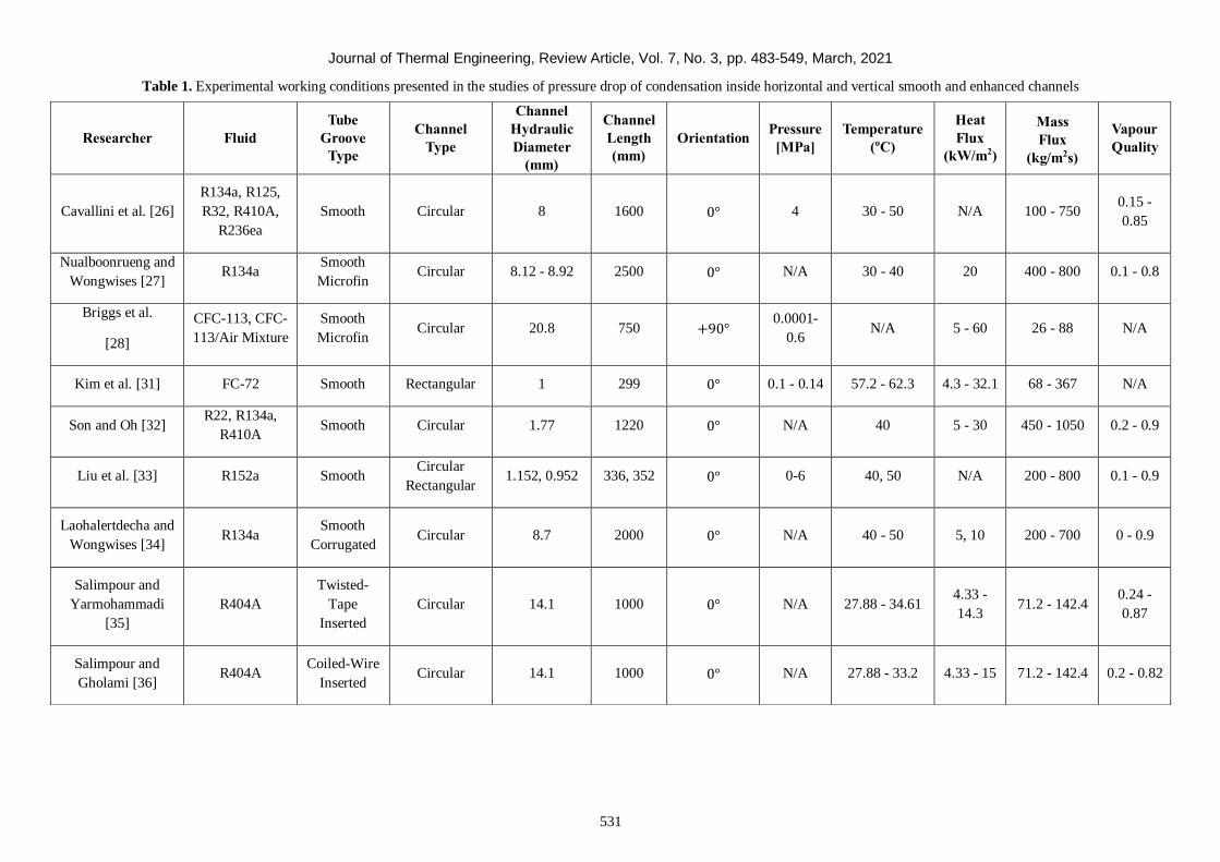
Journal of Thermal Engineering, Review Article, Vol. 7, No. 3, pp. 483-549, March, 2021
531
Table 1. Experimental working conditions presented in the studies of pressure drop of condensation inside horizontal and vertical smooth and enhanced channels
Researcher Fluid
Tube
Groove
Type
Channel
Type
Channel
Hydraulic
Diameter
(mm)
Channel
Length
(mm)
Orientation Pressure
[MPa]
Temperature
(oC)
Heat
Flux
(kW/m2)
Mass
Flux
(kg/m2s)
Vapour
Quality
Cavallini et al. [26]
R134a, R125,
R32, R410A,
R236ea
Smooth Circular 8 1600 0° 4 30 - 50 N/A 100 - 750 0.15 -
0.85
Nualboonrueng and
Wongwises [27] R134a
Smooth
Microfin Circular 8.12 - 8.92 2500 0° N/A 30 - 40 20 400 - 800 0.1 - 0.8
Briggs et al.
[28]
CFC-113, CFC-
113/Air Mixture
Smooth
Microfin Circular 20.8 750 +90°
0.0001-
0.6 N/A 5 - 60 26 - 88 N/A
Kim et al. [31] FC-72 Smooth Rectangular 1 299 0° 0.1 - 0.14 57.2 - 62.3 4.3 - 32.1 68 - 367 N/A
Son and Oh [32] R22, R134a,
R410A Smooth Circular 1.77 1220 0° N/A 40 5 - 30 450 - 1050 0.2 - 0.9
Liu et al. [33] R152a Smooth Circular
Rectangular 1.152, 0.952 336, 352 0° 0-6 40, 50 N/A 200 - 800 0.1 - 0.9
Laohalertdecha and
Wongwises [34] R134a
Smooth
Corrugated Circular 8.7 2000 0° N/A 40 - 50 5, 10 200 - 700 0 - 0.9
Salimpour and
Yarmohammadi
[35]
R404A
Twisted-
Tape
Inserted
Circular 14.1 1000 0° N/A 27.88 - 34.61 4.33 -
14.3 71.2 - 142.4
0.24 -
0.87
Salimpour and
Gholami [36] R404A
Coiled-Wire
Inserted Circular 14.1 1000 0° N/A 27.88 - 33.2 4.33 - 15 71.2 - 142.4 0.2 - 0.82
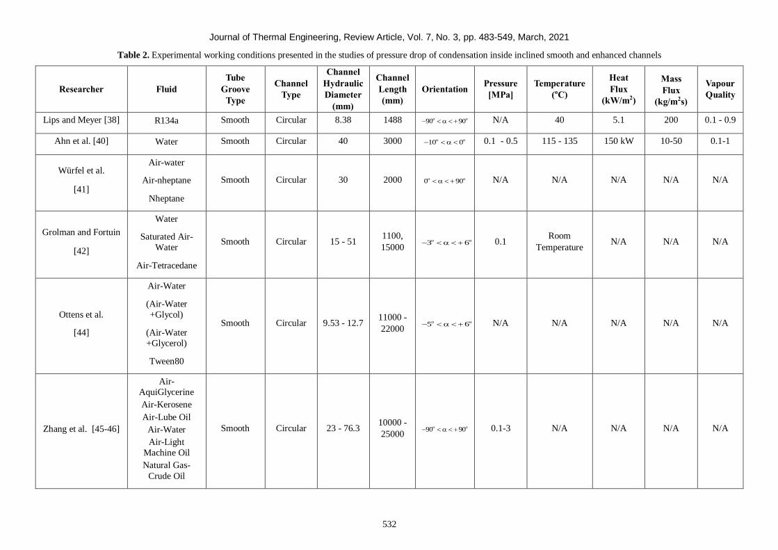
Journal of Thermal Engineering, Review Article, Vol. 7, No. 3, pp. 483-549, March, 2021
532
Table 2. Experimental working conditions presented in the studies of pressure drop of condensation inside inclined smooth and enhanced channels
Researcher Fluid
Tube
Groove
Type
Channel
Type
Channel
Hydraulic
Diameter
(mm)
Channel
Length
(mm)
Orientation Pressure
[MPa]
Temperature
(oC)
Heat
Flux
(kW/m2)
Mass
Flux
(kg/m2s)
Vapour
Quality
Lips and Meyer [38] R134a Smooth Circular 8.38 1488 90 90 o o N/A 40 5.1 200 0.1 - 0.9
Ahn et al. [40] Water Smooth Circular 40 3000 10 0 o o 0.1 - 0.5 115 - 135 150 kW 10-50 0.1-1
Würfel et al.
[41]
Air-water
Air-nheptane
Nheptane
Smooth Circular 30 2000 0 90 o o N/A N/A N/A N/A N/A
Grolman and Fortuin
[42]
Water
Saturated Air-
Water
Air-Tetracedane
Smooth Circular 15 - 51 1100,
15000 3 6 o o 0.1
Room
Temperature N/A N/A N/A
Ottens et al.
[44]
Air-Water
(Air-Water
+Glycol)
(Air-Water
+Glycerol)
Tween80
Smooth Circular 9.53 - 12.7 11000 -
22000 5 6 o o N/A N/A N/A N/A N/A
Zhang et al. [45-46]
Air-
AquiGlycerine
Air-Kerosene
Air-Lube Oil
Air-Water
Air-Light
Machine Oil
Natural Gas-
Crude Oil
Smooth Circular 23 - 76.3 10000 -
25000 90 90 o o 0.1-3 N/A N/A N/A N/A
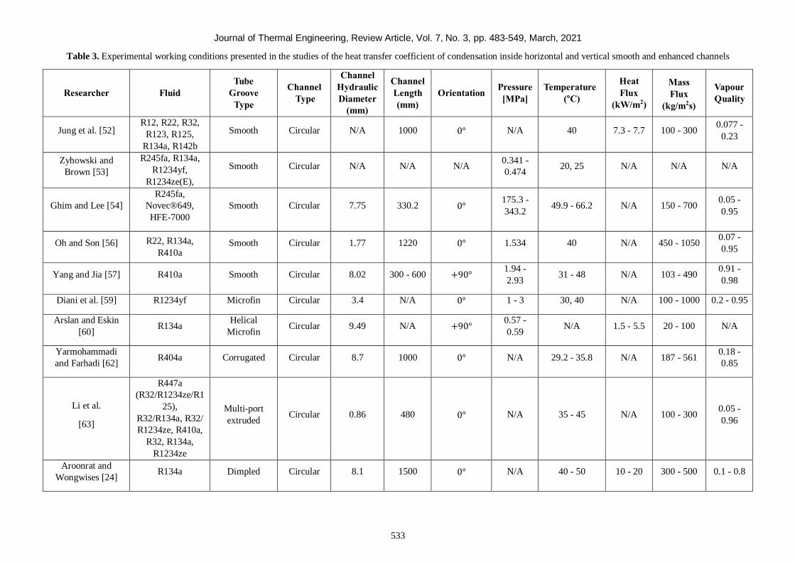
Journal of Thermal Engineering, Review Article, Vol. 7, No. 3, pp. 483-549, March, 2021
533
Table 3. Experimental working conditions presented in the studies of the heat transfer coefficient of condensation inside horizontal and vertical smooth and enhanced channels
Researcher Fluid
Tube
Groove
Type
Channel
Type
Channel
Hydraulic
Diameter
(mm)
Channel
Length
(mm)
Orientation Pressure
[MPa]
Temperature
(oC)
Heat
Flux
(kW/m2)
Mass
Flux
(kg/m2s)
Vapour
Quality
Jung et al. [52] R12, R22, R32,
R123, R125,
R134a, R142b
Smooth Circular N/A 1000 0° N/A 40 7.3 - 7.7 100 - 300 0.077 -
0.23
Zyhowski and
Brown [53]
R245fa, R134a,
R1234yf,
R1234ze(E),
Smooth Circular N/A N/A N/A 0.341 -
0.474 20, 25 N/A N/A N/A
Ghim and Lee [54]
R245fa,
Novec®649,
HFE-7000
Smooth Circular 7.75 330.2 0° 175.3 -
343.2 49.9 - 66.2 N/A 150 - 700
0.05 -
0.95
Oh and Son [56] R22, R134a,
R410a Smooth Circular 1.77 1220 0° 1.534 40 N/A 450 - 1050
0.07 -
0.95
Yang and Jia [57] R410a Smooth Circular 8.02 300 - 600 +90° 1.94 -
2.93 31 - 48 N/A 103 - 490
0.91 -
0.98
Diani et al. [59] R1234yf Microfin Circular 3.4 N/A 0° 1 - 3 30, 40 N/A 100 - 1000 0.2 - 0.95
Arslan and Eskin
[60] R134a
Helical
Microfin Circular 9.49 N/A +90°
0.57 -
0.59 N/A 1.5 - 5.5 20 - 100 N/A
Yarmohammadi
and Farhadi [62] R404a Corrugated Circular 8.7 1000 0° N/A 29.2 - 35.8 N/A 187 - 561
0.18 -
0.85
Li et al.
[63]
R447a
(R32/R1234ze/R1
25),
R32/R134a, R32/
R1234ze, R410a,
R32, R134a,
R1234ze
Multi-port
extruded Circular 0.86 480 0° N/A 35 - 45 N/A 100 - 300
0.05 -
0.96
Aroonrat and
Wongwises [24] R134a Dimpled Circular 8.1 1500 0° N/A 40 - 50 10 - 20 300 - 500 0.1 - 0.8
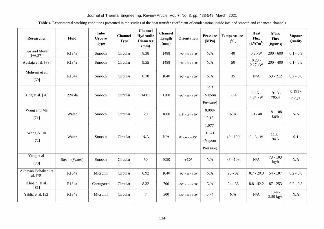
Journal of Thermal Engineering, Review Article, Vol. 7, No. 3, pp. 483-549, March, 2021
534
Table 4. Experimental working conditions presented in the studies of the heat transfer coefficient of condensation inside inclined smooth and enhanced channels
Researcher Fluid
Tube
Groove
Type
Channel
Type
Channel
Hydraulic
Diameter
(mm)
Channel
Length
(mm)
Orientation Pressure
[MPa]
Temperature
(oC)
Heat
Flux
(kW/m2)
Mass
Flux
(kg/m2s)
Vapour
Quality
Lips and Meyer
[66,37] R134a Smooth Circular 8.38 1488 90 90 o o N/A 40 0.2 kW 200 - 600 0.1 - 0.9
Adelaja et al. [68] R134a Smooth Circular 9.55 1488 90 90 o o N/A 50 0.23 -
0.27 kW 200 - 400 0.1 - 0.9
Mohseni et al.
[69] R134a Smooth Circular 8.38 1040 90 90 o o N/A 35 N/A 53 - 212 0.2 - 0.8
Xing et al. [70] R245fa Smooth Circular 14.81 1200 90 90 o o
40.5
(Vapour
Pressure)
55.4 1.16 -
4.34 kW
191.3 -
705.4
0.191 -
0.947
Wang and Ma
[71] Water Smooth Circular 20 1800 15 90 o o
0.008-
0.15 N/A 10 - 40
18 - 108
kg/h N/A
Wang & Du
[72] Water Smooth Circular N/A N/A 0 45 o o
1.077-
1.571
(Vapour
Pressure)
40 - 100 0 - 3 kW 11.3 -
94.5 0-1
Yang et al.
[73] Steam (Water) Smooth Circular 50 4050 +30° N/A 85 - 103 N/A
73 - 103
kg/h N/A
Akhavan-Behabadi et
al. [79] R134a Microfin Circular 8.92 1040 90 90 o o N/A 26 - 32 8.7 - 20.3 54 - 107 0.2 - 0.8
Khoeini et al.
[81] R134a Corrugated Circular 8.32 700 90 90 o o N/A 24 - 38 8.8 - 42.2 87 - 253 0.2 - 0.8
Yildiz et al. [82] R134a Microfin Circular 7 500 30 90 o o 0.74 N/A N/A 1.44 -
2.59 kg/s N/A
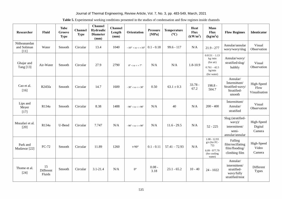
Journal of Thermal Engineering, Review Article, Vol. 7, No. 3, pp. 483-549, March, 2021
535
Table 5. Experimental working conditions presented in the studies of condensation and flow regimes inside channels
Researcher Fluid
Tube
Groove
Type
Channel
Type
Channel
Hydraulic
Diameter
(mm)
Channel
Length
(mm)
Orientation Pressure
[MPa]
Temperature
(oC)
Heat
Flux
(kW/m2)
Mass
Flux
(kg/m2s)
Flow Regimes Identicator
Nitheanandan
and Soliman
[11]
Water Smooth Circular 13.4 1040 10 10 o o 0.1 - 0.18 99.6 - 117 N/A
21.9 - 277 Annular/annular
wavy/wavy/slug
Visual
Observation
Ghajar and
Tang [13] Air-Water Smooth Circular 27.9 2790 0 7 o o N/A N/A 1.8-10.9
0.0131 – 1.13
kg /min
(for air)
0.761 – 42.5
kg/min
(for water)
Annular/wavy/
stratified/slug/
bubbly
Visual
Observation
Cao et al.
[16] R245fa Smooth Circular 14.7 1600 30 30 o o 0.50 63.1 ± 0.3
33.78 -
67.2
198.8 -
504.7
Annular/
İntermittent/
Stratified-wavy/
Stratified-
smooth
High-Speed
Flow
Visualisation
Lips and
Meyer
[17]
R134a Smooth Circular 8.38 1488 90 90 o o N/A 40 N/A
200 - 400
İntermittent/
Annular/
stratified
Visual
Observation
Mozafari et al.
[20] R134a U-Bend Circular 7.747 N/A 90 90 o o N/A 11.6 - 29.5 N/A 52 - 225
Slug (stratified-
wavy)/
intermittent/
semi-
annular/annular
High-Speed
Digital
Camera
Park and
Mudawar [22]
FC-72
Smooth Circular 11.89 1260 +90° 0.1 - 0.11 57.41 – 72.93 N/A
1.08 - 12.93
g/s (for FC-
72)
6.09 - 977.79
(for cooling
water)
Falling
film/oscillating
film/flooding/
climbing film
High-Speed
Video
Camera
Thome et al.
[24]
15
Different
Fluids
Smooth Circular 3.1-21.4 N/A 0° 0.08 -
3.18 23.1 - 65.2 10 - 40
24 - 1022
Annular/
intermittent/
stratified-
wavy/fully
stratified/mist
Different
Types
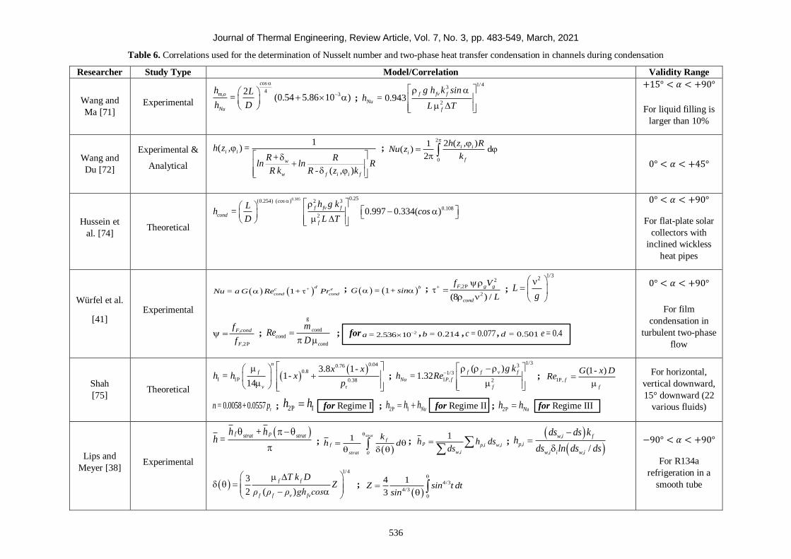
Journal of Thermal Engineering, Review Article, Vol. 7, No. 3, pp. 483-549, March, 2021
536
Table 6. Correlations used for the determination of Nusselt number and two-phase heat transfer condensation in channels during condensation
Researcher Study Type Model/Correlation Validity Range
Wang and
Ma [71] Experimental
432
(0.54 5.86 10 )
cos
m,o
Nu
h L=
h D ;
1/43
20.943
f fv f
Nu
f
g h k sin h =
L T
+15° < 𝛼 < +90°
For liquid filling is
larger than 10%
Wang and
Du [72]
Experimental &
Analytical
1( )
( )
i i
w
w f i i f
h z , =R+ R
ln ln RR k R - z , k
; 2
0
2 ( )1( ) d
2
i i
i
f
h z , RNu z
k
0° < 𝛼 < +45°
Hussein et
al. [74] Theoretical
0.385 0.25(0.254) ( ) 2 3
0.108
20.997 0.334( )
cos
f fv f
cond
f
h g kLh = cos
D L T
0° < 𝛼 < +90°
For flat-plate solar
collectors with
inclined wickless
heat pipes
Würfel et al.
[41] Experimental
1d
c + e
cond condNu = a G Re + Pr ; 1 b
G = + sin ; 2
2P
2(8 ) /
F, g g+
cond
f V
L ;
1/32
Lg
2P
F,cond
F,
f
f ;
d
d
d
con
con
con
mRe
D
g
; for 22.536 10a = , 0.214b = , 0.077c = , 0.501d = 0.4e=
0° < 𝛼 < +90°
For film
condensation in
turbulent two-phase
flow
Shah
[75] Theoretical
0.040.760.8
I 1P 0.38
r
3.8 11
14
n
f
v
x - xh = h - x
p ;
1/33
1/3
1 2
( )1.32
f f v f
Nu P, f
f
g kh = Re ;
1P,
(1 )
f
f
G - x DRe
r0.0058 0.0557n = + p ; 2P Ih h for Regime I ; 2P I Nuh h h for Regime II ; 2P Nuh h for Regime III
For horizontal,
vertical downward,
15° downward (22
various fluids)
Lips and
Meyer [38] Experimental
f pstrat strath +hh =
;
1 strat
ff
strat 0
kh d
;
1
p p,i w,i
w,i
h h dsds
;
/
w,i f
p,i
w,i i w,i
ds ds kh
ds ln ds ds
1/4
3
2 ( )
f f
f f v fv
T k DZ
ρ ρ ρ gh cos
;
4/3
4/3
0
4 1
3Z sin t dt
sin
−90° < 𝛼 < +90°
For R134a
refrigeration in a
smooth tube
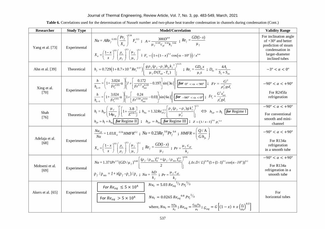
Journal of Thermal Engineering, Review Article, Vol. 7, No. 3, pp. 483-549, March, 2021
537
Table 6. Correlations used for the determination of Nusselt number and two-phase heat transfer condensation in channels during condensation (Cont.)
Researcher Study Type Model/Correlation Validity Range
Yang et al. [73] Experimental
0.34
0.193 0.3
f
f α
tt
PrNu = ARe F
X ;
0.8
0.145 0.34 0.66
300
f pf f
DA=
c k ;
(1 )f
f
GD - xRe =
0.5 0.10.91 fv
tt
f v
ρxX
x ρ
; 0.2 0.41 1 cos 10 / o
αF x x
For inclination angle
of +30º and better
prediction of steam
condensation in
larger-diameter
inclined tubes
Ahn et al. [39] Theoretical 0.25
3
4 0.57( )
0.729 1 8.7 10( )
f f v fv f
f v
f sat w
g - h kh Re
D T -T ;
hv
v
v
GD xRe = ;
4
v
hv
v int
AD
S S −3° < 𝛼 < 0°
Xing et al.
[70] Experimental
0.935 0.17 0.239
0
3.024 0.1721 0.197 sin 3
v ave
h= +
h Fr Fr x
for 0 90 o o ;
2
2
if
GFr =
ρ gd
0.935 0.584 0.654
0
3.024 0.241 1 0.03 sin 6
v ave
h= +
h Fr Fr x
for 90 0 o o ;
2 2
2
i
ave
v
v
G xFr =
ρ gd
−90° < 𝛼 < +90°
For R245fa
refrigeration
Shah
[76] Theoretical
I 1P 0.95
3.81
14 Z
n
f
g
h = h
;
1/33
1/3
1 2
( )1.32
f f v f
Nu P, f
f
g kh = Re
2P Ih h for Regime I
2P I Nuh h h for Regime II ; 2P Nuh h for Regime III ;
0.8 0.4
r1/ 1Z x - p
−90° < 𝛼 < +90°
For conventional
smooth and mini-
channel
Adelaja et al.
[68] Experimental
0.56 0.22P 1.03
tt
Nu= X HMFR
Nu ;
0.8 0.40.23 f fNu = Re Pr ; v
/ A f
QHMFR
G h
0.5 0.10.91 fv
tt
f v
ρxX
x ρ
; (1 )
f
f
GD - xRe =
;
c f pf
f
Pr =k
−90° < 𝛼 < +90°
For R134a
refrigeration
in a smooth tube
Mohseni et al.
[69] Experimental
0.910.5 0.5
1/3 0.69 0.29 0.1 0.1( / ) ( / )
1.371 ( / ) ( / ) (1 (1 1) ( ))2
f mix in f mix out o
f
+Nu = Pr GD . Δx.D L - cos α -10
/ ( ) / f mix f v v= 1+ x - ; f
hDNu =
k ;
c f pf
f
Pr =k
−90° < 𝛼 < +90°
For R134a refrigeration in a
smooth tube
Akers et al. [65]
Experimental
𝑁𝑢𝑙 = 5.03 𝑅𝑒𝑒𝑞
13⁄ 𝑃𝑟𝑙
13⁄
𝑁𝑢𝑙 = 0.0265 𝑅𝑒𝑒𝑞0.8 𝑃𝑟𝑙
13⁄
where, 𝑁𝑢𝑙 =ℎ𝐷ℎ
𝑘𝑙 ; 𝑅𝑒𝑒𝑞 =
𝐺𝑒𝑞𝐷ℎ
𝜇𝑙 ;
𝐺𝑒𝑞
= 𝐺 [(1 − 𝑥) + 𝑥 (𝜌𝑙
𝜌𝑣)
0.5
]
For
horizontal tubes For 𝑅𝑒𝑒𝑞 > 5 × 10⁴
For 𝑅𝑒𝑒𝑞 ≤ 5 × 10⁴
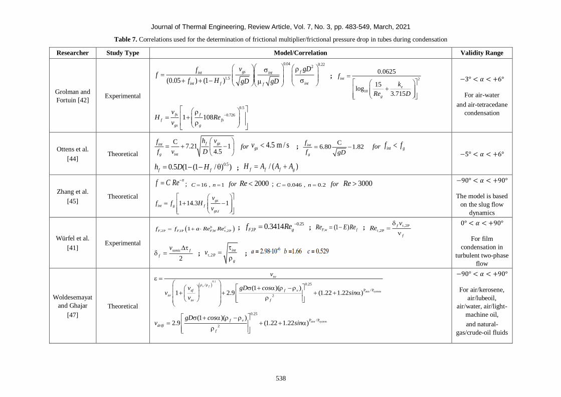
Journal of Thermal Engineering, Review Article, Vol. 7, No. 3, pp. 483-549, March, 2021
538
Table 7. Correlations used for the determination of frictional multiplier/frictional pressure drop in tubes during condensation
Researcher Study Type Model/Correlation Validity Range
Grolman and
Fortuin [42] Experimental
0.04 0.222
1.5(0.05 ) (1 )
gs fint int
intint f f
v gDff
f H gD gD
;
2
10
0.0625
15log
3.715
int
e
g
f
k
Re D
0.5
0.7261 108fs f
f fs
gs g
vH Re
v
−3° < 𝛼 < +6°
For air-water
and air-tetracedane
condensation
Ottens et al.
[44] Theoretical
C7.21 1
4.5
f gsint
g int
h vf
f v D
for 4.5 m / sgsv ;
C6.80 1.82int
g
f
f gD for int gf f
0.50.5 (1 (1 / ) )f fh D H ; / ( )f f f gH A A A
−5° < 𝛼 < +6°
Zhang et al.
[45] Theoretical
nf C Re ; 16 , 1 C n for 2000Re ; 0.046 , 0.2 C n for 3000Re
1 14.3 1gs
int g f
gs,t
vf f H
v
−90° < 𝛼 < +90°
The model is based
on the slug flow
dynamics
Würfel et al.
[41] Experimental
2P 1P 2P1 b c
F, F, F,W ,f f a Re Re ; 0.25
1P 0.3414 F, gf Re ; (1 ) F,w fRe E Re ; ,2P
2P
f
,
f
vRe
2
sonic f
f
v ; ,2 P
int
g
v ;
0° < 𝛼 < +90°
For film
condensation in
turbulent two-phase
flow
Woldesemayat
and Ghajar
[47]
Theoretical
0.1
atm system
0.25/
P /P
2
(1 )( )1 2.9 (1.22 1.22 )
v f
sv
sf f v
sv
sv f
v
v gD cosv sin
v
atm system
0.25
P /P
2
(1 )( )2.9 (1.22 1.22 )
f v
drift
f
gD cosv sin
−90° < 𝛼 < +90°
For air/kerosene,
air/lubeoil,
air/water, air/light-
machine oil,
and natural-
gas/crude-oil fluids
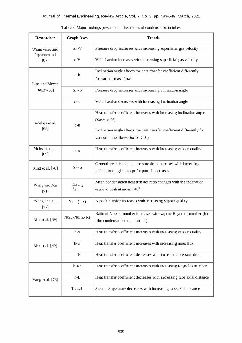
Journal of Thermal Engineering, Review Article, Vol. 7, No. 3, pp. 483-549, March, 2021
539
Table 8. Major findings presented in the studies of condensation in tubes
Researcher Graph Axes Trends
Wongwises and
Pipathattakul
[87]
ΔP-V Pressure drop increases with increasing superficial gas velocity
ɛ-V Void fraction increases with increasing superficial gas velocity
Lips and Meyer
[66,37-38]
α-h Inclination angle affects the heat transfer coefficient differently
for various mass flows
ΔP- α Pressure drop increases with increasing inclination angle
ɛ- α Void fraction decreases with increasing inclination angle
Adelaja et al.
[68] α-h
Heat transfer coefficient increases with increasing inclination angle
(for 𝛼 < 0°)
Inclination angle affects the heat transfer coefficient differently for
various mass flows (for 𝛼 < 0°)
Mohseni et al.
[69] h-x Heat transfer coefficient increases with increasing vapour quality
Xing et al. [70] ΔP- α General trend is that the pressure drop increases with increasing
inclination angle, except for partial decreases
Wang and Ma
[71]
m,o
Nu
h
h- α
Mean condensation heat transfer ratio changes with the inclination
angle to peak at around 400
Wang and Du
[72]
Nu – (1-x) Nusselt number increases with increasing vapour quality
Ahn et al. [39] Nulam/Nuturb- Re
Ratio of Nusselt number increases with vapour Reynolds number (for
film condensation heat transfer)
Ahn et al. [40]
h-x Heat transfer coefficient increases with increasing vapour quality
h-G Heat transfer coefficient increases with increasing mass flux
h-P Heat transfer coefficient decreases with increasing pressure drop
Yang et al. [73]
h-Re Heat transfer coefficient increases with increasing Reynolds number
h-L Heat transfer coefficient decreases with increasing tube axial distance
Tsteam-L Steam temperature decreases with increasing tube axial distance
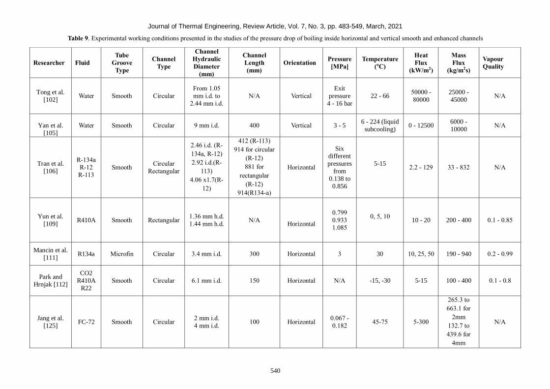
Journal of Thermal Engineering, Review Article, Vol. 7, No. 3, pp. 483-549, March, 2021
540
Table 9. Experimental working conditions presented in the studies of the pressure drop of boiling inside horizontal and vertical smooth and enhanced channels
Researcher Fluid
Tube
Groove
Type
Channel
Type
Channel
Hydraulic
Diameter
(mm)
Channel
Length
(mm)
Orientation Pressure
[MPa]
Temperature
(oC)
Heat
Flux
(kW/m2)
Mass
Flux
(kg/m2s)
Vapour
Quality
Tong et al.
[102]
Water Smooth Circular
From 1.05
mm i.d. to
2.44 mm i.d.
N/A Vertical
Exit
pressure
4 - 16 bar
22 - 66 50000 -
80000
25000 -
45000 N/A
Yan et al.
[105]
Water Smooth Circular
9 mm i.d.
400 Vertical 3 - 5 6 - 224 (liquid
subcooling) 0 - 12500
6000 -
10000 N/A
Tran et al.
[106]
R-134a
R-12
R-113
Smooth Circular
Rectangular
2.46 i.d. (R-
134a, R-12)
2.92 i.d.(R-
113)
4.06 x1.7(R-
12)
412 (R-113)
914 for circular
(R-12)
881 for
rectangular
(R-12)
914(R134-a)
Horizontal
Six
different
pressures
from
0.138 to
0.856
5-15
2.2 - 129 33 - 832 N/A
Yun et al.
[109] R410A Smooth Rectangular
1.36 mm h.d.
1.44 mm h.d. N/A
Horizontal
0.799
0.933
1.085
0, 5, 10
10 - 20 200 - 400 0.1 - 0.85
Mancin et al.
[111] R134a Microfin Circular 3.4 mm i.d. 300 Horizontal 3
30
10, 25, 50 190 - 940 0.2 - 0.99
Park and
Hrnjak [112]
CO2
R410A
R22
Smooth Circular 6.1 mm i.d. 150 Horizontal N/A -15, -30 5-15 100 - 400 0.1 - 0.8
Jang et al.
[125] FC-72 Smooth Circular
2 mm i.d.
4 mm i.d. 100 Horizontal
0.067 -
0.182 45-75 5-300
265.3 to
663.1 for
2mm
132.7 to
439.6 for
4mm
N/A
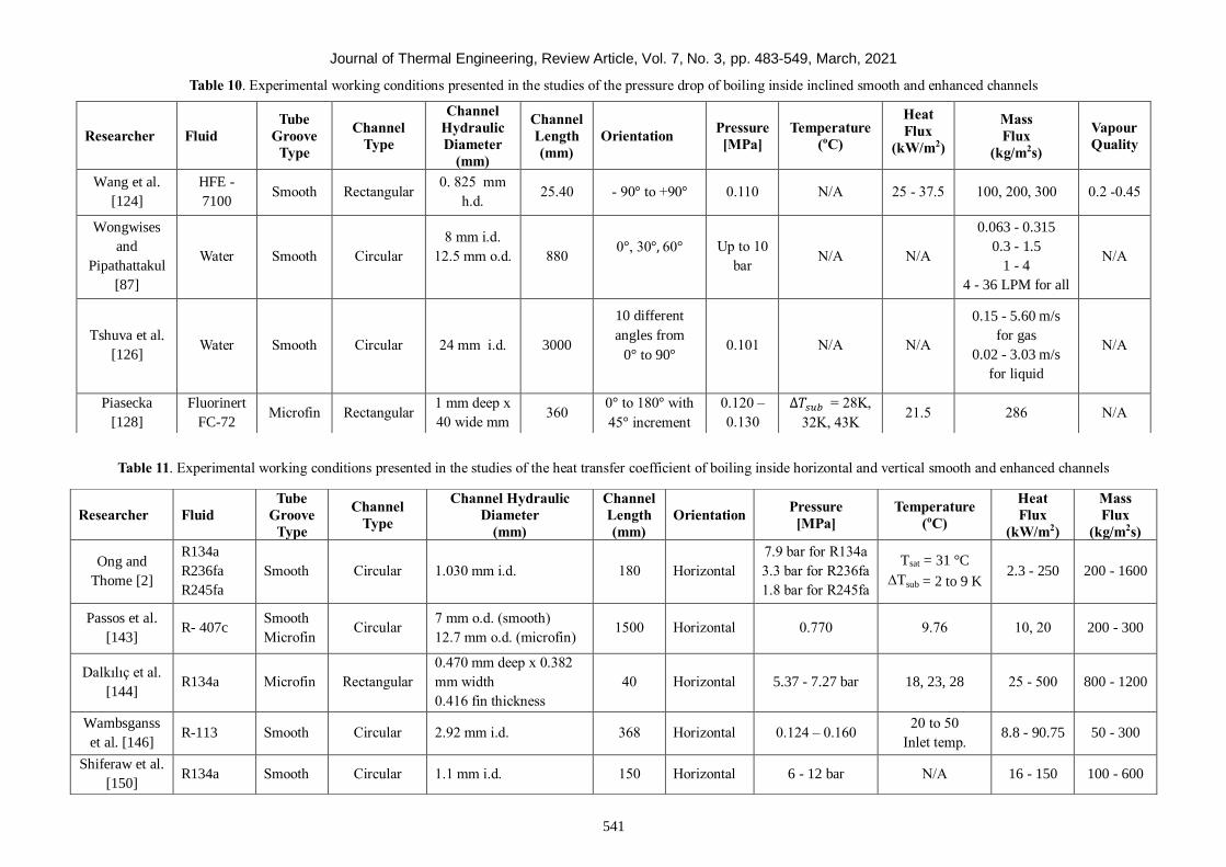
Journal of Thermal Engineering, Review Article, Vol. 7, No. 3, pp. 483-549, March, 2021
541
Table 10. Experimental working conditions presented in the studies of the pressure drop of boiling inside inclined smooth and enhanced channels
Table 11. Experimental working conditions presented in the studies of the heat transfer coefficient of boiling inside horizontal and vertical smooth and enhanced channels
Researcher Fluid
Tube
Groove
Type
Channel
Type
Channel
Hydraulic
Diameter
(mm)
Channel
Length
(mm)
Orientation Pressure
[MPa]
Temperature
(oC)
Heat
Flux
(kW/m2)
Mass
Flux
(kg/m2s)
Vapour
Quality
Wang et al.
[124]
HFE -
7100 Smooth Rectangular
0. 825 mm
h.d. 25.40 - 90° to +90° 0.110 N/A 25 - 37.5 100, 200, 300 0.2 -0.45
Wongwises
and
Pipathattakul
[87]
Water Smooth Circular
8 mm i.d.
12.5 mm o.d.
880 0°, 30°, 60°
Up to 10
bar N/A N/A
0.063 - 0.315
0.3 - 1.5
1 - 4
4 - 36 LPM for all
N/A
Tshuva et al.
[126] Water Smooth Circular 24 mm i.d. 3000
10 different
angles from
0° to 90°
0.101 N/A N/A
0.15 - 5.60 m/s
for gas
0.02 - 3.03 m/s
for liquid
N/A
Piasecka
[128]
Fluorinert
FC-72 Microfin Rectangular
1 mm deep x
40 wide mm 360
0° to 180° with
45° increment
0.120 –
0.130
∆𝑇𝑠𝑢𝑏 = 28K,
32K, 43K 21.5 286 N/A
Researcher Fluid
Tube
Groove
Type
Channel
Type
Channel Hydraulic
Diameter
(mm)
Channel
Length
(mm)
Orientation Pressure
[MPa]
Temperature
(oC)
Heat
Flux
(kW/m2)
Mass
Flux
(kg/m2s)
Ong and
Thome [2]
R134a
R236fa
R245fa
Smooth Circular 1.030 mm i.d. 180 Horizontal
7.9 bar for R134a
3.3 bar for R236fa
1.8 bar for R245fa
Tsat = 31 °C
∆Tsub = 2 to 9 K 2.3 - 250 200 - 1600
Passos et al.
[143] R- 407c
Smooth
Microfin Circular
7 mm o.d. (smooth)
12.7 mm o.d. (microfin) 1500 Horizontal 0.770 9.76 10, 20 200 - 300
Dalkılıç et al.
[144] R134a Microfin Rectangular
0.470 mm deep x 0.382
mm width
0.416 fin thickness
40 Horizontal 5.37 - 7.27 bar 18, 23, 28 25 - 500 800 - 1200
Wambsganss
et al. [146] R-113 Smooth Circular 2.92 mm i.d. 368 Horizontal 0.124 – 0.160
20 to 50
Inlet temp. 8.8 - 90.75 50 - 300
Shiferaw et al.
[150] R134a Smooth Circular 1.1 mm i.d. 150 Horizontal 6 - 12 bar N/A 16 - 150 100 - 600
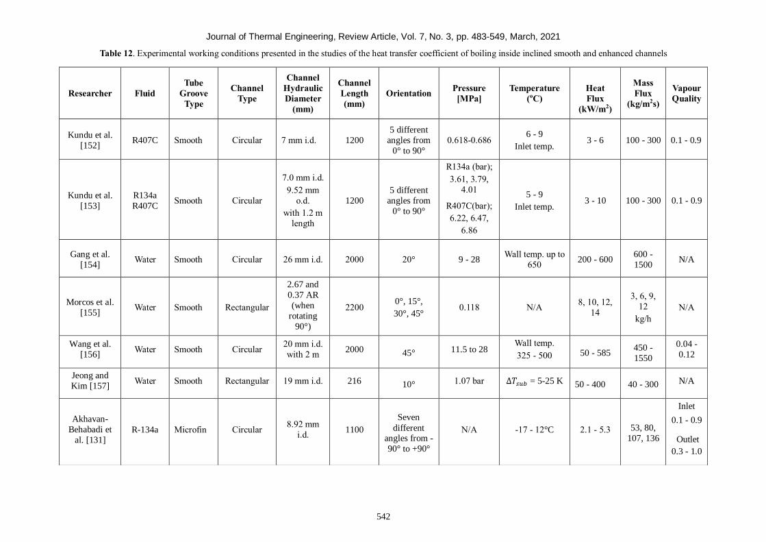
Journal of Thermal Engineering, Review Article, Vol. 7, No. 3, pp. 483-549, March, 2021
542
Table 12. Experimental working conditions presented in the studies of the heat transfer coefficient of boiling inside inclined smooth and enhanced channels
Researcher Fluid
Tube
Groove
Type
Channel
Type
Channel
Hydraulic
Diameter
(mm)
Channel
Length
(mm)
Orientation Pressure
[MPa]
Temperature
(oC)
Heat
Flux
(kW/m2)
Mass
Flux
(kg/m2s)
Vapour
Quality
Kundu et al.
[152] R407C Smooth Circular 7 mm i.d. 1200
5 different
angles from
0° to 90°
0.618-0.686 6 - 9
Inlet temp. 3 - 6 100 - 300 0.1 - 0.9
Kundu et al.
[153]
R134a
R407C Smooth Circular
7.0 mm i.d.
9.52 mm
o.d.
with 1.2 m
length
1200
5 different
angles from
0° to 90°
R134a (bar);
3.61, 3.79,
4.01
R407C(bar);
6.22, 6.47,
6.86
5 - 9
Inlet temp. 3 - 10 100 - 300 0.1 - 0.9
Gang et al.
[154] Water Smooth Circular 26 mm i.d. 2000 20° 9 - 28
Wall temp. up to
650
200 - 600
600 -
1500 N/A
Morcos et al.
[155] Water Smooth Rectangular
2.67 and
0.37 AR
(when
rotating
90°)
2200 0°, 15°,
30°, 45° 0.118 N/A
8, 10, 12,
14
3, 6, 9,
12
kg/h
N/A
Wang et al.
[156] Water Smooth Circular
20 mm i.d.
with 2 m 2000 45° 11.5 to 28
Wall temp.
325 - 500 50 - 585 450 -
1550
0.04 -
0.12
Jeong and
Kim [157] Water Smooth Rectangular 19 mm i.d. 216 10° 1.07 bar ∆𝑇𝑠𝑢𝑏 = 5-25 K 50 - 400 40 - 300 N/A
Akhavan-
Behabadi et
al. [131] R-134a Microfin Circular
8.92 mm
i.d. 1100
Seven
different angles from -
90° to +90°
N/A -17 - 12°C 2.1 - 5.3 53, 80,
107, 136
Inlet
0.1 - 0.9
Outlet
0.3 - 1.0
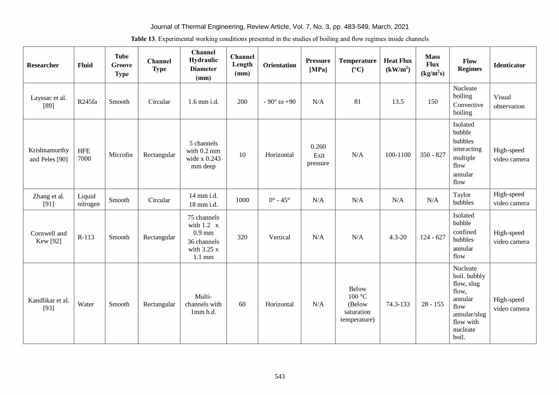
Journal of Thermal Engineering, Review Article, Vol. 7, No. 3, pp. 483-549, March, 2021
543
Table 13. Experimental working conditions presented in the studies of boiling and flow regimes inside channels
Researcher Fluid
Tube
Groove
Type
Channel
Type
Channel
Hydraulic
Diameter
(mm)
Channel
Length
(mm)
Orientation Pressure
[MPa]
Temperature
(°C)
Heat Flux
(kW/m2)
Mass
Flux
(kg/m2s)
Flow
Regimes Identicator
Layssac et al.
[89] R245fa Smooth Circular 1.6 mm i.d. 200 - 90° to +90 N/A 81 13.5 150
Nucleate
boiling
Convective
boiling
Visual
observation
Krishnamurthy
and Peles [90]
HFE
7000 Microfin Rectangular
5 channels
with 0.2 mm
wide x 0.243
mm deep
10 Horizontal
0.260
Exit
pressure
N/A 100-1100 350 - 827
Isolated
bubble
bubbles
interacting
multiple
flow
annular
flow
High-speed
video camera
Zhang et al.
[91]
Liquid
nitrogen Smooth Circular
14 mm i.d.
18 mm i.d. 1000 0° - 45° N/A N/A N/A N/A
Taylor
bubbles
High-speed
video camera
Cornwell and
Kew [92] R-113 Smooth Rectangular
75 channels
with 1.2 x
0.9 mm
36 channels
with 3.25 x
1.1 mm
320 Vertical N/A N/A 4.3-20 124 - 627
Isolated
bubble
confined
bubbles
annular
flow
High-speed
video camera
Kandlikar et al.
[93] Water Smooth Rectangular
Multi-
channels with
1mm h.d.
60 Horizontal N/A
Below
100 °C
(Below
saturation
temperature)
74.3-133 28 - 155
Nucleate
boil. bubbly
flow, slug
flow,
annular
flow
annular/slug
flow with
nucleate boil.
High-speed
video camera
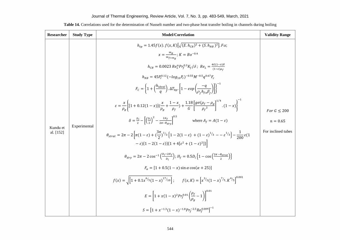
Journal of Thermal Engineering, Review Article, Vol. 7, No. 3, pp. 483-549, March, 2021
544
Table 14. Correlations used for the determination of Nusselt number and two-phase heat transfer boiling in channels during boiling
Researcher Study Type Model/Correlation Validity Range
Kundu et
al. [152]
Experimental
ℎ𝑡𝑝 = 1.45𝑓(𝑥). 𝑓(𝑥, 𝐾)[√(𝐸. ℎ𝐶𝐵)2 + (𝑆. ℎ𝑁𝐵 )2]. 𝐹;
𝑥 =𝑚𝑔
𝑚𝑓+𝑚𝑔
; 𝐾 = 𝐵𝑜−0.4
ℎ𝐶𝐵 = 0.0023 𝑅𝑒𝐿𝑛𝑃𝑟𝑓
0.3𝐾𝑓/ ; 𝑅𝑒𝐿 =4𝐺(1−𝑥)𝛿
(1− )𝜇𝑓
ℎ𝑁𝐵 = 45𝑃𝑟0.12(−𝑙𝑜𝑔10𝑃𝑟)−0.55𝑀−0.5𝑞0.67𝐹𝑐
𝐹𝐶 = {1 + (ℎ𝑖𝑑𝑒𝑎𝑙
𝑞) . ∆𝑇𝑏𝑝 . [1 − 𝑒𝑥𝑝 (
−𝑞
𝑓
ℎ𝑓𝑓
)]}
−1
휀 =𝑥
𝜌𝑔
{[1 + 0.12(1 − 𝑥)](𝑥
𝜌𝑔
+1 − 𝑥
𝜌𝑓
) +1.18
𝐺[𝑔𝜎(𝜌𝑓 − 𝜌𝑔
𝜌𝑓2
]
1 4⁄
. (1 − 𝑥)}
−1
𝛿 =𝐷𝑖
2− [(
𝐷𝑖
2)
2
−2𝐴𝑓
2𝜋−𝜃𝑑𝑟𝑦]
0.5
where 𝐴𝑓 = 𝐴(1 − 휀)
𝜃𝑠𝑡𝑟𝑎𝑡 = 2𝜋 − 2 [𝜋(1 − 휀) + (3𝜋
2)
13⁄ {1 − 2(1 − 휀) + (1 − 휀)
13 ⁄ − − 휀
13⁄ } −
1
200휀(1
− 휀){1 − 2(1 − 휀)}{1 + 4[휀2 + (1 − 휀)2]}]
𝜃𝑑𝑟𝑦 = 2𝜋 − 2 cos−1 (𝐷𝑖−2𝐻𝑓
𝐷𝑖) ; 𝐻𝑓 = 0.5𝐷𝑖 {1 − cos (
2𝜋 −𝜃𝑠𝑡𝑟𝑎𝑡
2)}
𝐹𝛼 = [1 + 0.5(1 − 𝑥) sin 𝛼 cos(𝛼 + 25)]
𝑓(𝑥) = √[1 + 0.1𝑥6
5⁄ (1 − 𝑥)17
10⁄ ] ; 𝑓(𝑥, 𝐾) = [𝑥3
2⁄ (1 − 𝑥)7
5⁄ . 𝐾4
5⁄ ]0.001
𝐸 = [1 + 𝑥(1 − 𝑥)2𝑃𝑟𝑓0.01 (
𝜌𝑓
𝜌𝑔
− 1)]
0.01
𝑆 = [1 + 𝑥−1.3(1 − 𝑥)−1.8𝑃𝑟𝑓−2.5𝑅𝑒𝑓
0.009]−1
𝐹𝑜𝑟 𝐺 ≤ 200
𝑛 = 0.65
For inclined tubes
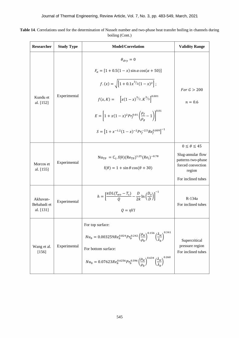
Journal of Thermal Engineering, Review Article, Vol. 7, No. 3, pp. 483-549, March, 2021
545
Table 14. Correlations used for the determination of Nusselt number and two-phase heat transfer boiling in channels during
boiling (Cont.)
Researcher Study Type Model/Correlation Validity Range
Kundu et
al. [152]
Experimental
𝜃𝑑𝑟𝑦 = 0
𝐹𝛼 = [1 + 0.5(1 − 𝑥) sin 𝛼 cos(𝛼 + 50)]
𝑓. (𝑥) = √[1 + 0.1𝑥3
2⁄ (1 − 𝑥)2] ;
𝑓(𝑥, 𝐾) = [𝑥(1 − 𝑥)3
2⁄ . 𝐾3
5⁄ ]0.001
𝐸 = [1 + 𝑥(1 − 𝑥)2𝑃𝑟𝑓0.01 (
𝜌𝑓
𝜌𝑔
− 1)]
0.01
𝑆 = [1 + 𝑥−1.2(1 − 𝑥)−2𝑃𝑟𝑓−2.5𝑅𝑒𝑓
0.009]−1
𝐹𝑜𝑟 𝐺 > 200
𝑛 = 0.6
Morcos et
al. [155]
Experimental
NuTP = C1. f()(ReTP)1.25(𝑅𝑒𝑙)−0.78
f(𝜃) = 1 + sin 𝜃 cos(𝜃 + 30)
0 ≤ 𝜃 ≤ 45
Slug-annular flow
patterns two-phase
forced convection
region
For inclined tubes
Akhavan-
Behabadi et
al. [131]
Experimental
ℎ = [𝜋𝐷𝐿(𝑇𝑤𝑜 − 𝑇𝑠)
𝑄−
𝐷
2𝑘ln (
𝐷𝑜
𝐷)]
−1
𝑄 = 𝜂𝑉𝐼
R-134a
For inclined tubes
Wang et al.
[156]
Experimental
For top surface:
𝑁𝑢𝑏 = 0.003259𝑅𝑒𝑏0.824𝑃𝑟𝑏
0.242 (𝜌𝑤
𝜌𝑏
)0.156
(𝜆𝑤
𝜆𝑏
)0.341
For bottom surface:
𝑁𝑢𝑏 = 0.07623𝑅𝑒𝑏0.6256𝑃𝑟𝑏
0.596 (𝜌𝑤
𝜌𝑏
)0.634
(𝜆𝑤
𝜆𝑏
)0.260
Supercritical
pressure region
For inclined tubes
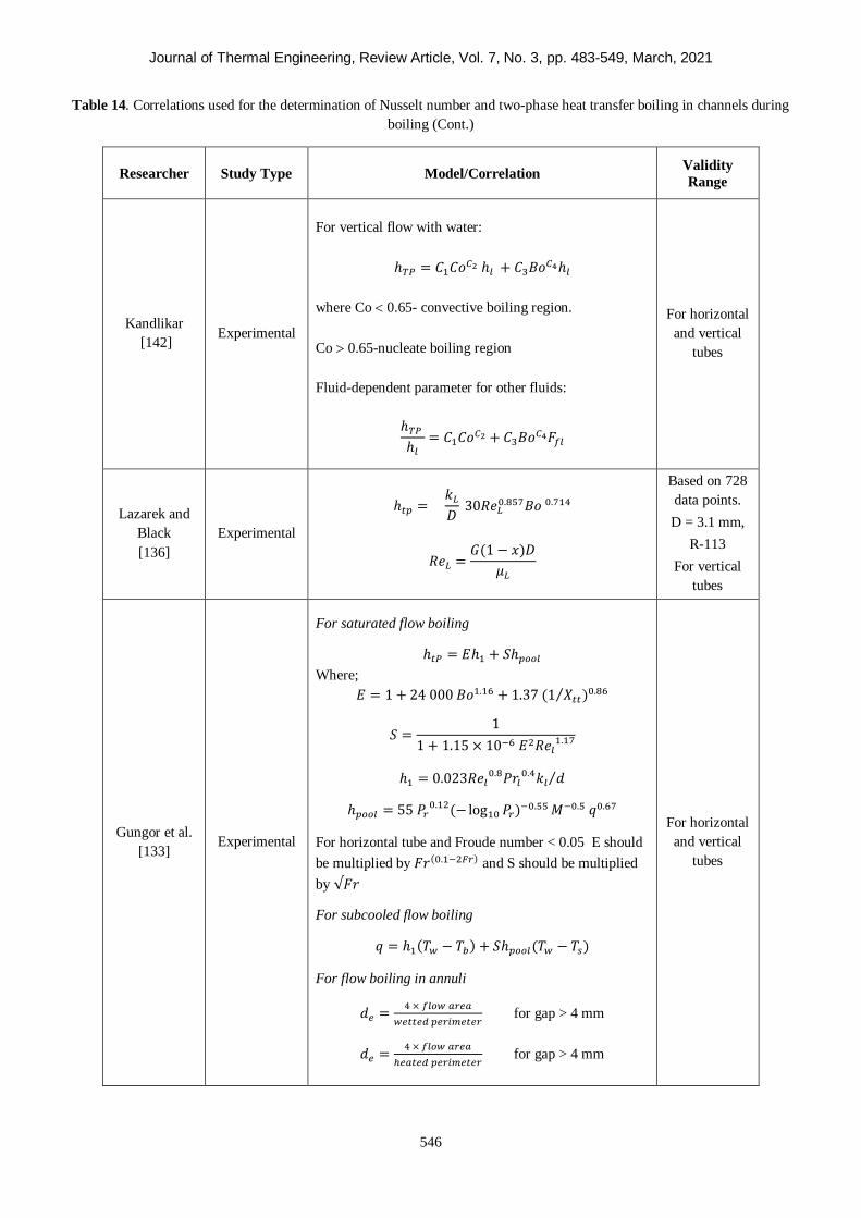
Journal of Thermal Engineering, Review Article, Vol. 7, No. 3, pp. 483-549, March, 2021
546
Table 14. Correlations used for the determination of Nusselt number and two-phase heat transfer boiling in channels during
boiling (Cont.)
Researcher Study Type Model/Correlation Validity
Range
Kandlikar
[142] Experimental
For vertical flow with water:
ℎ𝑇𝑃 = 𝐶1𝐶𝑜𝐶2 ℎ𝑙 + 𝐶3𝐵𝑜𝐶4ℎ𝑙
where Co 0.65- convective boiling region.
Co 0.65-nucleate boiling region
Fluid-dependent parameter for other fluids:
ℎ𝑇𝑃
ℎ𝑙
= 𝐶1𝐶𝑜𝐶2 + 𝐶3𝐵𝑜𝐶4𝐹𝑓𝑙
For horizontal
and vertical
tubes
Lazarek and
Black
[136]
Experimental
ℎ𝑡𝑝 = 𝑘𝐿
𝐷 30𝑅𝑒𝐿
0.857𝐵𝑜 0.714
𝑅𝑒𝐿 =𝐺(1 − 𝑥)𝐷
𝜇𝐿
Based on 728
data points.
D = 3.1 mm,
R-113
For vertical
tubes
Gungor et al.
[133] Experimental
For saturated flow boiling
ℎ𝑡𝑃 = 𝐸ℎ1 + 𝑆ℎ𝑝𝑜𝑜𝑙
Where;
𝐸 = 1 + 24 000 𝐵𝑜1.16 + 1.37 (1 𝑋𝑡𝑡⁄ )0.86
𝑆 =1
1 + 1.15 × 10⁻⁶ 𝐸2𝑅𝑒𝑙1.17
ℎ1 = 0.023𝑅𝑒𝑙0.8𝑃𝑟𝑙
0.4𝑘𝑙 𝑑⁄
ℎ𝑝𝑜𝑜𝑙 = 55 𝑃𝑟0.12(− log10 𝑃𝑟)−0.55 𝑀−0.5 𝑞0.67
For horizontal tube and Froude number < 0.05 E should
be multiplied by 𝐹𝑟(0.1−2𝐹𝑟) and S should be multiplied
by √𝐹𝑟
For subcooled flow boiling
𝑞 = ℎ1(𝑇𝑤 − 𝑇𝑏) + 𝑆ℎ𝑝𝑜𝑜𝑙(𝑇𝑤 − 𝑇𝑠)
For flow boiling in annuli
𝑑𝑒 =4 × 𝑓𝑙𝑜𝑤 𝑎𝑟𝑒𝑎
𝑤𝑒𝑡𝑡𝑒𝑑 𝑝𝑒𝑟𝑖𝑚𝑒𝑡𝑒𝑟 for gap > 4 mm
𝑑𝑒 =4 × 𝑓𝑙𝑜𝑤 𝑎𝑟𝑒𝑎
ℎ𝑒𝑎𝑡𝑒𝑑 𝑝𝑒𝑟𝑖𝑚𝑒𝑡𝑒𝑟 for gap > 4 mm
For horizontal
and vertical
tubes
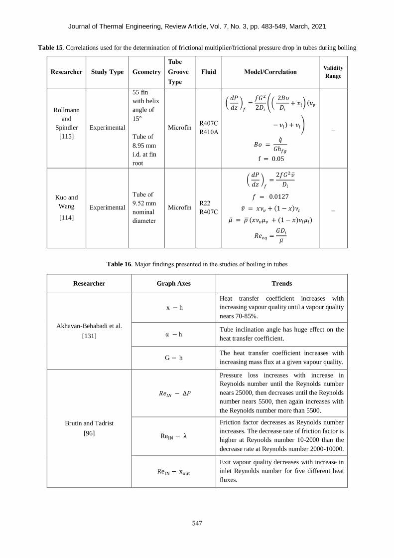
Journal of Thermal Engineering, Review Article, Vol. 7, No. 3, pp. 483-549, March, 2021
547
Table 15. Correlations used for the determination of frictional multiplier/frictional pressure drop in tubes during boiling
Researcher Study Type
Geometry
Tube
Groove
Type
Fluid Model/Correlation Validity
Range
Rollmann
and
Spindler
[115]
Experimental
55 fin
with helix
angle of
15°
Tube of
8.95 mm
i.d. at fin
root
Microfin
R407C
R410A
( 𝑑𝑃
𝑑𝑧 )
𝑓=
𝑓𝐺2
2𝐷𝑖
(( 2𝐵𝑜
𝐷𝑖
+ 𝑥𝑙) (𝜈𝑣
− 𝜈𝑙) + 𝜈𝑙)
𝐵𝑜 = ��
𝐺ℎ𝑓𝑔
f = 0.05
_
Kuo and
Wang
[114]
Experimental
Tube of
9.52 mm
nominal
diameter
Microfin
R22
R407C
( 𝑑𝑃
𝑑𝑧 )
𝑓=
2𝑓𝐺2��
𝐷𝑖
𝑓 = 0.0127
�� = 𝑥𝜈𝑣 + (1 − 𝑥)𝜈𝑙
�� = 𝜌 (𝑥𝜈𝑣𝜇𝑣 + (1 − 𝑥)𝜈𝑙𝜇𝑙)
𝑅𝑒𝑒𝑞 =𝐺𝐷𝑖
��
_
Table 16. Major findings presented in the studies of boiling in tubes
Researcher Graph Axes Trends
Akhavan-Behabadi et al.
[131]
x − h
Heat transfer coefficient increases with
increasing vapour quality until a vapour quality
nears 70-85%.
α − h Tube inclination angle has huge effect on the
heat transfer coefficient.
G − h The heat transfer coefficient increases with
increasing mass flux at a given vapour quality.
Brutin and Tadrist
[96]
𝑅𝑒𝐼𝑁 − ∆𝑃
Pressure loss increases with increase in
Reynolds number until the Reynolds number
nears 25000, then decreases until the Reynolds
number nears 5500, then again increases with
the Reynolds number more than 5500.
ReIN − λ
Friction factor decreases as Reynolds number
increases. The decrease rate of friction factor is
higher at Reynolds number 10-2000 than the
decrease rate at Reynolds number 2000-10000.
ReIN − xout
Exit vapour quality decreases with increase in
inlet Reynolds number for five different heat
fluxes.
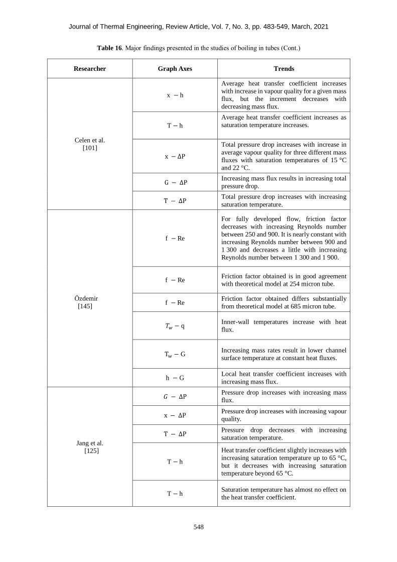
Journal of Thermal Engineering, Review Article, Vol. 7, No. 3, pp. 483-549, March, 2021
548
Table 16. Major findings presented in the studies of boiling in tubes (Cont.)
Researcher Graph Axes Trends
Celen et al.
[101]
x − h
Average heat transfer coefficient increases
with increase in vapour quality for a given mass
flux, but the increment decreases with
decreasing mass flux.
T − h
Average heat transfer coefficient increases as
saturation temperature increases.
x − ∆P
Total pressure drop increases with increase in
average vapour quality for three different mass
fluxes with saturation temperatures of 15 °C
and 22 °C.
G − ∆P Increasing mass flux results in increasing total
pressure drop.
T − ∆P Total pressure drop increases with increasing
saturation temperature.
Özdemir
[145]
f − Re
For fully developed flow, friction factor
decreases with increasing Reynolds number
between 250 and 900. It is nearly constant with
increasing Reynolds number between 900 and
1 300 and decreases a little with increasing
Reynolds number between 1 300 and 1 900.
f − Re Friction factor obtained is in good agreement
with theoretical model at 254 micron tube.
f − Re Friction factor obtained differs substantially
from theoretical model at 685 micron tube.
𝑇𝑤 − q Inner-wall temperatures increase with heat
flux.
Tw − G Increasing mass rates result in lower channel
surface temperature at constant heat fluxes.
h − G Local heat transfer coefficient increases with
increasing mass flux.
Jang et al.
[125]
𝐺 − ∆P Pressure drop increases with increasing mass
flux.
x − ∆P Pressure drop increases with increasing vapour
quality.
T − ∆P Pressure drop decreases with increasing
saturation temperature.
T − h
Heat transfer coefficient slightly increases with
increasing saturation temperature up to 65 °C,
but it decreases with increasing saturation
temperature beyond 65 °C.
T − h Saturation temperature has almost no effect on
the heat transfer coefficient.
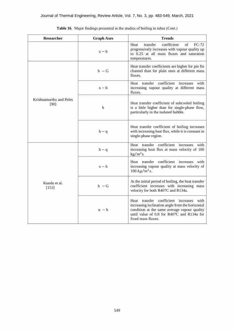
Journal of Thermal Engineering, Review Article, Vol. 7, No. 3, pp. 483-549, March, 2021
549
Table 16. Major findings presented in the studies of boiling in tubes (Cont.)
Researcher Graph Axes Trends
x − h
Heat transfer coefficient of FC-72
progressively increases with vapour quality up
to 0.25 at all mass fluxes and saturation
temperatures.
Krishnamurthy and Peles
[90]
h − G
Heat transfer coefficients are higher for pin fin
channel than for plain ones at different mass
fluxes.
x − h
Heat transfer coefficient increases with
increasing vapour quality at different mass
fluxes.
h
Heat transfer coefficient of subcooled boiling
is a little higher than for single-phase flow,
particularly in the isolated bubble.
h − q
Heat transfer coefficient of boiling increases
with increasing heat flux, while it is constant in
single-phase region.
Kundu et al.
[153]
h − q
Heat transfer coefficient increases with
increasing heat flux at mass velocity of 100
kg m2s⁄ .
x − h
Heat transfer coefficient increases with
increasing vapour quality at mass velocity of
100 𝑘𝑔 𝑚2𝑠⁄ .
h − G
At the initial period of boiling, the heat transfer
coefficient increases with increasing mass
velocity for both R407C and R134a.
α − h
Heat transfer coefficient increases with
increasing inclination angle from the horizontal
condition at the same average vapour quality
until value of 0.8 for R407C and R134a for
fixed mass fluxes.