Embed Size (px)
Citation preview
Compressed Air Treatment
Catalogue B002GB
Parker Hannifin UK LtdHermitage Court, Hermitage Lane, Maidstone, Kent ME16 9NT, EnglandPhone: +44 (0)1622 723 300 Fax: +44 (0)1622 728 703E-mail: [email protected] Web site: www.parker.com/balston
Parker Hannifin UK LtdHermitage Court, Hermitage Lane, Maidstone, Kent ME16 9NT, EnglandPhone: +44 (0)1622 723 300 Fax: +44 (0)1622 728 703E-mail: [email protected] Web site: www.parker.com/balston
2 3
Parker Filtration
Hydraulic,Lubrication & Coolant FiltrationHigh-performance filtrationsystems for production machineryin industrial, mobile andmilitary/marine applications.
Finite and Balston Compressed Air & Gas FiltrationComplete line of compressedair/gas filtration and separationproducts; coalescing, particulateand absorption filters and gasgenerators in many applications inmany industries.
Process & Chemical Fluid FiltrationLiquid filtration systems for foodand beverage, petrochemical/chemical processing, paint, inksand coating, electronics, oilfield and water
Racor Fuel Conditioning & FiltrationParker air, fuel and oil filtrationsystems provide quality protectionfor engines operating in anyenvironment, anywhere in the world.
System Contamination MonitoringOn-line dynamic particle analysis,off-line bottle sampling and fluidanalysis and measurement ofwater content polluting the oil inthe system. All important andachievable, cost-effective solutionsavailable to equipment manufacturersand end users alike with Parker Filtration’s range of system contamination monitors.
Problem Solving withParker Products
Consistent QualityTechnical Innovation
Premier Customer Service
Parker’s technical resources providethe correct filtration technologies that
conform to your requirements.That’s why thousands of
manufacturers and equipment usersaround the world rely on Parker
Filtration and people.
Worldwide Sales and Service
Parker Filtration’s global reputation asa reliable supplier of superior filtration
products is the result of a focusedand integrated development and
manufacturing system.
Parker Filtration consolidates qualityfiltration products into one broad
based range that covers manymarkets and applications.
Products are backed by Parker’scommitment to premier customer and
technical service worldwide.
Parker Filtration and Your Operation 4-5
Understanding Compressed Air Filtration 6-7
Analysing Compressed Air Quality – AQT4 8
Providing Air Free from Oil, Dirt and CondensateParker Filtration Media Grades 9Compressed Air Filters 1/4" to 1 1/2" 10-11Compressed Air Filters 2" to 3" 12-13Coded Compressed Air Filters 3" to 16" 14Miniature Point-of-Use Filters 15Pneumatic Filter Silencers 16Medium and High Pressure Filters 17Flow Rates 18
Producing Dry (Low Dewpoint) AirParker Membrane Technology 19System Membrane Dryers (SMD) 20-21Point-of-Use Membrane Dryers 22-23Desiccant Dryers 24
Saving Energy with Zero Air Loss Drains 25
Disposing of Compressed Air Condensate 26-28
Air Oil Separators 29
Useful Accessories 30
Par-Fit Alternative Elements 31-34
Sourcing Filters and Dryers for OEM Applications 35
Member of British Compressed
Air Society
Where Required
4 5Parker Hannifin UK LtdHermitage Court, Hermitage Lane, Maidstone, Kent ME16 9NT, EnglandPhone: +44 (0)1622 723 300 Fax: +44 (0)1622 728 703E-mail: [email protected] Web site: www.parker.com/balston
Parker Filtration Technologies at Work...
Parker Hannifin UK LtdHermitage Court, Hermitage Lane, Maidstone, Kent ME16 9NT, EnglandPhone: +44 (0)1622 723 300 Fax: +44 (0)1622 728 703E-mail: [email protected] Web site: www.parker.com/balston
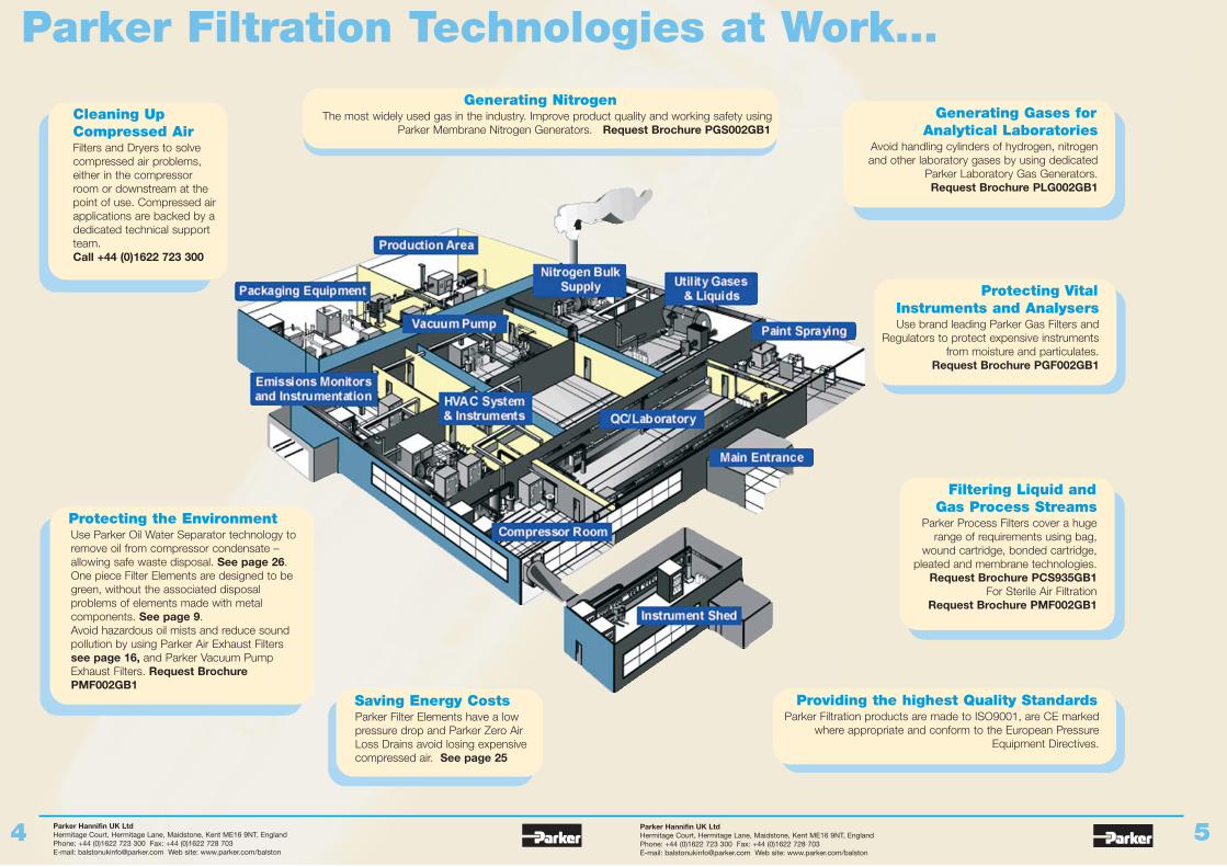
Generating Gases forAnalytical Laboratories
Avoid handling cylinders of hydrogen, nitrogenand other laboratory gases by using dedicated
Parker Laboratory Gas Generators. Request Brochure PLG002GB1
Protecting VitalInstruments and AnalysersUse brand leading Parker Gas Filters and
Regulators to protect expensive instrumentsfrom moisture and particulates.
Request Brochure PGF002GB1
Filtering Liquid andGas Process Streams
Parker Process Filters cover a hugerange of requirements using bag,
wound cartridge, bonded cartridge,pleated and membrane technologies.
Request Brochure PCS935GB1For Sterile Air Filtration
Request Brochure PMF002GB1
Providing the highest Quality StandardsParker Filtration products are made to ISO9001, are CE marked
where appropriate and conform to the European PressureEquipment Directives.
Saving Energy CostsParker Filter Elements have a low pressure drop and Parker Zero Air Loss Drains avoid losing expensive compressed air. See page 25
Protecting the EnvironmentUse Parker Oil Water Separator technology to remove oil from compressor condensate – allowing safe waste disposal. See page 26.One piece Filter Elements are designed to be green, without the associated disposal problems of elements made with metal components. See page 9.Avoid hazardous oil mists and reduce sound pollution by using Parker Air Exhaust Filters see page 16, and Parker Vacuum Pump Exhaust Filters. Request Brochure PMF002GB1
Cleaning Up Compressed AirFilters and Dryers to solve compressed air problems, either in the compressor room or downstream at the point of use. Compressed air applications are backed by a dedicated technical support team. Call +44 (0)1622 723 300
Generating NitrogenThe most widely used gas in the industry. Improve product quality and working safety using
Parker Membrane Nitrogen Generators. Request Brochure PGS002GB1
Parker Hannifin UK LtdHermitage Court, Hermitage Lane, Maidstone, Kent ME16 9NT, EnglandPhone: +44 (0)1622 723 300 Fax: +44 (0)1622 728 703E-mail: [email protected] Web site: www.parker.com/balston
Parker Hannifin UK LtdHermitage Court, Hermitage Lane, Maidstone, Kent ME16 9NT, EnglandPhone: +44 (0)1622 723 300 Fax: +44 (0)1622 728 703E-mail: [email protected] Web site: www.parker.com/balston
6 7
Compressed air is expensive to produceand must be properly treated in order tolimit maintenance costs, downtime andspoilage. Parker compressed air filtersremove the water, oil and dirt, which formthe contaminants of compressed air.
Protection where it’s needed…Stopping corrosion from compressed air at 20ºC and 7 barg requires an extremely low dewpoint of -30ºC, so even if an application is not particularly sensitive toimpurities – for example an air driven tool – it’sadvisable to have a point-of-use filter. Any rustparticles, pipe scale and water condensed out in theline will need to be removed or they will causeproblems.
Water, dirt, degraded oil and bacteria can form anabrasive sludge; this will bring with it higher coststhrough spoilt product, broken tools, increased air lineleakage and the resulting additional maintenancerequired. Parker compressed air filters provide you withthe protection you need from these contaminants. The diagrams (to the right) demonstrate the differentconfigurations of Parker compressed air filters anddryers to provide a variety of the ISO compressed airqualities.
Green and Lean – Protection that doesn’t cost the earth…Parker compressed air filter elements are manufacturedto offer advantages in addition to their great filtrationperformance. Parker elements have a self-supporting,rigid structure, this means that less of the world’svaluable resources are used in their construction whencompared with other designs. Also Parker are probablythe most cost effective elements on the market, givinga low cost of ownership. The design of Parker elementsmeans that they cost you less to use, since lowpressure drop is an inherent feature. This helps to keepdown the energy consumption of your compressed airsystem – an important consideration for users with theclimate change levy…
Why Parker offer such high efficiency with a low pressure drop…Parker compressed air filters are constructed from arandom bed of borosilicate glass fibres, which are heldin a rigid structure by a fluorocarbon resin binder. The diameter of these fibres is approximately onemicron, with the void spaces around the fibres beingmuch larger. This high proportion of space ensures alow flow resistance (pressure drop), and long life.
Collision, not sieving…Parker provides you with high efficiency filtrationthrough filters designed to use mechanisms thatcapture contaminants within the filter, whilstintermolecular forces act to hold the contaminants inthe filter.
When contaminants collide with a fibre they’recaptured. Intermolecular attraction is strong enough toprevent unloading of contaminants downstream, andwill permanently hold particulate.
'Coalescing' making big drops from little ones…A solid particle, once captured, cannot be removed. A liquid droplet, however, runs down the length of thefibre until it reaches a fibre crossover point. When manyliquid droplets run together, the liquid collected at thefibre crossover point becomes a larger droplet. Thelarger droplet is then gradually pushed through the fibremat by the flow of air or gas, picking up other dropletsalong the way, until it appears as a very large dropleton the downstream surface of the filter. Thus, the filterremoves very fine liquid droplets from the gas streamand converts them into large droplets of liquid, whichcan be readily drained from the system. This process iscalled "coalescing".
Why inside-to-outside flow?Since the coalesced liquid appears on the downstreamsurface after having passed completely through thefilter, the liquid will drip from this surface. In all Parkercoalescing filters, the flow direction through the filtercartridge is inside-to-outside. A Parker filter willcoalesce liquid droplets indefinitely without loss ofefficiency or flow capacity, because the liquid drainsfrom the filter cartridge as rapidly as it is collected.Only solid particles will cause a permanent increase inflow resistance; therefore, the useful life of the filter isdetermined only by the quantity of solids in the gas.
How to obtain a trouble-free coalescer…The mechanism of coalescing leads to two importantconsiderations in selecting and installing a coalescing filter:
I. Proper sizing of a Parker coalescing filter is easily done by using the maximum flow rate datain the charts (page 18).
II. To avoid liquid carryover, the coalesced liquid should not be allowed to build up in the filter housing above the level of the bottom of the filtercartridge. Rather than relying on operator attention to this easily overlooked job, automatic drains should be installed with all coalescing filters.
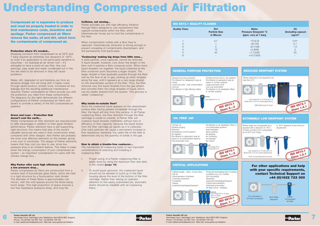
Understanding Compressed Air Filtration ISO 8573.1 QUALITY CLASSES
Quality Class Dirt Water OilParticle Size Pressure Dewpoint °C (Including vapour)
in Micron (ppm. vol.) at 7 barg mg/m3
1 0.1 -70 (0.3) 0.012 1 -40 (16) 0.13 5 -20 (128) 1.04 15 +3 (940) 55 40 +7 (1240) 256 - +10 (1500) -
GENERAL PURPOSE PROTECTION
‘OIL FREE’ AIR
CRITICAL APPLICATIONS
REDUCED DEWPOINT SYSTEM
EXTREMELY LOW DEWPOINT SYSTEM
General ring main protection Pre-filtration for refrigeration type airdryers Liquid and solid - bulk contaminationremoval Pre-filtration to high efficiency filters
Particle removal only in ‘dry systems’Pre-filtration to adsorption type airdryers in ‘oil free’ systemsLarge pneumatic tools Low cost automationPre-filtration to air sterilisation filtersin ‘oil-free’ systems
Where dewpoint is not required to beless than 2°C.
‘Oil-free’ airPipeline purgingRobotics Temperature control systemsAir logistics Pre-filtration to adsorption type airdryers in oil contaminated systems Fine pneumatic tools
Pre-filtration to air sterilisation filters inoil contaminated systemsInstrumentation Spray paintingAir gauging Air conveying Air bearings Air motors
Where totally dry compressed air isrequired with a dewpoint of -40°C.To stop corrosion from compressedair at 20°C and 7barg.
A -30°C dewpoint is the minimumrequirement.
Highest quality - clean, oil and odourfree airDecompression chambers Cosmetic productionFoodstuffs Dairies-production/packaging/transport
Production/packaging blow mouldingof plastics e.g. p.e.t. bottlesFilm processing Breweries-production/packaging/transportCritical instrumentationAdvanced pneumaticsAir-blast circuit - breakers
For other applications and helpwith your specific requirements,
contact Technical Support on +44 (0)1622 723 300
ISO 8573.1
Class 2.-.3 ISO 8573.1
Class 1.4.1
ISO 8573.1
Class 1.-.2 ISO 8573.1
Class 1.2.1
ISO 8573.1
Class 1.-.1
Oil Lubricated or Oil Free Compressor
Bulk WaterSeparator
ParkerCompressed
Air Filter
Use Grade DX or 10
Use Grade DX or 10 then BX or 6
Use Grade DX or 10 thenBX or 6 finally000 or AU
Use Grade DX or 10 then BX or 6 (finally 000 or AU for critical applications)
SMD Membrane Air Dryer
Use Grade DX or 10 then BX or 6 (finally 000 or AU for critical applications)
Point-of-Use Membrane Air Dryer
Parker Hannifin UK LtdHermitage Court, Hermitage Lane, Maidstone, Kent ME16 9NT, EnglandPhone: +44 (0)1622 723 300 Fax: +44 (0)1622 728 703E-mail: [email protected] Web site: www.parker.com/balston
Parker Hannifin UK LtdHermitage Court, Hermitage Lane, Maidstone, Kent ME16 9NT, EnglandPhone: +44 (0)1622 723 300 Fax: +44 (0)1622 728 703E-mail: [email protected] Web site: www.parker.com/balston
8 9
Adsorption CharacteristicsActivated Carbon 000
Silica Gel 101
Molecular Sieve 4A 102
Molecular Sieve 103Type 13X
Calgon Type HGR 105
Mixed Sodium and 107
Use ForMost C4 and heavierhydrocarbons, ketones,alcohols, ethers, organic acids,chlorinated freons, aromatichydrocarbons, carbondisulphide.
Water vapour
Carbon dioxide, ammonia,sulphur dioxide, hydrogensulphide, acetylene, propylene,methane, ethane, water vapour,ethylene, ethylene oxide, carbondisulphide.
All materials adsorbed by - 102plus: methanol sraight chainmercaptans, freon 11, freon 12,freon 114, sulphur hexafluoride,cyclohexane, diphenyl, butene-1, isopentane, benzene,toluene, xylene. borontrifluoride, triethylamine andsmaller amines, straight chainhydrocarbons to C22, alkenesto C4, acetylene.
Mercury Vapour
All acidic gases, includingsulphur dioxide, sulphur trioxide,nitrogen dioxide, carbondioxide, hydrogencalcium hydroxides sulphide,sulphur hydrogenchloride, hydrogen chloride,chlorine, phosphorus chlorides.
AQT 4Compressed Air Quality Analysis
Filtration Media GradesSpecifications
Mass concentration ofcontaminants
Pressure Dewpoint
Temperature
Pressure
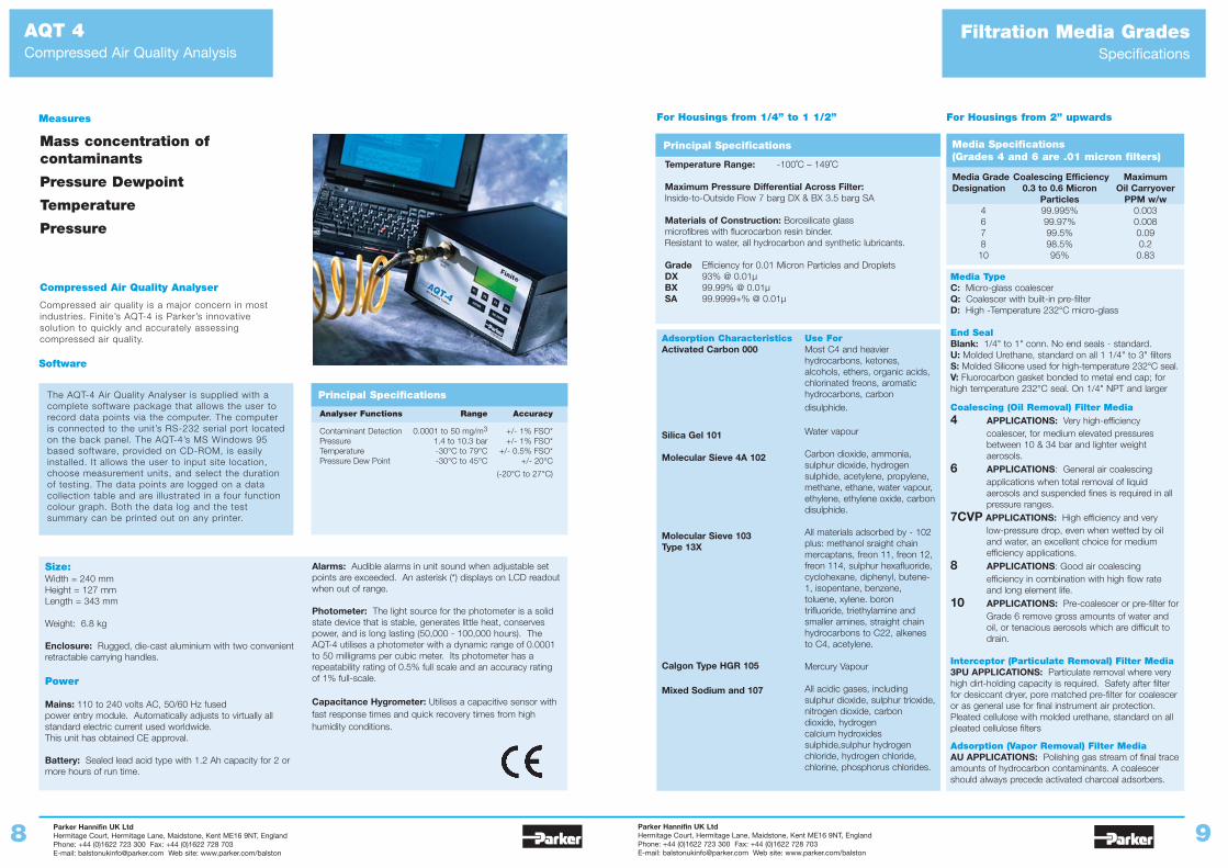
Compressed Air Quality Analyser
Compressed air quality is a major concern in mostindustries. Finite’s AQT-4 is Parker’s innovativesolution to quickly and accurately assessingcompressed air quality.
Software
The AQT-4 Air Quality Analyser is supplied with acomplete software package that allows the user torecord data points via the computer. The computeris connected to the unit’s RS-232 serial port locatedon the back panel. The AQT-4’s MS Windows 95based software, provided on CD-ROM, is easilyinstalled. It allows the user to input site location,choose measurement units, and select the durationof testing. The data points are logged on a datacollection table and are illustrated in a four functioncolour graph. Both the data log and the testsummary can be printed out on any printer.
Measures
Size:Width = 240 mmHeight = 127 mmLength = 343 mm
Weight: 6.8 kg
Enclosure: Rugged, die-cast aluminium with two convenientretractable carrying handles.
Power
Mains: 110 to 240 volts AC, 50/60 Hz fused power entry module. Automatically adjusts to virtually allstandard electric current used worldwide. This unit has obtained CE approval.
Battery: Sealed lead acid type with 1.2 Ah capacity for 2 ormore hours of run time.
Alarms: Audible alarms in unit sound when adjustable setpoints are exceeded. An asterisk (*) displays on LCD readoutwhen out of range.
Photometer: The light source for the photometer is a solidstate device that is stable, generates little heat, conservespower, and is long lasting (50,000 - 100,000 hours). TheAQT-4 utilises a photometer with a dynamic range of 0.0001to 50 milligrams per cubic meter. Its photometer has arepeatability rating of 0.5% full scale and an accuracy ratingof 1% full-scale.
Capacitance Hygrometer: Utilises a capacitive sensor withfast response times and quick recovery times from highhumidity conditions.
Principal Specifications
Analyser Functions Range Accuracy
Contaminant Detection 0.0001 to 50 mg/m3 +/- 1% FSO*Pressure 1.4 to 10.3 bar +/- 1% FSO*Temperature -30°C to 79°C +/- 0.5% FSO* Pressure Dew Point -30°C to 45°C +/- 20°C
(-20°C to 27°C)
Principal Specifications
Temperature Range: -100˚C – 149˚C
Maximum Pressure Differential Across Filter:Inside-to-Outside Flow 7 barg DX & BX 3.5 barg SA
Materials of Construction: Borosilicate glass microfibres with fluorocarbon resin binder. Resistant to water, all hydrocarbon and synthetic lubricants.
Grade Efficiency for 0.01 Micron Particles and DropletsDX 93% @ 0.01µBX 99.99% @ 0.01µSA 99.9999+% @ 0.01µ
For Housings from 1/4” to 1 1/2”
Media Grade Coalescing Efficiency MaximumDesignation 0.3 to 0.6 Micron Oil Carryover
Particles PPM w/w4 99.995% 0.0036 99.97% 0.0087 99.5% 0.098 98.5% 0.210 95% 0.83
Media TypeC: Micro-glass coalescerQ: Coalescer with built-in pre-filterD: High -Temperature 232°C micro-glass
End SealBlank: 1/4" to 1" conn. No end seals - standard.U: Molded Urethane, standard on all 1 1/4" to 3" filtersS: Molded Silicone used for high-temperature 232°C seal.V: Fluorocarbon gasket bonded to metal end cap; forhigh temperature 232°C seal. On 1/4" NPT and larger
Coalescing (Oil Removal) Filter Media4 APPLICATIONS: Very high-efficiency
coalescer, for medium elevated pressures between 10 & 34 bar and lighter weight aerosols.
6 APPLICATIONS: General air coalescing applications when total removal of liquid aerosols and suspended fines is required in all pressure ranges.
7CVP APPLICATIONS: High efficiency and very low-pressure drop, even when wetted by oil and water, an excellent choice for medium efficiency applications.
8 APPLICATIONS: Good air coalescing efficiency in combination with high flow rate and long element life.
10 APPLICATIONS: Pre-coalescer or pre-filter forGrade 6 remove gross amounts of water and oil, or tenacious aerosols which are difficult to drain.
Interceptor (Particulate Removal) Filter Media3PU APPLICATIONS: Particulate removal where veryhigh dirt-holding capacity is required. Safety after filterfor desiccant dryer, pore matched pre-filter for coalesceror as general use for final instrument air protection.Pleated cellulose with molded urethane, standard on allpleated cellulose filters
Adsorption (Vapor Removal) Filter MediaAU APPLICATIONS: Polishing gas stream of final traceamounts of hydrocarbon contaminants. A coalescershould always precede activated charcoal adsorbers.
Media Specifications (Grades 4 and 6 are .01 micron filters)
For Housings from 2” upwards
Parker Hannifin UK LtdHermitage Court, Hermitage Lane, Maidstone, Kent ME16 9NT, EnglandPhone: +44 (0)1622 723 300 Fax: +44 (0)1622 728 703E-mail: [email protected] Web site: www.parker.com/balston
Parker Hannifin UK LtdHermitage Court, Hermitage Lane, Maidstone, Kent ME16 9NT, EnglandPhone: +44 (0)1622 723 300 Fax: +44 (0)1622 728 703E-mail: [email protected] Web site: www.parker.com/balston
10 11
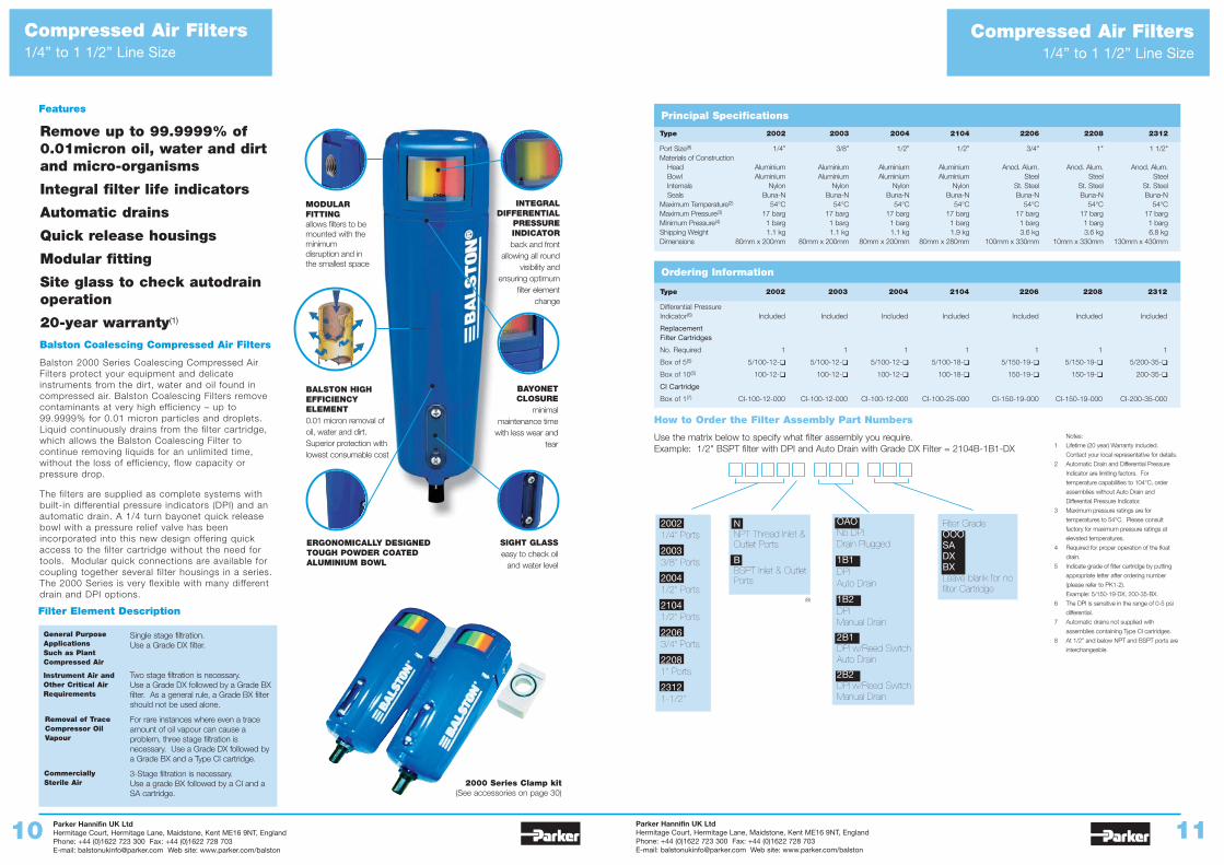
Remove up to 99.9999% of0.01micron oil, water and dirtand micro-organisms
Integral filter life indicators
Automatic drains
Quick release housings
Modular fitting
Site glass to check autodrainoperation
20-year warranty(1)
Balston Coalescing Compressed Air Filters
Balston 2000 Series Coalescing Compressed AirFilters protect your equipment and delicateinstruments from the dirt, water and oil found incompressed air. Balston Coalescing Filters removecontaminants at very high efficiency – up to99.9999% for 0.01 micron particles and droplets.Liquid continuously drains from the filter cartridge,which allows the Balston Coalescing Filter tocontinue removing liquids for an unlimited time,without the loss of efficiency, flow capacity orpressure drop.
The filters are supplied as complete systems withbuilt-in differential pressure indicators (DPI) and anautomatic drain. A 1/4 turn bayonet quick releasebowl with a pressure relief valve has beenincorporated into this new design offering quickaccess to the filter cartridge without the need fortools. Modular quick connections are available forcoupling together several filter housings in a series.The 2000 Series is very flexible with many differentdrain and DPI options.
INTEGRALDIFFERENTIAL
PRESSUREINDICATORback and front
allowing all roundvisibility and
ensuring optimumfilter element
change
SIGHT GLASSeasy to check oil
and water level
BAYONETCLOSURE
minimalmaintenance time
with less wear andtear
MODULARFITTINGallows filters to bemounted with theminimumdisruption and inthe smallest space
ERGONOMICALLY DESIGNEDTOUGH POWDER COATEDALUMINIUM BOWL
BALSTON HIGHEFFICIENCYELEMENT0.01 micron removal ofoil, water and dirt.Superior protection withlowest consumable cost
Filter Element Description
Single stage filtration. Use a Grade DX filter.
Two stage filtration is necessary. Use a Grade DX followed by a Grade BXfilter. As a general rule, a Grade BX filtershould not be used alone.
For rare instances where even a traceamount of oil vapour can cause aproblem, three stage filtration isnecessary. Use a Grade DX followed bya Grade BX and a Type CI cartridge.
3-Stage filtration is necessary. Use a grade BX followed by a CI and aSA cartridge.
General PurposeApplications Such as PlantCompressed Air
Removal of TraceCompressor OilVapour
Instrument Air andOther Critical AirRequirements
Compressed Air Filters1/4” to 1 1/2” Line Size
Features
Ordering Information
Type 2002 2003 2004 2104 2206 2208 2312
Differential Pressure Indicator(6) Included Included Included Included Included Included Included
Replacement Filter Cartridges
No. Required 1 1 1 1 1 1 1
Box of 5(5) 5/100-12-❑ 5/100-12-❑ 5/100-12-❑ 5/100-18-❑ 5/150-19-❑ 5/150-19-❑ 5/200-35-❑
Box of 10(5) 100-12-❑ 100-12-❑ 100-12-❑ 100-18-❑ 150-19-❑ 150-19-❑ 200-35-❑
CI Cartridge
Box of 1(7) CI-100-12-000 CI-100-12-000 CI-100-12-000 CI-100-25-000 CI-150-19-000 CI-150-19-000 CI-200-35-000
Notes:
1 Lifetime (20 year) Warranty included.
Contact your local representative for details.
2 Automatic Drain and Differential Pressure
Indicator are limiting factors. For
temperature capabilities to 104°C, order
assemblies without Auto Drain and
Differential Pressure Indicator.
3 Maximum pressure ratings are for
temperatures to 54°C. Please consult
factory for maximum pressure ratings at
elevated temperatures.
4 Required for proper operation of the float
drain.
5 Indicate grade of filter cartridge by putting
appropriate letter after ordering number
(please refer to PK1-2).
Example: 5/150-19-DX, 200-35-BX.
6 The DPI is sensitive in the range of 0-5 psi
differential.
7 Automatic drains not supplied with
assemblies containing Type CI cartridges.
8 At 1/2” and below NPT and BSPT ports are
interchangeable.
Principal Specifications
Type 2002 2003 2004 2104 2206 2208 2312
Port Size(8) 1/4” 3/8” 1/2” 1/2” 3/4" 1" 1 1/2"Materials of Construction
Head Aluminium Aluminium Aluminium Aluminium Anod. Alum. Anod. Alum. Anod. Alum.Bowl Aluminium Aluminium Aluminium Aluminium Steel Steel SteelInternals Nylon Nylon Nylon Nylon St. Steel St. Steel St. SteelSeals Buna-N Buna-N Buna-N Buna-N Buna-N Buna-N Buna-N
Maximum Temperature(2) 54°C 54°C 54°C 54°C 54°C 54°C 54°CMaximum Pressure(3) 17 barg 17 barg 17 barg 17 barg 17 barg 17 barg 17 barg Minimum Pressure(4) 1 barg 1 barg 1 barg 1 barg 1 barg 1 barg 1 bargShipping Weight 1.1 kg 1.1 kg 1.1 kg 1.9 kg 3.6 kg 3.6 kg 6.8 kgDimensions 80mm x 200mm 80mm x 200mm 80mm x 200mm 80mm x 280mm 100mm x 330mm 10mm x 330mm 130mm x 430mm
How to Order the Filter Assembly Part Numbers
Use the matrix below to specify what filter assembly you require. Example: 1/2" BSPT filter with DPI and Auto Drain with Grade DX Filter = 2104B-1B1-DX
OAONo DPIDrain Plugged
1B1DPIAuto Drain
1B2DPIManual Drain
2B1DPI w/Reed SwitchAuto Drain
2B2DPI w/Reed SwitchManual Drain
Filter GradeOOOSADXBXLeave blank for nofilter Cartridge
20021/4" Ports
20033/8" Ports
20041/2" Ports
21041/2" Ports
22063/4" Ports
22081" Ports
23121-1/2"
NNPT Thread Inlet &Outlet Ports
BBSPT Inlet & OutletPorts
(8)
Compressed Air Filters1/4” to 1 1/2” Line Size
CommerciallySterile Air 2000 Series Clamp kit
(See accessories on page 30)
Parker Hannifin UK LtdHermitage Court, Hermitage Lane, Maidstone, Kent ME16 9NT, EnglandPhone: +44 (0)1622 723 300 Fax: +44 (0)1622 728 703E-mail: [email protected] Web site: www.parker.com/balston
Parker Hannifin UK LtdHermitage Court, Hermitage Lane, Maidstone, Kent ME16 9NT, EnglandPhone: +44 (0)1622 723 300 Fax: +44 (0)1622 728 703E-mail: [email protected] Web site: www.parker.com/balston
12 13
Compressed Air Filters2” to 3” Line Size
Compressed Air Filters2” to 3” Line Size
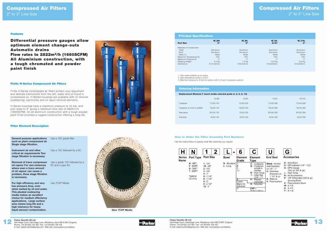
Features
Differential pressure gauges allowoptimum element change-outsAutomatic drainsFlow rates to 2822m3/h (1660SCFM)All Aluminium construction, witha tough chromated and powderpaint finish
Finite H-Series Compressed Air Filters
Finite H-Series compressed air filters protect your equipmentand delicate instruments form the dirt, water and oil found incompressed air. H-Series housings are available with oil removal(coalescing), particulate and oil vapor removal elements.
H-Series housings have a maximum pressure to 34 bar, andport sizes to 3" giving a maximum flow rate of 2822m3/h(1660SCFM). An all aluminum construction with a tough powderpaint finish provides a rugged construction offering a long life.
Filter Element Description
1. Viton seals available as an option2. High temperature option to 232˚C3. Maximum pressure is 34 bar for options with G, N and V accessory options
Principal Specifications
H[ ]8S H[ ]8L H[ ]0L H[ ]12LPort Size 2" 2" 21/2" 3"
Materials of ConstructionHead Aluminium Aluminium Aluminium AluminiumBowl Aluminium Aluminium Aluminium AluminiumSeals (1) Nitrile Nitrile Nitrile Nitrile
Maximum Temperature (2) 79˚C 79˚C 79˚C 79˚CMaximum Pressure (3) 17 17 17 17Shipping Weight 6.4 Kg 7.3 Kg 15.9 Kg 15.9 KgDimensions 617x152mm 745x152mm 914x203mm 914x203mm
Ordering Information
Replacement Element (* insert media selected grade 2, 4, 6, 8, 10)
H[ ]8S H[ ]8L H[ ]0L H[ ]12L
Coalescer *CU25-187 *CU25-235 *CU35-280 *CU35-280
Coalescer w/ built-in prefilter *QU25-187 *QU25-235 *QU35-280 *QU35-280
Interceptor 3PU25-187 PU25-235 3PU35-280 3PU35-280
Adsorber AU25-187 AU25-235 AU35-280 AU35-280
How to Order the Filter Assembly Part Numbers
Use the matrix below to specify what filter assembly you require.
General purpose applicationssuch as plant compressed airSingle stage filtration.
Instrument air and othercritical air requirements Twostage filtration is necessary.
Removal of trace compressoroil vapour For rare instanceswhere even a trace amountof oil vapour can cause aproblem, three stage filtrationis necessary.
For high efficiency and verylow pressure drop, evenwhen wetted by oil and water.This pleated coalescingmedia makes an excellentchoice for medium effeciencyapplications. Large surfacearea means long life and ahigh tolerance for heavyliquid aerosol contamination.
Use a 10C grade filter
Use a 10C followed by a 6C
Use a grade 10C followed by a6C and a type AU
Use 7CVP Media
New 7CVP Media
Parker Hannifin UK LtdHermitage Court, Hermitage Lane, Maidstone, Kent ME16 9NT, EnglandPhone: +44 (0)1622 723 300 Fax: +44 (0)1622 728 703E-mail: [email protected] Web site: www.parker.com/balston
Parker Hannifin UK LtdHermitage Court, Hermitage Lane, Maidstone, Kent ME16 9NT, EnglandPhone: +44 (0)1622 723 300 Fax: +44 (0)1622 728 703E-mail: [email protected] Web site: www.parker.com/balston
14 15
Compressed Air Filters3” to 16” Line Size
Compressed Air FiltersMiniature Point of Use Filter
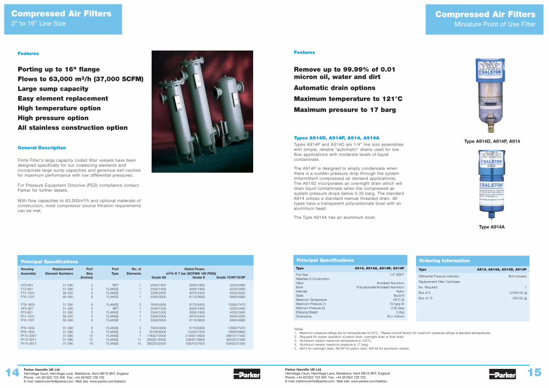
Remove up to 99.99% of 0.01micron oil, water and dirt
Automatic drain options
Maximum temperature to 121°C
Maximum pressure to 17 barg
Types A914D, A914P, A914, A914ATypes A914P and A914D are 1/4" line size assemblieswith simple, reliable "automatic" drains used for lowflow applications with moderate levels of liquidcontaminate.
The A914P is designed to empty condensate whenthere is a sudden pressure drop through the system(intermittent compressed air demand applications).The A914D incorporates an overnight drain which willdrain liquid contaminate when the compressed airsystem pressure drops below 0.35 barg. The standardA914 utilizes a standard manual threaded drain. Alltypes have a transparent polycarbonate bowl with analuminium head.
The Type A914A has an aluminium bowl.
Ordering Information
Type A914, A914A, A914D, A914P
Differential Pressure Indicator Not Included
Replacement Filter Cartridges
No. Required 1
Box of 5 5/050-05-❑
Box of 10 050-05-❑
Principal Specifications
Type A914, A914A, A914D, A914P
Port Size 1/4" BSPTMaterials of ConstructionHead Anodised AluminiumBowl Polycarbonate/Anodised AluminiumInternals NylonSeals Buna-NMaximum Temperature 49°C (3)Maximum Pressure (1) 10 barg (4)Minimum Pressure (2) 0.35 bargShipping Weight 0.2kgDimensions 40 x 100mm
Features
Notes:1. Maximum pressure ratings are for temperatures to 54°C. Please consult factory for maximum pressure ratings at elevated temperatures.2. Required for proper operation of piston drain, overnight drain or float drain.3. Aluminium version maximum temperature is 120°C.4. Aluminium version maximum pressure is 17 barg.5. A914 for overnight drain, A914P for piston drain, A914A for aluminium version.
Type A914D, A914P, A914
Type A914A
Features
Porting up to 16" flange
Flows to 63,000 m3/h (37,000 SCFM)
Large sump capacity
Easy element replacement
High temperature option
High pressure option
All stainless construction option
General Description
Finite Filter's large capacity coded filter vessels have beendesigned specifically for our coalescing elements andincorporate large sump capacities and generous exit cavitiesfor maximum performance with low differential pressures.
For Pressure Equipment Directive (PED) compliance contactParker for further details.
With flow capacities to 63,000m3/h and optional materials ofconstruction, most compressor source filtration requirementscan be met.
Principal SpecificationsHousing Replacement Port Port No. of Rated Flows:Assembly Element Numbers Size Type Elements m3/h @ 7 bar (SCFM@ 100 PSIG)
(Inches) Grade 6A Grade 8 Grade 7CVP/10/3P
HT3-801 51-280 3 NPT 1 2540/1500 3050/1800 4230/2490FT3-801 51-280 3 FLANGE 1 2540/1500 3050/1800 4230/2490FT4-1201 85-250 4 FLANGE 1 3390/2000 4070/2400 5640/3320FT6-1201 85-360 6 FLANGE 1 5090/3000 6110/3600 8460/4980
FT6-1603 51-280 6 FLANGE 3 7640/4500 9170/5400 12690/7470HF3-801 51-280 3 NPT 1 2540/1500 3050/1800 4230/2490FF3-801 51-280 3 FLANGE 1 2540/1500 3050/1800 4230/2490FF4-1201 85-250 4 FLANGE 1 3390/2000 4070/2400 5640/3320FF6-1201 85-360 6 FLANGE 1 5090/3000 6110/3600 8460/4980
FF6-1603 51-280 6 FLANGE 3 7640/4500 9170/5400 12690/7470FF8-1804 51-280 8 FLANGE 4 10190/6000 12230/7200 16920/9960FF10-2207 51-280 10 FLANGE 7 17830/10500 21400/12600 29610/17430FF12-3011 51-280 12 FLANGE 11 28030/16500 33640/19800 46530/27390FF16-3615 51-280 16 FLANGE 15 38220/22500 45870/27000 63450/37350
Parker Hannifin UK LtdHermitage Court, Hermitage Lane, Maidstone, Kent ME16 9NT, EnglandPhone: +44 (0)1622 723 300 Fax: +44 (0)1622 728 703E-mail: [email protected] Web site: www.parker.com/balston
Parker Hannifin UK LtdHermitage Court, Hermitage Lane, Maidstone, Kent ME16 9NT, EnglandPhone: +44 (0)1622 723 300 Fax: +44 (0)1622 728 703E-mail: [email protected] Web site: www.parker.com/balston
16 17
Filter SilencersExhaust Coalescers and Silencers
Medium, High Pressure andStainless Steel Filters
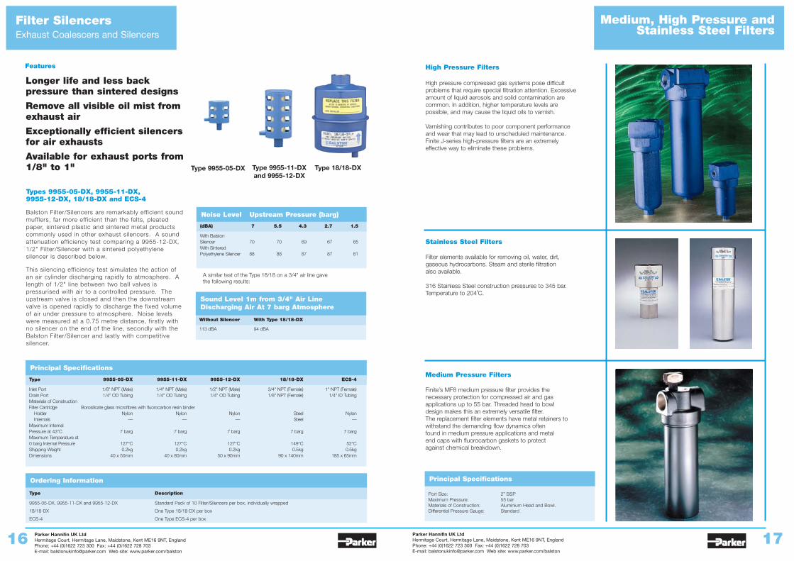
Longer life and less backpressure than sintered designs
Remove all visible oil mist fromexhaust air
Exceptionally efficient silencersfor air exhausts
Available for exhaust ports from1/8" to 1"
Types 9955-05-DX, 9955-11-DX, 9955-12-DX, 18/18-DX and ECS-4
Balston Filter/Silencers are remarkably efficient soundmufflers, far more efficient than the felts, pleatedpaper, sintered plastic and sintered metal productscommonly used in other exhaust silencers. A soundattenuation efficiency test comparing a 9955-12-DX,1/2" Filter/Silencer with a sintered polyethylenesilencer is described below.
This silencing efficiency test simulates the action ofan air cylinder discharging rapidly to atmosphere. Alength of 1/2" line between two ball valves ispressurised with air to a controlled pressure. Theupstream valve is closed and then the downstreamvalve is opened rapidly to discharge the fixed volumeof air under pressure to atmosphere. Noise levelswere measured at a 0.75 metre distance, firstly withno silencer on the end of the line, secondly with theBalston Filter/Silencer and lastly with competitivesilencer.
Features
Type 9955-05-DX Type 9955-11-DXand 9955-12-DX
Type 18/18-DX
Noise Level Upstream Pressure (barg)
(dBA) 7 5.5 4.3 2.7 1.5
With BalstonSilencer 70 70 69 67 65With SinteredPolyethylene Silencer 88 88 87 87 81
Sound Level 1m from 3/4" Air LineDischarging Air At 7 barg Atmosphere
Without Silencer With Type 18/18-DX
113 dBA 94 dBA
A similar test of the Type 18/18 on a 3/4" air line gavethe following results:
Ordering Information
Type Description
9955-05-DX, 9955-11-DX and 9955-12-DX Standard Pack of 10 Filter/Silencers per box, individually wrapped
18/18-DX One Type 18/18-DX per box
ECS-4 One Type ECS-4 per box
Principal Specifications
Type 9955-05-DX 9955-11-DX 9955-12-DX 18/18-DX ECS-4
Inlet Port 1/8" NPT (Male) 1/4" NPT (Male) 1/2" NPT (Male) 3/4" NPT (Female) 1" NPT (Female)Drain Port 1/4" OD Tubing 1/4" OD Tubing 1/4" OD Tubing 1/8" NPT (Female) 1/4" ID TubingMaterials of ConstructionFilter Cartridge Borosilicate glass microfibres with fluorocarbon resin binder
Holder Nylon Nylon Nylon Steel NylonInternals — — — Steel —
Maximum Internal Pressure at 43°C 7 barg 7 barg 7 barg 7 barg 7 bargMaximum Temperature at0 barg Internal Pressure 127°C 127°C 127°C 149°C 52°CShipping Weight 0.2kg 0.2kg 0.2kg 0.5kg 0.5kgDimensions 40 x 50mm 40 x 80mm 50 x 90mm 90 x 140mm 185 x 65mm
Medium Pressure Filters
Finite’s MF8 medium pressure filter provides thenecessary protection for compressed air and gasapplications up to 55 bar. Threaded head to bowldesign makes this an extremely versatile filter. The replacement filter elements have metal retainers towithstand the demanding flow dynamics oftenfound in medium pressure applications and metalend caps with fluorocarbon gaskets to protectagainst chemical breakdown.
Principal Specifications
Port Size: 2” BSPMaximum Pressure: 55 barMaterials of Construction: Aluminium Head and Bowl.Differential Pressure Gauge: Standard
Stainless Steel Filters
Filter elements available for removing oil, water, dirt,gaseous hydrocarbons. Steam and sterile filtration also available.
316 Stainless Steel construction pressures to 345 bar.Temperature to 204˚C.
High Pressure Filters
High pressure compressed gas systems pose difficultproblems that require special filtration attention. Excessiveamount of liquid aerosols and solid contamination arecommon. In addition, higher temperature levels arepossible, and may cause the liquid oils to varnish.
Varnishing contributes to poor component performanceand wear that may lead to unscheduled maintenance.Finite J-series high-pressure filters are an extremelyeffective way to eliminate these problems.
m3/h
Parker Hannifin UK LtdHermitage Court, Hermitage Lane, Maidstone, Kent ME16 9NT, EnglandPhone: +44 (0)1622 723 300 Fax: +44 (0)1622 728 703E-mail: [email protected] Web site: www.parker.com/balston
Parker Hannifin UK LtdHermitage Court, Hermitage Lane, Maidstone, Kent ME16 9NT, EnglandPhone: +44 (0)1622 723 300 Fax: +44 (0)1622 728 703E-mail: [email protected] Web site: www.parker.com/balston
18 19
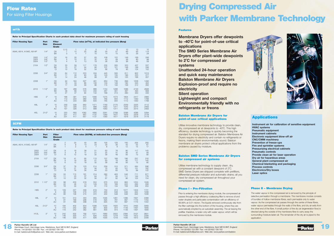
Drying Compressed Air with Parker Membrane Technology
Phase I – Pre-Filtration
Prior to entering the membrane drying module, the compressed airpasses through a high efficiency coalescing filter to remove oil andwater droplets and particulate contamination with an efficiency of99.99% at 0.01 micron. The liquids removed continuously drip fromthe filter cartridge into the bottom of the housing, where they areautomatically emptied by an autodrain assembly. The air leaving theprefilter, therefore, is laden only with water vapour, which will beremoved by the membrane module.
Phase II – Membrane Drying
The water vapour in the compressed air is removed by the principle ofselective permeation through a membrane. The membrane module consistsof bundles of hollow membrane fibres, each permeable only to watervapour. As the compressed air passes through the centre of these fibres,water vapour permeates through the walls of the fibre, and dry air exits fromthe other end of the fibre. A small portion of the dry air (regeneration flow) isdirected along the outside of the membrane fibre to carry away thesurrounding moisture-laden air. The remainder of the dry air is piped to theapplication.
Features
Membrane Dryers offer dewpointsto -40˚C for point-of-use criticalapplicationsThe SMD Series Membrane AirDryers offer plant-wide dewpointsto 2˚C for compressed airsystemsUnattended 24-hour operationand quick easy maintenanceBalston Membrane Air DryersExplosion-proof and require noelectricitySilent operationLightweight and compactEnvironmentally friendly with norefrigerants or freons
Balston Membrane Air Dryers for point-of-use critical applications
Utilise innovative membrane technology to provide clean,dry, compressed air at dewpoints to -40˚C. This highefficiency, durable technology is quickly becoming thestandard for drying compressed air. Balston Membrane AirDryers require no electricity and contain no refrigerants orfreons, making them environmentally sound. Balstonmembrane air dryers protect critical applications from theproblems caused by moisture.
Balston SMD Series Membrane Air Dryersfor compressed air systems
Utilise membrane technology to supply clean, dry,compressed air with a constant dewpoint of 2˚C. SMD Series Dryers are shipped complete with prefilters,differential pressure indicator and automatic drains; all youneed for clean, dry compressed air throughout yourcompressed air system.
Applications
Instrument air for calibration of sensitive equipmentHVAC systemsPneumatic equipmentInstrument cabinetsElectronic equipment blow-off airCNC/CMM machineryPrevention of freeze-upsFire and sprinkler systemsPressurizing electrical cabinetsPneumatic controlsProvide clean air for laser operationDry air for hazardous areasGeneral plant compressed airChemical blanketing and packagingProcess controlsElectronics/Dry boxesLaser optics
Flow RatesFor sizing Filter Housings
Refer to Principal Specification Charts in each product data sheet for maximum pressure rating of each housing
Filter Housing Type Port Filter Flow rates (m3/h), at indicated line pressure (Barg)Size Element
Grade0.15 1 3 5 7 8 10 13 15
A94A, A914, A194D, A914P 1/4" DX 7 12 25 38 50 57 69 93 114BX 3 4 7 10 14 15 18 26 29
2002 1/4" DX 16 30 57 83 109 122 149 199 2462003 3/8" BX 5 10 21 32 43 49 59 80 992004 1/2" CI 4 6 13 19 26 29 36 48 59
2104 1/2" DX 33 58 117 176 235 265 323 437 537BX 15 27 54 80 107 121 148 199 246CI 10 18 32 54 66 78 95 124 152
2206 3/4" DX 64 112 223 334 445 500 611 822 1013BX 17 30 60 90 120 135 166 223 277CI 14 24 46 68 91 103 125 168 207
2208 1" DX 94 164 327 491 654 736 899 1208 1490BX 19 33 66 100 133 149 182 245 302CI 17 29 58 86 115 130 158 212 262
2312 1 1/2" DX 167 289 578 866 1154 1298 1586 2130 2626BX 38 66 133 200 267 301 367 493 608CI 27 47 94 142 189 213 260 350 430
H8S 2" 10 188 391 616 1066 1275 1573 1854 2417 29806 113 234 369 640 765 944 1112 1450 1788
AU 113 234 369 640 765 944 1112 1450 1788
H8L 2" 10 259 539 850 1471 1760 2170 2559 3335 41126 157 326 513 888 1063 1311 1545 2014 2483
AU 157 326 513 888 1063 1311 1545 2014 2483
H0L 21/2" 10 333 693 1092 1890 2261 2789 3288 4286 52846 201 417 657 1137 1360 1677 1978 2578 3178
AU 201 417 657 1137 1360 1677 1978 2578 3178
SCFM
Refer to Principal Specification Charts in each product data sheet for maximum pressure rating of each housing
Filter Housing Type Port Filter Flow rates (SCFM), at indicated line pressure (Barg)Size Element
Grade
2 20 40 80 100 125 150 200 250A94A, A914, A194D, A914P 1/4" DX 4 9 13 24 29 36 43 55 67
BX 1 2 4 7 8 9 12 15 17
2002 1/4" DX 9 19 39 51 63 76 90 117 1452003 3/8" BX 3 8 11 21 25 31 36 47 582004 1/2" CI 6 12 19 32 39 48 56 73 90
2104 1/2" DX 19 41 65 113 137 166 196 257 316BX 9 19 30 51 63 76 90 117 145CI 6 12 19 32 39 48 56 73 90
2206 3/4" DX 37 78 123 214 259 315 371 484 596BX 10 21 34 56 70 85 101 131 162CI 8 16 26 44 53 65 76 99 122
2208 1" DX 55 115 181 314 380 463 546 711 877BX 11 23 37 64 77 94 111 144 178CI 10 20 32 56 67 82 96 125 154
2312 1 1/2" DX 98 203 319 554 670 816 963 1254 1546BX 22 46 74 129 155 189 223 290 358CI 16 33 52 91 110 134 158 206 253
H8S 2" 10 109 227 358 619 750 913 1077 1404 17316 66 136 215 372 450 548 646 842 1038
AU 66 136 215 372 450 548 646 842 1038
H8L 2" 10 151 313 494 855 1035 1261 1486 1937 23896 91 189 298 516 625 761 897 1170 1442
AU 91 189 298 516 625 761 897 1170 1442
H0L 21/2" 10 194 402 634 1098 1330 1620 1910 2490 30696 116 242 382 661 800 974 1149 1497 1846
AU 116 242 382 661 800 974 1149 1497 1846
H12L 3" 10 242 502 792 1371 1660 2022 2384 3107 38316 146 303 477 826 1000 1218 1436 1872 2308
AU 146 303 477 826 1000 1218 1436 1872 2308
Parker Hannifin UK LtdHermitage Court, Hermitage Lane, Maidstone, Kent ME16 9NT, EnglandPhone: +44 (0)1622 723 300 Fax: +44 (0)1622 728 703E-mail: [email protected] Web site: www.parker.com/balston
Parker Hannifin UK LtdHermitage Court, Hermitage Lane, Maidstone, Kent ME16 9NT, EnglandPhone: +44 (0)1622 723 300 Fax: +44 (0)1622 728 703E-mail: [email protected] Web site: www.parker.com/balston
20 21
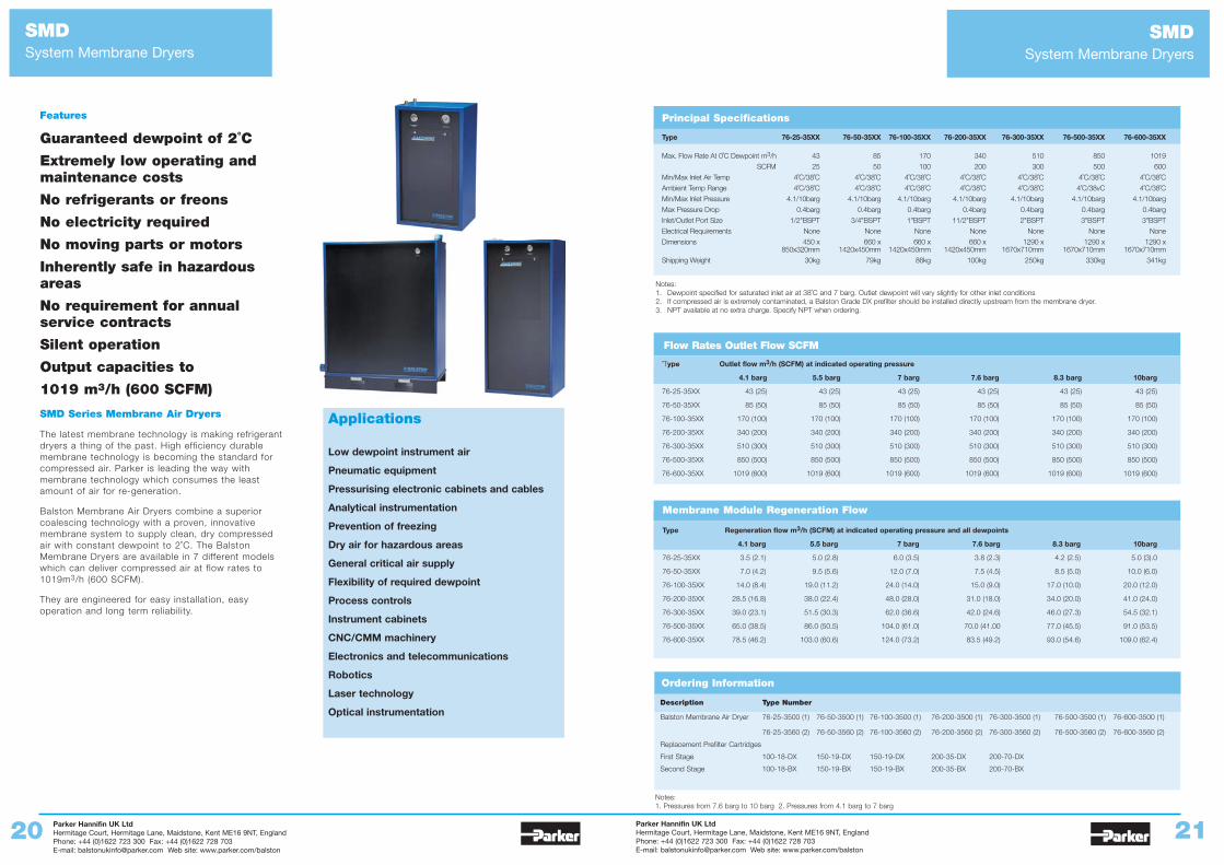
SMDSystem Membrane Dryers
SMDSystem Membrane Dryers
Guaranteed dewpoint of 2˚C
Extremely low operating andmaintenance costs
No refrigerants or freons
No electricity required
No moving parts or motors
Inherently safe in hazardousareas
No requirement for annualservice contracts
Silent operation
Output capacities to
1019 m3/h (600 SCFM)
SMD Series Membrane Air Dryers
The latest membrane technology is making refrigerantdryers a thing of the past. High efficiency durablemembrane technology is becoming the standard forcompressed air. Parker is leading the way withmembrane technology which consumes the leastamount of air for re-generation.
Balston Membrane Air Dryers combine a superiorcoalescing technology with a proven, innovativemembrane system to supply clean, dry compressedair with constant dewpoint to 2˚C. The BalstonMembrane Dryers are available in 7 different modelswhich can deliver compressed air at flow rates to1019m3/h (600 SCFM).
They are engineered for easy installation, easyoperation and long term reliability.
Applications
Low dewpoint instrument air
Pneumatic equipment
Pressurising electronic cabinets and cables
Analytical instrumentation
Prevention of freezing
Dry air for hazardous areas
General critical air supply
Flexibility of required dewpoint
Process controls
Instrument cabinets
CNC/CMM machinery
Electronics and telecommunications
Robotics
Laser technology
Optical instrumentation
Features
Notes: 1. Dewpoint specified for saturated inlet air at 38˚C and 7 barg. Outlet dewpoint will vary slightly for other inlet conditions2. If compressed air is extremely contaminated, a Balston Grade DX prefilter should be installed directly upstream from the membrane dryer.3. NPT available at no extra charge. Specify NPT when ordering.
Ordering Information
Description Type Number
Balston Membrane Air Dryer 76-25-3500 (1) 76-50-3500 (1) 76-100-3500 (1) 76-200-3500 (1) 76-300-3500 (1) 76-500-3500 (1) 76-600-3500 (1)
76-25-3560 (2) 76-50-3560 (2) 76-100-3560 (2) 76-200-3560 (2) 76-300-3560 (2) 76-500-3560 (2) 76-600-3560 (2)
Replacement Prefilter Cartridges
First Stage 100-18-DX 150-19-DX 150-19-DX 200-35-DX 200-70-DX
Second Stage 100-18-BX 150-19-BX 150-19-BX 200-35-BX 200-70-BX
Notes: 1. Pressures from 7.6 barg to 10 barg 2. Pressures from 4.1 barg to 7 barg
Flow Rates Outlet Flow SCFM
Type Regeneration flow m3/h (SCFM) at indicated operating pressure and all dewpoints
4.1 barg 5.5 barg 7 barg 7.6 barg 8.3 barg 10barg
76-25-35XX 3.5 (2.1) 5.0 (2.8) 6.0 (3.5) 3.8 (2.3) 4.2 (2.5) 5.0 (3).0
76-50-35XX 7.0 (4.2) 9.5 (5.6) 12.0 (7.0) 7.5 (4.5) 8.5 (5.0) 10.0 (6.0)
76-100-35XX 14.0 (8.4) 19.0 (11.2) 24.0 (14.0) 15.0 (9.0) 17.0 (10.0) 20.0 (12.0)
76-200-35XX 28.5 (16.8) 38.0 (22.4) 48.0 (28.0) 31.0 (18.0) 34.0 (20.0) 41.0 (24.0)
76-300-35XX 39.0 (23.1) 51.5 (30.3) 62.0 (36.6) 42.0 (24.6) 46.0 (27.3) 54.5 (32.1)
76-500-35XX 65.0 (38.5) 86.0 (50.5) 104.0 (61.0) 70.0 (41.00 77.0 (45.5) 91.0 (53.5)
76-600-35XX 78.5 (46.2) 103.0 (60.6) 124.0 (73.2) 83.5 (49.2) 93.0 (54.6) 109.0 (62.4)
Membrane Module Regeneration Flow
Principal Specifications
Type 76-25-35XX 76-50-35XX 76-100-35XX 76-200-35XX 76-300-35XX 76-500-35XX 76-600-35XX
Max. Flow Rate At 0˚C Dewpoint m3/h 43 85 170 340 510 850 1019
SCFM 25 50 100 200 300 500 600
Min/Max Inlet Air Temp 4˚C/38˚C 4˚C/38˚C 4˚C/38˚C 4˚C/38˚C 4˚C/38˚C 4˚C/38˚C 4˚C/38˚C
Ambient Temp Range 4˚C/38˚C 4˚C/38˚C 4˚C/38˚C 4˚C/38˚C 4˚C/38˚C 4˚C/38vC 4˚C/38˚C
Min/Max Inlet Pressure 4.1/10barg 4.1/10barg 4.1/10barg 4.1/10barg 4.1/10barg 4.1/10barg 4.1/10barg
Max Pressure Drop 0.4barg 0.4barg 0.4barg 0.4barg 0.4barg 0.4barg 0.4barg
Inlet/Outlet Port Size 1/2"BSPT 3/4"BSPT 1"BSPT 11/2"BSPT 2"BSPT 3"BSPT 3"BSPT
Electrical Requirements None None None None None None None
Dimensions 450 x 660 x 660 x 660 x 1290 x 1290 x 1290 x850x320mm 1420x450mm 1420x450mm 1420x450mm 1670x710mm 1670x710mm 1670x710mm
Shipping Weight 30kg 79kg 86kg 100kg 250kg 330kg 341kg
˚Type Outlet flow m3/h (SCFM) at indicated operating pressure
4.1 barg 5.5 barg 7 barg 7.6 barg 8.3 barg 10barg
76-25-35XX 43 (25) 43 (25) 43 (25) 43 (25) 43 (25) 43 (25)
76-50-35XX 85 (50) 85 (50) 85 (50) 85 (50) 85 (50) 85 (50)
76-100-35XX 170 (100) 170 (100) 170 (100) 170 (100) 170 (100) 170 (100)
76-200-35XX 340 (200) 340 (200) 340 (200) 340 (200) 340 (200) 340 (200)
76-300-35XX 510 (300) 510 (300) 510 (300) 510 (300) 510 (300) 510 (300)
76-500-35XX 850 (500) 850 (500) 850 (500) 850 (500) 850 (500) 850 (500)
76-600-35XX 1019 (600) 1019 (600) 1019 (600) 1019 (600) 1019 (600) 1019 (600)
Parker Hannifin UK LtdHermitage Court, Hermitage Lane, Maidstone, Kent ME16 9NT, EnglandPhone: +44 (0)1622 723 300 Fax: +44 (0)1622 728 703E-mail: [email protected] Web site: www.parker.com/balston
Parker Hannifin UK LtdHermitage Court, Hermitage Lane, Maidstone, Kent ME16 9NT, EnglandPhone: +44 (0)1622 723 300 Fax: +44 (0)1622 728 703E-mail: [email protected] Web site: www.parker.com/balston
22 23
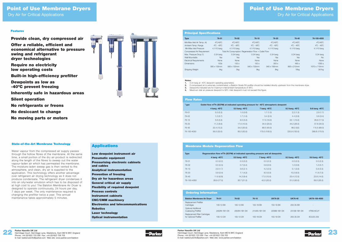
Point of Use Membrane DryersDry Air for Critical Applications
Provide clean, dry compressed air
Offer a reliable, efficient andeconomical alternative to pressureswing and refrigerant dryer technologies
Require no electricity low operating costs
Built-in high-efficiency prefilter
Dewpoints as low as -40ºC prevent freezing
Inherently safe in hazardous areas
Silent operation
No refrigerants or freons
No desiccant to change
No moving parts or motors
State-of-the-Art Membrane Technology
Water vapour from the compressed air supply passesthrough the hollow fibres of the membrane. At the sametime, a small portion of the dry air product is redirectedalong the length of the fibres to sweep out the watervapour-laden air which has permeated the membrane.The moisture-laden sweep gas is then vented to theatmosphere, and clean, dry air is supplied to theapplication. This technology offers another advantageover refrigerant air drying technology as it does notproduce condensate. The refrigerant dryer condenses itinto an oily/water emulsion which has to be disposed ofat high cost to you! The Balston Membrane Air Dryer isdesigned to operate continuously, 24 hours per day, 7 days per week. The only maintenance required ischanging the prefilter twice a year. This annualmaintenance takes approximately 5 minutes.
Applications
Low dewpoint instrument air
Pneumatic equipment
Pressurising electronic cabinets and cables
Analytical instrumentation
Prevention of freezing
Dry air for hazardous areas
General critical air supply
Flexibility of required dewpoint
Process controls
Instrument cabinets
CNC/CMM machinery
Electronics and telecommunications
Robotics
Laser technology
Optical instrumentation
Features
Ordering Information
Balston Membrane Air Dryer 76-01 76-02 76-10 UK76-20 UK76-40 UK76-100-4050
Replacement PrefilterCartridges 100-12-BX 100-12-BX 100-18-BX 150-19-BX 200-35-BX -
Optional AdditionalCoalescing Prefilter 2002N-1B1-DX 2002N-1B1-DX 2104N-1B1-DX 2208B-1B1-DX 2312B-1B1-DX HT8S-6CUY
Replacement Filter Cartridgesfor Optional Prefilter 100-12-DX 100-12-DX 100-18-DX 150-19-DX 200-35-DX 6CU25-235
Point of Use Membrane DryersDry Air for Critical Applications
Flow Rates
Type Regeneration flow m3/h (SCFM) at indicated operating pressure and all dewpoints
4 barg -40˚C 5.5 barg -40˚C 7 barg -40˚C 8.3 barg -40˚C 9.6 barg -40˚C
76-01 0.3 (0.2) 0.3 (0.2) 0.5 (0.3) 0.5 (0.3) 0.5 (0.3)
76-02 0.5 (0.3) 0.7 (0.4) 0.8 (0.5) 1.0 (0.6) 1.2 (0.7)
76-10 2.9 (1.7) 3.6 (2.1) 4.2 (2.5) 5.1 (3.0) 5.9 (3.5)
76-20 5.8 (3.4) 7.1 (4.2) 8.5 (5.0) 10.2 (6.0) 11.9 (7.0)
76-40 11.6 (6.8) 14.3 (8.4) 17.0 (10.0) 20.4 (12.0) 23.8 (14.0)
76-100-4050 28.9 (17.0) 35.7 (21.0) 42.5 (25.0) 51.0 (30.0) 59.5 (35.0)
Membrane Module Regeneration Flow
Principal Specifications
Type 76-01 76-02 76-10 76-20 76-40 76-100-4050
Min/Max Inlet Air Temp. (4) 4˚C/49˚C 4˚C/49˚C 4˚C/49˚C 4˚C/49˚C 4˚C/49˚C 4˚C/49˚C
Ambient Temp. Range 4˚C - 49˚C 4˚C - 49˚C 4˚C - 49˚C 4˚C - 49˚C 4˚C - 49˚C 4˚C - 49˚C
Min/Max Inlet Pressure 4.1/10 barg 4.1/10 barg 4.1/10 barg 4.1/10 barg 4.1/10 barg 4.1/10 barg
Compressed Air Requirement Total Air Consumption: Regeneration Flow + Outlet Flow
Max. Pressure Drop (1) 0.34 barg 0.34 barg 0.34 barg 0.34 barg 0.34 barg 0.34 barg
Wall Mountable Yes Yes Yes Yes Yes No
Electrical Requirements None None None None None None
Dimensions 150x 150 x 150 x 300 x 480 x 1290 x
580 x 130mm 580 x 130mm 940 x 130mm 940 x 180mm 990 x 210mm 1670 x 710mm
Shipping Weight 4kg 5kg 9kg 9kg 16kg 341kg
˚Type Outlet flow m3/h (SCFM) at indicated operating pressure for -40˚C atmospheric dewpoint
4 barg -40˚C 5.5 barg -40˚C 7 barg -40˚C 8.3 barg -40˚C 9.6 barg -40˚C
76-01 0.5 (0.3) 1.0 (0.6) 1.7 (1.0) 2.2 (1.3) 2.9 (1.7)
76-02 1.2 (0.7) 1.7 (1.0) 3.4 (2.0) 4.4 (2.6) 5.8 (3.4)
76-10 5.6 (3.3) 8.5 (5.0) 17.0 (10.0) 22.1 (13.0) 28.9 (17.0)
76-20 11.2 (6.6) 17.0 (10.0) 34.0 (20.0) 44.2 (26.0) 57.8 (34.0)
76-40 22.4 (13.2) 34.0 (20.0) 68.0 (40.0) 88.3 (52) 115.5 (68.0)
76-100-4050 56.0 (33.0) 85.0 (50.0) 170.0 (100.0) 220.9 (130.0) 288.8 (170.0)
Notes:1. 0.34 barg at -40˚C dewpoint operating parameters.2. If compressed air is extremely contaminated, a Balston Grade DX prefilter should be installed directly upstream from the membrane dryer.3. Dewpoints indicated are for maximum inlet/ambient temperature of 38˚C.4. Maximum inlet air pressure dewpoint is 38˚C. Inlet dewpoint must not exceed this figure.
Parker Hannifin UK LtdHermitage Court, Hermitage Lane, Maidstone, Kent ME16 9NT, EnglandPhone: +44 (0)1622 723 300 Fax: +44 (0)1622 728 703E-mail: [email protected] Web site: www.parker.com/balston
Parker Hannifin UK LtdHermitage Court, Hermitage Lane, Maidstone, Kent ME16 9NT, EnglandPhone: +44 (0)1622 723 300 Fax: +44 (0)1622 728 703E-mail: [email protected] Web site: www.parker.com/balston
24 25
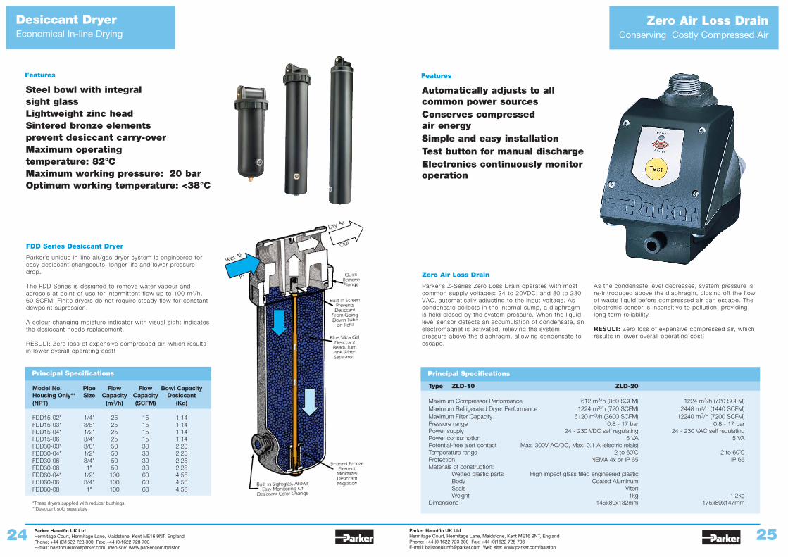
Desiccant DryerEconomical In-line Drying
Zero Air Loss DrainConserving Costly Compressed Air
Automatically adjusts to allcommon power sourcesConserves compressed air energySimple and easy installationTest button for manual dischargeElectronics continuously monitoroperation
Zero Air Loss Drain
Parker’s Z-Series Zero Loss Drain operates with mostcommon supply voltages: 24 to 20VDC, and 80 to 230VAC, automatically adjusting to the input voltage. Ascondensate collects in the internal sump, a diaphragmis held closed by the system pressure. When the liquidlevel sensor detects an accumulation of condensate, anelectromagnet is activated, relieving the systempressure above the diaphragm, allowing condensate toescape.
As the condensate level decreases, system pressure isre-introduced above the diaphragm, closing off the flowof waste liquid before compressed air can escape. Theelectronic sensor is insensitive to pollution, providinglong term reliability.
RESULT: Zero loss of expensive compressed air, whichresults in lower overall operating cost!
Features
Steel bowl with integral sight glassLightweight zinc headSintered bronze elements prevent desiccant carry-overMaximum operating temperature: 82°CMaximum working pressure: 20 barOptimum working temperature: <38°C
FDD Series Desiccant Dryer
Parker’s unique in-line air/gas dryer system is engineered foreasy desiccant changeouts, longer life and lower pressuredrop.
The FDD Series is designed to remove water vapour andaerosols at point-of-use for intermittent flow up to 100 m3/h,60 SCFM. Finite dryers do not require steady flow for constantdewpoint supression.
A colour changing moisture indicator with visual sight indicatesthe desiccant needs replacement.
RESULT: Zero loss of expensive compressed air, which resultsin lower overall operating cost!
Features
Principal Specifications
Model No. Pipe Flow Flow Bowl CapacityHousing Only** Size Capacity Capacity Desiccant(NPT) (m3/h) (SCFM) (Kg)
FDD15-02* 1/4" 25 15 1.14FDD15-03* 3/8" 25 15 1.14FDD15-04* 1/2" 25 15 1.14FDD15-06 3/4" 25 15 1.14FDD30-03* 3/8" 50 30 2.28FDD30-04* 1/2" 50 30 2.28FDD30-06 3/4" 50 30 2.28FDD30-08 1" 50 30 2.28FDD60-04* 1/2" 100 60 4.56FDD60-06 3/4" 100 60 4.56FDD60-08 1" 100 60 4.56
*These dryers supplied with reducer bushings.**Desiccant sold separately
Principal Specifications
Type ZLD-10 ZLD-20
Maximum Compressor Performance 612 m3/h (360 SCFM) 1224 m3/h (720 SCFM) Maximum Refrigerated Dryer Performance 1224 m3/h (720 SCFM) 2448 m3/h (1440 SCFM) Maximum Filter Capacity 6120 m3/h (3600 SCFM) 12240 m3/h (7200 SCFM)Pressure range 0.8 - 17 bar 0.8 - 17 barPower supply 24 - 230 VDC self regulating 24 - 230 VAC self regulatingPower consumption 5 VA 5 VAPotential-free alert contact Max. 300V AC/DC, Max. 0.1 A (electric relais)Temperature range 2 to 60˚C 2 to 60˚CProtection NEMA 4x or IP 65 IP 65Materials of construction:
Wetted plastic parts High impact glass filled engineered plasticBody Coated AluminumSeals VitonWeight 1kg 1.2kg
Dimensions 145x89x132mm 175x89x147mm
Parker Hannifin UK LtdHermitage Court, Hermitage Lane, Maidstone, Kent ME16 9NT, EnglandPhone: +44 (0)1622 723 300 Fax: +44 (0)1622 728 703E-mail: [email protected] Web site: www.parker.com/balston
Parker Hannifin UK LtdHermitage Court, Hermitage Lane, Maidstone, Kent ME16 9NT, EnglandPhone: +44 (0)1622 723 300 Fax: +44 (0)1622 728 703E-mail: [email protected] Web site: www.parker.com/balston
26 27
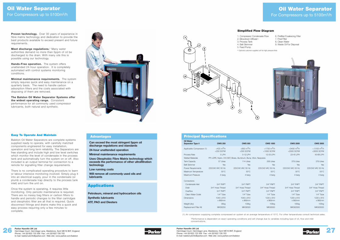
Oil Water SeparatorFor Compressors up to 5100m3/h
Oil Water SeparatorFor Compressors up to 5100m3/h
Proven technology. Over 30 years of experience infibre matrix technology and dedication to provide thebest products available to exceed present and futurerequirements.
Meet discharge regulations.* Many waterauthorities demand no more than 5ppm of oil bedischarged to the drain. With many oils this ispossible using our technology.
Hands-Free operation. The system offersunattended 24-hour operation. It is completelyautomated with control systems monitoringconditions.
Minimal maintenance requirements. The systemsimply requires quick and easy maintenance on aquarterly basis. The need to handle carbonadsorption filters and the costs associated withdisposing of them are removed.
The Balston Oil Water Separator Systems offerthe widest operating range. Consistentperformance for all commonly used compressorlubricants, both natural and synthetic.
Can exceed the most stringent 5ppm oildischarge regulations and standards
24-hour unattended operation
Minimal maintenance requirements
Uses Oleophobic Fibre Matrix technology whichexceeds the performance of other ultrafiltrationtechnology
Low running costs
Will remove all commonly used oils andlubricants
Advantages
Applications
Petroleum, mineral and hydrocarbon oils
Synthetic lubricants
ATF, PAO and Diesters
Easy To Operate And Maintain
Balston Oil Water Separators are complete systemssupplied ready to operate, with carefully matchedcomponents engineered for easy installation,operation and long term reliability. The Separators arefree standing and include high and low level switcheswhich monitor the level of condensate in the processtank and automatically turn the system on or off. Alsoincluded is an output terminal for connection to aremote for signalling filter change requirements.
There is no complicated operating procedure to learnor labour intensive monitoring involved. Simply plug itinto an electrical supply, pour in the condensate (orplumb a condensate trap directly to the process tankinlet) and turn the unit on.
Once the system is operating, it requires littlemonitoring. Only periodic maintenance is required.There are no messy bag filters or carbon filters tohandle and periodic changes to the filter cartridgesand oleophobic filter are all that is required. Quickdisconnect fittings and drains make this a quick andeasy process requiring only a few minutes tocomplete.
Principal SpecificationsOil Water Separator Type # OWS 250 OWS 500 OWS 1000 OWS 2000 OWS 3000
Applicable Compressor (1) <425 m3/h <850 m3/h <1700 m3/h <3400 m3/h < 5100 m3/h<250 SCFM <500 SCFM <1000 SCFM <2000 SCFM <3000 SCFM
Process Rate 5 LPH 5-12 LPH 12-33 LPH 23-45 LPH 45-68 LPH
Wetted Materials PP, LDPE, Nylon, 316 SST, Brass, Aluminum, Buna, Viton, Neoprene
Tank Capacity 57 Litres 114 Litres 208 Litres 379 Litres 379 Litres
Belt Skimmer Yes Yes Yes Yes Yes
Power Requirements 220/240 VAC 50 Hz 220/240 VAC 50 Hz 220/240 VAC 50 Hz 220/240 VAC 50 Hz 220/240 VAC 50 Hz
Maximum Temperature 55°C 55°C 55°C 55°C 55°C
Maximum Pressure 4 barg 4 barg 4 barg 4 barg 4 barg
Connections
Condensate Inlet 3/4" FNPT 3/4" FNPT 3/4" FNPT 3/4" FNPT 3/4" FNPT
Drain 3/4" Hose Thread 3/4" Hose Thread 3/4" Hose Thread 3/4" Hose Thread 3/4" Hose Thread
Overflow 3/4" FNPT 3/4" FNPT 3/4" FNPT 3/4" FNPT 3/4" FNPT
Clean Water Outlet 1/4" Tube 1/4" Tube 1/4" Tube 1/4" Tube 1/4" Tube
Dimensions 1040 x 810 1040 x 810 1220 x 810 1220 x 810 1220 x 810 x 860mm x 860mm x 860mm x 860mm x 860mm
Weight (dry) 95kg 100kg 100kg 105kg 105kg
Replacement Filter Kit MK56250 MK56500 MK56500 MK562000 MK563000
(1) Air compressor supplying complete compressed air system at an average temperature of 15°C. For other temperatures consult technical sales.
*Performance is dependent on exact operating conditions and will change due to variables including type of oil, flow and inlet concentrations.
1. Compressor Condensate Flow2. Blowdown Diffuser(1)
3. Process Tank4. Belt Skimmer5. Feed Pump
Simplified Flow Diagram
6. Prefilter/Coalescing Filter7. Final Filter8. Clean Water9. Waste Oil For Disposal
(1) Optional customer supplied unit for high pressure lines
Parker Hannifin UK LtdHermitage Court, Hermitage Lane, Maidstone, Kent ME16 9NT, EnglandPhone: +44 (0)1622 723 300 Fax: +44 (0)1622 728 703E-mail: [email protected] Web site: www.parker.com/balston
Parker Hannifin UK LtdHermitage Court, Hermitage Lane, Maidstone, Kent ME16 9NT, EnglandPhone: +44 (0)1622 723 300 Fax: +44 (0)1622 728 703E-mail: [email protected] Web site: www.parker.com/balston
28 29
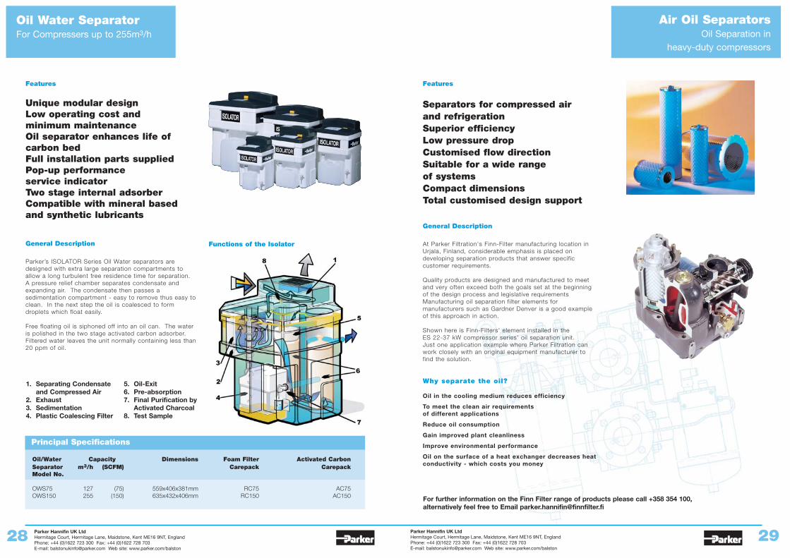
Oil Water SeparatorFor Compressers up to 255m3/h
Features
Unique modular designLow operating cost and minimum maintenanceOil separator enhances life of carbon bedFull installation parts suppliedPop-up performance service indicatorTwo stage internal adsorberCompatible with mineral based and synthetic lubricants
General Description
Parker’s ISOLATOR Series Oil Water separators aredesigned with extra large separation compartments toallow a long turbulent free residence time for separation.A pressure relief chamber separates condensate andexpanding air. The condensate then passes asedimentation compartment - easy to remove thus easy toclean. In the next step the oil is coalesced to formdroplets which float easily.
Free floating oil is siphoned off into an oil can. The wateris polished in the two stage activated carbon adsorber.Filtered water leaves the unit normally containing less than20 ppm of oil.
Air Oil SeparatorsOil Separation in
heavy-duty compressors
Principal Specifications
Oil/Water Capacity Dimensions Foam Filter Activated CarbonSeparator m3/h (SCFM) Carepack CarepackModel No.
OWS75 127 (75) 559x406x381mm RC75 AC75OWS150 255 (150) 635x432x406mm RC150 AC150
Features
Separators for compressed air and refrigerationSuperior efficiencyLow pressure dropCustomised flow directionSuitable for a wide range of systemsCompact dimensionsTotal customised design support
General Description
At Parker Filtration's Finn-Filter manufacturing location inUrjala, Finland, considerable emphasis is placed ondeveloping separation products that answer specificcustomer requirements.
Quality products are designed and manufactured to meetand very often exceed both the goals set at the beginningof the design process and legislative requirementsManufacturing oil separation filter elements formanufacturers such as Gardner Denver is a good exampleof this approach in action.
Shown here is Finn-Filters' element installed in theES 22-37 kW compressor series' oil separation unit.Just one application example where Parker Filtration canwork closely with an original equipment manufacturer tofind the solution.
Why separate the oil?
Oil in the cooling medium reduces efficiency
To meet the clean air requirements of different applications
Reduce oil consumption
Gain improved plant cleanliness
Improve environmental performance
Oil on the surface of a heat exchanger decreases heatconductivity - which costs you money
For further information on the Finn Filter range of products please call +358 354 100, alternatively feel free to Email [email protected]
Functions of the Isolator
1. Separating Condensate and Compressed Air
2. Exhaust3. Sedimentation4. Plastic Coalescing Filter
5. Oil-Exit6. Pre-absorption7. Final Purification by
Activated Charcoal8. Test Sample
Parker Hannifin UK LtdHermitage Court, Hermitage Lane, Maidstone, Kent ME16 9NT, EnglandPhone: +44 (0)1622 723 300 Fax: +44 (0)1622 728 703E-mail: [email protected] Web site: www.parker.com/balston
Parker Hannifin UK LtdHermitage Court, Hermitage Lane, Maidstone, Kent ME16 9NT, EnglandPhone: +44 (0)1622 723 300 Fax: +44 (0)1622 728 703E-mail: [email protected] Web site: www.parker.com/balston
30 31
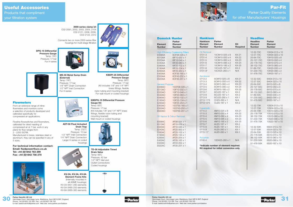
Useful AccessoriesProducts that compliment your filtration system
Par-FitParker Quality Elements
for other Manufacturers’ Housings
Domnick HunterParker
Element ElementNumber Number
High Efficiency Coalescing FiltersE006AA 6CF08-026 x 1E013AA 6IF10-032 x 1E025AA 6IF10-046 x 1E040AA 6IF20-063 x 1E085AA 6IF20-102 x 1E195AA 6IF25-134 x 1E295AA 6IF25-254 x 1E400AA 6CF35-165 x 1E500AA 6CF43-252 x 1E620AA 6CF35-251 x 1
General PurposeE006AO 10CF08-026 x 1E013AO 10IF10-032 x 1E025AO 10IF10-046 x 1E040AO 10IF20-063 x 1E085AO 10IF20-102 x 1E195AO 10IF25-134 x 1E295AO 10IF25-254 x 1E400AO 10CF35-165 x 1E500AO 10CF43-252 x 1E620AO 10CF35-251 x 1
Oil Vapour & Odour Removal
E006AC AF08-026 x 1E013AC AF10-032 x 1E025AC AF10-046 x 1E040AC AF20-063 x 1E085AC AF20-102 x 1E195AC AF25-134 x 1E295AC AF25-254 x 1E400AC AF35-165 x 1E500AC AF43-252 x 1E620AC AF35-251 x 1
HankisonHankison ParkerElement Element Kit Number Number Required
Oil Removal0731-3 10CM10-025 x 8 KX-210731-4 10CM10-050 x 4 KX-220731-5 10CM15-060 x 4 KX-230731-6 10CM15-095 x 2 KX-240731-7 10CM15-185 x 2 KX-250731-8 10CU25-187 x 1 KX-20731-9* 10CH25-260 x 1 N/A
Aerolescer0713-2 6CM10-025 x 8 KX-210713-3 6CM10-050 x 4 KX-220713-4 6CM15-060 x 4 KX-230713-5 6CM15-095 x 2 KX-240713-6 6CM15-185 x 2 KX-250713-7 6CU25-187 x 1 KX-20713-8 6CU25-187 x 1 KX-20713-9 6CU25-260 x 1 KX-10713-11*6 CH25-260 x 1 N/A0713-12*6 CU25-187 x 1 KX-2
Hypersorb0715-2 AM10-025 x 8 KX-210715-3 AM10-050 x 4 KX-220715-4 AM15-060 x 4 KX-230715-5 AM15-095 x 2 KX-240715-6 AM15-185 x 2 KX-250715-7 AU25-187 x 1 KX-20715-8 AU25-187 x 1 KX-20715-9 AU25-260 x 1 KX-10715-11* AU25-260 x 1 KX-1
Accumax0740-4 10DH25-260 x 1 N/A
*Indicate number of element required.Kit required for initial conversion only
HeadlineHeadline ParkerElement ElementNumber Number
12-32-70C 10H04-013 x 1012-57-70C 10H04-023 x 1025-64-70C 10H10-025 x 825-127-70C 10H10-050 x 425-178-70C 10H10-070 x 438-152-70C 10H15-060 x 451-89-70C 10H20-035 x 451-230-70C 10H20-090 x 251-476-70C 10H20-187 x 1
12-32-50C 6H04-013 x 1012-57-50C 6H04-023 x 1025-64-50C 6H10-025 x 825-127-50C 6H10-050 x 425-178-50C 6H10-070 x 438-152-50C 6H15-060 x 451-89-50C 6H20-035 x 451-230-50C 6H20-090 x 251-476-50C 6H20-187 x 1
12-32-70K 10S04-013 x 1012-57-70K 10S04-023 x 1025-64-70K 10S10-025 x 1025-178-70K 10S10-070 x 1038-152-70K 10S15-060 x 1051-230-70K 10S20-090 x 1051-476-70K 10S20-187 x 10
12-32-50K 6S04-013 x 1012-57-50K 6S04-023 x 1025-64-50K 6S10-025 x 1025-178-50K 6S10-070 x 1038-152-50K 6S15-060 x 1051-230-50K 6S20-090 x 1051-476-50K 6S20-187 x 10
2000-series clamp kitC02-2091; 2002, 2003, 2004, 2104
C02-2121; 2206, 2208, CO2-2122, 2312
Connects two or more 2000-series filterhousings for multi-stage filtration
KBDPG-15 Differential PressureGauge KitTemp: 93˚CPressure: 17 bar(Kit includes 1/8” and 1/4” NPT brassfittings, flexible nylon tubing andmounting bracket)Wall mount or coded housings
DPG-15 Differential Pressure Gauge
Temp: 79˚CPressure: 17 bar
For H-series
KV-2A, KV-5A, KV-6AElement Frame Kits(Internally mounted in
all ASME housings)KV-2A XX51-280 elementsKV-5A XX85-250 elementsKV-6A XX85-360 elements
ADT-50 Float ActuatedDrain Trap
Temp: 232˚CPressure: 10 bar
1/2” NPT Inlet Connection1/4” NPT Drain Connection
Larger H-series or codedhousings
TD-50 Adjustable TimedDrain ValveTemp: 66˚CPressure: 42 bar1/2” NPT Inlet andOutlet ConnectionsCoded housings
MS-50 Metal Sump Drain(External)Temp: 79˚CPressure: 17 bar1/8” NPT Drain Connection1/2” NPT Inet ConnectionFor H-series
KBDPI-25 DifferentialPressure Gauge
Temp: 88˚CPressure: 17 bar
(Kit includes 1/8” and 1/4” NPTbrass fittings, flexible
nylon tubing and mounting bracket)For wall mount or coded housings
FlowmetersFrom an extensive range of inlineflowmeters and monitors comea selection of products developed andcalibrated specifically forcompressed air applications.
Flowline flowswitches and flowmeters,calibrated for direct reading ofcompressed air at 7 bar, work in anyplane for flow ranges from2 - 2200 SCFM.Manufactured in brass, stainless steel oraluminium, they can be specified in any of5 sizes.
For technical information contact:Email: [email protected]: +44 (0)1842 763 299Fax: +44 (0)1842 756 270
Parker Hannifin UK LtdHermitage Court, Hermitage Lane, Maidstone, Kent ME16 9NT, EnglandPhone: +44 (0)1622 723 300 Fax: +44 (0)1622 728 703E-mail: [email protected] Web site: www.parker.com/balston
Parker Hannifin UK LtdHermitage Court, Hermitage Lane, Maidstone, Kent ME16 9NT, EnglandPhone: +44 (0)1622 723 300 Fax: +44 (0)1622 728 703E-mail: [email protected] Web site: www.parker.com/balston
32 33
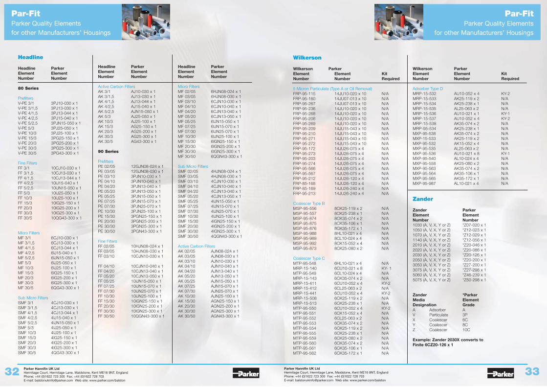
Par-FitParker Quality Elements for other Manufacturers’ Housings
Par-FitParker Quality Elements
for other Manufacturers’ Housings
Headline
Headline ParkerElement ElementNumber Number
80 Series
PrefiltersV-PE 3/1 3PJ10-030 x 1V-PE 3/1,5 3PJ13-030 x 1V-PE 4/1,5 3PJ13-044 x 1V-PE 4/2,5 3PJ15-040 x 1V-PE 5/2,5 3PJN15-050 x 1V-PE 5/3 3PJ25-050 x 1V-PE 10/3 3PJ25-100 x 1V-PE 15/3 3PG25-150 x 1V-PE 20/3 3PG25-200 x 1V-PE 30/3 3PG25-300 x 1V-PE 30/5 3PG43-300 x 1
Fine FiltersFF 3/1 10CJ10-030 x 1FF 3/1,5 10CJ13-030 x 1FF 4/1,5 10CJ13-044 x 1FF 4/2,5 10IJ15-040 x 1FF 5/2,5 10IJN15-050 x 1FF 5/3 10IJ25-050 x 1FF 10/3 10IJ25-100 x 1FF 15/3 10IG25-150 x 1FF 20/3 10IG25-200 x 1FF 30/3 10IG25-300 x 1FF 30/5 10QG43-300 x 1
Micro FiltersMF 3/1 6CJ10-030 x 1MF 3/1,5 6CJ13-030 x 1MF 4/1,5 6CJ13-044 x 1MF 4/2,5 6IJ15-040 x 1MF 5/2,5 6IJN15-050 x 1MF 5/3 6IJ25-050 x 1MF 10/3 6IJ25-100 x 1MF 15/3 6IG25-150 x 1MF 20/3 6IG25-200 x 1MF 30/3 6IG25-300 x 1MF 30/5 6QG43-300 x 1
Sub Micro FiltersSMF 3/1 4CJ10-030 x 1SMF 3/1,5 4CJ13-030 x 1SMF 4/1,5 4CJ13-044 x 1SMF 4/2,5 4IJ15-040 x 1SMF 5/2,5 4IJN15-050 x 1SMF 5/3 4IJ25-050 x 1SMF 10/3 4IJ25-100 x 1SMF 15/3 4IG25-150 x 1SMF 20/3 4IG25-200 x 1SMF 30/3 4IG25-300 x 1SMF 30/5 4QG43-300 x 1
Headline ParkerElement ElementNumber Number
Active Carbon FiltersAK 3/1 AJ10-030 x 1AK 3/1,5 AJ13-030 x 1AK 4/1,5 AJ13-044 x 1AK 4/2,5 AJ15-040 x 1AK 5/2,5 AJN15-050 x 1AK 5/3 AJ25-050 x 1AK 10/3 AJ25-100 x 1AK 15/3 AG25-150 x 1AK 20/3 AG25-200 x 1AK 30/3 AG25-300 x 1AK 30/5 AG43-300 x 1
90 Series
PrefiltersPE 02/05 12GJN08-024 x 1PE 03/05 12GJN08-030 x 1PE 03/10 3PJN10-030 x 1PE 04/10 3PJN10-040 x 1PE 04/20 3PJN13-040 x 1PE 05/20 3PJN13-050 x 1PE 05/25 3PJN15-050 x 1PE 07/25 3PJN15-070 x 1PE 07/30 3PJN25-070 x 1PE 10/30 3PJN25-100 x 1PE 15/30 3PGN25-150 x 1PE 20/30 3PGN25-200 x 1PE 30/30 3PGN25-300 x 1PE 30/50 3PGN43-300 x 1
Fine FiltersFF 02/05 10HJN08-024 x 1FF 03/05 10HJN08-030 x 1FF 03/10 10CJN10-030 x 1
FF 04/10 10CJN10-040 x 1FF 04/20 10CJN13-040 x 1FF 05/20 10CJN13-050 x 1FF 05/25 10IJN15-050 x 1FF 07/25 10IJN15-070 x 1FF 07/30 10IJN25-070 x 1FF 10/30 10IJN25-100 x 1FF 15/30 10IGN25-150 x 1FF 20/30 10IGN25-200 x 1FF 30/30 10IGN25-300 x 1FF 30/50 10QGN43-300 x 1
Headline ParkerElement ElementNumber Number
Micro FiltersMF 02/05 6HJN08-024 x 1MF 03/05 6HJN08-030 x 1MF 03/10 6CJN10-030 x 1MF 04/10 6CJN10-040 x 1MF 04/20 6CJN13-040 x 1MF 05/20 6CJN13-050 x 1MF 05/25 6IJN15-050 x 1MF 07/25 6IJN15-070 x 1MF 07/30 6IJN25-070 x 1MF 10/30 6IJN25-100 x 1MF 15/30 6IGN25-150 x 1MF 20/30 6IGN25-200 x 1MF 30/30 6IGN25-300 x 1MF 30/50 6QGN43-300 x 1
Sub Micro FiltersSMF 02/05 4HJN08-024 x 1SMF 03/05 4HJN08-030 x 1SMF 03/10 4CJN10-030 x 1SMF 04/10 4CJN10-040 x 1SMF 04/20 4CJN13-040 x 1SMF 05/20 4CJN13-050 x 1SMF 05/25 4IJN15-050 x 1SMF 07/25 4IJN15-070 x 1SMF 07/30 4IJN25-070 x 1SMF 10/30 4IJN25-100 x 1SMF 15/30 4IGN25-150 x 1SMF 20/30 4IGN25-200 x 1SMF 30/30 4IGN25-300 x 1SMF 30/50 4QGN43-300 x 1
Active Carbon FiltersAK 02/05 AJN08-024 x 1AK 03/05 AJN08-030 x 1AK 03/10 AJN10-030 x 1AK 04/10 AJN10-040 x 1AK 04/20 AJN13-040 x 1AK 05/20 AJN13-050 x 1AK 05/25 AJN15-050 x 1AK 07/25 AJN15-070 x 1AK 07/30 AJN25-070 x 1AK 10/30 AJN25-100 x 1AK 15/30 AGN25-150 x 1AK 20/30 AGN25-200 x 1AK 30/30 AGN25-300 x 1AK 30/50 AGN43-300 x 1
Wilkerson
Wilkerson ParkerElement Element KitNumber Number Required
5 Micron Particulate (Type A or Oil Removal)FRP-95-115 14JU10-020 x 10 N/AFRP-95-160 14JU07-013 x 10 N/AFRP-95-267 14JU07-013 x 10 N/AFRP-95-236 14JU10-020 x 10 N/AFRP-95-268 14JU10-020 x 10 N/AFRP-95-206 14JU10-020 x 10 N/AFRP-95-269 14JU10-020 x 10 N/AFRP-95-209 14JU15-043 x 10 N/AFRP-95-210 14JU15-043 x 10 N/AFRP-95-271 14JU15-043 x 10 N/AFRP-95-272 14JU15-043 x 10 N/AFRP-95-172 14JU26-075 x 4 N/AFRP-95-273 14JU26-075 x 4 N/AFRP-95-203 14JU26-075 x 4 N/AFRP-95-274 14JU26-075 x 4 N/AFRP-95-566 14JU26-075 x 4 N/AFRP-95-567 14JU26-075 x 4 N/AFRP-95-212 14JU26-120 x 4 N/AFRP-85-168 14JU26-120 x 4 N/AFRP-85-169 14JU26-240 x 4 N/AFRP-95-213 14JU26-240 x 4 N/A
Coalescer Type BMSP-95-556 8CK25-119 x 2 N/AMSP-95-557 8CK25-238 x 1 N/AMSP-95-874 8CK35-074 x 2 N/AMSP-95-875 8CK35-106 x 1 N/AMSP-95-876 8CK35-172 x 1 N/A MSP-95-988 8HL10-021 x 4 N/AMSP-95-989 8CL10-024 x 4 N/AMSP-95-992 8CK15-052 x 4 N/AMSP-95-873 8CK25-080 x 2 N/A
Coalescer Type CMTP-95-548 6HL10-021 x 4 N/AMRP-15-140 6CU10-021 x 8 KY- 1MTP-95-549 6CL10-024 x 4 N/AMRP-15-143 6CK35-074 x 2 N/AMRP-15-411 6CU10-052 x 4 KY-2MRP-15-412 6CL25-063 x 2 N/AMRP-15-441 6CU10-052 x 4 KY-2MRP-15-508 6CK25-119 x 2 N/AMRP-15-513 6CK25-238 x 1 N/AMTP-95-550 6CU10-052 x 4 KY-2MTP-95-551 6CK15-052 x 4 N/AMTP-95-552 6CL25-063 x 2 N/AMTP-95-553 6CK35-074 x 2 N/AMTP-95-554 6CK25-119 x 2 N/AMTP-95-555 6CK25-238 x 1 N/AMTP-95-559 6CK25-080 x 2 N/AMTP-95-560 6CK35-074 x 2 N/AMTP-95-561 6CK35-106 x 1 N/AMTP-95-562 6CK35-172 x 1 N/A
Wilkerson ParkerElement Element KitNumber Number Required
Adsorber Type DMRP-15-532 AU10-052 x 4 KY-2MRP-15-533 AK25-119 x 2 N/AMRP-15-534 AK25-238 x 1 N/AMRP-15-535 AL25-063 x 2 N/AMRP-15-536 AU10-021 x 1 KY-1MRP-15-537 AU10-052 x 4 KY-2MRP-15-538 AK35-074 x 2 N/AMRP-95-534 AK25-238 x 1 N/AMXP-95-538 AK35-074 x 2 N/AMXP-15-533 AK25-119 x 2 N/AMXP-95-532 AK15-052 x 4 N/AMXP-95-535 AL25-063 x 2 N/AMXP-95-536 AU10-021 x 8 KY-1MXP-95-540 AL10-024 x 4 N/AMXP-95-558 AK25-080 x 2 N/AMXP-95-563 AK35-074 x 2 N/AMXP-95-564 AK35-106 x 1 N/AMXP-95-565 AK35-172 x 1 N/AMXP-95-987 AL10-021 x 4 N/A
Zander
Zander ParkerElement ElementNumber Number1030 (A, V, X, Y or Z) *Z07-020 x 11050 (A, V, X, Y or Z) *Z12-023 x 11070 (A, V, X, Y or Z) *Z12-029 x 11140 (A, V, X, Y or Z) *Z12-056 x 12010 (A, V, X, Y or Z) *Z20-046 x 12020 (A, V, X, Y or Z) *Z20-086 x 12030 (A, V, X, Y or Z) *Z20-126 x 12050 (A, V, X, Y or Z) *Z20-200 x 13050 (A, V, X, Y or Z) *Z27-200 x 13075 (A, V, X, Y or Z) *Z27-298 x 15060 (A, V, X, Y or Z) *Z46-239 x 15075 (A, V, X, Y or Z) *Z50-298 x 1
Zander *ParkerMedia Element Designation GradeA Adsorber AV Particulate 3PX Coalescer 6CY Coalescer 8CZ Coalescer 10C
Example: Zander 2030X converts to Finite 6CZ20-126 x 1
Parker Hannifin UK LtdHermitage Court, Hermitage Lane, Maidstone, Kent ME16 9NT, EnglandPhone: +44 (0)1622 723 300 Fax: +44 (0)1622 728 703E-mail: [email protected] Web site: www.parker.com/balston
Parker Hannifin UK LtdHermitage Court, Hermitage Lane, Maidstone, Kent ME16 9NT, EnglandPhone: +44 (0)1622 723 300 Fax: +44 (0)1622 728 703E-mail: [email protected] Web site: www.parker.com/balston
34 35
Par-FitAir/Oil Separators
Filters and Dryers forOEM Solutions
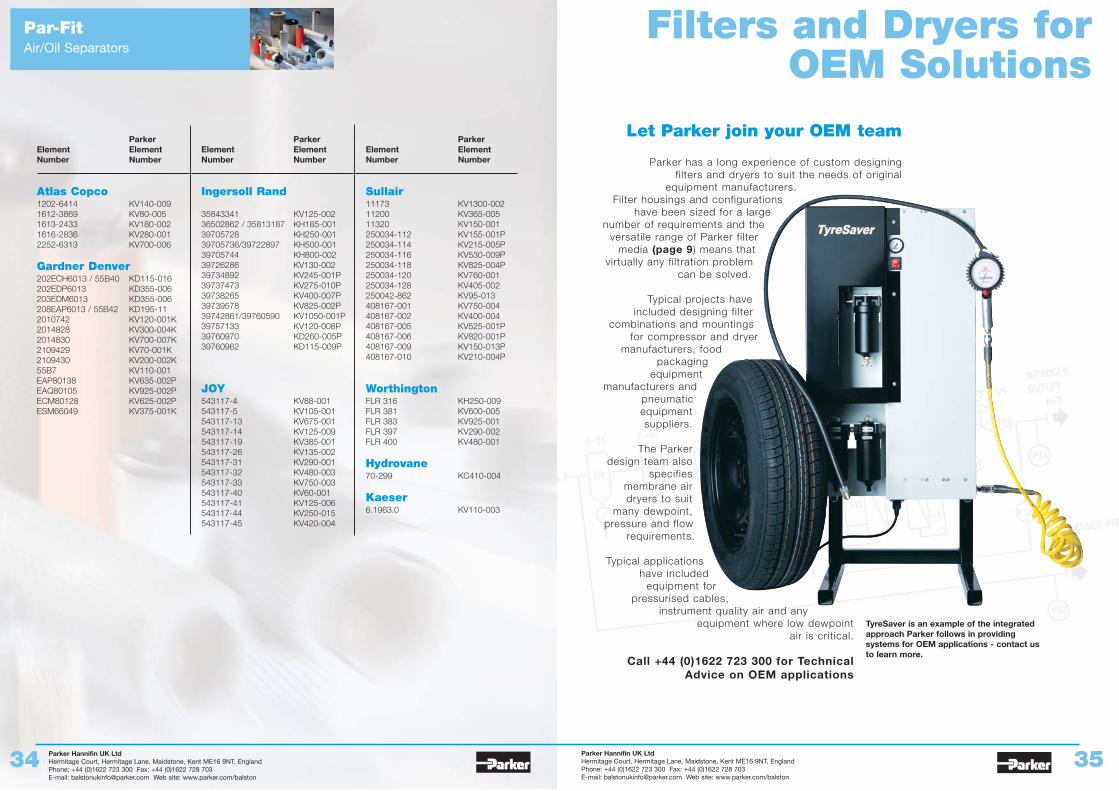
Let Parker join your OEM team
Parker has a long experience of custom designing filters and dryers to suit the needs of original
equipment manufacturers.Filter housings and configurations
have been sized for a largenumber of requirements and the
versatile range of Parker filtermedia (page 9) means that
virtually any filtration problemcan be solved.
Typical projects haveincluded designing filter
combinations and mountingsfor compressor and dryer
manufacturers, foodpackaging
equipmentmanufacturers and
pneumaticequipmentsuppliers.
The Parkerdesign team also
specifiesmembrane airdryers to suit
many dewpoint,pressure and flow
requirements.
Typical applicationshave included
equipment forpressurised cables,
instrument quality air and any equipment where low dewpoint
air is critical.
Call +44 (0)1622 723 300 for TechnicalAdvice on OEM applications
ParkerElement ElementNumber Number
Atlas Copco1202-6414 KV140-0091612-3869 KV80-0051613-2433 KV180-0021616-2836 KV280-0012252-6313 KV700-006
Gardner Denver202ECH6013 / 55B40 KD115-016202EDP6013 KD355-006203EDM6013 KD355-006208EAP6013 / 55B42 KD195-112010742 KV120-001K2014828 KV300-004K2014830 KV700-007K2109429 KV70-001K2109430 KV200-002K55B7 KV110-001EAP80138 KV635-002PEAQ80105 KV925-002PECM80128 KV625-002PESM66049 KV375-001K
ParkerElement ElementNumber Number
Ingersoll Rand
35843341 KV125-00236502862 / 35813187 KH185-00139705728 KH250-00139705736/39722897 KH500-00139705744 KH800-00239726286 KV130-00239734892 KV245-001P39737473 KV275-010P39738265 KV400-007P39739578 KV825-002P39742861/39760590 KV1050-001P39757133 KV120-008P39760970 KD260-005P39760962 KD115-009P
JOY543117-4 KV88-001543117-5 KV105-001543117-13 KV675-001543117-14 KV125-009543117-19 KV385-001543117-26 KV135-002543117-31 KV290-001543117-32 KV480-003543117-33 KV750-003543117-40 KV60-001543117-41 KV125-006543117-44 KV250-015543117-45 KV420-004
ParkerElement ElementNumber Number
Sullair11173 KV1300-00211200 KV365-00511320 KV150-001250034-112 KV155-001P250034-114 KV215-005P250034-116 KV530-009P250034-118 KV825-004P250034-120 KV760-001250034-128 KV405-002250042-862 KV95-013408167-001 KV750-004408167-002 KV400-004408167-005 KV525-001P408167-006 KV820-001P408167-009 KV150-013P408167-010 KV210-004P
WorthingtonFLR 316 KH250-009FLR 381 KV600-005FLR 383 KV925-001FLR 397 KV290-002FLR 400 KV480-001
Hydrovane70-299 KC410-004
Kaeser6.1963.0 KV110-003
TyreSaver is an example of the integratedapproach Parker follows in providingsystems for OEM applications - contact usto learn more.
Every effort has been made to ensure the accuracy of this document at the time of printing. In accordance with company’s policy of continued productimprovement Parker Hannifin UK Ltd reserves the right to make product changes without notice. No liability is accepted for any consequential losses, injury ordamage resulting from the use of this document or from any omissions or errors herein. The data is given for guidance only. It does not constitute aspecification or an offer for sale. The products are always subject to a programme of improvement and testing which may result in some changes in thecharacteristics quoted. As the products may be used by the client in circumstances beyond the knowledge and control of Parker Hannifin UK Ltd, we cannotgive any warranty as to the relevance of these particulars to an application. It is the client’s responsibility to carry out the necessary tests to determine theusefulness of the products and to ensure their safety of operation in a particular application.
About the Parker Hannifin Corporation
Aerospace GroupA leader in the development,
design, manufacture and service
of control systems and
components for aerospace
and related high technology
markets, achieving profitable
growth through premier
customer service. AutomationGroupA leading supplier of
pneumatic and electro
mechanical components and
systems to automation
customers worldwide.
Climate &Industrial Controls GroupDesigns, manufactures and
markets system control and fluid
handling components and
systems to refrigeration, air
conditioning and industrial
customers worldwide. Filtration GroupDesigns, manufactures and
markets quality filtration and
clarification products, providing
customers with the best value,
quality, technical support and
global availability.
Fluid ConnectorsGroupDesigns, manufactures and
markets rigid and flexible
connectors and associated
products used in pneumatic and
fluid systems. Hydraulics GroupDesigns, produces and markets
a full spectrum of hydraulic
components and systems to
builders and users of industrial
and mobile machinery
and equipment.
Instrumentation GroupA global leader in the design,
manufacture and distribution
of high quality critical flow
components for worldwide
process instrumentation, ultra
high purity, medical and
analytical applications.Seal GroupDesigns, manufactures and
distributes industrial and
commercial sealing devices
and related products by
providing superior quality and
total customer satisfaction.
Filtration Group TechnicalSales & Service Locations
Parker Hannifin CorporationFiltration and Separation Division100 Ames Pond Drive, PO Box 1262Tewksbury, MA 01876-0962 USAPhone: +1 800 343 4048Fax: +1 978 858 0625
Parker Hannifin CorporationProcess Filter Division6640 Intech BlvdIndianapolis, IN 46278Phone: +1 317 275 8300Fax: +1 317 275 8410
Parker Hannifin CorporationRacor Division3400 Finch RoadPO Box 3208Modesto, CA 95353 USAPhone: +1 800 344-3286Phone: +1 209 521-7860Fax: +1 209 529-3278
Parker Hannifin CorporationHydraulic Filter Division16810 Fulton County Rd 2Metamora, OH 43540-9714 USAPhone: +1 419 644-4311Fax: +1 419 644-6205
Parker Hannifin UK Ltd.Filter Division Europe HQ,Shaw Cross Business Park,Dewsbury, West YorkshireWF12 7RD UKPhone: +44 (0)1924 487 000Fax: +44 (0)1924 487 038
Parker Hannifin Ind.eCom.Ltda.Filter DivisionVia Anhanguera, Km. 25,305276-977-Sao Paulo–SP, BrazilPhone: 55 (11) 3917 1407Fax: 55 (11) 3917 1623
Parker Hannifin Asia Pacific Company, LTD902 Dae Heung Bldg.648-23 Yeoksam-dongKangnam-ku, Seoul,Korea 135-080Phone: 82 2 561 0414Fax; 82 2 556 8187
Parker European Sales Offices
Austria + 43 2622 235013Belgium +32 67 280900Czech Republic +420 2 83085221Denmark +45 43 560400Finland +358 3 54100France +33 254 740304Germany +49 2131 513350Hungary 36 1 2528137Italy +39 02 451921Netherlands +31 541 585000Norway +47 64911000Poland +48 22 8634942Spain + 34 91 6757300Sweden + 46 8 59795000Switzerland +41 22 3077111
Distributor
Catalogue B002GB
Parker Hannifin UK Ltd Filter Division EuropeHermitage Court, Hermitage Lane, Maidstone, Kent ME16 9NT, UKPhone: +44 (0)1622 723 300 Fax: +44 (0)1622 728 703E-mail: [email protected] Web site: www.parker.com/balston
Member of British Compressed Air Society
Where Required