Embed Size (px)
DESCRIPTION
This seminar will help you to understand how different factors affect compression of powdered solids.
Citation preview

1
Compression and consolidation of Compression and consolidation of powder solidspowder solids
Compression and consolidation of Compression and consolidation of powder solidspowder solids
Presented by Presented by PAYAL H. PATIL (M.pharm 1PAYAL H. PATIL (M.pharm 1stst yr.) yr.)
Dept. of pharmaceutics and Q.ADept. of pharmaceutics and Q.AR.C.Patel Institute of Pharmaceutical Education and R.C.Patel Institute of Pharmaceutical Education and
Research, Shirpur.Research, Shirpur. 1
2
CONTENTS DEFINATIONS
DERIVED PROPERTIES OF POWDERED SOLID
EFFECT OF APPLIED FORCES ON COMPRESSION
GRANULATION
COMPRESSION & CONSOLIDATION UNDER HIGH LOAD
FORCE VOLUME RELATIONSHIP
HECKEL PLOT
KAWAKITA EQUATION
COOPER & EATON EQUATION
DECOMPRESSION
COMPACTION PROFILE
ENERGY OF COMPRESSION
REFERENCES2
3
Definitions
• Compression- Compression means reduction of bulk volume of material as a result of displacement of gaseous phase.
• Consolidation – Consolidation is an increase in mechanical strength of material from particle - particle interactions.
3
4
Derived properties of powdered solids
1. The solid-air interface
2. Angle of repose
3. Flow rates
4. Mass-volume relationships
5. Density
4
5
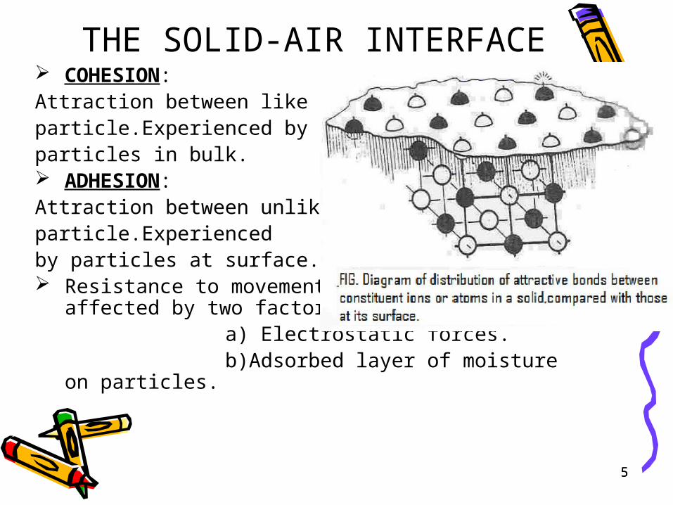
THE SOLID-AIR INTERFACE COHESION:Attraction between likeparticle.Experienced by particles in bulk. ADHESION: Attraction between unlikeparticle.Experiencedby particles at surface. Resistance to movement of particles is affected by two
factors:- a) Electrostatic forces. b)Adsorbed layer of moisture on particles.
5
6
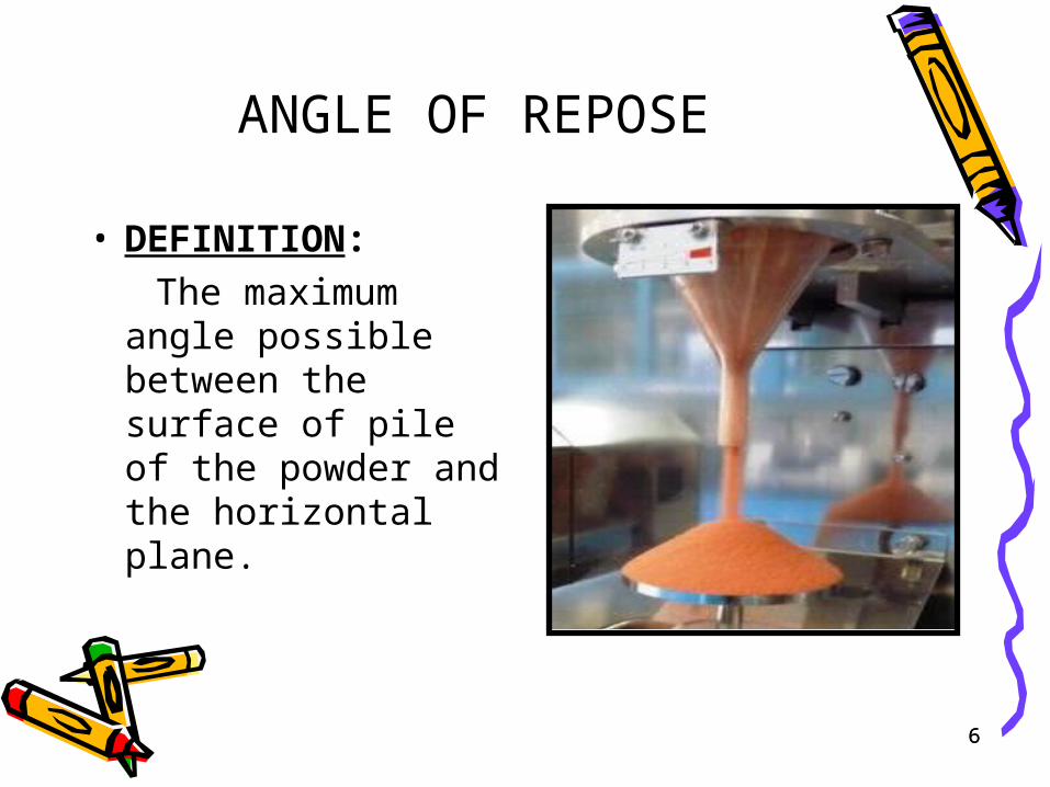
ANGLE OF REPOSE
• DEFINITION:
The maximum angle possible between the surface of pile of the powder and the horizontal plane.
6
7
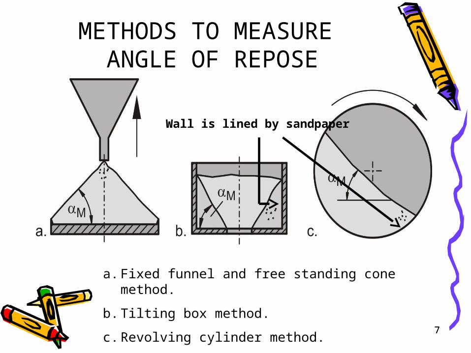
METHODS TO MEASURE ANGLE OF REPOSE
a. Fixed funnel and free standing cone method.
b. Tilting box method.
c. Revolving cylinder method.
Wall is lined by sandpaper
7
8
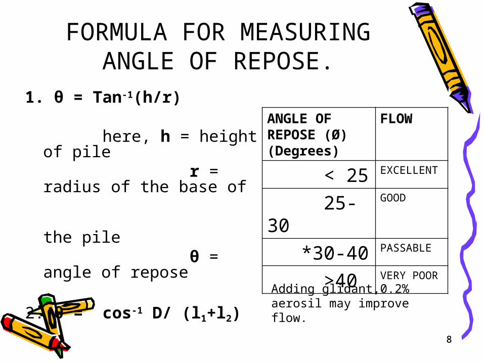
FORMULA FOR MEASURING ANGLE OF REPOSE.
1. θ = Tan-1(h/r) here, h = height of pile r = radius of the base of
the pile θ = angle of repose
2. θ = cos-1 D/ (l1+l2)
here, D = diameter of base l1+l2 = the opposite sides of pile
ANGLE OF REPOSE (Ø) (Degrees)
FLOW
< 25 EXCELLENT
25-30 GOOD
*30-40 PASSABLE
>40 VERY POOR
Adding glidant,0.2% aerosil may improve flow.
8
9
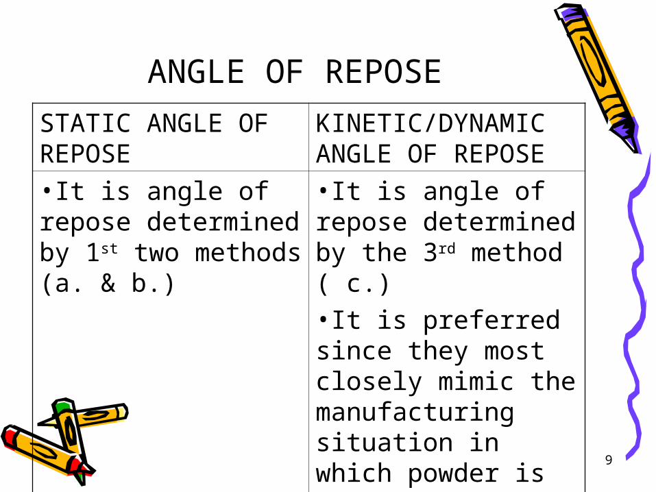
ANGLE OF REPOSE
STATIC ANGLE OF REPOSE
KINETIC/DYNAMIC ANGLE OF REPOSE
•It is angle of repose determined by 1st two methods (a. & b.)
•It is angle of repose determined by the 3rd method ( c.)•It is preferred since they most closely mimic the manufacturing situation in which powder is in motion.
10
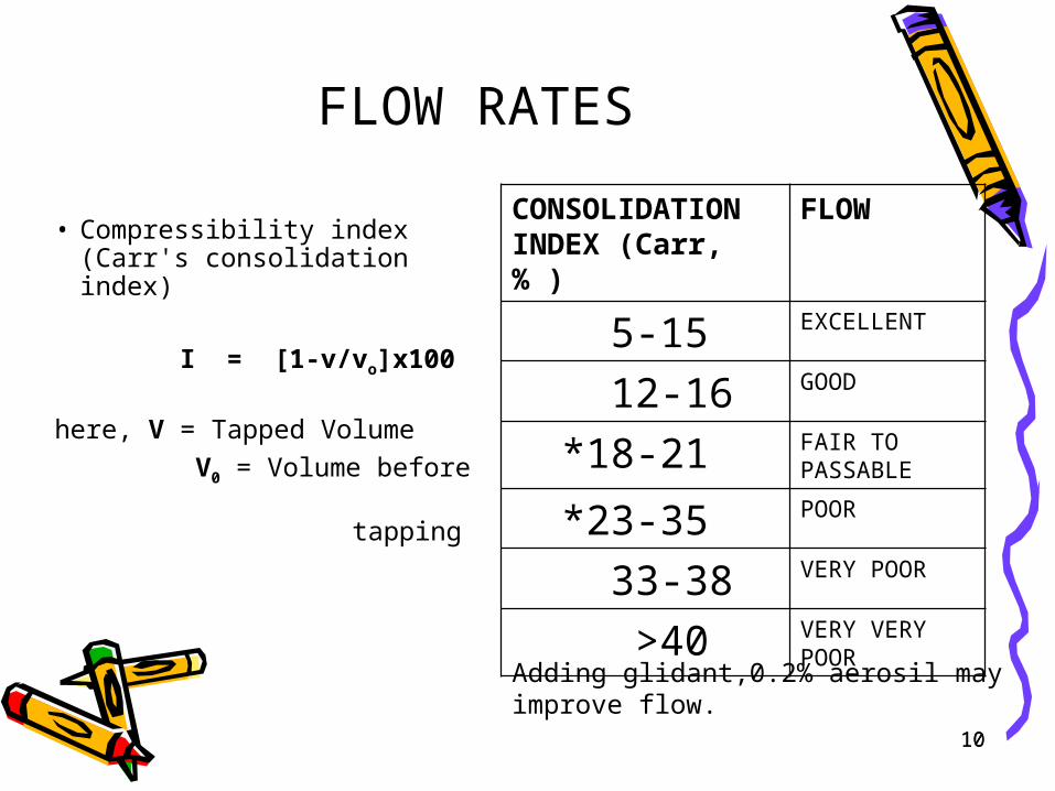
FLOW RATES
• Compressibility index (Carr's consolidation index)
I = [1-v/vo]x100 here, V = Tapped Volume
V0 = Volume before tapping
CONSOLIDATION INDEX (Carr, % )
FLOW
5-15 EXCELLENT
12-16 GOOD
*18-21 FAIR TO PASSABLE
*23-35 POOR
33-38 VERY POOR
>40 VERY VERY POOR
Adding glidant,0.2% aerosil may improve flow.
10
11
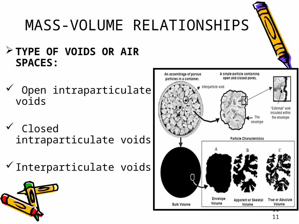
MASS-VOLUME RELATIONSHIPS
TYPE OF VOIDS OR AIR SPACES:
Open intraparticulate voids
Closed intraparticulate voids
Interparticulate voids
11
12
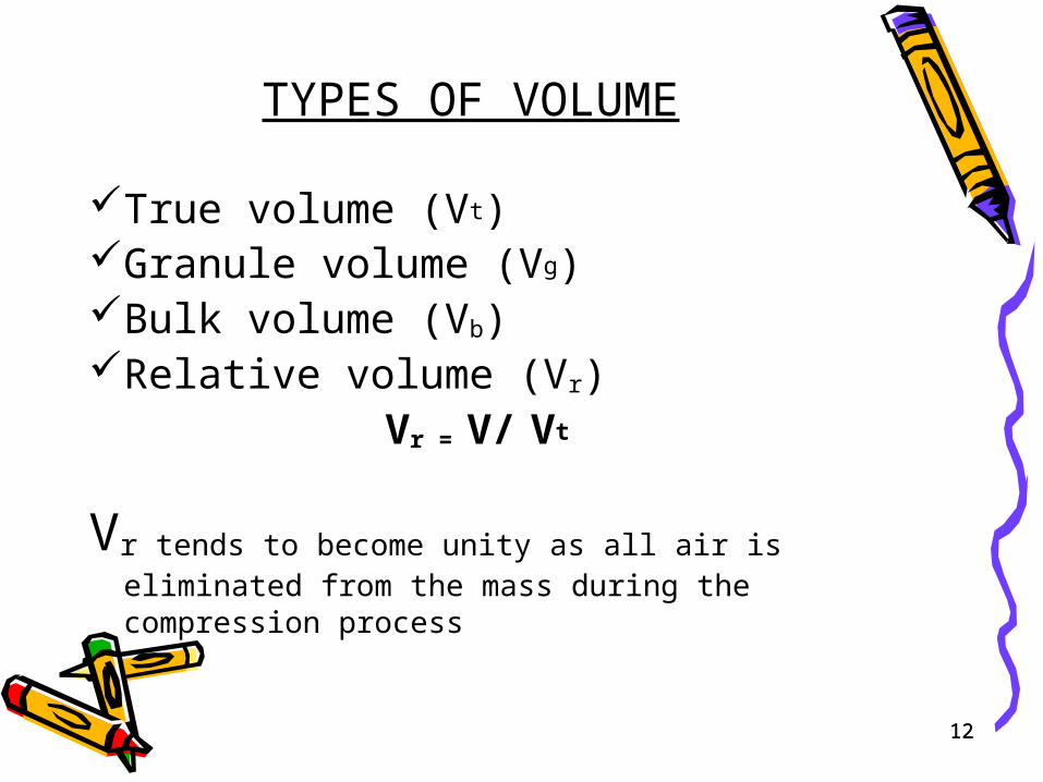
TYPES OF VOLUME
True volume (Vt)Granule volume (Vg)Bulk volume (Vb) Relative volume (Vr) Vr = V/ Vt
Vr tends to become unity as all air is eliminated from the mass during the compression process
12
13
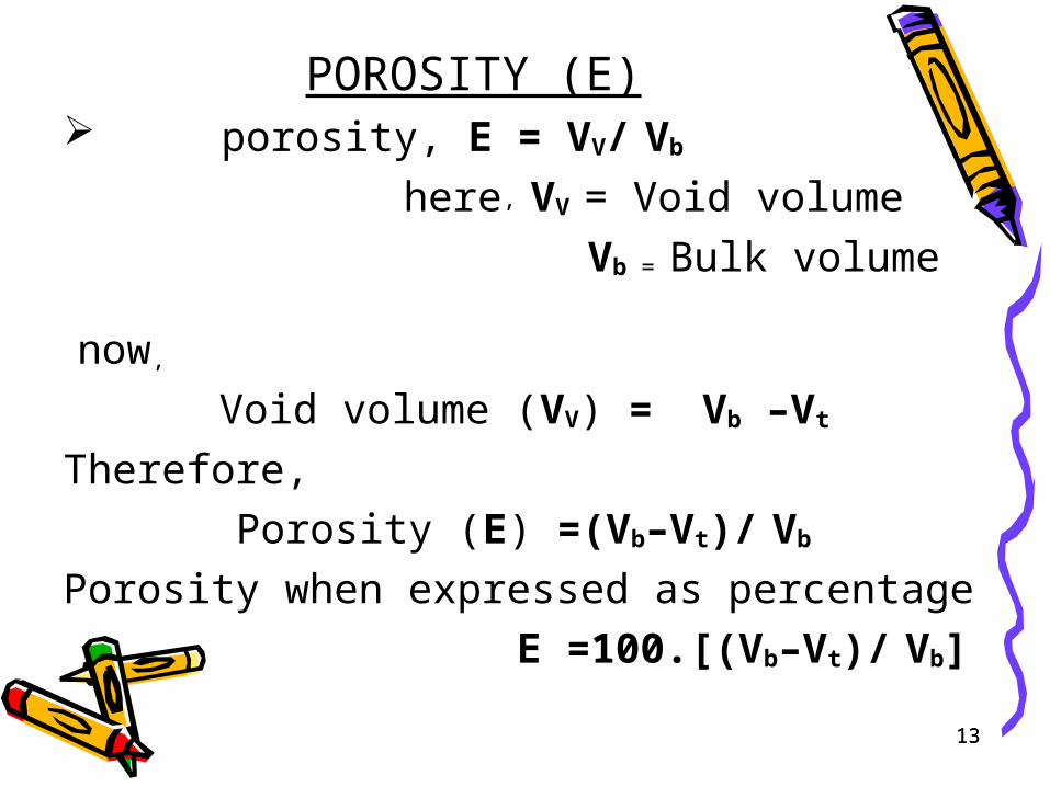
POROSITY (E) porosity, E = VV/ Vb
here, VV = Void volume
Vb = Bulk volume
now,
Void volume (VV) = Vb –Vt
Therefore,
Porosity (E) =(Vb–Vt)/ Vb
Porosity when expressed as percentage
E =100.[(Vb–Vt)/ Vb]13
14
METHODS TO MEASURE VOLUME OF POWDER.
Helium pycnometer
Liquid displacement method (specific gravity bottle method)
14
15
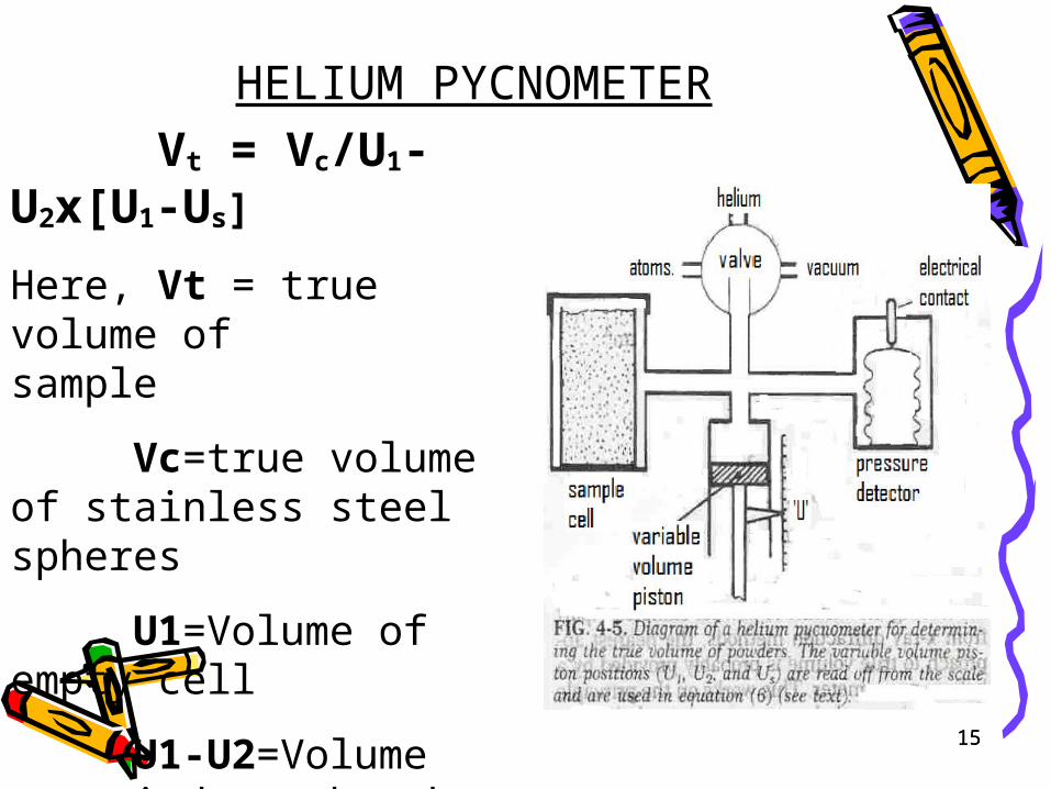
HELIUM PYCNOMETER
Vt = Vc/U1-U2x[U1-Us]
Here, Vt = true volume of sample
Vc=true volume of stainless steel spheres
U1=Volume of empty cell
U1-U2=Volume occupied by the std. sample
U1-Us = volume
occupied by sample
15
16
HELIUM PYCNOMETER
17
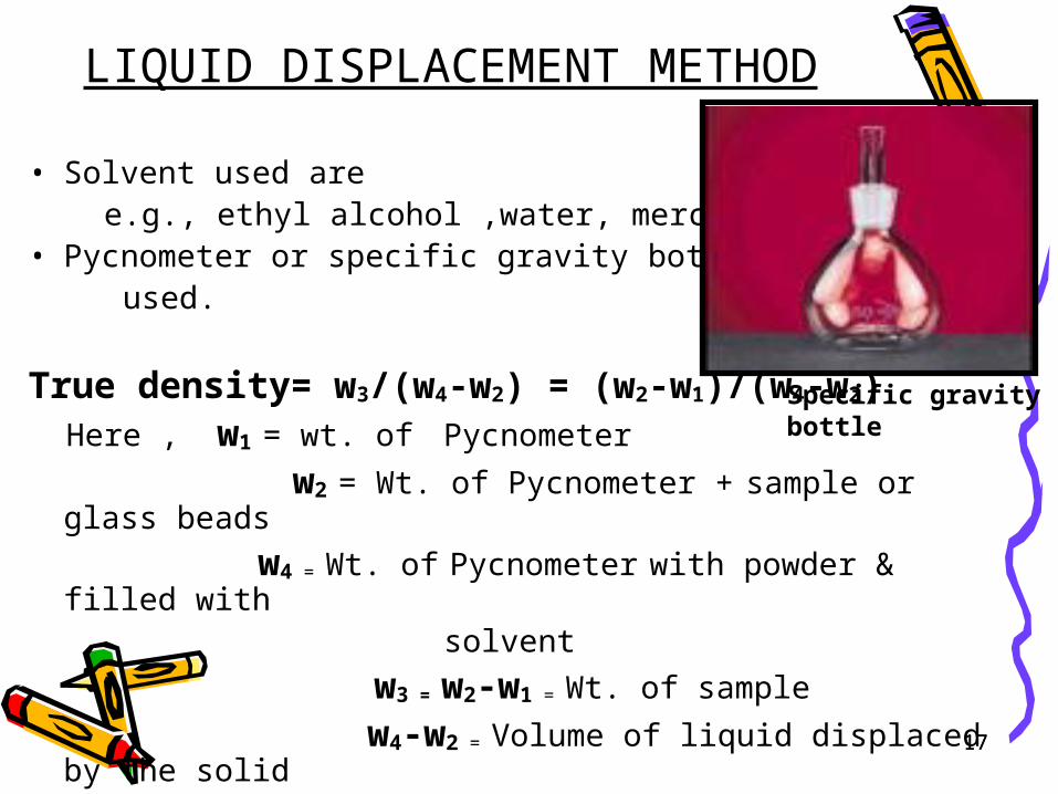
LIQUID DISPLACEMENT METHOD
• Solvent used are e.g., ethyl alcohol ,water, mercury , etc.• Pycnometer or specific gravity bottle used.
True density= w3/(w4-w2) = (w2-w1)/(w4-w2) Here , w1 = wt. of Pycnometer
w2 = Wt. of Pycnometer + sample or glass beads
w4 = Wt. of Pycnometer with powder & filled with solvent
w3 = w2-w1 = Wt. of sample
w4-w2 = Volume of liquid displaced by the solid
Specific gravity bottle
17
18
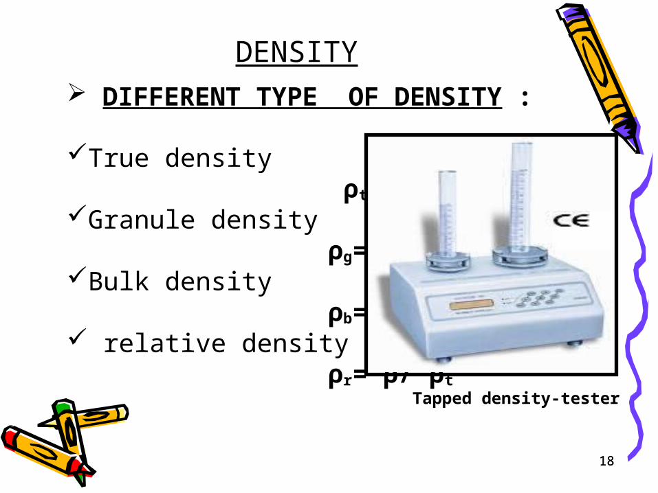
DENSITY DIFFERENT TYPE OF DENSITY :
True density ρt=M/vt
Granule density ρg=M/vg
Bulk density ρb=M/vb
relative density ρr= ρ/ ρt
Tapped density-tester
18
19
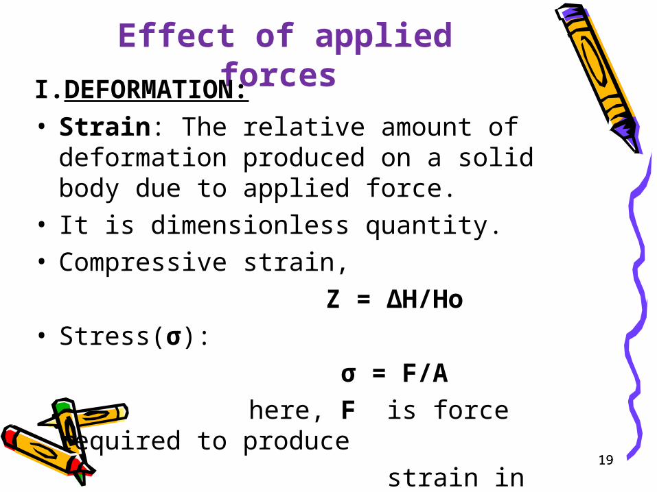
Effect of applied forces
I. DEFORMATION:
• Strain: The relative amount of deformation produced on a solid body due to applied force.
• It is dimensionless quantity.• Compressive strain,
Z = ∆H/Ho
• Stress(σ):
σ = F/A
here, F is force required to produce
strain in area A
19
20
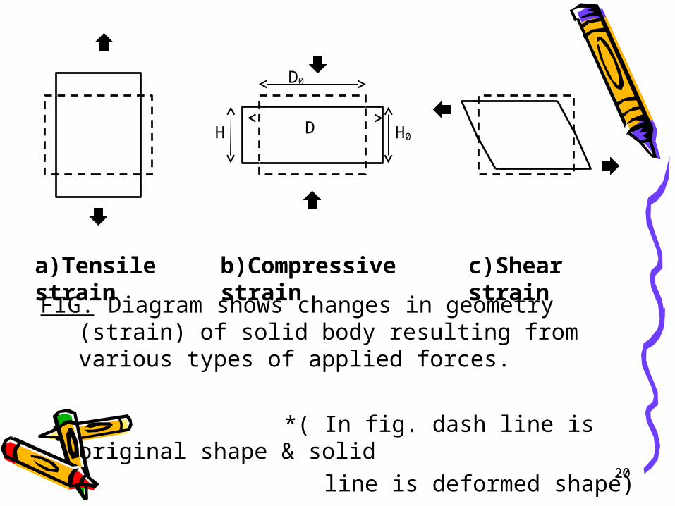
a)Tensile strain b)Compressive strain c)Shear strain
FIG. Diagram shows changes in geometry (strain) of solid body resulting from various types of applied forces.
*( In fig. dash line is original shape & solid
line is deformed shape)
H H0D
D0
20
21
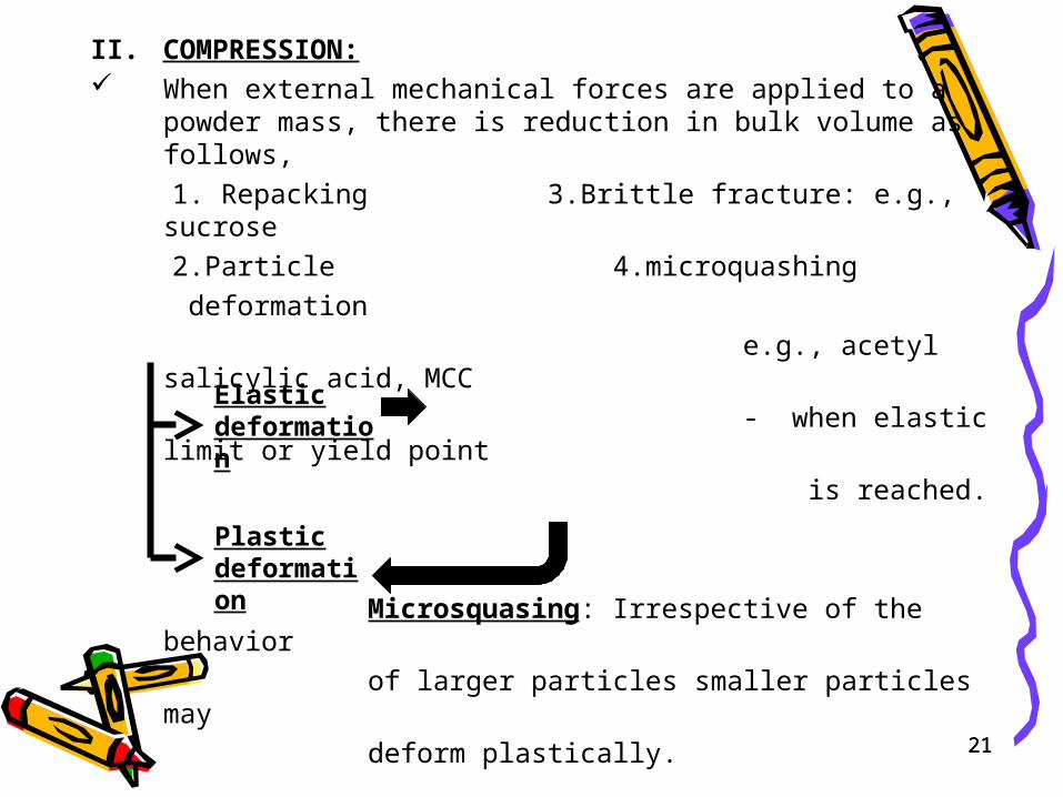
II. COMPRESSION: When external mechanical forces are applied to a
powder mass, there is reduction in bulk volume as follows,
1. Repacking 3.Brittle fracture: e.g., sucrose
2.Particle 4.microquashing
deformation
e.g., acetyl salicylic acid, MCC
- when elastic limit or yield point
is reached.
Microsquasing: Irrespective of the behavior
of larger particles smaller particles may
deform plastically.
Elastic deformation
Plastic deformation
21
22
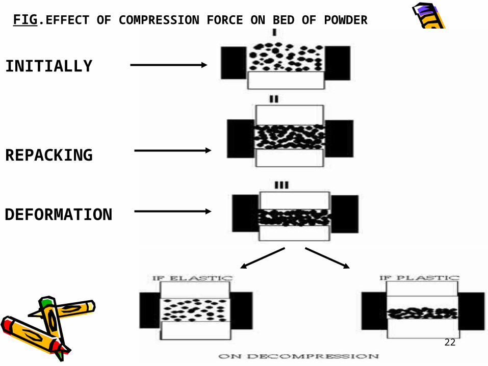
INITIALLY
REPACKING
DEFORMATION
FIG.EFFECT OF COMPRESSION FORCE ON BED OF POWDER
22
23
III. CONSOLIDATION:
Mechanism,
1.Cold welding (particle distance <50nm)
2.Fusion welding (caused due to frictional
heat)
3.Recrystallization Consolidation process is influenced by,
- Chemical Nature of materials
- Extent of available surface
- presence of surface contaminants
- Intersurface distance
23
24
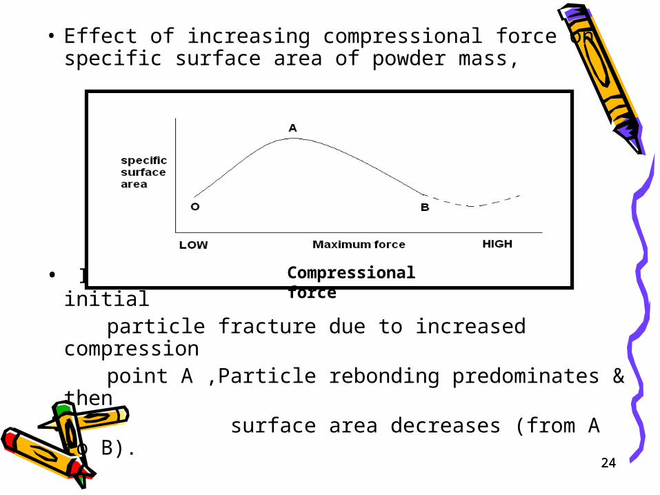
• Effect of increasing compressional force on specific surface area of powder mass,
• Increased surface area (from O to A), initial particle fracture due to increased compression point A ,Particle rebonding predominates & then
surface area decreases (from A to B).
Compressional force
24
25
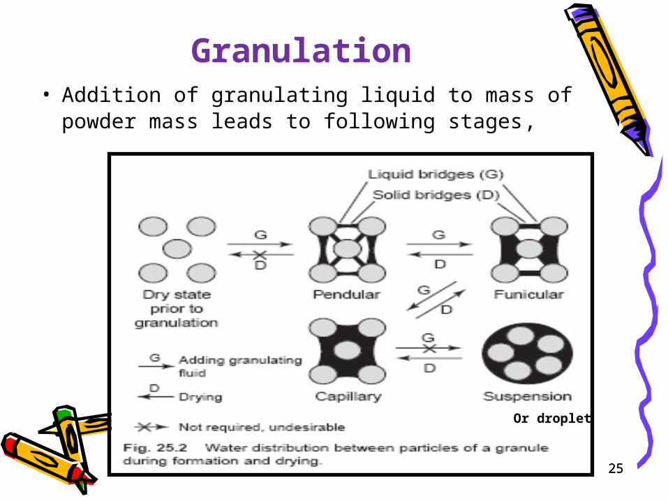
Granulation• Addition of granulating liquid to mass of powder mass leads to
following stages,
Or droplet
25
26
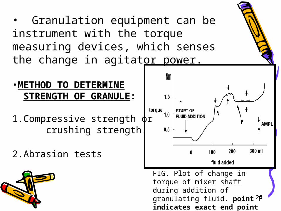
FIG. Plot of change in torque of mixer shaft during addition of granulating fluid. point F indicates exact end point to wet massing
• Granulation equipment can be instrument with the torque measuring devices, which senses the change in agitator power. •METHOD TO DETERMINE STRENGTH OF GRANULE: 1.Compressive strength or crushing strength.
2.Abrasion tests
26
27
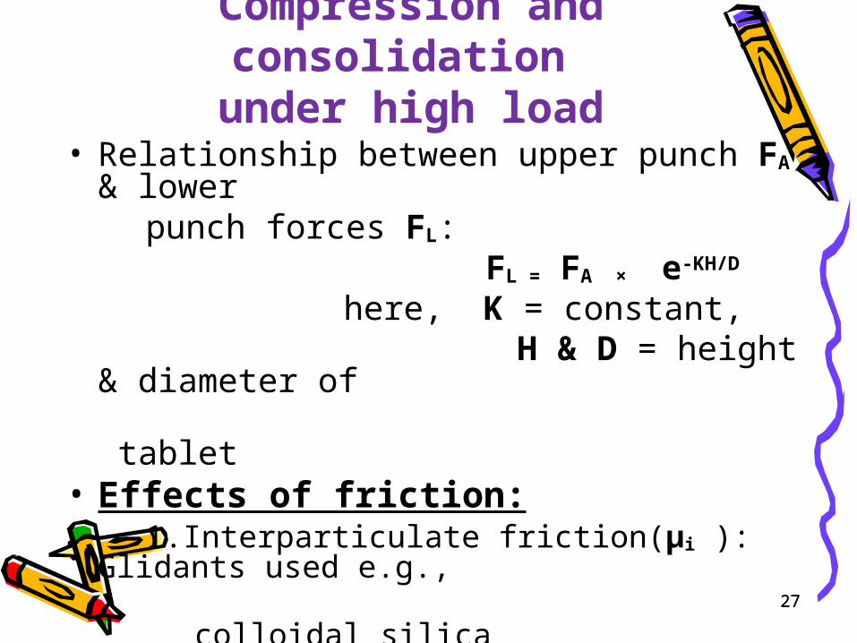
Compression and consolidation under high load
• Relationship between upper punch FA & lower punch forces FL: FL = FA × e-KH/D
here, K = constant, H & D = height & diameter of tablet• Effects of friction: 1.Interparticulate friction(μi ): Glidants used e.g., colloidal silica 2.Die-wall friction(μw ): lubricants used e.g., magnesium stearate
27
28
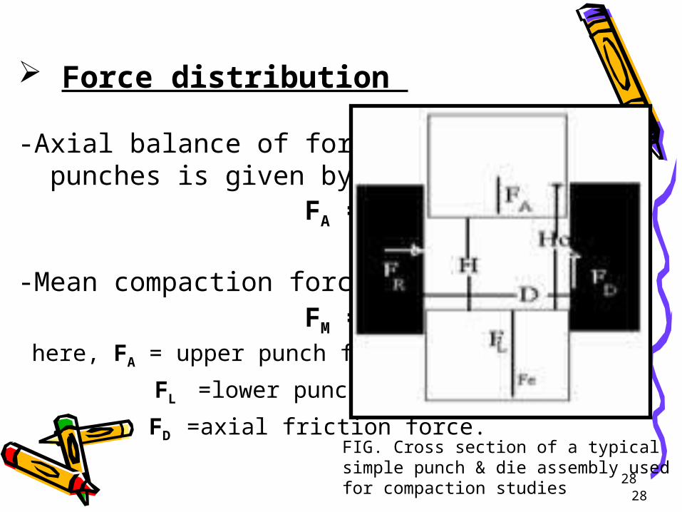
Force distribution -Axial balance of forces in punches is given by, FA = FL+FD
-Mean compaction force (FM), FM = FA+FL/ 2 here, FA = upper punch force,
FL =lower punch force,
FD =axial friction force.
28
FIG. Cross section of a typical simple punch & die assembly used for compaction studies
29
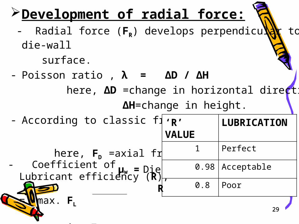
Development of radial force: - Radial force (FR) develops perpendicular to die-wall
surface.- Poisson ratio , λ = ∆D / ∆H
here, ∆D =change in horizontal direction,
∆H=change in height.- According to classic friction theory,
FD = μw × FR
here, FD =axial friction force.
μw = Die-wall friction
‘R’ VALUE
LUBRICATION
1 Perfect
0.98 Acceptable
0.8 Poor
- Coefficient of Lubricant efficiency (R),
R = max. FL
min. FA29
30
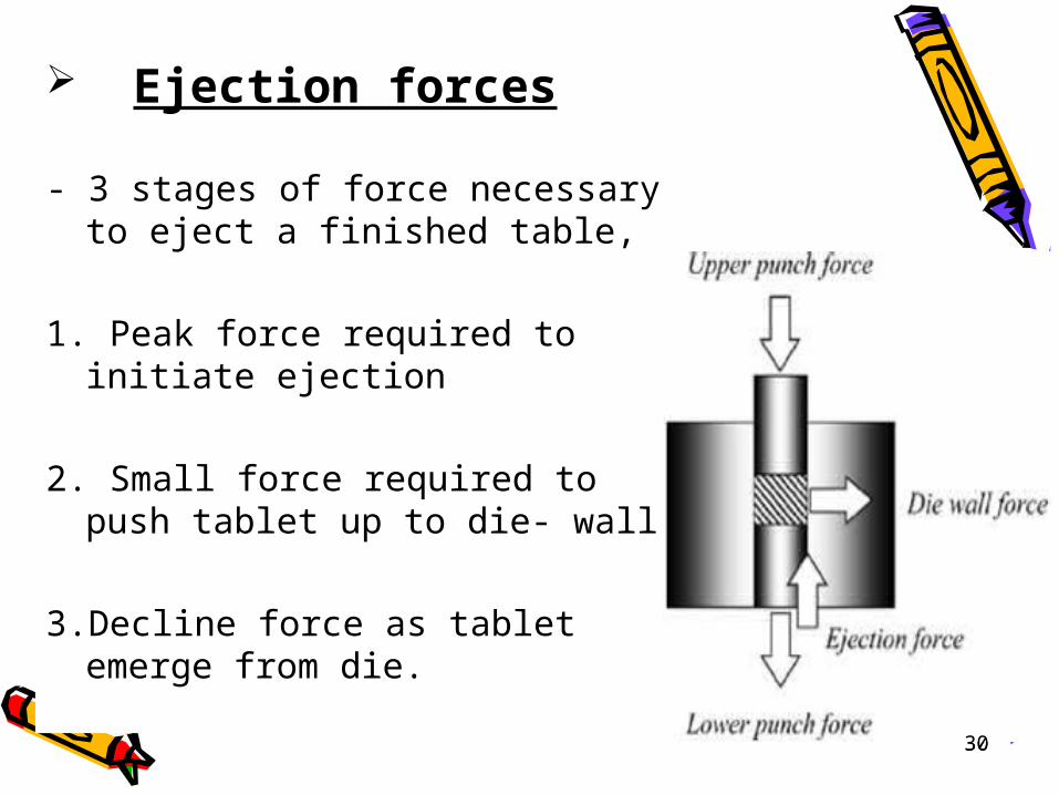
Ejection forces
- 3 stages of force necessary to eject a finished table,
1. Peak force required to initiate ejection
2. Small force required to push tablet up to die- wall
3.Decline force as tablet emerge from die.
30
31
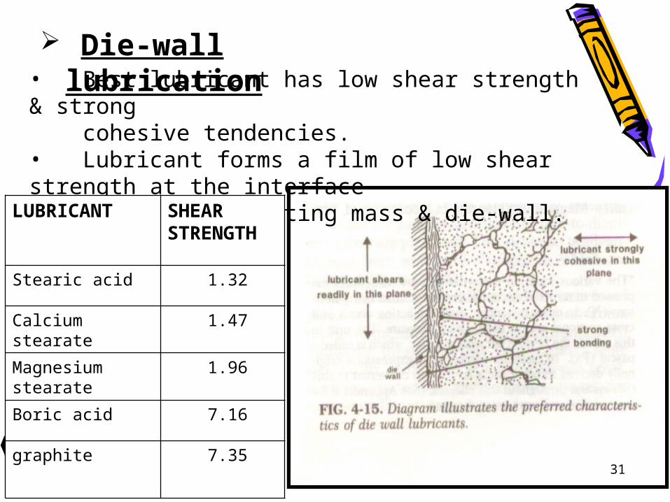
Die-wall lubrication• Best lubricant has low shear strength & strong cohesive tendencies.• Lubricant forms a film of low shear strength at the interface between tabletting mass & die-wall.
LUBRICANT SHEAR STRENGTH
Stearic acid 1.32
Calcium stearate 1.47
Magnesium stearate 1.96
Boric acid 7.16
graphite 7.35
31
32
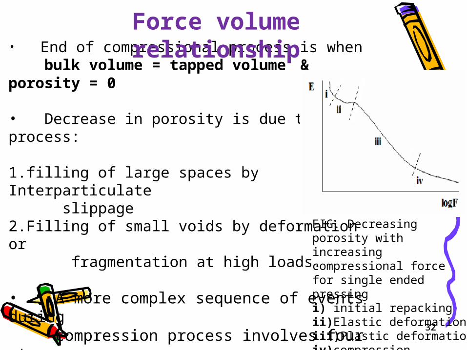
• End of compressional process is when bulk volume = tapped volume & porosity = 0 • Decrease in porosity is due to two process:
1.filling of large spaces by Interparticulate slippage2.Filling of small voids by deformation or fragmentation at high loads.
• A more complex sequence of events during compression process involves four stage as shown in fig.,
FIG. Decreasing porosity with increasing compressional force for single ended pressing i) initial repackingii)Elastic deformationiii)Plastic deformationiv)compression
Force volume relationship
32
33
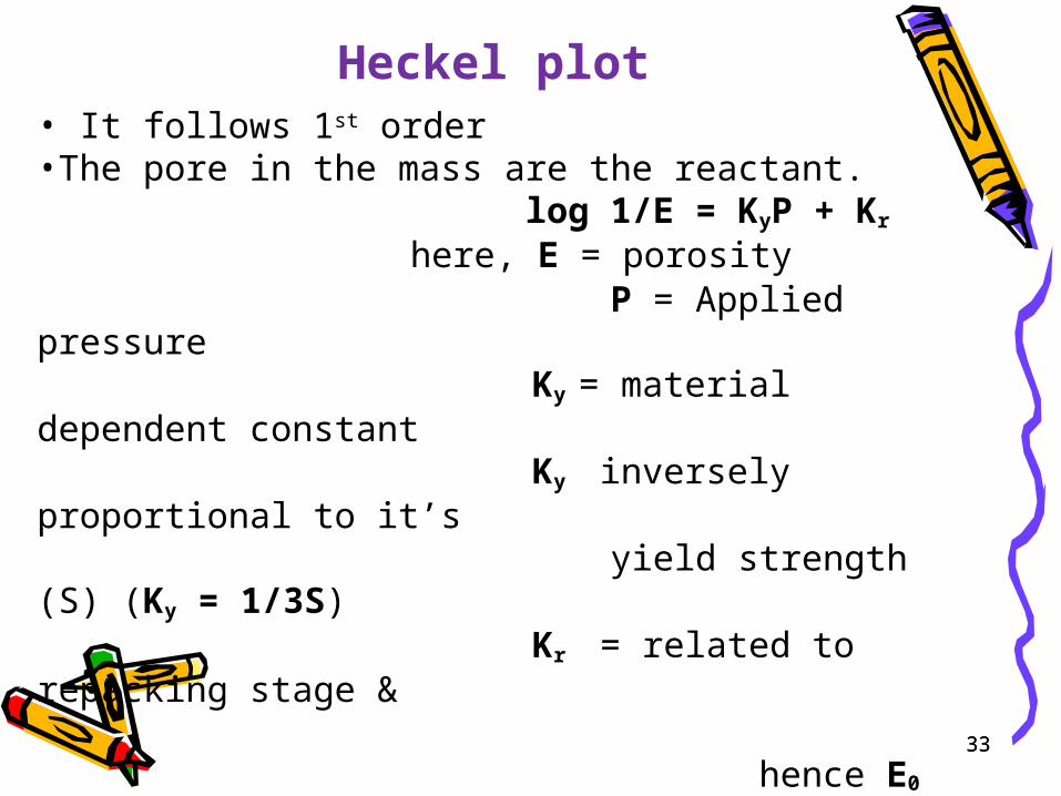
Heckel plot• It follows 1st order•The pore in the mass are the reactant. log 1/E = KyP + Kr
here, E = porosity P = Applied pressure Ky = material dependent constant
Ky inversely proportional to it’s yield strength (S) (Ky = 1/3S)
Kr = related to repacking stage & hence E0
• For cylindrical tablet, P = 4F / ∏×D2
here, P = applied pressure D = tablet diameter F = applied compressional force
33
34
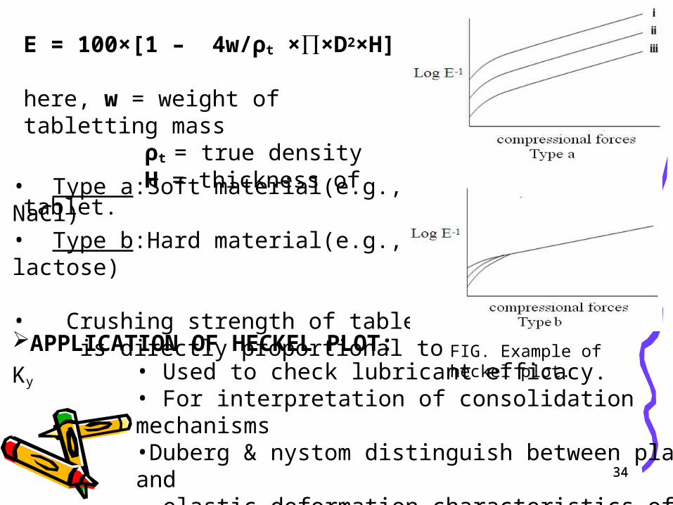
E = 100×[1 – 4w/ρt ×∏×D2×H]
here, w = weight of tabletting mass ρt = true density H = thickness of tablet.
• Type a:Soft material(e.g., NaCl)• Type b:Hard material(e.g., lactose) • Crushing strength of tablet is directly proportional to Ky
APPLICATION OF HECKEL PLOT:• Used to check lubricant efficacy.• For interpretation of consolidation mechanisms•Duberg & nystom distinguish between plastic and elastic deformation characteristics of a material.
34
FIG. Example of heckel plot.
35
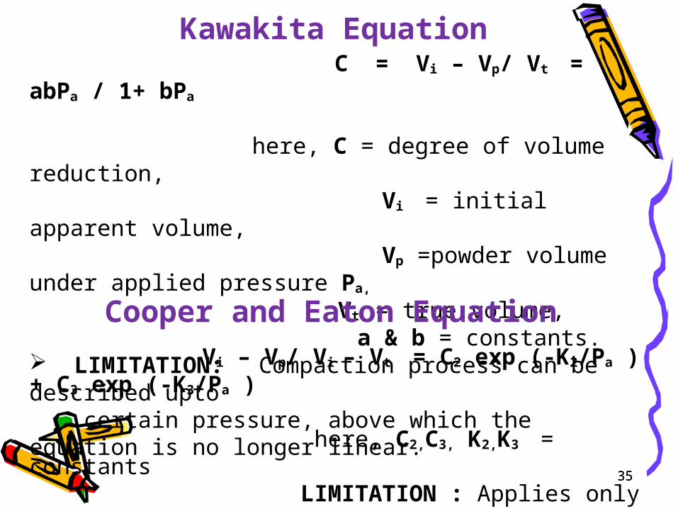
Kawakita Equation C = Vi – Vp/ Vt = abPa / 1+ bPa
here, C = degree of volume reduction, Vi = initial apparent volume, Vp =powder volume under applied pressure Pa,
Vt = true volume, a & b = constants. LIMITATION: Compaction process can be described upto certain pressure, above which the equation is no longer linear.
Vi – Vp/ Vi – Vt = C2 exp (-K2/Pa ) + C3 exp (-K3/Pa ) here, C2,C3, K2,K3 = constants LIMITATION : Applies only to single component system.
Cooper and Eaton Equation
35
36
Decompression
• Occurs on removal of applied force after compression.• Tablet must mechanically strong to withstand stresses produce during decompression.• Plastoelasticity(γ), γ = [Ho / Hm - (Hr-Hm) / Ho - Hm] here, Ho ,Hm, Hr = thickness of tablet mass at onset of loading, at max. applied pressure & on ejection from die
• γ > 9 produce tablets that are laminated or capped.
36
37
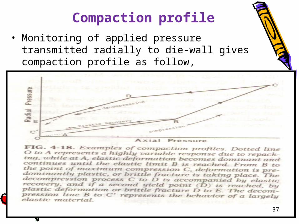
Compaction profile
• Monitoring of applied pressure transmitted radially to die-wall gives compaction profile as follow,
37
38
Energy involved in compaction• Tablet machine, roll compactor, extruder requires high input of mechanical work
• Work involve in various phases of compaction are, 1.To overcome interparticulate friction 2.To overcome friction between machine parts and particles 3.To induce deformation 4.For brittle fracture 5.Mechanical operation of various machine parts
• Lubrication reduce energy expenditure by 75%.
38
39
REFERENCES
• Leon Lachman, Herbert A.Liberman, & Joseph kanig ,THE THEORY AND PRACTICE OF INDUSTRIAL PHARMACY, third edition.
• Herbert A.Liberman, Leon Lachman & Joseph B. Schwartz ,PHARMACEUTICAL DOSAGE FORMS, TABLETS, volume II.
• ENCYCLOPEDIA OF PHARMACEUTICAL
TECHNOLOGY, second edition,volume-3.
• C.V.Subrahmanyam ,TEXTBOOK OF PHYSICAL PHARMACEUTICS, second edition.
• Gilbert S. Banker , Christopher T. Rhodes, MODERN PHARMACEUTICS , Fourth Edition.
39

40
THANK YOU
40


![SHOCK CONSOLIDATION OF POWDERS - THEORY AND ......140 ume of the solid. A shock consolidation map for AISI 9310 steel powder has been previously reported [1]. The present shock recovery](https://img.pdfslide.net/doc/110x75/6030afbfb623c163b86e6a35/shock-consolidation-of-powders-theory-and-140-ume-of-the-solid-a-shock.jpg)


![Consolidation phenomena in laser and powder-bed …11].pdf · Consolidation phenomena in laser and powder-bed based layered manufacturing ... Selective Electron Beam Melting (EBM)](https://img.pdfslide.net/doc/110x75/5b945e0209d3f2012e8d2334/consolidation-phenomena-in-laser-and-powder-bed-11pdf-consolidation-phenomena.jpg)