Embed Size (px)
Citation preview
1
PLP Compression Dead-end & Jumper Terminal for ACSR & ACSS Conductors
MARCH 2017
Be sure to read and completely understand this procedure before applying product. Be sure to select the proper PREFORMED product before application.
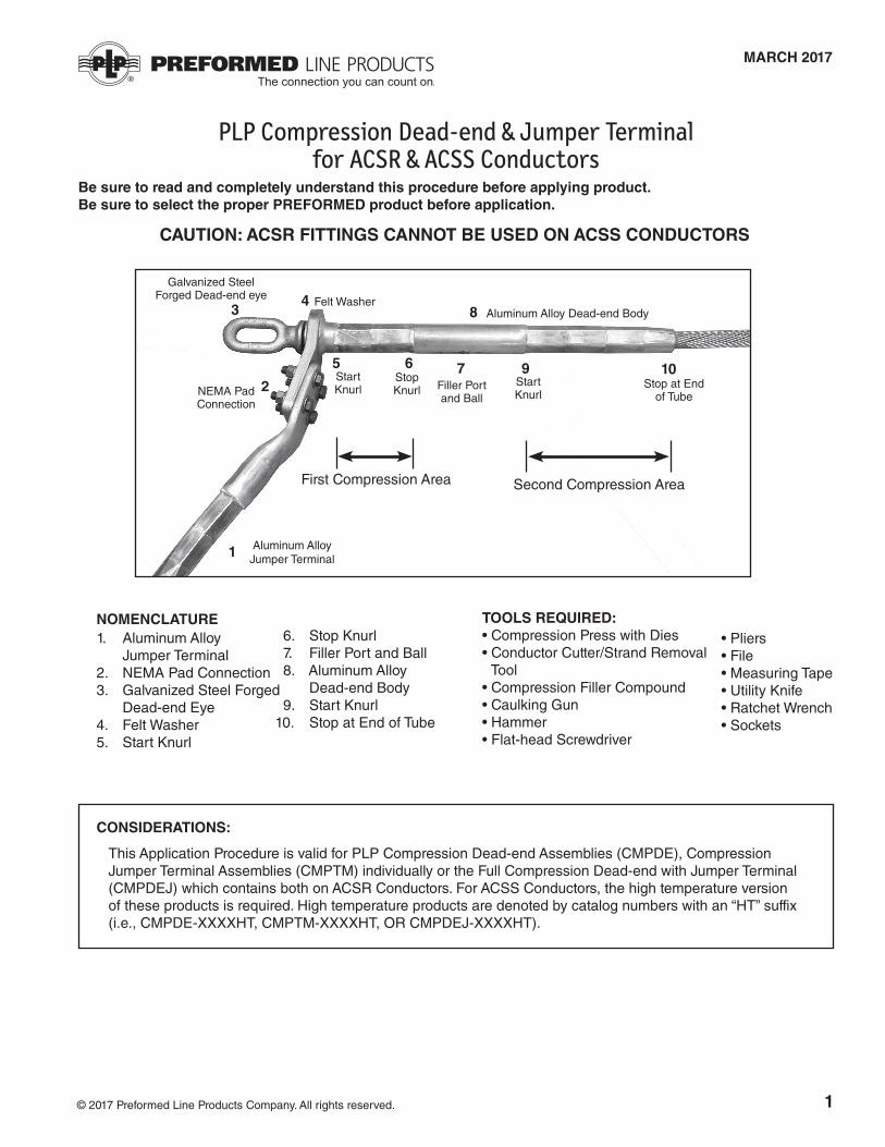
NOMENCLATURE1. Aluminum Alloy Jumper Terminal2. NEMA Pad Connection3. Galvanized Steel Forged Dead-end Eye4. Felt Washer5. Start Knurl
6. Stop Knurl 7. Filler Port and Ball 8. Aluminum Alloy Dead-end Body 9. Start Knurl10. Stop at End of Tube
2
1
34
5 6
8
7 9
First Compression Area Second Compression Area
10
• Pliers• File• Measuring Tape• Utility Knife• Ratchet Wrench• Sockets
TOOLS REQUIRED:• Compression Press with Dies• Conductor Cutter/Strand Removal
Tool• Compression Filler Compound • Caulking Gun• Hammer• Flat-head Screwdriver
CONSIDERATIONS:
Start Knurl
Stop Knurl Filler Port
and BallStart Knurl
Aluminum Alloy Dead-end BodyFelt Washer
Galvanized Steel Forged Dead-end eye
NEMA Pad Connection
Aluminum Alloy Jumper Terminal
Stop at End of Tube
CAUTION: ACSR FITTINGS CANNOT BE USED ON ACSS CONDUCTORS
© 2017 Preformed Line Products Company. All rights reserved.
This Application Procedure is valid for PLP Compression Dead-end Assemblies (CMPDE), Compression Jumper Terminal Assemblies (CMPTM) individually or the Full Compression Dead-end with Jumper Terminal (CMPDEJ) which contains both on ACSR Conductors. For ACSS Conductors, the high temperature version of these products is required. High temperature products are denoted by catalog numbers with an “HT” suffix (i.e., CMPDE-XXXXHT, CMPTM-XXXXHT, OR CMPDEJ-XXXXHT).
2
PRECAUTIONARY MEASURES:
CAUTION: BEFORE INSTALLING ANY PRODUCTS, THE FOLLOWING PRECAUTIONS MUST BE TAKEN:1. Ensure that the correct compression product has been selected for the conductor. Compare catalog numbers of the product with associated conductor size/range published in PLP literature.2. Be certain that dies being used to compress the fittings match the engraved sizes marked on the product surfaces. NOTE: Dies will have markings on the surface of the die face or the edges of the die.3. The compression press and dies MUST be inspected before use. Ensure that they are well lubricated, there are no hydraulic oil leaks, the press is of the correct size (60 or 100 Ton) to adequately compress the fittings, die surfaces mate completely when the press is fully extended, and that the dies are in good condition without significant damage or wear. 4. Before installation, the mating surfaces of the products to be installed, such as the inner bore of the aluminum tube, inner bore and outer surfaces of steel hardware, and NEMA Pad connections, must be inspected for surface defects, etc. If any significant irregularities exist, the products MUST be discarded or returned to PLP. DO NOT INSTALL DEFECTIVE OR DAMAGED COMPRESSION HARDWARE!NOTE: FAILURE TO FOLLOW THE PRECAUTIONS, NOTES AND STEPS CONTAINED WITHIN THIS APPLICATION PROCEDURE REPRESENTS A MISAPPLICATION OF THE PRODUCT! THIS PRODUCT AND APPLICATION PROCEDURE ARE FOR ACSR & ACSS CONDUCTORS ONLY.
Step #1 Begin by cleaning/wire-brushing the entire area to be covered by the compression hardware per your standard company practices. Check that no residue or surface particles remain.
DEAD-END ASSEMBLY APPLICATION
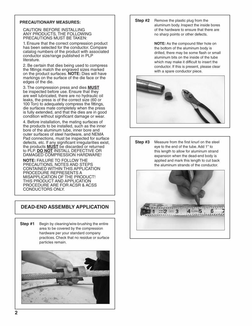
Step #3 Measure from the first knurl on the steel eye to the end of the tube. Add 1" to this length to allow for aluminum strand expansion when the dead-end body is applied and mark this length to cut back the aluminum strands of the conductor.
Step #2 Remove the plastic plug from the aluminum body. Inspect the inside bores of the hardware to ensure that there are no sharp points or other defects. NOTE: As the compound filler hole on the bottom of the aluminum body is drilled, there may be some flash or small aluminum bits on the inside of the tube which may make it difficult to insert the conductor. If this is present, please clear with a spare conductor piece.
3
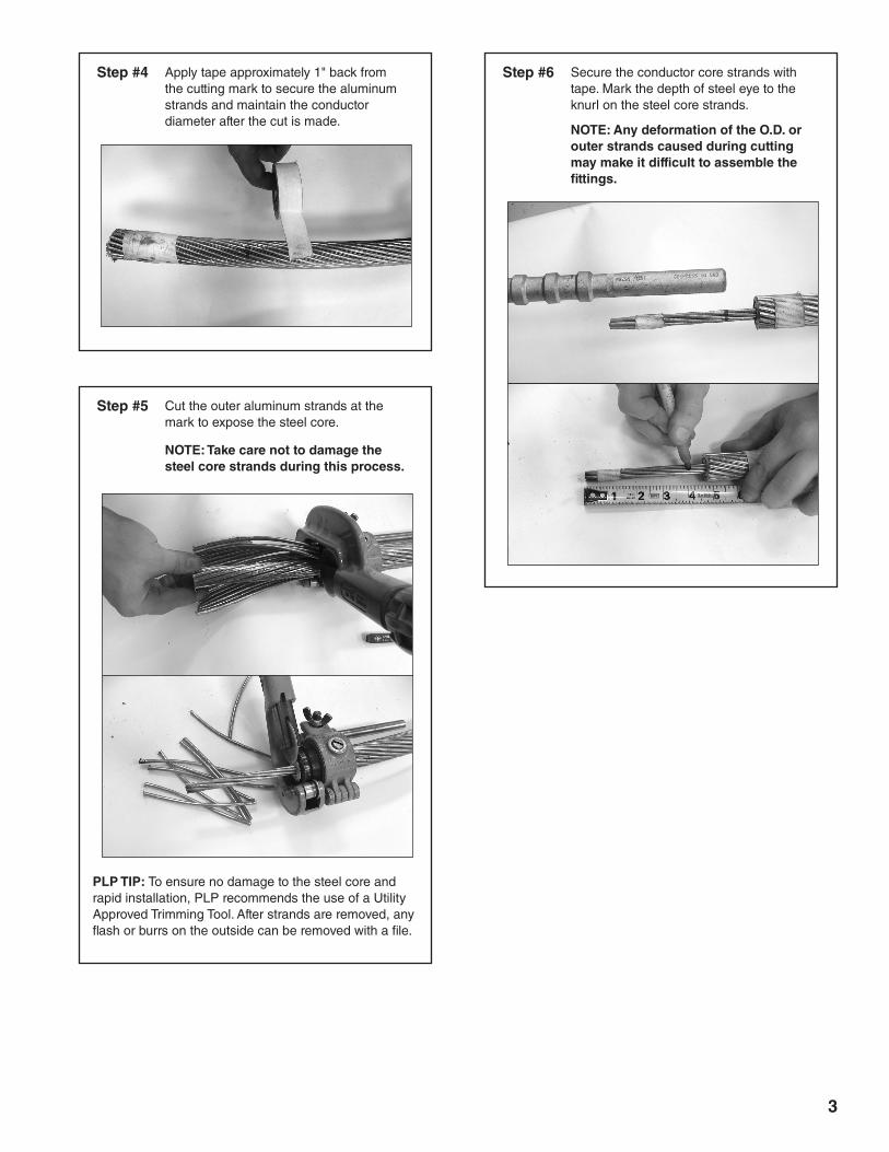
Step #4 Apply tape approximately 1" back from the cutting mark to secure the aluminum strands and maintain the conductor diameter after the cut is made.
Step #5 Cut the outer aluminum strands at the mark to expose the steel core.
NOTE: Take care not to damage the steel core strands during this process.
PLP TIP: To ensure no damage to the steel core and rapid installation, PLP recommends the use of a Utility Approved Trimming Tool. After strands are removed, any flash or burrs on the outside can be removed with a file.
Step #6 Secure the conductor core strands with tape. Mark the depth of steel eye to the knurl on the steel core strands. NOTE: Any deformation of the O.D. or outer strands caused during cutting may make it difficult to assemble the fittings.
4
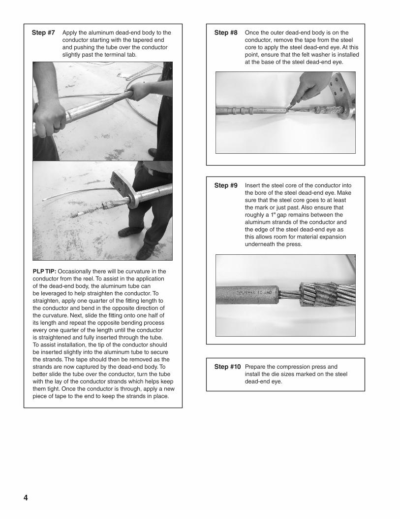
Step #7 Apply the aluminum dead-end body to the conductor starting with the tapered end and pushing the tube over the conductor slightly past the terminal tab.
PLP TIP: Occasionally there will be curvature in the conductor from the reel. To assist in the application of the dead-end body, the aluminum tube can be leveraged to help straighten the conductor. To straighten, apply one quarter of the fitting length to the conductor and bend in the opposite direction of the curvature. Next, slide the fitting onto one half of its length and repeat the opposite bending process every one quarter of the length until the conductor is straightened and fully inserted through the tube. To assist installation, the tip of the conductor should be inserted slightly into the aluminum tube to secure the strands. The tape should then be removed as the strands are now captured by the dead-end body. To better slide the tube over the conductor, turn the tube with the lay of the conductor strands which helps keep them tight. Once the conductor is through, apply a new piece of tape to the end to keep the strands in place.
Step #8 Once the outer dead-end body is on the conductor, remove the tape from the steel core to apply the steel dead-end eye. At this point, ensure that the felt washer is installed at the base of the steel dead-end eye.
Step #9 Insert the steel core of the conductor into the bore of the steel dead-end eye. Make sure that the steel core goes to at least the mark or just past. Also ensure that roughly a 1" gap remains between the aluminum strands of the conductor and the edge of the steel dead-end eye as this allows room for material expansion underneath the press.
Step #10 Prepare the compression press and install the die sizes marked on the steel dead-end eye.
5
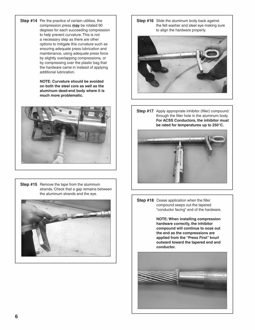
Step #12 Insert the assembly into the compression press. Ensure the proper alignment of the steel eye with the compression dead-end body.
Step #13Starting at the “Press First” knurl, compress the steel eye onto the steel conductor core, applying compressions first at the knurl and working out towards the conductor.
NOTE: FULL COMPRESSIONS (WITH THE DIES PUSHED TO THEIR MAXIMUM EXTENT IN THE PRESS) MUST BE APPLIED TO THE ENTIRE PORTION OF THE STEEL EYE FROM THE KNURL ALL THE WAY TO THE END. FAILURE TO APPLY FULL COMPRESSIONS TO THE ENTIRE PORTION OF THE STEEL EYE FROM KNURL TO END REPRESENTS A MISAPPLICATION OF THE PRODUCT!
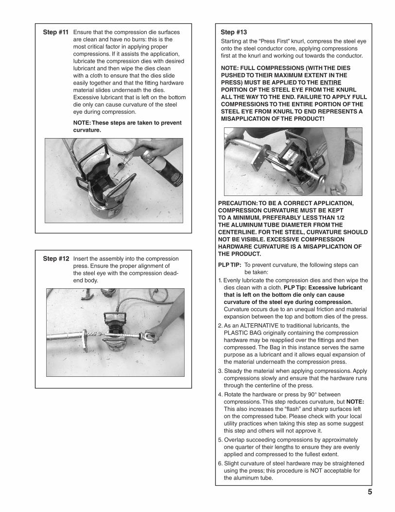
Step #11 Ensure that the compression die surfaces are clean and have no burrs: this is the most critical factor in applying proper compressions. If it assists the application, lubricate the compression dies with desired lubricant and then wipe the dies clean with a cloth to ensure that the dies slide easily together and that the fitting hardware material slides underneath the dies. Excessive lubricant that is left on the bottom die only can cause curvature of the steel eye during compression.
NOTE: These steps are taken to prevent curvature.
PRECAUTION: TO BE A CORRECT APPLICATION, COMPRESSION CURVATURE MUST BE KEPT TO A MINIMUM, PREFERABLY LESS THAN 1/2 THE ALUMINUM TUBE DIAMETER FROM THE CENTERLINE. FOR THE STEEL, CURVATURE SHOULD NOT BE VISIBLE. EXCESSIVE COMPRESSION HARDWARE CURVATURE IS A MISAPPLICATION OF THE PRODUCT.
PLP TIP: To prevent curvature, the following steps can be taken:1. Evenly lubricate the compression dies and then wipe the
dies clean with a cloth. PLP Tip: Excessive lubricant that is left on the bottom die only can cause curvature of the steel eye during compression. Curvature occurs due to an unequal friction and material expansion between the top and bottom dies of the press.
2. As an ALTERNATIVE to traditional lubricants, the PLASTIC BAG originally containing the compression hardware may be reapplied over the fittings and then compressed. The Bag in this instance serves the same purpose as a lubricant and it allows equal expansion of the material underneath the compression press.
3. Steady the material when applying compressions. Apply compressions slowly and ensure that the hardware runs through the centerline of the press.
4. Rotate the hardware or press by 90° between compressions. This step reduces curvature, but NOTE: This also increases the “flash” and sharp surfaces left on the compressed tube. Please check with your local utility practices when taking this step as some suggest this step and others will not approve it.
5. Overlap succeeding compressions by approximately one quarter of their lengths to ensure they are evenly applied and compressed to the fullest extent.
6. Slight curvature of steel hardware may be straightened using the press; this procedure is NOT acceptable for the aluminum tube.
6
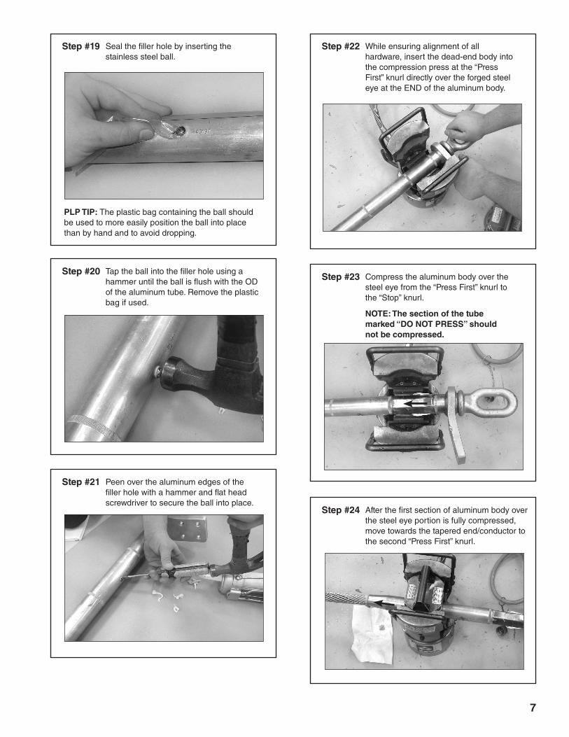
Step #16 Slide the aluminum body back against the felt washer and steel eye making sure to align the hardware properly.
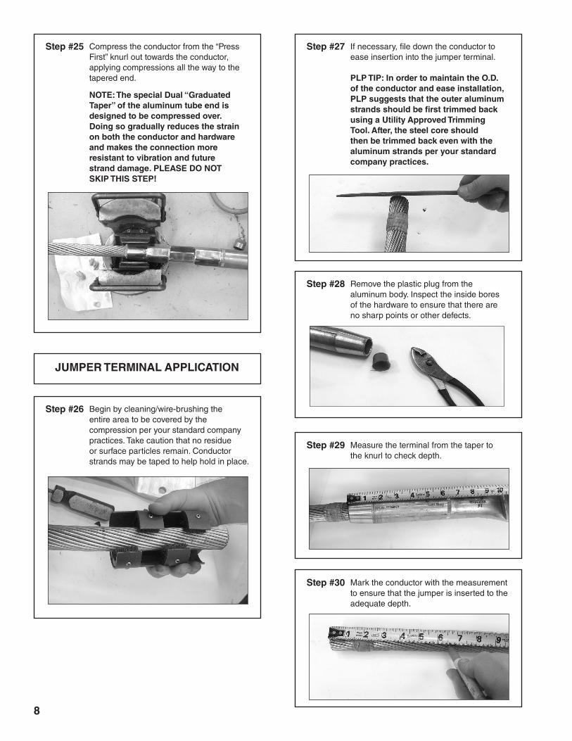
Step #17 Apply appropriate inhibitor (filler) compound through the filler hole in the aluminum body. For ACSS Conductors, the inhibitor must be rated for temperatures up to 250°C.
Step #18 Cease application when the filler compound seeps out the tapered “conductor facing” end of the hardware.
NOTE: When installing compression hardware correctly, the inhibitor compound will continue to ooze out the end as the compressions are applied from the “Press First” knurl outward toward the tapered end and conductor.
Step #15 Remove the tape from the aluminum strands. Check that a gap remains between the aluminum strands and the eye.
Step #14 Per the practice of certain utilities, the compression press may be rotated 90 degrees for each succeeding compression to help prevent curvature. This is not a necessary step as there are other options to mitigate this curvature such as ensuring adequate press lubrication and maintenance, using adequate press force by slightly overlapping compressions, or by compressing over the plastic bag that the hardware came in instead of applying additional lubrication.
NOTE: Curvature should be avoided on both the steel core as well as the aluminum dead-end body where it is much more problematic.
7
Step #19 Seal the filler hole by inserting the stainless steel ball.
PLP TIP: The plastic bag containing the ball should be used to more easily position the ball into place than by hand and to avoid dropping.
Step #20 Tap the ball into the filler hole using a hammer until the ball is flush with the OD of the aluminum tube. Remove the plastic bag if used.
Step #21 Peen over the aluminum edges of the filler hole with a hammer and flat head screwdriver to secure the ball into place.
Step #22 While ensuring alignment of all hardware, insert the dead-end body into the compression press at the “Press First” knurl directly over the forged steel eye at the END of the aluminum body.
Step #23 Compress the aluminum body over the steel eye from the “Press First” knurl to the “Stop” knurl.
NOTE: The section of the tube marked “DO NOT PRESS” should not be compressed.
Step #24 After the first section of aluminum body over the steel eye portion is fully compressed, move towards the tapered end/conductor to the second “Press First” knurl.
8
Step #25 Compress the conductor from the “Press First” knurl out towards the conductor, applying compressions all the way to the tapered end.
NOTE: The special Dual “Graduated Taper” of the aluminum tube end is designed to be compressed over. Doing so gradually reduces the strain on both the conductor and hardware and makes the connection more resistant to vibration and future strand damage. PLEASE DO NOT SKIP THIS STEP!
JUMPER TERMINAL APPLICATION
Step #26 Begin by cleaning/wire-brushing the entire area to be covered by the compression per your standard company practices. Take caution that no residue or surface particles remain. Conductor strands may be taped to help hold in place.
Step #27 If necessary, file down the conductor to ease insertion into the jumper terminal.
PLP TIP: In order to maintain the O.D. of the conductor and ease installation, PLP suggests that the outer aluminum strands should be first trimmed back using a Utility Approved Trimming Tool. After, the steel core should then be trimmed back even with the aluminum strands per your standard company practices.
Step #29 Measure the terminal from the taper to the knurl to check depth.
Step #30 Mark the conductor with the measurement to ensure that the jumper is inserted to the adequate depth.
Step #28 Remove the plastic plug from the aluminum body. Inspect the inside bores of the hardware to ensure that there are no sharp points or other defects.
9
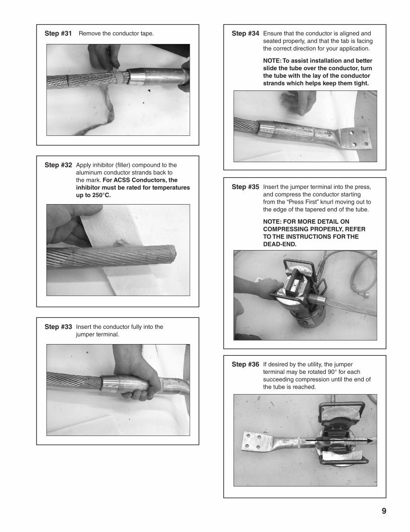
Step #31 Remove the conductor tape.
Step #32 Apply inhibitor (filler) compound to the aluminum conductor strands back to the mark. For ACSS Conductors, the inhibitor must be rated for temperatures up to 250°C.
Step #33 Insert the conductor fully into the jumper terminal.
Step #34 Ensure that the conductor is aligned and seated properly, and that the tab is facing the correct direction for your application.
NOTE: To assist installation and better slide the tube over the conductor, turn the tube with the lay of the conductor strands which helps keep them tight.
Step #35 Insert the jumper terminal into the press, and compress the conductor starting from the “Press First” knurl moving out to the edge of the tapered end of the tube.
NOTE: FOR MORE DETAIL ON COMPRESSING PROPERLY, REFER TO THE INSTRUCTIONS FOR THE DEAD-END.
Step #36 If desired by the utility, the jumper terminal may be rotated 90° for each succeeding compression until the end of the tube is reached.
10
FULL DEAD-END ASSEMBLY APPLICATION
Step #37
Step #38
Check once again to ensure that the pad connections are free from damage and any residue has been removed. Thoroughly wire brush the pads of both the dead-end and the jumper to ensure that oxidation build up is removed.
Coat the dead-end terminal pad with conductive electrical joint compound. Spread the compound evenly over the pad to ensure total coverage.
Do not use the inhibitor (filler) compound that is used to fill the compression dead-end before compressions.
Step #39 To install the jumper terminal pad to the compression dead-end pad and complete the full dead-end assembly, insert a flat washer onto each bolt and thread through the pad. On the opposite end, apply the other flat washer, then lockwasher, then nut, and hand tighten. Once tight, torque bolts to at least 40 ft-lbs, revisiting each bolt several times to ensure that the pad is fully compressed and that all bolts are tightened to the proper specification.
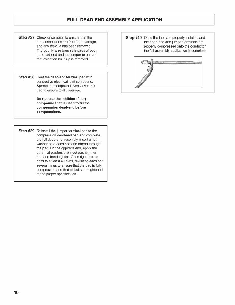
Step #40 Once the tabs are properly installed and the dead-end and jumper terminals are properly compressed onto the conductor, the full assembly application is complete.

11

12
SP3125-3
P.O. Box 91129, Cleveland, Ohio 44101 • 440.461.5200 • www.preformed.com • e-mail: [email protected]
SAFETY CONSIDERATIONS
This application procedure is not intended to supersede any company construction or safety standards. This procedure is offered only to illustrate safe application for the individual. FAILURE TO FOLLOW THESE PROCEDURES MAY RESULT IN PERSONAL INJURY OR DEATH.
This product is intended for a single (one time) use and for the specified application. Do not reuse or modify this product under any circumstances.
This product is intended for use by trained technicians only. This product should not be used by anyone who is not familiar with, and not trained to use it.
When working in the area of energized lines, extra care should be taken to prevent accidental electrical contact.
For proper performance and personal safety, be sure to select the proper size PREFORMEDTM product before application.
PREFORMED products are precision devices. To insure proper performance, they should be stored in cartons under cover and handled carefully.


![Untitled-1 [preformed.com]preformed.com/images/pdfs/Communications/Fiber_Networks/...Buffer Tube Retainer Clips Shell Supporters (not shown) Splice Tray Splice Retainer Block Splice](https://img.pdfslide.net/doc/110x75/60ec7b50d1427246717b3904/untitled-1-buffer-tube-retainer-clips-shell-supporters-not-shown-splice.jpg)