Embed Size (px)
Citation preview
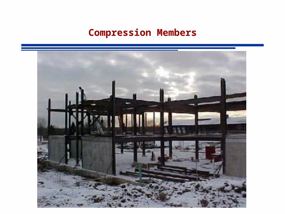
Compression Members
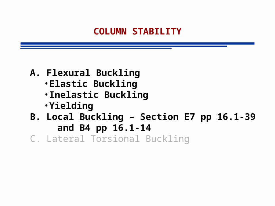
COLUMN STABILITY
A. Flexural Buckling• Elastic Buckling• Inelastic Buckling• Yielding
B. Local Buckling – Section E7 pp 16.1-39 and B4 pp 16.1-14
C. Lateral Torsional Buckling
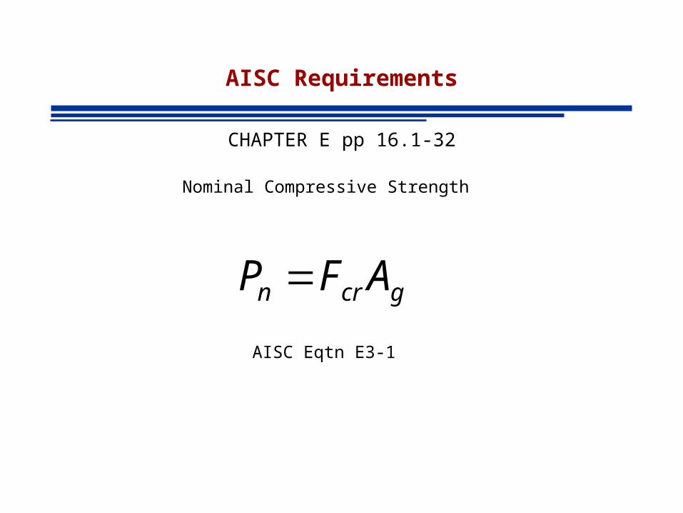
AISC Requirements
CHAPTER E pp 16.1-32
Nominal Compressive Strength
gcrn AFP
AISC Eqtn E3-1
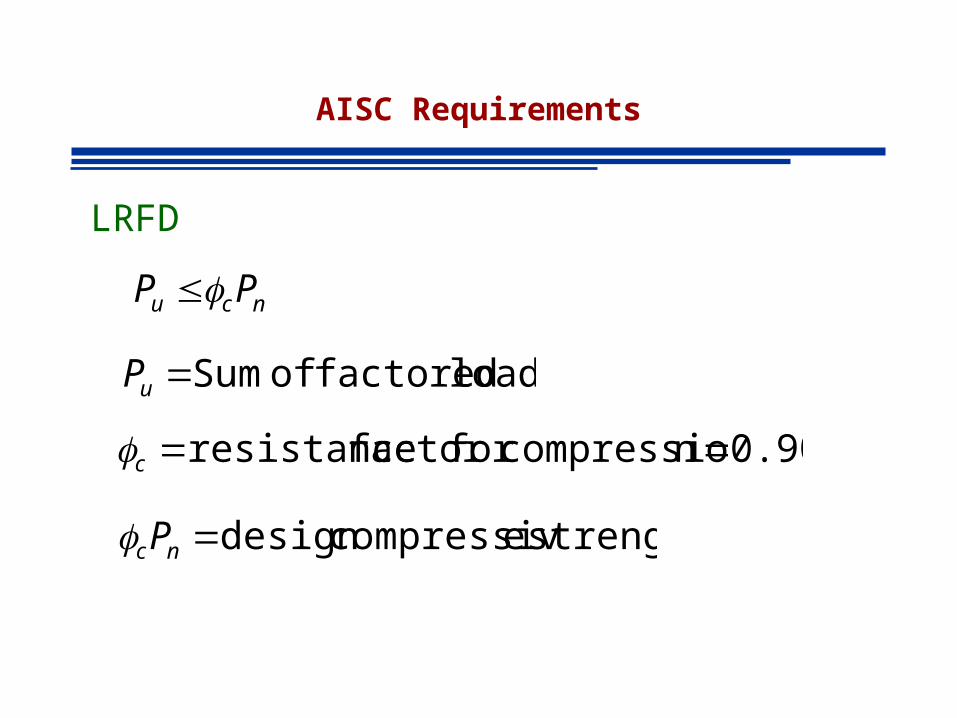
AISC Requirements
LRFD
ncu PP
loads factored of Sum uP
strength ecompressiv design ncP
0.90 ncompressiofor factor resistance c
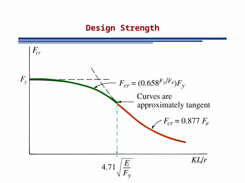
Design Strength
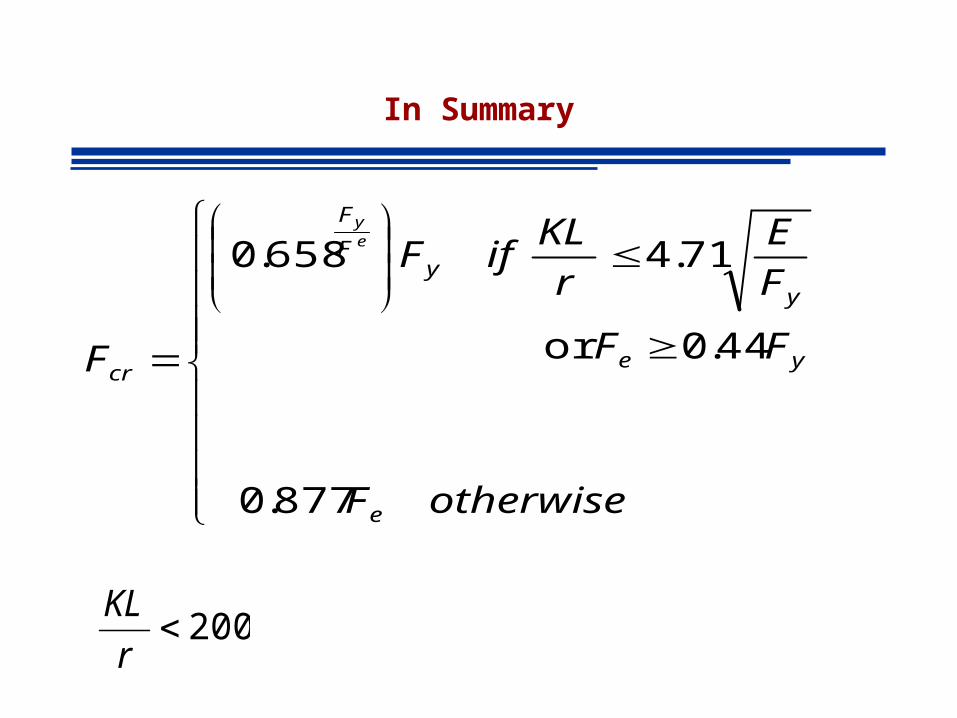
In Summary
877.0
44.0or
71.4 658.0
otherwiseF
FF
F
E
r
KLifF
F
e
ye
yy
F
F
cr
ey
200r
KL
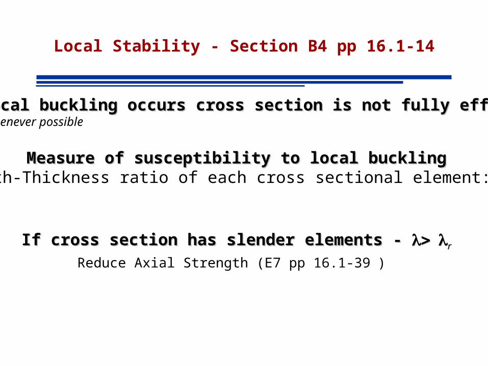
Local Stability - Section B4 pp 16.1-14
Local Stability: If elements of cross section are thin LOCAL buckling occurs
The strength corresponding to any buckling mode cannot be developed
Local Stability - Section B4 pp 16.1-14
Local Stability: If elements of cross section are thin LOCAL buckling occurs
The strength corresponding to any buckling mode cannot be developed
Local Stability - Section B4 pp 16.1-14
• Stiffened Elements of Cross-Section
• Unstiffened Elements of Cross-Section
Local Stability - Section B4 pp 16.1-14
• Compact– Section Develops its full plastic stress before buckling
(failure is due to yielding only)
• Noncompact– Yield stress is reached in some but not all of its compression elements
before buckling takes place
(failure is due to partial buckling partial yielding)
• Slender– Yield stress is never reached in any of the compression elements
(failure is due to local buckling only)
Local Stability - Section B4 pp 16.1-14
If local buckling occurs cross section is not fully effectiveIf local buckling occurs cross section is not fully effectiveAvoid whenever possible
Measure of susceptibility to local bucklingMeasure of susceptibility to local bucklingWidth-Thickness ratio of each cross sectional element:
If cross section has slender elements - If cross section has slender elements - rr
Reduce Axial Strength (E7 pp 16.1-39 )
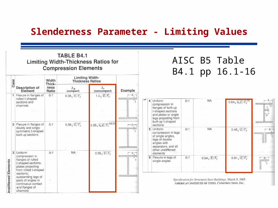
Slenderness Parameter - Limiting Values
AISC B5 Table B4.1 pp 16.1-16
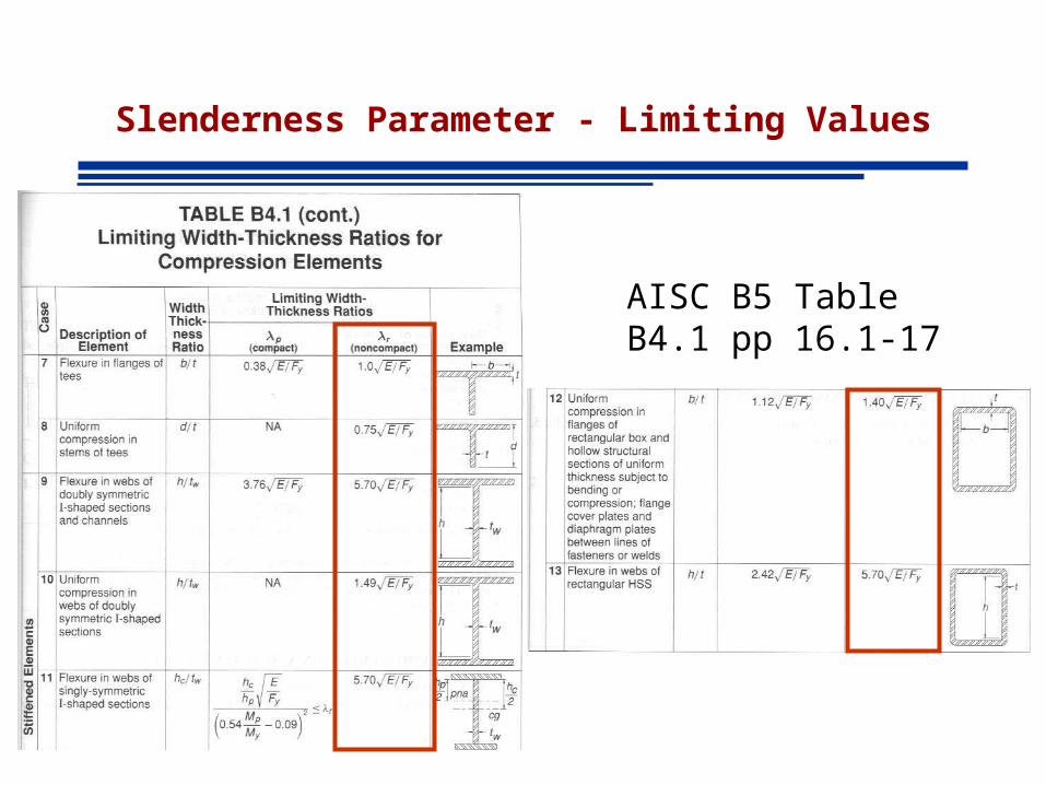
Slenderness Parameter - Limiting Values
AISC B5 Table B4.1 pp 16.1-17
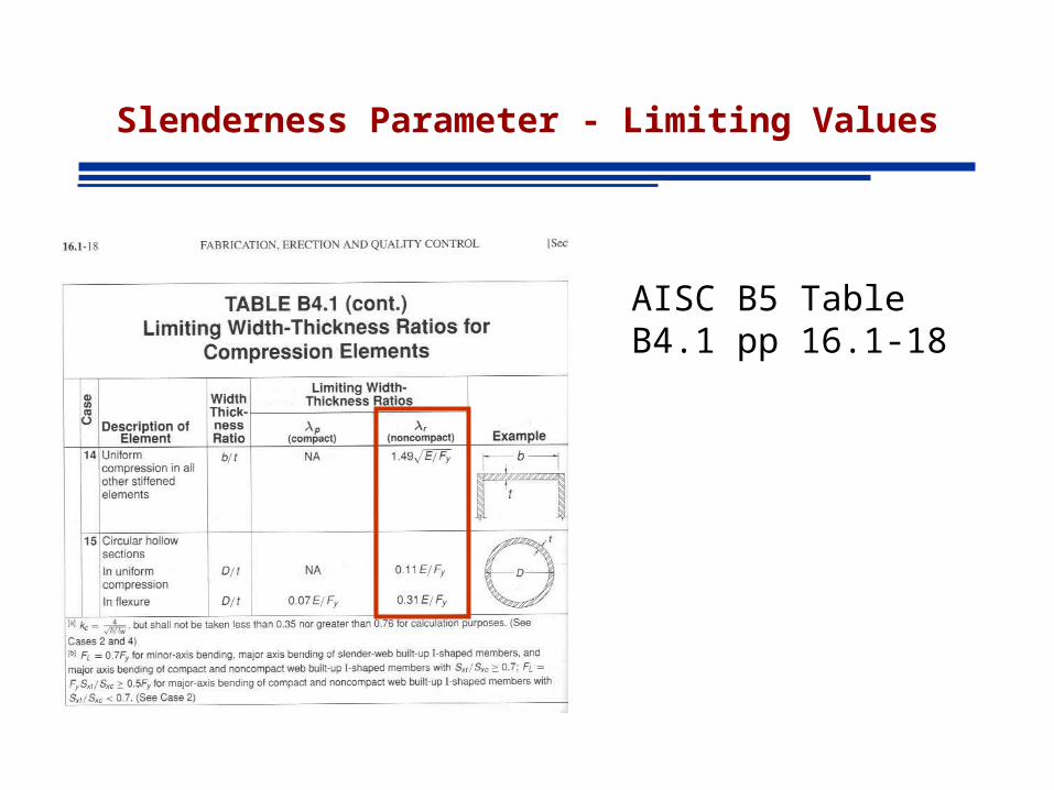
Slenderness Parameter - Limiting Values
AISC B5 Table B4.1 pp 16.1-18
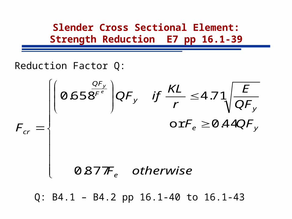
Slender Cross Sectional Element:Strength Reduction E7 pp 16.1-39
Reduction Factor Q:
Q: B4.1 – B4.2 pp 16.1-40 to 16.1-43
877.0
44.0or
71.4 658.0
otherwiseF
QFF
QF
E
r
KLifQF
F
e
ye
yy
F
QF
cr
ey
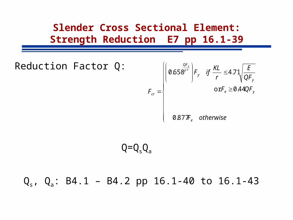
Slender Cross Sectional Element:Strength Reduction E7 pp 16.1-39
Reduction Factor Q:
Qs, Qa: B4.1 – B4.2 pp 16.1-40 to 16.1-43
877.0
44.0or
71.4 658.0
otherwiseF
QFF
QF
E
r
KLifF
F
e
ye
yy
F
QF
cr
ey
Q=QsQa
COLUMN STABILITY
A. Flexural Buckling• Elastic Buckling• Inelastic Buckling• Yielding
B. Local Buckling – Section E7 pp 16.1-39 and B4 pp 16.1-14
C. Torsional, Lateral/Torsional Buckling
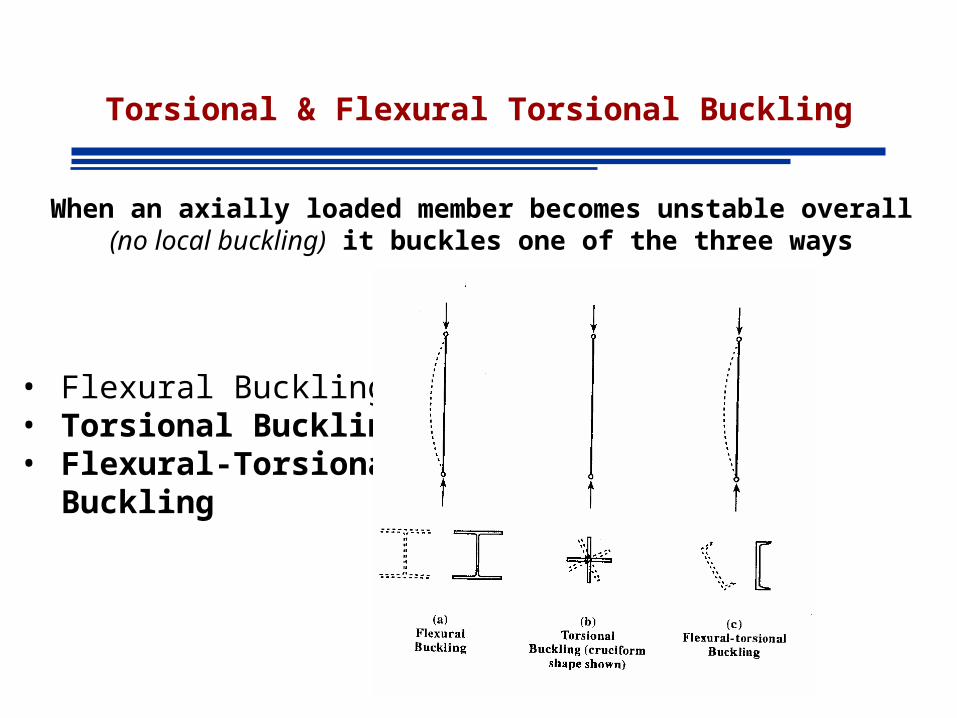
Torsional & Flexural Torsional Buckling
When an axially loaded member becomes unstable overall(no local buckling) it buckles one of the three ways
• Flexural Buckling• Torsional Buckling• Flexural-Torsional
Buckling
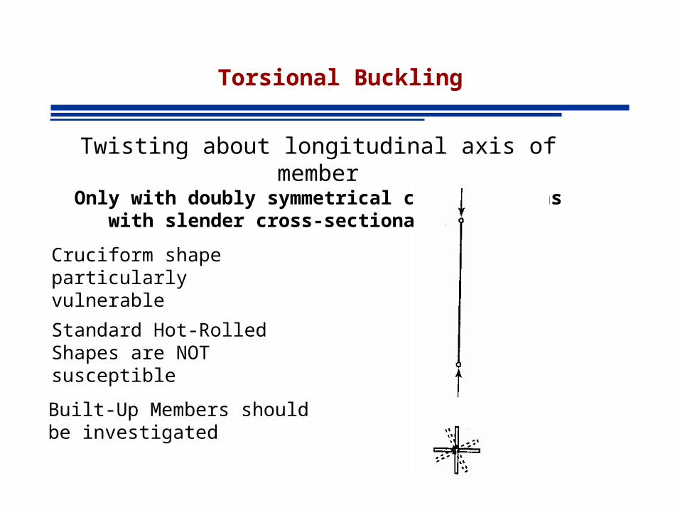
Torsional Buckling
Twisting about longitudinal axis of memberOnly with doubly symmetrical cross sections with slender cross-
sectional elements
Standard Hot-Rolled Shapes are NOT susceptible
Built-Up Members should be investigated
Cruciform shape particularly vulnerable
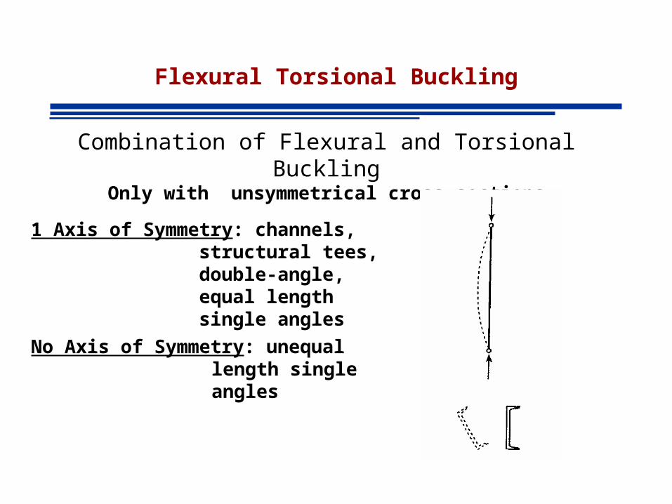
Flexural Torsional Buckling
Combination of Flexural and Torsional BucklingOnly with unsymmetrical cross sections
1 Axis of Symmetry: channels, structural tees, double-angle, equal length single angles
No Axis of Symmetry: unequal length single angles
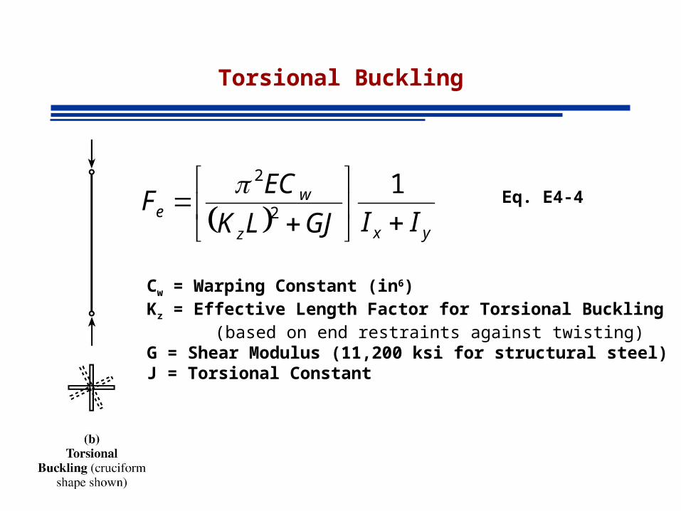
Torsional Buckling
yxz
we IIGJLK
ECF
1
2
2Eq. E4-4
Cw = Warping Constant (in6)Kz = Effective Length Factor for Torsional Buckling
(based on end restraints against twisting)G = Shear Modulus (11,200 ksi for structural steel)J = Torsional Constant
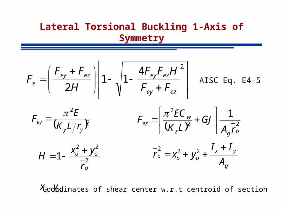
Lateral Torsional Buckling 1-Axis of Symmetry
2411
2 ezey
ezeyezeye FF
HFF
H
FFF AISC Eq. E4-5
2
2
yy
eyrLK
EF
22
2 1
ogz
wez
rAGJ
LK
ECF
2
22
1o
oo
r
yxH
g
yxooo
A
IIyxr
222
oo yx , Coordinates of shear center w.r.t centroid of section
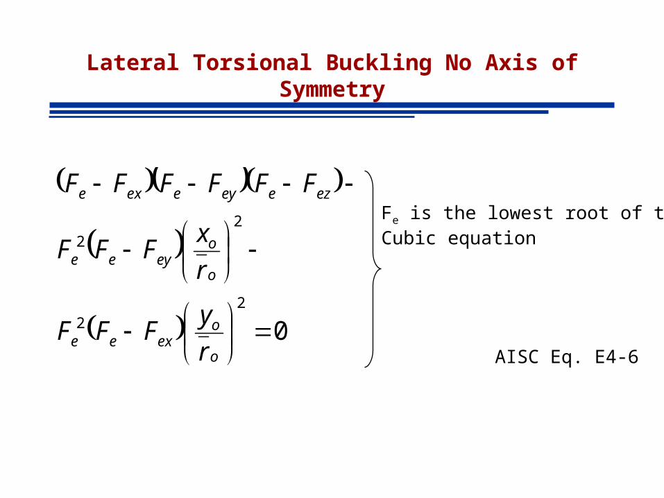
Lateral Torsional Buckling No Axis of Symmetry
02
2
22
o
oexee
o
oeyee
ezeeyeexe
r
yFFF
r
xFFF
FFFFFF
AISC Eq. E4-6
Fe is the lowest root of theCubic equation
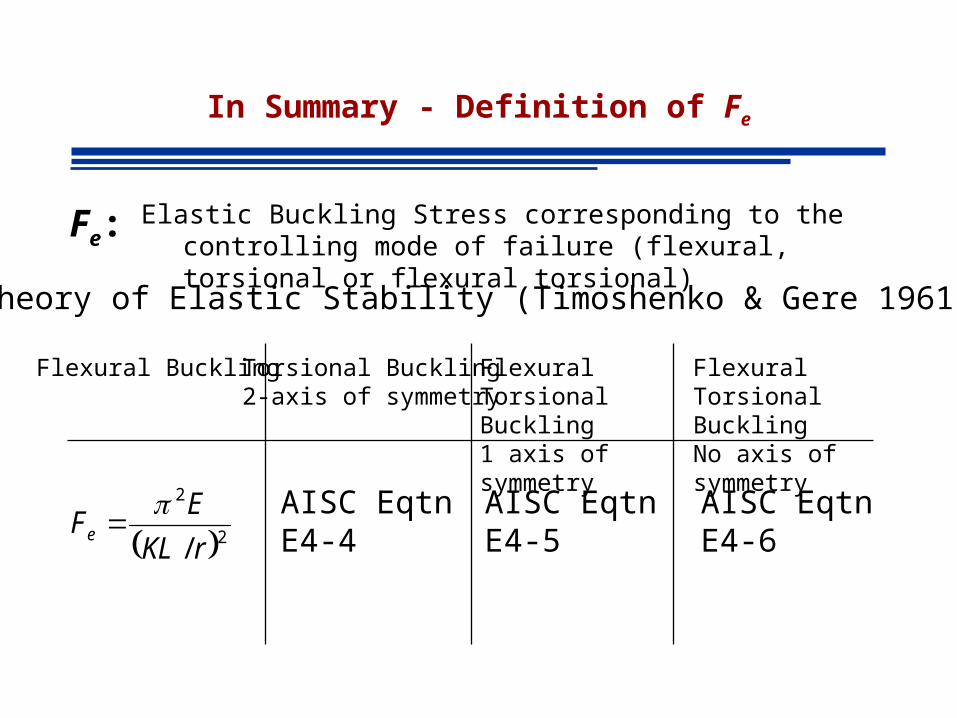
In Summary - Definition of Fe
Elastic Buckling Stress corresponding to the controlling mode of failure (flexural, torsional or flexural torsional)
Fe:
Theory of Elastic Stability (Timoshenko & Gere 1961)
Flexural Buckling Torsional Buckling2-axis of symmetry
Flexural Torsional Buckling1 axis of symmetry
Flexural Torsional BucklingNo axis of symmetry
2
2
/ rKL
EFe
AISC EqtnE4-4
AISC EqtnE4-5
AISC EqtnE4-6
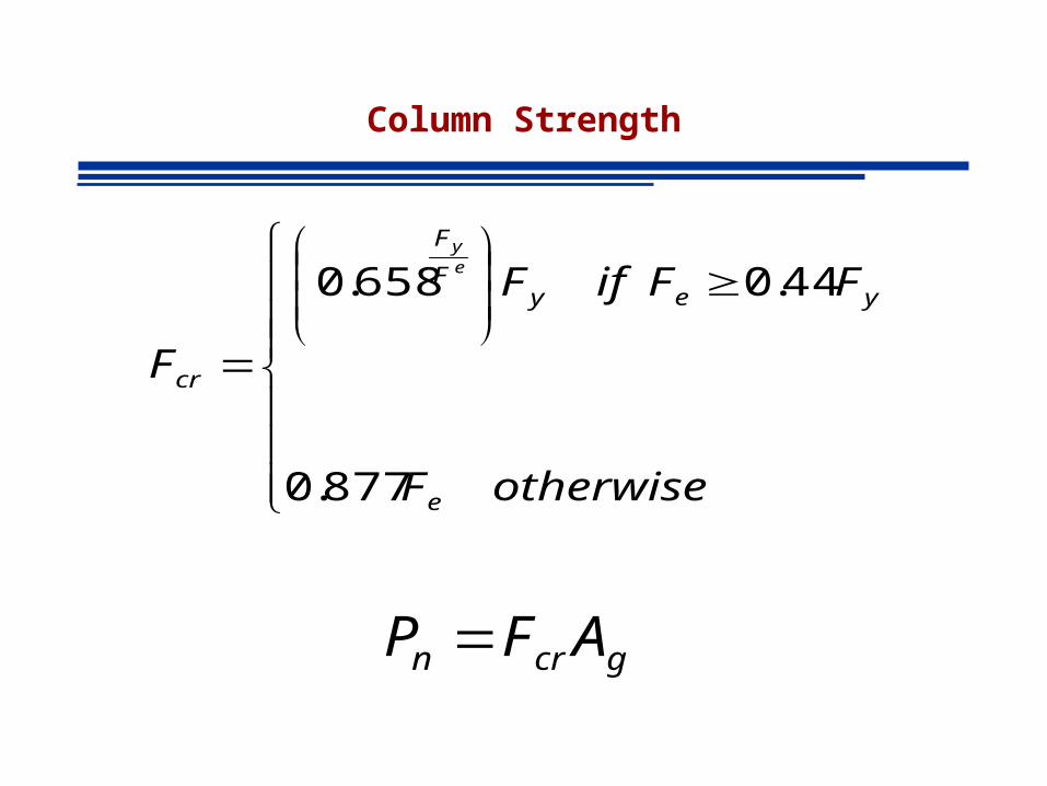
Column Strength
877.0
44.0 658.0
otherwiseF
FFifF
F
e
yeyF
F
cr
ey
gcrn AFP
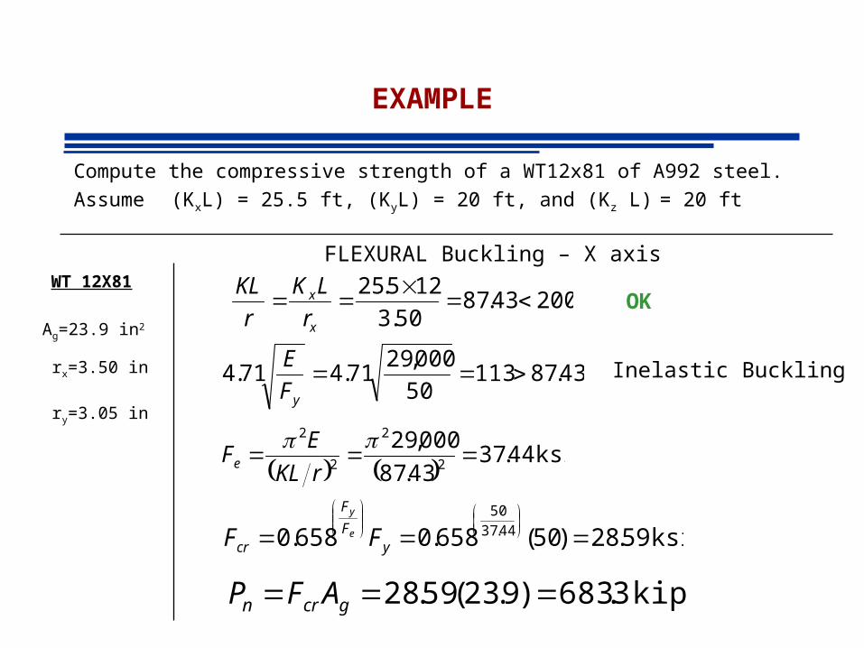
EXAMPLE
Compute the compressive strength of a WT12x81 of A992 steel.
Assume (KxL) = 25.5 ft, (KyL) = 20 ft, and (Kz L) = 20 ft
20043.8750.3
125.25
x
x
r
LK
r
KLOK
43.8711350
000,2971.471.4
yF
E
ksi 44.3743.87
000,292
2
2
2
rKL
EFe
ksi 59.28)50(658.0658.0 44.37
50
yF
F
cr FF e
y
Inelastic Buckling
FLEXURAL Buckling – X axisWT 12X81
Ag=23.9 in2
rx=3.50 in
ry=3.05 in
kips 3.683)9.23(59.28 gcrn AFP
EXAMPLE
20069.7805.3
1220
y
y
r
LKOK
ksi 22.46
69.78
000,292
2
2
2
yy
eyrLK
EF
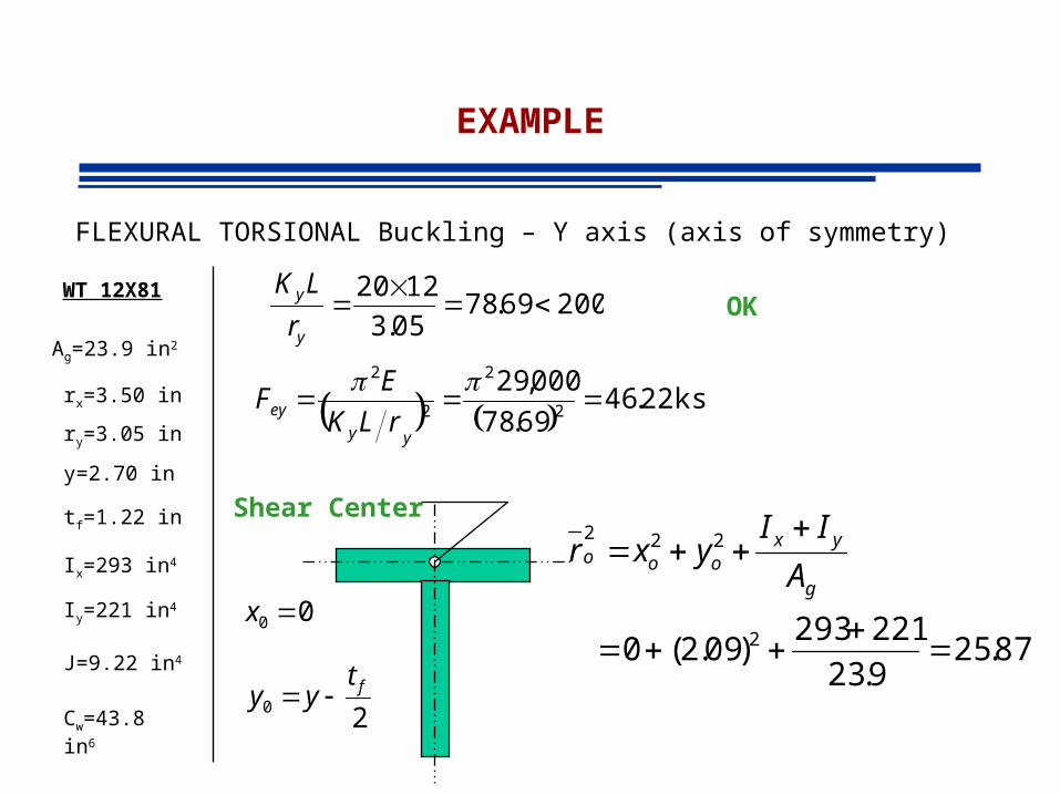
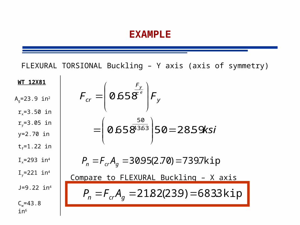
FLEXURAL TORSIONAL Buckling – Y axis (axis of symmetry)
WT 12X81
Ag=23.9 in2
rx=3.50 in
ry=3.05 in
y=2.70 in
tf=1.22 in
Ix=293 in4
Iy=221 in4
J=9.22 in4
Cw=43.8 in6
00 x
20ft
yy
87.259.23
221293)09.2(0 2
222
g
yxooo
A
IIyxr
Shear Center
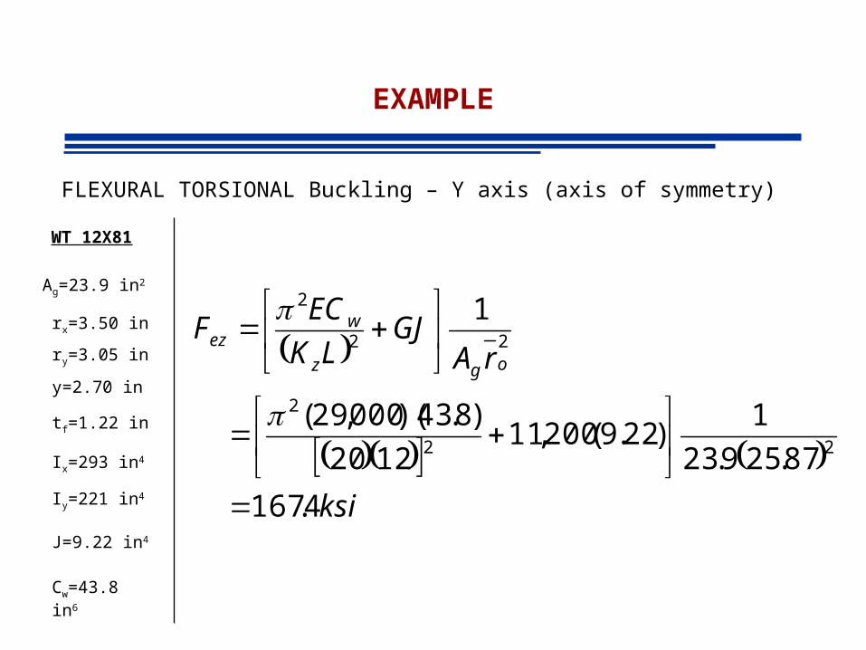
EXAMPLE
FLEXURAL TORSIONAL Buckling – Y axis (axis of symmetry)
WT 12X81
Ag=23.9 in2
rx=3.50 in
ry=3.05 in
y=2.70 in
tf=1.22 in
Ix=293 in4
Iy=221 in4
J=9.22 in4
Cw=43.8 in6
ksi
rAGJ
LK
ECF
ogz
wez
4.167
87.259.23
1)22.9(200,11
1220
)8.43)(000,29(
1
22
2
22
2
EXAMPLE
FLEXURAL TORSIONAL Buckling – Y axis (axis of symmetry)
WT 12X81
Ag=23.9 in2
rx=3.50 in
ry=3.05 in
y=2.70 in
tf=1.22 in
Ix=293 in4
Iy=221 in4
J=9.22 in4
Cw=43.8 in6
ksi
FF
HFF
H
FFF
ezey
ezeyezeye
63.53
4.16722.46
8312.04.16722.46411
8312.02
4.16722.46
411
2
2
8312.0
87.25
090.2011
2
2
22
o
oo
r
yxH
EXAMPLE
FLEXURAL TORSIONAL Buckling – Y axis (axis of symmetry)
WT 12X81
Ag=23.9 in2
rx=3.50 in
ry=3.05 in
y=2.70 in
tf=1.22 in
Ix=293 in4
Iy=221 in4
J=9.22 in4
Cw=43.8 in6
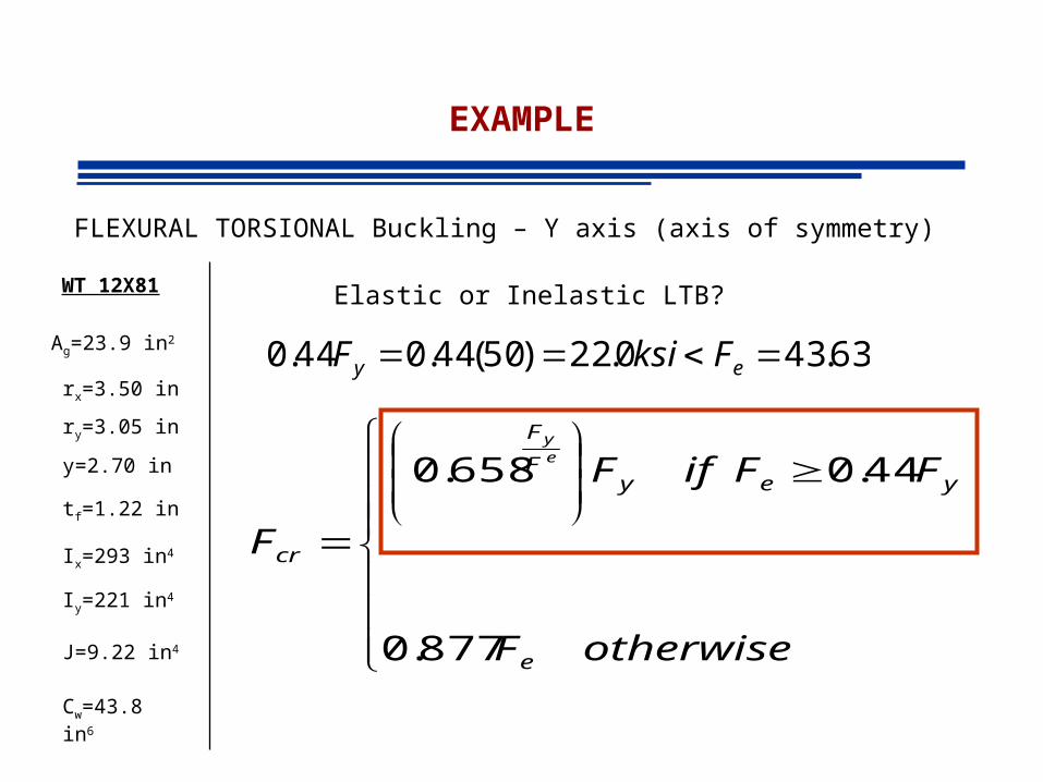
Elastic or Inelastic LTB?
63.430.22)50(44.044.0 ey FksiF
877.0
44.0 658.0
otherwiseF
FFifF
F
e
yeyF
F
cr
ey
EXAMPLE
FLEXURAL TORSIONAL Buckling – Y axis (axis of symmetry)
WT 12X81
Ag=23.9 in2
rx=3.50 in
ry=3.05 in
y=2.70 in
tf=1.22 in
Ix=293 in4
Iy=221 in4
J=9.22 in4
Cw=43.8 in6
ksi
FF yF
F
cr
ey
59.2850658.0
658.0
63.43
50
kips7.739)70.2(95.30 gcrn AFP
Compare to FLEXURAL Buckling – X axis
kips 3.683)9.23(82.21 gcrn AFP
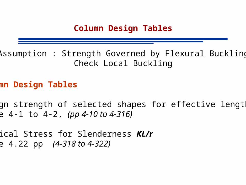
Column Design Tables
Assumption : Strength Governed by Flexural BucklingCheck Local Buckling
Column Design Tables
Design strength of selected shapes for effective length KLTable 4-1 to 4-2, (pp 4-10 to 4-316)
Critical Stress for Slenderness KL/rtable 4.22 pp (4-318 to 4-322)
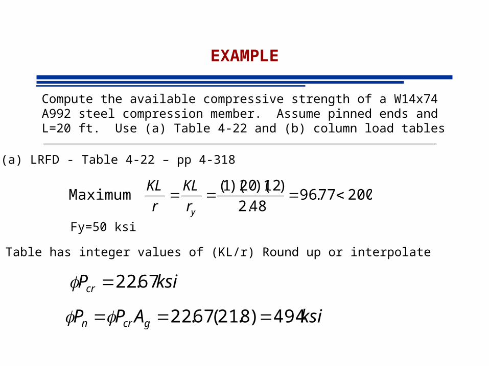
EXAMPLE
Compute the available compressive strength of a W14x74 A992 steel compression member. Assume pinned ends and L=20 ft. Use (a) Table 4-22 and (b) column load tables
(a) LRFD - Table 4-22 – pp 4-318
20077.9648.2
)12)(20)(1(Maximum
yr
KL
r
KL
Table has integer values of (KL/r) Round up or interpolate
Fy=50 ksi
ksiPcr 67.22
ksiAPP gcrn 494)8.21(67.22

EXAMPLE
Compute the available compressive strength of a W14x74 A992 steel compression member. Assume pinned ends and L=20 ft. Use (a) Table 4-22 and (b) column load tables
(b) LRFD Column Load Tables
ftKL 20)20)(1(Maximum Tabular values based on minimum radius of gyration
Fy=50 ksi
kipsPnc 494
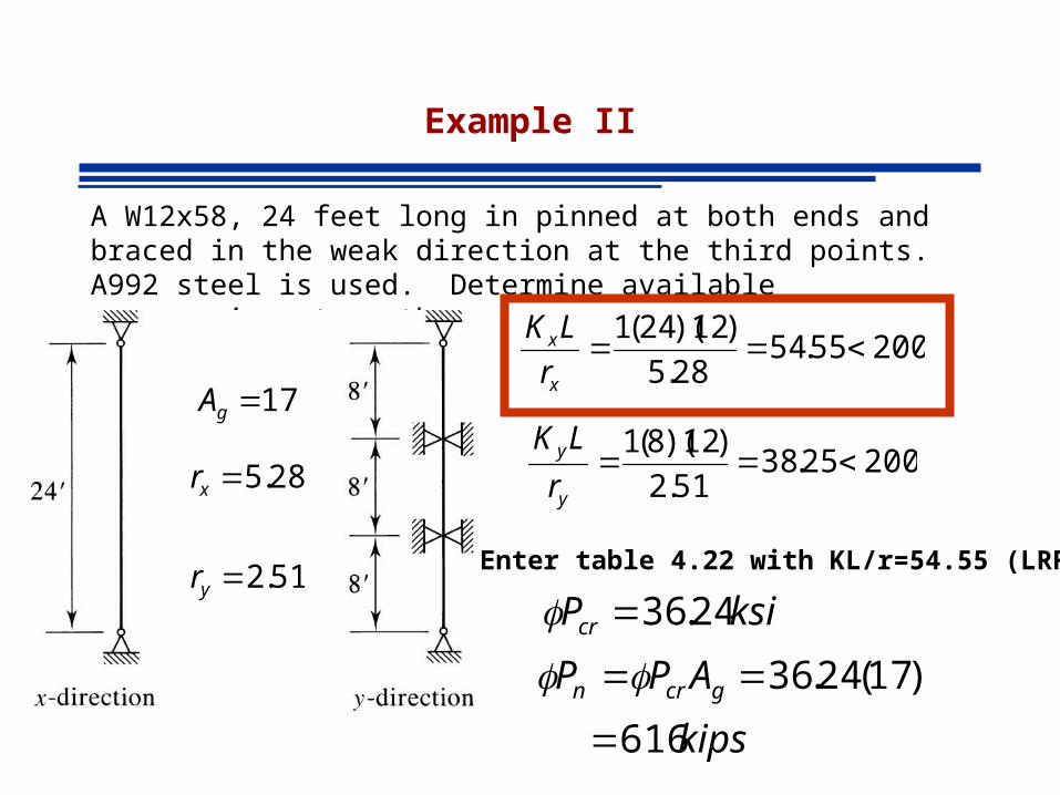
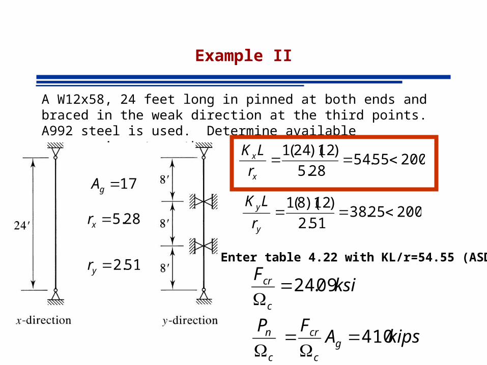
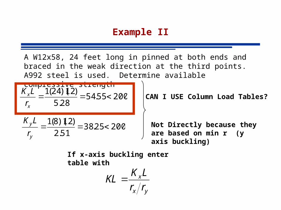
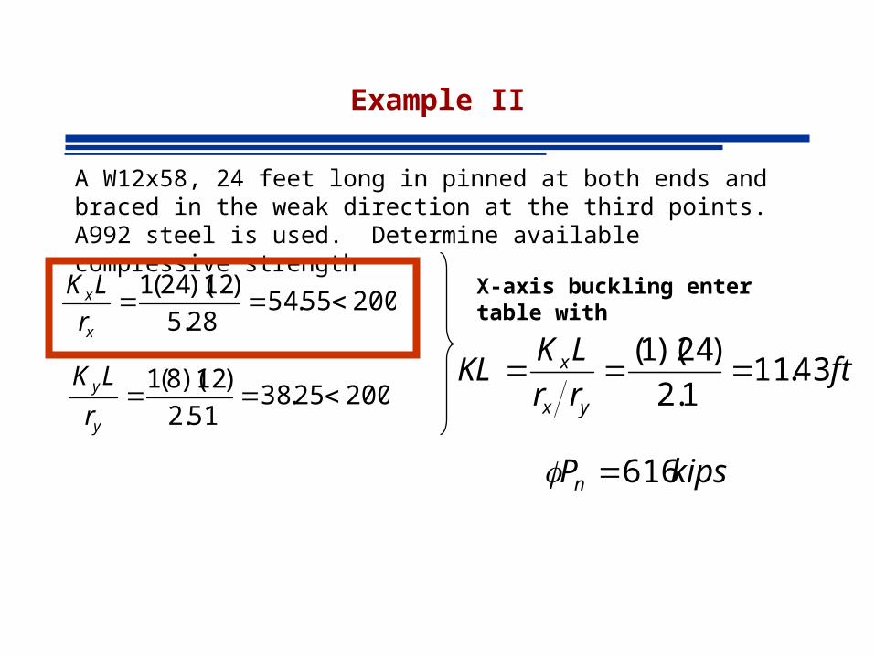
Example II
A W12x58, 24 feet long in pinned at both ends and braced in the weak direction at the third points. A992 steel is used. Determine available compressive strength
20025.3851.2
)12)(8(1
y
y
r
LK
20055.5428.5
)12)(24(1
x
x
r
LK
Enter table 4.22 with KL/r=54.55 (LRFD)
28.5xr
51.2yrksiPcr 24.36
kips
APP gcrn
616
)17(24.36
17gA
Example II
A W12x58, 24 feet long in pinned at both ends and braced in the weak direction at the third points. A992 steel is used. Determine available compressive strength
20025.3851.2
)12)(8(1
y
y
r
LK
20055.5428.5
)12)(24(1
x
x
r
LK
Enter table 4.22 with KL/r=54.55 (ASD)
28.5xr
51.2yr
ksiF
c
cr 09.24
kipsAFP
gc
cr
c
n 410
17gA
Example II
A W12x58, 24 feet long in pinned at both ends and braced in the weak direction at the third points. A992 steel is used. Determine available compressive strength
20025.3851.2
)12)(8(1
y
y
r
LK
20055.5428.5
)12)(24(1
x
x
r
LKCAN I USE Column Load Tables?
yx
x
rr
LKKL
Not Directly because they are based on min r (y axis buckling)
If x-axis buckling enter table with
Example II
A W12x58, 24 feet long in pinned at both ends and braced in the weak direction at the third points. A992 steel is used. Determine available compressive strength
20025.3851.2
)12)(8(1
y
y
r
LK
20055.5428.5
)12)(24(1
x
x
r
LK X-axis buckling enter table with
ftrr
LKKL
yx
x 43.111.2
)24)(1(
kipsPn 616