Embed Size (px)
Citation preview
C. R. Mecanique 344 (2016) 623–630
Contents lists available at ScienceDirect
Comptes Rendus Mecanique
www.sciencedirect.com
Evolutionary fracture analysis of masonry arches: Effects of
shallowness ratio and size scale
Federico Accornero, Giuseppe Lacidogna, Alberto Carpinteri
Politecnico di Torino, Department of Structural, Geotechnical and Building Engineering, Corso Duca degli Abruzzi 24, 10129 Torino, Italy
a r t i c l e i n f o a b s t r a c t
Article history:Received 21 March 2016Accepted 19 May 2016Available online 10 June 2016
Keywords:Masonry structuresMasonry archesEvolutionary analysisFracturing benefitScale effectBrittleness numberShallowness ratio
Masonry arch structures can be determined by means of a detailed analysis that takes into account the intermediate cracking stage, which takes place when the tensile strength of the material has been exceeded, even though the collapse mechanism has not formed yet. Such a hypothesis is based on a constitutive law that returns a closer approximation to the actual material’s behaviour.This paper presents the evolutionary analysis for the fracturing assessment of masonry arches. This method allows capturing the damaging process that occurs when the linear elastic behaviour’s conditions in tension no longer apply, and before achieving the limit conditions. Furthermore, the way the thrust line is influenced by the formation of cracks and the consequent internal stresses redistribution, representing the “fracturing benefit”, can be assessed numerically. Size scale effects are also taken into account, as well as the influence of the arch’s shallowness ratio.
© 2016 Published by Elsevier Masson SAS on behalf of Académie des sciences.
1. Fracturing process in masonry arches
Masonry is characterised by both anisotropic and nonlinear behaviour; such behaviours are detected even at low strain values [1–3]. When undergoing uniaxial loading tests, masonry shows appreciably different values relating to tensile and compressive strength: the latter results to be significantly higher than the former.
The elastic-softening constitutive law is that which best represents the natural or artificial masonry behaviour. This corresponds to simply considering an elastic constitutive law associated with a fracturing crisis condition consistent with the concepts of Linear Elastic Fracture Mechanics (LEFM). This means that the material has merely elastic behaviour with the possibility that cracks might form and propagate [4,5].
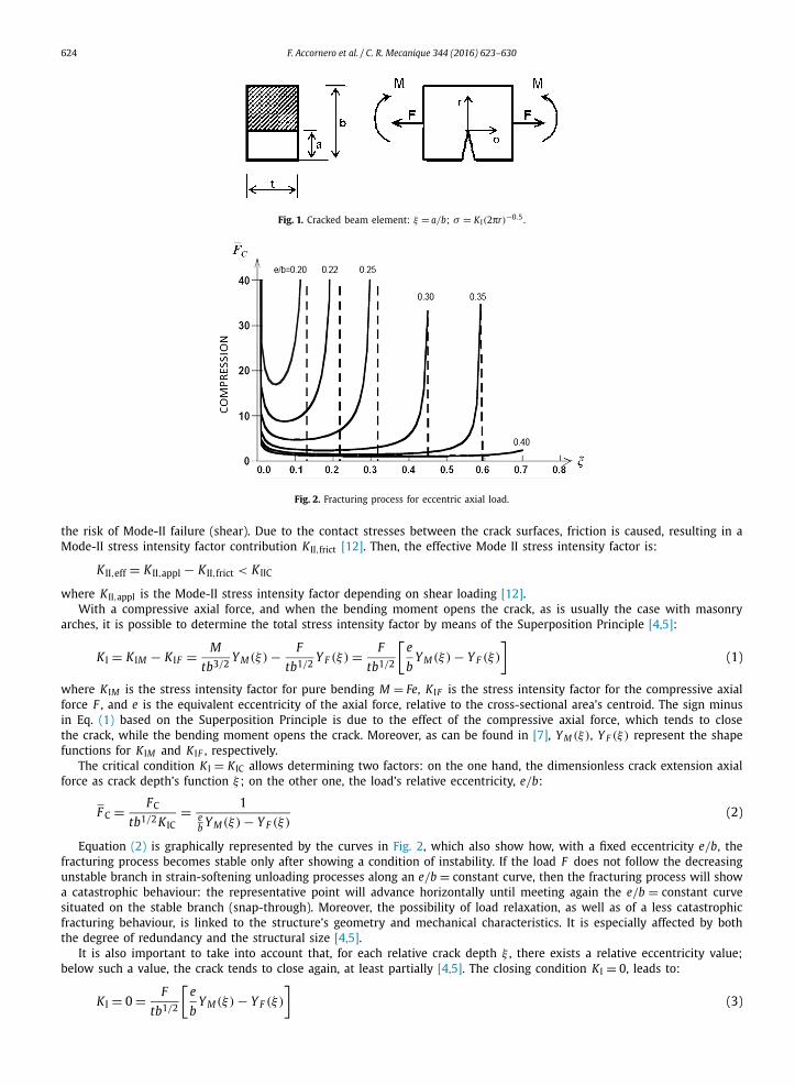
The crack depth ξ = a/b (Fig. 1a), as well as the stress intensity factor, K I (Fig. 1b) will be taken into consideration as damage parameter and load parameter respectively. The Mode-I stress intensity factor can be considered a stress field’s amplification factor when the loads are symmetrical to the crack (e.g., axial force and bending moment) [4–7].
Shear is disregarded [8–11]. The validity of this assumption, taking into account the Mery’s theory [8], and the Heyman’s hypotheses of Limit Analysis [10], can be verified considering the slope of the arch thrust line with respect to the joint lines. If the thrust line affects the joints with a slope less than the angle of friction, no mutual sliding takes place between two adjacent elements [11]. Also by a LEFM point of view, the presence of the compressive stresses in the arch structure reduces
E-mail address: [email protected] (F. Accornero).
http://dx.doi.org/10.1016/j.crme.2016.05.0021631-0721/© 2016 Published by Elsevier Masson SAS on behalf of Académie des sciences.
624 F. Accornero et al. / C. R. Mecanique 344 (2016) 623–630
Fig. 1. Cracked beam element: ξ = a/b; σ = K I(2πr)−0.5.
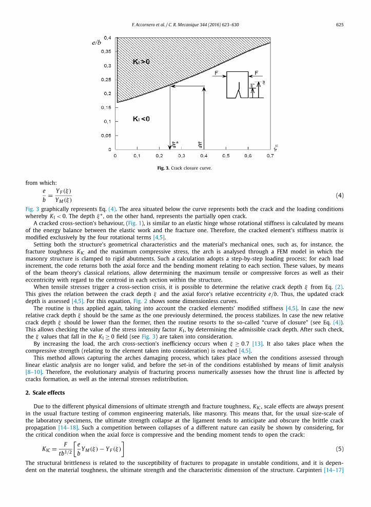
Fig. 2. Fracturing process for eccentric axial load.
the risk of Mode-II failure (shear). Due to the contact stresses between the crack surfaces, friction is caused, resulting in a Mode-II stress intensity factor contribution K II,frict [12]. Then, the effective Mode II stress intensity factor is:
K II,eff = K II,appl − K II,frict < K IIC
where K II,appl is the Mode-II stress intensity factor depending on shear loading [12].With a compressive axial force, and when the bending moment opens the crack, as is usually the case with masonry
arches, it is possible to determine the total stress intensity factor by means of the Superposition Principle [4,5]:
K I = K IM − K IF = M
tb3/2Y M(ξ) − F
tb1/2Y F (ξ) = F
tb1/2
[e
bY M(ξ) − Y F (ξ)
](1)
where K IM is the stress intensity factor for pure bending M = Fe, K IF is the stress intensity factor for the compressive axial force F , and e is the equivalent eccentricity of the axial force, relative to the cross-sectional area’s centroid. The sign minus in Eq. (1) based on the Superposition Principle is due to the effect of the compressive axial force, which tends to close the crack, while the bending moment opens the crack. Moreover, as can be found in [7], Y M (ξ), Y F (ξ) represent the shape functions for K IM and K IF , respectively.
The critical condition K I = K IC allows determining two factors: on the one hand, the dimensionless crack extension axial force as crack depth’s function ξ ; on the other one, the load’s relative eccentricity, e/b:
F C = FC
tb1/2 K IC= 1
eb Y M(ξ) − Y F (ξ)
(2)
Equation (2) is graphically represented by the curves in Fig. 2, which also show how, with a fixed eccentricity e/b, the fracturing process becomes stable only after showing a condition of instability. If the load F does not follow the decreasing unstable branch in strain-softening unloading processes along an e/b = constant curve, then the fracturing process will show a catastrophic behaviour: the representative point will advance horizontally until meeting again the e/b = constant curve situated on the stable branch (snap-through). Moreover, the possibility of load relaxation, as well as of a less catastrophic fracturing behaviour, is linked to the structure’s geometry and mechanical characteristics. It is especially affected by both the degree of redundancy and the structural size [4,5].
It is also important to take into account that, for each relative crack depth ξ , there exists a relative eccentricity value; below such a value, the crack tends to close again, at least partially [4,5]. The closing condition K I = 0, leads to:
K I = 0 = F1/2
[e
Y M(ξ) − Y F (ξ)
](3)
tb b
F. Accornero et al. / C. R. Mecanique 344 (2016) 623–630 625
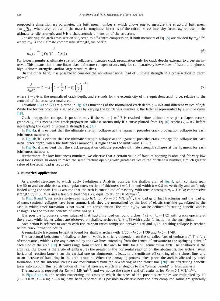
Fig. 3. Crack closure curve.
from which:e
b= Y F (ξ)
Y M(ξ)(4)
Fig. 3 graphically represents Eq. (4). The area situated below the curve represents both the crack and the loading conditions whereby K I < 0. The depth ξ∗ , on the other hand, represents the partially open crack.
A cracked cross-section’s behaviour, (Fig. 1), is similar to an elastic hinge whose rotational stiffness is calculated by means of the energy balance between the elastic work and the fracture one. Therefore, the cracked element’s stiffness matrix is modified exclusively by the four rotational terms [4,5].
Setting both the structure’s geometrical characteristics and the material’s mechanical ones, such as, for instance, the fracture toughness K IC and the maximum compressive stress, the arch is analysed through a FEM model in which the masonry structure is clamped to rigid abutments. Such a calculation adopts a step-by-step loading process; for each load increment, the code returns both the axial force and the bending moment relating to each section. These values, by means of the beam theory’s classical relations, allow determining the maximum tensile or compressive forces as well as their eccentricity with regard to the centroid in each section within the structure.
When tensile stresses trigger a cross-section crisis, it is possible to determine the relative crack depth ξ from Eq. (2). This gives the relation between the crack depth ξ and the axial force’s relative eccentricity e/b. Thus, the updated crack depth is assessed [4,5]. For this equation, Fig. 2 shows some dimensionless curves.
The routine is thus applied again, taking into account the cracked elements’ modified stiffness [4,5]. In case the new relative crack depth ξ should be the same as the one previously determined, the process stabilizes. In case the new relative crack depth ξ should be lower than the former, then the routine resorts to the so-called “curve of closure” (see Eq. (4)). This allows checking the value of the stress intensity factor K I , by determining the admissible crack depth. After such check, the ξ values that fall in the K I ≥ 0 field (see Fig. 3) are taken into consideration.
By increasing the load, the arch cross-section’s inefficiency occurs when ξ ≥ 0.7 [13]. It also takes place when the compressive strength (relating to the element taken into consideration) is reached [4,5].
This method allows capturing the arches damaging process, which takes place when the conditions assessed through linear elastic analysis are no longer valid, and before the set-in of the conditions established by means of limit analysis [8–10]. Therefore, the evolutionary analysis of fracturing process numerically assesses how the thrust line is affected by cracks formation, as well as the internal stresses redistribution.
2. Scale effects
Due to the different physical dimensions of ultimate strength and fracture toughness, K IC , scale effects are always present in the usual fracture testing of common engineering materials, like masonry. This means that, for the usual size-scale of the laboratory specimens, the ultimate strength collapse at the ligament tends to anticipate and obscure the brittle crack propagation [14–18]. Such a competition between collapses of a different nature can easily be shown by considering, for the critical condition when the axial force is compressive and the bending moment tends to open the crack:
K IC = F
tb1/2
[e
bY M(ξ) − Y F (ξ)
](5)
The structural brittleness is related to the susceptibility of fractures to propagate in unstable conditions, and it is depen-dent on the material toughness, the ultimate strength and the characteristic dimension of the structure. Carpinteri [14–17]
626 F. Accornero et al. / C. R. Mecanique 344 (2016) 623–630
proposed a dimensionless parameter, the brittleness number s, which allows one to measure the structural brittleness, s = K IC
σub1/2 , where K IC represents the material toughness in terms of the critical stress-intensity factor, σu represents the ultimate tensile strength, and b is a characteristic dimension of the structure.
Considering the arch cross section subjected to off-centre compression, if both members of Eq. (5) are divided by σucb1/2, where σuc is the ultimate compressive strength, we obtain:
F
σuctb= s
eb Y M(ξ) − Y F (ξ)
(6)
For lower s numbers, ultimate strength collapse anticipates crack propagation only for crack depths external to a certain in-terval. This means that a true linear elastic fracture collapse occurs only for comparatively low values of fracture toughness, high ultimate strengths, and/or large structure sizes.
On the other hand, it is possible to consider the non-dimensional load of ultimate strength in a cross-section of depth (b)–(a):
F
σuctb= (1 − ξ)
[1 + 1
6(1 − ξ)
(e
b
)−1](7)
where ξ = a/b is the normalized crack depth, and e stands for the eccentricity of the equivalent axial force, relative to the centroid of the cross-sectional area.
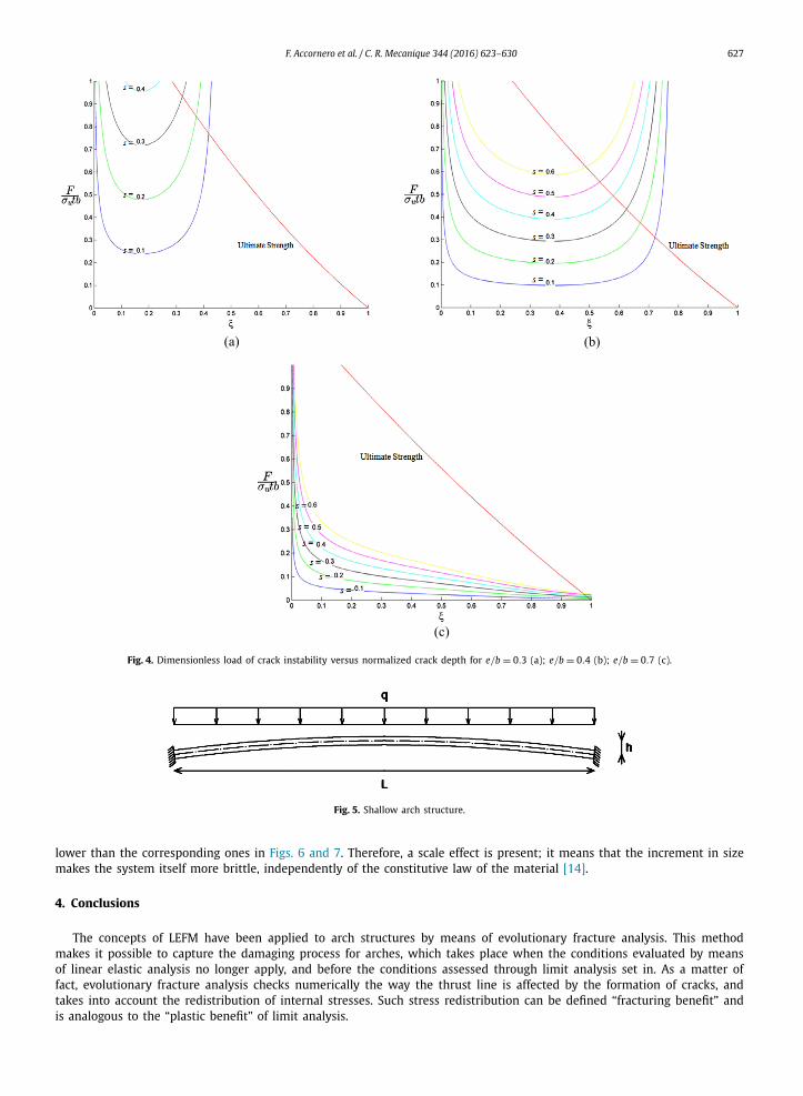
Equations (6) and (7) are plotted in Fig. 4 as functions of the normalized crack depth ξ = a/b and different values of e/b. While the former produces a set of curves by varying the brittleness number s, the latter is represented by a unique curve [18].
Crack propagation collapse is possible only if the value ξ = 0.7 is reached before ultimate strength collapse occurs; graphically, this means that crack propagation collapse occurs only if a curve plotted from Eq. (6) reaches ξ = 0.7 before intercepting the curve of ultimate strength (Eq. (7)).
In Fig. 4a, it is evident that the ultimate strength collapse at the ligament precedes crack propagation collapse for each brittleness number s.
In Fig. 4b, it is evident that the ultimate strength collapse at the ligament precedes crack propagation collapse for each initial crack depth, when the brittleness number s is higher than the limit value s = 0.2.
In Fig. 4c, it is evident that the crack propagation collapse precedes ultimate strength collapse at the ligament for each brittleness number s.
Furthermore, for low brittleness numbers, we observe that a certain value of fracture opening is obtained for very low axial loads values. In order to reach the same fracture opening with greater values of the brittleness number, a much greater value of the axial load is required.
3. Numerical applications
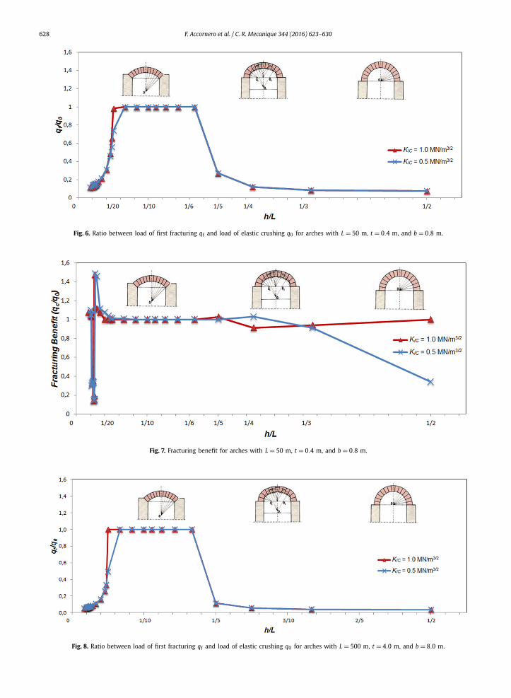
As a model structure, to which apply Evolutionary Analysis, consider the shallow arch of Fig. 5, with constant span L = 50 m and variable rise h, rectangular cross section of thickness t = 0.4 m and width b = 0.8 m, vertically and uniformly loaded along the span. Let us assume that the arch is constituted of masonry, with tensile strength σt = 3 MPa; compressive strength σu = 50 MPa and a fracture toughness K IC equal to 0.5 or 1.0 MN/m3/2.
In Figs. 6 and 7, for each rise-to-span ratio h/L, for K IC = 0.5 MN/m3/2, the load qf of first fracturing and the load qcof cross-sectional collapse have been summarized; they are normalized by the load of elastic crushing q0 , related to the case in which crack formation is not taken into consideration. The ratio qc/q0 can be defined “fracturing benefit” and is analogous to the “plastic benefit” of Limit Analysis.
It is possible to observe lower values of first fracturing load on round arches (1/3 < h/L < 1/2) with cracks opening at the crown, while higher values are observed on shallow arches (h/L < 1/6) with cracks formation at the springings.
Arch action is referred to arches with rise-to-span ratios comprised between 1/6 and 1/15: crushing collapse is reached before crack formation occurs.
A remarkable fracturing benefit is found for shallow arches with 1/20 > h/L > 1/39 and h/L < 1/48.The structural behaviour of shallow arches or vaults is strictly dependent on the so-called “arc of embrasure”. The “arc
of embrasure”, which is the angle created by the two lines extending from the centre of curvature to the springing point of each side of the arch [19]. It could range from 0◦ for a flat arch to 180◦ for a full semicircular arch. The shallower is the arch (i.e. the lower is the angle of embrasure) the greater is the horizontal reaction on the abutments. For arches having horizontal reaction larger than the vertical one on abutments, it leads to a significant off-centring of the thrust line, and to an increase of fracturing in the arch structure. When the damaging process takes place, the arch is affected by crack formation, and the internal stresses are redistributed with the re-entering of the thrust line [20]. The “fracturing benefit” takes into account this redistribution of internal stresses, which is analogous to the “plastic benefit” of limit analysis.
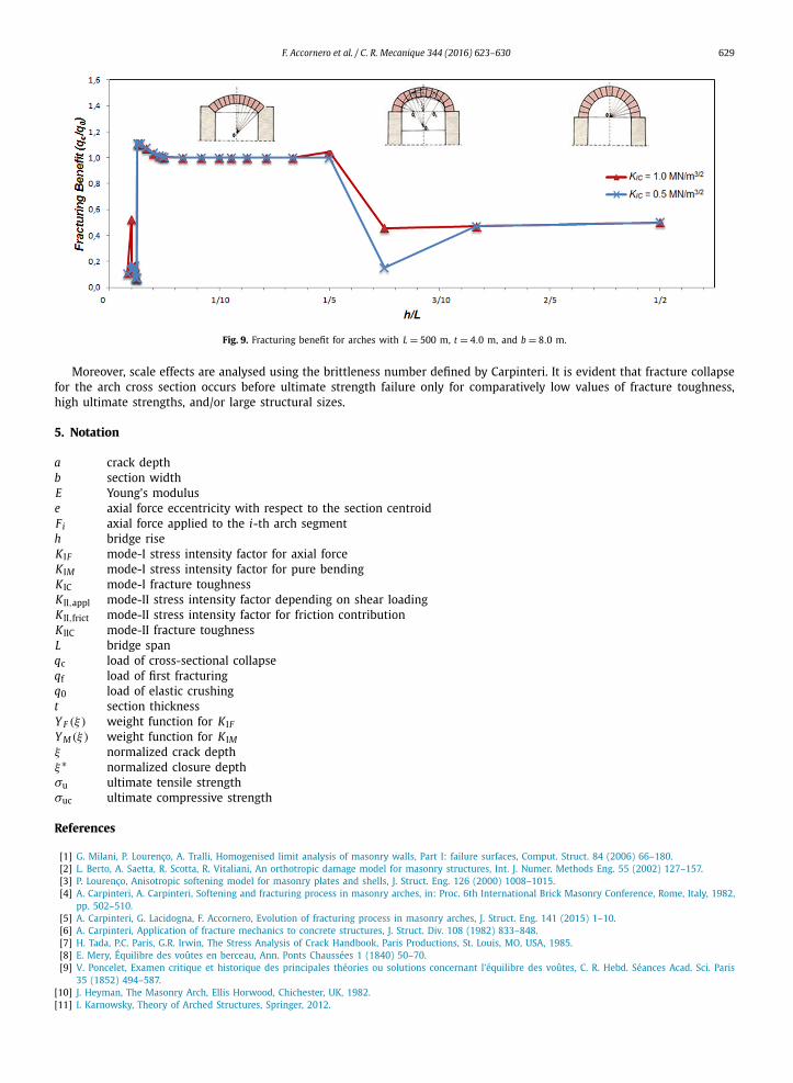
The analysis is repeated for K IC = 1 MN/m3/2, and we notice the same trend of results as for K IC = 0.5 MN/m3/2.In Figs. 8 and 9, the results concerning the cases in which the sizes of the previous examples are multiplied by 10
(L = 500 m; t = 4 m; b = 8 m) have been reported. It is possible to observe how the new computed ratios are generally
F. Accornero et al. / C. R. Mecanique 344 (2016) 623–630 627
Fig. 4. Dimensionless load of crack instability versus normalized crack depth for e/b = 0.3 (a); e/b = 0.4 (b); e/b = 0.7 (c).
Fig. 5. Shallow arch structure.
lower than the corresponding ones in Figs. 6 and 7. Therefore, a scale effect is present; it means that the increment in size makes the system itself more brittle, independently of the constitutive law of the material [14].
4. Conclusions
The concepts of LEFM have been applied to arch structures by means of evolutionary fracture analysis. This method makes it possible to capture the damaging process for arches, which takes place when the conditions evaluated by means of linear elastic analysis no longer apply, and before the conditions assessed through limit analysis set in. As a matter of fact, evolutionary fracture analysis checks numerically the way the thrust line is affected by the formation of cracks, and takes into account the redistribution of internal stresses. Such stress redistribution can be defined “fracturing benefit” and is analogous to the “plastic benefit” of limit analysis.
628 F. Accornero et al. / C. R. Mecanique 344 (2016) 623–630
Fig. 6. Ratio between load of first fracturing qf and load of elastic crushing q0 for arches with L = 50 m, t = 0.4 m, and b = 0.8 m.
Fig. 7. Fracturing benefit for arches with L = 50 m, t = 0.4 m, and b = 0.8 m.
Fig. 8. Ratio between load of first fracturing qf and load of elastic crushing q0 for arches with L = 500 m, t = 4.0 m, and b = 8.0 m.
F. Accornero et al. / C. R. Mecanique 344 (2016) 623–630 629
Fig. 9. Fracturing benefit for arches with L = 500 m, t = 4.0 m, and b = 8.0 m.
Moreover, scale effects are analysed using the brittleness number defined by Carpinteri. It is evident that fracture collapse for the arch cross section occurs before ultimate strength failure only for comparatively low values of fracture toughness, high ultimate strengths, and/or large structural sizes.
5. Notation
a crack depthb section widthE Young’s moduluse axial force eccentricity with respect to the section centroidFi axial force applied to the i-th arch segmenth bridge riseK IF mode-I stress intensity factor for axial forceK IM mode-I stress intensity factor for pure bendingK IC mode-I fracture toughnessK II,appl mode-II stress intensity factor depending on shear loadingK II,frict mode-II stress intensity factor for friction contributionK IIC mode-II fracture toughnessL bridge spanqc load of cross-sectional collapseqf load of first fracturingq0 load of elastic crushingt section thicknessY F (ξ) weight function for K IFY M(ξ) weight function for K IMξ normalized crack depthξ∗ normalized closure depthσu ultimate tensile strengthσuc ultimate compressive strength
References
[1] G. Milani, P. Lourenço, A. Tralli, Homogenised limit analysis of masonry walls, Part I: failure surfaces, Comput. Struct. 84 (2006) 66–180.[2] L. Berto, A. Saetta, R. Scotta, R. Vitaliani, An orthotropic damage model for masonry structures, Int. J. Numer. Methods Eng. 55 (2002) 127–157.[3] P. Lourenço, Anisotropic softening model for masonry plates and shells, J. Struct. Eng. 126 (2000) 1008–1015.[4] A. Carpinteri, A. Carpinteri, Softening and fracturing process in masonry arches, in: Proc. 6th International Brick Masonry Conference, Rome, Italy, 1982,
pp. 502–510.[5] A. Carpinteri, G. Lacidogna, F. Accornero, Evolution of fracturing process in masonry arches, J. Struct. Eng. 141 (2015) 1–10.[6] A. Carpinteri, Application of fracture mechanics to concrete structures, J. Struct. Div. 108 (1982) 833–848.[7] H. Tada, P.C. Paris, G.R. Irwin, The Stress Analysis of Crack Handbook, Paris Productions, St. Louis, MO, USA, 1985.[8] E. Mery, Équilibre des voûtes en berceau, Ann. Ponts Chaussées 1 (1840) 50–70.[9] V. Poncelet, Examen critique et historique des principales théories ou solutions concernant l’équilibre des voûtes, C. R. Hebd. Séances Acad. Sci. Paris
35 (1852) 494–587.[10] J. Heyman, The Masonry Arch, Ellis Horwood, Chichester, UK, 1982.[11] I. Karnowsky, Theory of Arched Structures, Springer, 2012.

630 F. Accornero et al. / C. R. Mecanique 344 (2016) 623–630
[12] T. Fett, Mixed mode stress intensity factor for partially opened cracks, Int. J. Fract. 111 (2001) 67–72.[13] UIC Code 778-3, Recommendations for the assessment of the load carrying capacity of existing masonry and mass-concrete arch bridges, Paris, Inter-
national Union of Railways (UIC), 1995.[14] A. Carpinteri, Size effect in fracture toughness testing: a dimensional analysis approach, in: Proc. International Conference in Analytical and Experi-
mental Fracture Mechanics, Rome, Italy, 1980, pp. 785–797.[15] A. Carpinteri, Static and energetic fracture parameters for rocks and concretes, Mater. Struct. 14 (1981) 151–162.[16] A. Carpinteri, Experimental determination of fracture toughness parameters K IC and J IC for aggregative materials, in: Proc. 5th International Conference
on Fracture, Cannes, France, 1981, pp. 1491–1498.[17] A. Carpinteri, Notch sensitivity in fracture testing of aggregative materials, Eng. Fract. Mech. 16 (1982) 467–481.[18] A. Carpinteri, P. Cornetti, S. Puzzi, Scaling laws and multi-scale approach in the mechanics of heterogeneous and disordered materials, Appl. Mech. Rev.
59 (2006) 283–305.[19] L.C. Lancaster, Concrete Vaulted Construction in Imperial Rome: Innovations in Context, Cambridge University Press, 2005.[20] M. Betti, G.A. Drosopoulos, G.E. Stavroulakis, Two non-linear finite element models developed for the assessment of failure of masonry arches, C. R.,
Mecanique 336 (2008) 42–53.