Embed Size (px)
Citation preview
©2012 Axzo Press Page 1 of 28 July 9, 2012
C o m p T I A A + C e r t i f i c a t i o n : Essentials (2009 Edit ion) Frequently asked questions and instructor notes
Topic A: Classroom setup All our courses assume that each student has a personal computer to use during the class. Our hands-on approach to learning requires that they do. This topic gives information on how to set up the classroom to teach this course. It includes minimum requirements for the students’ personal computers, setup information for the first time you teach the class, and setup information for each time that you teach after the first time you set up the classroom.
Hardware requirements The instructor’s and each student’s personal desktop computer should have:
• A keyboard and a pointing device such as a mouse • 800 MHz processor (1 GHz recommended) • 512 MB RAM (1 GB recommended • 20 GB hard disk with 15 GB space available (40 GB with 15 GB available
recommended) • DVD-R ROM drive • SuperVGA monitor, with DirectX 9 support; Windows Display Driver Model
(WDDM); 128 MB graphics memory; Pixel Shader 2.0 (hardware); 32 bits per pixel recommended
• Wired NIC • Modem • Sound card • A video card with two monitor ports for the independent practice activity in the
“Video output ad image input devices” unit. If the video adapter cards in your computers have only one monitor port, students can do all other activities in the course, but will not be able to complete this independent practice activity.
Activity hardware requirements In addition to the hardware requirements for the instructor’s and each student’s personal desktop computer, you will need the following hardware for each student to complete
CompTIA A+ Certification: Essentials (2009 Edition) FAQ & Instructor Notes
©2012 Axzo Press Page 2 of 28 July 9, 2012
various course activities. If you don’t have enough hardware for each student, you can have students work in small groups, or you can perform the activity as a demonstration.
• Unit 5 (The Basic Input/Output System): − Bootable floppy or bootable CD/DVD
• Unit 7 (Bus structures): − Various types of adapter cards or photos of adapter cards − Various motherboards or photos of motherboards
• Unit 9 (Peripheral connection types): − Serial cable and device − Parallel cable and device − KVM switch − USB cable and device − IEEE 1394 (FireWire) cable and device − Speakers − Microphone − Multimedia device (coax, MIDI, S/PDIF) − Various types of connectors or photos of connectors
• Unit 10 (Data storage devices): − Audio CD − USB flash drive − Floppy disk − Floppy disk drive (optional) − DVD-R disc
• Unit 11 (Video output and image input devices): − CRT monitor − LCD monitor − Scanner − Digital camera − Web camera
• Unit 12 (Printers): − Local Vista-compatible printer
• Unit 13 (Connecting computers): − Twisted-pair cable with a clear RJ-45 connector on the end − RG-6 or RG-59 cable and RG-58 coax cable with attached connector
• Unit 14 (Networking computers): − Wireless access point (for instructor demonstration activity) − Wireless client (for instructor demonstration activity)
• Unit 15 (Portable computers): − Notebook computer with PC card
CompTIA A+ Certification: Essentials (2009 Edition) FAQ & Instructor Notes
©2012 Axzo Press Page 3 of 28 July 9, 2012
− Port replicator or docking station − Cleaning products for notebook − Packaging materials for the notebook − Hot-swappable device
• Unit 18 (Security): − USB flash drive for optional instructor demonstration activity
• Unit 20 (Safety and maintenance): − UPS − Cleaning supplies for desktop computer and peripherals
• Unit 21 (Troubleshooting hardware): − A backup location: CD/DVD-R, network share, or space on the second
partition
Software requirements You will need the following software:
• Windows Vista Business installation files and product keys for both classroom setup and an activity in Unit 19, “Windows installation and upgrades.”
• Windows Vista Ultimate installation files and product keys for an activity in Unit 19.
• Windows XP Professional installation files and product keys for the independent practice activity in Unit 19.
• Any Windows XP drivers needed for the independent practice activity in Unit 19.
• Any Windows XP application software for an activity in Unit 19. • Windows Upgrade Advisor, which can be downloaded from Microsoft’s
Downloads Web site.
Note: Because students will need to conduct multiple operating system installations in the “Windows installation and upgrades” unit, operating system discs should be slipstreamed with the latest service packs, if at all possible.
Network requirements The following network components and connectivity are also required for this course:
• Internet access, for the following purposes: – Downloading the latest critical updates and service packs from
www.windowsupdate.com – Completing activities within the units. – Downloading the Student Data files from www.axzopress.com (if necessary) • Classroom computers need to be connected through TCP/IP and receive IP
addressing information from a DHCP server. • You will need a range of IP addresses so that students can switch to manual
configuration in an activity in Unit 14, “Networking computers.”
CompTIA A+ Certification: Essentials (2009 Edition) FAQ & Instructor Notes
©2012 Axzo Press Page 4 of 28 July 9, 2012
First-time setup instructions The first time you teach this course, you will need to perform the following steps to set up each student computer.
1 Install Windows Vista Business on an NTFS partition according to the software manufacturer’s instructions. Leave at least 1 GB of unallocated space on the drive. • Create an administrative user account: ESSADMIN## (where ## is a
unique number for each student and the instructor), with a password of Pa$$321.
• Create a standard user account: ESSUSER## (where ## is the same unique number that was assigned to each student’s ESSADMIN## account), with a password of Pa$$321.
• Turn on Network Discovery in a private network. • Turn on File Sharing.
2 Use Device Manager to verify that all devices are functional. If you need to download Windows Vista–compatible drivers for any devices from the manufacturers’ Web sites, keep a copy of the drivers for use during class.
3 Verify that you have Internet access. 4 If you don’t have the data CD that came with this manual, download the Student
Data files for the course. You can download the data directly to student machines, to a central location on your own network, or to a disk.
a Connect to www.axzopress.com. b Under Downloads, click Instructor-Led Training. c Browse the subject categories to locate your course. Then click the course
title to display a list of available downloads. (You can also access these downloads through our Catalog listings.)
d Click the link(s) for downloading the Student Data files, and follow the instructions that appear on your screen.
Keep a copy of the files where students can access them after reinstallation in Unit 19, “Windows installation and upgrades.”
Setting up the troubleshooting lab Unit 15, “Portable computers,” includes a troubleshooting lab. In this lab, students are asked to solve problems related to the material of that unit. This section presents ideas for problems that can be implemented.
We suggest two ways to implement these problems. In the first, you would send students off to a break while you induce these problems in their computers. In the second scenario, you would divide students into two groups. Each group would induce problems in a set of computers. The groups would switch places and solve the problems that the other group created.
When determining which problems to implement, make sure you consider the technical proficiency of your students.
Unit 15, Portable computers
CompTIA A+ Certification: Essentials (2009 Edition) FAQ & Instructor Notes
©2012 Axzo Press Page 5 of 28 July 9, 2012
For the Topic B activity titled “Troubleshooting notebook problems,” you could implement one or problems by doing any of the following:
• Install an uncharged battery. • Install a battery that won’t keep a charge. • Disconnect or loosely connect the power cord. • Plug the power cord into a power strip, but turn off the power strip. • Connect the notebook to an external keyboard and boot it. Then disconnect the
external keyboard without pressing the Fn key combination to switch back to the notebook keyboard (this often results in the keyboard having the numeric keypad enabled on the letter keys).
• Connect the notebook to an external monitor, switch to the external monitor, and then disconnect the monitor.
• Remove the hard drive. • Remove any PC cards. • Install a non-working PC card. • Remove a memory module. • Install additional memory, but don’t configure the system to recognize it. • Don’t fully seat a memory module. • Remove the drivers for any PC cards that are installed. • Set the power options so that the monitor and hard drive are turned off after 1
minute of inactivity. • Plug in an external monitor and/or keyboard, leave the notebook open, and place
the external components behind the notebook and facing the other direction so that it’s not obvious that they are connected to the notebook.
• Loosely connect peripheral cables. • Disconnect the network cable. • Remove the battery, power cable, and hard drive. Provide the wrong power
cable, battery, and hard drive to each student. • If the power cord comes apart in the middle where the transformer is, disconnect
or loosely connect this connection. • Plug the notebook into a power strip that is turned off, and remove the battery or
install a dead battery.
Setup instructions for every class Every time you teach this class, you will need to reinstall Windows Vista Business and complete the steps under first-time setup instructions. You will want to repartition and reformat the drive, leaving 1 GB of unallocated space.
CertBlaster software CertBlaster pre- and post-assessment software is available for this course. To download and install this free software, students should complete the following steps:
1 Go to www.axzopress.com.

CompTIA A+ Certification: Essentials (2009 Edition) FAQ & Instructor Notes
©2012 Axzo Press Page 6 of 28 July 9, 2012
2 Under Downloads, click CertBlaster. 3 Click the link for CompTIA A+ Essentials 2009. 4 Save the .EXE file to a folder on your hard drive. (Note: If you skip this step, the
CertBlaster software will not install correctly.) 5 Click Start and choose Run. 6 Click Browse and then navigate to the folder that contains the .EXE file. 7 Select the .EXE file and click Open. 8 Click OK and follow the on-screen instructions. When prompted for the
password, enter c_a+ess09.
Topic B: Frequently asked questions 1 Do I need all the operating system software listed in order to run the course?
Classroom activities: Other than an upgrade activity in Unit 19 “Windows installation and upgrade” and an optional instructor demonstration activity run on a separate computer in Unit 18 “Security,” which both require Windows Vista Ultimate, the class runs entirely on Windows Vista Business.
IPAs: There is an independent practice activity in Unit 19 that requires Windows XP Professional.
If you skip these three activities, you can run the course using only Windows Vista Business.
2 Do I need all the hardware listed to run the course?
Internal components: Many of the hardware installation activities can be done by removing an existing component and replacing that component back in the computer. The memory installation activity in Unit 3 assumes additional memory is added to the system. If you remove and replace existing memory, the system will not detect additional memory, so you’ll need to skip some of the steps.
External components: Students need the ability to connect two separate monitors to their computers for the IPA in Unit 11. If you don’t have enough video cards and monitors for each student, you can have them work in pairs – removing the video card from one computer and placing it in the other, then connecting both monitors to the single computer in the pair. Have them return the video card and monitor to the original computer in the pair after they finish the IPA.
If you don’t have particular components available for all students, you can have them work in small groups or complete the activities as a demonstration. We recommend that you key through each unit where you don’t have all the components listed, so you can make adjustments to the activities prior to class.
CompTIA A+ Certification: Essentials (2009 Edition) FAQ & Instructor Notes
©2012 Axzo Press Page 7 of 28 July 9, 2012
Topic C: Course notes
Unit 2 – Operating systems, page 2-9
Processors: 32-bit vs. 64-bit
The terms, "32-bit” and "64-bit,” refer to how much data the CPU accesses and processes at a time. The larger bit-space of the 64-bit CPU enables it to access enormously larger amounts of memory and manipulate data in larger chunks than a 32-bit CPU can.
64-bit processors use a different internal command set. Such "64-bit commands" provide additional features and functionality that, in some cases, can improve overall system performance. In general, however, this feature provides a lesser benefit than the larger memory space.
To realize any benefits, however, you must use an operating system and applications designed for 64-bit systems. Otherwise, the 64-bit operating system switches to a 32-bit emulation mode and provides the same memory space and performance levels offered by an actual 32-bit processor.
In order for a computer to be a 64-bit system, all of the hardware drivers must be 64-bit compatible and the operating system must be written as 64-bit. Microsoft offers 64-bit versions of all Windows 7 and Vista versions and Windows XP Professional.
The 64-bit versions of Windows can utilize more RAM than 32-bit versions of Windows, minimizing memory swapping and thus increasing performance.
You’ll sometimes hear Microsoft’s 32-bit versions referred to as x86, which is the generic name for the series of Intel microprocessors that began with the 80286 microprocessor, as well as compatible processors from other vendors. Although the 80286 processor was 16-bit, the other x86 processors—from the 80386 in 1985 until the introduction of the Athlon 64 processor in 2003—were 32-bit. Microsoft refers to its 64-bit versions as x64.
Page 2-47 Addition to the Effective Permissions section:
Microsoft also uses the term "effective permissions” to refer to the resulting abilities of a user or a group, as seen in the tab of the same name. To access effective permissions, select the Security tab of the object’s Properties dialog box. Click Advanced. The Effective Permissions tab is the final tab in the Advanced Security Settings dialog box.
Unit 3 – Electricity and power supplies, page 3-10 Updated Exhibit.
CompTIA A+ Certification: Essentials (2009 Edition) FAQ & Instructor Notes
©2012 Axzo Press Page 8 of 28 July 9, 2012
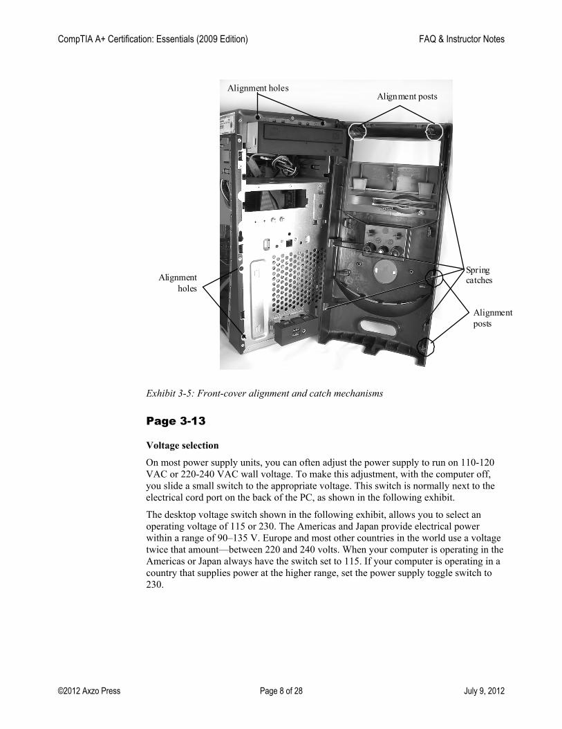
Alignment holes
Spring catches Alignment
holes
Alignment posts
Alignment posts
Exhibit 3-5: Front-cover alignment and catch mechanisms
Page 3-13
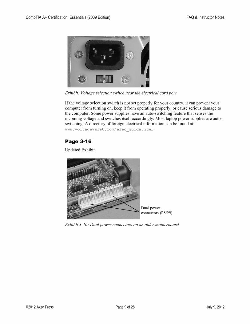
Voltage selection On most power supply units, you can often adjust the power supply to run on 110-120
VAC or 220-240 VAC wall voltage. To make this adjustment, with the computer off, you slide a small switch to the appropriate voltage. This switch is normally next to the electrical cord port on the back of the PC, as shown in the following exhibit.
The desktop voltage switch shown in the following exhibit, allows you to select an operating voltage of 115 or 230. The Americas and Japan provide electrical power within a range of 90–135 V. Europe and most other countries in the world use a voltage twice that amount—between 220 and 240 volts. When your computer is operating in the Americas or Japan always have the switch set to 115. If your computer is operating in a country that supplies power at the higher range, set the power supply toggle switch to 230.
CompTIA A+ Certification: Essentials (2009 Edition) FAQ & Instructor Notes
©2012 Axzo Press Page 9 of 28 July 9, 2012
Exhibit: Voltage selection switch near the electrical cord port
If the voltage selection switch is not set properly for your country, it can prevent your computer from turning on, keep it from operating properly, or cause serious damage to the computer. Some power supplies have an auto-switching feature that senses the incoming voltage and switches itself accordingly. Most laptop power supplies are auto-switching. A directory of foreign electrical information can be found at: www.voltagevalet.com/elec_guide.html.
Page 3-16 Updated Exhibit.
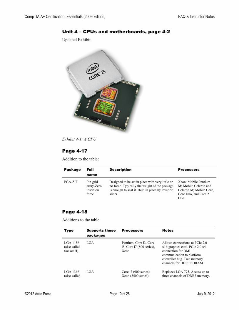
Dual power connectors (P8/P9)
Exhibit 3-10: Dual power connectors on an older motherboard
CompTIA A+ Certification: Essentials (2009 Edition) FAQ & Instructor Notes
©2012 Axzo Press Page 10 of 28 July 9, 2012
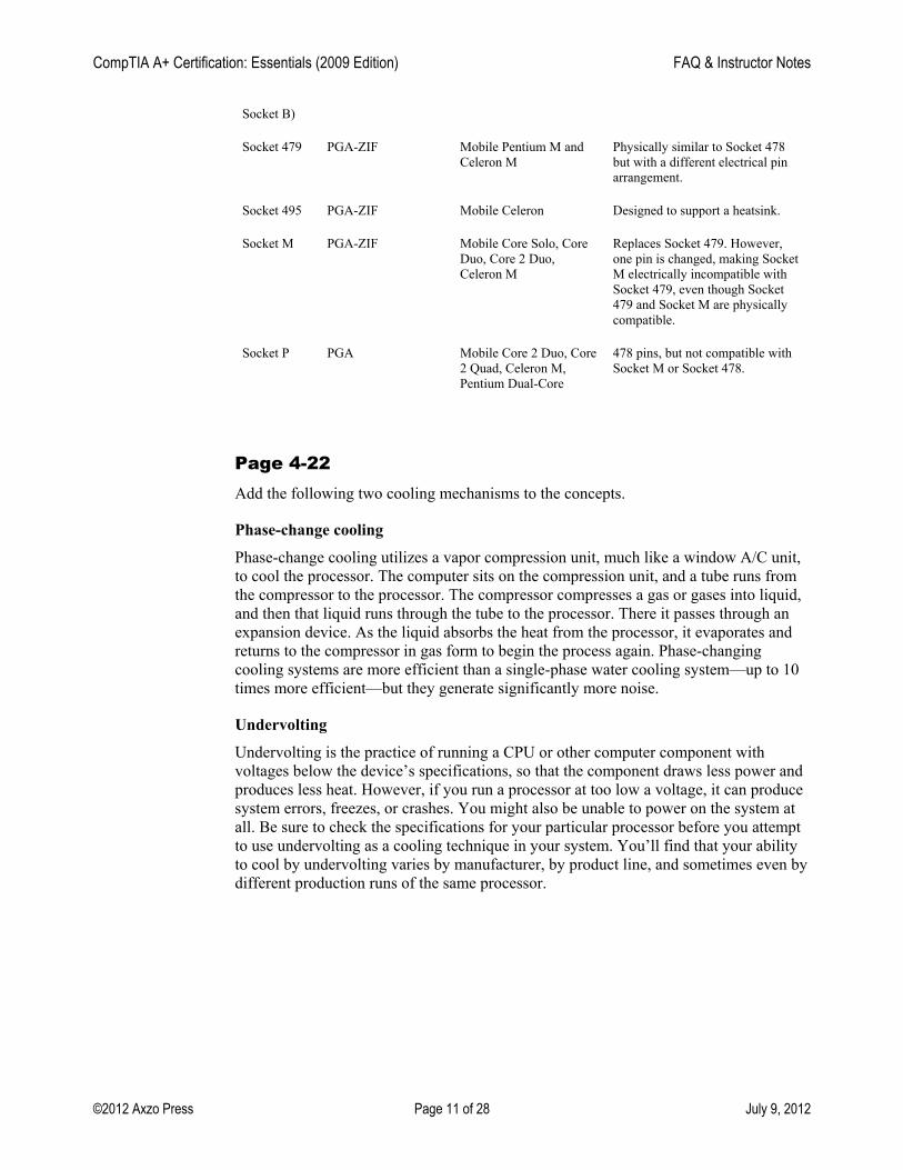
Unit 4 – CPUs and motherboards, page 4-2 Updated Exhibit.
Exhibit 4-1: A CPU
Page 4-17 Addition to the table:
Package Full name
Description Processors
PGA-ZIF Pin grid array-Zero insertion force
Designed to be set in place with very little or no force. Typically the weight of the package is enough to seat it. Held in place by lever or slider.
Xeon; Mobile Pentium M; Mobile Celeron and Celeron M; Mobile Core, Core Duo, and Core 2 Duo
Page 4-18 Additions to the table:
Type Supports these packages
Processors Notes
LGA 1156 (also called Socket H)
LGA Pentium, Core i3, Core i5, Core i7 (800 series), Xeon
Allows connections to PCIe 2.0 x16 graphics card. PCIe 2.0 x4 connection for DMI communication to platform controller hug. Two memory channels for DDR3 SDRAM.
LGA 1366 (also called
LGA Core i7 (900 series), Xeon (5500 series)
Replaces LGA 775. Access up to three channels of DDR3 memory.
CompTIA A+ Certification: Essentials (2009 Edition) FAQ & Instructor Notes
©2012 Axzo Press Page 11 of 28 July 9, 2012
Socket B)
Socket 479 PGA-ZIF Mobile Pentium M and Celeron M
Physically similar to Socket 478 but with a different electrical pin arrangement.
Socket 495 PGA-ZIF Mobile Celeron Designed to support a heatsink.
Socket M PGA-ZIF Mobile Core Solo, Core Duo, Core 2 Duo, Celeron M
Replaces Socket 479. However, one pin is changed, making Socket M electrically incompatible with Socket 479, even though Socket 479 and Socket M are physically compatible.
Socket P PGA Mobile Core 2 Duo, Core 2 Quad, Celeron M, Pentium Dual-Core
478 pins, but not compatible with Socket M or Socket 478.
Page 4-22 Add the following two cooling mechanisms to the concepts.
Phase-change cooling
Phase-change cooling utilizes a vapor compression unit, much like a window A/C unit, to cool the processor. The computer sits on the compression unit, and a tube runs from the compressor to the processor. The compressor compresses a gas or gases into liquid, and then that liquid runs through the tube to the processor. There it passes through an expansion device. As the liquid absorbs the heat from the processor, it evaporates and returns to the compressor in gas form to begin the process again. Phase-changing cooling systems are more efficient than a single-phase water cooling system—up to 10 times more efficient—but they generate significantly more noise.
Undervolting
Undervolting is the practice of running a CPU or other computer component with voltages below the device’s specifications, so that the component draws less power and produces less heat. However, if you run a processor at too low a voltage, it can produce system errors, freezes, or crashes. You might also be unable to power on the system at all. Be sure to check the specifications for your particular processor before you attempt to use undervolting as a cooling technique in your system. You’ll find that your ability to cool by undervolting varies by manufacturer, by product line, and sometimes even by different production runs of the same processor.
CompTIA A+ Certification: Essentials (2009 Edition) FAQ & Instructor Notes
©2012 Axzo Press Page 12 of 28 July 9, 2012
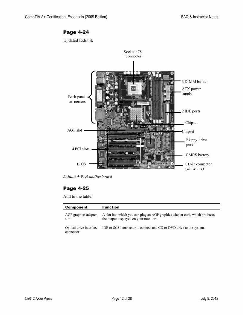
Page 4-24 Updated Exhibit.
Back panel connectors
Socket 478 connector
3 DIMM banks
ATX power supply
2 IDE ports
Chipset
Chipset
Floppy drive port
CMOS battery
BIOS
AGP slot
CD-in connector (white line)
4 PCI slots
Exhibit 4-9: A motherboard
Page 4-25 Add to the table:
Component Function
AGP graphics adapter slot
A slot into which you can plug an AGP graphics adapter card, which produces the output displayed on your monitor.
Optical drive interface connector
IDE or SCSI connector to connect and CD or DVD drive to the system.
CompTIA A+ Certification: Essentials (2009 Edition) FAQ & Instructor Notes
©2012 Axzo Press Page 13 of 28 July 9, 2012
Add after the table:
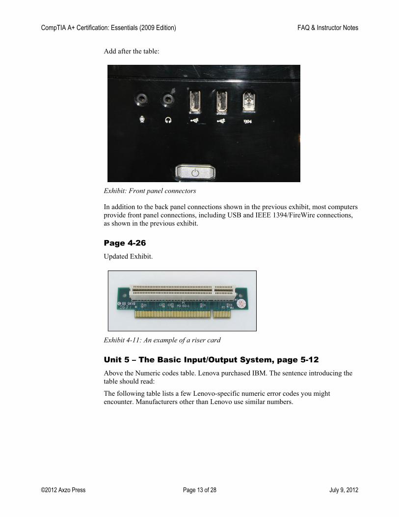
Exhibit: Front panel connectors
In addition to the back panel connections shown in the previous exhibit, most computers provide front panel connections, including USB and IEEE 1394/FireWire connections, as shown in the previous exhibit.
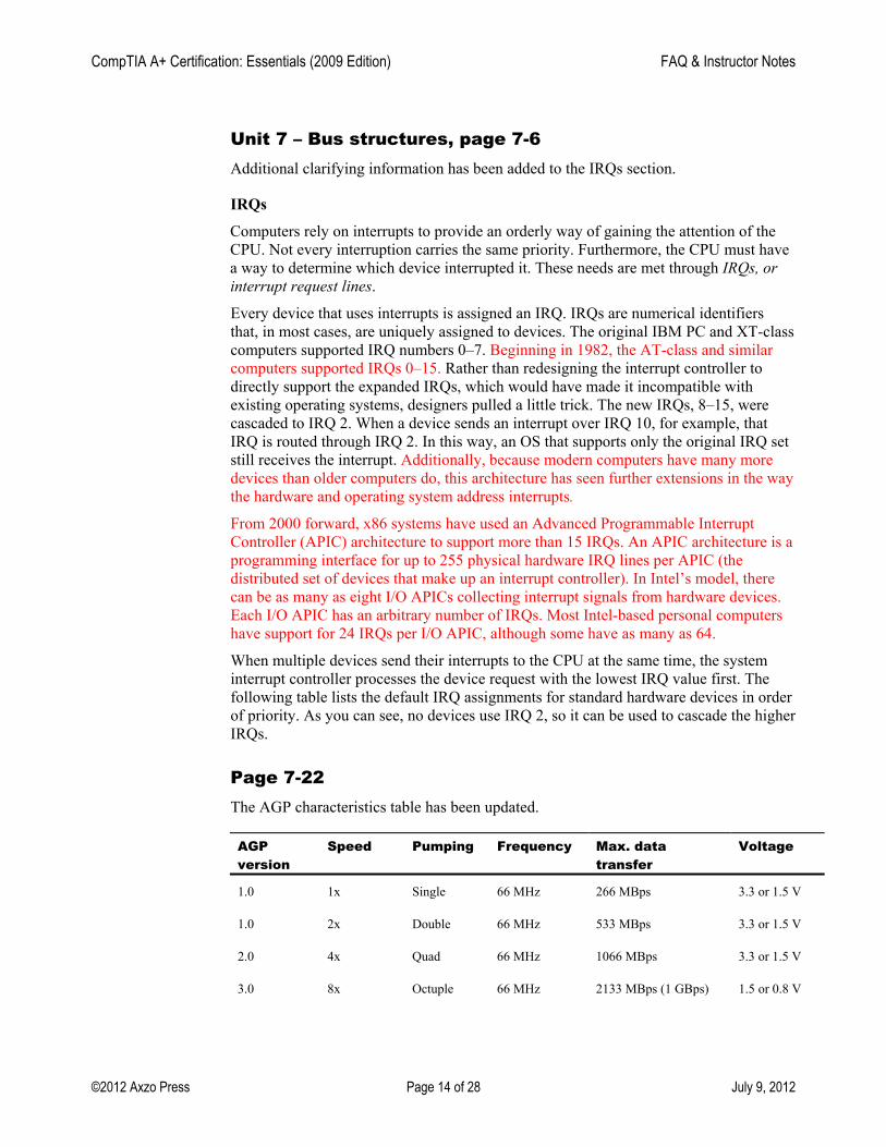
Page 4-26 Updated Exhibit.
Exhibit 4-11: An example of a riser card
Unit 5 – The Basic Input/Output System, page 5-12 Above the Numeric codes table. Lenova purchased IBM. The sentence introducing the table should read:
The following table lists a few Lenovo-specific numeric error codes you might encounter. Manufacturers other than Lenovo use similar numbers.
CompTIA A+ Certification: Essentials (2009 Edition) FAQ & Instructor Notes
©2012 Axzo Press Page 14 of 28 July 9, 2012
Unit 7 – Bus structures, page 7-6 Additional clarifying information has been added to the IRQs section.
IRQs Computers rely on interrupts to provide an orderly way of gaining the attention of the
CPU. Not every interruption carries the same priority. Furthermore, the CPU must have a way to determine which device interrupted it. These needs are met through IRQs, or interrupt request lines.
Every device that uses interrupts is assigned an IRQ. IRQs are numerical identifiers that, in most cases, are uniquely assigned to devices. The original IBM PC and XT-class computers supported IRQ numbers 0–7. Beginning in 1982, the AT-class and similar computers supported IRQs 0–15. Rather than redesigning the interrupt controller to directly support the expanded IRQs, which would have made it incompatible with existing operating systems, designers pulled a little trick. The new IRQs, 8–15, were cascaded to IRQ 2. When a device sends an interrupt over IRQ 10, for example, that IRQ is routed through IRQ 2. In this way, an OS that supports only the original IRQ set still receives the interrupt. Additionally, because modern computers have many more devices than older computers do, this architecture has seen further extensions in the way the hardware and operating system address interrupts.
From 2000 forward, x86 systems have used an Advanced Programmable Interrupt Controller (APIC) architecture to support more than 15 IRQs. An APIC architecture is a programming interface for up to 255 physical hardware IRQ lines per APIC (the distributed set of devices that make up an interrupt controller). In Intel’s model, there can be as many as eight I/O APICs collecting interrupt signals from hardware devices. Each I/O APIC has an arbitrary number of IRQs. Most Intel-based personal computers have support for 24 IRQs per I/O APIC, although some have as many as 64.
When multiple devices send their interrupts to the CPU at the same time, the system interrupt controller processes the device request with the lowest IRQ value first. The following table lists the default IRQ assignments for standard hardware devices in order of priority. As you can see, no devices use IRQ 2, so it can be used to cascade the higher IRQs.
Page 7-22 The AGP characteristics table has been updated.
AGP
version Speed Pumping Frequency Max. data
transfer Voltage
1.0 1x Single 66 MHz 266 MBps 3.3 or 1.5 V
1.0 2x Double 66 MHz 533 MBps 3.3 or 1.5 V
2.0 4x Quad 66 MHz 1066 MBps 3.3 or 1.5 V
3.0 8x Octuple 66 MHz 2133 MBps (1 GBps) 1.5 or 0.8 V
CompTIA A+ Certification: Essentials (2009 Edition) FAQ & Instructor Notes
©2012 Axzo Press Page 15 of 28 July 9, 2012
Unit 8 – Expansion cards, page 8-12 The USB and IEE 1394/Firewire information as it pertains to drive adapters has been updated.
USB USB is not a drive interface, but instead a general purpose data bus. Most USB drives
are actually ATA drives with an integrated USB interface adapter. While this is certainly a convenient way to attach an external ATA drive to your PC, it’s not the same as connecting a drive directly to the USB interface.
True USB drives are feasible. The circuitry of the drive would be connected directly to the USB bus without any sort of ATA controller involved. Hard drives with this configuration are rare, perhaps non-existent. However, the typical USB flash drive or memory card reader is just such a drive. Circuitry in these devices translates directly from the memory card’s electrical interface to the USB bus. No ATA/PATA controller is involved in most USB flash drive designs.
USB flash drives implement the USB mass storage device class (UMS), which is a set of communications protocols defined by the USB Implementers Forum. UMS enables operating systems to access storage devices via the USB bus. UMS is supported in Windows since the Windows 98 days. It is also supported by Mac OS X and Linux.
UMS doesn’t support the full range of low-level hard drive functions, such as S.M.A.R.T., command-queuing, and so forth. For USB flash drives, this is typically not a concern. External hard drives in a USB enclosure might be a PATA drive internally. But, because they connect to the PC via the UMS interface, they are likewise unable to take advantage of these advanced low-level functions.
The USB 1.1 specification limited data transfer to 12 Mbps (megabits per second). The USB 2.0 specification increased that limit to 480 Mbps. The USB 3.0 specification has a maximum transfer speed of 5 Gbps.
IEEE 1394 / FireWire IEEE 1394 is a serial interface technology based on the Serial SCSI standard. It’s a
general-purpose interface. As with USB, it’s possible to use FireWire in place of a more traditional drive interface. Akin to USB’s UMS standard, IEEE 1394 uses the Serial Bus Protocol 2 (SBP-2) to enable the operating system to interface directly with storage devices without a traditional drive interface involved.
FireWire 400 supports up to 400 Mbps throughput, while FireWire 800 supports up to 800 Mbps. FireWire S1600, with a data transfer rate of 1.6 Gbps; and FireWire S3200, with a data transfer rate of 4 Gbps are newer versions designed to compete with the new USB 3.0 standard.
FireWire supports isochronous transfers in which a device can be granted dedicated access to the interface for a period of time. This makes FireWire well-suited for video data, whether it be as a stream of digital video from a camera or a stream of digitized video read from a fast disk drive or array.
CompTIA A+ Certification: Essentials (2009 Edition) FAQ & Instructor Notes
©2012 Axzo Press Page 16 of 28 July 9, 2012
Unit 9 – Peripheral connection types, page 9-6 Additional information regarding serial cables.
Serial cables Standard serial cables come in the following types:
• EIA/TIA-232 • EIA/TIA-449 • V.35 • X.21 • EIA/TIA-530
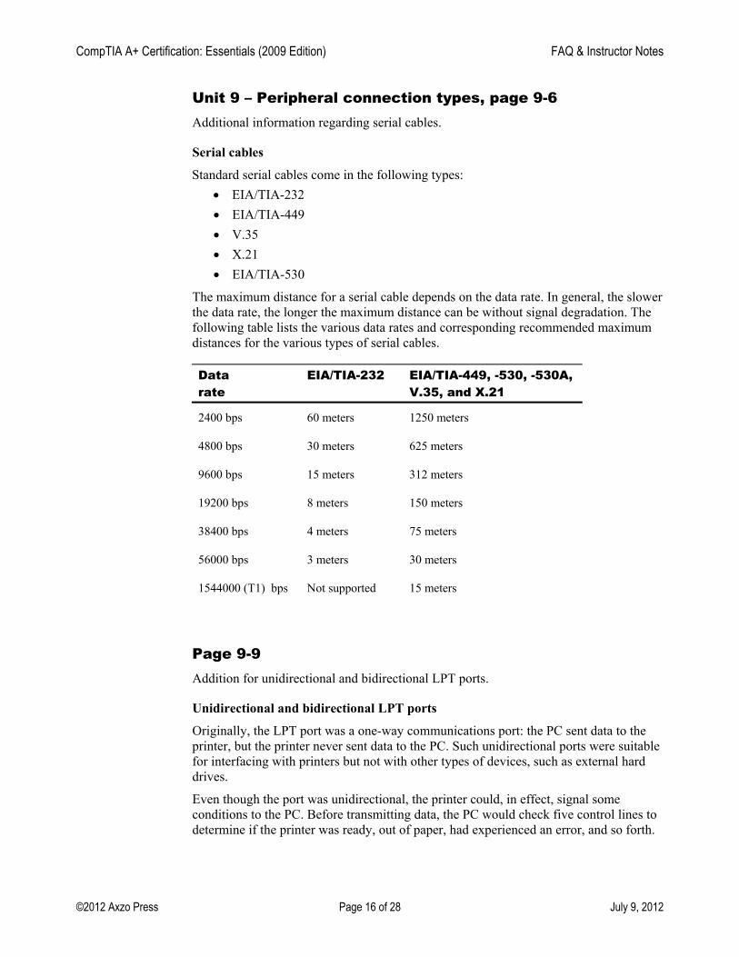
The maximum distance for a serial cable depends on the data rate. In general, the slower the data rate, the longer the maximum distance can be without signal degradation. The following table lists the various data rates and corresponding recommended maximum distances for the various types of serial cables.
Data rate
EIA/TIA-232 EIA/TIA-449, -530, -530A, V.35, and X.21
2400 bps 60 meters 1250 meters
4800 bps 30 meters 625 meters
9600 bps 15 meters 312 meters
19200 bps 8 meters 150 meters
38400 bps 4 meters 75 meters
56000 bps 3 meters 30 meters
1544000 (T1) bps Not supported 15 meters
Page 9-9 Addition for unidirectional and bidirectional LPT ports.
Unidirectional and bidirectional LPT ports
Originally, the LPT port was a one-way communications port: the PC sent data to the printer, but the printer never sent data to the PC. Such unidirectional ports were suitable for interfacing with printers but not with other types of devices, such as external hard drives.
Even though the port was unidirectional, the printer could, in effect, signal some conditions to the PC. Before transmitting data, the PC would check five control lines to determine if the printer was ready, out of paper, had experienced an error, and so forth.
CompTIA A+ Certification: Essentials (2009 Edition) FAQ & Instructor Notes
©2012 Axzo Press Page 17 of 28 July 9, 2012
The original LPT port specifications were developed largely by the Centronics Corporation, thus the port is often called the Centronics port. Few modern printers support this old unidirectional parallel port mode.
A group called the Network Printing Alliance formed to improve the functionality of the LPT port. Their work resulted in the IEEE 1284 standard, which defines five modes of operation:
• Compatibility mode—also called standard parallel port (SPP) mode. This mode provided backward compatibility with Centronics-compatible printers.
• Nibble mode, which is a unidirectional mode that enables the printer to transmit four bits of data (a “nibble”) over the status lines. This communication sent additional status information to the PC.
• Byte mode, which is similar to nibble mode, except that eight bits of status data can be transmitted over the status lines.
• Enhanced parallel port (EPP) is a half-duplex bidirectional mode supporting data transmission of up to 2 MB per second.
• Extended capabilities port (ECP) is a half-duplex bidirectional mode supporting data transmission of up to 2.5 MB per second.
The EPP and ECP modes enabled two-way communication across the parallel port. This development enabled manufactures to create devices, such as external hard drives or data transfer cables (like the once popular LapLink cable), that operated over the parallel port. These modes supported data transfer rates nearly equal to the ISA expansion bus, which was the most popular type when these modes were first defined.
Modern PCs typically support each of these modes. You might need to use the BIOS setup utility to enable or disable specific modes.
Page 9-25 Clarification on the Notes column for USB 3.0:
USB 3.0 Supports USB 1.1 and 2.0 rates
Adds SuperSpeed mode, with up to 5.0 Gbps
Uses slightly different plugs and sockets that are upwardly compatible. The means you can plug a USB 1.1 or 2.0 cable into a USB 3.0 socket. It will not fit in all the way, making contact with only the pins necessary to provide USB 1.1 or 2.0 connectivity. However, a USB 3.0 cable will not fit into an older style socket.
Full-duplex, meaning that it can upload and download simultaneously (it’s bidirectional).
Updated Exhibit to include USB 3.0 labels:
Exhibit : USB 3.0 labels
CompTIA A+ Certification: Essentials (2009 Edition) FAQ & Instructor Notes
©2012 Axzo Press Page 18 of 28 July 9, 2012
Page 9-34 Clarification on the 1/8” connector:
The TRS jack
Officially known as the TRS (Tip, Ring, and Sleeve) jack, the mini-stereo or audio jack is used to connect speakers, microphones, headphones, and other audio devices. The TRS jack has three contacts (the tip, ring, and sleeve). Variations include the two-contact TS and four-contact TRRS jacks.
Various sizes exist, but the most common are 1/4”, 1/8” (officially 3.5 mm), and 3/32” (officially 2.5 mm) sizes. The 1/4” size is rarely used with computers. The 2.5 mm size is more common with MP3 players and other small devices.
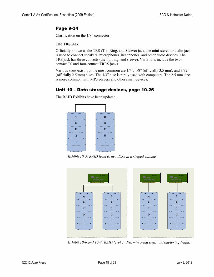
Unit 10 – Data storage devices, page 10-25 The RAID Exhibits have been updated.
Exhibit 10-5: RAID level 0, two disks in a striped volume
Exhibit 10-6 and 10-7: RAID level 1, disk mirroring (left) and duplexing (right)
CompTIA A+ Certification: Essentials (2009 Edition) FAQ & Instructor Notes
©2012 Axzo Press Page 19 of 28 July 9, 2012
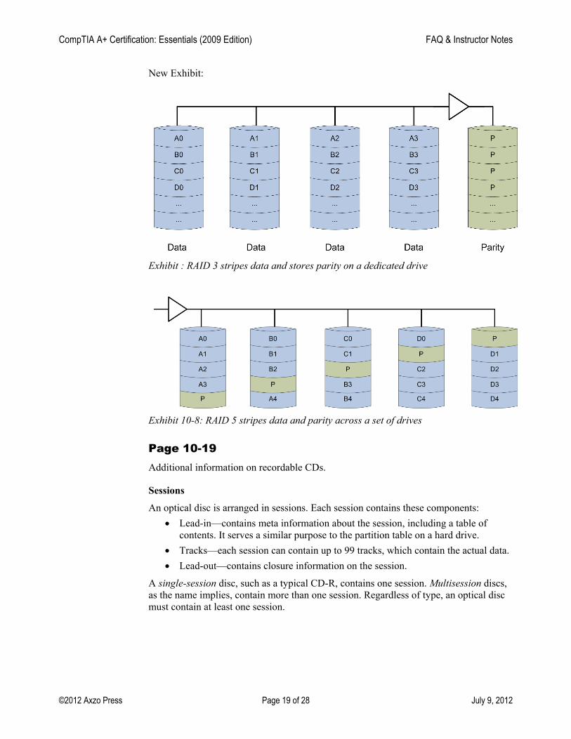
New Exhibit:
Exhibit : RAID 3 stripes data and stores parity on a dedicated drive
Exhibit 10-8: RAID 5 stripes data and parity across a set of drives
Page 10-19 Additional information on recordable CDs.
Sessions
An optical disc is arranged in sessions. Each session contains these components: • Lead-in—contains meta information about the session, including a table of
contents. It serves a similar purpose to the partition table on a hard drive. • Tracks—each session can contain up to 99 tracks, which contain the actual data. • Lead-out—contains closure information on the session.
A single-session disc, such as a typical CD-R, contains one session. Multisession discs, as the name implies, contain more than one session. Regardless of type, an optical disc must contain at least one session.
CompTIA A+ Certification: Essentials (2009 Edition) FAQ & Instructor Notes
©2012 Axzo Press Page 20 of 28 July 9, 2012
Page 10-20 Additional information on file systems and formats for CDs.
File systems and formats CDs can store either digital computer data or audio information. These data types are
stored using different formats. Data is stored using the ISO 9660 file system, also known as CDFS (Compact Disc File System). ISO 9660 (CDFS) is supported by many operating systems, including Windows, Macintosh, and most Linux versions.
Audio CDs are recorded in the Compact Disc Digital Audio (CD-DA) format. CD-DA is a two-channel (stereo) 16-bit PCM encoded format with a 44.1 kHz sampling rate per channel. Monaural (mono) sound is not officially included in the standard; typically, mono recordings are stored in a single channel or both channels store matching copies of the mono audio.
Page 10-21 Additional information on Blu-ray discs.
Blu-ray discs The Blu-ray disc was developed by the Blu-ray Disc Association, a group of
representatives from consumer electronics manufacturers, computer hardware manufacturers, and the motion picture industry. The Blu-ray standards were finalized in 2004.
Blu-ray discs are optical discs created with a “blue” (actually, violet) 405 nm laser. Because of the violet laser’s shorter wavelength, standard dual-layer Blu-ray 12cm discs hold up to 50 GB of data, and single-layer Blu-ray discs hold up to 25 GB of data. This capacity is significantly higher than a DVD’s capacity. It’s important to note that the Blu-ray specifications don’t indicate a maximum upper storage limit. There are less common higher capacity discs available such as:
• Quad-layer (100 GB) discs consisting of four layers containing 25 GB each • Discs that can hold 200 GB of data on a single side, using six 33 GB data layers. • 400 GB discs containing 16 data layers of 25 GB each • Hybrid discs that contain both Blu-ray and DVD layers on the same side of the
disc. For example, Infinity’s Code Blue disk contains a single Blu-ray Disc layer (25 GB) and two standard DVD layers (9 GB) on the same side of the disc
Some of the higher capacity discs require special equipment or firmware to be read. Currently, Blu-ray discs are primarily used to store high-definition video or large amounts of data.
Blu-ray discs are also available in a mini size of 8cm designed for use in consumer electronic equipment, such as camcorders. The mini-Blu-ray single-layer discs hold up to 7.8 GB of data, and the double-layer discs hold up to 15.6 GB.
CompTIA A+ Certification: Essentials (2009 Edition) FAQ & Instructor Notes
©2012 Axzo Press Page 21 of 28 July 9, 2012
Blu-ray recordable
There are two types of recordable Blu-ray media: • BD-R discs can be written once • BD-RE can be erased and rerecorded multiple times
The maximum recording speed for Blu-ray discs is currently 12×. This isn’t as high as a standard DVD’s 20x or 25x, because the higher speeds of rotation cause too much wobble for Blu-ray discs to be read properly.
Unit 11 – Video output and image input devices, page 11-13 Clarification on the Capacitors bullet:
• Capacitors — Capacitors are placed between layers over the screen. A touch changes the charge in the capacitors, and this change in charge is used by the controller to calculate the location of the touch.
Page 11-15 Correction on the DVI-I Description:
DVI-I supports both digital and analog signals. The DVI-I connector contains four more pins than a DVI-D connector contains. These four pins carry analog signals. The analog signal pins are located above and below the grounding slot.
Unit 12 – Printers, page 12-22
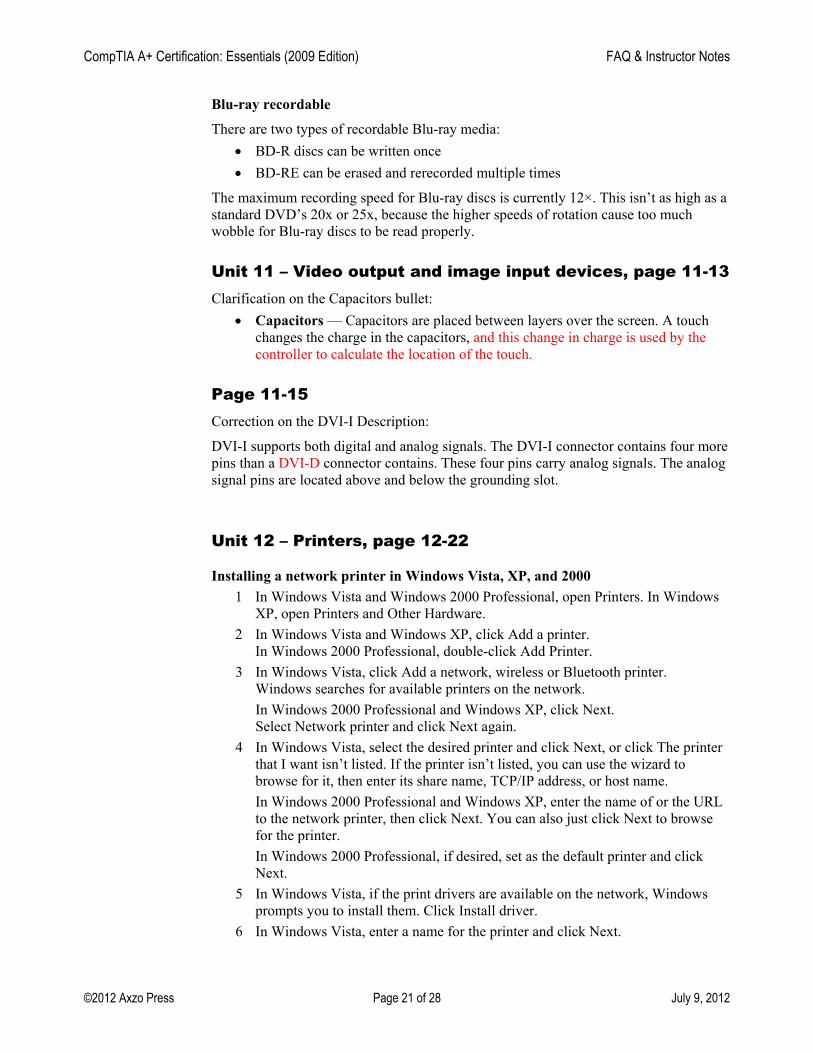
Installing a network printer in Windows Vista, XP, and 2000 1 In Windows Vista and Windows 2000 Professional, open Printers. In Windows
XP, open Printers and Other Hardware. 2 In Windows Vista and Windows XP, click Add a printer.
In Windows 2000 Professional, double-click Add Printer. 3 In Windows Vista, click Add a network, wireless or Bluetooth printer.
Windows searches for available printers on the network. In Windows 2000 Professional and Windows XP, click Next.
Select Network printer and click Next again. 4 In Windows Vista, select the desired printer and click Next, or click The printer
that I want isn’t listed. If the printer isn’t listed, you can use the wizard to browse for it, then enter its share name, TCP/IP address, or host name.
In Windows 2000 Professional and Windows XP, enter the name of or the URL to the network printer, then click Next. You can also just click Next to browse for the printer.
In Windows 2000 Professional, if desired, set as the default printer and click Next.
5 In Windows Vista, if the print drivers are available on the network, Windows prompts you to install them. Click Install driver.
6 In Windows Vista, enter a name for the printer and click Next.
CompTIA A+ Certification: Essentials (2009 Edition) FAQ & Instructor Notes
©2012 Axzo Press Page 22 of 28 July 9, 2012
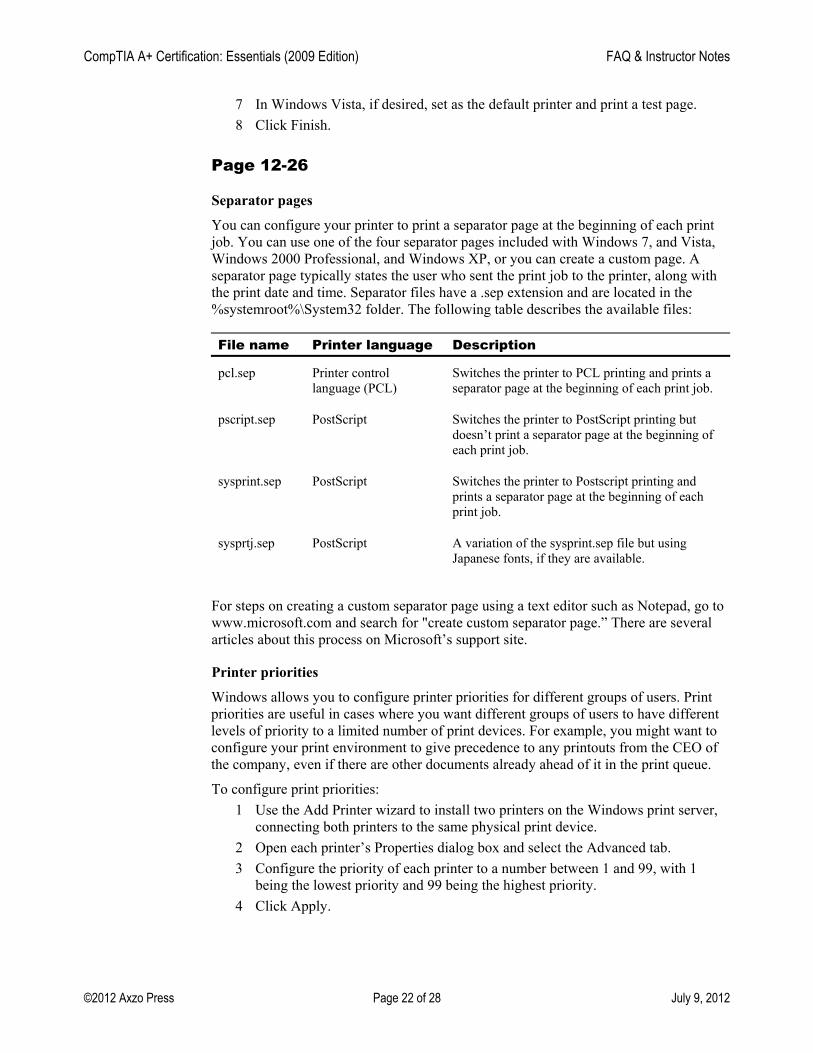
7 In Windows Vista, if desired, set as the default printer and print a test page. 8 Click Finish.
Page 12-26
Separator pages
You can configure your printer to print a separator page at the beginning of each print job. You can use one of the four separator pages included with Windows 7, and Vista, Windows 2000 Professional, and Windows XP, or you can create a custom page. A separator page typically states the user who sent the print job to the printer, along with the print date and time. Separator files have a .sep extension and are located in the %systemroot%\System32 folder. The following table describes the available files:
File name Printer language Description
pcl.sep Printer control language (PCL)
Switches the printer to PCL printing and prints a separator page at the beginning of each print job.
pscript.sep PostScript Switches the printer to PostScript printing but doesn’t print a separator page at the beginning of each print job.
sysprint.sep PostScript Switches the printer to Postscript printing and prints a separator page at the beginning of each print job.
sysprtj.sep PostScript A variation of the sysprint.sep file but using Japanese fonts, if they are available.
For steps on creating a custom separator page using a text editor such as Notepad, go to www.microsoft.com and search for "create custom separator page.” There are several articles about this process on Microsoft’s support site.
Printer priorities Windows allows you to configure printer priorities for different groups of users. Print
priorities are useful in cases where you want different groups of users to have different levels of priority to a limited number of print devices. For example, you might want to configure your print environment to give precedence to any printouts from the CEO of the company, even if there are other documents already ahead of it in the print queue.
To configure print priorities: 1 Use the Add Printer wizard to install two printers on the Windows print server,
connecting both printers to the same physical print device. 2 Open each printer’s Properties dialog box and select the Advanced tab. 3 Configure the priority of each printer to a number between 1 and 99, with 1
being the lowest priority and 99 being the highest priority. 4 Click Apply.
CompTIA A+ Certification: Essentials (2009 Edition) FAQ & Instructor Notes
©2012 Axzo Press Page 23 of 28 July 9, 2012
Continue in Windows 7 and Vista and Windows 2000 Professional (not available in Windows XP):
5 Select the Security tab. 6 Restrict the higher priority printer to the users or groups you want to have
priority access to the printer. 7 Click OK.
Troubleshooting If the printer is online, and you can print a test page from the printer’s Properties dialog
box in Windows. • If the test page prints from the Properties dialog box, you can stop
troubleshooting the printer, the connection, the operating system, and the drivers. Go back and troubleshoot the application and verify that the application settings aren’t conflicting with the driver settings.
• If the test page doesn’t print from the Properties dialog box, try these options: – Use the printer’s Properties dialog box to verify that the most current
version of the correct driver is installed. If necessary, update the driver, or uninstall and then reinstall the drivers. This will resolve problems with incorrect drivers.
– Verify the driver port settings, using the printer’s Properties dialog box. – Verify that the printer driver supports any accessories and options, such as
duplex printing, that are configured for the print job. – Check the Windows event logs for any error messages related to printing.
Verify that the print spool isn’t stalled.
Sometimes a print job will stall as it is spooling, preventing it or any documents behind it in the queue from printing. In the print queue, you’ll see the job listed as "Spooling.” Unfortunately, there typically isn’t any error message that tells you the print job has stalled. It simply sits in the print queue listed as spooling. If this happens, right-click the job that’s stalled and choose Cancel Printing. Try reprinting the job. Remember that documents with graphics take longer to print than text documents, so make sure the document is stalled and not just processing the graphics.
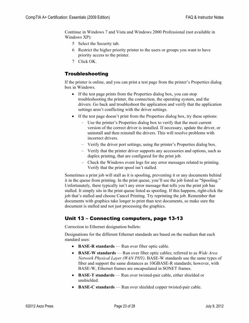
Unit 13 – Connecting computers, page 13-13 Correction to Ethernet designation bullets:
Designations for the different Ethernet standards are based on the medium that each standard uses:
• BASE-R standards — Run over fiber optic cable. • BASE-W standards — Run over fiber optic cables; referred to as Wide Area
Network Physical Layer (WAN PHY). BASE-W standards use the same types of fiber and support the same distances as 10GBASE-R standards; however, with BASE-W, Ethernet frames are encapsulated in SONET frames.
• BASE-T standards — Run over twisted-pair cable, either shielded or unshielded.
• BASE-C standards — Run over shielded copper twisted-pair cable.
CompTIA A+ Certification: Essentials (2009 Edition) FAQ & Instructor Notes
©2012 Axzo Press Page 24 of 28 July 9, 2012
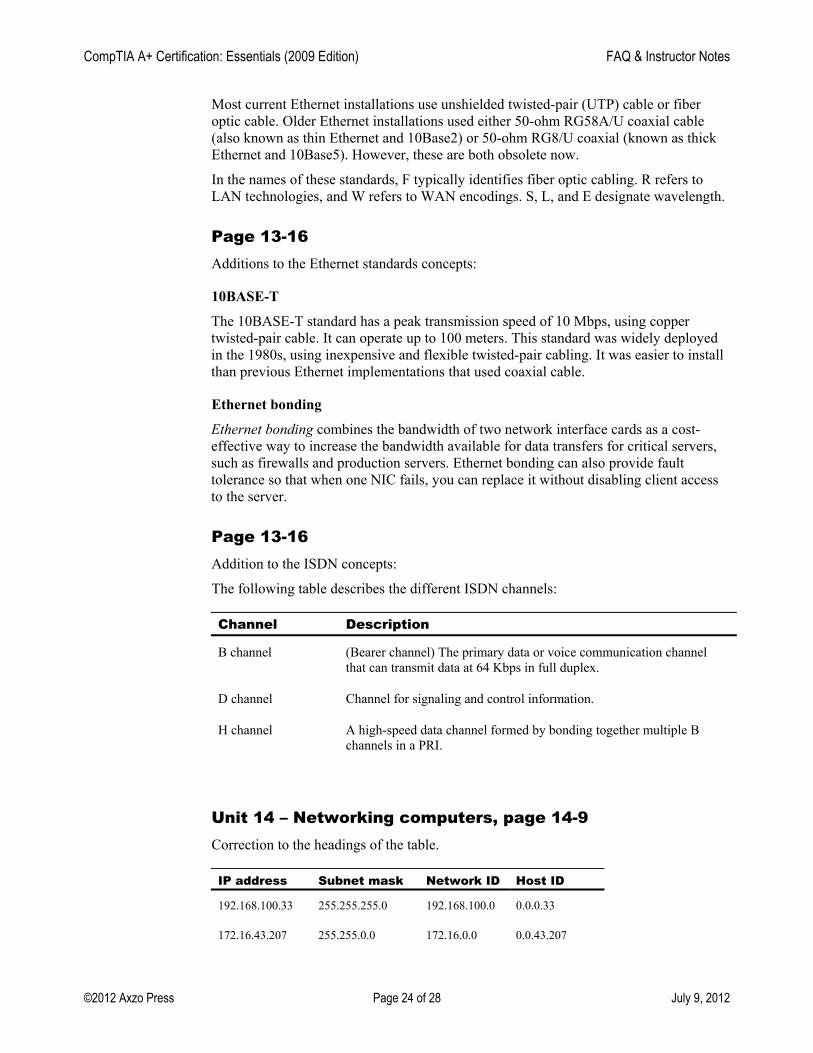
Most current Ethernet installations use unshielded twisted-pair (UTP) cable or fiber optic cable. Older Ethernet installations used either 50-ohm RG58A/U coaxial cable (also known as thin Ethernet and 10Base2) or 50-ohm RG8/U coaxial (known as thick Ethernet and 10Base5). However, these are both obsolete now.
In the names of these standards, F typically identifies fiber optic cabling. R refers to LAN technologies, and W refers to WAN encodings. S, L, and E designate wavelength.
Page 13-16 Additions to the Ethernet standards concepts:
10BASE-T The 10BASE-T standard has a peak transmission speed of 10 Mbps, using copper
twisted-pair cable. It can operate up to 100 meters. This standard was widely deployed in the 1980s, using inexpensive and flexible twisted-pair cabling. It was easier to install than previous Ethernet implementations that used coaxial cable.
Ethernet bonding Ethernet bonding combines the bandwidth of two network interface cards as a cost-
effective way to increase the bandwidth available for data transfers for critical servers, such as firewalls and production servers. Ethernet bonding can also provide fault tolerance so that when one NIC fails, you can replace it without disabling client access to the server.
Page 13-16 Addition to the ISDN concepts:
The following table describes the different ISDN channels: Channel Description
B channel (Bearer channel) The primary data or voice communication channel that can transmit data at 64 Kbps in full duplex.
D channel Channel for signaling and control information.
H channel A high-speed data channel formed by bonding together multiple B channels in a PRI.
Unit 14 – Networking computers, page 14-9 Correction to the headings of the table.
IP address Subnet mask Network ID Host ID
192.168.100.33 255.255.255.0 192.168.100.0 0.0.0.33
172.16.43.207 255.255.0.0 172.16.0.0 0.0.43.207
CompTIA A+ Certification: Essentials (2009 Edition) FAQ & Instructor Notes
©2012 Axzo Press Page 25 of 28 July 9, 2012
Page 14-44 Additional information for wireless client configuration.
RADIUS servers When you implement an authenticating server, such as RADIUS, the wireless client
must submit its credentials to the authenticating server before wireless network access is established. When the client computer is in range of the wireless AP, it tries to connect to the WLAN that is active on the wireless AP. If the wireless AP is configured to allow only secured or 802.1x-authenticated connections, it issues a challenge to the client. The wireless AP then sets up a restricted channel that allows the client to communicate with only the RADIUS server.
The RADIUS server accepts a connection only from only two sources: a trusted wireless AP; or a WAP that has been configured as a RADIUS client on the Microsoft Internet Authentication Service (IAS) server and that provides the shared secret key for that RADIUS client.
The RADIUS server validates the client credentials against the directory. If the client is successfully authenticated, the RADIUS server decides whether to authorize the client to use the WLAN. If the client is granted access, the RADIUS server transmits the client master key to the wireless AP. The client and wireless AP now share common key information they can use to encrypt and decrypt the WLAN traffic passing between them. How you configure clients to participate in this process depends on the operating system.
Unit 15 – Portable computers, page 15-6 Additional concepts for power:
Auto-switching Notebook computers have the ability to switch between the battery and the AC power
supply automatically. When the AC power supply is connected to the notebook and an external power supply, the notebook computer runs on the power supplied by the external source. When you unplug the AC power supply from the notebook computer or from the external power source, the notebook computer automatically switches to battery power. The notebook continues to run on battery power until the battery is fully discharged or you reconnect the notebook to an external power supply. The operating system on the notebook monitors the power remaining in the battery and displays warnings as the power reaches low levels. This allows you either to save your work and shut down the computer or to connect the notebook to an external power supply.
CompTIA A+ Certification: Essentials (2009 Edition) FAQ & Instructor Notes
©2012 Axzo Press Page 26 of 28 July 9, 2012
Page 15-8 Additional concepts for Wireless networks:
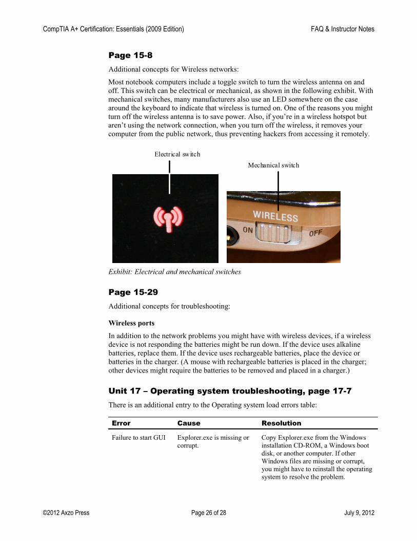
Most notebook computers include a toggle switch to turn the wireless antenna on and off. This switch can be electrical or mechanical, as shown in the following exhibit. With mechanical switches, many manufacturers also use an LED somewhere on the case around the keyboard to indicate that wireless is turned on. One of the reasons you might turn off the wireless antenna is to save power. Also, if you’re in a wireless hotspot but aren’t using the network connection, when you turn off the wireless, it removes your computer from the public network, thus preventing hackers from accessing it remotely.
Electrical switch
Mechanical switch
Exhibit: Electrical and mechanical switches
Page 15-29 Additional concepts for troubleshooting:
Wireless ports
In addition to the network problems you might have with wireless devices, if a wireless device is not responding the batteries might be run down. If the device uses alkaline batteries, replace them. If the device uses rechargeable batteries, place the device or batteries in the charger. (A mouse with rechargeable batteries is placed in the charger; other devices might require the batteries to be removed and placed in a charger.)
Unit 17 – Operating system troubleshooting, page 17-7 There is an additional entry to the Operating system load errors table:
Error Cause Resolution
Failure to start GUI Explorer.exe is missing or corrupt.
Copy Explorer.exe from the Windows installation CD-ROM, a Windows boot disk, or another computer. If other Windows files are missing or corrupt, you might have to reinstall the operating system to resolve the problem.
CompTIA A+ Certification: Essentials (2009 Edition) FAQ & Instructor Notes
©2012 Axzo Press Page 27 of 28 July 9, 2012
Unit 18 – Security, page 18-39 Additional concepts for malicious software:
Phishing Phishing, a growing problem on the Internet, is an example of a social engineering
attack. In phishing, hackers send e-mail messages or create Web sites that mimic a legitimate site to gather usernames and passwords. For example, an e-mail message might purport to come from a person’s bank and request the user to log onto a Web site to perform account maintenance. In reality, the Web site would simply collect the person’s username and password and present fake messages about the account maintenance. Later, the hackers would drain the person’s account by logging into the bank’s real Web site.
Unit 19 – Windows installation and upgrades, page 19-3 Additional concepts for installing Windows operating systems:
Multibooting A less common installation option is to install your chosen version of Windows, along
with another operating system or version of Windows, allowing the computer to be booted into either operating system. As a general rule, you install the operating systems oldest to newest. For example, you would install Windows XP before Windows 7, Windows Vista, or Windows 2000 Professional. Each operating system must be placed in a separate hard disk partition on a non-dynamic disk.
CompTIA A+ Certification: Essentials (2009 Edition) FAQ & Instructor Notes
©2012 Axzo Press Page 28 of 28 July 9, 2012
Unit 20 – Safety, page 20-6 Additional concepts for Physical hazards:
It’s also important to restrain or remove neckties, loose clothing, dangling jewelry, and long hair so that such things don’t become entangled with components.
The electronic components of computers generate heat. Many times the heat generated by these components is enough to cause a serious burn if they’re touched. For example, while a notebook computer is often referred to as a “laptop,” if placed on your lap covering the bottom air vents, you’ll find that, after a while, the heat becomes quite uncomfortable and can actually burn your skin. If you’ll be working with a notebook computer on your lap, it’s best to purchase a lap desk. These allow air to circulate through the air vents on the bottom of the notebook as if on a desk.
They also protect your skin from the hot air moving away from the components. You should exercise caution working on the internal components of a computer, as they can retain heat. Even if you aren’t working on a component that generates heat itself, you are working in close quarters and can accidently brush up against a component that is hot.
Additional concepts for Laser printer and copier toner:
The charged corona wire in a laser printer creates ozone, an air pollutant capable of causing respiratory illness. To keep the concentrations of ozone below the currently regulated standard, many newer laser printers employ replaceable ozone filters. Make sure you follow the manufacturer’s instructions for replacing the ozone filter at proper intervals to protect against unsafe levels of ozone emissions.
Topic D: Additional information There is no additional information for this course at this time.