Embed Size (px)
Citation preview
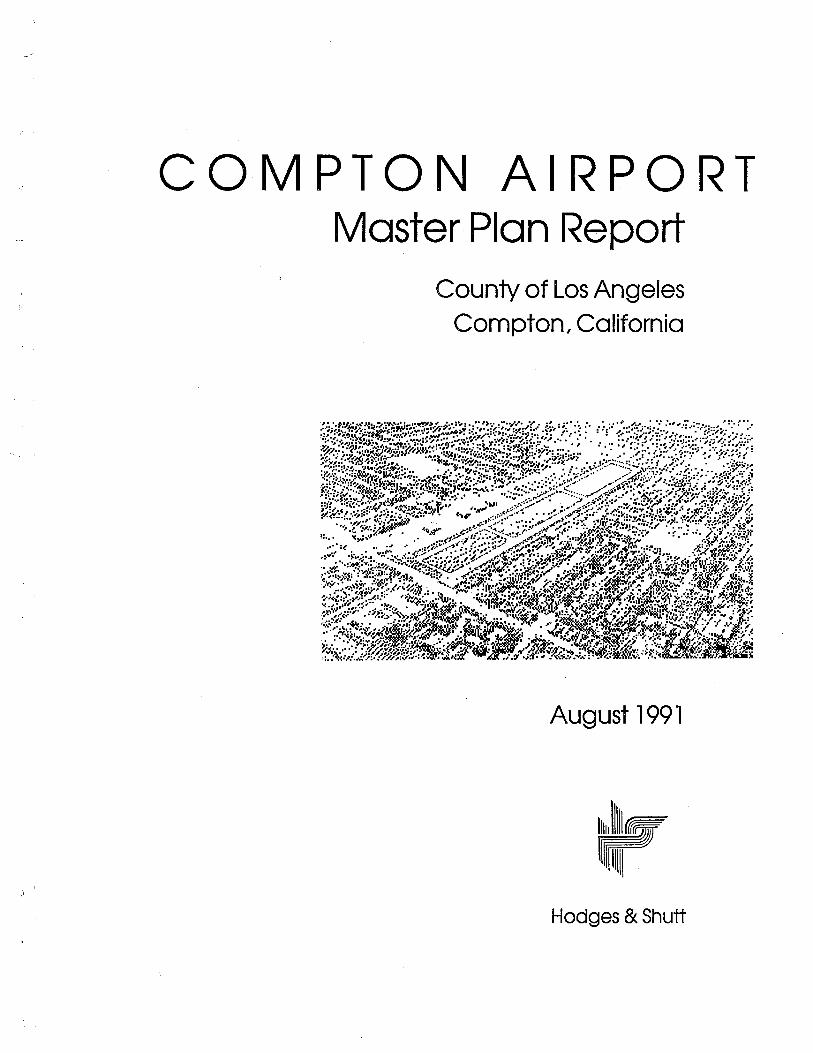
COMPTON AIRPORTMaster Plan Report
County of Los AngelesCompton, California
August 1991
trHodges & Shutt
COMPTON AIRPORTMaster Plan Report
County of Los AngelesCompton, California
Preparedby
HODGES & SHUTTfor the
COUNTY of LOS ANGELESDepartment of Public Works
Aviation Division
August 1991
COUNTY OF LOS ANGELES
Board of Supervisors
Michael D. Antonovich, ChairmanDeane Dana
Edmund D. EdelmanKenneth HahnGloria Molina
Aviation Commission
Lester E. Benson, ChairmanAngelo R. Cardono, Vice ChairmanRoger L. Persons, SecretaryClyde C. BaileyDonald l. BohanaNini Cutter
Jan Charles GrayJames M. Woods
Staff
Ted A. Gustin, Chief, Aviation DivisionJames H. Abing, Project Manager
EFFECTIVE APRIL 1, 1991, COMPTON AIRPORT IS OPERATED UNDER THE TERMS OF AMANAGEMENT SERVICES AGREEMENT BETWEEN THE COUNTY OF LOS ANGELES (OWNER)AND COMARCO, INC. (AGENT).
The preparation of this document was financed in part through a planning grant from the FederalAviation Administration (FAA) as provided under Section 505 of the Airport and Airway Improve-ment Act of 1982, as amended. The contents of this report reflect the views of Hodges & Shutt,who are responsible for the facts and accuracy of the data presented herein. The contents do notnecessarily reflect the official views of the FAA. Acceptance of this report by the FAA does not inany way constitute a commitment on the part of the United States to participate in any develop-ment depicted herein, no does it indicate that the proposed development is environmentally accept-able in acordance with Public Laws 91-190, 91-258, and/or 90-495.
~
l
Table of ContentsPageNo.
1 - INTRODUCTIONSTUDY BACKGROUND ................................................ 1CONTENTS OF THE PLAN. . . . . . . . . . . . . . . . . . . . . . . . . . . . . . . . . . . . . . . . . . . . .. 1
2 - SUMMARYOVERVIEW... .... .. ... . ... ... .. .. ...... .... .......... .... . .. . . .. . .. 3
PLAN DRAWINGS .................................................... 4BACKGROUND AND INVENTORY ........................................ 5AIRPORT ACTIVITY AND CAPACITY ANALYSIS .................;............. 5
Historical Airport Activity ............................................ 6
Activity Forecasts . . . . . . . . . . . . . . . . . . . . . . . . . . . . . . . . . . . . . . . . . . . . . . . . . .. 6Capacity Analysis . . . . . . . . . . . . . . . . . . . . . . . . . . . . . . . . . . . . . . . . . . . . . . . . . .. 7
AIRFIELD DESIGN ............. .". . . . . . . . . . . . . . . . . . . . . . . . . . . . . . . . . . . . .. 8Airfield Design Factors. . . . . . . . . . . . . . . . . . . . . . . . . . . . . . . . . . . . . . . . . . . . . .. 8Proposed Airfield Improvements . . . . . . . . . . . . . . . . . . . . . . . . . . . . . . . . . . . . . . .. 9
BUILDING AREA DEVELOPMENT ........................................ 10Design Considerations . . . . . . . . . . . . . . . . . . . . . . . . . . . . . . . . . . . . . . . . . . . . .. 1 0Facility Requirements. . . . . . . . . . . . . . . . . . . . . . . . . . . . . . . . . . . . . . . . . . . . . .. 11
LAND USE AND ENVIRONMENTAL ISSUES. . . . . . . . . . . . . . . . . . . . . . . . . . . . . . . .. 13Current and Projected Land Use Impacts and Compatibility Concerns ............ 13
Land Use Controls and Impact Mitigation Techniques. . . . . . . . . . . . . . . . . . . . . . .. 13FINANCIAL AND IMPLEMENTATION ISSUES. . . . . . . . . . . . . . . . . . . . . . . . . . . . . . .. 14
Capital Improvement Program ........................................ 14Financial Projection . . . . . . . . . . . . . . . . . . . . . . . . . . . . . . . . . . . . . . . . . . . . . . .. 18Master Plan Adoption .............................................. 18Implementation. . . . . . . . . . . . . . . . . . ". . . . . . . . . . . . . . . . . . . . . . . . . . . . . . . .. 19
AVIATION MARKETING PROGRAM.. . . . .. . . . .. . ....... .. ... .. . . . . .. . . . . .. 19Airport Role and User Characteristics ................................... 20
Aviation Marketing Opportunity Analysis ...... . . . . . . . . . . . . . . . . . . . . . . . . . .. 20Aviation Marketing Plan . . . . . . . . . . . . . . . . . . . . . . . . . . . . . . . . . . . . . . . . . . . .. 20
3 - BACKGROUND AND INVENTORYCOMPTON AIRPORT . . . . . . . . . . . . . . . . . . . . . . . . . . . . . . . . . . . . . . . . . . . . . . . .. 23
Location and Environs . . . . . . . . . . . . . . . . . . . . . . . . . . . . . . . . . . . . . . . . . . . . .. 23Airport Development . . . . . . . . . . . . . . . . . . . . . . . . . . . . . . . . . . . . . . . . . . . . . .. 23Management and Operations . . . . . . . . . . . . . . . . . . . . . . . . . . . . . . . . . . . . . . . .. 28Aeronautical Services . . . . . . . . . . . . . . . . . . . . . . . . . . . . . . . . . . . . . . . . . . . . . .. 29Other Services ................................................... 29
AERONAUTICAL SETTING ............................................. 29Area Airport .................................................... 29Area Airspace ......... . . . . . . . . . . . . . . . . . . . . . . . . . . . . . . . . . . . . . . . . . .. 31
COMMUNITY PROFILE ............................................... 33PREVIOUS AIRPORT PLANS AND STUDIES ................................. 33
Table of Contents - Cont'd.
4 - AIRPORT ACTIVITY AND CAPACITY ANALYSISAIRPORT ROLE ........................."............................
Historical .......................................................Future .........................................................
HISTORICAL AIRPORT ACTIVITY ........................................Based Aircraft . . . . . . . . . . . . . . . . . . . . . . . . . . . . . . . . . . . . . . . . . . . . . . . . . . . .Aircraft Operations ................................................
D' t 'b t. f A t. 'tyis rr u ion 0 c IVI ..............................................FLlel Flowage ....................................................Airport Safety Record ..............................................
BASED AIRCRAFT DEMAND FORECASTS ..................................National and Regional Demand Factors. . . . . . . . . . . . . . . . . . . . . . . . . . . . . . . . . .Specific Compton Airport Demand Factors ...............................
Other Based Aircraft Demand Forecasts .................................
Based Aircraft Demand Conclusions ....................................
TRANSIENT AIRCRAFT PARKING DEMAND ................................AIRCRAFT OPERATIONS FORECASTS. . . . . . . . . . . . . . . . . . . . . . . . . . . . . . . . . . . . .
Forecast Influences ................................................
National and Regional Forecasts . . . . . . . . . . . . . . . . . . . . . . . . . . . . . . . . . . . . . . .Operations Demand Conclusions ......................................
AIRFIELD CAPACITY ANALYSIS ..........................................Background .............................................,.......Hourly Capacity ..................................................Annual Capacity ..................................................Weighted Hourly Capacity . . . . . . . . . . . . . . . . . . . . , . . . .' . . . . . . . . . . . . . . . . . .Annual Utilization . . . . . . . . . . . . . . . . . . . . . . . . . . . . . . . . . . . . . . . . . . . . . . . . .
AIRFIELD CAPACITY CONCLUSIONS ....".................................Weighted Hourly Capacity . . . . . . . . . . . . . . . . . . . . . . . . . . . . . . . . . . . . . . . . . . .Annual Utilization .. . . . . . . . . . . . . . . . . . . . . . . . . . . . . . . . . . . . . . . . . . . . . . . .
BUILDING AREA CAPACITY ............................................Existing. . . . . . . . . . . . . . . . . . . . . . . . . . . . . . . . . . . . . . . . . . . . . . . . . . . . . . . . .Future ................,..........,.............................
BALANCED CAPACITY .. . . . . . . . . . . . . . . . . . . . . . . . . . . . . . . . . . . . . . . . . . . . . . .
5 - AIRFIELD DESIGN
DESIGN FACTORS .. . . . . . . . . . . . . . . . . . . . . . . . . . . . . . . . . . . . . . . . . . . . . . . . .. 65AIRPORT DESIGN STANDARDS ......................................... 66
Airport Reference Code. . . . . . . . . . . . . . . . . . . . . . . . . . . . . . . . . . . . . . . . . . . .. 66Critical Aircraft ................................................... 67
RUNWAY CONFIGURATION DESIGNREQUIREMENTS. . . . . . . . . . . . . . . . . . . . . . . . . . . . . . . . . . . . . . . . . . . . . . . . . . . . . . .. 68
Existing Parallel Runways Configuration . . . . . . . . . . . . . . . . . . . . . . . . . . . . . . . . .. 68Single Runway Configuration ........:'................................ 70
RUNWAY ORIENTATION DESIGN REqUiREMENTS........................... 70RUNWAY LONGITUDINAL DESIGN REQUIREMENTS. . . . . . . . . . . . . . . . . . . . . . . . .. 71
Runway Length . . . . . . . . . . . . . . . . . . . . . . . . . . . . . . . . . . . . . . . . . . . . . . . . . .. 71
II
t.
PageNo.
3535363737373939394545464849495050525253535353545858585959596062
Table of Contents - Cont'd.
Object Free Areas . . . . . . . . . . . . . . . . '. . . . . . . . . . . . . . . . . . . . . . . . . . . . . . . . .Runway Safety Areas. . . . . . . . . . . . . . . . . . . . . . . . . . . . . . . . . . . . . . . . . . . . . . .FAR Part 77 Approach Surfaces .......................................
Runway Protection Zones ...........................................Landing Threshold Locations .........................................
RUNWAY LATERAL DESIGN REQUIREMENTS ................................ C. .Separation rrterra ................................................
Land Acquisition Potential ...........................................
RUNWAY CONFIGURATION ALTERNATiVES......... ...... ................ .Identification of Alternatives . . . . . . . . . . . . . . . . . . . . . . . . . . . . . . . . . . . . . . . . . .Analysis of Alternatives ...................,.........................
Recommended Runway Configuration ..................................RUNWAY ORIENTATION ALTERNATIVES ..................................RUNWAY LONGITUDINAL ALTERNATIVES. . . . . . . . . . . . . . . . . . . . . . . . . . . . . . . . .
Runway End Configurations. . . . . . . . . . . . . . . . . . . . . . . . . . . . . . . . . . . . . . . . . .Surface Gradient and Line-f-Sight . . . . . . . . . . . . . . . . . . . . . . . . . . . . . . . . . . . .
RUNWAY LATERAL REQUIREMENTS. . . . . . . . . . . . . . . . . . . . . . . . . . . . . . . . . . . . . .Runway Width ...................................................Object Free Areas and Runway Safety Areas ..............................
Runway-to-Taxiway Separation. . . . . . . . . . . . . . . . . . . . . . . . . . . . . . . . . . . . . . . .Building Restriction Line ...............................".............
Aircraft Hold Line .. . . . . . . . . . . . . . . . . . . . . . . . . . . . . . . . . . . . . . . . . . . . . . . .TAXIWAY REQUIREMENTS. . . . . . . . . . . . . . . . . . . . . . . . . . . . . . . . . . . . . . . . . . . . .
Parallel Taxiways. . . . . . . . . . . . . . . . . . . . . . . . . . . . . . . . . . . . . . . . . . . . . . . . . .Exit Taxiways ...............................,....................Entrance Taxiways. . . . . . . . . . . . . . . . . . . . . . . . . . . . . . . . . . . . . . . . . . . . . . . . .
OTHER AIRFIELD DESIGN ELEMENTS ....... . . . . . . . . . . . . . . . . . . . . . . . . . . . . . .Pavement Strength ................................................Marking ... . . . . . . . . . . . . . . . . . . . . . . . . . . . . . . . . . . . . . . . . . . . . . . . . . . . . .Lighting ........................................................Approach and Landing Aids ... . . . . . . . . . . . . . . . . . . . . . . . . . . . . . . . . . . . . . . .Runway Reconstruction ... . . . . . . . . . . . . . . . . . . . . . . . . . . . . . . . . . . . . . . . . . .
6 - BUILDING AREA DEVELOPMENTOVERViEW....................................................... .DESIGN FACTORS .. . . . . . . . . . . . . . . . . . . . . . . . . . . . . . . . . . . . . . . . . . . . . . . . . .
Compliance with FAA Airport Design Standards . . . . . . . . . . . . . . . . . . . . . . . .. . . .Maximized Development and Use of the Airport's Available Building Area. . . . . . . . .Accommodation of Increased Helicopter Activity ...........................
Enhancement of Airport Safety and Security ..............................
Development Staging. . . . . . . . . . . . . . . . . . . . . . . . . . . . . . . . . . . . . . . . . . . . . . .FACILITY REQUIREMENTS - SOUTH SIDE BUILDING AREA. . . . . . . . . . . . . . . . . . . . .
Terminal Area. . . . . . . . . . . . . . . . . . . . . . . . . . . . . . . . . . . . . . . . . . . . . . . . . . . .Aircraft Fueling Facilities ............................................
Airfeld Maintenance Facility .........................................
Fixed Base Operations Area . . . . . . . . . . . . . . . . . . . . . . . . . . . . . . . . . . . . . . . . . .
III
~
l
PageNo.
72727273747575767777778184848491
949494949595969696979898989999
103
105106106106107107107108108109110112
Table of Contents - Cont'd.
Aircraft Storage and Parking . . . . . . . . . . . . . . . . . . . . . . . . . . . . . . . . . . . . . . . . .. 112Helicopter Operations . . . . . . . . . . . . . . . . . . . . . . . . . . . . . . . . . . . . . . . . . . . . .. 115Airport Traffc Control Tower . . . . . . . . . . . . . . . . . . . . . . . . . . . . . . . . . . . . . . . .. 120
FACiliTY REQUIREMENTS - NORTH SIDE BUILDING AREA .................... 123Aircraft Storage Hangars and Tiedowns . . . . . . . . . . . . . . . . . . . . . . . . . . . . . . . . .. 123Aircraft Washing Area .............................................. 124
Owner-Performed Aircraft Maintenance Enclosure ..... . . . . . . . . . . . . . . . . . . . .. 124FACILITY REQUIREMENTS - OTHER. . . . . . . . . . . . . . . . . . . . . . . . . . . . . . . . . . . . .. 125
Airport Perimeter Wall . . . . . . . . . . . . . . . . . . . . . . . . . . . . . . . . . . . . . . . . . . . . .. 125Fencing, Gates, and Lighting. . . . . . . . . . . . . . . . . . . . . . . . . . . . . . . . . . . . . . . . .. 126Airport Viewing Area . . . . . . .. . . . . . . . . . . . . . . . . . . . . . . . . . . . . . . . . . . . . . .. 126
BUILDING AREA CONFIGURATION ALTERNATIVES. . . . . . . . . . . . . . . . . . . . . . . . . .. 127BUILDING AREA STAGING PLAN ........................................ 127
7 - LAND USE AND ENVIRONMENTAL ISSUESOVERViEW..............................................,........ .LAND USE COMPATIBILITY CONSIDERATIONS. . . . . . . . . . . . . . . . . . . . . . . . . . . . . .CURRENT AND PROJECTED LAND USE IMPACTS AND COMPATIBILITY CONCERNS ..
Noise Impacts . . . . . . . . , . . . . . . . . . . . . . . . . . . . . . . . . . . . . . . . . . . . . . . . . . . .Hazards to Flight. . . . . . . . , . . . . . . . . . . . . . . . . . . . . . . . . . . . . . . . . . . . . . . . . .Safety on the Ground ..............................................
Overflight Impacts. . . . . . . . . . . . . . . . . . . . . . . . . . . . . . . . . . . . . . . , . . . . . . . . .ESTABLISHED LAND USE COMPATIBILITY MEASURES . . . . . . . . . . . . , . . . . . . . . . . . .LAND USE CONTROLS AND IMPACT MITIGATION TECHNIQUES... . .. ... .., . . . .
Airport Land Use Plan ............... . . . . . . . . . . . . . . . . . . . , . . . . . . . . . . .Land Acquisition . . . . . . . . . , . . . . . , . . . . . . . . . . . . . . , . . . . . . . . . . . . . . . . . . .H . h . . ,eig t Limitation .....,.,........".................................
Overflight Areas ............................,......."..............
ENVIRONMENTAL IMPACTS OF AIRPORT DEVELOPMENT .....................SUMMARY. . . . . . . . . . . . . . . . . . . . . . . . . . . . . . . . . . . . . . . . . . . . . . . . . . . . . . . . .
8 - FINANCIAL AND IMPLEMENTATION ISSUESCAPITAL IMPROVEMENT PROGRA .....................................
Cost Estimates. . . . . . . . . . . . . . . . . . . . . . . . . . . . . . . . . . . . . . . . . . . . . . . . . . . .Capital Funding Sources ............................................
Conclusions .....................................................PRO FORMA FINANCIAL PROJECTION . . . . . . . . . . . . . . . . . . . . . . . . . . . . . . . . . . . .FINANCIAL SUMMARY. . . . . . . . . . . . . . . . . . . . . . . . . . . . . . . . . . . . . . . . . . . . . . . .MASTER PLAN ADOPTION AND IMPLEMENTATION ACTIONS ..................
Master Plan Adoption ..............................................Implementation. . . . . . . . . . . . . . . . . . . . . . . . . . . . . . . . . . . . . . . . . . . . . . . . . . .
IV
.
PageNo.
133133134136136138138139140140142145147147148
149149149152152153156156157
Table of Contents - Cont'd.
PageNo.
9 -AVIATION MARKETING PROGRAMINTRODUCTION . . . . . . . . . . . . . . . . . . . . . . . . . . . . . . . . . . . . . . . . . . . . . . . . . . .. 159DISCUSSION . . . . . . . . . . . . . . . . . . . . . . . . . . . . . . . . . . . . . . . . . . . . . . . . . . . . . .. 159PRESENT AIRPORT OPERATIONAL ROLE AND AIRPORT USER GROUP
CHARACTERISTICS . . . . . . . . . . . . . . . . . . . . . . . . . . . . . . . . . . . . . . . . . . . . . . .. 160FUTURE AIRPORT OPERATIONAL ROLE AND AIRPORT USER GROUP
CHARACTERISTICS . . . . . . . . . . . . . . . . . . . . . . . . . . . . . . . . . . . . . . . . . . . . . . .. 162AVIATION MARKETING OPPORTUNITY ANALYSIS.. ............ ..... ......... 163
AVIATION MARKETING PLAN. . . . . . . . . . . . . . . . . . . . . . . . . . . . . . . . . . . . . . . . . .. 163Aviation Marketing Actions - Compton Airport Based Aircraft Users .............. 164
Aviation Marketing Actions - Compton Airport Transient Aircraft Users ........... 166
Aviation Marketing Actions - Compton Airport Tenants and Concessionaires ......, 168
Aviation Marketing Actions - Compton Airport AreaCommunity-at-Large ............................................... 169
Appendices
A Chronology of Airport DevelopmentB Existing Airport FacilitiesC Summary of Airport User Survey QuestionnaireD Acquisition of Additional Land AreaE Initial Study - Environmental Checlist Form
F Hangar Financing Options
G ReferencesH Glossary
v
F~
LIST OF FIGURES
PageNo.
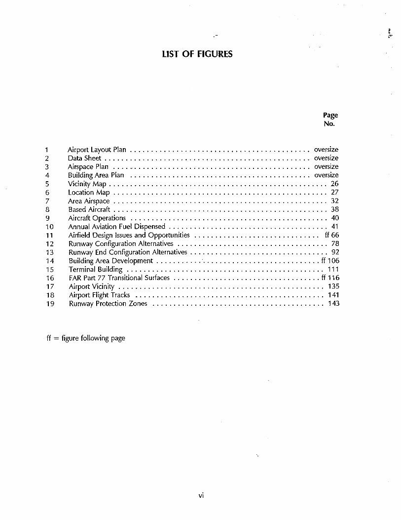
1 Airport Layout Plan . . . . . . . . . . . . . . . . . . . . . . . . . . . . . . . . . . . . . . . . . .. oversize2 Data Sheet . . . . . . . . . . . . . . . . . . . . . . . . . . . . . . . . . . . . . . . . . . . . . . . .. oversize3 Airspace Plan .....".......................................... oversize4 Building Area Plan ........................................... oversize5 Vicinity Map . . . . . . . . . . . . . . . . . . . . . . . . . . . . . . . . . . . . . . . . . . . . . . . . . . .. 266 Location Map . . . . . . . . . . . . . . . . . . . . . . . . . . . . . . . . . . . . . . . . . . . . . . . . . .. 277 Area Airspace . . . . . . . . . . . . . . . . . . . . . . . . . . . . . . . . . . . . . . . . . . . . . . . . . .. 328 Based Aircraft. . . . . . . . . . . . . . . . . . . . . . . . . . . . . . . . . . . . . . . . . . . . . . . . . .. 389 Aircraft Operations ............................................... 4010 Annual Aviation Fuel Dispensed . . . . . . . . . . . . . . . . . . . . . . . . . . . . . . . . . . . . .. 4111 Airfield Design Issues and Opportunities .............................. ff 66
12 Runway Configuration Alternatives . . . . . . . . . . . . . . . . . . . . . . . . . . . . . . . . . . .. 7813 Runway End Configuration Alternatives . . . . . . . . . . . . . . . . . . . . . . . . . . . . . . . .. 9214 Building Area Development . . . . . . . . . . .. . . . . . . . . . . . . . . . . . . . . . . . . . . . ff 10615 Terminal Building ............................................... 11116 FAR Part 77 Transitional Surfaces . . . . . . . . . . . . . . . . . . . . . . . . . . . . . . . . . . . ff 11617 Airport Vicinity . . . . . . . . . . . . . . . . . . . . . . . . . . . . . . . . . . . . . . . . . . . . . . . .. 13518 Airport Flight Tracks ............................................. 14119 Runway Protection Zones ......................................... 143
ff = figure following page
,
vi
.~
~
LIST OF TABLES
PageNo.
1 Proposed Airport Improvements . . . . . . . . . . . . . . . . . . . . . . . . . . . . . . . . . .. 162 Airport Profile" . . . . . . . . . . . . . . . . . . . . . . . . . . . . . . . . . . . . . . . . . . . . . . .. 243 Area Airports ................................................ 304 Summary of Aircraft Accidents .................................... 425 Master Plan Airport Activity Forecasts ......................."........ 51
6 Weighted Hourly Capacity. . . . . . . . . . . . . . . . . . . . . . . . . . . . . . . . . . . . . .. 557 Airfield Capacity Matrix . . . . . . . . . . . . . . . . . . . . . . . . . . . . . . . . . . . . . . . . . 618 Building Area and Airfield Capacity Relationships. , . . . . . . . , . . . . . . . . . . . .. 639 Airport Design Standards . . . . . , . . . . . . . . . . . . . . . . . . . . . . . . . . , . . . . . .. 6910 Runway Configuration Alternatives Analysis . . . . . . . . . . . . . . . . . . . . . . . . . .. 8211 Runway Longitudinal Alternatives Analysis . . . . . . . . . . . . . . . . . . . . . . . . . . . . 8612 Helicopter Operations Area Alternatives .........,.,................ 11813 Phase I Tower Establishment Ratio ................................ 12114 Aircraft Storage Capacities ...................................... 12815 Airport Development Staging Plan ................................ 13016 Land Uses in Runway Protection Zones ............................ 1441 7 Pro Forma Financial Projection . . . . . . . . . . . . . . . . . . . . . . . . . . . . . . . . . .. 15418 Maïketing Opportunity Analysis .................,............... ff 164
ff = figure following page
vii
~
Introduction
"'""
1
Introduction
STUDY BACKGROUND
Compton Airport is fairly typical of the nation's general aviation airport,in that it has seen little growth and, in some cases, a reduction in aero-nautical activity during the last decade. This activity trend is consistentwith the limited growth tendencies and aeronautical activity decreasesthat have characterized the nation's general aviation industry since thelate 1970's. As the general aviation industry rebounds in the 1990's,
particularly in the business and corporate aviation sector, Compton Air-port can expect to see a modest increase in aeronautical activity, both interms of aircraft operations and based aircraft.
In order to best determine its options and opportunities with respect tothe accommodation of such future aeronautical activity at Compton Air-port, the County of Los Angeles initiated this Airport Master Plan study.The County obtained a Federal Aviation Administration grant and en-gaged the firm of Hodges & Shutt to conduct the study.
The study was conducted in coordination with the staffs of the County ofLos Angeles-Department of Public Works-Aviation Division, the FederalAviation Administration, and the California Division of Aeronautics. Inaddition, key study findings and recommendations were reviewed withthe Los Angeles County Aviation Commission at public meetings heldthroughout the course of the study. Valuable input was also contributed
by the general public, airport users, and airport tenants.
CONTENTS OF THE PLAN
The Master Plan Report consists of nine chapters plus a set of appendices.
.,
A summary of the Master Plan's major conclusions and recommendationsis presented in the following chapter (Chapter 2). Chapter 2 also containsthe Airport Master Plan drawings.
1
Introduction / Chapter 1
Chapters 3 through 8 set forth the technical data and analyses involved inthe development of the Master Plan. The individual subject areas ad-dressed are: background and inventory; airport activity and capacityanalysis; airfield design; building area development; land use and envi-ronmental issues; and financial and implementation issues. Chapter 9presents an aviation marketing program that has been developed specifi-cally to assist the County in achieving its operational and financial goalsfor Compton Airport.
The appendices contain supporting information and supplemental docu-mentation.
2
~Summary
2
Summary
OVERVIEW
The Compton Airport Master Plan is a comprehensive assessment of thecurrent status and future course of development of the Airport. A majorobjective of the Master Plan is to formulate a concise, readily implement-able program to improve the overall operation, aircraft basing capacity,and financial status of the Airport. The Master Plan identifies the physicalimprovements and operational enhancements that are required to see theAirport through the 1990's and into the 21 st Century.
· Major Issues - The physical limitations and practical constraints ofthe airport site pose numerous design issues which have been a pri-mary focus of the Master Plan study. Among these issues are:
- Evaluate the advantages and disadvantages of the closely-spaced
parallel runway configuration.
- Provide adequate Runway Safety Areas and Object Free Areas inaccordance with FAA design standards.
- Upgrade airport facilities, service levels, and approach aids.
- Maximize beneficial use of available airport land area.
- Increase aircraft basing capacity consistent with available land area
and runway capacity.
- Provide for additional aircraft storage hangar development.
- Provide for safe, coordinated accommodation of both airplanes andhelicopters.
- Enhance overall airport and user security.
3
Summary I Chapter 2
Note To Reader
For the purposes of this report,the Airport Master Plan drawings
(4 sheets - Figures 1, 2, 3, and4) are presented in 24" x 32"
blueline folded format followingthe appendices.
4
- Evaluate off-airport land use impacts and identify potential mitiga-tion techniques.
· Plan Time Frame - The Master Plan covers a 20-year time frame.The emphasis, though, is on the first ten years of this period. Potentialactivity levels and facility needs during the later years are addressedprimarily to give an indication of the long-term direction of airportdevelopment.
· Future Revisions - The airport plan drawings should be reviewed as
necessary to assure that they continue to represent newly arising con-
ditions and facility needs. It is recommended that the plan drawingsbe updated periodically to reflect new construction. A thorough re-view and updating of the Airport Master Plan should be accomplishedwithin seven to ten years.
PLAN ORA WINGS
The existing configuration and recommended future development ofCompton Airport are graphically portrayed in three types of plan draw-ings:
· Airport Layout Plan - The Airport Layout Plan (ALP) is the most im-
portant of the airport plan drawings. An ALP adopted by the Countyof Los Angeles and approved by the Federal Aviation Administration isa prerequisite to FAA funding of airport improvement projects underthe Airport Improvement Program. The Compton Airport Layout Planand Airport Data Sheet are depicted in Figures 1 and 2 (oversize),respectively.
· Airspace Plan - The purpose of the Airspace Plan is to define andhelp protect the airspace essential to the safe operation of aircraft inthe vicinity of the Airport. The criteria which define the limits of thisairspace are established in Federal Aviation Regulation (FAR), Part 77,
"Objects Affecting Navigable Airspace." The Airspace Plan for Comp-ton Airport is shown in Figure 3 (oversize).
· Building Area Plan - The Building Area Plan shows details of the Air-port's core areas (terminal area, tiedown locations, hangar sites, auto-mobile parking, fixed base operations areas, etc.) not fully illustrated inthe Airport Layout Plan. Figure 4 (oversize) illustrates Compton Air-port's principal building area.
Summary I Chapter 2
BACKGROUND AND INVENTORY
· Location - Compton Airport lies entirely within the City of Comptonincorporated limits, approximately 10 miles south of the Los AngelesCity HalL.
· Historical Setting - Compton Airport was originally established in1924 and is the oldest continuously operating airport in the Los Angel-es basin. In 1966, Los Angeles County acquired the Airport for publicownership and use. During the ensuing years, the County expendedfederal, state, and county funds in the development and improvementof the Airport and its service capabilities.
· Management and Operations - The Airport is owned by Los AngelesCounty and is administered by the County's Department of PublicWorks-Aviation Division. Since April 1991, the day-to-day operationand management of the Airport has been provided by CO MARCO - aprivate management services firm working under contract to the Coun-
ty. COMARCO personnel provide all regular airport management,airport operations, maintenance services, and dispense all aviationfueL. The eight-member Los Angeles County Aviation Commissionserves to advise the County Board of Supervisors regarding the opera-tion and development of the County's five-airport system.
· Aeronautical Services - Four fixed base operators at Compton Airport
offer a basic range of general aviation services to the flying public.These services include aircraft rental, flight and ground instruction,aircraft maintenance and repair, aircraft sales, aircraft painting, and aircharter.
· Aeronautical Setting - Several large, complex metropolitan airport
are located in the vicinity of Compton Airport. As a result, theCompton area airspace is very complex and highly regulated. Aircraftoperating to/from Compton Airport must be equipped with appropriateavionics and must, in certin areas, be in radio contact with Air TrafficControl. Compton Airport is the only public-use airport in the LosAngeles basin that is not equipped with an airport traffic control tower.
AIRPORT ACTIVITY AND CAPACITY ANALYSIS
· Airport Role - It is anticipated that the past, present, and future role
of Compton Airport will remain essentially the same; that is, to servethe aeronautical needs of the personal, recreational, and small busi-ness aircraft user - both based and transient. Particularly noteworthyis the relatively high percentage (approximately 35%) of ComptonAirport-based aircraft that are considered "enthusiast' aircraft (e.g.,amateur-built, antiques, classic, sport, and warbird aircraft types).
5
.-.. ~.._~--~'-'_'i-__h__.-"_ ,__ ._~...
Summary I Chapter 2
Aircraft users desiring more sophisticated facilities (e.g., precision in-strument approaches; long, high-strength runways; corporate-orientedfixed base operators; etc.) can readily avail themselves of nearby alter-native airport such as Torrance Municipal, Long Beach, and Los An-
geles International airport.
Historical Airport Activity
· Based Aircraft - Compton Airport is similar to most of the nation'sprimarily general aviation airport in that it has experienced inconsis-tent, slow growth over the past 20 years. As of late 1990, an estimated
352 aircraft are based at the Airport. Approximately 22 of these air-craft are twin-engine fixed-wing airplanes and 4 are helicopters; theremainder of the based aircraft are single-engine fixed-wing airplanes.
· Aircraft Operations - An estimated 90,000 aircraft operations (take-offs and landings) took place at Compton Airport in 1990. It is esti-mated that over half of these operations were flight training-related(e.g., touch-and-go's).
Activity. Forecasts
· Based Aircraft - Despite the slowdown in nationwide general avia-
tion activity, the Master Plan concludes that there is potential for mod-est continued growth of Compton Airport's based aircraft population.The level of growth will in large part be dependent upon the aircraftbasing capacity of the Airport and the availability of aircraft storagehangars. The Master Plan projects a relatively modest growth rate forbased aircraft- an average of 1.75% per year - bringing the total to500 based aircraft in the year 2010. The large majority of these basedaircraft (over 90%) will be single-engine fixed-wing airplanes.
· Transient Aircraft - Airport improvements, together with County air-
port marketing effort, will contribute to increased demand for tran-sient aircraft parking at Compton Airport. Some 20 spaces (versus 12now designated) are projected to be needed to meet peak-perioddemand in 2010.
· Aircraft Operations - Aircraft operations are forecast to reach
156,000 annually in 20 years. Local flight training activity will con-tinue to comprise a substantial portion of these operations.
6
Summary I Chapter 2
Capacity Analysis
· Types of Capacity - The three forms of capacity typically consideredat general aviation airport are airfield, building area (or aircraft park-ing area), and environmental.
- The airfield capacity of Compton Airport's existing parallel runwaysystem ranges between 294,000 aircraft operations per year (in theAirport's existing configuration) to almost 400,000 operations peryear (assuming a "drift-off' taxiway and a managed shift to off-peakperiods).
- The airfield capacity associated with the future single runway con-figuration ranges between 193,000 aircraft operations per year(with existing peaking characteristics) to over 400,000 operationsper year (assuming optimum angled exit configuration and a man-aged shift to off-peak periods). In all cases, the capacity of thesingle runway configuration is more than adequate to accommo-date projected operational demand through the 20-year planningperiod.
- Given the physical constraints of the site, plus the need for land toaccommodate taxiways, fixed base operations, and terminal areafacilities in compliance with FAA design standards, the based andtransient aircraft parking capacity of the Airport is ultimately limitedto about 500 aircraft. Additional based aircraft could be accommo-dated if selected FAA design standards (e.g., aircraft parking limitand FAR Part 77 surfaces criteria) were relaxed and aircraft weremore closely parked. However, due to surface congestion andsafety considerations, such action is not recommended. The resul-tant building area capacity of the Airport is marginally sufficient toaccommodate the projected 20-year demand for based and tran-sient aircraft parking and aeronautical support facilities.
- The environmental capacity of an airport is generally related toaircraft noise impacts and the relative noise sensitivity of the airportenvirons. Due to the nature of aircraft operations at ComptonAirport, environmental capacity is not expected to be a significantconstraint on airport development. However, measures to mini-mize noise-related conflicts between the Airport and its surround-ings are, nonetheless, important.
· Capacity Relationships - The controlling capacity at Compton Airportis the limited availability of land for building area development. Thislimitation will ultimately constrain the number of aircraft that can bebased or parked on the Airport. Airfield and environmental capacitiesare not expected to constrain airport activity and growth.
7
Summary / Chapter 2
Typical aircraft encompassedwithin Airport Reference CodeB-1 (Small Airplanes) include:
. Cessna 172 Skyhawk
. Rockwell 690A
. Beechcraft Bonanza
. Cessna Citation I
8
AIRFIELD DESIGN
The airfield portion of Compton Airport is comprised of the runway/parallel taxiway system, the runway protection zones, and the requiredsafety areas. In addition, those facilities and equipment generally associ-ated with the airfield area (e.g., visual glide slope indicators, wind cones,etc.) are included as airfield design elements. The assessment of airfielddesign issues and alternatives, and the development of the recommendedairfield configuration, were key factors considered in the formulation ofthe Master Plan for Compton Airport.
Airfield Design Factors
· Airport Reference Code - The Master Plan analysis of airport roleand aviation activity indicates that Compton Airport will continue toserve as a public-use airport capable of accommodating based andtransient single-engine and light twin-engine general aviation aircraft.Accordingly, for design purposes Compton Airport is classified for thepresent and foreseeable future in the Airport Reference Code B-1
(Small AirplanesNisual Approach) category. This airport design catego-
ry provides for the use and accommodation of virtually all single-en-gine and light twin-engine general aviation aircraft currently using theAirport or anticipated to use the Airport throughout the planning fu-ture.
· Critical Aircraft - The critical aircraft anticipated to use Compton Air-port within the 20-year planning period are encompassed within Air-craft Approach Categories A and B, and Airplane Design Group I(Small AirplanesNisual Approach). Such critical aircraft are defined ashaving a maximum certificated take-off weight of 12,500 pounds orless, a wingspan of less than 49 feet, and an approach speed of lessthan 121 knots.
· Instrument Approach Potential - Due to airspace complexity and
airfield design considerations, it may be difficult to establish a viableinstrument approach procedure, either precision or non precision, thatfully meets FAA siting requirements and adequately serves the Airport.However, the option of establishing a nonprecision instrument ap-proach procedure (e.g., NDB, VOR, LOC, LDA, SDF, LORAN-C, etc,)at Compton Airport should be preserved. A formal FAA aeronautical
study will be required to determine the appropriate type of instrumentapproach and the approach/landing minimums. For airport masterplanning and design purposes, a "visual" (i.e., circling approach) classi-fication has been assumed.
· Specific Airfeld Design Issues and Concerns - The following site-specific issues and concerns were addressed as part of the MasterPlan:
Summary I Chapter 2
- Continue to emphasize the accommodation and seivicing of gener-al aviation aircraft - both personal/recreational aircraft users andbusiness/corporate aircraft users.
- Maintain runway length consistent with ARC B-1 (Small Airplanes)standards.
- Provide appropriate on-airport Object Free Areas and RunwaySafety Areas.
- Properly identify and depict Runway Protection Zones (formerly
Clear Zones).
- Provide for coordinated accommodation of both airplanes andhelicopters.
- Provide enhanced visual and instrument approach aids.
- Maximize available area for development of aircraft storage hangarsand tiedowns.
- Evaluate feasibility of acquiring additional land area.
Proposed Airfield Improvements
· Major Features - A variety of airfield design alternatives were consid-ered as part of the Master Pian study. The recommended plan forairfield development is depicted in Figures 1 and 2. The major fea-tures of the airfield design illustrated on the Airport Layout Plan in-clude:
- For the short- to mid-term, maintain "As_Is" parallel runways config-
uration and maximize existing aircraft basing capacity within avail-able area.
- Provide for appropriately sized Runway Safety Areas and ObjectFree Areas off each runway end. This action results in a publishedrunway length of 3,670 feet.
- Utilize entrance taxiway at each runway end to maximize utility .and safety of the Airport.
- Maintain existing physical locations of displaced thresholds at eachrunway end.
- Improve Runway 7L-25R through installation of Medium-IntensityRunway Lights, Visual Glide Slope Indicators, and Runway EndIdentifier Lights.
'.
9
Summary I Chapter 2
- When warranted by based aircraft demand, close Runway 7R-25Land adjust airport operation consistent with a single runway config-uration.
- Establish new north and south side parallel taxiways with 150-footseparation from runway centerline. Provide holding bay/run-uppad at approach end of runway.
- Expand aircraft basing capacity in compliance with FAA design/operational standards.
· Cost - The preliminary cost estimate for the airfield improvementsidentified in this Master Plan is $6.3 million. Of this amount, $2.6million is eligible for federal funding under the Airport ImprovementPlan.
· Engineering Design - The above improvements represent a planningconcept that is based upon Master Plan analysis and preliminary com-putations. It is anticipated that the final engineering design will utilizethese planning concepts as a guide and generate refined design detailsand cost estimates.
· Construction - Implementation of the proposed airfield design willentail substantial reconstruction of the runway surface. Project con-struction will necessitate the closure of Runway 7L-25R for a period ofapproximately four to six weeks. During this time, Runway 7R-25Lwould remain open and fully operationaL.
BUILDING AREA DEVELOPMENT
The building area of an airport encompasses all of the airport propertnot required for airfield purposes (i.e., runway/taxiway system). At Comp-ton Airport, the building area is located on both the north and south sidesof the airfield. The primary public areas (e,g., terminal complex, fixedbase operations, etc.) are located on the south side of the airfield.
Design Considerations
· Compliance with FAA Airport Design Standards - All building areastructures, fixed objects, and aircraft parking areas should be locatedso as to comply with FAA design standards. Many elements of Comp-ton Airport's existing layout and design do not comply with currentFAA design/operational standards. At Compton Airport, the appropri-ate present and future FAA design category is Airport Reference CodeB-1 (Small AirplanesNisual Approach).
10
Summary I Chapter 2
· Maximize Development and Use of Building Area - Analysis indi-cates that the cost of acquiring additional land to support ComptonAirport operations is prohibitive at this time. The Airport is nearing itscurrent aircraft basing capacity. To accommodate additional basedaircraft, the space-inefficient, closely-spaced parallel runways could bereplaced by a single runway configuration.
· Accommodation of Increased Helicopter Activity - The Airport isexperiencing growth in based municipal services helicopter operations.It is an objective of the Master Plan to provide for the safe and coordi-nated use of the Airport by both airplanes and helicopters.
· Enhancement of Airport Safety and Security - At Compton Airport,the somewhat constrained land area available and congested urbanenvironment require that appropriate attention be devoted to ensuringthe continued safety and security of airport operations.
· Terminal Area Development - The County's recently constructedterminal building provides a beneficial focal point for public use of theAirport. The south side of the Airport now offers the public and tran-sient aircraft user a comprehensive range of general aviation services.
· Development Staging - The staging of improvements to the buildingarea must be well-timed and coordinated. The objective is to have aplan that is flexible enough to adapt to changes in type and pace offacility demands, is cost-effective, and also makes sense at each stageof development. At Compton Airport, all building area facilities andimprovements must be compatible with both the present and futurerunway configurations.
Facility Requirements
· Ainield Configuration - During the mid-range time frame (5-10
years), is recommended that the Airport's existing closely-spaced paral-lel runways system be replaced by a single runway based on theRunway 7L-25R alignment. This reconfiguration of the airfield willpermit increased building area capacity in compliance with FAA designstandards.
· Aircraft Storage and Parking - Demand for Compton Airport based
aircraft hangar and tiedown .facilities is projected to increase by anestimated 42% over the 20-year planning period, with the majority ofthis demand being for individual aircraft storage hangars. Sufficientarea is available on the Airport to accommodate up to 130 new han-gar units, provided that the parallel runway system is converted to thesingle runway configuration.
· Terminal Area - Early in the Compton Airport master planning pro-
cess, the County identified a site for the new terminal/administration
11
Summary I Chapter 2
building. The terminal/administration building was subsequently con-structed in mid-1991. The selected location of the terminal building isconsidered optimum and is consistent with the overall existing andfuture configurations of the Airport. An adequate area for the parkingof airport usef automobiles is provided in front of the terminal build-ing.
· Aircraft Fueling Facilities - An importnt consideration in the design
and use of the new terminal area is the appropriate location and typeof aircraft fueling facilities. Based upon the assessment of the Airport'srole and aviation activity forecasts, it is recommended that the Air-port's aircraft fueling facilities be initially oriented to service piston-powered aircraft with at least two grades of aviation gasoline. Ideally,these two grades of aviation gasoline would be 80 octane and 100octane. As an alternative to 100, the Airport could offer 100LL octaneaviation gasoline.
Also worthy of consideration is the potential for the Airport to storeand dispense let-A fuel to the City of Compton Police Department tur-bine-powered helicopters based at Compton Airport. The let-A fuelwould be most efficiently dispensed to the CPO helicopters and theoccasional civilian or military turbine-powered aircraft through the useof refueler trucks.
In keeping with the County's established operational format at Comp-ton and its other system airport, the "fuel island" configuration isretained. The future fuel island, with associated fuel-dispensingequipment and underground storage tanks, would be located approxi-mately 50 feet northeast of the present island's location. This newlocation will provide more room for aircraft maneuvering in the fuelingarea.
· Other Building Area Facilities - The following facilities are identifiedas integral elements of the building area plan:
- Airport Traffc Control Tower - Potential future site in the southcentral area of the Airport.
- Owner-Performed Aircraft Maintenance Facility - Located adjacentto the aircraft washing facility in the northeast corner of the Airport.Alternatively, a facility could also be located in the Airport's north-west corner.
- Airfield Maintenance Facility - Located in the southeast corner of
the Airport, as at present.
12
Summary / Chapter 2
LAND USE AND ENVIRONMENTAL ISSUES
Compton Airport is located in the midst of an extensively developedurban area. This off-airport urban development is composed primarily ofsingle- and multi-family residences, and commercial/industrial uses.Despite the potential for incompatibility and conflict between the Airportand certin of these off-airport land uses, the Airport and surroundingcommunity have existed over the years in relative harmony.
Current and Projected land Use impact and CompatibiltyConcerns
· Noise - A limited analysis of noise contours was last performed for
Compton Airport in 1972. Due to changes in aircraft operation levelsand flight tracks over the ensuing years, it is strongly recommendedthat these contours be updated as an integral element of any futureLos Angeles County Airport Land Use Plan. As noted above, aircraftnoise is not currently a significant issue at the Airport, but neverthe-less, its impact should be assessed and mitigative actions implemented.
· Safety - The most critical areas with regard to flight hazards are with-in the approaches to the Airport's runway. At Compton Airport, theextensive development of the land areas underlying the Airport's ap-proaches has resulted in numerous buildings, antennas, pole lines, andtrees that have the potential to be considered as obstructions andhazards to flight. The Master Plan recommends that action should betaken by the County and the City of Compton to ensure that no fur-ther obstructions or hazards to flight are permitted within the areasdefined by FAR Part 77.
· Overflight - Compton Airport's overflight impacts are generally con-centrated under the airport traffic pattern. Due to the nonstandardtraffic pattern used for Runways 7L and 25R, the majority of aircraftoverflights occur to the south side of the Airport. The resultant down-wind leg of the traffic pattern overlies the commercial/industrial areabordering the north side of Highway 91. Historically, the Airport hasreceived very few aircraft-related noise complaints from area residents.The few complaints which are received are usually associated with adistinct, atypical aircraft noise event as opposed to normal aircraftoverflight operations.
Land Use Controls and Impact Mitigation Techniques
· Airport Land Use Plan - The California State Legislature is currentlyreconsidering its requirement that the Los Angeles Regional PlanningCommission prepare a comprehensive land use plan for each public-use airport in Los Angeles County. Irrespective of the State's ultimate
13
Summary / Chapter 2
finding, it is strongly recommended that the County prepare a compre-hensive land use plan for Compton Airport. This plan should identifyspecific land use impacts and compatibility concerns, and promulgateland use controls and impact mitigation actions. It is recommendedthat the comprehensive land use plan incorporate the land use com-patibility measures identified in this Master Plan.
· Land Acquisition - Due to the intensive urban development which
has taken place within the Airport's Runway Protection Zones, pur-chase and/or conversion of these incompatible uses would be bothimpractical and very expensive. However, the County and City shouldendeavor to reverse or mitigate this existing land use incompatibility atevery reasonable opportunity.
· Height Limitation - Numerous obstructions currently penetrate theFAR Part 77 approach surfaces for the Airport. Unless there is effec-tive land use regulation and control, construction of new structuresand obstructions could require further restrictions on airport opera-tions. The prevention of further encroachments and incompatibleland uses should be the highest priority of both Los Angeles Countyand the City of Compton.
It is recommended that the County and the City establish height limi-tations for the Airport environs that are primarily based upon the re-quirements of FAR Part 77. For the Airport's Runway ProtectionZones, it is suggested that the height limitations be based, at a mini-mum, upon the existing clearance plane for each runway's displacedthreshold.
FINANCIAL AND IMPLEMENTATION ISSUES
The financial element of the Airport Master Plan addresses the timing ofthe proposed airport improvement projects, the estimated costs of theseimprovements, and the anticipated future airport revenues and expenses.
Capital Improvement Program
· Project Staging - Generally, it is preferable to spread out the imple-mentation of facility improvements to match forecast increases inairport activity. Compton Airport, however, is approaching the pointwhere additional aircraft- basing demand can only be accommodatedby converting the existing parallel runway system to the single runwayconfiguration. This reconfiguration will necessitate that a substantialexpenditure of airport improvement funds be made in the mid-rangetime frame. Table 1 lists the airport improvements proposed in the
1 II'""
Summary / Chapter 2
Master Plan and indicates the time period within which it is recom-mended they be implemented.
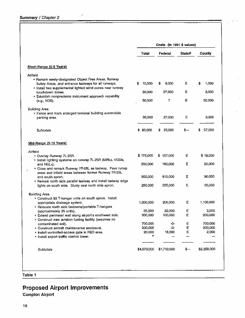
· Short-Range Project - There are no major projects slated for con-struction in the short-range (within five years). However, a number ofprojects to enhance the safety and operation of the Airport are pro-posed:
- Remark newly designated Object Free Areas, Runway Safety Areas,and entrance taxiways for all runways.
- Install two supplemental lighted wind cones near runway touch-down zones.
- Establish non precision instrument approach capability (e.g., NDB).
- Fence and mark terminal area auto parking lot.
The bulk of the proposed improvements are programmed for the mid-range (5-10) years.
· Costs - The total estimated cost of the improvement projects identi-fied in the Master Plan is approximately $6.3 million. Of this amount,a significant proportion ($4.1 million) is proposed for mid-range imple-mentation.
· Funding Sources - It is proposed that the recommended airport im-provements be funded through a combination of Federal AviationAdministration, California Division of Aeronautics, Los Angeles County,and private sources.
- The FAA Airport Improvement Program is the largest single sourceof proposed funding. Nearly $2.6 million of the total improve-ments are eligible for FAA grants. Some $1.7 million of thisamount is for mid-range projects, particularly the runway reconfigu-ration and parallel taxiway construction.
- The anticipated Los Angeles County share of the improvement
costs over the 20-year Master Plan period is approximately $3.7million. The major improvement requiring County funding is thereplacement of the aircraft fuel storage and dispensing system. Inaddition, it is anticipated that the County will fund the constructionof all new aircraft storage hangars - approximately 106 hangarunits. Neither of these projects is eligible for FAA or state grants.
However, both of these projects are eligible for a loan under theState's airport improvement loan program.
15
Summary I Chapter 2
Costs (In 1991 $ values)
Total Federal State# County
Short-Range (0-5 Years)
Airfield. Remark newly-designated Object Free Areas, Runway
Safety Areas, and entrance taxiways for all runways. $ 10,000 $ 9,00 E $ 1,00. Install two supplemental lighted wind cones near runway
touchdown zones, 30,00 27,00 E 3,00. Establish non precision instrument approach capabilty
(e.g., NDB), 50,00 ? E 50,00
Building Area. Fence and mark enlarged terminal building automobile
parking area. 30,00 27,00 E 3,00
Subtotals $ 80,00 $ 23,00 $--- $ 57,000
Mid-Range (5-10 Years)
Airiieid. Overlay Runway 7L-25R. $ 175,00 $ 157,000 E $ 18,00. Install lighting systems on runway 7L-25R (MIRLs, VGSls,
and REILs). 200,00 180,00 E 20,00. Close and remark Runway 7R-25L as taxiway. Pave runup
areas and infield areas between former Runway 7R-25Land south apron, 90,00 810,00 E 90,00
. Remark north side parallel taxiway and install taxiway edgelights on south side. Slurry seal north side apron, 250,00 225,00 E 25,000
Building Area. Construct 53 T-hangar units on south apron. Install
appropriate drainage system. 1,300,00 20,00 E 1,100,00. Relocate north side tiedowns/portable T-hangars
(approximately 35 units), 25,00 22,00 E 3,000. Exend perimeter wall along airport's southwest side, 300,00 100,00 E 200,00. Construct new aviation fueling facilit (assumes no
contaminated soil), 700,00 .(- E 700,000. Construct aircraft maintenance enclosure, 200,00 .(- E 200,00. Install controlled-access gate in FBO area. 20,00 18,00 E 2,00. Install airport traffic control tower, "*
Subtotals $4,070,00 $1,712,00 $--- $2,358,00
Table 1
Proposed Airport ImprovementsCompton Airport
16
Summary I Chapter 2
Costs (in 1991 $ values)
Total Federal State# County
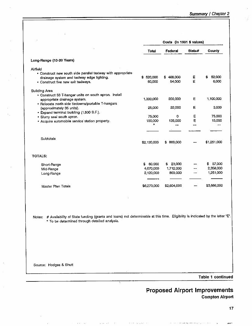
Long-Range (10-20 Years)
Airfield. Construct new south side parallel taxiway with appropriate
drainage system and taxiway edge lighting. $ 520,00 $ 46,00 E $ 52,00. Construct five new exit taxiways, 60,00 54,00 E 6,00
Building Area. Construct 53 T-hangar units on south apron, Install
appropriate drainage system, 1,300,00 200,00 E 1,100,00. Relocate north side tiedowns/portable T-hangars
(approximately 35 units). 25,00 22,00 E 3,00. Expand terminal building (1,500 S.F).. Slurry seal south apron, 75,00 0 E 75,00. Acquire automobile service" station propert, 150,00 135,00 E 15,00
*
Subtotals$2,120,00 $ 869,00 $1,251,00
TOTALS:
Short-Range $ 80,00 $ 23,00 $ 57,00Mid-Range 4,070,00 1,712,00 2,35,00Long-Range 2,120,00 869,00 1,251,00
Master Plan Totals $6,270,00 $2,60,00 $3,66,00
Notes: # Availabilit of State funding (grants and loans) not determinable at this time. Eligibilty is indicated by the letter "E".* To be determined through detailed analysis.
Source: Hodges & Shutt
Table 1 continued
Proposed Airport ImprovementsCompton Airport
17
Summary I Chapter 2
Financial Projection
· Summary - Within recent years, Compton Airport's operating reve-nues have exceeded its operating expenses by a modest margin. This
has not always been the case in the past. This positive income trendis projected to continue throughout the five-year financial planningperiod and into the future. These airport funds - both income andretained earnings - will prove most useful in funding the County's
share of the proposed improvement program. It should be recogniz-ed, however, that the Compton Airport improvement program fundingand cash flow requirements may, from time to time, necessitate theuse of County airport system funds on an interim or supplementalbasis. Through the use of such an in-house, self-financing approach,the improvement of the Airport can proceed in a timely and cost-effective manner.
· Financial Recommendations - The County should continue to ag-gressively develop all revenue resources and strictly control and mini-mize all operating expenses.
- Airport rates and charges should be reviewed and adjusted on aregular basis to ensure that maximum reasonable revenue is gener-ated consistent with the Airport's role, facilities, and user demand.
- Additional private and commercial aviation development on theAirport should be encouraged to bolster airport revenues and ser-vice offerings.
- The ability of the Airport to accommodate based and transientaircraft within its designated service role should be maximized.
Master Plan Adoption
· Environmental Impact Documentation - An Initial Study, preparedin accordance with California Environmental Quality Act (CEQA)guidelines, was performed as an integral part of this Master Plan. TheInitial Study should be sufficient to enable preparation of a NegativeDeclaration allowing adoption of the Airport Master Plan.
· Plan Review - The County Aviation Commission, the Airport LandUse Commission, and the County Planning Commission each havecertin review responsibilities with regard to the Airport Master Plan:
- The Aviation Commission reviews the overall plan and makes rec-ommendatiòns regarding its adoption to the Board of Supervisors.
18
Summary / Chapter 2
- The Airport Land Use Commission (the Los Angeles Regional Plan-ning Commission) is required by state law to review the MasterPlan prior to its adoption (PENDING).
- The County Planning Commission has responsibility for: (1) deter-mining the consistency between the Airport Master Plan and theCounty General Plan; and (2) certifying the Negative Declaration.
· Board of Supervisors - The County Board of Supervisors has theultimate responsibility for adoption of the Airport Master Plan.
· Federal Aviation Administration - Following adoption of the Master
Plan, the FAA will formally review and approve the Airport LayoutPlan drawings as the basis for future engineering design and granteligibility of specific projects,
Implementation
· Project Funding - Once the plan has been adopted and a decision
has been made to proceed with implementation, the County shouldsoon thereafter submit an Airport Improvement Program grant preap-plication to the California Division of Aeronautics and the FederalAviation Administration.
· Engineering Design - The County will need to arrange a contractualagreement with a qualified airport engineer to prepare the engineeringdesigns for the proposed improvements. To assure continuity in de-sign development, it is suggested that the agreement cover not just theimmediate projects, but other major improvements proposed to beconstructed over the next three to five years.
· Environmental Impact Documentation - To satisfy CEQA require-ments, an environmental analysis may need to be performed withregard to the proposed runway reconfiguration and increase in aircraftparking capacity. There are no apparent requirements for preparationof a federal environmental document.
AVIATION MARKETING PROGRAM
As an integral element of this Master Plan, a suggested program wasdeveloped to market the facilities, capabilities, and services of ComptonAirport to both the general aviation community and the community-at-large. The purpose of this program is to improve the Airport's overalloperating environment and financial position, encourage the developmentand growth of desired on-airport aviation businesses and concessions, andenhance user and public perceptions of the Airport and general aviation.
19
Summary / Chapter 2
Airport Role and User Characteristics
The Airport's primary role has historically been and will continue to be asa base of operations and destination for personal and recreational aircraftusers. A high percentage of these personal and recreational aircraft areconsidered "enthusiast' aircraft (e.g., antique, experimental, and warbirdaircraft types). In addition, greater use of the Airport can be expected inthe future by the type of sophisticated, high-performance, single-engineairplanes most commonly operated by small businesses.
Aviation Marketing Opportunity Analysis
Considerable capital arid operating expenditures would be required atCompton Airport to attract and accommodate high-performance, multi-engine turbine-powered bu'siness/corporate aircraft on a regular basis.Accordingly, it is concluded that the primary market groups for ComptonAirport are the personal and recreational aircraft user and small businessaircraft user.
Aviation Marketing Plan
To fully realize the County's operational and financial goals for ComptonAirport, it is suggested that the following marketing-related actions betaken:
· Endeavor to satisfy the Airport's existing based and transient aircraftuser groups.
· Attract additional based and transient aircraft users consistent with theAirport's stated operational role as a facility predominantly serving thepersonal/recreational aircraft user and small business aircraft usergroups.
· Provide a positive airport environment that encourages the develop-ment and growth of desired on-airport aviation businesses and conces-sions.
· Promote the unique attributes and advantages of the Airport to therespective aircraft user groups, local businesses, and the community-at-large.
The Aviation Marketing Program as detailed in the Master Plan identifiesa comprehensive listing of aviation marketing actions prepared specificallyfor application at Compton Airport. The listing differentiates betweenmarketing actions related to based aircraft users, airport tenants and con-cessionaires, and the community-at-Iarge, and offers specific suggestions
20

Summary I Chapter 2
as to how the Airport can be most effectively marketed to its primary usergroups and the general public.
The Aviation Marketing Program for Compton Airport as presented hereincomplements the Airport Master Plan in that for the Airport to achieve itsprojected aviation activity levels, a concerted marketing and facility im-provement program wil be reqUired.
21

22
~Background
andInventory
- -'- :'-"-'~--'-",-,-.",....,.,.~,~ -:'~"'-'--,'
3
Background and Inventory
COMPTON AIRPORT
A brief profile of Compton Airport's major features, air traffic environ-ment, management/operational format, aeronautical services, and commu-nity setting is presented in Table 2. The accompanying paragraphs high-light a number of key points.
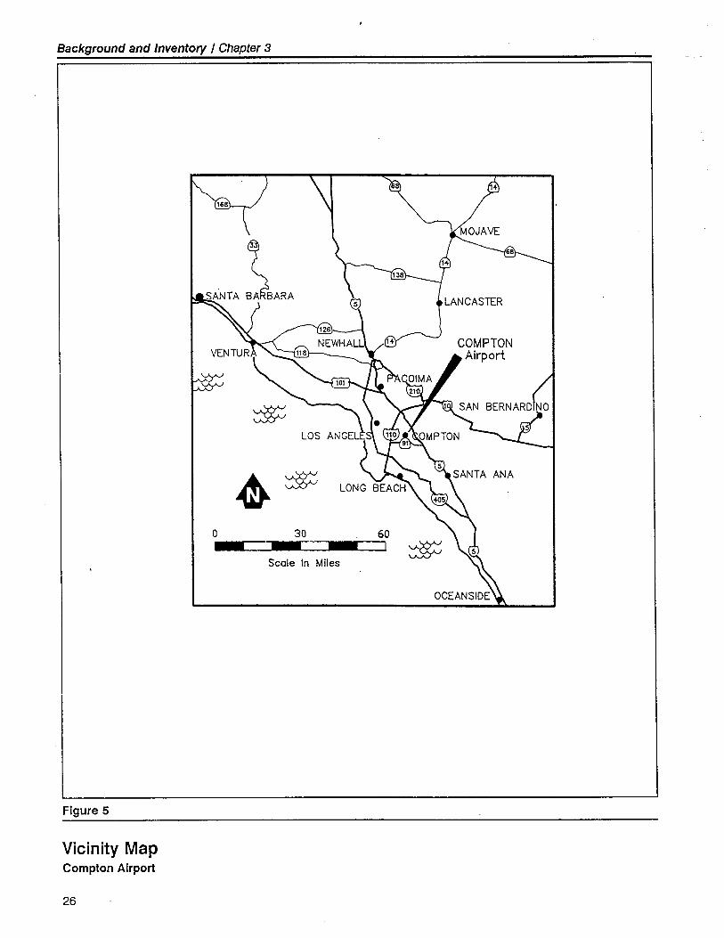
Location and Environs
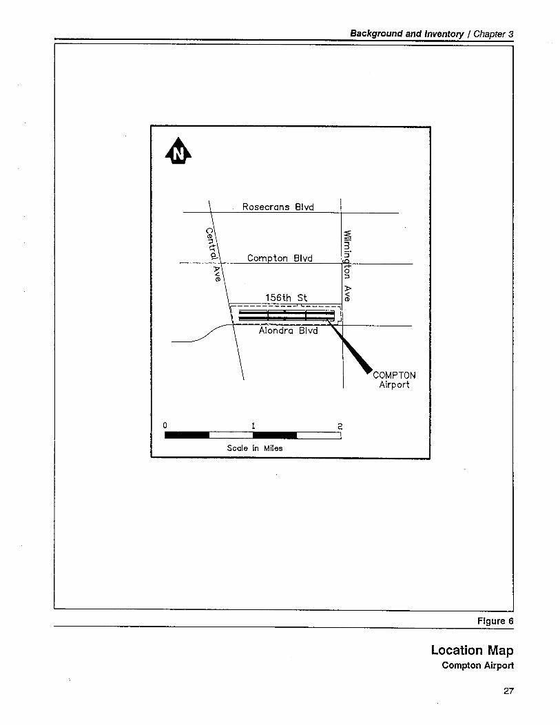
Compton Airport is located in the central portion of the Los Angelesbasin, approximately ten miles south of the Los Angeles City Hall (Figure5). The Airport lies entirely within the City of Compton incorporatedlimits at an elevation of 97 feet above Mean Sea LeveL. Alondra Boule-vard is the primary roadway serving the Airport (see Figure 6).
Most of the land surrounding the Airport consists of heavily urbanizeddevelopment - both residential and commercial/industrial uses. Signifi-cant industrial development is occurring one mile south of ComptonAirport along Highway 91 - a major east-west freeway.
The Airport is also well located with respect to Interstate Highways 110and 710, as well as Interstate 105, presently under construction. A pas-senger station for the newly developed Los Angeles area light rail system- the "Blue Line" - is located approximately 1.5 miles' walking distance
east of the Airport. There is no public transit service currently connecting
the Airport with the Blue Line.
Airport Development
Compton Airport is the oldest continuoùsly operating airport in the LosAngeles basin. Initial development of Compton Airport occurred in 1924.During Compton Airport's early years, the Airport was privately-owned
23
Background and Inventory / Chapter 3
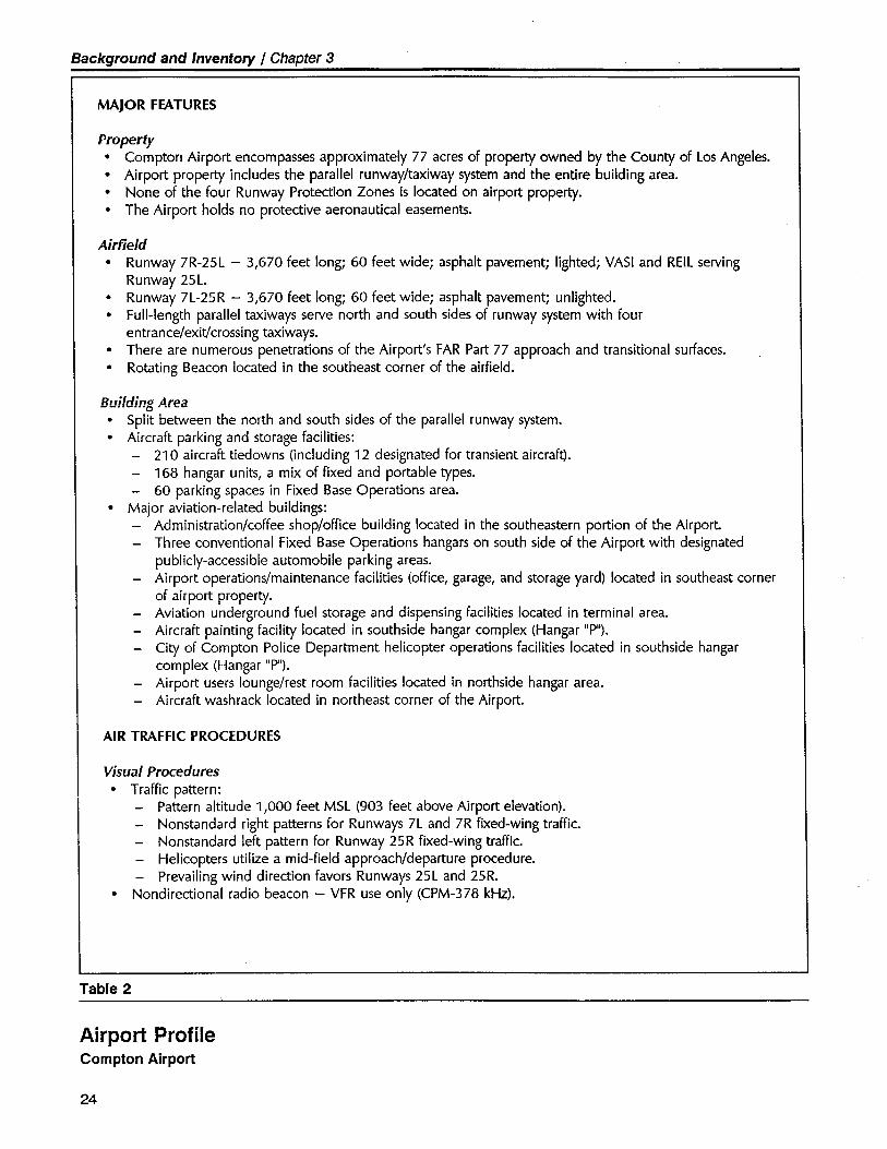
MAJOR FEATURES
Property· Compton Airport encompasses approximately 77 acres of propert owned by the County of Los Angeles.· Airport propert includes the parallel runway/taxiway system and the entire building area.
· None of the four Runway Protection Zones is located on airport propert.· The Airport holds no protective aeronautical easements.
Airfield· Runway 7R-25L - 3,670 feet long; 60 feet wide; asphalt pavement; lighted; VAS I and REIL serving
Runway 25L.· Runway 7L-25R - 3,670 feet long; 60 feet wide; asphalt pavement; unlighted.· Full-length parallel taxiways serve north and south sides of runway system with four
entrance/exit/crossing taxiways.
· There are numerous penetrations of the Airport's FAR Part 77 approach and transitional surfaces.· Rotating Beacon located in the southeast corner of the airfield.
Building Area· Split between the north and south sides of the parallel runway system.· Aircraft parking and storage facilities:
- 210 aircraft tiedowns (including 12 designated for transient aircraft).- 168 hangar units, a mix of fixed and portable types.- 60 parking spaces in Fixed Base Operations area.
· Major aviation-related buildings:- Administration/coffee shop/office building located in the southeastern portion of the Airport
- Three conventional Fixed Base Operations hangars on south side of the Airport with designatedpublicly-accessible automobile parking areas.
- Airport operations/maintenance facilities (office, garage, and storage yard) located in southeast cornerof airport property.
- Aviation underground fuel storage and dispensing facilities located in terminal area.- Aircraft painting facility located in southside hangar complex (Hangar IOPIO).
- City of Compton Police Department helicopter operations facilities located in southside hangarcomplex (Hangar IOPIO).
- Airport users lounge/rest room facilities located in northside hangar area.- Aircraft wash rack located in northeast corner of the Airport.
AIR TRAFFIC PROCEDURES
Visual Procedures· Traffic pattern:
- Pattern altitude 1,000 feet MSL (903 feet above Airport elevation).
- Nonstandard right patterns for Runways 7L and 7R fixed-wing traffic.- Nonstandard left pattern for Runway 25R fixed-wing traffic.- Helicopters utilize a mid-field approach/departure procedure.
- Prevailing wind direction favors Runways 25L and 25R.
· Nondirectional radio beacon - VFR use only (CPM-378 kHz).
Table 2
Airport ProfileCompton Airport
24
Background and Inventory / Chapter 3
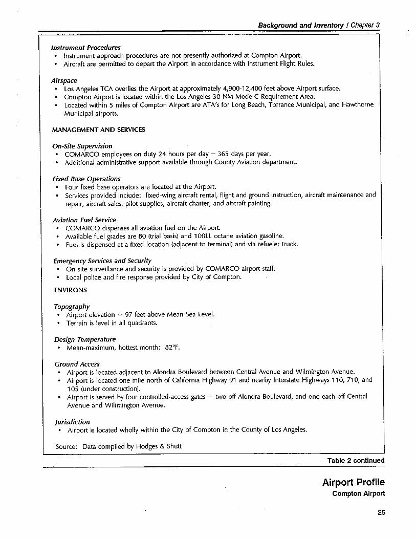
Insuument Procedures· Instrument approach procedures are not presently authorized at Compton Airport
· Aircraft are permitted to depart the Airport in accordance with Instrument Flight Rules.
Airspace· Los Angeles TCA overlies the Airport at approximately 4,900-12,400 feet above Airport surface.· Compton Airport is located within the Los Angeles 30 NM Mode C Requirement Area.· Located within 5 miles of Compton Airport are ATA's for Long Beach, Torrance Municipal, and Hawthorne
Municipal airports.
MANAGEMENT AND SERVICES
On-Site Supervision· COMARCO employees on duty 24 hours per day - 365 days per year.. Additional administrative support available through County Aviation department
Fixed Base Operations· Four fixed base operators are located at the Airport.. Services provided include: fixed-wing aircraft rental, flight and ground instruction, aircraft maintenance and
repair, aircraft sales, pilot supplies, aircraft charter, and aircraft painting.
Aviation Fuel Service
· COMARCO dispenses all aviation fuel on the Airport.· Available fuel grades are 80 (trial basis) and 100LL octane aviation gasoline.
· Fuel is dispensed at a fixed location (adjacent to terminal) and via refueler truck.
Emergency Services and Seurity
· On-site surveillance and security is provided by COMARCO airport staff.· Local police and fire response provided by City of Compton.
ENVIRONS
Topography· Airport elevation - 97 feet above Mean Sea LeveL.
· Terrain is level in all quadrants.
Design Temperature· Mean-maximum, hottest month: 82°F.
Ground Access· Airport is located adjacent to Alondra Boulevard between Central Avenue and Wilmington Avenue.· Airport is located one mile north of California Highway 91 and nearby Interstate Highways 110, 710, and
105 (under construction).· Airport is served by four controlled-access gates - two off Alondra Boulevard, and one each off Central
Avenue and Wilimington Avenue.
Jurisdiction· Airport is located wholly within the City of Compton in the County of Los Angeles.
Source: Data compiled by Hodges & Shutt
Table 2 continued
Airport ProfileCompton Airport
25
Background and Inventory / Chapter 3
~ $0 30 60
I ~Scale In Miles
~
Figure 5
Vicinity MapCompton Airport
26
Background and Inventory / Chapter 3
.
o
Rosecrans Blvd
~3:;'r+0::~
156th St -:(\
r ìi
Alondra Blvd
1
Scale In Miles
COMPTONAirport
Figure 6
2I
Location MapCompton Airport
27
Background and Inventory / Chapter 3
and operated as a public-use facility. The Airport's first paved runwaywas oriented in a east-west direction and served primarily as a takeoffsurface for small single-engine airplanes. The single paved runway wassupplemented by two parallel turf runways, also oriented in an east-westdirection.
In 1964, Valiant I nvestment purchased the Airport from its private ownersand leased the facility to Los Angeles County for public operation anduse. The County subsequently acquired the Airport in 1966 and expend-ed federal, state, and County funds to further develop and improve theairport facilities and service capabilities. Additional detail regarding thechronology of Compton Airport development is presented in Appendix A.
The present Compton Airport occupies a 77-acre, rectangular site locatedadjacent to the north side of Alondra Boulevard between Central Avenueand Wilmington Avenue. The Airport is situated on level ground with nosignificant terrain features. The two parallel, 3,670-foot by 60-foot pavedrunways are oriented in a roughly east-west direction (0700 - 2500 mag-netic) and are served by full-length parallel taxiways on the outer sides.Due to obstructions and safety considerations, a displaced threshold islocated at each runway end. Building area development is situated onboth the north and south sides of the airfield. All public terminal areafacilities, fixed base operations hangars, and County airfield operations/maintenance facilities are located on the Airport's south side. In 1990,approximately 350 aircraft were based at the Airport and generated anestimated 90,000 takeoffs and landings.
An inventory of existing airport facilities is presented in Appendix B.
Management and Operations
Compton Airport is owned by Los Angeles County. Administration of theAirport is the responsibility of the County's Department of Public Works- Aviation Division. Compton Airport is one of five general aviationairport owned by the County.
Since April 1991, the day-to-day management, operation, and develop-ment of the Airport have been provided by COMARCO - a private man-agement services firm working under contract to the County. COMARCOoperates all five County-owned airport under the terms of a 20-yearoperating agreement. Under these arrangements, the County retainsadministrative oversight responsibilities and COMARCO is responsible forthe operation, maintenance, and development of the facilities.
An airport manager and supporting staff of seven COMARCO employeesare normally stationed at the Airport. The on-site COMARCO airportpersonnel are further supported by COMARCO administrative and techni-cal staff based throughout the County airport system. CO MARCO airportpersonnel stationed at the Airport are responsible for airport management,
28
Background and Inventory / Chapter 3
operations, and maintenance. In addition, COMARCO personnel dis-pense aviation fuel at the Airport. COMARCO personnel are present atthe Airport on a 24-hour-per-day, 365-days-per-year basis.
The eight-member Los Angeles County Aviation Commission meetsmonthly to work with County staff and to advise the County Board ofSupervisors regarding the operation and development of the County'sairport system. All final policy decisions are the responsibility of theCounty Board of Supervisors.
Aeronauiicai Services
The Airport's four fixed base operators and specialty operators offer basicgeneral aviation services including aircraft rental, flight and ground in-struction, aircraft maintenance and repair, aircraft sales, pilot supplies,aircraft charter, and aircraft painting. The above services are offeredprimarily in support of fixed-wing airplanes.
All fixed base operations services are conducted from dedicated conven-tional hangars. Tiedown space rental for both based and transient aircraftis provided by the County The County also provides all individual aircraftstorage hangars. As noted previously, aviation fuel (100LL octane and, ona trial basis, 80 octane) is dispensed by CO MARCO personneL.
Other Services
In addition to providing space on-airport for the above-noted services andcapabilities, the Airport also leases ground area and hangar facilities tothe City of Compton Police Department (CPD) Air Support Division andthe Compton Unified School District. The Compton Police DepartmentAir Support Division bases three helicopters at the Airport in support ofarea-wide police, emergency response, and community service activities.The Compton Unified School District facilities on-airport are utilized insupport of the School District's FAA-certificated Airframe and Powerplantmechanic training programs.
AERONAUTICAL SETTING
Area Airports
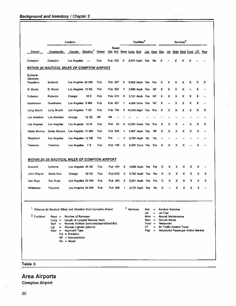
High land values and extensive urban development limit the number ofnearby airport. Table 3 lists the eight public-use airport located within20 nautical mil~s of Compton Airport. It is anticipated that these eightairport will continue to serve as public-use aviation-related facilities
29
Background and Inventory / Chapter 3
Locon Facilties2 Service3
BaAirport Community County Direcon 1 Owner Use NC ~ Lon!! Surf .! ~ Gas Jet Mntn Rent Foo £L ~
Compton Compton Los Angeles Pub Pub 352 2 3.670 Asph Yes Vis X X X X
WITHIN 20 NAUTICAL MILES OF COMPTON AIRPORT
Burbank-Glendale-Pasadena Burbank Los Angeles 20 ~ Pub Pub 327 2 6,902 Asph Yes Pre X X X X X X X
EI Monte EI Monte Los Angeles 15 NE Pub Pub 525 3.995 Asph Yes NP X X X X X
Fullerton Fullerton Orange 13 E Pub Pub 575 3 3,121 Asph Yes NP X X X X X X
Hawthorne Hawthorne Los Angeles 5~ Pub Pub 307 4.956 Conc Yes NP X X X X X
Long Beach Long Beach Los Angeles 7 SE Pub Pub 700 5 10,00 Asph Yes Pre X X X X X X X
Los Alamitos Los Alamitos Orange 12 SE Mil Mil
Los Angeles Los Angeles Los Angeles 10W Pub Pub 22 4 12,091 Conc Yes Pre X X X X X X
Santa Monica Santa Monica Los Angeles 15 ~ Pub Pub 552 4,987 Asph Yes NP X X X X X X
Shepherd Los Angeles Los Angeles 13 NE Pv Pv 2,700 Asph No Vis
Torrance Torrance Los Angeles 7 S Pub Pub 756 2 5,00 Conc Yes Pre X X X X X
WITHIN 20-25 NAUTICAL MILES OF COMPTON AIRPORT
Brackett laVerne Los Angeles 25 NE Pub Pub 484 2 4,839 Asph Yes Pre X X X X X X
John Wayne Santa Ana Orange 22 SE Pub Pub103 2 5,700 Asph Yes Pre X X X X X X X
Van Nuys Van Nuys Los Angeles 23 ~ Pub Pub 96 2 8,001 Asph Yes Pre X X X X X X X
Whiteman Pacoima Los Angeles 24 ~ Pub Pub 66 3,725 Asph Yes Vis X X X X X
1 Distance On Nautical Miles) and Direction from Compton Airprt 3 Service: GasJetMntnRentFooCTPsgr
Aviation GaslineJet Fuel
Aircraf MaintenanceAircraf RentaReurantAir Traffc Control TowerScheduled Pasnger Airline Service
2 Facilties: RwsLongSurfLgtAppr
Numbe of RunwaysLength of Longest Runway (feet)Runway Surface (concrete/asphall/rf/dirt)Runway Ughted (yes/no)Approach Type
Pre = Precision
NP = Non-precisionVis = Visual
Table 3
Area AirportsCompton Airport
30
Background and Inventory / Chapter 3
throughout the 20-year master planning period. No new airport are
expected to be developed within the subject area.
As the listing indicates, a number of these area airport are large, busymetropolitan airport serving complex, high-peiformance general aviation
and air carrier aircraft. Fullerton Municipal, EI Monte, Torrance Munici-pal, and Hawthorne Municipal airport serve somewhat the same generalaviation markets as does Compton Airport. The nearest public-use air-port to Compton are Long Beach, Hawthorne Municipal, and Torrance
Municipal, each located approximately five miles from Compton Airport.All of these airport offer a wide range of sophisticated aviation services
and capabilities and are oriented to serving high-peiformance generalaviation aircraft.
Area Ai rs pace
The primary components of the airspace in the vicinity of Compton Air-port are depicted in Figure 7. Not surprisingly, the airspace in the vicinityof Compton Airport is highly complex - typical of a major metropolitanarea with numerous busy airport. The significant airspace features pres-ently impacting Compton Airport operations include:
· Controlled Airspace - Overlies Compton Airport area at a height of700 feet above the suiface.
· Los Angeles Terminal Control Area (TCA) - Overlies ComptonAirport between the altitudes of 5,000 feet and 12,500 feet Mean SeaLevel (i.e., between 4,903 feet and 12A03 feet above the Airport'ssuiface).
· Los Angeles 30NM Mode C Requirement Area - Compton Airportlies within this area and, as a result, virtually all aircraft operatingto/from Compton Airport must be equipped with an operating Mode Ctransponder.
· Long Beach Airport Traffc Area (ATA) - Located approximately 1.5
nautical miles southeast of Compton Airport from the surface to 3,057feet above Mean Sea LeveL. It can be anticipated that, at some pointin the near future, an Airport Radar Service Area (ARSA) will be estab-
lished serving Long Beach Airport.
· Hawthorne Municipal Airport Traffc Area (A TA) - Located approxi-mately two nautical miles northwest of Compton Airport from thesurface to 3,063 feet above Mean Sea LeveL.
· Torrance Municipal Airport Traffc Area (ATA) - Located approxi-
mately five nautical miles southwest of Compton Airport from thesuiface to 3,101 feet above Mean Sea LeveL.
31
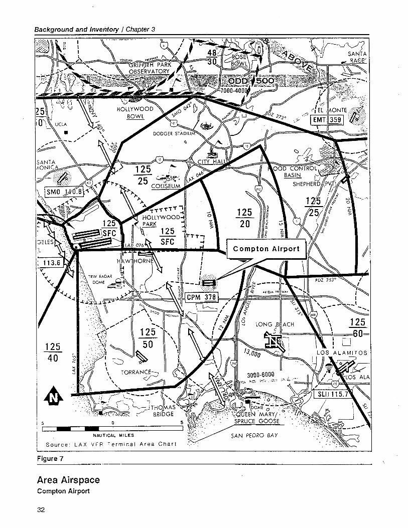
Background and Inventory / Chapter 3
I
12540 '"
""
"".:
i
i 5: I
I
Source: LAX Area Chart
Figure 7
Area AirspaceCompton Airport
32
Background and Inventory / Chapter 3
Aircraft operating to/from Compton Airport must remain clear of theabove-noted TCA and ATA's until communications have been establishedwith Air Traffic Control and an air traffic clearance is received.
Compton Airport is not equipped with an airport traffc control tower.Compton is the only public-use airport in the Los Angeles basin without acontrol tower.
COMMUNITY PROFILE
Th.e area surrounding Compton Airport is comprised of high-densitysingle- and multi-family residences and commercial/industrial develop-ment. A 4.5-acre public park is located adjacent to the Airport's south-west corner. In addition, several schools are located within two miles ofthe Airport. Much of the development in the area dates back to the1950's and 1960's. The only relatively new development has been tothe east and northeast of the Airport - primarily two-story residences.
PREVIOUS AIRPORT PLANS AND STUDIES
Apart from its inclusion in regional and system-wide Los Angeles areaairport studies, Compton Airport has not been the subject of any specificplanning studies. However, in 1963, an analysis of site alternatives toCompton Airport's present location was conducted by the County. Al-though an alternative site was recommended, no action to relocate theAirport was ever taken.
The Airport's existing Airport Layout Plan (ALP) was prepared by the LosAngeles County Department of Public Works in August 1966. The exist-ing ALP is superseded by the new ALP identified herein.
This Compton Airport Master Plan Report (1991) is the first comprehen-sive contemporary study of the Airport - its functional role, operations,configuration, and development.
33

34
,
.~-
~Airport Activity
andCapacity Analysis
.
4
Airport Activity andCapacity Analysis
AIRPORT ROLE
Historical
Compton Airport's principal operational role within the Los Angeles Cou-nty regional airport system has historically been as a public-use airport forbased and transient general aviation aircraft. The large majority of aircraftutilizing Compton Airport do so for personal, recreational, business, andflght training purposes.
Particularly noteworthy is the relatively high percentage (approximately35%) of Compton Airport-based aircraft that are considered "enthusiast'aircraft. The "enthusiast' classification includes antique, classic, sport,amateur-built, and warbird aircraft types. This high percentage of Comp-ton-based "enthusiast' aircraft may be attributable to the absence of acontrol tower at the Airport (i.e., no two-way communication radio isrequired), the relatively less complex airspace operating environment inthe immediate vicinity of Compton Airport, the availability of small aircraftstorage hangars, and the relatively lower cost of operating a private air-craft at Compton Airport (e.g., lower aircraft equipment costs, storagecosts, and fuel costs) as compared with other airport in the central LosAngeles area.
In addition, the Airport has seen considerable use as a location for gener-al aviation flght training activity - primarily full-stop takeoffs and landings(touch-and-go's are prohibited at the Airport by County regulation) - byboth based and transient aircraft operators.
The Airport has also served the area air access needs of the local businesscommunity, particularly those businesses operating the same types ofaircraft most commonly used for personal flying (i.e., single-engine andlight twin-engine, piston-powered airplanes). The recent development ofthe nearby Highway 91 industrial corridor has contributed to much of thisincreased business and corporate aircraft activity.
35
Airport Activity and Capacity Analysis / Chapter 4-
Personal/recreational flying isdefined as the use of aircraft byindividuals (in their own or rent-ed aircraft) for pleasure, recre-ational, or personal transporta-
tion not in furtherance of theiroccupation or company busi-ness.
Business flying is defined as theuse of aircraft by pilots (not re-ceiving direct salary or compen-sation for piloting) in connectionwith their occupation, their
employer's business, or in thefurtherance of private business.
Corporate flying is defined asthe use of aircraft owned or
leased, and operated by a cor-poration or business firm for thetransportation of personnel orcargo and in furtherance of thecorporation's or firm's business,and which are flown by profes-sional pilots receiving a directsalary or compensation for pilot-ing.
36
Further contributing to the Airport's overall activity are increased opera-tions by rotary-wing aircraft - generated by both based and transienthelicopter operators. The majority of this rotary-wing aircraft activity isgenerated by the City of Compton Police Department - Air SupportDivision, which currently bases three active helicopters (two piston-pow-ered Enstrom F-28's and one turbine-powered MD-500E) at ComptonAirport.
Future
For the foreseeable future, it is anticipated that the operational role ofCompton Airport will remain essentially the same as in the past. That is,the Airport will continue to serve as a base of operations and destinationfor primarily personal and recreational aircraft. Flight training operationswill continue to contribute substantially to the Airport's overall activity. Inaddition, operators of business and corporate aircraft of the single-engineand light twin-engine class will make increasing use of Compton Airportas an alternate to the larger, more complex airport in the area (e.g., LosAngeles International Airport and Long Beach Airport). Due to the in-creasing cost and complexity of general aviation operations in urbanareas, it can be anticipated that the Airport user population will experi-ence a shift towards more highly utilized, better-equipped, more sophisti-cated general aviation aircraft in the next 5-10 years.
Supplementing this fixed-wing aeronautical activity at Compton Airportwill be an increase in helicopter activity, particularly flight operationsgenerated by the City of Compton Police Department helicopter unit andCompton Airport fixed base operators. Additional helicopter activity willbe generated by local municipalities who choose to base their public-service (i.e., police, fire, emergency response, and community support)helicopters at Compton Airport.
Beyond the Master Plan's 20-year time frame, it can be anticipated thatCompton Airport will continue to serve as an importnt public aeronauti-cal facility for the central Los Angeles area. Although it is difficult topredict the specific role and use of the Airport beyond the year 2010, itcan be anticipated that the Airport propert and facilities will prove to beof considerable value and utility to the community in responding to futurepublic air transporttion needs.
".- -
Airport Activit and Capacit Analysis / Chapter 4
HISTORICAL AIRPORT ACTIVITY
Based Aircraft
Total Counts
-;:
The number of aircraft based at Compton Airport increased between theyears 1980 and 1988 - from a low count of 338 in 1980 to an all-timepeak count of 467 in 1988. Since 1988, the number of based aircrafthas declined to a current count of 352. Factors which have influenced
this recent decline in based aircraft include the n~tional and regionaldecreases in general aviation activity, particularly in the personal/recre-ational aircraft market segment, and the increasing complexity and costsassociated with aircraft operations in high-density urban areas. Figure 8illustrates the historical based aircraft count for the years 1970-1990 atCompton Airport.
Type of Aircraft
As is typical of most general aviation airport, the dominant type of air-craft based at Compton Airport is single-engine, propeller-driven, piston-powered airplanes - comprising 93% of the total. Twin-engine, propel-ler-driven, piston-powered airplanes based at the Airport comprise 6% ofthe total. The other 1 % consists of helicopters. No turbine-poweredfixed-wing airplanes are regularly based at the Airport.
Ownership Distribution
The based aircraft users of Compton Airport are predominantly Los Angel-es County residents or businesses. According to the County's listing ofbased aircraft owners, 94% of the based aircraft are registered to ownersfrom the Los Angeles County area, with 5% of the Airport's based aircraftregistered to residents and businesses located in the City of Compton.
Aircraft Operations
Estimates of annual aircraft operational activity at Compton Airport havebeen recorded by the County only since 1987. Prior to that period, noestimates of annual aircraft activity at Compton Airport were maintained.However, from the various sources which are available, it is possible todevelop a useful estimate of past aircraft activity. Historical data listed invarious FAA, state, and local sources indicates that total airport activityhas remained relatively constant over the past three years. Prior to 1986,operational activity estimates were significantly higher than those of recentyears. These higher estimates may be the result of overly optimistic
.37
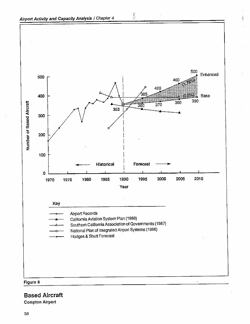
0;-
Airport Activity and Capacity Analysis / Chapter 4
soo500
Enhanced
400 Base==co~u~~
300'C
5!coII-0
200~Q).tE::z
100
c Historical Forecast ..
0
1970 1975 1980 1985 1990 1995 2000 2005 2010
Year
Key
Airprt Records~ California Aviation System Plan (1988)
lò Southern California Association of Govemments (1987)
-0 National Plan of Integrated Airport Systems (1986)
Hodges & Shutt Forecast
Figure 8
Based AircraftCompton Airport
38
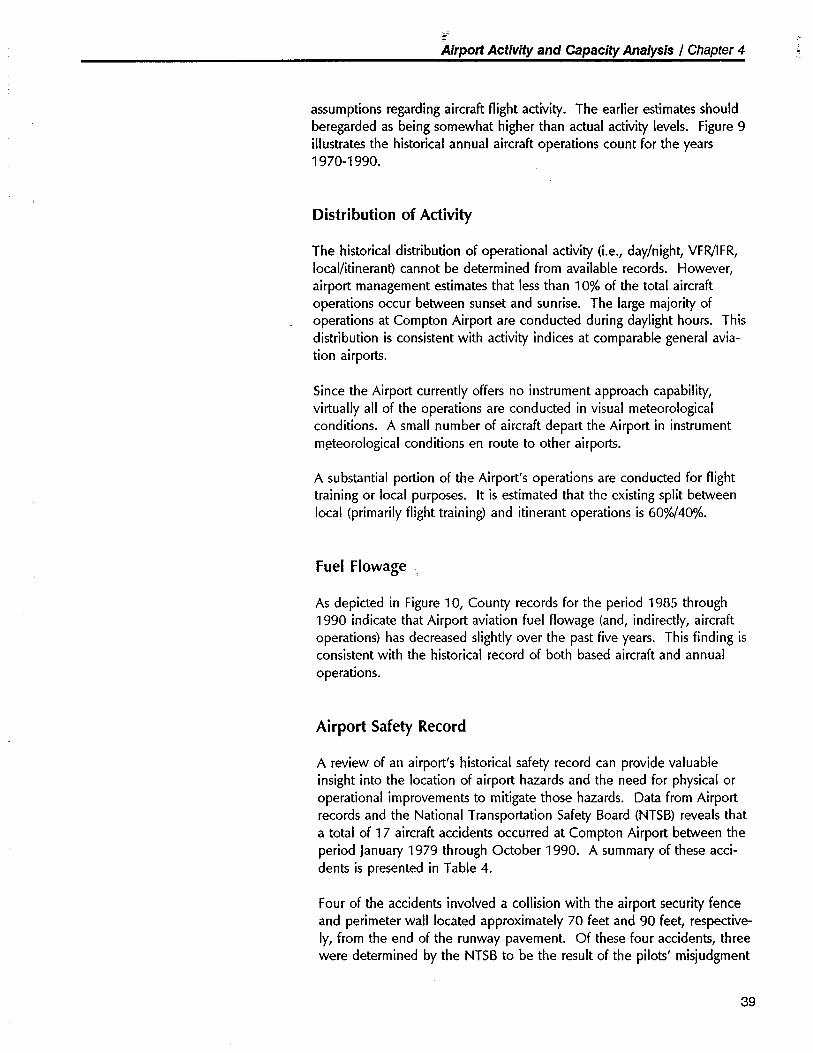
Airport Activity and Capacity Analysis / Chapter 4
assumptions regarding aircraft flight activity. The earlier estimates shouldberegarded as being somewhat higher than actual activity levels. Figure 9illustrates the historical annual aircraft operations count for the years1970-1990.
Distribution of Activity
The historical distribution of operational activity (i.e., day/night, VFR!IFR,
local/itinerant) cannot be determined from available records. However,airport management estimates that less than 10% of the total aircraftoperations occur between sunset and sunrise. The large majority ofoperations at Compton Airport are conducted during daylight hours. Thisdistribution is consistent with activity indices at comparable general avia-tion airport.
Since the Airport currently offers no instrument approach capability,virtually all of the operations are conducted in visual meteorologicalconditions. A small number of aircraft depart the Airport in instrumentm~teorological conditions en route to other airport.
A substantial portion of the Airport's operations are conducted for flighttraining or local purposes. It is estimated that the existing split betweenlocal (primarily flight training) and itinerant operations is 60%/40%.
Fuel Flowage
As depicted in Figure 10, County records for the period 1985 through1990 indicate that Airport aviation fuel flowage (and, indirectly, aircraftoperations) has decreased slightly over the past five years. This finding isconsistent with the historical record of both based aircraft and annualoperations.
Airport Safety Record
A review of an airport's historical safety record can provide valuableinsight into the location of airport hazards and the need for physical oroperational improvements to mitigate those hazards. Data from Airportrecords and the National Transporttion Safety Board (NTSB) reveals that
a total of 17 aircraft accidents occurred at Compton Airport between theperiod January 1979 through October 1990. A summary of these acci-dents is presented in Table 4.
Four of the accidents involved a collsion with the airport security fenceand perimeter wall located approximately 70 feet and 90 feet, respective-ly, from the end of the runway pavement. Of these four accidents, threewere determined by the NTSB to be the result of the pilots' misjudgment
39
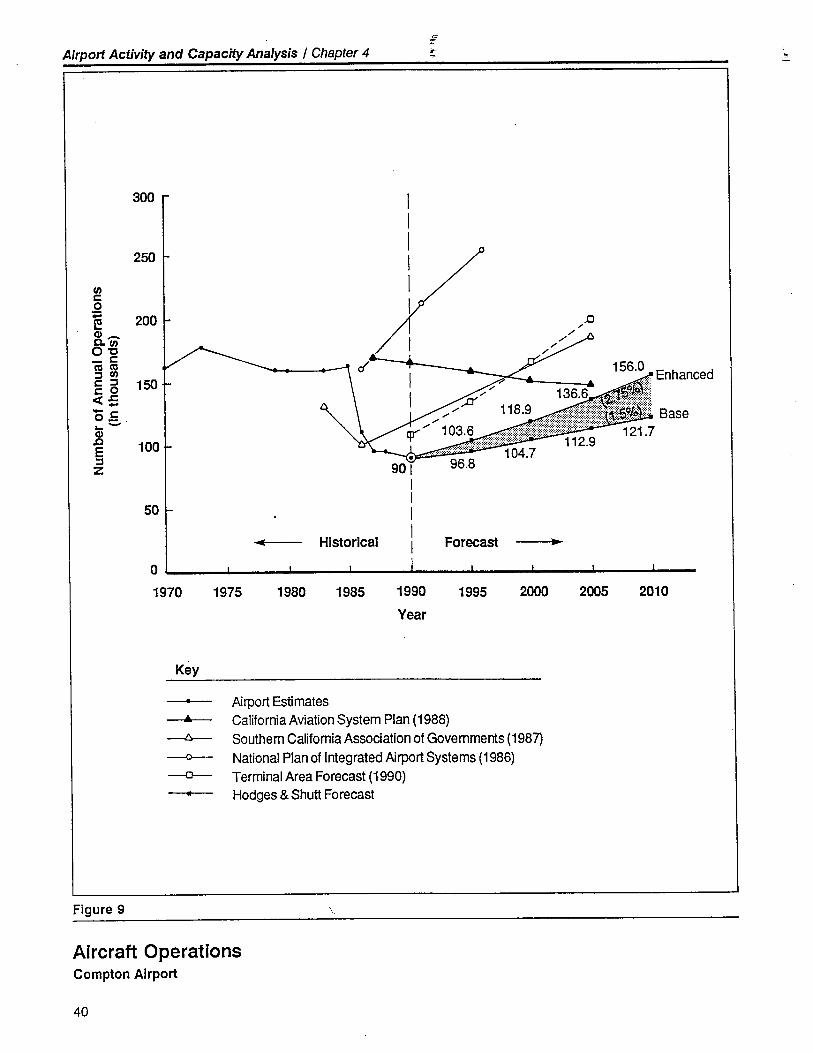
Airport Activity and Capacity Analysis / Chapter 4~r- -
300
250
uui:0;: 200~C1 _C. uu0'0_ i:ct ct:J uui: :J 150i: 0cc ..-- i:0_..-C1J: 100E:JZ
50
o
1970 1975
.90 I
I
I
I
HistoricalI
Forecast..I
..
1980 1985 1990 1995 2000 2005 2010
Year
Key
--Airport Estimates
California Aviation System Plan (1988)
Southern CalifomiaAssociation of Governments (1987)National Plan of lntegrated Airprt Systems (1986)Terminal Area Forecast (1990)Hodges & Shutt Forecast
..Â-0.
Figure 9 -.
Aircraft OperationsCompton Airport
40
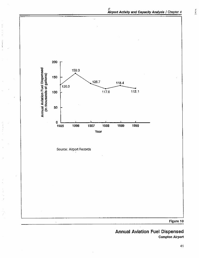
.~-
Âirport Activity and Capacity Analysis / Chapter 4
200
-g 159.3IIc-C1 II 150c. cII .2em 118.4_ ccC1_:) 0LL II
100 117.0 112.1c '0o C- C'16 II- :)~ ,g--
50C' c:) -c-cc(
01985 1986 1987 1988 1989 1990
Year
Source: Airport Records
Figure 10
Annual Aviation Fuel DispensedCompton Airport
41
=
Airport Activity and Capacity Analysis / Chapter 4 r-~ .,
Date: January 1979 through Ocober 1990 2/10/79 9/16/79 9/16/79 2/13/80 3/8/81
Type of AircraftBellanca Cessna Cessna Piper Cessna
14-13 150 150 PA-23 152
Stationary/taxiing
Takeoff - run
Takeoff - initial climb X
Landing - in traffc pattern
Landing - in final approach X X X
Landing - touchdown/roll out X
Hard landin&igear up/ground loop/etc.
U ndershoot/ overshoot
Collision with object
Forced landing
Uncontrolled descent/impact
Collision between aircraft in flght
X
X
X
X X X
On/adjacent to runway
Runway/Protection Zone
In approach zone
On airport propert
X X
X X
Pilot - improper operation of controls
Pilot - failure to see/avoid object
Pilot - inadequate preflght procedures
Fuel exhaustion
Mechanical failure
Adverse wind/weather
X X
X X
X
Time (local)
Visibilty (S.M.)
Student pilot
Injuries (yes/no)
Fatalities (yes/no)
Oter
1605
NO
YES
1040 1040
X X
NO NO
NO NO
1330 1340
YES
NO
YES
NO
Table 4
Summary of Aircraft AccidentsCompton Airport
42
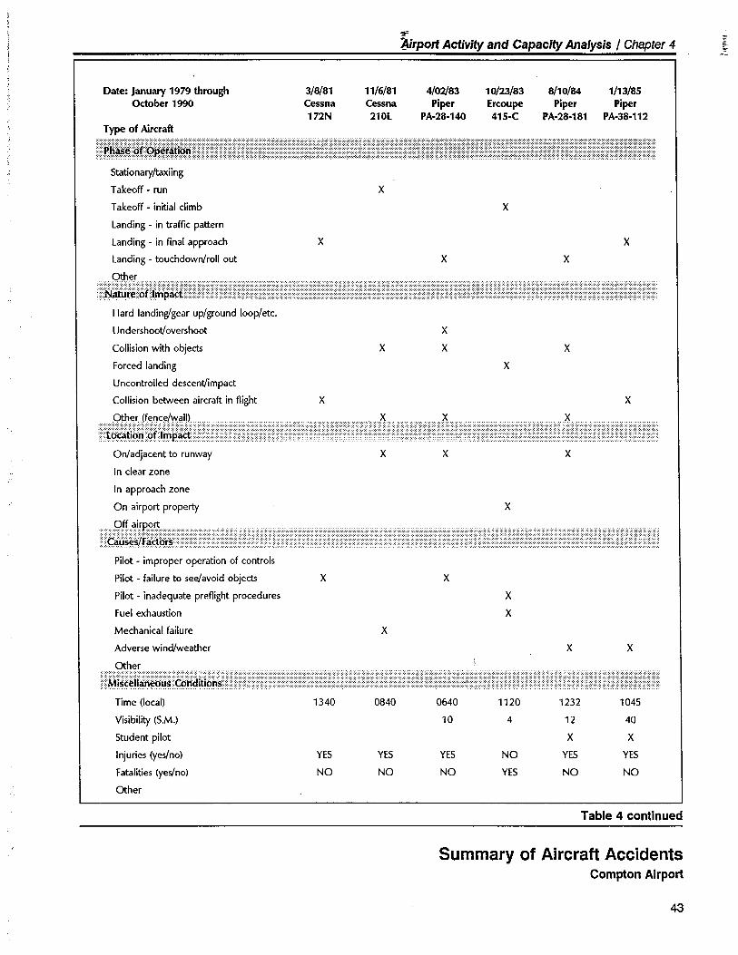
~~rport Activit and Capacit Analysis / Chapter 4 ;,
Date: Januar 1979 through 3/8/81 11/6/81 4/02/83 10/23/83 8/10/84 1/13/85October 1990 Cessna Cessna Piper Ercoupe Piper Piper
172N 210l PA-28-140 415-C PA.28.181 PA.38.112Type of Aircraft
Stationary/taiing
Takeoff - run X
Takeoff - initial climb X
landing - in traffc pattern
landing - in final approach X X
landing - touchdown/roll out X X
Hard landing/gear up/ground loop/etc.
Undershoot/overshoot
Collsion with object
Forced landing
Uncontrolled descent/impact
Collsion between aircraft in flght
X
X
X X
X
X X
On/adjacent to runway
In clear zone
In approach zone
On airport propert
X X X
X
Pilot - improper operation of controls
Pilot - failure to see/avoid object
Pilot - inadequate preflght procedures
Fuel exhaustion
Mechanical failure
Adverse wind/weather
X X
X
X
X
X X
Time (local)
Visibility (S.M.)
Student pilot
Injuries (yes/no)
Fatalities (yes/no)
Oter
1340 0840
YES
NO
YES
NO
0640 1120 1232 1045
10 4 12 40
X X
YES NO YES YES
NO YES NO NO
Table 4 continued
Summary of Aircraft AccidentsCompton Airport
43
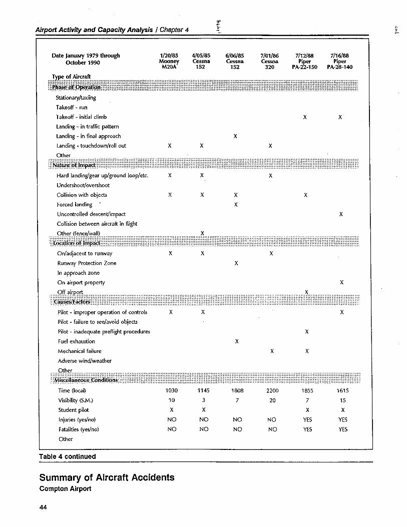
Airport Activit and Capacity Analysis / Chapter 4-r
~
Date January 1979 throughOctober 1990
1/20/85Mooney
M20A
4/05/85Cessna
152
6/06/85Cessna
152
7/01/86Cessna
320
7/12/88Piper
PA-22-150
7/16/88Piper
PA-28-140
Stationary/taxiing
Takeoff - run
Takeoff - initial climb
Landing - in traffc pattern
Landing - in final approach
Landing - touchdown/roll out
x x
x
x x x
Hard landing/gear up/ground loop/etc.
Undershoot/overshoot
Collsion with object
Forced landing
Uncontrolled descent/impact
Collsion between aircraft in flght
x x x
x x x
X
X
X
On/adjacent to runway
Runway Protection Zone
In approach zone
On airport propert
X X X
X
X
Pilot - improper operation of controls
Pilot - failure to see/avoid object
Pilot - inadequate preflght procedures
Fuel exhaustion
Mechanical failure
Adverse wind/weather
X X X
X
x
x x
Time (local) 1030 1145 1808 2200 1855 1615
Visibilty (S.M.) 10 3 7 20 7 15
Student pilot X X X X
Injuries (yes/no) NO NO NO NO YES YES
Fatalities (yes/no) NO NO NO NO YES YES
Oter
Table 4 continued
Summary of Aircraft AccidentsCompton Airport
44
~Áirport Activit and Capacity Analysis / Chapter 4 ..
and inappropriate operation of their aircraft. The fourth accident was theresult of an undetermined powerplant failure and subsequent abortedtakeoff.
Although this represents a relatively high number of accidents, there areno findings or indications that airport facilities or operational procedurescontributed to any of the accidents. One of the factors which influencesthis high number of accidents is the high percentage of personal, recrea-tional, and flight training operations that characterize the bulk of Comp-ton Airport's aeronautical activity.
BASED AIRCRÅFT DEMÅND FORECÅSTS
Current and future demand for based aircraft parking space, both inhangars and tiedowns, at Compton Airport is influenced by a variety offactors. Some of these are national or regional in character, others arespecific to Compton Airport. Each of these demand factors needs to beconsidered in the development of based aircraft forecasts for the Airport.
National and Regional Demand Factors
National and regional influences on local based aircraft demand aresignificant in that they are external influences, beyond the direct controlof the Airport. Among these influences are:
· Aircraft Ownership Trends - The current nationwide pattern oflimited growth in the general aviation fleet is one of the strongestinfluences on future based aircraft demand in the Southern Californiaregion. Only 8% as many aircraft were built in the U.S. in 1989 as in1978. Many reasons have been cited for this trend:
- The high cost of new aircraft, partially due to high product liabilitycosts.
- High aircraft operational and maintenance costs.
- Airspace and airport operational restrictions in metropolitan areas.- The complexity of aircraft and of flight regulations.- The lack of simple, efficient, and comfortble new aircraft.
Although some recovery is projected over the next five to ten years, itis expected to be very slow. Current Federal Aviation Administrationforecasts indicate that the nation's active general aviation fleet willgrow at an annual rate of only 0.5% over the next 12 years (FAA -1990). Active single-engine, piston-powered aircraft are projected todecline at an annual rate of approximately 0.1 % during the next fiveyears and then maintain a zero growth rate through the year 2000.The strongest area of growth is in business and corporate aircraft,
45
Airport Activity and Capacity Analysis / Chapter 4.=~.. ~
~~
especially sophisticated turbine-powered aircraft. This latter group isprojected to increase by 54% over the next 12 years, compared to theexpected zero growth rate in personal and recreational type aircraft.These national figures vary somewhat by region. The FAA forecasts forthe Western-Pacific region indicate that the growth in based aircraftwill be relatively strong, with a growth rate nearly double that of thecountry as a whole. Even so, the general aviation rate of growth willbe very modest.
The obvious consequence of these conditions is that, for any particularairport to have a significant increase in based aircraft, it must attractmore business and corporate aircraft, or it must gain additional person-al and recreational based aircraft from other airport. This can resultfrom changes in the relative advantages of one airport over another orthe closure of an airport.
· Regional Aircraft Growth Trends - The number of aircraft basedwithin the Southern California region decreased by approximately 1 %
between 1984 and 1987. The Southern California Association ofGovernments (SCAG) forecasts that the number of aircraft based in theSCAG region will increase at an annual rate of 1 % for the next 18years (SCAG - 1987). This overall forecast was broken down into twocategories:
- Urban Core Airport, airport at full capacity and busy, are forecastto lose based aircraft over the next eight years, and then hold evenfor the remaining ten years. Compton Airport is classified by SCAGas an "Urban Core Airport."
- Fringe and Remote Airport, airport with excess capacity and notas busy, are projected to grow slowly over the next several years,accelerating to a growth rate of 2% per year from 1995 to 2005.
Specific Compton Airport Demand Factors
The remaining demand influences partially overlap the above regionalfactors, but are more specific to the conditions existing at Compton Air-port.
· Airport Role - As noted above, the growth potential of ComptonAirport's primary user group - personal and recreational use aircraft -is projected to be very limited. High aircraft operational costs and
increasing airspace complexity may cause some marginal personal andrecreational aircraft users to dispose of their aircraft or relocate themto other, less costly and less complex facilities.
· Facilities and Services Available - Existing facilities and services atCompton Airport, particularly runway length and approach instrumen-tation, are somewhat below average compared to other public airport
46
fi~
Airport Activit and Capacit Analysis / Chapter 4
~
¡,
in the central Los Angeles area. This is judged to have negative impli-cations with respect to forecasting future demand potentiaL. Due tophysical limitations, there is only a modest opportunity to improveCompton's relative attractiveness to users of sophisticated, high-perfor-mance business and corporate aircraft.
· Demand for Hangar Space - Increasingly more sophisticated andexpensive equipment is being added to,aircraft. Thus, more ownersare seeking hangar storage space for their aircraft. Compton Airportcurrently has 166 T-hangar units. It is anticipated that any significantincrease in the number of based aircraft will be driven in part by theavailability of additional aircraft storage hangars.
· Airspace/Equipment Complexity - Compton Airport is located withinthe 30-nautical-mile Mode C requirement arc associated with LosAngeles International Airport. Most aircraft operating in the vicinity ofCompton Airport are required by federal regulation to be equippedwith a Mode-C altitude-reporting transponder (only aircraft originallycertificated without electrical systems are exempt). This recent re-quirement has caused some owners of non-Mode C equipped aircraftto relocate to airport beyond the 30-nautical-mile Mode C arc. Inaddition, the Los Angeles Terminal Control Area (TCA) overlies Comp-ton Airport at an elevation of 5,000 feet MSL (approximately 4,900feet above airport elevation). This complex multi-layered airspace
configuration undoubtedly has caused some aircraft owners to relocatetheir aircraft to outlying, less complex airport. It can be anticipatedthat the airspace structure and operating requirements in the vicinity ofCompton Airport will become increasingly more complex and restric-tive in the years ahead. Potential changes in FAA airspace allocationscould result in Compton Airport being further encroached upon by areconfigured Hawthorne Municipal Airport Traffic Area (AT A), a newly-formed Long Beach Airport Radar Service Area (ARSA), and, at somepoint in the future, a "Super TCA" encompassing much of the LosAngeles Basin airspace.
· Nearby Airport - Los Angeles International, Long Beach, Torrance
Municipal, and Hawthorne Municipal Airport are located within 1 0nautical miles of Compton Airport, creating a highly competitive avia-tion environment. All four of these airport are well-equipped public-use airport capable of serving a wide variety of sophisticated generalaviation piston and turbine-powered aircraft, particularly those usersoperating business and corporate class aircraft. The availability of suchsophisticated nearby facilities has influenced Compton Airport in twosignificant ways. Owners of high-performance and well-equippedaircraft generally prefer one of Compton's competitor airport due tothe availability of longer runways, instrument approach capability, andmultiple ground services. Users of low-performance and less well-equipped aircraft view Compton Airport as a relatively low-cost alter-native to the larger, more complex airport.
47
Airport Activity and Capacity Analysis / Chapter 4~'i ;,
· Proximity to Nearby Industry - Growth of the nearby Highway 91
industrial corridor wil have a positive effect on Compton's aeronauti-cal activity. Small business and corporate aircraft desiring easy accessto the Highway 91 industrial corridor may choose, runway length andapproach instrumentation permitting, to operate to/from ComptonAirport.
· Public-Service Helicopter Activity - Due to the scarcity of suitablehelicopter basing areas in the Los Angeles basin, it is anticipated thatone or more municipalities will choose to base their public-servicehelicopters at Compton Airport. These based helicopters have thepotential to generate a considerable number of operations at the Air-port.
· User Perceptions - Many aircraft users perceive Compton Airport tobe a less-than-desirable location for operating or basing an aircraft.User concerns regarding security, personal safety, and the absence ofviable ground transporttion options are seen as negative growth fac-
tors.
· Marketing Efforts for Compton Airport - A marketing program for
Compton Airport has been prepared as an integral element of thismaster planning effort. Continuous effort to market the Airport's
. facilities, services, and capabilities will significantly influence an in-crease in the number of based aircraft.
Other Based Aircraft Demand Forecasts
Federal, state, and regional forecasts provide another view of possiblefuture based aircraft demand at Compton Airport. Figure 8 provides agraphic comparison of various based aircraft forecasts for Compton Air-port versus historic activity levels. As can be seen, the various forecastsstart from different base year counts and project varying rates of growth.The rapid growth projected by the NPIAS forecast in 1986 was consistent
with the general aviation aircraft forecast expectations prevalent at thetime. The more recent SCAG (1987) and CASP (1988) forecasts projectno growth and a loss of based aircraft, respectively, over the next 15years.
It must be recognized, however, that each of these forecasts is developedin a top-down manner; that is, the forecasts are first determined for therespective geographic area, then allocated to sub-areas and ultimately toindividual airport. Particularly at the federal and state levels, little atten-tion is given to the localized conditions that may influence future activitychanges at a specific airport.
48
~
A-rport Activit and Capacit Analysis / Chapter 4
'=~
"~
Based Aircraft Demand Conclusions
Despite the projected slow growth trend in national and regional generalaviation activity, the Master Plan concludes that there is potential formodest growth of Compton Airport's based aircraft population - bothfixed-wing and rotary-wing aircraft. This assumes that the Airport's facili-ties and services are improved, instrument approach capability is estab-lished, additional hangar space is provided, and the County/COMARCOeffectively market the Airport.
Depicted in Figure 8 is the Master Plan forecast range of future basedaircraft for Compton Airport. The "Enhanced" forecast represents thebased aircraft activity that could be realized if the region's general avia-tion market improves and the above noted actions are taken. The "En-hanced" forecast anticipates a 1.75% annual increase in the Airport'sbased aircraft population. The "Base" forecast represents the based air-craft activity that could be realized if the region's general aviation marketstagnates and the Airport continues to operate with minimal improve-ments. The "Base" forecast anticipates a 0.5% annual increase in theAirport's based aircraft population.
For the purposes of this Master Plan, the "Enhanced" demand forecast isthe appropriate choice. By endeavoring to design and configure the
Airport to adequately accommodate the maximum anticipated demand(i.e., the "Enhanced" forecast), maximum facility development flexibility isensured. At the same time, this forecasting approach does not requirefacility development until such time as it is warranted by actual userdemand. The resultant Master Plan forecasts of based aircraft are depict-ed in Figure 8 and are summarized in Table 5.
The timing of new development should be set to stay just slightly aheadof actual demand. Construction too far in advance of demand providesno near-term return on the investment. Lack of new facility development,on the other hand, may result in fe''\er based aircraft at the Airport thanthe forecasts indicate.
TRANSIENT AIRCRAFT PARKING DEMAND
The demand for transient aircraft parking positions at the Airport is influ-enced by a combination of factors, including those mentioned above withrespect to based aircraft, and those discussed subsequently which affectaircraft operations. The Master Plan forecasts project that peak transientaircraft parking demand will increase by approximately 60% over the 20-year planning period, a rate slightly greater than that projected for basedaircraft growth. Much of this future growth in transient aircraft demand isassociated with the Airport's recently developed user amenities (e.g.,
49
Airport Activity and Capacity Analysis / Chapter 4G=~c-. .~
terminal building, coffee shop, etc.) and wil be somewhat dependentupon the County's implementation of an effective marketing program.
AIRCRAFT OPERATIONS FORECASTS
Forecast Influences
As with based aircraft, the number of aircraft operations at a generalaviation airport is influenced both by national and regional conditionsand by various circumstances specific to each airport. Major influencesimpacting the Compton Airport aircraft operations forecast include:
. National Trends - The factors which determine general aviation
operations levels nationally will also be the overriding influences local-ly. Unlike the essentially flat forecast of active based aircraft, FAA
forecasts project a small increase in the number of hours flown by thegeneral aviation fleet over the next decade. A slight rise in the aver-age number of operations per aircraft can consequently be anticipated.Annual use of turbine-powered aircraft is expected to increase morerapidly than that of piston-powered aircraft.
. Number and Type of Based Aircraft - The minor shift toward pro-portionately more complex single-engine and multi-engine airplanes atthe Airport will tend to push operations upward more rapidly than therate of based aircraft growth. Typically, such aircraft are used morefrequently and thus generate more operations per aircraft.
. Availabilty of Services - Compton Airport's facilities and services areprimarily focused to attract the personal and recreational aircraft oper-ator and small business aircraft operator. Such facilities and servicesinclude general aviation-oriented fixed base operators, a coffee shop,available single-unit storage hangars, and a somewhat less complexoperating environment than at competitive area airport.
. Flight Training - Flight training is currently a significant generator of
aircraft operations at Compton Airport. One primary reason for this isthat Compton Airport has less complex airspace and a somewhat lesscomplex operating environment than nearby alternative airport. Flighttraining activity at Compton Airport is expected to increase in thefuture.
. Exent of Transient Aircraft Use - Additional facilities and amenities
at Compton Airport wil generate increased transient aircraft activity,thereby increasing total aircraft operations. In addition, more transientaircraft operators wil use Compton Airport as an alternative means ofaccessing the central Los Angeles area.
50
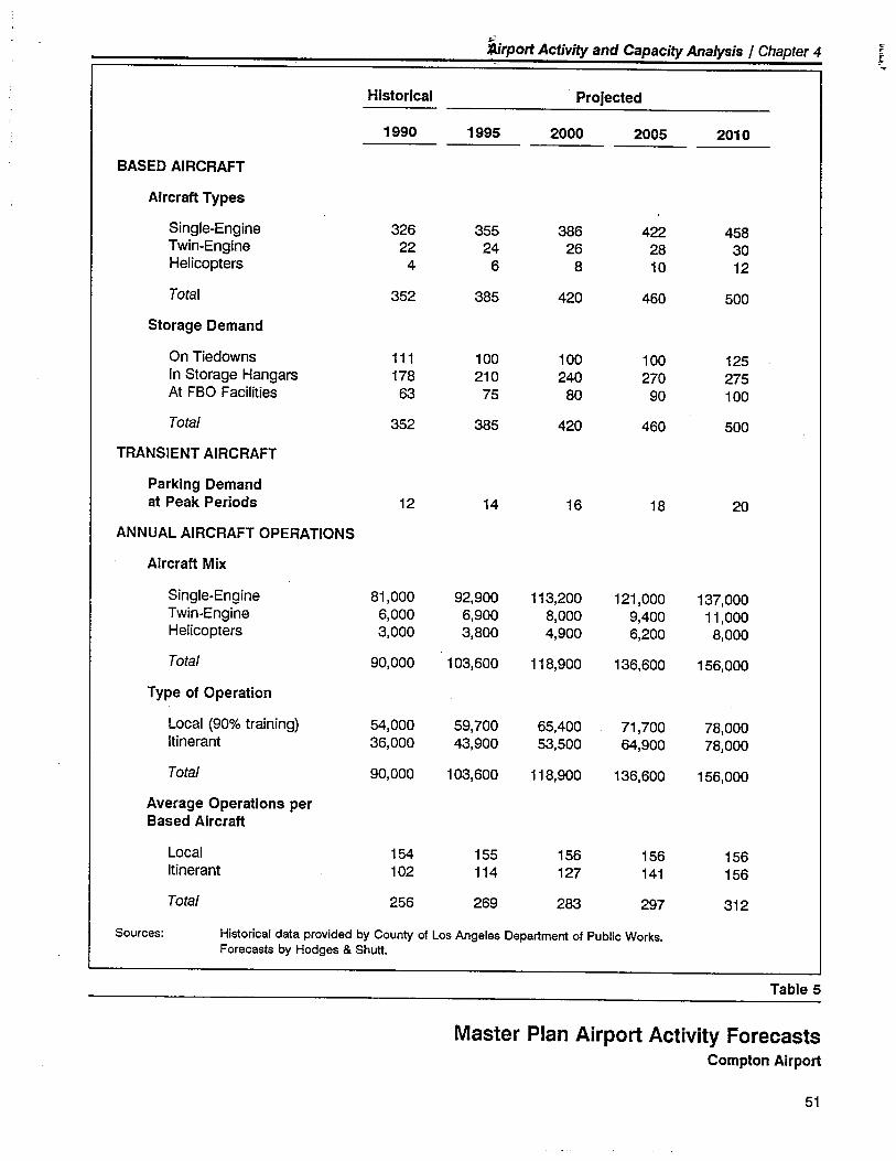
:i'"X!irport Activit and Capacit Analysis / Chapter 4l-~
Historical Projected
1990 1995 .2000 2005 2010
BASED AIRCRAFT
Aircraft Types
Single-Engine 326 355 386 422 458Twin-Engine 22 24 26 28 30Helicopters 4 6 8 10 12
Total 352 385 420 460 500
Storage Demand
On Tiedowns 111 100 100 100 125In Storage Hangars 178 210 240 270 275At FBO Facilties 63 75 80 90 100
Total 352 385 420 460 500
TRANSIENT AIRCRAFT
Parking Demandat Peak Periods 12 14 16 18 20
ANNUAL AIRCRAFT OPERATIONS
Aircraft Mix
Single-Engine 81,000 92,900 113,200 121,000 137,000Twin-Engine 6,000 6,900 8,000 9,400 11,000Helicopters 3,000 3,800 4,900 6,200 8,000
Total 90,000 103,600 118,900 136,600 156,000
Type of Operation
Local (90% training) 54,000 59,700 65,400 71,700 78,000Itinerant 36,000 43,900 53,500 64,900 78,000
Total 90,000 103,600 118,900 136,600 156,000
Average Operations perBased Aircraft
Local 154 155 156 156 156Itinerant 102 114 127 141 156
Total 256 269 283 297 312
Sources: Historical data provided by County of Los Angeles Department of Public Works.Forecasts by Hodges & Shutt.
Table 5
Master Plan Airport Activity ForecastsCompton Airport
51
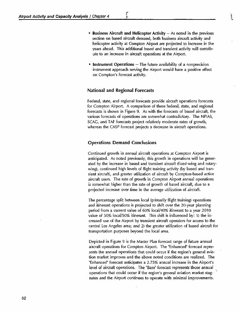
Airpu;t Acti;¡ity and Capacii Analysis / Chapter 4-=.I:.
c
· Business Aircraft and Helicopter Activity - As noted in the previous
section on based aircraft demand, both business aircraft activity andhelicopter activity at Compton Airport are projected to increase in theyears ahead. This additional based and transient activity will contrib-ute to an increase in aircraft operations at the Airport.
· Instrument Operations - The future availability of a non precisioninstrument approach serving the Airport would have a positive effecton Compton's forecast activity.
National and Regional Forecasts
Federal, state, and regional forecasts provide aircraft operations forecastsfor Compton Airport. A comparison of these federa'' state, and regionalforecasts is shown in Figure 9. As with the forecasts of based aircraft, thevarious forecasts of operations are somewhat contradictory. The NPIAS,SCAG, and T AF forecasts project reiativeiy moderate rates of growth,whereas the CASP forecast projects a decrease in aircraft operations.
Operations Demand Conclusions
Continued growth in annual aircraft operations at Compton Airport isanticipated. As noted previously, this growth in operations will be gener-ated by the increase in based and transient aircraft (fixed-wing and rotary-wing), continued high levels of flight training activity (by based and tran-sient aircraft), and greater utilization of aircraft by Compton-based activeaircraft users. The rate of growth in Compton Airport annual operationsis somewhat higher than the rate of growth of based aircraft, due to aprojected increase over time in the average utilization of aircraft.
The percentage split between local (primarily flight training) operationsand itinerant operations is projected to shift over the 20-year planningperiod from a current value of 60% local/40% itinerant to a year 2010value of 50% local/50% itinerant. This shift is influenced by: 1) the in-creased use of the Airport by transient aircraft operators for access to thecentral Los Ange!es area; and 2) the greater utilization of based aircraft fortransportation purposes beyond the local area.
Depicted in Figure 9 is the Master Plan forecast range of future annualaircraft operations for Compton Airport. The "Enhanced" forecast repre-sents the annual operations that could occur if the region's general avia-tion market improves and the above noted conditions are realized. The"Enhanced" forecast anticipates a 2.75% annual increase in the Airport'slevel of aircraft operations. The "Base" forecast represents those annualoperations that could occur if the region's general aviation market stag- -nates and the Airport continues to operate with minimal improvements.
52
trport Activit and Capacit Analysis / Chapter 4¡"rt
Annual Service Volume (ASY) isdefined by the following formula:
ASV = WHC X AU
Where,
ASV = Annual Service Vol-ume in annual opera-tions
WHC = Weighted HourlyCapacity
AU = Annual Utilzation
The "Base" forecast anticipates a 1.5% annual increase in the Airport'slevel of aircraft operations.
For the purposes of this Master Plan, the "Enhanced" demand forecast isthe appropriate choice. Use of the "Enhanced" forecast for Master Plan
projections permits maximum flexibility in the future design, development,and operation of the Airport. The resultant forecasts of annual aircraftoperations are depicted in Figure 9 and are summarized in Table 5.
AIRFIELD CAPACITY ANALYSIS
Background
Airfield capacity is the maximum number of aircraft movements (takeoffsand landings) that can be accommodated in a given period of time undera specific set of conditions related to:
- Runway configuration and use- Mix of aircraft types- Arrival/departure ratio
- Availability and location of runway exits and related taxiway system
- Percentage of training (touch and go) activity- Other factors such as runway conditions (e.g., wet or dry), pilot
performance, and air traffic control procedures
The following discussion is based upon the FAA's most current capacitymethodology as set forth in FAA Advisory Circular 150/5060-5 AirportCapacity and Delay. This is the first known application of this methodol-ogy to Compton Airport. There are two measures of airfield capacity thatare of interest, the Hourly Capacity and the Annual Capacity.
Hourly Capacity
Hourly Capacity is the number of operations a runway system can physi-cally accommodate in an hour. Capacity varies widely under variousoperating conditions (e.g., percentage of arrivals and runway configura-tion).
Annual Capacity
The concept used to measure Annual Capacity in the FAA methodology isAnnual Service Volume (ASV). This concept is based upon the observedphenomenon that, at a certain level of activity, the average delay toaircraft during the year will increase rapidly with relatively small increases
53
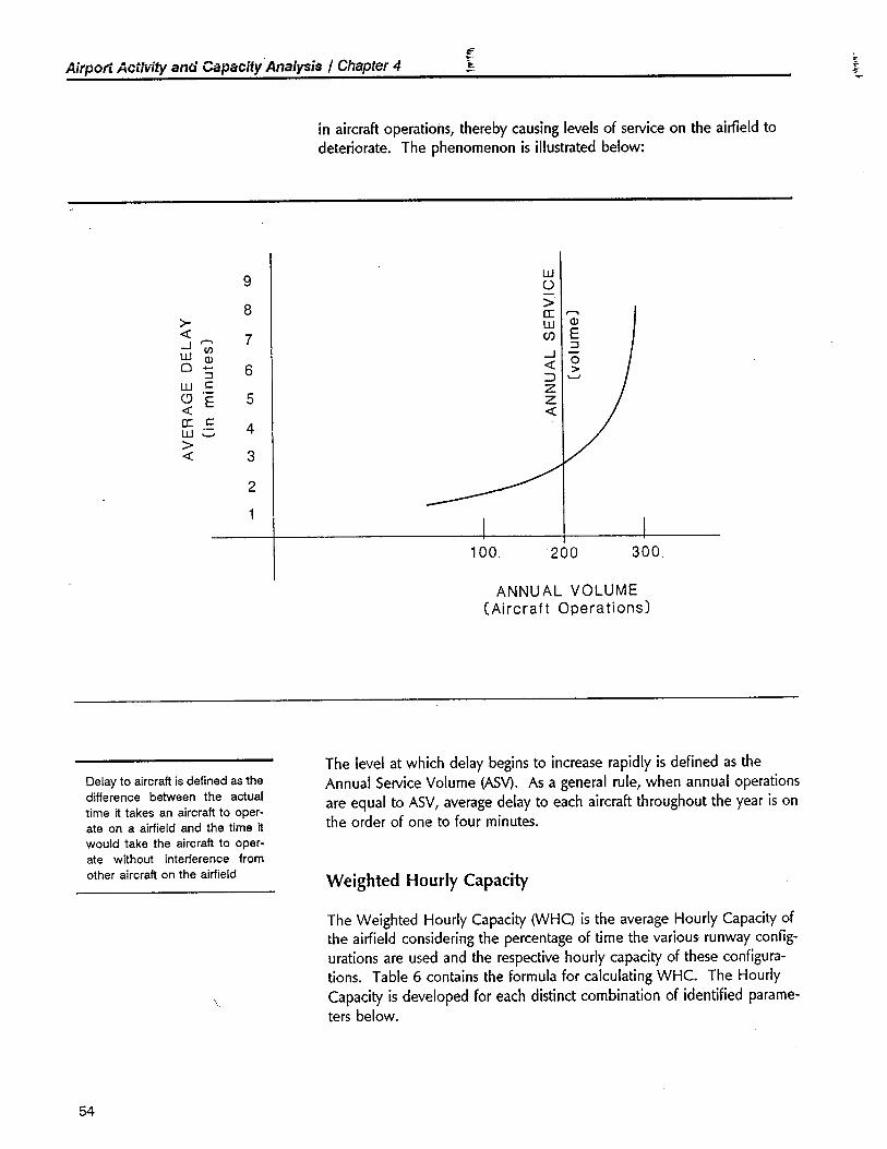
Airpun Aciivity and Capacíiy.Analysis / Chapter 4~ì,. t.
in aircraft operations, thereby causing levels of service on the airfeld todeteriorate. The phenomenon is ilustrated below:
9w0-
8~a: ,.
~ w Q)
-0 7 CJ E,.-- (/ ::W Q)
-- 00 - 6 -0 :;:: :) '-w c: Z(' E 5 z-0 -0a: c:
4w .-'-~-0 3
2
100. 200 300
ANNU AL VOLUME(Aircraft Operations)
Delay to aircraft is defined as thedifference between the actualtime it takes an aircraft to oper-ate on a airfield and the time itwould take the aircraft to oper-ate without interference from
other aircraft on the airfield
The level at which delay begins to increase rapidly is defined as theAnnual Service Volume (ASV). As a general rule, when annual operationsare equal to ASV, average delay to each aircraft throughout the year is onthe order of one to four minutes.
Weighted Hourly Capacity
The Weighted Hourly Capacity (WHO is the average Hourly Capacity ofthe airfield considering the percentage of time the various runway config-urations are used and the respective hourly capacity of these configura-tions. Table 6 contains the formula for calculating WHC. The HourlyCapacity is developed for each distinct combination of identified parame-ters below.
54
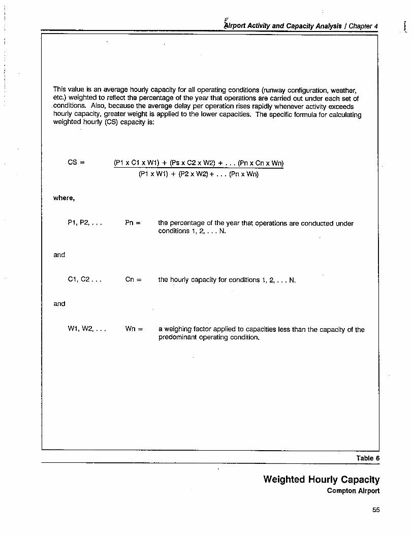
€
lirport Activity and Capacit Analysis / Chapter 4.i
This value is an average hourly capacit for all operating conditions (runway configuration, weather,etc.) weighted to reflect the percentage of the year that operations are carried out under each set of. conditions. Also, because the average delay per operation rises rapidly whenever activity exceedshourly capacity, greater weight is applied to the lower capacities. The specific formula for calculatingweighted hourly (CS) capacit is:
CS = (P1 x C1 x W1) + (Ps x C2 x W2) + . . . (Pn x Cn x Wn)
(P1 x W1) + (P2 x W2) + . . . (Pn x Wn)
where,
P1, P2, . . . Pn = the percentage of the year that operations are conducted underconditions 1, 2, . . . N.
and
C1, C2... Cn = the hourly capacity for conditions 1, 2, . . . N.
and
W1, W2,... Wn = a weighing factor applied to capacities less than the capacity of thepredominant operating condition.
Table 6
Weighted Hourly CapacityCompton Airport
55
Airport Activity and Capacity Analysis / Chapter 4IF~r" ~
· Runway Configuration - Compton Airport offers two equal-lengthparallel runways (7U25R and 7R/25L) separated by 200 feet. The FAAhas two standards for parallel runway separation: one for planning(currently 700 feet); the other for air traffic control handling of inde-pendent, simultaneous visual operations (300 feet for single-engineand 500 feet for twin-engine aircraft). The implication for ComptonAirport is that its two runways are not capable of supporting simulta-neous operations; the two runways acting together create more airfieldcapacity than a single runway but not twice as much.
There are also two directions in which the runways can be operated,to the west and to the east. The two directions are treated as separateconfigurations reflecting the relative differences in exit location withrespect to the landing threshold.
For airfield capacity calculation purposes, three alternative futurerunway configurations were evaluated:
- The existing parallel runway configuration- A single runway using one of the two existing runway centerlines- A single runway using a new centerline, located between the two
existing runways
The second configuration represents two separate alternatives from afacility/building area layout standpoint; the relative merits are dis-cussed elsewhere in this report. From an airfield capacity perspective,however, they are essentially equivalent and can be treated as a singlealternative.
· Runway Exits - During landing, aircraft spend varying lengths of timeon the runway, depending upon the number and location of exits.The average runway occupancy time affects the spacing between ,operations and, therefore, the Hourly Capacity. At Compton Airport,three exit scenarios were evaluated: (1) existing; (2) optimum use ofangled exits with widened fillets; and (3) a continuous drift-off exitsystem similar to that employed at the EI Monte Airport.
· Aircraft Mix - Aircraft mix affects capacity because different aircraft
types have different approach/departure speeds and separation criteria.The FAA classifies aircraft into four categories: A, B, C, and D. Thefollowing tabulation gives criteria and typical aircraft for the two cate-gories relevant to Compton Airport:
56
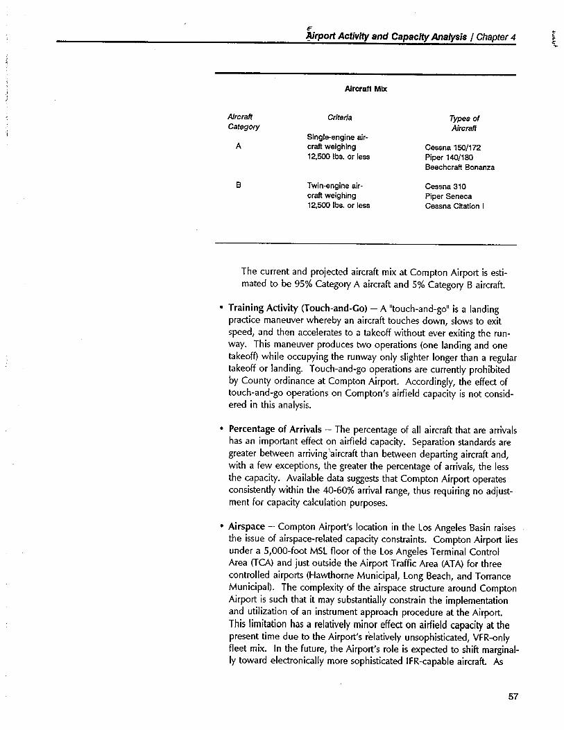
€
Nrport Activit and Capacit Analysis / Chapter 4~t
Aircraft Mix
AircrafCategory
Criteria Types ofAircraft
ASingle-engine air-craft weighing12,50 Ibs. or less
Cessna 150/172Piper 140/180Beechcraft Bonanza
B Twin-engine air-craft weighing12,50 Ibs. or less
Cessna 310
Piper SenecaCessna Citation i
The current and projected aircraft mix at Compton Airport is esti-mated to be 95% Category A aircraft and 5% Category B aircraft.
· Training Activity (Touch-and-Go) - A "touch-and-go" is a landing
practice maneuver whereby an aircraft touches down, slows to exitspeed, and then accelerates toa takeoff without ever exiting the run-way. This maneuver produces two operations (one landing and onetakeoff while occupying the runway only slighter longer than a regulartakeoff or landing. T ouch-and-go operations are currently prohibitedby County ordinance at Compton Airport. Accordingly, the effect oftouch-and-go operations on Compton's airfield capacity is not consid-ered in this analysis.
· Percentage of Arrivals - The percentage of all aircraft that are arrivalshas an importnt effect on airfield capacity. Separation standards aregreater between arriving aircraft than between departing aircraft and,with a few exceptions, the greater the percentage of arrivals, the lessthe capacity. Available data suggests that Compton Airport operatesconsistently within the 40-60% arrival range, thus requiring no adjust-ment for capacity calculation purposes.
· Airspace - Compton Airport's location in the Los Angeles Basin raisesthe issue of airspace-related capacity constraints. Compton Airport liesunder a 5,000-foot MSL floor of the Los Angeles Terminal ControlArea (TCA) and just outside the Airport Traffic Area (AT A) for threecontrolled airport (Hawthorne Municipal, Long Beach, and TorranceMunicipal). The complexity of the airspace structure around ComptonAirport is such that it may substantially constrain the implementationand utilization of an instrument approach procedure at the Airport.This limitation has a relatively minor effect on airfield capacity at thepresent time due to the Airport's relatively unsophisticated, VFR-onlyfleet mix. In the future, the Airport's role is expected to shift marginal-
ly toward electronically more sophisticated IFR-capable aircraft. As
57
Airport Activity and Capacity Analysis / Chapter 4iF~ì,.
c
!r_
this occurs, instrument approach procedure constraints wil reduce theAirport's Annual Service Volume on the order of 3% to 5%.
Annual Utilization
The second part of the Annual Service Volume equation concerns AnnualUtilization (AU), a factor that expresses traffic peaking characteristics at anairport. To illustrate, an Hourly Capacity of 100 might otherwise implyan Annual Capacity of 876,000 operations (100 hourly operations times8J60 hours in a year). This, of course, would not be the case, as thereare hours of the day and days of the year when aircraft do not operate.Furthermore, even during the hours when aircraft operate, the demandcan be expected to fluctuate. The Annual Utilization factor is itself con-structed of two variables that reflect airport activity patterns:
AU = Daily Ratio x Hourly Ratio = Annual MovementsPeak Hour Movements
Simply stated, the Daily Ratio is a value that expresses the number ofdays (each equivalent to the peak day) it would take to represent a year'straffic. The Hourly Ratio is a value that expresses the number of hours(each equivalent to the peak hour) it would take to represent a peakday's traffiC. The more even the traffic flow is, the higher the AnnualUtilization will be.
AIRFIELD CAPACITY CONCLUSIONS
Weighted Hourly Capacity
Based on the above mentioned assumptions and the methodology setforth in FAA Advisory Circular 150/5060-5, the Weighted Hourly Capacityfor Compton Airport, with its existing parallel runway/exit configuration, is145 operations per hour. A maximum effort to improve the exit con-figuration (two additional exits and widened fillet radii for all exits) forcapacity purposes would increase the Weighted Hourly Capacity to ap-proximately 155 operations per hour.
The FAA provides no explicit methodology for assessing the impact of thecontinuous "drift-off taxiway concept in terms of increased runway capac-ity. Based upon discussions with air traffic controllers experienced withthe "drift-off' configuration and an abbreviated queuing analysis, it is theconsultant's judgement that a Weighted Hourly Capacity of 125 opera-tion's per hour could be achieved with a continuous "drift-off' taxiwaysystem serving a single runway.
58
~rport Activit and Capacit Analysis / Chapter 4~
l
Annual Utilization
Existing
Available peaking data at Compton Airport suggests a current AnnualUtilization factor of 2,030 based upon a Daily Ratio of 325 and an Hour-ly Ratio of 6.25.
Future
As peak periods become congested, it is expected that an increasedpercentage of operations will occur during off-peak periods. This willproduce an increase in Annual Utilization at the Airport and thereforeincrease Annual Capacity. There is some practical limit to the extent thatoperations can be expected to naturally move to the off-peak periods.Theoretically, it is possible to reduce peaking even further through opera-tional policies and increased tenant awareness. The effect of such anapproach was also evaluated.
Summary
As can be inferred from the number of variables and assumptions de-scribed in the preceding text, there is no single value which can be usedto completely describe the various capacities of Compton Airport. Theoperational capacity of the Airport depends primarily on the ultimaterunway/exit configuration selected and on the degree to which operationscan be shifted to off-peak periods.
Table 7 indicates the range of capacity values for the different planningassumptions. This data indicates that the current airfield capacity isaround 294,000 annual operations, with a peak-hour capacity of 145operations. The future airfield capacity ranges between approximately193,000 annual operations (single runway with no exit improvements anda natural shift to off-peak periods) to over 400,000 annual operations(parallel runways with angled exit enhancements and a managed shift tooff-peak periods) with a peak-hour capacity of 95-155 operations.
BUILDING AREA CAPACITY
Existing
Compton Airport consists of some 77 acres, of which approximately 47acres are devoted to the existing runway/taiway system and 30 acres arewithin the existing building area.
59
Airport Activity and Capacit Analysis / Chapter 4if..~ ~
Virtually all of the airport land area is developed. Approximately 90% (27acres) of the 30 acres within the existing building area is presently uti-lized. Preliminary analysis indicates that there is the potential of some400 or more aircraft parking spaces within the existing building area,continuing the existing general configuration and density. These figuresequate to an average development density of 13.3 aircraft spaces perbuilding area acre. Findings from numerous other general aviation air-port reveal an average development density of 8.0 total (based andtransient) aircraft spaces per acre, with nearly all airport falling between7.0 and 9.0. Compton Airport is, therefore, relatively densely utilized inthis regard. This high-density level is the result of closely-spaced aircraftparking positions and the Airport's lack of adherence with current FAAairport design standards.
Future
Complete utilization of the Airport's entire available building area will berequired if the Airport is to accommodate the maximum number of basedand transient aircraft. Three significant design factors influence the ulti-mate building area capacity of Compton Airport. These factors are iden-tified below and are analyzed in greater detail in the following chapters.
Parallel Runway System versus a Single Runway
The Airport's present closely-spaced parallel runway configuration is veryinefficient from an airport land use perspective, in that its excessive landarea requirement is not commensurate with its modest added runwaycapacity. A portion of the land area devoted to the parallel runwaysystem might better be utilized to achieve airport dimensional compliancewith FAA design standards and to accommodate additional based andtransient aircraft.
Acquisition of Additional Airport Property
The scope of this master plan study included the investigation of possibleland acquisition for two purposes: (1) Runway Protection Zone and/or (2)building area expansion. It should be noted that the acquisition of adja-cent private propert for the purposes of building area expansion will be
difficult to justify on a benefit/cost basis alone. The imputed value ofland used for aircraft storage purposes is typically far less than the landvalues associated with other urban uses.
FM Design Standards
The Airport, as presently configured, does not meet many significant FAAdesign standards. If practical, any major development or reconfigurationof the Airport should be accomplished in a manner which meets or
60
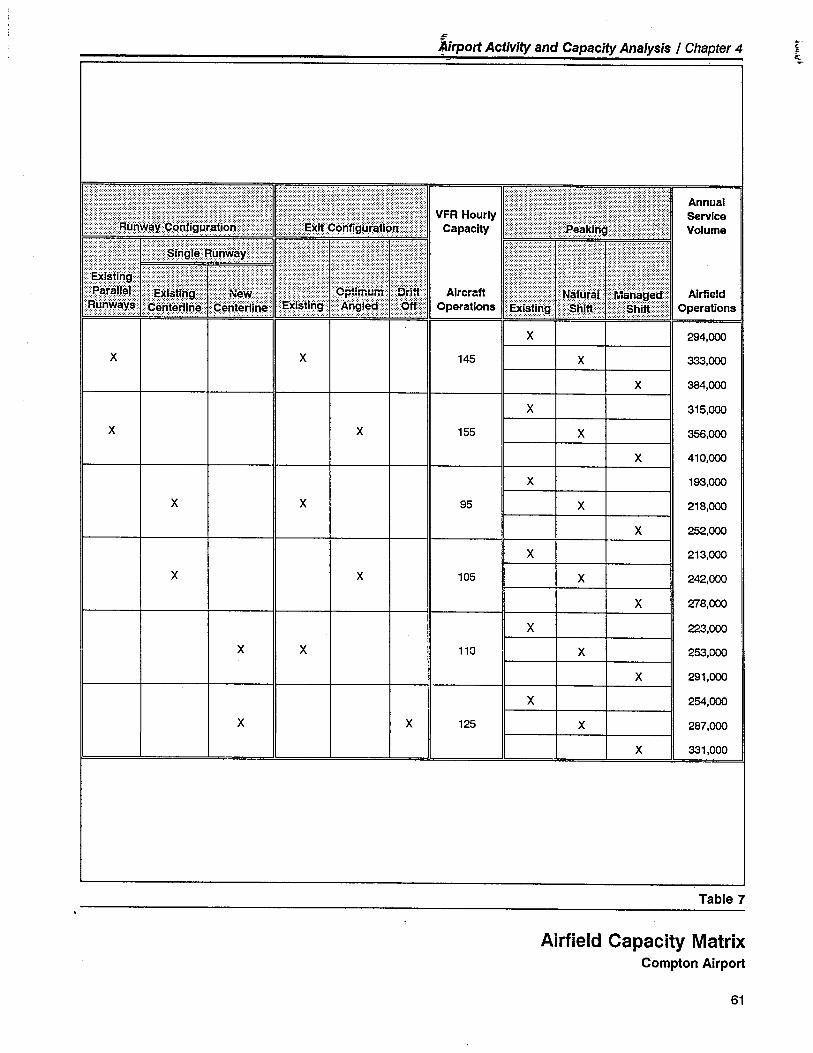
iF~irport Activit and Capacity Analysis I Chapter 4
" ~c
Æ
AnnualServiceVolume
.............................................,_......................................................................................................................................................................................................................................
::::::ar~tmij:::: """""",:",:""""""""""""""""~:r:R#ran:erm t¡r/~l~nnij~r¡~ ....
Ran))~Y~::Ç~W:!rlJhlf
x x 95
AIrfeldOperations
X 294,00
X 33,00
X 38,00X 315,00
X 35,00X 410,00
X 193,00
X 218,00
X 252,00
X 213,00
X 242,00
X 278,00
X 223,00
X 253,00
X 291,00
X 254,00
X 287,00
X 331,00
X X 145
X X 155
X X 105
X X 110
X X 125
Table 7
Airfield Capacity MatrixCompton Airport
61
AirpûrÎ Activitý and Capacity Analysis I Chapter 4~.~~-- .
l.
exceeds FAA design standards. This is particularly importnt as airportactivity and complexity increases in the future.
BALANCED CAPACITY
A relatively direct relationship exists between airfield capacity and build-ing area capacity. The key link is the aircraft utilization rate, which ismeasured in terms of the average number of operations per based air-craft. Table 8 examines this relationship at Compton Airport. It con-cludes that full development of the acreage currently available for build-ing area use would result in an operational level well within the airfield'sexisting capacity. This assumes that the existing parallel runway configu-ration is retained. However, this scenario does not provide sufficientbuilding area to accommodate anticipated based aircraft demand.
The Master Plan projects a demand for up to 500 based aircraft at theAirport by the year 2010. Aircraft activity will generate an estimated156,000 annual operations in the year 2010. The capacities of the air-field and building areas will be adequate to accommodate this projecteddemand in a balanced manner, only if the existing parallel runway systemis replaced by a single runway configuration. This capacity relationship isbalanced, in that the ultimate aircraft basing capacity of the Airport willgenerate slightly less annual operations than the Airport's airfield capacity.
Due to the nature of aircraft operations at Compton Airport, environmen-tal capacity is not expected to be a significant constraint on airport devel-opment.
62
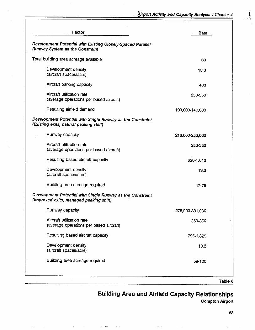
iF..rport Activity and Capacity Analysis I Chapter 4
ccf~," 'T
Factor Data
Development Potential with Existing Closely-Spaced ParallelRunway System as the Constraint
Total building area acreage available 30
Development densit
(aircraft spaces/acre)13.3
Aircraft parking capacity 400
Aircraft utilization rate(average operations per based aircraft)
250-350
Resulting airfield demand 100,000-140,000
Development Potential with Single Runway as the Constraint(Existing exits, natural peaking shift)
Runway capacit 218,000-253,000
Aircraft utilization rate(average operations per based aircraft)
250-350
Resulting based aircraft capacity 620-1,010
Development densit
(aircraft spaces/acre)13.3
Building area acreage required 47-76
Development Potential with Single Runway as the Constraint(Improved exits, managed peaking shift)
Runway capacity 278,000-331,000
Aircraft utilzation rate
(average operations per based aircraft)250-350
Resulting based aircraft capacity 795-1,325
Development density(aircraft spaces/acre)
13.3
Building area acreage required 59-1 00
Table 8
Building Area and Airfield Capacity RelationshipsCompton Airport
63

__.__u___ __.__
~'.'L~' ;J-.r','_.
.!-._-¡::..~-. i ","'~~~~'-:': :-~:;-:/ '. ',.' ~'-,:..':r-: ~:~/~. . ~'",;-..~d_'-..".._"-. ~-'-";~'~~~'.:-'~-:-:.''':'~~''''''''''~-_-:-~-'~''6'~~'~~~~--___"" ____
- ~-- __ _______~___ ._u
".::'r...-:v:.,-.,~.o'-=~... .;'~_..,.-._,.,'-'-.'::':~~_
64
~Airfield Design:
\
In this chapter, the technical
factors and requirements whichinfluence the design of the air-field system are first identified.Various alternative airfield con-figurations are then reviewed
and a recommended airfielddevelopment plan presented.The airfield system includes therunways and taxiways and relat-ed approach and landing aids.
5
Airfield Design
DESIGN FACTORS
As identified in the previous analyses of aviation activity and airport role,the present and future operational role for Compton Airport is to serve asa public-use airport capable of accommodating based and transient,single-engine and light twin-engine, fixed-wing and rotary-wing, generalaviation aircraft. Such aircraft are primarily used for personal, recreation-al, and business purposes and represent the large majority of aircraftpresently using the Airport.
In consideration of this operational role, four key design factors havebeen identified which largely shape the future development and opera-tion of the Airport. These design factors are:
· Provide adequate airfield facilities and services consistent with theAirport's role, user demand, and available resources - both financialand physicaL.
· Maximize the effective utilization of available airport propert foraviation support activities and aircraft storage.
· Wherever feasible, bring the Airport into compliance with applicableFAA airport design standards and recommendations.
· Ensure that acceptable levels of airport operational safety and land usecompatibility are maintained through appropriate approach zone pro-tection and control.
In addition to these four key design factors, a number of significant air-field design issues and opportunities have been identified which requireconsideration in the formulation of the Master Plan. Figure 11 graphicallysummarizes these importnt design considerations. The remainder of thischapter addresses these airfield design factors, issues, and opportunities.
65
Airfield Design I Chapter 5
The FAA has established stan-dards for the design and con-
struction of public-use, general
aviation airports. These stan-
dards have been developed toassist airport sponsors and oper-ators in the appropriate plan-
ning, development, operation,and maintenance of aviationfacilties.
66
AIRPORT DESIGN STANDARDS
It should be noted that early in the preparation of this Master Plan, theFAA revised its airport design standards. Although most of the establishedguidelines remain the same, some are now considered to be "recommen-dations" rather than "standards." Also, certin previous criteria are givengreater emphasis, some new criteria are added, and the terminology forothers has been changed. These updated standards and recommenda-tions are documented in Advisory Circular 150/5300-13 Airport Design.The Compton Airport Master Plan has bee'1 prepared in accordance withthese new FAA design standards and recommendations.
Airport Reference Code
Development of a long-range plan for Compton Airport's runway andtaxiway system first requires that the appropriate runway classification andassociated design standards be determined. In this regard, the FAA hasestablished a coding system, the Airport Reference Code (ARC), to relateairport design criteria to the operational and physical characteristics of theaircraft intended to operate at the Airport.
The code has two components relating to the Airport's design aircraft.The first component, depicted by a letter (A-E), is the Aircraft ApproachCategory and relates to aircraft approach speed - an operational charac-teristic. The second component, depicted by a Roman numeral (I-VI), isthe Airplane Design Group and relates to airplane wingspan - a physicalcharacteristic. Generally, the aircraft approach speed component appliesto runways and runway-related facilities. The airplane wingspan compo-nent primarily relates to separation criteria involving taxiways and taxi-lanes. .Airport design first requires selecting the appropriate Airport ReferenceCode and then applying the associated airport design criteria. In addi-tion, the type of instrument approach and airspace operating environmentare considered in the determination of the applicable airport design stan-dards.
At Compton Airport, these design factors are characterized as follows:
· Aircraft Types - At the present time, the Airport is predominantly
used by single-engine and light twin-engine aircraft that fall withinAircraft Approach Categories A and B (approach speeds less than 91knots and 121 knots, respectively) and Airplane Design Group I (air-planes with wingspans of less than 49 feet). Furthermore, the largemajority of these aircraft weigh 12,500 pounds or less (maximumcertified takeoff weight) and are classified for airport design purposesby the FAA as "Small Airplanes." The anticipated future usage of theAirport also falls within these design categories.
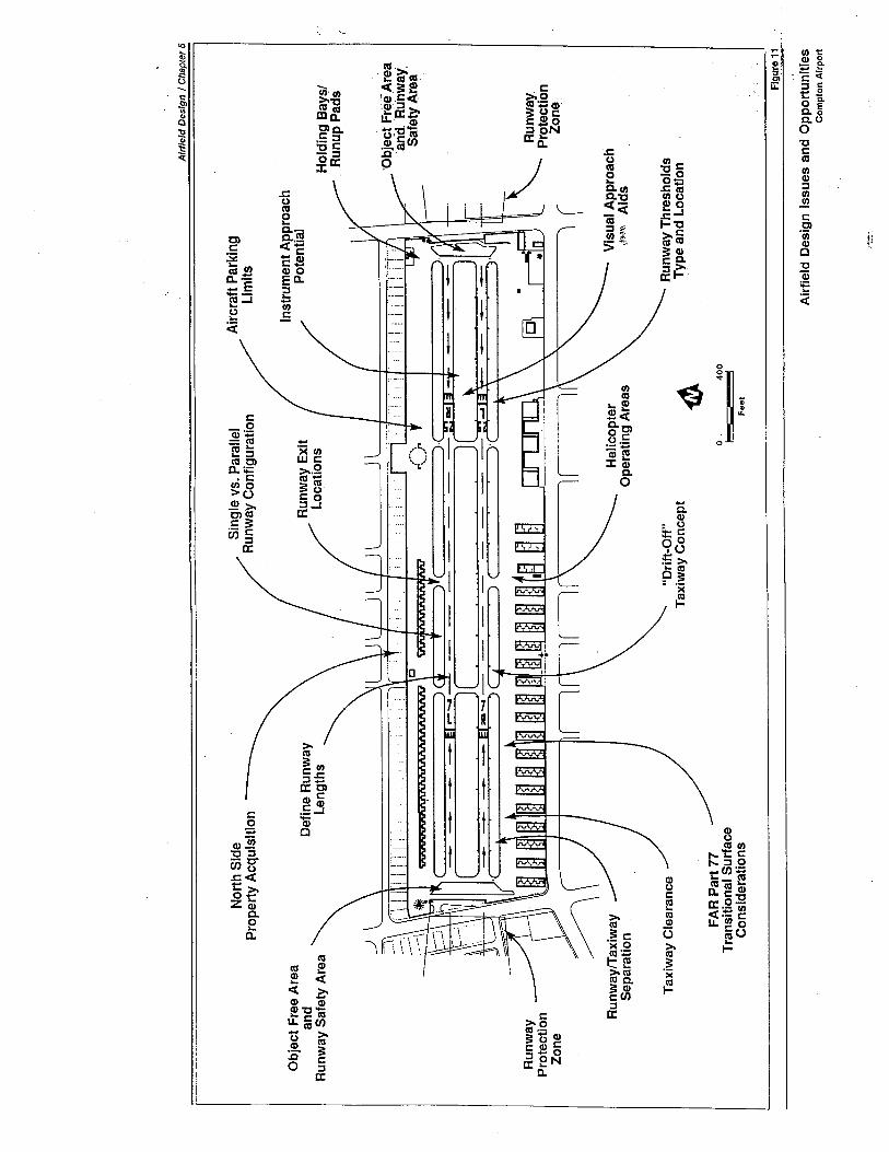
Alr
flet
d D
esig
n I
Cha
pter
5
Nor
th S
ide
Property Acquisition
Sin
gle
VS
. Par
alle
lR
unw
ay C
onfi
gura
tion
Air
craf
t Par
king
Lim
its
Obj
ect F
ree
Are
aan
dR
unw
ay S
afet
y A
rea
Def
ine
Run
way
Len
gths
Run
way
Exi
tL
ocat
ions
Inst
rum
ent A
ppro
ach
Pote
ntia
l
Hol
ding
Bay
s/. R
unup
Pad
s
¡"1
i ¡'O
bjec
t Fre
e,A
rea
ana.
R
u'nw
ayS
afet
y A
rea
'
) )
c),
Run
way
Prot
ectio
nZ
one
~ r
Run
way
Prot
ectio
nZ
one:
Run
way
fTax
iway
Sepa
ratio
nH
elic
opte
rO
pera
ting
Are
asV
isua
l App
roac
hiW
V, A
Ids
Taxiway Clearance
"Dri
ft-O
ff"
Tax
iway
Con
cept
ftR
unw
ay T
hres
hold
sT
ype
and
Loca
tion
FA
R P
art 7
7T
rans
ition
al S
unac
eC
onsi
dera
tions
o ' i-
400 I
Feet
Flgun" 1 ~_. .
Airf
ield
Des
ign
Issu
es a
nd O
ppor
tuni
tes
Com
pI
on A
irpor
t
......
.
Airfield Design / Chapter 5
· Instrument Approach Potential - Compton Airport does not present-ly offer instrument approach capability. Due to airspace complexityand airfield design considerations, it may be difficult to establish aviable instrument approach procedure, either precision or nonpre-cis ion, that fully meets FAA siting requirements and adequately servesthe Airport. However, the option of establishing a non precision instru-ment approach procedure (e.g., NDB, VOR, LOC, lDA, SDF, lORAN-C, etc.) at Compton Airport should be preserved. Existing and futureobstructions to air navigation, both on Airport propert and in thevicinity of the Airport, may preclude the attinment of "straight-in"instrument landing minimums at Compton Airport. However, theAirport may still qualify for a non precision instrument approach thatterminates in a "visual" (i.e., "circling") maneuver to a landing. A for-mal FAA aeronautical study will be required to determine the appro-priate type of instrument approach and the approach/landing mini-mums. For airport master planning and design purposes, a "visual"approach classification has been assumed. Due to prevailing windand airspace utilization considerations, it is anticipated that any suchinstrument approach procedure would be oriented to principally servethe Runway 25 system.
Table 9 compares the FAA design standards for an Airport ReferenceCode B-1 (Small Airplanes/ Visual) airport with Compton Airport's existingdimensions. As can be seen, there is little correlation between the Air-port's existing dimensions and current Airport Reference Code B-1 (SmallAirplanes/ Visual) airport design standards. This is not unusual for anolder, well-established airport such as Compton. FAA design standardshave evolved over the years, resulting in this apparent present lack ofdimensional correlation.
Critical Aircraft
Under most circumstances, an airport should be designed to the highestset of standards needed to accommodate the critical aircraft likely to usethe facility on a regular basis in the future. This objective must be bal-anced against the costs - both in dollars and in the loss of opportunity tobetter utilize available land - of implementing a higher set of standards.The critical aircraft anticipated to use Compton Airport within the 20-yearplanning period are encompassed within Aircraft Approach Categories Aand B, and Airplane Design Group I (Small AirplanesNisual). Such criti-cal aircraft are defined as having a maximum certificated takeoff weight of12,500 pounds or less, a wingspan of less than 49 feet, and an approachspeed of less than 121 knots. Examples of such aircraft include: Cessna150, Beechcraft Bonanza, Piper Aerostar, Rockwell 690, Beechcraft KingAir B100, and the Cessna Citation i - a small corporate jet.
The FAA classifies an airport that is designed, constructed, and maintainedto serve airplanes in Aircraft Approach Categories A and B as a Utilityairport. More specifically, a Basic Utility - Stage II airport. In addition,
67
--...~..~.:~.~..~..~~. '_";~~,:,:~-:~.~",, ._'0.-'___--0... .',~.'....
Airfield Design I Chapter 5
-_._-~_.:..__:......~~~~~:~~.. ---.--~--~~--~,,~....;."...._.:--=
For the purposes of this discus-sion, the use of the term "run-
way" refers to either the existingparallel runways system or asingle runway.
68
due to the extensive current and projected future use of helicopters at theAirport, it is appropriate that a critical helicopter be identified for designpurposes. In this regard, the Bell 206L "Long Ranget', with a rotor diame-ter of 37 feet and a maximum takeoff weight of 4,150 pounds, is suggest-ed as the critical helicopter for Compton Airport design purposes.
Given these factors, it is recommended that Compton Airport be designedin general accordance with Airport Reference Code B-1 (Small Air-planesNisual) standards. Specific implications of this recommendationare discussed in the following sections.
RUNWAY CONFIGURATION DESIGNREQUIREMENTS
The most significant airfield design issue currently facing Compton Airportis the question of whether to maintain the operational viability of the twoexisting closely-spaced parallel runways, or convert the airfield to a singlerunway configuration. Factors to be considered in this analysis include:
· Capacity of the respective runway/taxiway systems and associated
building areas to accommodate future aeronautical demand - bothaircraft operations and based aircraft.
· Capability of the various runway/taxiway configurations to conformwith FAA design standards and recommendations.
· Costs (both capital and maintenance) associated with maintaining twoparallel runways versus the costs of converting to a single runwayconfigu ration.
· Safety and environmental considerations.
· Operational considerations such as desirability of having a secondaryrunway in reserve to facilitate primary runway closure.
· Availability of off-airport land area for airport expansion purposes -particularly the strip of residentially developed land bordering theAirport's north side.
Existing Parallel Runways Configuration
The distance between the existing parallel runways centerlines is 200 feet.At this distance, aircraft operations on one runway are highly interrelated'with aircraft operations on the other runway. Aircraft cannot safelyoperate on both runways simultaneously or independently. The FAA
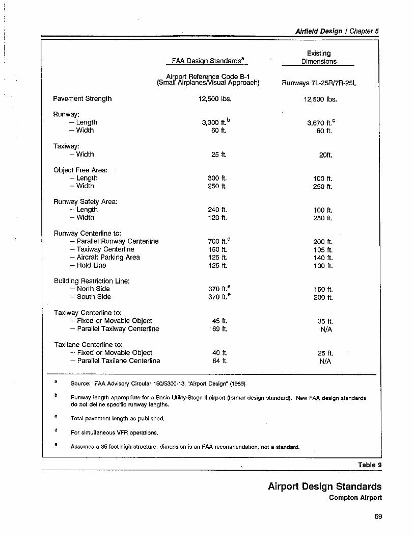
Airfield Design / Chapter 5
FAA Desiççn Standardsa
Airport Reference Code B-1(Small AirplanesNisual Approach)
ExistingDimensions
Runways 7L-25R/7R-25L
Pavement Strength 12,500 Ibs. 12,500 Ibs.
Runway:- Length
- Width
b3,300 ft.60 ft.
3,670 ft. C60 ft.
Taxiway:- Width 25 ft. 20ft.
Object Free Area:
- Length
- Width
300 ft.250 ft.
1 00 ft.250 ft.
Runway Safety Area:- Length
- Width
240 ft.120 ft.
1 00 ft.250 ft.
Runway Centerline to:- Parallel Runway Centerline- Taxiway Centerline
- Aircraft Parking Area
- Hold Line
700 ft. d150 ft.125 ft.125 ft.
200 ft.1 05 ft.140 ft.1 00 ft.
Building Restriction Line:
- North Side
- South Side
370 ft. e370 ft. e
150 ft.200 ft.
Taxiway Centerline to:- Fixed or Movable Object
- Parallel Taxiway Centerline
45 ft.~ 69 ft.
35 ft.N/A
Taxilane Centerline to:- Fixed or Movable Object
- Parallel Taxilane Centerline
40 ft.64 ft.
25 ft.N/A
a Source: FAA Advisory Circular 150/53-13, "Airport Design. (1989)
b Runway length appropriate for a Basic Utilty-Stage II airport (former design standard). New FAA design standardsdo not define specific runway lengths.
c Total pavement length as published.
d For simultaneous VFR operations.
e Assumes a 35-foot-high structure; dimension is an FAA recommendation, not a standard.
Table 9
Airport Design StandardsCompton Airport
69
Airfield Design / Chapter 5
recommends a parallel runway centerline to parallel runway centerlineminimum distance of 700 feet for simultaneous operations in visual mete-orological conditions.
Single Runway Configuration
If a single runway configuration were to be established at Compton Air-port, FAA design standards, as identified in Table 9, would apply. Poten-tially, the single runway would be served on both sides by parallel taxi-ways. The minimum recommended runway centerline to parallel taxiwaycenterline dimension is 150 feet. The principal alternative single runwayairfield configurations include:
· Retain Runway 7R-25L and close Runway 7L-25R.
· Retain Runway 7L-2SR and close Runway 7R-25L.
· Construct a new single Runway 7-25 and close the existing Runways7R-25L and 7L-25R.
An analysis of the existing parallel runways configuration versus the vari-ous single runway configuration alternatives is presented in the "RunwayConfiguration Alternatives" section of this chapter.
RUNWAY ORIENTATION DESIGN REQUIREMENTS
Wind direction is a primary design factor influencing runway orientation.Additional runway orientation design factors include terrain, area airspaceinteraction, existing airport configuration, and adjacent off-airport landdevelopment.
Ideally, a runway should be aligned with the prevailing wind. In somecases, more than one runway may be necessary to provide the desiredlevel of wind coverage - 95% coverage at 13 knots (15 m.p.h.) crosswindcomponent. This level of wind coverage takes into account various fac-tors influencing aircraft operations, as well as the economics of providingthe desired coverage. When a runway cannot provide at least 95% windcoverage, either widening of the primary runway or providing a crosswindrunway should be considered.
There is no on-site recorded wind data available for Compton Airport.However, wind data is available for a nearby location - 21718 SouthAlameda Street. For planning purposes, this nearby wind data, presentedin the form of a wind rose, can be considered to be applicable to Comp-ton Airport. The wind rose is presented in graphic form on the AirportLayout Plan (see Chapter 2 - Figure 1).
70
Airfield Design I Chapter 5
The airfield design implications associated with this level of wind cover-age are discussed in the "Runway Orientation Alternatives" section of thischapter.
RUNWAY LONGITUDINAL DESIGN REQUIREMENTS
The longitudinal requirements of a runway's design involve more than justthe runway's length. Other design components to be considered include:Object Free Areas, Runway Safety Areas, FAR Part 77 approach surfaces,Runway Protection Zones (formerly known as "Clear Zones"), and landingthreshold locations.
Runway Length
Within the recent past, FAA design standards identified recommendedlengths for runways intended to serve small airplanes with approachspeeds of 50 knots or more. For the types of aircraft Compton Airport isnow serving and is anticipated to be serving in the future, these formerFAA design standards indicated a runway length of 3,000 feet (at Comp-ton Airport's 82°F. mean daily maximum temperature and 97-foot airportelevation). This runway length corresponds with the FAA's Basic Utility-Stage II airport design classification.
The recently revised FAA design standards do not recommend specificrunway lengths. Rather, the FAA suggests that the determination of theappropriate runway length be based upon a site and user-specific assess-ment of airplane operational characteristics. The Airport's existing pub-lished runway length of 3,670 feet exceeds the requirements of virtuallyall airplanes now operating at the Airport or anticipated to regularly oper-ate there in the future. However, the existing runway length does notprovide for Object Free Areas and Runway Safety Areas that fully meetscurrent FAA design standards. If necessary, the runway could be short-ened a small amount without seriously affecting the operating capabilitiesof the airplanes expected to use the Airport. Such shortening of therunway may be required to adequately provide for Object Free Area andRunway Safety Area requirements, and approach slope clearances.
71
Airfield Design I Chapter 5
':;:.~:'.'~,-_';_,__._'.'...;
An Object Free Area is a two-dimensional ground area sur-rounding the runway end. TheObject Free Area clearing stan-dard precludes parked airplanesand objects, except objects
whose location is fixed by anaeronautical function. This des-
ignated area is newly defined inthe revised FAA airport designstandards.
A Runway Safety Area is acleared, drained, graded, andpreferably turfed area symmetri-cally located about the runwaywhich, under normal conditions,is capable of supporting aircraftrescue and fire-fighting equip-ment and of accommodating theoccasional passage of aircraftwithout causing major damageto the aircraft. The area must befree of objects, except ones
whose function requires theirlocation in the Runway SafetyArea, in which case they mustbe installed on frangible sup-ports.
72
Object Free Areas
.None of the four runway ends is currently configured with an Object FreeArea that fully satisfies FAA design standards. The Object Free Areashould extend a minimum of 300 feet beyond the end of the runwaypavement at a width of 250 feet. This area should be under the directcontrol of the Airport.
At the approach end of Runways 7l and 7R, the existing runway pave-ment comes within 70 feet of the 6-foot-high chain-link fence parallelingthe west side interior airport access road - 230 feet less than the speci-fied design stançlard.
At the approach end of Runways 25l and 25R, the 6-foot high chain-linkfence paralleling the east side interior airport access road is located ap-proximately 50 feet from the physical end of the existing runway pave-ment - 250 feet less than the specified design standard.
In addition, interior airport access roads, cinder block walls, public streets,power lines, light poles, trees, and structures are located within the cur-rent Object Free Areas of all runways.
Runway Safety Areas
None of the four runway ends currently has a Runway Safety Area whichcomplies with FAA design standards. The Runway Safety Areas shouldextend a minimum of 240 feet beyond the end of the runway pavementat a width of 120 feet.
The chain-link fences noted above are located approximately 50-70 feetfrom the end of the runways' pavement - 170-190 feet less than thespecified design standard. In addition, airport access roads, cinder blockwalls, public streets, power lines, light poles, trees, and structures arelocated within the current Runway Safety Areas of all runways.
FAR Part 77 Approach Surfaces
For a runway expected to serve only small airplanes (i.e., 12,500 poundsor less) in visual conditions, FAA design standards and Federal AviationRegulations specify a trapezoidal approach surface which is 5,000 feetlong, 250 feet inner width, and 1,250 feet outer width. If the runway isexpected to serve only small airplanes with non precision instrumentapproach capability (visibility minimums greater than 3/4-mile), the ap-proach surface dimensions become 5,000 feet long, 500 feet inner width,and 2,000 feet outer width. The approach surface begins on the run-way's primary surface, 200 feet from the end of the runway pavement,
Airfield Design / Chapter 5
The FAA defines a Runway Pro-tection Zone as a trapezoidal
area at ground level, beyond therunway end, under the control ofthe airport authorities, for thepurpose of protecting the safetyof approaches and keeping thearea clear of the congregation ofpeople. The Runway ProtectionZone begins at the end of eachprimary surface and is centeredupon the extended runway cen-terline. The term "Runway Pro-tection Zone" has replaced theformerly used term "Clear Zone."
and slopes upwards at a ratio of 20:1. Ideally, no object should pene-trate the approach surfaces or their contiguous 7:1 slope transitionalsurfaces.
In the airfield's present configuration, Central Avenue, with its cinderblock wall, lies just inside the Runway 7L-25R/7R-25L system primarysurface. In addition to the road and wall, there are several more obstruc-
tions in the Runways 7L and 7R primary and approach surfaces, such as achain link fence, internal airport access road, power lines, street lightpoles, trees, and structures. A pole-mounted tennis court light (elevation137:t feet MSL or 40:t feet above the runway elevation) located at theapproach end of the primary surface is the controlling obstruction withinthe Runways 7U7R approach surface.
Similarly, Wilmington Avenue, a cinder block wall, chain-link fence,internal airport access road, street light poles, trees and structures areobstructions within the Runways 25L and 25R primary and approachsurfaces. The controlling obstruction within the Runways 25U25R ap-proach surface is a tree (elevation 115:t feet MSL or 18:t feet above therunway elevation) located along the east side of Wilmington Avenue.
Objects determined by the FAA to be obstructions to air navigation mustbe removed or the runway threshold appropriately relocated or displaced.Accordingly, these controlling obstructions are key determinants in estab-lishing the location of the runways' thresholds.
Runway Protection Zones
The FAA recommends that an airport operator have sufficient control, bymeans of outright ownership or avigation easements, over propert lyingwithin Runway Protection Zones to assure the safety of aircraft approach-es and to keep the area clear of congregations of people. Runway Pro-tection Zones are located relative to the runway pavement ends and donot take into account any threshold displacements. The dimensions ofthe Runway Protection Zone applicable to Compton's existing configura-tion (i.e., Small AirplanesNisual) are: 1,000 feet in length, 250 feet innerwidth, and 450 feet outer width. The inner portion of the zone begins atthe end of the primary surface (i.e., 200 feet beyond the end of therunway pavement). For an airport intended to serve small airplanes witha non precision instrument approach (visibility minimums greater than 3/4-mile), the Runway Protection Zone dimensions increase to 1,000 feet inlength, 500 feet inner width, and 800 feet outer width.
Due to the existing closely-spaced parallel runway configuration andresultant overlapping of Runway Protection Zones, the current dimensionsof the Runway Protection Zones serving Runways 7U7R and 25U25R are1,000 feet in length, 450 feet inner width, and 650 feet outer width.
73
Airfield Design / Chapter 5
In the Airport's current configuration, no significant part of any RunwayProtection Zone is located on airport propert, nor does the Airport pres-ently hold any easements over these off-airport areas. It should be notedthat the Clear Zones depicted on Compton Airport's existing AirportLayout Plan (dated August 1966) are incorrectly located with respect tothe runway pavement ends.
Landing Threshold Locations
When structures, trees, poles, roads, or other objects in the approacharea penetrate the overlying approach surface and cannot be eliminated,relocation or displacement of the runway landing threshold may be nec-essary. Relocation of a runway threshold results in a reduction of avail-able runway length. Displacement of a runway threshold, however,
permits some added operational flexibility in terms of defining runwaylength available for takeoff and landing.
As a rule, establishment of displaced thresholds is discouraged. Thepreferred solution is to remove the offending obstruction. Where short-ening of the runway would not significantly affect aircraft operations,relocation of the runway end to eliminate the displaced threshold shouldbe considered.
If the runway threshold is displaced, the minimum amountof displace-ment can be determined by an FAA-defined threshold location planewhich, for a visual or non precision (visibility one mile or greater)approach, begins at the runway threshold and slopes upward at 20:1.Objects can thus penetrate the FAR Part 77 approach surface, but notrequire displacement of the landing threshold. A minimum of 15 feetthreshold location plane clearance is required over public roads such asCentral Avenue and Wilmington Avenue.
It should be emphasized that the threshold locational criteria noted aboveprovides the minimum approach clearance acceptable to the FAA. It isnot necessarily the most desirable or appropriate for all airport. Moretypically, the runway threshold is established on the basis that there areno obstructions penetrating the 20:1 approach surface, as defined inFederal Aviation Regulation Part 77. The greater measure of approachclearance provided by this latter criteria serves to significantly enhancethe safety and utility of aircraft operations - particularly during aircraftlanding operations at night.
At Compton Airport, the Runways 7L and 7R landing thresholds arepresently displaced 895 feet from the runway end of pavement. TheRunways 25L and 25R landing thresholds are presently displaced by 860feet. These existing threshold displacement distances are considerably
greater than that distance required to satisfy minimum FAR Part 77 ob-struction clearance criteria. It appears that the respective locations of the
74
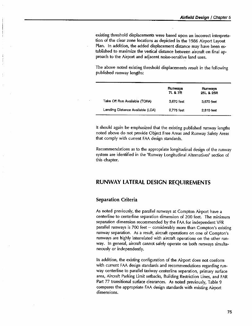
Airlield Design / Chapter 5
existing threshold displacements were based upon an incorrect interpreta-tion of the clear zone locations as depicted in the 1986 Airport layoutPlan. In addition, the added displacement distance may have been es-tablished to maximize the vertical distance between aircraft on final ap-proach to the Airport and adjacent noise-sensitive land uses.
The above noted existing threshold displacements result in the followingpublished runway lengths:
Runways7L & 7R
Runways25L & 25R
Take Of Run Available (TORA) 3,670 feet 3,670 feet
Landing Distance Available (LOA) 2,775 feet 2,810 feet
It should again be emphasized that the existing published runway lengthsnoted above do not provide Object Free Areas and Runway Safety Areas
that comply with current FAA design standards.
Recommendations as to the appropriate longitudinal design of the runwaysystem are identified in the "Runway longitudinal Alternatives" section ofthis chapter.
RUNWAY LATERAL DESIGN REQUIREMENTS
Separation Criteria
As noted previously, the parallel runways at Compton Airport have acenterline to centerline separation dimension of 200 feet. The minimumseparation dimension recommended by the FAA for independent VFRparallel runways is 700 feet - considerably more than Compton's existingrunway separation. As a result, aircraft operations on one of Compton'srunways are highly interrelated with aircraft operations on the other run-way. In general, aircraft cannot safely operate on both runways simulta-neously or independently.
In addition, the existing configuration of the Airport does not conformwith current FAA design standards and recommendations regarding run-way centerline to parallel taxiway centerline separation, primary surfacearea, Aircraft Parking limit setbacks, Building Restriction lines, and FARPart 77 transitional surface clearances. As noted previously, Table 9compares the appropriate FAA design standards with existing Airportdimensions.
75
Airlield Design / Chapter 5
Although Compton Airport has operated for many years with considerablyless runway/taxiway lateral separation than specified by current FAAairport design standards, such continued noncompliance cannot be en-couraged. With the projected future increases in Airport-based aircraftand operations, the necessity of the Airport meeting FAA dimensionalstandards wil become more pronounced.
Land Acquisition Potential
Significant in this analysis of runway design requirements is the questionof the need and practicability of acquiring off-airport land area to permit~irport expansion. Of particular interest in this regard is the rectangularparcel of residentially developed land bordering the Airport's northernpropert line. The potential availability and use of this parcel in largepart influences the analysis of runway configuration alternatives, buildingarea capacity, and overall airport development.
A discussion paper focusing on this specific study issue was prepared aspart of this master planning process. The discussion paper, entitled "Ac-quisition of Additional Land Area," is presented in Appendix D. Thisanalysis concluded that the subject residential land area cannot be feasi-bly acquired by the County at this time. The option of acquiring thesubject land area should, however, be preserved for future consideration.Accordingly, the potential near-term availability of the residential strip ofland bordering the Airport's northern propert line is not considered to bea determining factor in the analysis of airfield configuration alternatives orfuture airport building area development.
If parcels of land become vacant or cleared (due to fire, earthquake, etc.)in the residential strip along the Airport's north side or within the RunwayProtection Zones, the County should consider acquisition of those partic-ular parcels at that time. Such acquisition would be consistent with FAAstandards and requirements, and, therefore, the acquisition would beeligible for FAA grant funding. This option should remain open andaggressively pursued if determined to be politically acceptable to the localcommunity.
A number of other noncontiguous parcels in the vicinity of ComptonAirport were considered as to their possible acquisition value for airportexpansion purposes. It was determined that none of the parcels could befeasibly acquired at this time. However, it is suggested that the Countyremain receptive to contiguous land acquisition opportunities as mayoccur from time to time in the future.
76
Airfield Design / Chapter 5
The following portion of the Mas-ter Plan focuses on alternativedesign concepts and recom-
mended improvements to theairfield system to accommodatefuture demand and to bring theAirport into general compliancewith FAA design standards.
RUNWAY CONFIGURATION ALTERNATIVES
Identification of Alternatives
As noted previously, there are four basic runway configuration alternativesthat deserve special consideration as part of the Master Plan. Thesealternative configurations are:
· Alternative A - Retain existing parallel runway/taxiway system (i.e.,
Runways 7R-25l and 7l-25R).
· Alternative B - Retain Runway 7R-25l and close Runway 7l-25R.
· Alternative C - Retain Runway 7l-25R and close Runway 7R-25L.
· Alternative D - Construct a new single Runway 7-25 and close
Runways 7R-25l and 7l-25R.
The four alternative runway configurations are depicted in Figure 12.Variations of each of these alternative runway configurations were ex-plored as part of the master plan study analysis. However, only thosealternatives that substantially satisfied the stated design requirements areidentified herein.
Analysis of Alternatives
In selecting the desired alternative, the following decision factors wereconsidered. The' selected alternative should:
· Enhance airport operational safety and utility.
· Reflect an appropriate balance between future user demand and re-quired airfield capacity.
· Comply with FAA design standards and recommended dimensionalcriteria.
· Maximize the availability of land area for building development andaircraft parking/storage.
· Be cost-effective and affordable to the user group.
· Reflect an appropriate balance between future user demand and re-quired airfield capacity.
77
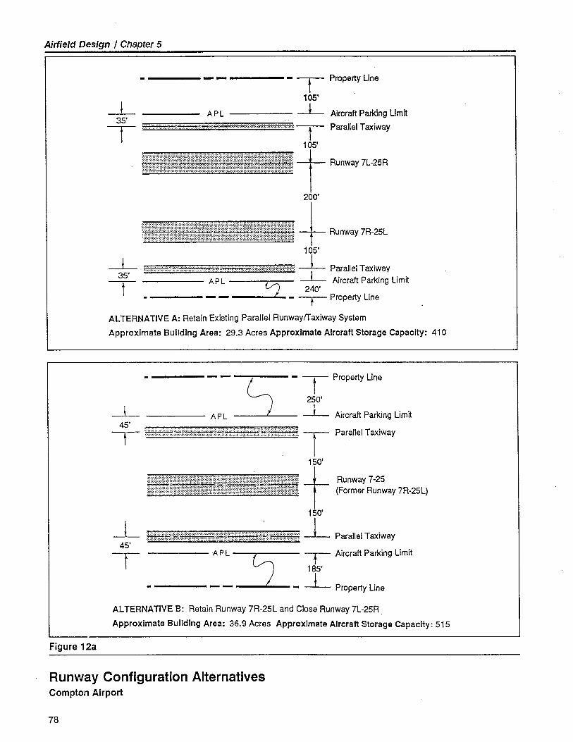
Airfield Design / Chapter 5
--35'T
- T Property Line105'
-- Aircraft Parking Limit
~....,.,.. ................. :::.:::::::::::::...~. ~ :.:.:.:.:.:.:.:: -- Parallel Taxiway
105'
~t Runway7L-25R200'
~ l Runway7R-25L105'
......... . ~ ...........:...,........::. -L Parallel Taxiway
-- Aircraft Parking Limit
V; 240'- -- Property Line
ALTERNATIVE A: Retain Existing Parallel Runwayrraxiway System
Approximate Building Area: 29.3 Acres Approximate Aircraft Storage Capacity: 410
APLi-35'--
.........
APL
- - ~- T Property Line250'
A P L -- Aircraft Parking Limit--45'
--....~....... ~...,~,.".,.,., ..~,~~.,.,~,~,~,.,~,.,~,.,.,~,~,.:.:....,.: .. ..~..~. T Parallel Taxiway
150'
~ t ~~~::;i~~aY7R-25L)150'
'4f\£:::::::::::::::::::::;:::::::::::::::?9\::::::'::::::::::::\i/:\\'er::::::::::::::::::::/:::: -- Parallel Taxiway
.. .""
--45'-- A P L -- -- Aircraft Parking Limit
185'
- - - i- Property Line
ALTERNATIVE B: Retain Runway 7R-25L and Close Runway 7L-25R .
Approximate Building Area: 36.9 Acres Approximate Aircraft Storage Capacity: 515
Figure 12a
Runway Configuration AlternativesCompton Airport
78
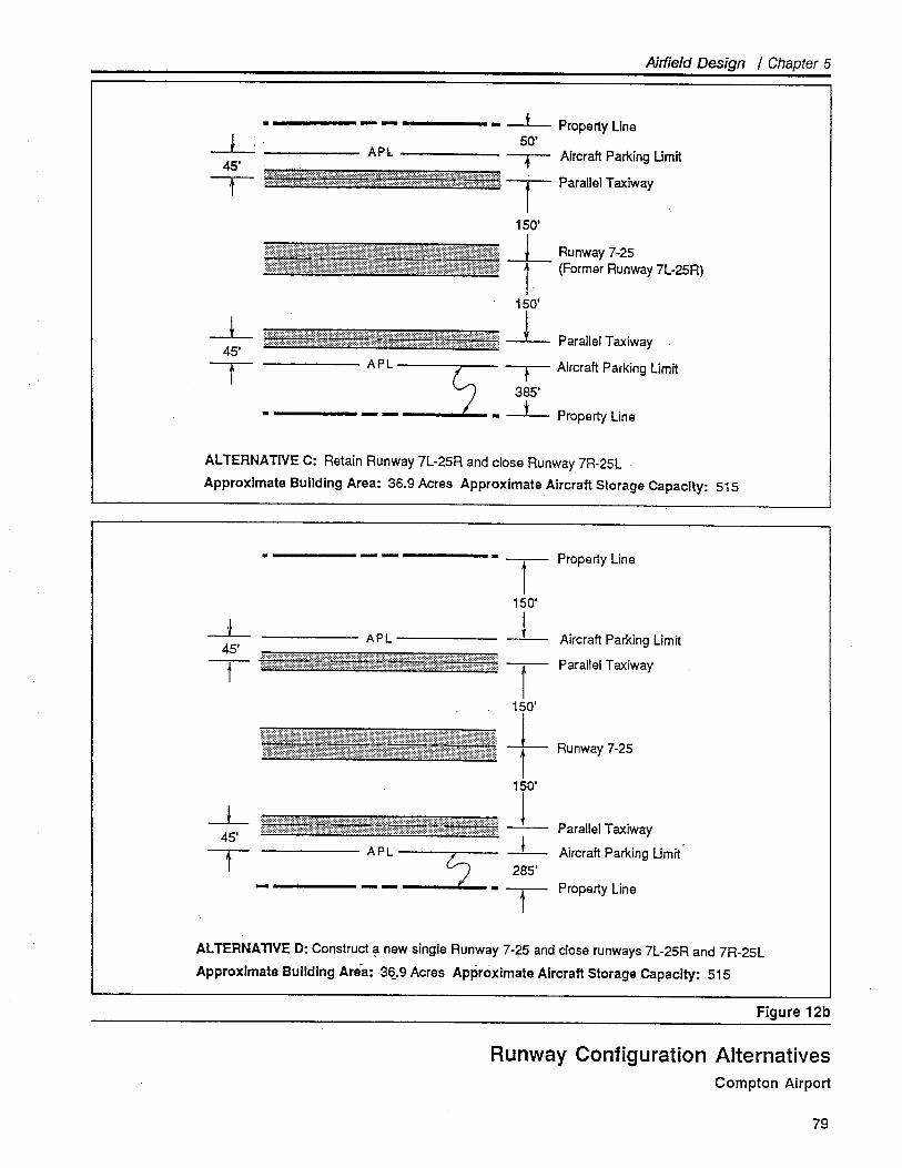
Airfeld Design / Chapter 5
-L45'--
--45'--
- -- Property Line50'.APl -- Aircraft Parking Limit
';:;:::;;(!iii;!)iMt;;;:;;;;';;;;;;;;;:::::)r;;:::iWitit:;i;:;:;:':::::::::;;;:;:;:::;;;)tf:;:;:':::;:;:ri;i? T Parallel Taxiway .
150'
== t ~::~~2n~Y7L.25R)150'
;:;:':":;;:;t;;;;:;::;:::::t'/***¡¡W¡tjiMfBR8Ht:;:';::::::::;:::t:;:::':::::::/; -- Parallel Taxiway
APL -- -- Aircraft Parking Limit
385'
- - - -- Property Line
ALTERNATIVE C: Retain Runway 7L-25R and close Runway 7R-25L
Approximate Building Area: 36.9 Acres Approximate Aircraft Storage Capacity: 515
--45'--
--45'T
Property LineT150'-- Aircraft Parking Limit
Parallel Taxiway
APL
~;~~~t~~t~~~~~;~;~~~~~~~~;~~~;;;jjEtii$~tffr~ri¡t~~~~~~~~;~~;;~~~;~~~~~;~;~g~~~~;~~~~T150'
--1
150'
----285'
Parallel Taxiway
Aircraft Parking Limit
'::",::;;:¡:¡,!:~:;::;,:::':;,~:::::I::':¡:¡'::¡,:~::j::;:~,:':;::',:~¡:::,I:::¡",'.:,,;:j¡::::'j~;,;::;:::I:':::;,'::i'!'",::.j:',¡1'::,:':;;j':!,;:Runway 7-25
~~;~~~~~~;~~;;;~~~;~~;~;¡;;;Ø¡~¡¡~llf/~~~~~~~;~~~~~/~~~~~~;~;¡jt¡i¡¡~;~~~;~;;;;~;;;;;;;~~;;;~;;¡~¡¡¡iI\t\tt~~/~~~t~~~~;~;
APL f¡-T- Property Line
ALTERNATIVE D: Construct ~ new single Runway 7-25 and close runways 7L-25R and 7R-25L
Approximate BuildIng Aréa: 3a.9 Acres Approximate Aircraft Storage Capacity: 515
Figure 12b
Runway Configuration AlternativesCompton Airport
79
Airfield Design / Chapter 5
· Accommodate a "circling" (i.e., visual) non precision instrumentapproach capability.
· Be environmentally acceptable.
· Facilitate the transition between the existing airport configuration andthe ultimate airport configuration.
· Be flexible with respect to the potential role of the Airport beyond the20-'year planning time frame.
An overview of the relative advantages and disadvantages associated witheach of the four alternative runway configurations is presented in Table10.
As was indicated in the Chapter 2 analysis of future aeronautical demand(i.e., based aircraft and operations) versus airfield capacity (i.e., aircraftstorage area and runway/taxiway capacity), Compton Airport is essentially"land poor." Towards the middle of the 20-year planning period, demandfor aircraft storage positions will exceed the available aircraft storagecapacity. Runway/taxiway capacity, either in the Airport's existing parallelrunway configuration or in a single runway configuration, is more thansufficient to accommodate projected operational demand through the 20-year planning period.
As a result, the emphasis on future development of Compton Airportshould be to maximize the accommodation of based aircraft. Due to thelimited airport propert available (77 acres), maximization of the Airport's
based aircraft capacity requires that the relatively space-inefficient parallelrunways configuration be ultimately replaced by a more space-efficientsingle runway configuration. Utilization of the single runway configura-tion enables approximately 100 additional aircraft to be based at theAirport. This number assumes that all available aircraft parking positionsare utilized. The reduction in runway capacity resulting from the shiftfrom a closely-spaced parallel runways configuration to a single runwayconfiguration is minimal and of no significant operational consequence.As noted in Chapter 4, the single runway configuration offers more thanadequate capacity to accommodate the Airport's projected 20-year opera-tional demand.
It should be noted that the ultimate aircraft basing capacities indicated forrunway configuration Alternatives Bf C, and D (see Figure 12) reflect thefollowing FAA dimensional standards:
· 150-foot separation between runway centerline and parallel taxiwaycenterline; and
· 45-foot separation between parallel taxiway centerline and AircraftParking Limit.
80
Airfield Design / Chapter 5
A reduction in these dimensions to match the Airport's existing dimen-sions (i.e., 105 feet and 35 feet, respectively), would enable an additional130 aircraft to be based at the Airport under Alternatives B, C, and D.However, due to the intensity, density, and complexity of future aircraftoperations at Compton Airport, such a reduction in dimensional standardsis not recommended.
Recommended Runway Configuration
Given the design requirements and decision factors noted above, theoptimum future runway configuration is judged to be Alternative C. Theprimary reason for the selection of Alternative C is that this configurationmaximizes the amount of developable area on the terminal/fixed baseoperations side of the runway while meeting FAA dimensional standards.In addition, this alternative offers certin cost efficiencies in the phasingand construction of the runway/parallel taxiway system.
To facilitate the implementation of this single runway configuration, thefollowing development plan is suggested:
· Maintain the existing parallel runways/taxiway configuration until suchtime as:
- Aircraft basing demand approaches currently available space; or
- Significant maintenance or rehabilitation is required on the runwayor runway lighting system.
· In the interim, configure all improvements (hangars, tiedowns, facili-ties, etc.) so as to be consistent with both the present and future air-field configurations.
· When appropriate, reconstruct and light Runway 7L-25R. Close Run-way 7R-25L.
· Initially, utilize the northern portion of the former Runway 7R-25L as aparallel taxiway.
· Relocate tiedowns and T-hangars on the north side of the new Run-way 7-25 so as to comply with the 150-foot runway centerline toparallel taxiway centerline separation and the 45-foot parallel center-line taxiway to Aircraft Parking Limit.
· When required to accommodate based aircraft demand, construct anew south-side parallel taxiway with a runway centerline to paralleltaxiway centerline separation of 150 feet and a parallel taxiway center-line to Aircraft Parking Limit separation of 65 feet.
81
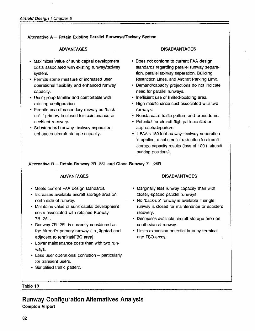
Airfield Design / Chapter 5
Alternative A - Retain Existing Parallel Runways/Taxiway System
ADVANTAGES
· Maximizes value of sunk capital developmentcosts associated with existing runway/taxiwaysystem.
i · Permits some measure of increased user
operational flexibilty and enhanced runwaycapacity.
· User group familar and comfortable withexisting configuration.
· Permits use of secondary runway as "back-
up. if primary is closed for maintenance oraccident recovery.
· Substandard runway-taxiway separationenhances aircraft storage capacity.
DISADVANTAGES
· Does not conform to current FAA designstandards regarding parallel runway separa-tion, parallel taxiway separation, BuildingRestriction Lines, and Aircraft Parking Limit.
· Demand/capacity projections do not indicateneed for parallel runways.
· Inefficient use of limited. building area.· High maintenance cost associated with two
runways.· Nonstandard traffic pattern and procedures.· Potential for aircraft flightpath conflict on
approach/departure.· If FAA's 150-foot runway-taxiway separation
is applied, a substantial reduction in aircraftstorage capacity results (loss of 100+ aircraftparking positions).
Alternative B - Retain Runway 7R-25L and Close Runway 7L-25R
ADVANTAGES
· Meets current FAA design standards.· Increases available aircraft storage area on
north side of runway.· Maintains value of sunk capital development
costs associated with retained Runway7R-25L.
· Runway 7R-25L is currently considered asthe Airport's primary runway (i.e., lighted andadjacent to terminal/FBO area).
· Lower maintenance costs than with two run-ways.
· Less user operational confusion - particularlyfor transient users.
· Simplified traffic pattern.
DISADVANTAGES
· Marginally less runway capacity than withclosely-spaced parallel runways.
· No "back-up" runway is available if singlerunway is closed for maintenance or accidentrecovery .
· Decreases available aircraft storage area onsouth side of runway.
· Limits expansion potential in busy terminaland FBO areas.
Table 10
Runway Configuration Alternatives AnalysisCompton Airport
82
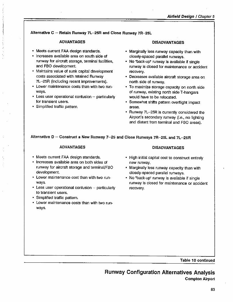
Airfield Design I Chapter 5
j:~
.11i Alternative C - Retain Runway 7L-25R and Close Runway 7R-25L
ADVANTAGES
· Meets current FAA design standards.
· Increases available area on south side ofrunway for aircraft storage, terminal facilties,and FBO development.
· Maintains value of sunk capital developmentcosts associated with retained Runway7L-25R (including recent improvements).
· Lower maintenance costs than with two run-ways.
· Less user operational confusion - particularlyfor transient users.
· Simplified traffic pattern
DISADVANTAGES
· Marginally less runway capacity than withclosely-spaced parallel runways.
· No "back-up" runway is available if singlerunway is closed for maintenance or accidentrecovery .
· Decreases available aircraft storage area onnorth side of runway.
· To maximize storage capacity on north sideof runway, existing north side T-hangarswould have to be relocated.
· Somewhat shifts pattern overflight impactareas.
· Runway 7L -25R is currently considered theAirport's secondary runway (i.e., no lightingand distant from terminal and FBO areas).
Alternative D - Construct a New Runway 7-25 and Close Runways 7R-25L and 7L-25R
ADVANTAGES
· Meets current FAA design standards.· Increases available area on both sides of
runway for aircraft storage and terminal/FBOdevelopment.
· Lower maintenance cost than with two run-ways.
· Less user operational confusion - particularlyto transient users.
· Simplified traffic pattern.· Lower maintenance costs than with two run-
ways.
DISADV ANT AGES
· High initial capital cost to construct entirelynew runway.
· Marginally less runway capacity than withclosely-spaced parallel runways.
· No "back-up" runway is available if singlerunway is closed for maintenance or accidentrecovery.
Table 1 0 continu~d
Runway Configuration Alternatives AnalysisCompton Airport
83
Airfield Design / Chapter 5
This discussion or runway endconfigurations focuses on theappropriate location of the phys-ical end of the runway pavementand the siting of the landing
threshold.
84
RUNWAY ORIENTATION ALTERNATIVES
As part of the Master Plan study, the orientation of Compton Airport'sexisting runway system and the need for a crosswind runway were ex-plored. This analysis concluded that the existing orientation of the run-way system is satisfactory and a crosswind runway is neither required norfeasible at Compton Airport. This conclusion is based upon considerationof the following factors:
· As noted previously, FAA design criteria recommends that when arunway's orientation cannot provide at least 95% (at 13 knots/15m.p.h.) wind coverage, either widening of the primary runway orproviding a crosswind runway be considered. Available wind dataindicates that the crosswind coverage for Compton's Runway 7-25system is 95.4% and is thus satisfactory for the runways' existing orien-tation.
· The physical configuration of Compton Airport and its environs doesnot permit the feasible, cost-effective development of a crosswindrunway. The cost of acquiring the additional propert required toaccommodate a crosswind runway would be prohibitive.
· The analysis of aircraft incidents and accidents has indicated no signifi-cant trend of aircraft departing the lateral confines of the existingrunway surface.
· Airport users have not expressed an operational need for a crosswind
runway at Compton Airport.
RUNWAY LONGITUDINAL ALTERNATIVES
Runway End Configurations
When physical barriers and/or controlling obstructions, particularly oneswhich cannot readily be eliminated, occur a short distance beyond therunway ends, tradeoffs often must be made in the design of the airfieldcomponents. Such is the case at Compton Airport. At the west end ofthe Airport, Central Avenue must, for all practical purposes, be regardedas a fixed barrier - relocation of the road would make sense only if otherfeasible airfield design options were not available.
Similarly, Wilmington Avenue, at the Airport's east end, represents thesame kind of constraint. County acquisition of adjacent properties andrelocation of the roads is an alternative; however, the high cost of landacquisition, road relocation, and obstruction removal, combined with the
Airfield Design I Chapter 5
limited availability of funding, are the principal impediments to suchaction. In addition, there would be significant impacts related to trafficcirculation, land use, and neighborhood boundaries.
In addition, physical obstructions penetrating the runway approach zones(e.g., roads, street light poles, structures, and trees) significantly influencethe location of the landing thresholds.
To effectively address these physical constraints, while maximizing airfieldutility, four alternative configurations were considered for each runwayend.
· Alternative I - Locate the Runway Protection Zone substantially on
existing airport propert.
· Alternative II - Relocate the runway threshold to a point which pro-
vides 20:1 FAR Part 77 approach surface clearance over existing ob-structions.
· Alternative II - Displace the runway threshold to a point which
provides 20:1 threshold location plane clearance over existing obstruc-tions.
· Alternative IV - Displace the runway threshold to a point which
permits the utilization of 3,000 feet of runway surface for aircraft land-ing purposes (i.e., Landing Distance Available is 3,000 feet). Providefor maximized approach slope clearance over permanent obstructions.
· Alternative V - Maintain the existing location of the runway threshold
displacements.
In all of the above alternatives, it is suggested that the physical ends ofthe runway pavement be located to provide the Object Free Area andRunway Safety Area lengths as specified in the FAA airport design stan-dards. The permanent object that defines the outer extent of each run-way's Object Free Area is the 6-foot-high chain-link fence that parallelsthe interior airport access road at each runway end.
The runway ends at Compton Airport are very similar in terms of theircommon design issues and physical constraints. Therefore, it is reason-able to suggest that all runway ends be configured in a similar manner.That is, the most advantageous alternative configuration should be adopt-ed for all runway ends. The selected runway end configuration is appli-cable to both the existing parallel runways configuration and the futuresingle runway configuration.
Table 11 describes the advantages and disadvantages of the longitudinaldesign alternatives common to the runway ends. Also described are theadvantages and disadvantages associated with the existing runway endsconfiguration.
85
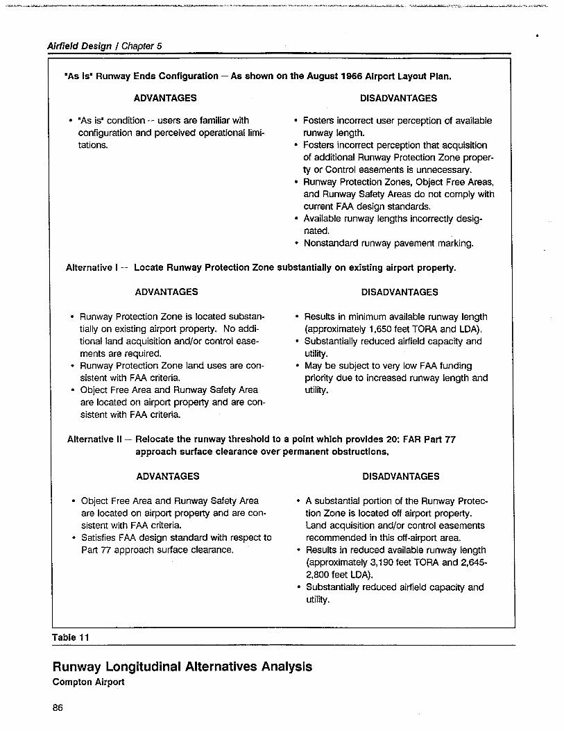
-.~'"~""'"~-'-.'''-.'-'''-''-'''"''''-''''''''''''"''''.-~~=-~--:..;_ _""":~--_.___ _..".'-e~-."-_'::.:,oi-"~":~"'~~-':i~~'~;;,"'";v,;-V~,"';:_.
Airfield Design / Chapter 5.
ADVANTAGES
"As Is" Runway Ends Configuration - As shown on the August 1966 Airport Layout Plan.
· "As is" condition - users are familar withconfiguration and perceived operational limi-tations.
DISADVANTAGES
· Fosters incorrect user perception of availablerunway length.
· Fosters incorrect perception that acquisitionof additional Runway Protection Zone proper-
ty or Control easements is unnecessary.· Runway Protection Zones, Object Free Areas,
and Runway Safety Areas do not comply withcurrent FAA design standards.
· Available runway lengths incorrectly desig-nated.
· Nonstandard runway pavement marking.
Alternative I - Locate Runway Protection Zone substantially on existing airport propert.
ADVANTAGES
· Runway Protection Zone is located substan-tially on existing airport propert. No addi-tionalland acquisition and/or control ease-
ments are required.· Runway Protection Zone land uses are con-
sistent with FAA criteria.· Object Free Area and Runway Safety Area
are located on airport propert and are con-sistent with FAA criteria.
DISADVANTAGES
· Results in minimum available runway length
(approximately 1,650 feet TaRA and LDA).· Substantially reduced airfield capacit and
utilty.· May be subject to very low FAA funding
priority due to increased runway length andutility.
Alternative II - Relocate the runway threshold to a point which provides 20: FAR Part 77approach surface clearance over permanent obstructions.
ADVANTAGES
· Object Free Area and Runway Safety Areaare located on airport propert and are con-sistent with FAA criteria.
· Satisfies FAA design standard with respect toPart 77 approach surface clearance.
DlSADV ANT AGES
· A substantial portion of the Runway Protec-tion Zone is located off airport propert.Land acquisition and/or control easementsrecommended in this off-airport area.
· Results in reduced available runway length
(approximately 3,190 feet TaRA and 2,645-2,800 feet LDA).
· Substantially reduced airfeld capacity andutilty.
Table 11
Runway Longitudinal Alternatives AnalysisCompton Airport
86
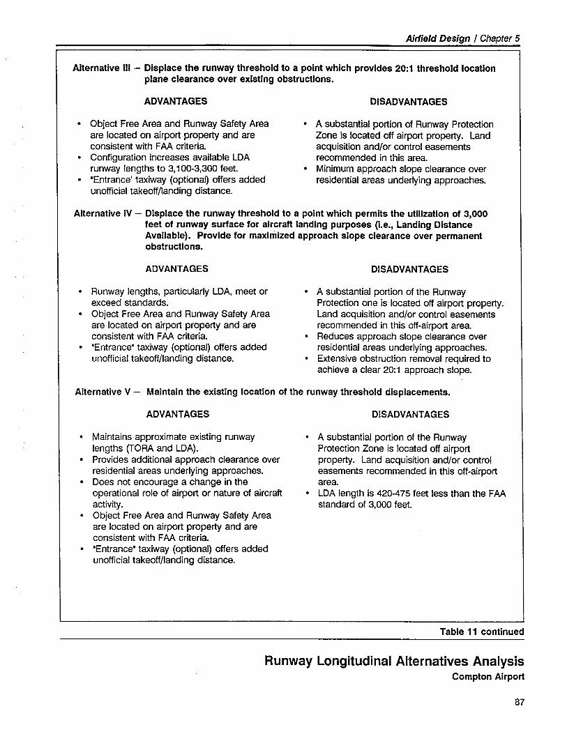
Airfield Design / Chapter 5
Alternative II - Displace the runway threshold to a point which provIdes 20:1 threshold locationplane clearance over exIsting obstructions.
ADVANTAGES
· Object Free Area and Runway Safety Area
are located on airport propert and areconsistent with FAA criteria.
· Configuration increases available LDA
runway lengths to 3,100-3,300 feet.· "Entrance' taxiway (optional) offers added
unoffcial takeoff/landing distance.
DISADVANTAGES
· A substantial portion of Runway ProtectionZone is located off airport propert. Landacquisition and/or control easementsrecommended in this area.
· Minimum approach slope clearance overresidential areas underlying approaches.
Alternative IV - Displace the runway threshold to a point which permits the utilzation of 3,000feet of runway sunace for aircraft landing purposes (i.e., Landing DistanceAvailable). Provide for maximized approach slope clearance over permanentobstructions.
ADVANTAGES
· Runway lengths, particularly LDA, meet orexceed standards.
· Object Free Area and Runway Safety Area
are located on airport propert and areconsistent with FAA criteria.
· "Entrance" taxiway (optional) offers added
unofficial takeoff/landing distance.
DISADVANTAGES
· A substantial portion of the RunwayProtection one is located off airport propert.Land acquisition and/or control easementsrecommended in this off-airport area.
· Reduces approach slope clearance overresidential areas underlying approaches.
· Extensive obstruction removal required to
achieve a clear 20: 1 approach slope.
ADVANTAGES
Alternative V - Maintain the existing location of the runway threshold displacements.
· Maintains approximate existing runway
lengths (TaRA and LDA).· Provides additional approach clearance over
residential areas underlying approaches.· Does not encourage a change in the
operational role of airport or nature of aircraftactivity.
· Object Free Area and Runway Safety Area
are located on airport propert and areconsistent with FAA criteria.
· "Entrance" taxiway (optional) offers added
unofficial takeoff/landing distance.
DISADVANTAGES
· A substantial portion of the RunwayProtection Zone is located off airportpropert. Land acquisition and/or controleasements recommended in this off-airportarea.
· LDA length is 420-475 feet less than the FAAstandard of 3,000 feet.
Table 11 continued
Runway Longitudinal Alternatives AnalysisCompton Airport
87
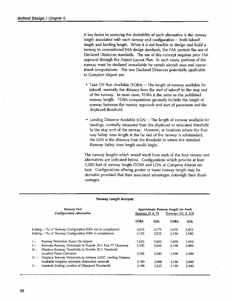
Airfield Design I Chapter 5
A key factor in assessing the desirability of each alternative is the runwaylength associated with each runway end configuration - both takeoff
length and landing length. When it is not feasible to design and build arunway to conventional FAA design standards, the FAA permits the use ofDeclared Distances standards. The use of this concept requires prior FAAapproval through the Airport Layout Plan. In such cases, portions of therunway must be declared unavailable for certin aircraft uses and opera-tional computations. The two Declared Distances potentially applicableto Compton Airport are:
· Take Off Run Available (TaRA) - The length of runway available fortakeoff, normally the distance from the start of takeoff to the stop endof the runway. In most cases, TaRA is the same as the publishedrunway length. TaRA computations generally include the length ofrunway between the runway approach end start of pavement and thedisplaced threshold.
· Landing Distance Available (LDA) - The length of runway available forlandings, normally measured from the displaced or relocated thresholdto the stop end of the runway. However, at locations where the Run-way Safety Area length at the far end of the runway is substandard,the LDA is the distance from the threshold to where the standardRunway Safety Area length would begin.
The runway lengths which would result from each of the four runway endalternatives are indicated below. Configurations which provide at least3,000 feet of runway length (TaRA and LDA) at Compton Airport arebest. Configurations offering greater or lesser runway length may bedesirable provided that their associated advantages outweigh their disad-vantages.
Runway Length Analysis
Runway EndConfiguration Alternative
Approximate Runway Length (in Feet)Runways 7L & 7R Runways 25L & 25R
TORA LOA TORA LOA
Existing - 'As Is' Runway Configuration (OFA not in compliance) 3,670 2,775 3,670 2,810Existing - 'As Is' Runway Configuration (OFA in compliance) 3,190 2,525 3,190 2,580
1- Runway Protection Zones On-Airport 1,650 1,650 1,650 1,65011- Relocate Runway Thresholds to Provide 20:1 Part 77 Clearance 3,190 2,645 3,190 2,880111- Displace Runway Thresholds to Provide 20:1 Threshold
Location Plane Clearance 3,190 2,845 3,190 3,080IV- Displace Runway Thresholds to Achieve 3,000' Landing Distance
Available (requires extens,ive obstruction removal) 3,190 3,000 3,190 3,000v- Maintain Existing Location of Displaced Thresholds 3,190 2,525 3,190 2,580
88
Airfield Design I Chapter 5
In addition to runway length, the following factors require considerationin the selection of the appropriate runway longitudinal design alternative:
· A relocated or displaced threshold cannot be avoided at either end ofthe runways unless the runways are significantly shortened or a sub-stantial number of obstructions are removed or relocated. Neithercourse of action is deemed practicaL.
· The existing "as is" runway end configuration should be modified assoon as practical to provide for appropriately-sized Object Free Areasand Runway Safety Areas. This action will reduce the runways' cur-rent published length of 3,670 feet by approximately 480 feet.
· The parcels located off-airport immediately beyond both ends of therunways are devoted to extensive residential and commercial use.Areas suitable for controlled emergency landings are very limited inthe Airport's approach zones. If feasible, consideration should begiven to preserving available open areas to facilitate aircraft in distressin making emergency landings within approach zones.
Given the design requirements and planning objectives outlined above, itis recommended that Alternative V - Maintain the existing location ofdisplaced thresholds and locate the respective ends of runway pavementto provide for the required Object Free Areas and Runway Safety Areas-be implemented. This alternative runway end design is recommended forthe following reasons:
· The resultant TaRA and LDA lengths exceed and fall only slightlyshort, respectively, of the FAA runway length standard applicable tothis category of airport (i.e., Basic Utility - Stage II).
· The proposed displaced threshold locations permit greater than stan-dard threshold location plane clearance over existing objects andobstructions in the approach zones. This added clearance (27:1 clearapproach slope for Runway 7 system and 38:1 clear approach slopefor Runway 25 system) enhances operational safety and serves tomitigate aircraft noise impacts on residential uses located beneath theapproach surfaces.
· The future runway lengths (TaRA and LDA) are slightly less than theexisting runway lengths, thus serving the same category and type ofaircraft as at present. The future runway configuration will not en-courage a change in the operational role of the Airport or the type ofaircraft using the Airport.
· From an environmental impact perspective, the ultimate runway lengthand threshold locations will be the same as at present. Thus, therunway's impact on adjacent properties will not be significantly
89
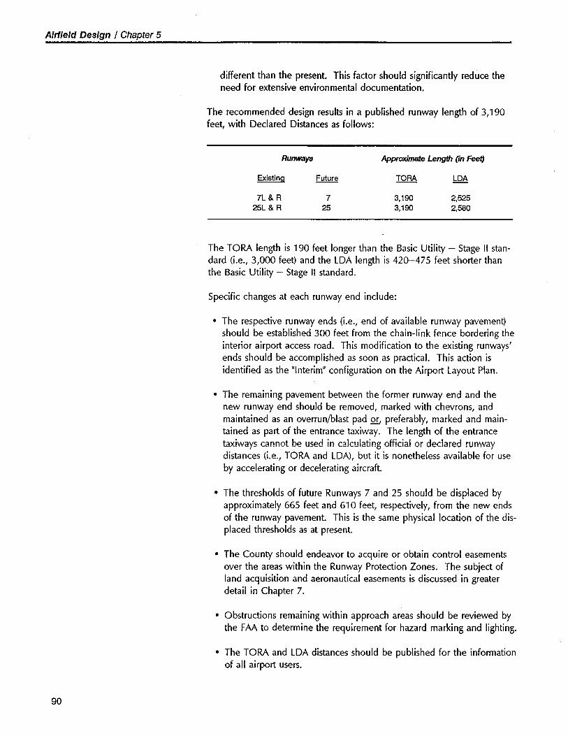
Airfield Design I Chapter 5
different than the present. This factor should significantly reduce theneed for extensive environmental documentation.
The recommended design results in a published runway length of 3,190feet, with Declared Distances as follows:
Runwys Approxmae Leng (in Fet)
Existinq Future TORA LOA
7L & R 7 3,190 2,52525L & R 25 3,190 2,580
The TORA length is 190 feet longer than the Basic Utility - Stage II stan-dard (i.e., 3,000 feet) and the LDA length is 420-475 feet shorter thanthe Basic Utility - Stage II standard.
Specific changes at each runway end include:
· The respective runway ends (i.e., end of available runway pavement)should be established 300 feet from the chain-link fence bordering theinterior airport access road. This modification to the existing runways'ends should be accomplished as soon as practicaL. This action isidentified as the "Interim" configuration on the Airport Layout Plan.
· The remaining pavement between the former runway end and thenew runway end should be removed, marked with chevrons, andmaintained as an overrun/blast pad QL preferably, marked and main-tained as part of the entrance taxiway. The length of the entrancetaiways cannot be used in calculating official or declared runwaydistances (i.e., TORA and LDA), but it is nonetheless available for useby accelerating or decelerating aircraft.
· The thresholds of future Runways 7 and 25 should be displaced byapproximately 665 feet and 610 feet, respectively, from the new endsof the runway pavement. This is the same physical location of the dis-placed thresholds as at present.
· The County should endeavor to acquire or obtain control easementsover the areas within the Runway Protection Zones. The subject ofland acquisition and aeronautical easements is discussed in greaterdetail in Chapter 7.
· Obstructions remaining within approach areas should be reviewed bythe FAA to determine the requirement for hazard marking and lighting.
· The TORA and LDA distances should be published for the informationof all airport users.
90
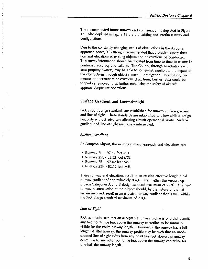
;i.;;. Airfield Design / Chapter 5
:y¡
The recommended future runway end configuration is depicted in Figure13. Also depicted in Figure 13 are the existing and interim runway endconfigurations.
~;Due to the constantly changing status of obstructions in the Airport'sapproach zones, it is strongly recommended that a precise survey (loca-tion and elevation) of existing objects and obstructions be conducted.This survey information should be updated from time to time to ensure itscontinued accuracy and validity. The County, through negotiations witharea propert owners, may be able to somewhat ameliorate the impact ofthe obstructions through object removal or mitigation. In addition, nu-merous nonpermanent obstructions (e.g., trees, bushes, etc.) could betopped or removed, thus further enhancing the safety of aircraftapproach/departure operations.
Surface Gradient and Line-f-Sight
FAA airport design standards are established for runway surface gradientand line-of-sight. These standards are established to allow airfield designflexibility without adversely affecting aircraft operational safety. Surfacegradient and line-of-sight are closely interrelated.
Surface Gradient
At Compton Airport, the existing runway approach end elevations are:
· Runway 7L - 97.57 feet MSL· Runway 25L - 83.52 feet MSL· Runway 7R - 97.02 feet MSL· Runway 25R - 82.52 feet MSL
These runway end elevations result in an existing effective longitudinalrunway gradient of approximately 0.4% - well within the Aircraft Ap-proach Categories A and B design standard maximum of 2.0%. Any newrunway reconstruction at the Airport should, by the nature of the flatterrain involved, result in an effective runway gradient that is well withinthe FAA design standard maximum of 2.0%.
Line-of-Sight
FAA standards state that an acceptable runway profile is one that permitsany two points five feet above the runway centerline to be mutuallyvisible for the entire runway length. However, if the runway has a full-length parallel taxiway, the runway prpfie may be such that an unob-structed line-of-sight exists from any pòint five feet above the runwaycenterline to any other point five feet above the runway centerline forone-half the runway length.
91
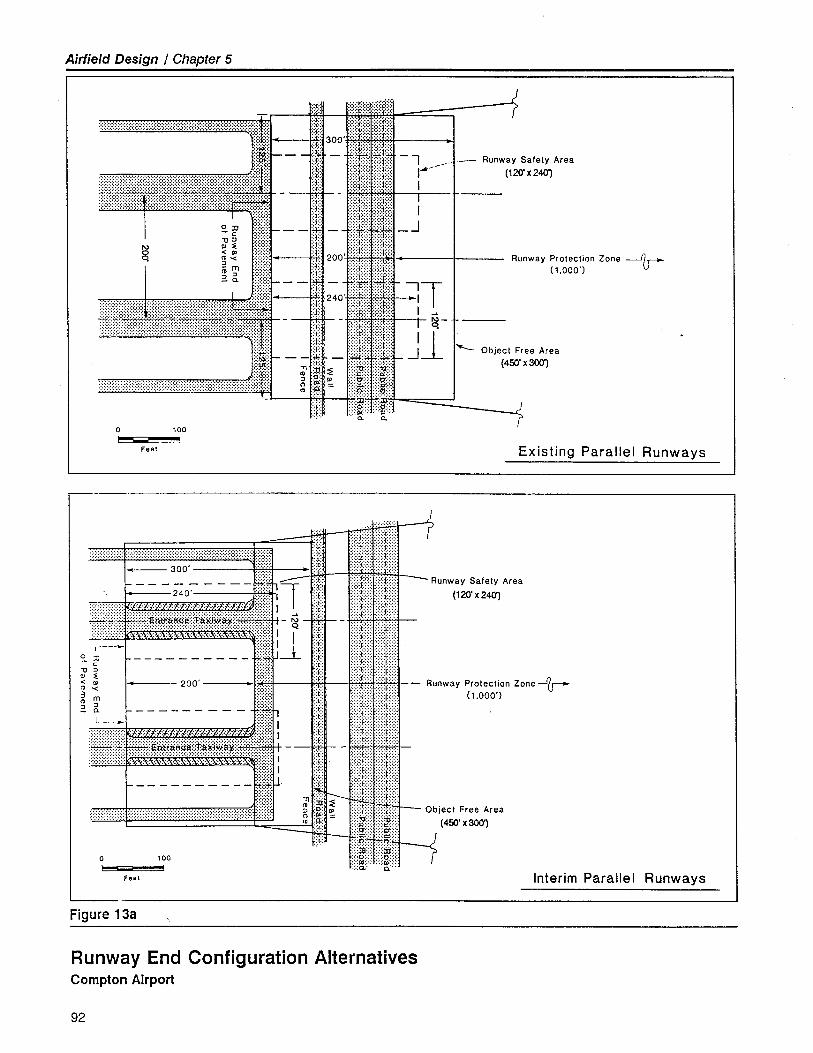
Airfield Design / Chapter 5
::::::~::::: ::::::i:::::.:.:.:c.:.:. ..:.:.i::., ¡"
"'''''';''''''"'''"'''~1- - -~ 3~j¡11_ i---
liir._ - : - !:: :i ::j:: r:tI::t::t i
~~ -- -¿ - :::+rdf-JN -; ~ ::j:: :,:::,::::.:.:.1.:.:.
¡mm¡¡J¡¡i&TimE1n~ - - -I ~: i:m:ü:mff:m:rrr::r:r:tt::::IIfi?i,iJWI_ -_ _in JJ It JJ
',:"::,:,:,:":::":,::,,;,,,:,,,,r:::::/::,:,:,:::::,,::::::::",:::::,::,:::::~,~r:;:ì;: I j: ~ ::.I¡I:I¡ J¡J¡II.'~ ::::::â;;i:J:::::i:: .:.:.'::.,.:.:.:':.:.::~:: :.:.:g,.:." . Ø)
c. c.
.:t:.
o 100~ IFeet
-_._---
::i:~: ::;::t:::; :tI~:~:~
::~:: :~:~:I~:~: ~\/:).:.~:. .:.:.:(.:.:. :::::J:::::;:.'(::.' . j__ 300' ..... ,:::;t:,:, "/):":
- - - ~O- - - - - 4:~~î 'f :::::i¡::::::::':¡:::¡¡
~ ;i:;~ ~!~~~~~~~'1; r 1- - iiiii1ili,~ ~ ' 200 ~ :.:.:~::::.:::::::I:::::::3 m 1: ::::,:"":::'::::':::::~ :; _ - - - - - - - - 1 ::i:: .,:,:,j:::,:,.:::::;t::::::Q. '::r:: :,:,:-1,:,:,: :.:.:.1.:.:.:.I --~ I ::: :,:,:,1::::,:,:,:,:1:,:::
.:....:...::....:..::..:"..:....:....:"...:"....................................................:...:".::.,'.',:.::.,:. I j:, .::::T:,:: ::::::t::::::::i:: ::::::1::::::,:,:,:(':::
#!MMMMW#.WWW::::::::¡:::¡~¡;¡:: i :f - :::::::1:::::: :::A::::::........... ... . r:,:: i ::; ':¡¡::f¡::: ::::t::- - - - - - - - - - - o:::H': J 4. i- ;¡ ::::;::::
: : i il ~ ¡¡¡Iiilii :ii¡i~;:;¡::,.: ::::;; ì:iš
I:J,t:::::::it::,..a a.
........ .......................... ..................
o 1000-Feel
Figure 13a
.Jr
~__ Runway Safely Area
(120' X 2401
Runway Protection Zone --/j
(1.000')
iTi ~
~ Object Free Area
(450' x 301
rExisting Parallel Runways
.. --
- Runway Safety Area
(120' x 240)
Runway Protection Zone-f(1.000')
Object Free Area
(450' x 301Jr
Interim Parallel Runways
Runway End Configuration AlternativesCompton Airport
92
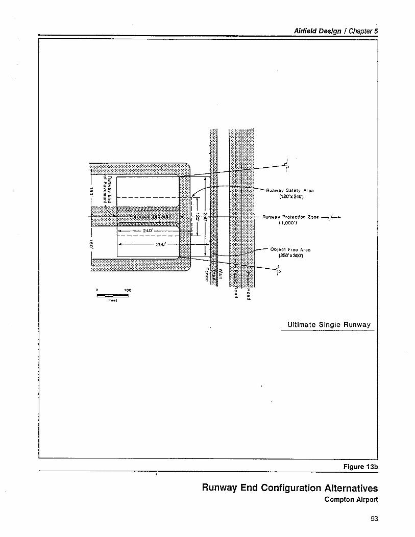
Airfield Design / Chapter 5
~è:::¡:::ttr???:::ttttt::ttttttttIttI:::t¡:~:I ~§ w.....:1:~ ~~m .....)/ 1:"':J 1------ ---- ':*::hT ':f
-.i;i~:~~~:~ir li --------- -_.~. .-..'" 300' tt:~,~ :t~ ".:.:f
i
£II:IIt:??I?I:t:I¡::¡:¡::::::::¡:::::::I::¡:¡~¡~:¡¡:¡:IIIII:J~:l:::
;' ,:ø ~
g :i ~o 100~ IFeet
~r:rJ::t::j::
:1:::j::
.:.:.:\.:.:. :.:.:.~::::::
;::'~;;;': ;""J",:,
:!i;!;!!!¡!i: ":~¡;i.:':~:
:::::t:::IJ¡1"""f;;;;
rtt :I¡ft
::J:::::.::lft: -Runway Safety Area:,:,:j;:;:,: ::::::¡:::::: (120' X 2401
:::::~:::::::::dI::
Runway Protection Zone --IL.
.:::::~:::::: :!:J::I ( 1,000)
::¡¡¡:~iiiii:i:.!¡!!I.'!I' ......r.....¿ø - Obiect Free Area::::X::':' \::(:~: (25' X 301',:,:J,::::"""t,;:;
It.:0 JJo 0'" '"c. c.
Jl
J
P
Ultimate Single Runway
Figure 13b
Runway End Configuration AlternativesCompton Airport
93
Airfield Design / Chapter 5
At Compton Airport, the existing runways' profiles easily meet the FAA'sline-of-sight standard over their entire length. The Runway 7-25 systemline-of-sight is therefore satisfactory. No corrective action is required orappropriate. As noted above, any new runway reconstruction at theAirport should, by the nature of the relatively level terrain involved, resultin an acceptable line-of-sight along the entire length of the runway.
RUNWAY LATERAL REQUIREMENTS
Table 9 identifies the standards for distances to facilities, objects, andstructures located laterally from the runway. In a number of importntrespects, the existing airfield configuration does not comply with currentFAA lateral standards. Noncompliance items include: Object Free Area,Runway Safety Area, runway to taxiway centerline separation, BuildingRestriction Line, Aircraft Hold Line, Aircraft Parking Limit, and Part 77transitional surfaces.
Runway Width
Compton Airport's existing runway width is 60 feet. The FAA designstandard for an airport such as Compton - Airport Reference Code B-1
(Small AirplanesNisual) - recommends a width of 60 feet. Due to theabsence of any significant runway crosswind component or other opera-tional requirement, the 60-foot width is judged to be satisfactory for bothpresent and future use.
Object Free Areas and Runway Safety Areas
As noted in the discussion of runway longitudinal requirements, none ofthe Airport's existing Object Free Areas and Runway Safety Areas meetscurrent FAA standards. The width standards for an Object Free Area and
Runway Safety Area appropriate to Compton Airport are 250 feet and120 feet, respectively. The existing and ultimate runway configurations asdepicted in the Airport Layout Plan provide for adequately-sized ObjectFree Areas and Runway Safety Areas.
Runway-to- Taxiway Separation
At Compton Airport, the appropriate FAA standard separation distancebetween the runway centerline and parallel taxiway centerline is 150 feet.This dimension is considerably greater than the Airport's existing 1 pS-footrunway/taxiway separation distance. It is recommended that the stàndard150-foot distance be implemented IÂhen the runway/taxiway system isreconstructed.
94
Airfield Design / Chapter 5
Building Restriction Line
The new FAA design guidelines recommend that the Building RestrictionLine (BRL) encompass the Runway Protection Zonesi areas required forairport traffic control tower clear line-of-sighti and all airport areas withless than 35-foot clearance under the FAR Part 77 surfaces. This is anFAA design recommendation, not a strict standard. As applied to Comp-ton Airporti the most restrictive aspect of this recommendation is that theBRL encompass all airport areas with less than 35-foot clearance underthe FAR Part 77 surfaces. The resultant BRL would be located approxi-mately 370 feet from the runway centerline, thereby encompassing virtu-ally all of the existing airport structures along the runways' north andsouth sides and substantially eliminating a major portion of the Airport'sfacility development area. A 370-foot BRL on the Airport's north sidewould also encompass a significant portion of the off-airport residenceslocated along the south side of 156th Street.
In light of the type of aircraft using the Airport (Le., small general aviationaircraft operating in predominantly visual conditions), it is not unreason-able to allow aviation-related structures to be developed as close to therunway as permitted by FAR Part 77 transitional surfaces criteria. On thisbasis, a 15-foot-high hangar structure could be located as close as 230feet from the runway centerline and a 20-foot-high structure could belocated as close as 265 feet from the runway centerline. Furthermore,hangars and other structures could be developed that penetrate the run-way's Part 77 transitional surfaces. Such penetrations, while not desir-able, may be necessary to accommodate hangar demand. This is particu-larly applicable with respect to hangars located along the Airport's northperimeter walL. The FAA's review and approval of any such penetrationswould be required prior to construction.
The existing close-in hangars paralleling the north and south sides ofRunways 7L-25R/7R-25L do not comply with these FAR Part 77 stand-ards. As part of the FAA's approval of the Airport Layout Plan, a formal
FAA airspace review of these penetrations will be required to accuratelyassess the airspace impact of the penetrations and determine correspond-ing hazard mitigation requirements.
Aircraft Hold Line
In accordance with FAA design standards appropriate to Compton Airport,no fixed or movôble object should be situated closer than 125 feet fromthe runway centerline. Therefore, the appropriate runway/taxiway hold
line location is 125 feet from the runway centerline. This hold lineshould be clearly marked at all runway/taxiway intersections.
95
Airfield Design I Chapter 5
A taxiway is a defined path es-
tablished for the taxiing of air-craft from one part of an airportto another. A taxi/ane is thatportion of the aircraft parking
area used for access between
taxiways and aircraft parkingpositions. Taxiways and taxi-lanes serving the internal build-ing area are discussed in Chap-ter 6 - Building Area Develop-
ment.
96
TAXIWAY REQUIREMENTS
Parallel Taxiways
The proper design of the future north and south side parallel taxiways is akey factor in the efficient development and utilization of the Airport. Dueto the limited airport land area available for development, the paralleltaxiway system significantly influences the Airport's overall design andoperation.
Previous sections of this chapter established 150 feet as the desired sepa-ration distance between the runway centerline and parallel taxiway cen-terline. As noted, this dimension is 45 feet greater than the existingseparation dimension of 105 feet.
The existing parallel taxiways are approximately 20-feet wide, with 35-feet of separation between the taxiway centerline and the Aircraft ParkingLimit. The Airplane Design Group I standard taxiway width is 25 feet,with a taxiway centerline to Aircraft Parking Limit separation of 45 feet.Due to airfield congestion and the proximity of aeronautical supportareas, it is recommended that 35 feet be established as the taxiway widthfor both future parallel taxiways at Compton Airport. Further, it is recom-mended that the future Aircraft Parking Limit be established 45 feet fromthe north side parallel taxiway centerline and 65 feet from the south sideparallel taxiway centerline. This additional clearance on the south sidepermits added flexibility and safety in the operation and maneuvering ofaircraft and vehicles on the ground, particularly in the vicinity of the busyterminal and fixed base operations areas.
The parallel taxiways should extend the full length of the runway pave-ment, including access to the entrance taxiway at each runway end. Aholding bay/run up pad - large enough to accommodate two or three
small airplanes - should be provided near the end of each parallel taxi-way. Consideration should be given in siting these holding bays to theeffects of prop washf¡et exhaust on persons, aircraft, and facilities locatednear the runup areas. In addition, off-airport trees located in the vicinityof the runways' approach ends, particularly Runways 25L and 25R,should be topped or removed. These trees substantially interfere with theability of pilots awaiting departure to see arriving aircraft on shortlowfinal approach.
Exit Taxiways
Three mid-field exit taxiways currently serve each runway. The generallocations of these mid-field exit taiways appear adequate for the types ofaircraft currently using the facility. The precise location of each exit
~iAirfield Design / Chapter 5
:1
,J'1
- taiway may be slightly adjusted in the future as necessary to align themwith runway thresholds and principal building area taxilanes and to en-hance runway capacity.
In response to user input, the width of the three mid-field exit taiwayshas been established at 50 feet, with relatively generous fillets. Thisgreater-than-standard width will permit increased user safety during high
wind conditions and wil somewhat enhance runway capacity by expedit-ing the clearing of aircraft from the runway.
As part of this analysis, the possible use of high-speed exit taxiways wasexplored. While such taxiways have the potential to slightly decreaserunway clearing times and marginally increase capacity, there is insuffi-cient area available between the runway and parallel taxiway to properly"configure a high-speed exit taxiway. Therefore, all exit taxiways at Comp-ton Airport are of the standard 900 configuration.
For the longer term, however, the airfield design may provide sufficientflexibility to permit the implementation of a "drift-off' taxiway system. A"drift-off' taxiway permits landing airplanes to exit the runway in an expe-ditious manner at virtually any point along the full length of the runway.Such a taxiway system could prove desirable if future operational demandrequires increased runway capacity. Utilizing a "drift-off' taxiway systemto expedite runway clearing has the potential to increase runway capacityand utility. The future implementation and use of the "drift-off' taxiwaysystem should be carefully coordinated with FAA and airport traffic con-trol tower representatives. It is suggested that no airport developmentaction be taken that would physically preclude the futurE! implementationof the "drift-off' taxiway concept at Compton Airport.
Entrance Taxiways
As an operational enhancement, it is suggested that entrance taxiways beestablished at each runway end. While such entrance taiways are notrecognized by the FAA as contributing to runway length calculations (i.e.,TORA and LDA), the added length they provide does contribute to en-hanced levels of aircraft operational safety and efficiency. In addition,the entrance taxiway pavement effectively controls surface erosion, acts asan overrun/blast pad, and permits an alternate means of accessing eachrunway end.
97
Airfield Design / Chapter 5
OTHER AIRFIELD DESIGN ELEMENTS
Pavement Strength
As noted earlier, the present and future operational role of ComptonAirport is to serve general aviation aircraft having maximum certificatedweights of 12,500 pounds or less. Therefore, it is recommended that allprimary airfield operating surfaces (e.g., runways, taxiways, aprons, andramps) be designed and constructed to accommodate an aircraft wheel-loading of 12,500 pounds for single-wheel configuration landing gear.
As is typica.l at general aviation airport such as Compton, large, heavyrefueler trucks may exceed this wheel-loading limit. Therefore, prior tooperating refueler trucks on airfield surfaces, it is suggested that a deter-mination be maòe as to the suitabiiity of such operations and their impacton airfield pavement surfaces.
Marking
Runways
The existing runway marking scheme consists of a centerline, edge stripes,runway designation numbers, and displaced threshold markings at bothrunway ends. Such markings are characterized as "Basic" by the FAA.These markings are consistent with the visual nature of the Airport'soperations. The markings are in good condition. Adjustments to thismarking scheme to reflect proposed airfield changes (i.e., non precisioninstrument approach, displaced thresholds, entrance taxiways, lead-instriping, etc.) are indicated on the Airport Layout Plan.
Taxiways
The parallel taxiways and exit taxiways are currently marked by centerlinestripes, building area side lead-in stripes, and, in some locations, runwayhold lines. Due to the configuration of the parallel taxiway, the holdlines at the existing runway ends are marked at a position approximately100 feet laterally from the runway centerline. Current FAA design stan-dards specify a minimum distance of 125 feet for runways serving aircraftin Aircraft Approach Categories A and B. Currently, there are no holdline markings on the mid-field runway exit taxiways.
Appropriate hold line markings should be located at all runway/taxiwaycrossings. In some locations, the use of taxiway edge striping is recom-mended to better differentiate the taxiway from similar-appearing contigu-ous surfaces.
98
Airfield Design I Chapter 5
Other
The notation "COMPTON-EL.97'" appears in large block letters on thepavement near the Airport's segmented circle. While such marking maybe desirable from a user perspective, it is not required by the FAA andmay be confusing to transient aircraft operators, particularly when taiingat night on the north side parallel taxiway.
Lighting
The existing runway lights on Runway 7R-25L are of medium-intensityand are well used but in operable condition. Nonetheless, it is recom-mended that these lights be replaced by a new Medium-Intensity RunwayLighting system serving Runway 7L-25R when Runway 7L-25R is recon-structed. An automated runway light activation system (photocell/timer)and/or pilot-activated system are recommended as energy-saving mea-sures.
To aid in the nighttime movement of aircraft on the taxiways, a partialtaxiway lighting system is desirable. Taxiway edge lights are desirable forall entrance and exit taxiways and along the runway-side edge of theparallel taxiways. To supplement these lights, taxiway centerline reflec-tors and/or edge reflectors are desirable.
Approach and Landing Aids
Instrument Approach Capabilty
Compton Airport is not presently served by an instrument approach. TheAirport is considered a "visual" facility and all arrival operations must beconducted in accordance with Visual Flight Rules and procedures. Air-craft may depart the Airport in accordance with either Visual or Instru-ment Flight Rules and procedures, as appropriate. Aircraft departing theAirport under instrument conditions are handled by Los Angeles Depar-ture Control.
Compton Airport, however, is equipped with a low-frequency, nondirec-tional radio beacon (COMPTON NDB - 378 kHz). This beacon is forVFR-use-only and is considered to be of significant value to pilots inlocating the Airport at night and under conditions of restricted visibility.The beacon's transmitting antenna wire is presently suspended betweenthe north ends of T-Hangar Buildings F and G. It is recommended thatthis older-style antenna wire be upgraded and the antenna relocated sothat it does not potentially interfere with operating aircraft.
Over the years, users of Compton Airport have suggested that some formof instrument approach capability be established at the Airport. Such
99
Airfield Design I Chapter 5
capability would permit authorized users to approach the Airport in lessthan visual meteorological conditions. In addition, such instrument ap-proach capability would facilitate the safe and efficient arrival of autho-rized users in marginal visual meteorological conditions.
Considering the operational role of the Airport, its physical layout, and itslocation within the Los Angeles airspace complex, it is likely that anyinstrument approach procedure established at Compton Airport would beof the "non precision" type. Examples of nonprecision instrumentapproaches include: NDB, VOR, LaC, LOA, SOF, and LORAN-C. Asnoted previously, the Airport's configuration and the presence of obstruc-tions to air navigation may preclude the attinment of "straight-in" instru-ment approach minimums. However, the Airport may still qualify for anon precision instrument approach which terminates in a visual or circlingmaneuver to a landing.
Since an operational low-frequency nondirectional beacon (COMPTONNDB) is already located on the Airport, it is suggested that this VFR-use-only beacon be upgraded and established as the FAA-authorized non pre-cision instrument approach serving Compton Airport. Formal FAA reviewand analysis will be required to determine the exact procedure and mini-mums associated with such an approach.
Many aircraft operators view the NDB approach procedure as the mostbasic and least desirable form of instrument approach. The NDB's mainadvantage is its low cost of installation and operation. As an alternativeto the NDB approach procedure, one or more of the other non precisioninstrument approach procedures could be established at Compton Air-port. Of particular interest in this regard is the newly-emerging instru-ment approach capability based on LORAN-C navigational equipment.
As far as is practical, the airfield configuration and facilities identified inthe Master Plan have been designed in accordance with the FAA stan-
dards and specifications for a "visual" category airport capable of accom-modating a "circle-to-Iand" non precision instrument approach.
Airport Rotating Beacon
The Airport's rotating beacon is mounted on a dedicated pole in thesoutheast corner of the Airport. Its location and function appear satisfac-tory for both the present and future.
100
Airfield Design I Chapter 5
Visual Glide Slope Indicator(VGSI) is the generic term for thegroup of airport visual landingaids which includes Visual Ap-proach Slope Indicators (VAS i) ,
Precision Approach Path Indica-tors (PAPI), and Pulsed LightApproach Slope Indicators(PLASI). When FAA fundingpays for this equipment, which-ever type receives the lowest bid
price wil be installed, unless theairport owner wishes to pay thedifference for a more expensiveunit.
Visual Glide Slope Indicators
A two-box Visual Approach Slope Indicator (VASI) is sighted at the ap-proach end of Runways 25L and 25R. To significantly enhance opera-tional safety and assist in the reduction of noise impacting propertiesunderlying the runway approaches. the installation of an additional VGSIat the approach end of Runway 7 (future) is highly recommended. Tofurther enhance operational safety by providing an added margin of clear-ance over existing obstacles in the runway approaches and to reducenoise impacts, it is recommended that consideration be given to establish-ing the VGSl's visual glide path at a higher-than-normal angle (e.g., up to3.9 degrees), as opposed to the standard 3.0-degree glide path.
Runway End Identifier Lights
Although not required to augment an instrument approach procedure,Runway End Identifier Lights (RElls) are presently installed on ComptonAirport's Runway 25L. For the future, it is recommended that both endsof the primary runway (i.e., Runway 7-25) be equipped with REIL's.RElls at both runway ends will significantly aid pilots in locating therunway ends, particularly at night and under the conditions of restrictedvisibility that are characteristic of the Airport's urban environs. RE1L's willalso assist pilots in quickly locating the Airport within the heavily-traf-ficked central Los Angeles airport complex. Because of the nearby pres-ence of residences and businesses, a special study is suggested to deter-mine appropriate ways of mitigating REIL flash annoyance that couldpotentially impact off-airport land uses.
Segmented Circle and Wind Cone
FAA airport design standards suggest that the Airport be equipped with asegmented circle and wind cone. A wind tee is not required by the FAA.A segmented circle with appropriate traffc pattern indicator markings,wind tee, and wind cone is presently located in an open area on theAirport's northern side. These facilities are lighted and in good condition.
The ultimate location of the segmented circle and wind cone is significantin that its placement will impact the efficient development and use of thealready constrained apron area. The segmented cirde and wind coneshould be located in a readily visible area that is subject to typical winds.The segmented circle and wind cone should not interfere (physically orvisually) with aircraft operating on the parallel taiway. The only viableultimate location for the segmented circle and wind cone is in the vicinityof the former airport traffic control tower site. While not an optimumlocation from a wind exposure perspective, this location minimizes thecircle's impact on the use of the north side parallel taxiway. Supplemen-tal wind indicators, as noted below, can provide pilots with additionalwind information near the runway touchdown zones.
101
Airfield Design I Chapter 5
Supplemental Wind Indicators
The Airport is not presently equipped with supplemental wind indicators.It is recommended that supplemental wind indicators (e.g., lighted windcones) be installed near the touchdown zone of each runway end. Sug-gested locations are indicated on the Airport Layout Plan.
Radio Communications
The Airport does not presently make use of the UNICOM radio commu-nication system for ground-to-air advisories. Aircraft operating in theCompton Airport traffic pattern utilize the Common Traffic Advisory Fre-quency of 122.9 (MUL TICOM) to advise each other as to their respectivelocations and intentions. As the Airport increases in activity and complex-ity, it is suggested that this informal MUL T\COM traffic advisory system besupplanted by ground-based UNICOM advisory service and/or an airporttraffic control tower.
Automated Weather Observing System
Official weather observations are not currently taken at Compton Airport.Neither the airport staff nor fixed base operations personnel are presentlycertified or equipped to provide such observations. Pilots desiring anofficial weather observation for the Compton Airport area must lIse theobservations taken at nearby Long Beach, Torrance Municipal, or Haw-thorne Municipal airport.
To provide Compton Airport users with more complete and accurate localweather information, the County has budgeted funds to equip the Airportwith an Automated Weather Observing System (AWOS). The proposedAWOS installation at Compton Airport will permit real-time disseminationfor weather observations to both airport users and interested parties (e.g.,local community, news media, National Weather Service, Civil Oefense,etc.). The AWOS system consists of various environmental sensors (ane-mometer, barometer, temperature/dew point indicator, cloud height,surface visibility, etc.), a data processor, a voice synthesizer, and a radiotransmitter. A 20-30 second weather information message is transmittedcontinuously on an assigned aeronautical radio frequency. Typically,AWOS data can also be accessed by telephone.
As part of the Master Plan, an analysis of potential sites for the location ofthe AWOS sensing equipment was conducted. This analysis indicatedthat there is no readily developable site, either on- or off-airport, thatfully complies with the AWOS siting criteria identified in FAA Order6560.20. Accordingly, a special study.will be required to site the AWOSequipment at Compton Airport. The established siting criteria wil haveto be adjusted to permit the siting of the AWOS in a less than optimumlocation. AWOS sites to be considered should include:
102
Airfield Design I Chapter 5
· The former airport traffic control tower site on the Airport's north side.
· On top of a suitable structure (e.g., FBO hangar, terminal building,etc.).
It should be noted that tne siting of the AWOS may result in the loss ofnumerous, already-limited aircraft parking positions, or otherwise furtherconstrain airport development.
Runway Reconstruction
To accomplish all of the runway and taxiway improvements noted above,it will be necessary to close Runway 7L-25R for certin periods of time.Through coordinated construction engineering and scheduling, it is possi-ble to keep the Airport fully operational and available to both fixed-wingand rotary-wing aircraft during the 4-6 week runway reconstruction peri-od. Such coordination should be accomplished as an integral element ofthe runway reconstruction engineering design process.
103

104
~ ----
. Building AreaDevelopment
6
Building Area Development
OVERVIEW
The building area of an airport encompasses all of the airport propertnot devoted to runways, major taxiways, required airspace and surfaceprotection areas, and other airfield-related functions. Facilities and servic-es typically found in a public-use general aviation airport building areainclude:
- Based aircraft tiedown and hangar space
- Transient aircraft parking - fixed-wing and helicopter- Terminal area facilities - airport administration/operations offices,
pilot briefing/flight planning area, passenger waiting area, restrooms, public telephone, etc.
- Fuel storage and dispensing equipment - fuel island and/or refuel-er trucks
- Fixed base operations facilities - multi-service and specialized- Access roads and vehicle parking
- Security/perimeter fencing and access gates, lighting, and signing
Also common, particularly at busy general aviation airport, are:
- Airport traffic control tower
- Airfield maintenance facility- Aircraft washing area
- Owner-performed aircraft maintenance enclosure- Public airport viewing area
- Aviation support facilities such as commercial/industrial buildings,coffee shop/restaurant, etc.
This chapter examines the various factors and considerations that affectthe siting and development of future building area facilities at ComptonAirport and alternative ways of accommodating projected demand. Thechapter concludes with a staging plan for development of the recom-mended building area improvements.
105
Building Area Development I Chapter 6
DESIGN FACTORS
Many design factors influence the planning and subsequent developmentof an airport's building area. Figure 14 graphically summarizes the keyissues and opportunities associated with the design and development ofthe Compton Airport building area. For discussion purposes, these designfactors can be grouped into the following five categories:
- Compliance with FAA Airport Design Standards
- Maximized Development and Use of the Airport's Available Build-ing Area
- Accommodation of Increased Helicopter Activity- Enhancement of Airport Safety and Security- Development Staging
A summary discussion of each of these five factor categories follows.
Compliance with FAA Airport Design Standards
Structures, fixed objects, and aircraft parking areas must be located certinminimum distances from runways and taxiways. These distances arespecified by FAA airport design standards. As noted in Chapter 5-AirfeldDesign, the appropriate present and future design category for ComptonAirport is Airport Reference Code B-1 (Small AirplanesNisual). According-ly, the following FAA design criteria are recommended for future applica-tion at Compton Airport:
· Runway centerline to parallel taxiway centerline separation of 150feet.
· Runway centerline to aircraft Hold Line dimension of 125 feet. Thisdimension influences the placement of aircraft holding bays/runuppads.
· North side parallel taxiway centerline to Aircraft Parking Limit (APUseparation of 45 feet.
· South side parallel taxiway centerline to Aircraft Parking Limit (APUseparation of 65 feet.
Maximized Development and Use of the Airport's AvailableBuilding Area
As noted in the previous chapter, acquisition of additional land area topermit expansion of the Airport does not appear to be economicallyfeasible during the 20-year planning period. Therefore, the development
106
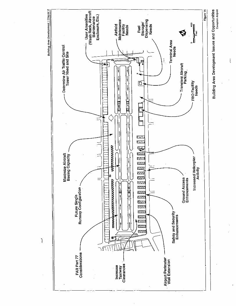
FA
R P
art 7
7C
onsi
dera
tions
Incr
ease
Tax
iway
Cle
aran
ces
, Air
port
Per
imet
erW
all E
xten
sion
."...
;~
Bui
ldin
g A
rea
Dev
e/op
men
l I C
hapt
er 6
Max
imiz
e A
ircr
aft
Basing Capacity
Det
erm
ine
Air
Tra
ffc
Con
trol
,T
ower
Nee
d an
d Si
te
Use
r A
men
ites
(Was
\1 R
ack,
Air
craf
tM
aint
enan
ceE
nclo
sure
, Etc
.)
Ain
ield
Mai
nten
ance
Faci
ltyN
eeds
Fuel
Stor
age/
Dis
pens
ing
Nee
ds
4Jo 400
i- 'i
Feel
Figure 14
Fut
ure
Sin
gle
Run
way
Con
figu
ratio
n
Saf
ety
and
Sec
urity
Enh
ance
men
ts
Ter
min
al A
rea
Nee
ds
Gro
und
Acc
ess
Enh
ance
men
tsT
rans
ient
AIr
craf
tParking _
FBO
Fac
ilty
Nee
dsIncreased Helicopter
Act
ivity
Bui
ldin
g A
rea
Dev
elop
men
t Iss
ues
and
Opp
ortu
nitie
sC
ompt
on A
irpor
t
Building Area Development I Chapter 6
and use of the Airport's available building area must be maximized if theAirport is to accommodate its forecast demand. In addition, Airportactivity forecasts indicate that during the mid-point of the 20-year plan-ning period, aircraft basing demand requirements will necessitate theconversion of the airfield from a parallel runway configuration to a singlerunway configuration. Any development and use of the building areamust be accomplished in a manner that is consistent with both the pres-ent and future airfield configurations.
Accommodation of Increased Helicopter Activity
A relative!y recent and growing element of the Airport's aeronauticalactivity is the increased use of helicopters by Airport-based municipalservices agencies. At present, the City of Compton Police Oepartmentbases three helicopters at Compton Airport. It is anticipated that otherarea municipal agencies will choose to base their helicopters at the Air-port. This increased helicopter activity and associated facility require-ments must be provided for in the building area plan. In addition, theaerial interaction of fixed-wing aircraft and helicopters in the Airporttraffic pattern and on the ground must be carefully considered in thelayout of the Airport's airfield and building area.
Enhancement of Airport Safety and Security
Of primary importance to any airport's development and use is the needto enhance operational safety and security. High levels of safety andsecurity benefit both the users of the airport as well as the citizens livingin the vicinity of the airport. At Compton Airport, the somewhat con-strained land area available for airfield and facility development requiresthat considerable attention be given to ensuring the continued safety andsecurity of Airport operations. With regard to airfield safety, adequateObject Free Areas, Runway Safety Areas, and runway setbacks must beprovided. Suitable perimeter fencing/walls, controlled access gates, andarea lighting will be necessary to provide for adequate levels of usersecurity. All of these actions must be accomplished in a manner whichprovides for maximum development and utilization of the Airport.
Development Staging
Another important factor in the preparation of a building area plan is thetiming of future development. The objective is to have a plan that isflexible enough to adapt to changes in type and pace of facility demands,is cost effective, and also makes sense at each stage of development.Sometimes, the best location for facilities needed in the short term mayconflict with the optimum long-range plan. Additionally, a staging planthat requires removal of old facilities or construction of new ones before
107
/Building Area Development/ Chapter 6
they are clearly necessary can be costly. At Compton Airport, the mostsignificant factor in the staging of building area development will be thefuture conversion of the airfield from the present parallel runway configu-ration to a single runway configuration. All facilities and improvements inthe building area must be compatible with both the present and futureairfield configurations.
FACILITY REQUIREMENTS - SOUTH SIDE BUILDINGAREA
The southern half of Compton Airport has historically served as the focusfor public and commercially-oriented building area development. Thisdevelopment includes terminal facilities, airport administrative/operationaloffices, airfield maintenance facilities, aircraft fueling facilities, fixed baseoperations hangars, and public auto parking. It is anticipated that thisarea emphasis will continue throughout the 20-year planning period.
Terminal Area
The master plan analysis indicates that the southeast section of the Airportis the optimum location for continued development of the public terminalarea and related facilities and services. The factors considered in theselection of this location include:
· Terminal area is readily visible to general public and airport users.
· Terminal area is located adjacent to primary area access roads (e.g.,adjacent to Alondra Boulevard). This location permits easy groundaccess.
· Terminal area is located adjacent to runway/taxiway system (i.e., adja-cent to south parallel taxiway). This location permits easy aircraftaccess.
· There is a substantial existing commitment to terminal development inthat area.
· Clear developable space is available for expansion.
· Terminal area is adjacent to fixed base operations area.
· Utilities are readily available.
· Terminal area is remote from incompatible off-airport uses such assingle-family residences.
108
Building Area Development I Chapter 6
· Other sections of the Airport are either heavily committed to otheruses (e.g., permanent T-hangar structures along the Airport's southwestsid~), or do not lend themselves to terminal development and use(e.g., poor vehicular access to north side building area).
In mid-1991, the County constructed a 2,880 square foot modular termi-nal building on the site identified in the Airport Layout Plan (seè Chapter2-Figure 1). This new building provides space for the following functions:
- Airport-user lounge, lobby, and deck
- Coffee shop/kitchen/office/storage
- Airport administrative offices (3
- Public rest rooms and telephones
- Public airport viewing area
The terminal building floor plan is depicted in Figure 15. The modularbuilding has been designed to permit phased expansion as may be re-quired by future demand. It is anticipated that the new structure, aspresently configured, will be adequate for the initial half of the 20-yearplanning period. Sufficient space should be provided in the terminal areafor a 50% expansion of the terminal building in the latter part of theplanning period.
Aircraft Fueling Facilities
An important consideration in the design and use of the new terminalarea is the appropriate location and type of aircraft fueling facilities. Asindicated in Chapter 4-Airport Activity and Capacity Analysis, the large
majority of aircraft operations at the Airport will be generated by single-engine and light twin-engine piston-powered general aviation aircraft.Turbine-powered aircraft will comprise only a small portion of the Air-port's overall activity.
Accordingly, it is recommended that the Airport's aircraft fueling facilitiesbe initially oriented to servicing piston-powered aircraft with at least twogrades of aviation gasoline. Ideally, these two grades of aviation gasolinewould be 80 octane and 100 octane. As an alternative, the Airport couldoffer 100LL octane aviation gasoline and a suitable grade of automotivefuel (i.e., MOGAS). Low octane gasolines (e.g., 80-octane AVGAS andMOGAS) should prove very attractive to the users of the Airport operatingolder recreational and enthusiast types of aircraft. It is recommended thata survey of Airport users be conducted to determine the demand for lowoctane gasoline.
Also worthy of consideration is the potential for the Airport to store anddispense let-A fuel to the City of Compton Police Department's (CPO)turbine-powered helicopters based on the Airport. To provide this capa-bility, a third storage tank or dedicated refueling truck would be requiredfor the let-A fueL. The let-A fuel would be most efficiently dispensed to
109
Building Area Development I Chapter 6
the CPD helicopter and the occasional civilian or military turbine-pow-ered aircraft through the use of refueler trucks. A third product tankcould be located with the Airport's aviation gasoline tanks or it could belocated in a separate area closer to CPD's helicopter operations. Typical-ly, a single-location fueling facility is less costly to. develop and operatethan a multiple-location fueling facility.
A variety of alternative locations for the Airport's aircraft fueling facilitieswere considered. Ideally, the fueling facilities should be located in anarea readily accessible by taxiing aircraft and bulk fuel delivery trucks. Inaddition, the facilities should be located in the vicinity of the terminalbuilding/airport administrative offices to permit effective cross-utilizationof airport operational personnel and to enhance the safety and security offueling operations. The existing location of the fueling facilities (under-ground storage tanks and fuel dispensing island) adequately satisfies thesesiting objectives. An alternative site, to the west side of the new terminalbuilding, is also suitable and has the advantage of being somewhat closerto the fixed base operations area. In addition, the west side site wouldpermit the continued operation of the existing fueling facilities whilereplacement facilities were being constructed. The west side site has theprimary disadvantage that it would require the relocation of an estimated20 aircraft parking positions from the west to east side of the terminalbuilding. These parking positions would then be located a considerabledistance (approximately 800 feet) from the fixed base operations area.
For the purposes of this master plan, the Airport's future aircraft fuelingfacilities are depicted as remaining essentially where they are presentlylocated. The future fuel island has been relocated slightly to the north(approximately 50 feet) to permit more efficient utilization of the availableapron area. In keeping with the County's established operational format,
a "fuei island" configuration is depicted. The fuel island configurationoffers the added benefit that 24-hour access, credit card-activated, self-fueling capability can be made available if so desired by the airport oper-ator. The fuel island, with associated fuel dispensing equipment andunderground storage tanks, should be located as shown on the AirportLayout Plan in the immediate vicinity of the terminal building/airportadministrative offices and transient aircraft parking area. If justified bydemand, refueler trucks could be utilized to supplement the fuel islandfacilities.
Airfield Maintenance Facility
A dedicated facility is required to accommodate airfield maintenanceservices and equipment storage. The site should be well-located withrespect to both airfield and roadway access. In addition, the County hasexpressed a preference for an airfield maintenance facility that is locatedin the vicinity of the terminal building and/or aircraft fueling facility. Thiscollocation would permit the cross-utilization of County airport operationsand maintenance personnel, as well as offering some security benefits.
110
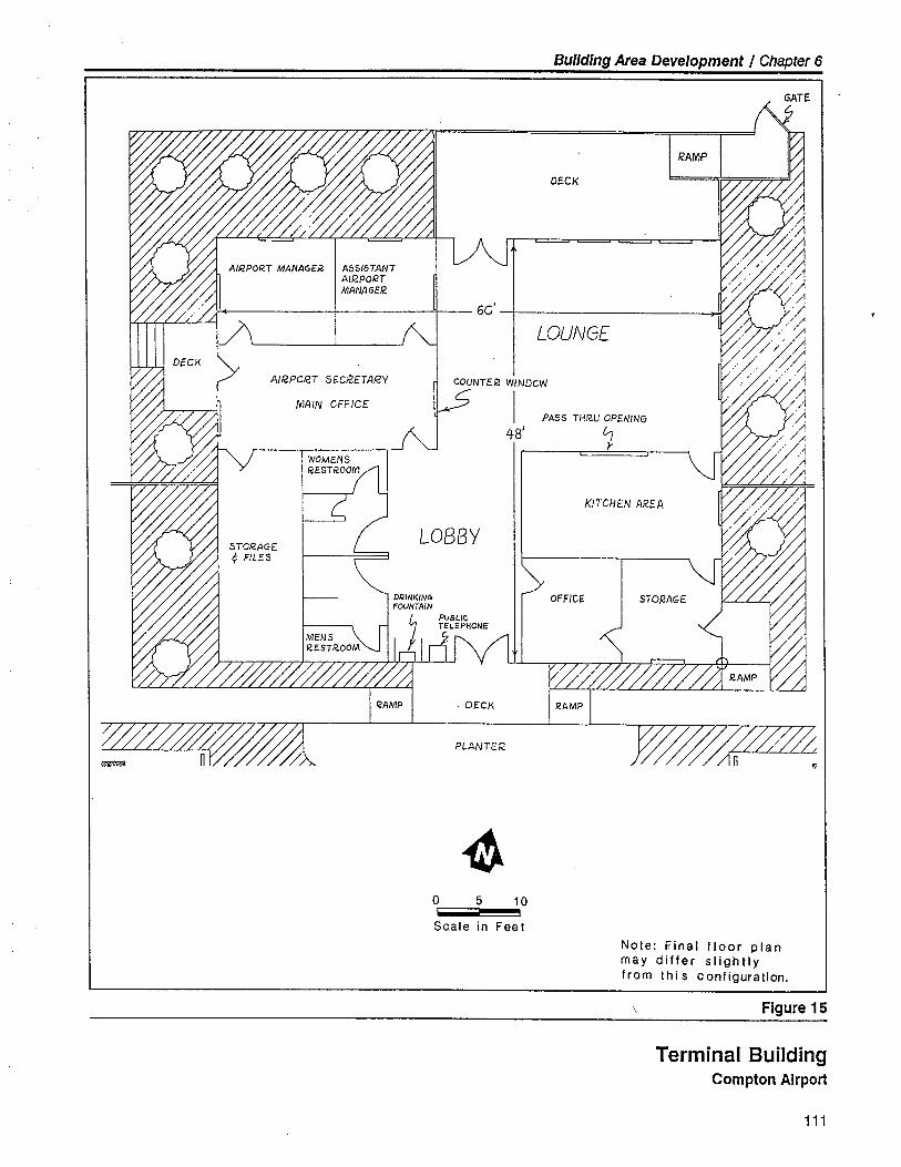
Building Area Development I Chapter 6
ASSISTANTAiR-PORTMANAGEI2
60'
AIR.PCR.T S£CR.£TAf2Y CQUNTE.2 WINDCW~ i48'
MAIN CFFJCE
LOBBY
. DEC¡~m7~--~ n WW/Ä. PLANTER.
~o 5
Scale in Feet
I2AMP
DECK
LOUNGE
PASS THR.U OPE.NING
7
KITCHEN AREA
10
Note: Final floor planmay differ slightlyfrom thi s configuration.
Figure 15
Terminal BuildingCompton Airport
111
Building Area Development I Chapter 6
As aircraft access to the facility is not required, a site located apart fromthe Airport's prime aircraft operating areas might be acceptable.
The existing airfield maintenance facilities are well located in this regard.Although the present facilities are somewhat oversized for current airfieldmaintenance needs, the excess capability can be leased out for revenue-producing activities. For example, the office portion of the maintenancebuilding could be used for an aeronautical-related activity such as anaircraft insurance broker's office or supplemental office/storage area forthe terminal building.
To permit the possible future expansion of the auto parking area in thevicinity of the terminal and airfield maintenance facility, it is suggestedthat the County acquire the auto service station in the northwest cornerof the Alondra Boulevard and Wilmington Avenue intersection. Theacquisition of such an old auto service station with underground fuelstorage tanks is potentially fraught with economic and environmentalliabilities. Any such acquisition should be based on a careful analysis ofthe associated cost/benefit implications and potential liabilities.
Fixed Base Operations Area
The Airport's three fixed base operators (FBO) are currently grouped inone area - the Airport's south central side. The existing FBO facilities(three 8,000 square foot conventional hangars with attched offices/shops)are in good condition and are well located on the Airport. Adequateparking for aircraft and customer vehicles is available adjacent to thehangars. It is anticipated that the existing three FBO hangars and attach-ed offices/shops will prove adequate to accommodate FBO developmentneeds over the 20-year planning period. Additional aircraft parking areain front of the FBO hangars is desirable to accommodate projected in-creases in aircraft size and numbers.
Aircraft Storage and Parking
As discussed in Chapter 4 - Airport Activity and Capacity Analysis, de-mand for based aircraft hangars and tiedown facilities at Compton Airportis projected to increase by an estimated 40% over the 20-year planningperiod. Aircraft owner surveys indicate that the large majority of theseaircraft would be stored under cover if suitable hangar space is available.In addition, tiedown positions, both taxi-thru and tail-to-tail configura-tions, should continue to be provided in sufficient numbers to accommo-date based and transient aircraft demand.
112
Building Area Development I. Chapter 6
Hangar Type and Size
There are 126 T-type fixed hangar units, one painting booth hangar, andthree conventional storage hangars (FBO hangars) presently located on
the Airport's south side. As noted previously, it is anticipated that de-mand for additional aircraft storage hangars will increase at ComptonAirport. It is suggested that future hangar development reflect: (1) userdemand; (2) physical siting and locational considerations; (3) based air-craft capacity considerations; and (4) funding resources.
The sizing of hangars can best be determined through a survey of poten-tial hangar users. Aircraft type, airframe dimensions, the nature of hangaruse (i.e., aircraft storage only versus workshop capability), facility sitingconsiderations, availability of adequate utilities (specifically water andelectricity), and market price largely determine the range of hangar sizesrequired to satisfy demand. Experience indicates that mid- to larger-sizedindividual storage hangars are highly preferred by users. T-hangars,whether portable or fixed, are most efficient in terms of apron area utili-zation. Rectangular or "box-type" hangar units are preferred by many
aircraft users but require more apron area for siting and are thus moreexpensive to rent. Frequently, rectangular or "box-type" hangars can be
used most advantageously along airport propert boundaries or in areaswhere taxiway access is only available on one side of the hangar com-plex. Such sites exist along the Airport's north perimeter walL. Largeconventional storage hangars are typically used by fixed base operationsor corporations operating several aircraft.
Hangar Location and Timing
In general, multiple-unit T-type fixed hangar development is more effi-cient on large, level reGtangular sites that can be committed to long-termhangar use. Portable T-hangars offer more siting flexibility and can belocated incrementally in smaller areas. In addition, the relative ease withwhich portable hangars can be relocated permits them to be sited inareas of the Airport that may be required in the long-term for an alterna-tive use. At some airport, private development of portble T-hangars is
encouraged to permit individuals the opportunity to own their hangars.This approach is frequently used at airport that are financially unable tofund hangar construction using internal resources.
Another hangar layout factor is the orientation of the buildings. Whenev-er practical, hangars should be oriented so the prevailing winds do notblow directly on the hangar doors. This orientation minimizes debris
accumulation in the hangars and makes hangar door operation less diffi-cult under windy conditions. At Compton Airport, strong prevailing windsare not a significant factor in orienting hangar buildings. Rather, theconfiguration of the existing buildings and the location of taxiway andtaxi lanes more directly influence hangar orientation.
113
Building Area Development 1 Chapter 6
The timing of hangar development should be based upon user demand,land availability, funding resources, and overall airport developmentstaging requirements. The hangar development plan must have sufficientflexibility to adjust to actual future requirements. Sites should be identi-fied for more hangar units than are expected to be required. The layout,though, should allow for incremental development with construction inadvance of demand being as limited as possible. Due to the anticipatedhigh future demand for additional hangar space, it is recommended thatreadily developable sites within the building area be identified and re-served for future hangar development. !n the interim, prime hangar sitescan be used as aircraft tiedown aprons to maximize Airport revenues andservice levels. It should be noted, however, that the FAA AlP grant re-quirements generally do not permit hangars to be developed on tiedownaprons funded by AlP grants.
Hangar Access
Aircraft storage hangars and based aircraft tiedown positions are bestlocated in areas of the Airport that require controlled or restricted access.By restricting public access to such areas, both safety and security aresignificantly enhanced. Only aircraft owners, pilots, passengers, andauthorized individuals would be permitted within the restricted area.This is the manner of security presently in effect at Compton Airport.Such control can be accomplished through the use of fencing/walls, con-trolled gates, signs, and surveillance. By providing a suitable number ofwell-located controlled access gates, authorized vehicular and personnelaccess to the aircraft hangar and tiedown areas can be assured. The fourcontrolled access gates currently in use at the Airport are well-located andoffer adequate user and emergency access to the airfield and buildingareas. It is suggested, however, that one additional controlled accessvehicle gate be provided in the southwest corner of the FBO area. Thisgate will facilitate authorized user access to the south side hangar area,helicopter operations area, and future airport traffic control tower.
Taxiway access from the aircraft storage and parking areas to the run-way/parallel taxiway system and within the building area is also veryimportant. Dead-end taxilanes and circuitous routings should be avoidedwhenever possible. Alternative taxiway routings configured to minimizehead-to-head traffic should be provided, particularly in high-volumeareas. In addition, breaks in the hangar rows should be provided topermit aircraft, vehicles, and personnel enhanced access between taxi-lanes. At Compton Airport, the need to maximize aircraft basing capacitywithin a very constrained land area substantially limits what can be rea-sonably accomplished in this regard. The desirability of such alternativetaxiway routings and hangar breaks must be balanced against the resultantloss in useable hangar capacity.
114
Building Area Development 1 Chapter 6
Tiedown Areas
An estimated 125 tiedown positions (based aircraft and FBO parking) areprojected to be required by the end of the 20-year planning period. Thisnumber is the same as the approximately 111 tiedown positions currentlyin use on the Airport, and reflects the projected increase in the availabilityand use of aircraft storage hangars.
Large, appropriately-oriented tiedown areas are preferable in that theypernìit simpler fencing, lighting, and access. However, due to the limitedland available at Compton Airport, tiedown positions can also be used tomake maximum efficient use of small or odd-shaped apron areas. Inaddition, paved areas of the Airport can be used for interim aircraft tie-downs until such time as the area is needed for another use such ashangar development or fixed base operations facilities.
In general, it is preferable for tiedowns to be oriented into the strongestwinds. This arrangement minimizes potential aircraft upset or controlsurface deflection damage. Although the lack of consistently strong windsat Compton Airport makes this factor somewhat less significant, it is desir-able for tiedowns to face west or east, wherever practicaL.
Hangar/Tiedown Area Siting Considerations
At Compton Airport, limited land availability and FAA design criteriacombine to constrain hangar and tiedown area development opportuni-ties. Figure 16 depicts the impact of FAA design criteria (e.g., FAR Part77 surfaces and Aircraft Parking Limit) on future hangar and tiedown areadevelopment. Ideally, all hangars should be sited so as not to penetratethe runway's Part ii transitional surfaces. However, some penetrationmay be desirable and acceptable to the FAA based on a facility-specificassessment of need and impacts. Such penetration may be appropriatefor hangar development along the Airport's north perimeter walL.
Helicopter Operations
Helicopter operations are playing an increasing role in Compton Airport'soverall activity. Master plan projections indicate that helicopter activitywill continue to increase in the years ahead - both in terms of basedhelicopters and helicopter operations. As noted in Chapter 4, the bulk ofthis helicopter activity will be generated by public-service helicoptersoperated by agencies such as the City of Compton Police Oepartmentand other nearby communities. In addition, helicopters operated by theAirport's fixed base operators, area businesses and corporations, andtransient helicopter operators will contribute to this increased activity.
Ideally, helicopter operations should be located away from fixed-wingaircraft operations. Helicopters and airplanes are somewhat incompatible
115
Building Area Development 1 Chapter 6
in that while they share the same airspace, they do so at different speedsand in different flight regimes. In addition, the downwash from a heli-copter's rotor blades has the potential to upset nearby fixed-wing aircraftand raise dust, dirt, and debris. For these reasons, it is generally desirable
to locate all helicopter activity in one location - generally apart fromfixed-wing aircraft activity. As an example, FAA design standards suggestthat a helipad at a tower-controlled airport be located at least 400 feetfrom the runway centerline if independent operations are to be permitted.
At Compton Airport, land constraints do not permit a high level of opera-tional separation. By physical necessity, helicopters and airplanes mustshare the Airport's facilities and airspace. This requires a measure offacility compromise and user coordination to jointly operate in a safe andefficient manner. Such compromise and coordination has been success-fully utilized in the past at the Airport and it is anticipated that futureshared use of the Airport can be beneficially accommodated in much thesame manner. However, strict operational procedures (e.g., designatedtraffic patterns, approach/departure corridors, traffic position reporting,user awareness, etc.) will be required to safely and efficiently accommo-date this activity.
Helicopter activity is currently concentrated on the Airport's south centralside. This location, while not optimum from a planning and operationalperspective, represents the best available location on the Airport. Thefactors contributing to this conclusion include:
· Near center of runway/taxiway system - permits helicopters to more
safely and efficiently fit in with fixed-wing aircraft traffic pattern.
· Central location enables helicopters to utilize runway/taxiway corridorsfor low-level approaches and departures (i.e., facilitates translationallift operations).
· Remote from terminal area and fixed base operations area - minimiz-es rotor downwash impacts.
· Remote from noise-sensitive single-family residents (i.e., predominantlythose to the north side. of the Airport).
· Existing commitment to helicopter facilities in that area.
· Space and facilities are available to accommodate based helicopterneeds (i.e., utilize existing area T -hangars and former paint hangar forhelicopters) .
· Proximate to primary area access roads and visible to public (i.e.,enhances Airport security and presence in the local community).
· Location within controlled area facilitates enhanced security and safe-
ty.
116
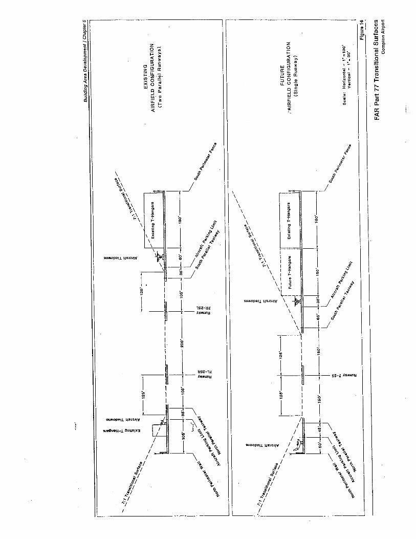
-"...
.. ~
I!
II
I i'i
'i\e
.C8,
...
.,'1 .,
i-;=
;=S~
, ./
to(\
e.'./
./..
~~
/II~
;¡~
ø"'O
..
.. l:IIIS
..e
i!,,,
e: ./
;¡1;
;./ ..
..~~C
eO
J;¡
;¡
--"-, 1"'.-
i''''~
//".
".E
XIS
TIN
G".
Exi
stin
g T
-Han
garø
il
AIR
FIE
LD
CO
NFI
GU
RA
TIO
N,
~---
==
"./-
-(T
wo
para
Jl~J
Run
way
sl--
---""
--L
106.
_LJ-
106'
-120
0'L 106J36'160.--
160'
I
) ,.,~
)I
I~~
~~
.\\ ~
\' ...
'1~
ir~
..&
'O(¡
t¡¡
Alr
Cr4
'I:oS
.. '"
.. '"
""'4
A
~
,,\ 1
-\P
Pø
,ø \,
,~ ~
'\..
Aii 1 A
"rl.
~ø(\
G' ~
.(~
..\\Ø
ir ~
ir g
:rilll. 4'rll
11..1
,,, ." ~~
"I., "g
"r t:
~O
l t-\
(c,(
~o(
'''Il--l (1111
e"C
e"'il;. 1
Bui
ldin
g A
rea
Dev
etop
men
t I C
hapt
er 6
".~
-- / /~ ~ ~/,.
~ ~ s~\/
'0 '0
,\'O
(\~
-...~"1 .. i-.! tD 'ò' ,/
..'r. ¡: "",0-(\/
..118
1,1
1"\ .
... 0114'1 'E ~ ;-"/
.. ..
8(Jr
lll e
e /
/..
ce :ë
~ /
..'...
...~
-12
6'-j1
26'l
//f.:-
----
----
lilt ~ I / / I Fulure T-Hangara
l~I ''¡':_____= _____---- i i
L6O
l4J_
160'
_1_1
50'-1
-65.
--.3
J_15
0'~
))) I ~ l.
"'6\
\ ",\~
\\. \-
-6"
~ &
'°lJ
t Alr
Cr
0\.8
' \(\
~ .
"\ 6
-J ,!
~ .o
qr ii
,; p
nøt\Go "'6t~ 6\,6' ~ ii//fii "rli
~ '
.'\ ~
.( ..
., "
g (
~ot\; tt'tct ft\'-- ~ 4'-t/ko 1111
.'(0
£. "
.. ;
Exi
stin
g T
-Han
gars
FUT
UR
E
,''A
IRFI
EL
D C
ON
FIG
UR
AT
ION
(Sin
gle
Run
way
)
IBO
'I l.
80(J
; "A"a
11'"
"r t:
fil)
C~
Scale: Horizontal - 1- = 1 00'
V"rtlcal - l =' 30'
i:lgu
!~
FA
R P
art 7
7 T
rans
ition
al S
urfa
ces
Com
plon
Airp
ort
Building Area Development 1 Chapter 6
· Utilities are readily available.
The principal disadvantage of this centralized location is the proximity ofthe helicopter operating area to the primary south side parallel taxiwayand adjacent fixed-wing aircraft hangar areas. This proximity wil necessi-tate that helicopter a'nd fixed-wing aircraft operations be dependent uponeach other and operationally interrelated. While this interdependency isnot generally desirable, it represents an operational compromise requiredby the Airport's constrained land area. When the Airport is reconfiguredinto a single runway configuration, approximately 100 feet of additionalapron depth will be available for expansion of the helicopter operatingarea. To provide additional room for the accommodation of helicopterground operations, two or three of the existing T-hangar buildings in thesouth central area could be removed or relocated. This action wouldfacilitate the use of the airspace overlying the Alondra Boulevard right-of-way as a helicopter approach/departure corridor.
To facilitate business and personal helicopter users' access to the terminalbuilding, transient helicopter parking pads could be located in the apronarea between the aircraft fueling facility and the airfield maintenancefacility. All based helicopter users should be encouraged tohangar/tiedown their helicopters in the vicinity of the established southcentral helicopter operating area.
Alternative locations for helicopter operations and facility developmentwere considered as part of this analysis. These alternative locations in-cluded:
- In the southeast corner of the Airport
- To the east side of the fixed base operations area
- On the north side of the Airport- In the northeast corner of the Airport - across Wilmington Avenue
from the proposed City of Compton Police Department neighbor-hood station
- Off-airport adjacent to the Airport's northern boundary
The alternative location in the southeast corner of the Airport receivedspecial consideration as part of the master planning process. This areahas been identified in the past as being a possible location for concentrat-ed helicopter operations. An analysis of the advantages and disadvantag-
es associated with these two alternative locations (Le., south central siteand southeast site) is provided in Table 12.
A study team of airport planners, experienced helicopter operations spe-cialists, and FAA air traffic control representatives contributed to thisanalysis of helicopter operations facility siting alternatives. This analysisconcluded that the south central location is superior to all other on-air-
port alternative locations. Oevelopment of the south central area forconcentrated helicopter operations is depicted in the Airport Layout Plan(see Chapter 2-Figure 1).
117
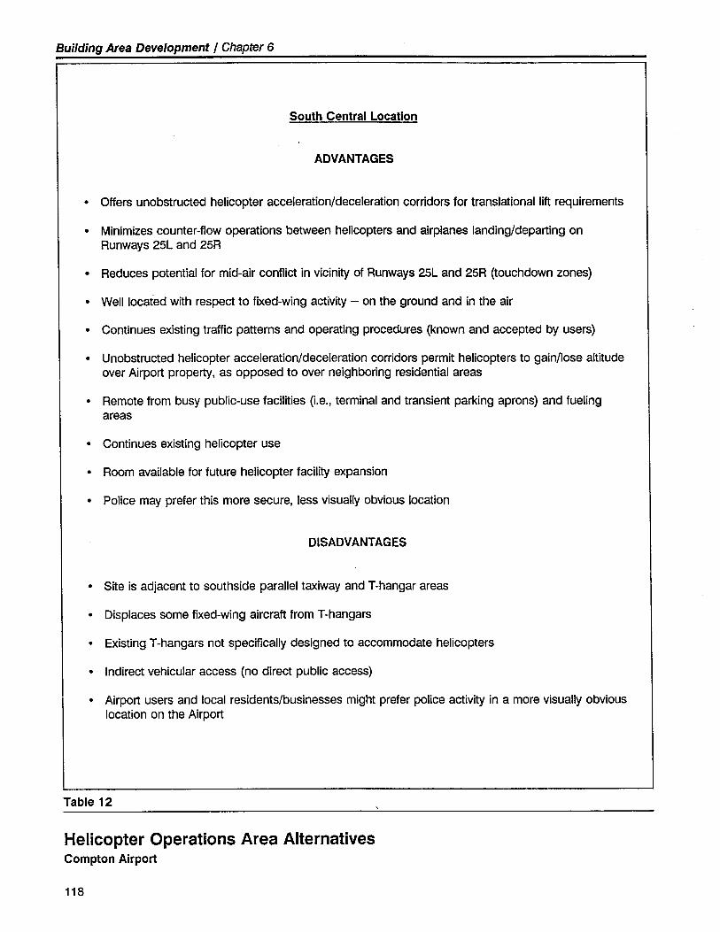
Building Area Development / Chapter 6
South Central Location
ADVANTAGES
· Offers unobstructed helicopter acceleration/deceleration corridors for translational lift requirements
· Minimizes counter-flow operations between helicopters and airplanes landing/departing onRunways 25L and 25R
· Reduces potential for mid-air conflict in vicinity of Runways 25L and 25R (touchdown zones)
· Well located with respect to fixed-wing activity - on the ground and in the air
· Continues existing traffic patterns and operating procedures (known and accepted by users)
· Unobstructed helicopter acceleration/deceleration corridors permit helicopters to gain/lose altitudeover Airport propert, as opposed to over neighboring residential areas
· Remote from busy public-use facilities (Le., terminal and transient parking aprons) and fuelingareas
· Continues existing helicopter use
· Room available for future helicopter facilty expansion
· Police may prefer this more secure, less visually obvious location
DISADVANTAGES
· Site is adjacent to southside parallel taxiway and T-hangar areas
· Displaces some fixed-wing aircraft from T-hangars
· Existing T-hangars not specifically designed to accommodate helicopters
· Indirect vehicular access (no direct public access)
· Airport users and local residents/businesses might prefer police activity in a more visually obviouslocation on the Airport
Table 12
Helicopter Operations Area AlternativesCompton Airport
118
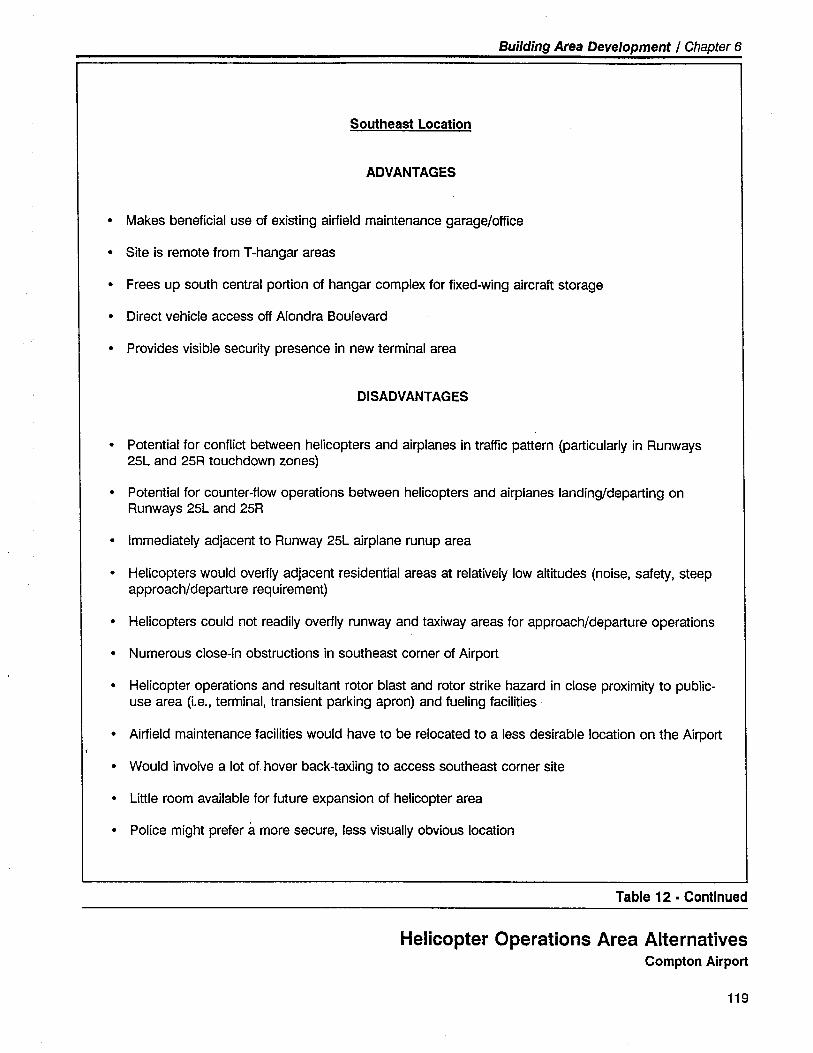
Building Area Development / Chapter 6
Southeast Location
ADVANTAGES
· Makes beneficial use of existing airfield maintenance garage/office
· Site is remote from T-hangar areas
· Frees up south central portion of hangar complex for fixed-wing aircraft storage
· Direct vehicle access off Alondra Boulevard
· Provides visible security presence in new terminal area
DISADVANTAGES
· Potential for conflict between helicopters and airplanes in traffic pattern (particularly in Runways25L and 25R touchdown zones)
· Potential for counter-flow operations between helicopters and airplanes landing/departing on
Runways 25L and 25R
· Immediately adjacent to Runway 25L airplane runup area
· Helicopters would overfly adjacent residential areas at relatively low altitudes (noise, safety, steepapproach/departure requirement)
· Helicopters could not readily overfly runway and taxiway areas for approach/departure operations
· Numerous close-in obstructions in southeast corner of Airport
· Helicopter operations and resultant rotor blast and rotor strike hazard in close proximity to public-use area (i.e., terminal, transient parking apron) and fueling facilties.
· Airfield maintenance facilties would have to be relocated to a less desirable location on the Airport
· Would involve a lot of hover back-taxiing to access southeast corner site
· Little room available for future expansion of helicopter area
· Police might prefer á. more secure, less visually obvious location
Table 12 . Continued
Helicopter Operations Area AlternativesCompton Airport
119
Building Area Development / Chapter 6
Airport Traffic Control Tower
Compton Airport is the sole remaining public-use airport in the Los An-geles basin that is not equipped with an operating airport traffic controltower. The possibility of establishing such a facility at the Airport hasbeen discussed from time to time over the past several years. A numberof years ago, an area of land on the Airport's north side was acquired bythe County for the siting of an airport traffic control tower. However, thecontrol tower was never installed.
As part of this master plan, the need for a control tower at ComptonAirport was explored. The Federal Aviation Administration, the federalagency responsible for funding the construction and operation of virtuallyall public airport traffic control towers, specifies minimum operationalactivity levels that airport must exceed in order to qualify for establish-ment of a federally-sponsored control tower. Generally speaking, theFAA requires that the benefits to be realized from the establishment andoperation of the control tower must exceed the cost to the government.
The initial test currently used by the FAA to identify potential controltower sites is called the Phase I Tower Establishment Ratio. This test andits application to Compton Airport operational counts is presented inTable 13. It should be noted that the FAA is presently reviewing itscriteria for the establishment and discontinuance of airport traffic controltower facilities. It is anticipated that any new criteria will be based upona life-cycle assessment of costs (capital and operating) and benefits (safetyand efficiency). This approach is substantially the same as at present.
As noted in Table 13, on the basis of present and future operationalcounts alone, Compton Airport does not meet the minimum operationalactivity levels needed to qualify for a control tower. However, the FAAprovides that an airport may be exempted from meeting the Phase I testand be considered a candidate for establishment of a control tower be-cause of other special factors. In this case, a site-specific analysis must beperformed and adequate justification presented. The site-specific analysisshould include, but not be limited to:
· Assurance that factors unique to the location, such as weather andtopography, are properly accounted for.
· Impact on adjacent facilities.
· Operational factors which cannot otherwise be accounted for by thebenefit-cost analysis.
· Potential use of the site to provide capacity and training relief for ahub airport.
120
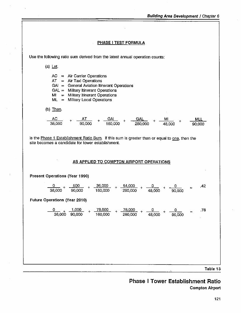
Building Area Development / Chapter 6
PHASE I TEST FORMULA
Use the following ratio sum derived from the latest annual operation counts:
(a) Let.
AC = Air Carrier OperationsAT = Air Taxi OperationsGAl = General Aviation Itinerant OperationsGAL = Miltary Itinerant OperationsMI = Military Itinerant OperationsML = Miltary Local Operations
(b) Then.
AC38,000
+ AT90,000
+ GAl160,000
+ GAL280,000
+ MI
48,000+ MLL
90,000
is the Phase 1 Establishment Ratio Sum. If this sum is greater than or equal to one, then thesite becomes a candidate for tower establishment.
AS APPLIED TO COMPTON AIRPORT OPERATIONS
Present Operations (Year 1990)
0 + 500 + 36.000 + 54.000 + 0 + 0 .4238,000 90,000 160,000 . 280,000 48,000 90,000
Future Operations (Year 2010)
0 + 1.000 + 78,000 + 78.000 + 0 + 0 .7838,000 90,000 160,000 280,000 48,000 90,000
Table 13
Phase I Tower Establishment RatioCompton Airport
121
Building Area Development / Chapter 6
. The possibility of significant changes in traffic activity attributable tounique local conditions.
· Military requirements.
Of particular interest and application at Compton Airport are the firstthree analysis factors. Any analysis of the need and justification for afederally-sponsored control tower at Compton Airport should consider thefollowing special factors:
. The airspace in the vicinity of the Airport is among the most complexin the world. Controlled Airspace, Terminal Control Areas, Airport
Radar Services Areas, Airport Traffic Areas, Victor Airways, TCA-Con-trolled Transition Routes, Instrument Approach Routes, Control Zones,and VFR flyways are all located in the immediate vicinity of ComptonAirport. Individually and together, these airspace components directlyimpact Airport operations. It is anticipated that this airspace environ-ment will become increasingly more complex in the years ahead.
. Compton Airport's proximity to Los Angeles International Airport (8statute miles), Hawthorne Municipal Airport (5 statute miles), LongBeach Airport (6 statute miles), and Torrance Municipal Airport (7statute miles). All of these airport generate considerable VFR and IFRaircraft activity that has the potential to interact with aircraft operatingto/from Compton Airport.
. Marginal VFR flight conditions, generally due to urban smog, are prev-alent in the central Los Angeles basin. Low in-flight visibility andcloud ceilings strain the practical utility and safety of the "see and beseen" visual flght concept.
. Nonstandard traffic patterns (i.e., right-hand patterns for Compton'sRunways 7L and 7R and left-hand pattern for Runway 25R) are in useat Compton Airport as a result of the Airport's proximity to Los AngelesInternational Airport and Hawthorne Municipal Airport instrumentapproach routes. The nonstandard patterns concentrate flight activityto the south of the Airport and increase the potential for inadvertent
"head-to-head" aircraft operations on the downwind leg.
Consideration of these special factors indicates that a control tower maybe warranted at Compton Airport at some point within the 20-year plan-ning timeframe. Accordingly, a suitable site for the installation of anairport traffic control tower is indicated on the Airport Layout Plan. Theproposed site is centrally located on the south side of the airfield, offerssatisfactory line-of-sight over all airfield operational areas, and does notvisually interact with neighboring residential areas. It should be notedthat the preferable site from an operational point of view - the previouslyacquired site on the Airport's north side - is not considered viable due tothe local residential community's negative reaction. The exact siting,timing and manner of implementation of the control tower should be
122
.J!
--j...1
Building Area Development / Chapter 6
'.. determined through a special detailed analysis similar to that recentlyperformed to justify establishment of the airport traffic control tower atWhiteman Airport.
,:1: !
..
FACILITY REQUIREMENTS - NORTH SIDE BUllDINC
An...KI:
Oue to space constraints and operational considerations, the majority ofthe building area development and use will occur on the Airport's southside. The Airport's north side, due to its shallow depth, lack of viableground access, and proximity to residential uses, offers somewhat lesspotential for extensive future development and use.
The north side of the Airport can, however, be beneficially used for thefollowing aviation support purposes:
· Compliance with airfield design setbacks and FAR Part 77 surfaces.
· Location for north side parallel taxiway - provides aircraft access to
north side building area and reduces congestion on south side paralleltaxiway.
· Location for based aircraft storage - primarily tiedowns and enclosedstorage in portble T-hangars and portable rectangular/box-type han-
gars.
· Location for based aircraft pilot's lounge/rest rooms, aircraft washingarea, owner-performed aircraft maintenance enclosure, and segmentedcircle/wind cone.
Aircraft Storage Hangars and Tiedowns
There are 38 T-type portble hangars presently located on the Airport'snorth side. In addition, there are approximately 100 available tiedownpositions - 85 of which are presently in use.
The shallow depth of the future north side building area (i.e., associatedwith the single runway configuration) only allows the development of asingle row of tiedown and/or aircraft storage hangars. Tiedowns offer themost aircraft storage capacity per lineal foot and are the most flexible interms of future facility use modification. Hangars, if installed in this area,would most beneficially be of the rectangular/box-type to permit maxi-mum utilization of available space. The hangars should be placed facingsouth with the hangars' back walls approximately 10 feet from the Air-port's north perimeter walL. This distance is required to meet local firecodes and to discourage persons from using the hangar roofs as a vaulting
123
Building Area Development / Chapter 6
platform from the perimeter walL. Approximately 60 45-foot x 40-footrectangular/box-type hangars can be accommodated in this area. Occa-sional breaks in the line of hangars will be necessary to permit inspection,cleaning, and fire response to the alley created between the rear of thehangars and the perimeter walL.
It should be noted that siting of hangars along the north side perimeterwall may require a design standards waiver from the FAA, due to thehangars' penetration of the Runway 7-25 7:1 transitional surface (seeFigure 16). The decision as to the allocation of tiedowns and hangars inthis area should be determined on the basis of user demand, cost/benefitconsiderations, and airport operational needs.
Aircraft Washing Area
Typical of seaside urban areas, Compton Airport's atmospheric environ-ment is hard on aircraft. Airborne salt, moisture, dust, dirt, and chemicalpollutants combine to quickly weather, age, and deteriorate aircraft air-frames, instruments, and powerplants. Frequent washing of aircraft isrequired to slow the deleterious effects of these caustic agents. An air-craft washing area, equipped with a multi-trap water/oil separator, hasbeen established in the northeast corner of the Airport. It is recommend-ed that this facility be retained in this area and expanded, if necessary, inthe future to accommodate demand. Oue to this area's proximity to thefuture Runway 25 holding bay/runup pad, operational procedures may berequired to mitigate the effects of runup propeller blast impacting aircraftwashing area users.
Owner-Performed Aircraft Maintenance Enclosure
It is suggested that a site for an owner-performed aircraft maintenanceenclosure be provided in the north side building area. The site should belarge enough to accommodate one to two aircraft within one or moreenclosures. In addition, the site should have electrical service, be acces-sible by aircraft owner vehicles, and be separate from fixed base opera-tions areas. A site in the vicinity of the aircraft washing area is preferable.An alternative site is in the northwest corner of the Airport near the Com-pass Rose. The enclosure should be an all-metal, three-sided, coveredshed with electrical'outlets, overhead lighting skylights, workbench, oilwaste disposal tank, and fire extinguishers. It is recommended that air-port management establish well-defined operating policies and schedulingprocedures covering the operation and use of this facility.
124
Building Area Development / Chapter 6
FACILITY REQUIREMENTS - OTHER
The following additional support facilities are suggested for developmentor improvement within the Compton Airport building area.
Airport Perimeter Wall
Approximately 60% of the Airport's perimeter is equipped with a 7-foot-high cinder block walL. This wall serves two primary purposes - it en-hances the security and safety of the Airport and the adjacent residentialuses, and it ameliorates aircraft noise impacts on adjacent off-airport landuses.
Extension of the wall along Alondra Boulevard to completely enclose theAirport has been proposed from time to time. The advantages and disad-
vantages of such action are as follows:
· Advantages
- Enhances airport security and safety- Ameliorates aircraft noise impacts on adjacent off-airport land
uses- Oiminishes visual impact of airport- Reduces effect of winds and gusts on nearby aircraft
· Oisadvantages
- Potential to be an eyesore due to graffiti on the outer wall sur-face
- Citizens may perceive the perimeter wall as further isolating theAirport from the local community
- Somewhat limits fire response access- Has potential to restrict public view and access to fixed base
operators and terminal area facilities
The Airport Layout Plan depicts the future extension of the airport perim-eter wall from the edge of the southwestern-most T-hangar building to thesouthwestern corner of the fixed base operations area. A fenced gap inthe wall near the intersection of Alondra Boulevard and Central Avenue isprovided to permit vehicular line-of-sight at the intersection. It is suggest-ed that there be no wall in the vicinity of the fixed base operations area
and the terminal area. This will facilitate public view and access to thesecommercial areas.
125
Building Area Development / Chapter 6
Fencing, Gates, and Lighting
The Building Area Plan identifies the security fencing, gates, and lightingrequirements appropriate to this category of general aviation airport. Thefirst level of security preparedness serves to prevent unauthorized person-nel and vehicles from inadvertently accessing aircraft movement areas andhazardous operating areas (e.g., fuel storage/dispensing facilities, airfeldmaintenance facility, etc.). The second level of security preparednessseeks to prevent the determined effort of unauthorized personnel andvehicles from gaining access to secured areas of the Airport. This level ofsecurity is appropriate for much of Compton Airport's airfeld and build-ing areas.
Typically, security preparedness at this second level requires the use ofthe following security equipment and techniques:
- Extensive chain link fencing/walls - airport perimeter and terminal
area- Controlled access gates - vehicle and personnel
- Warning and advisory signage- Vehicular identification program
- Airport-user awareness
- Ramp and facility lighting- Surveillance personnel and patrols
To facilitate authorized user access to the Airport's south side buildingarea (particularly the aircraft storage hangars, helicopter operations area,and future airport traffic control tower), an additional controlled accessvehicle gate is suggested for the southwest corner of the fixed base opera-tions area.
Airport Viewing Area
A highly desirable enhancement to any general aviation airport is theprovision of a publicly accessible airport viewing area. By providing localcitizens and aviation enthusiasts with a comfortble vantage point toobserve airport and aircraft activity, interest and support for the Airportare encouraged. Compton Airport presently offers two excellent locationsfor public viewing of Airport activity. These locations are: (1) the elevat-ed platforms between the fixed base operations hangars; and (2) theobservation deck on the airside of the new terminal building. These twolocations should be adequate for public viewing purposes.
\.
126
Building Area Development / Chapter 6
BUILDING AREA CONFIGURATION ALTERNATIVES
A number of alternative building area development configurations wereidentified and explored as part of the master plan study. The variousalternatives were carefully assessed by the consultant and County staffwith respect to the design factors, development issues and opportunities,and facility requirements identified in this chapter.
This analysis of alternatives resulted in the selection of the optimumbuilding area development plan depicted in the Airport Master Plandrawings (see Chapter 2-Figure 4). A tabular description of the aircraftstorage capacities associated with the optimum building area developmentplan is presented in Table 14. The selected configuration facilitates theorderly and cost-effective transition between the existing airport configura-tion and the ultimate 20-year configuration. In addition, the selectedbuilding area configuration permits a significant measure of flexibility inaccommodating aeronautical demand and adjusting to future changes ingeneral aviation service requirements.
BUILDING AREA STAGING PlAN
The building area development staging plan, as recommended in thisMaster Plan, is based upon the following planning and design objectives:
· Address, in an expeditious manner, those building area elements thatare required to enhance operational and public safety (e.g., provideadequate Object Free Areas and Runway Safety Areas).
· Coordinate building area modifications with runway/taxiway system
improvements, as required (e.g., anticipate future conversion of airfieldfrom parallel runway system to single runway configuration).
· Anticipate the requirement for building area improvements on thebasis of demand and not merely the passage of time (e.g., flexibility inthe development of new aircraft storage hangars).
· Implement, in a cost-effective and coordinated manner, the reconfigu-ration and improvement of the building area.
· Minimize, to the extent practical, inconvenience and disruption toairport user and tenant activities.
Oescribed in Table 15 is the recommended staging plan for the coor-dinated implementation of airfield and building area improvements. Asnoted previously, the scheduling of these improvements should be based
127
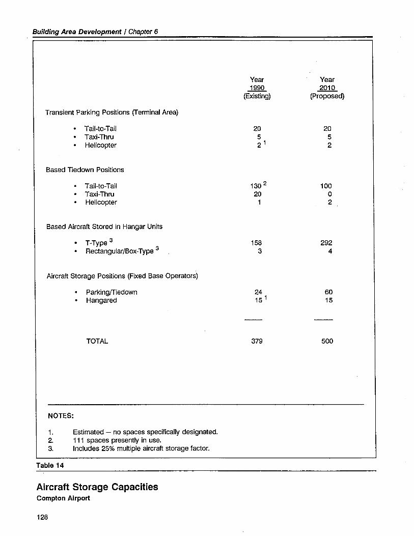
Building Area Development / Chapter 6
Year Year1990 2010
(Existing) (Proposed)
Transient Parking Positions (Terminal Area)
. Tail-to-Tail 20 20
. Taxi-Thru 5 5
. Helicopter 21 2
Based Tiedown Positions
. Tail-to-Tail 1302 100
. Taxi-Thru 20 0
. Helicopter 1 2
Based Aircraft Stored in Hangar Units
. T-Type 3 158 292
. Rectangular/Box-Type 3 3 4
Aircraft Storage Positions (Fixed Base Operators)
. Parking/Tedown 24 60
. Hangared 15 1 15
TOTAL 379 500
NOTES:
1. Estimated - no spaces specifically designated.
2. 111 spaces presently in use.
3. Includes 25% multiple aircraft storage factor.
Table 14
Aircraft Storage CapacitiesCompton Airport
128
Building Area Development / Chapter 6
upon anticipated demand and not merely the passage of time. Variationsin staging are possible as may be required by changing demand charac-teristics and/or the Airport's financial condition.
The capital cost estimates associated with the building area improvementsare identified in Chapter 8 - Financial and Implementation Issues.
129
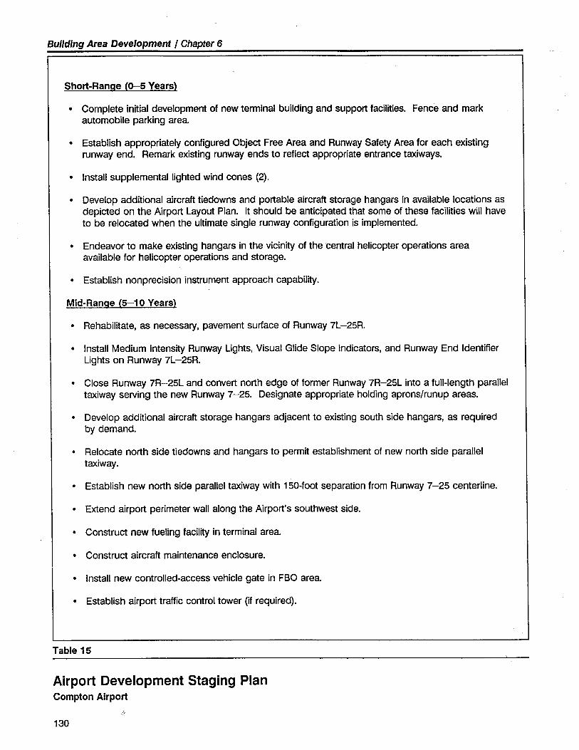
Building Area Development / Chapter 6
Short-Ranae (0- Years)
· Complete initial development of new terminal building and support facilities. Fence and markautomobile parking area.
· Establish appropriately configured Object Free Area and Runway Safety Area for each existingrunway end. Remark existing runway ends to reflect appropriate entrance taxiways.
· Install supplemental lighted wind cones (2).
· Develop additional aircraft tiedowns and portable aircraft storage hangars in available locations asdepicted on the Airport Layout Plan. It should be anticipated that some of these facilties wil haveto be relocated when the ultimate single runway configuration is implemented.
· Endeavor to make existing hangars in the vicinity of the .central helicopter operations areaavailable for helicopter operations and storage.
· Establish non precision instrument approach capability.
Mid-Ranae (5-10 Years)
· Rehabilitate, as necessary, pavement surface of Runway 7L-25R.
· Install Medium Intensity Runway Lights, Visual Glide Slope Indicators, and Runway End IdentifierLights on Runway 7L -25R.
· Close Runway 7R-25L and convert north edge of former Runway 7R-25L into a full-length paralleltaxiway serving the new Runway 7-25. Designate appropriate holding aprons/runup areas.
· Develop additional aircraft storage hangars adjacent to existing south side hangars, as requiredby demand.
· Relocate north side tiedowns and hangars to permit establishment of new north side paralleltaxiway.
· Establish new north side parallel taxiway with 150-foot separation from Runway 7-25 centerline.
· Extend airport perimeter wall along the Airport's southwest side.
· Construct new fueling facilit in terminal area.
· Construct aircraft maintenance enclosure.
· Install new controlled-access vehicle gate in FBO area.
· Establish airport traffic control tower (if required).
Table 15
Airport Development Staging PlanCompton Airport
..
130
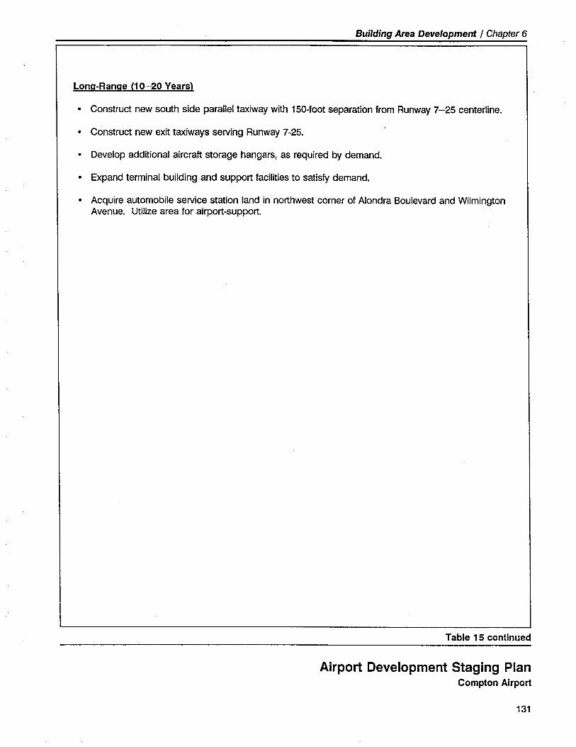
Building Area Development / Chapter 6
Lona-Ranae (10-20 Years)
· Construct new south side parallel taxiway with 150-foot separation from Runway 7-25 centerline.
· Construct new exit taxiways serving Runway 7-25.
· Develop additional aircraft storage hangars, as required by demand.
· Expand terminal building and support facilties to satisfy demand.
· Acquire automobile service station land in northwest corner of Alondra Boulevard and WilmingtonAvenue. Utilze area for airport-support.
Table 15 continued
Airport Development Staging PlanCompton Airport
131

._~.~~:"':..~.....L"_~,:..:~~~_:.~.","." . ---"-',I:"_.....-.;_...~"'...-~~- -.'-~'~. _. "..::',,"_.--'___:7__.
132
:"....;':',:..;,.
flLand Use .
andEnvironmental
Issues
..I
Land Use and EnvironmentalIssues
OVERVIEW
Over the years, extensive urban development has occurred in the areasurrounding Compton Airport. This off-airport urban development isprimarily composed of single- and multi-family residences, and commer-cial/industrial uses (see Figure 17). Despite the potential for incompati-bility and conflict between the Airport and certin of these off-airportland uses, particularly the single- and multi-family residential uses, theAirport and surrounding community have coexisted over the years inrelative harmony. To maintain and improve upon this positive relation-ship between the Airport and its neighbors, further land use incompatibili-
ty must be avoided and, where practical, existing land use incompatibilitymitigated.
This chapter of the master plan study examines the nature and extent ofoff-airport land use impacts related to Compton Airport operations.Established compatibility preservation measures are then reviewed. Fol-lowing these sections is a discussion of airport-specific land use compati-bility concerns and proposed impact mitigation actions. An Initial Studyof airport environmental impacts, prepared in accordance with the Cali-
. fornia Environmental Quality Act, is presented in Appendix E.
LAND USE COMPATIBILITY CONSIDERATIONS
The principal land use impacts and compatibility considerations associat-ed with the operation of a busy general aviation airport, such as ComptonAirport, fall into the following four major categories:
· Noise Impacts - Usually perceived as the most significant adverseimpact of airport activity. Noise impacts can be defined in terms ofaverage noise exposure levels and maximum single-event or intermit-tent noise levels. Average noise exposure levels are generally
133
Land Use and Environmenfallssues / Chapter 7
Noise impact mitigation tech-niquestypically include pilotawareness/education, flight trackadjustments, aircraft type restric-tions, airport operating hoursrestrictions, and airfield configu-ration modifications.
134
described in terms of noise contours. The descriptor used in Califor-nia to measure noise generated by airport activities is the CommunityNoise Equivalent Level (CNEL). Single-event or intermittent noiselevels are related more to individual aircraft overflights and are de-scribed in terms of decibel levels, which are adjusted to reflect thenormal range of human sound perception (dBA).
· Hazards to Flight - Hazards to flight are physical obstructions to thenavigable airspace (e.g., tall objects) and include other land use char-acteristics that could affect flight safety (e.g., distracting lights, smoke,electromagnetic interference, birds attracted by certain activities, andthe availability of suitable emergency landing areas underlying close-inapproach/departure zones).
· Safety on the Ground - The objective in providing safety on theground is to reduce the risk of damage or injury to persons or properton the ground in the event of an aircraft accident. The issue of safetyis most critical within the approaches to an airport where aircraft aremaneuvering below standard traffic pattern altitude (usually 1,000 feetabove airport elevation). This impact is difficult to address because ofthe very low probabilties involved.
· Overfights - A more extensive, but less well defined impact relatesto aircraft overflights and established air traffic patterns. Aircraft over-flights generally extend beyond the typically defined noise contoursand safety impact zones. Overflight impacts are often characterized asannoying. The degree of annoyance can vary widely, according to thelistener's subjective viewpoint, but is generally related to the frequencyof occurrence, altitude, time of day, and visual impact of overflights.
CURRENT AND PROJECTED LAND USE IMPACTSAND COMPATIBILITY CONCERNS
The impact that airport operations may potentially have upon surroundingland uses is determined by the configuration of the airfeld and associatedflight patterns, the type and volume of air traffic, and by the underlyingland uses. In this regard, it is anticipated that Compton Airport will, forthe next 10-15 years, continue its present role as a parallel-runway, pub-lic-use airport catering to single- and multi-engine general aviation aircraftweighing less than 12,500 pounds. During the latt part of the 20-yearplanning period, it is projected that the existing parallel runway configura-tion will be supplanted by a single runway based on the present align-ment of Runway 7L-25R. The Airport's traffic mix is not expected to besignificantly different from the present. The 20-year Master Plan forecastprojects only a modest increase in the level of airprt activity. The nature
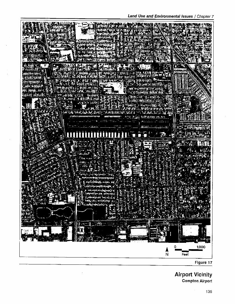
Land Use and Environmental Issues / Chapter 7
Â
N
o 1,000
Feet
Figure 17
Airport VicinityCompton Airport
135

Land Use and Environmental Issues / Chapter 7
and extent of the current and projected impacts associated with aircraftoperations at Compton Airport are summarized below.
Noise Impacts
Noise can be described as an unwanted or disruptive sound. Two basicelements determine whether a sound is perceived as disruptive: (1)characteristics of the sound itself; and (2) the human activity taking placewhen the sound occurs. The type of human activity is a factor in deter-mining the disruptiveness of a noise. A noise which may intrude uponone type of activity may be acceptable with respect to another. Variousstudies have been performed to determine the decibel level at whichnoise wil interfere with a given activity. This information has been usedto establish relationships between acceptable or unacceptable noise levelsand specific types of land uses.
At the time of this Master Plan study, comprehensive CNEL noise con7tours had not as yet been prepared for Compton Airport. A limited anal-ysis of noise contours at Compton Airport was performed in 1972. Thisanalysis, prepared by the Northrup Corporation for the Los AngelesCounty Board of Supervisors, identified only the 70 CNEL noise contourfor the years 1972, 1975, and 1980. It is strongly recommended thatnew CNEL noise contours be generated to reflect present operating con-ditions, as well as projected future operating conditions. CNEL noisecontours for Compton Airport - both for present and future activity levels- should be generated as an integral element of any upcoming Los An-
geles County Airport Land Use Plan. The resultant noise contours canthen be utilized to more accurately identify and define the extent of noiseimpact and to develop appropriate noise impact mitigation actions.
Hazards to Flight
As noted previously, two types of potential hazards to flight operationsare of concern: (1) physical obstructions to the navigable airspace; and
(2) other land use characteristics that can affect flght safety. Physical
obstructions to navigable airspace can include trees, pole lines, buildings,antennas, and terrain. Other land use characteristics that may affect flightsafety include: visual hazards such as distracting lights, glare, and sourcesof smoke; electronic interference with aircraft instruments or radio com-munications; uses which may attract flocks of birds; and the availability ofsuitable emergency landing areas in the Airport's close-in approach anddeparture zones. To safeguard an airport's present and future safety andutility, such potential hazards to flight operations must not be permittedto be established within the vicinity of the airport. '
The Federal Aviation Administration has established standards that identifyand define potential hazards to flight. Standards for the identification of
136
Land Use and Environmental Issues / Chapter 7
maximum allowable heights for structures and other objects are set forthin Part 77 of the Federal Aviation Regulations and, to a certin extent,
Advisory Circular 150/5300-13, "Airport Design." Limiting the height ofobjects and structures in the vicinity of an airport to below those heightsindicated by Part 77 surfaces provides an ample margin of safety fornormal aircraft operations. Deviation from the Part 77 standards does notnecessarily imply a safety hazard. It does mean, though, that the offend-ing objects must be evaluated by the Federal Aviation Administration. In
its evaluation, the FAA will indicate if the offending object is or is not anobstruction to air navigation. If it is an obstruction, the FAA may suggestremoval, obstruction lighting, aircraft flight path modification, airportoperation restriction, or some other form of impact mitigation. The actualmitigation action is the responsibility of the airport owner or local landuse controlling agency. The FAA has no power to directly require thatthe obstruction be removed or its impact mitigated.
The most critical areas with regard to flight hazards are within the ap-proaches to the Airport's runways. The approaches are defined by imag-inary surfaces which slope upwards from a point near the physical end ofthe runway. The imaginary surfaces for Compton Airport are illustrated inthe Airspace Plan developed as part of this Master Plan (see Chapter 2 -Figure 3).
At Compton Airport, the extensive development of the land areas under-lying the Airport's Part 77 approach surfaces has resulted in numerousbuìldings, antennas, fences, poles, walls, trees, and streets that have thepotential to be considered as obstructions and hazards to flight. Of par-ticular concern in this regard is the Compton Court Complex buildinglocated approximately 4,200 feet northeast of the Airport. This tall 13-story structure (approximately 156 feet above ground level) penetrates theAirport's FAR Part 77 horizontal surface and is considered an obstrlictionto air navigation. As such, this structure should be appropriatelymarked/lighted as an obstruction and noted on airport operational/trafficpattern diagrams. .FAA design standards permit the establishment of a displaced threshold toameliorate the effects of obstructions in the Part 77 approach surfaces.This is the design rationale utilized in part to locate the displaced thresh-olds for Compton Airport. Accordingly, it is recommended that the Air-port's runway threshold displacements be maintained as at present toensure adequate approach clearance over existing obstructions. TheAirport's existing displaced threshold locations provide greater thresholdplane clearance (i.e., approximately 26:1 for Runways 7L and 7R andapproximately 38:1 for Runways 25L and 25R) than that required by FAAdesign standards (i.e., a minimum of 20:1).
Action should be taken by the County and the City of Compton to ensurethat no further obstructions or hazards to flight are permitted within theareas defined by FAR Part 77. The specific means are discussed in subse-quent sections of this chapter.
137
Land Use and Environmental Issues / Chapter 7
Safety on the Ground
The approach zones are the most critical areas of the airport environs interms of the risks to people and structures on the ground. The loweraltitude of aircraft within the approach zones presents greater risks be-cause pilots have less opportunity to recover from unexpected occurrenc-es or make an emergency landing if one becomes unavoidable. At alti-tudes less than 500 feet above the ground, only moderate turns are advis-able and the choice of emergency landing area is essentially limited towhat lies ahead. Above this altitude, recovery or at least fairly widediscretion in choice of landing sites is possible. An emergency landing onthe runway normally can be accomplished when the aircraft is flying inthe traffic' pattern at the designated traffic pattern altitude (approximately1,000 feet above the airport elevation).
The other areas of interest in this regard are along the most commonflght tracks for aircraft approaching and departing the airport. Accidentsoccur relatively infrequently in these areas, however, and the probabilityof occurrence in any given location is substantially less than within theapproach zones.
Overflight Impacts
Compared to the preceding airport land use compatibility considerations,the annoyance factor of airport activity is more subtle and subjective.Overflight impacts arise in locations where neither noise nor safety ismeasurably a significant factor - the noise of aircraft overflights seldomdisrupts people's activities and the risk of an aircraft accident is statistical-ly very low. Moreover, the degree of perceived annoyance varies widelyfrom individual to individual, even though the definable impacts may besimilar.
Each individual's unique reaction to aircraft overflights may result from acombination of noise and safety concerns with fear being a subtle ele-ment of the equation. Although people generally do not fear aircraftnoise itself, they may be fearful of an aircraft crashing on their propert,and it is primarily the noise that creates their awareness that aircraft areoverhead. The extent to which different individuals react to overflightappears to be strongly influenced by their understanding of how airplanesfly, their attitude towards aviation, their knowledge of when and howoften overflights occur, as well as by the actual noise levels, time of day,and the altitude of the aircraft.
A policy implication of this impact is the importnce of public education.Owners of propert near an airport should be madè aware of the natureand extent of the airport's activities and the community's plans for futureairport development. The identification of common flight paths and the
138
Land Use and Environmental Issues / Chapter 7
distribution of aircraft activity are therefore importnt factors in the analy-sis of land use compatibility and application of mitigative techniques.
Compton Airport's overflight impacts are generally concentrated along the
typical flight tracks as shown in Figure 18. It is importnt to recognize,however, that overflight impacts can also occur in any part of the airportvicinity where aircraft fly at or below the standard traffic pattern altitude(1,000 feet above the Airport) while approaching or departing the run-way.
Due to prevailing winds from the west, the highest level of aircraft activityat Compton Airport is on Runways 25L and 25R. Compton Airport oper-ational personnel estimate that 90% of the takeoffs and landings occur onRunways 25L and 25R and 10% occur on Runways 7L and 7R. Runways
25L and 25R are formally designated as the calm/preferential runways.The current availability of VASI and REIL visual approach aids servingRunway 25L further encourages use of Runway 25L - particularly duringhours of darkness.
Generally speaking, larger aircraft (e.g., twin-engine and small jet aircraft)will approach or depart the runway in a straight line or a wide pattern,while the approach and departure patterns utilized by smaller aircraft aremore likely to remain within one mile of the Airport's runway. The Air-port's non-standard (j.e, right-hand traffic pattern serv'ing Runways 7R and7L) results in virtually all of the Airport's pattern traffic being located tothe south side of the Airport.
Historically, the Airport has received very few aircraft-related noise com-plaints from area residents. The few complaints which are received areusually associated with a distinct, atypical event (e.g., unusually loudaircraft departure at night).
ESTABLISHED LAND USE COMPATIBILITYMEASURES
Local land use plans, as well as municipal zoning ordinances and com-munity planning policies, are the principal means used to protect mostgeneral aviation airport from incompatible surrounding development.Compton Airport is owned and operated by the County of Los Angeles.However, it is the City of Compton which has the authority over land usein the area surrounding the Airport. Therefore, the City of Compton isprincipally responsible for the regulation of land use to assure the safe
and compatible development of propert in the vicinity of ComptonAirport.
In 1963, the City of Compton adopted the Compton General Plan. Thisplan suggested appropriate definitions, locations, and dimensions for land
139
Land Use and Environmental Issues . / Chapter 7
uses in the vicinity of Compton Airport. The 1963 plan concluded thatexisting physical limitations at the Airport necessitated the relocation ofthe Airport to a new site in the southern area of the City. However,action to relocate the Airport was never taken. The Compton GeneralPlan is currently being reviewed and extensively revised by the City ofCompton.
The existing, and admittedly out-of-date, Compton General Plan does notspecifically consider airport compatibilty in its designation of land uses.As a result, intensive incompatible development (i.e., high-density resi-dential uses) has surrounded the Airport. Little land remains available forfurther development and the likelihood of achieving the desired level ofland use compatibility is now very limited.
It is recommended that the new Compton General Plan (currently beingrevised) be formatted in a manner which permits the adoption of thefindings and recommendations which will resúlt from the Compton Air-port element of the Los Angeles County Airport Land Use Plan.
lAND USE CONTROLS AND IMPACT MITIGATIONTECHNIQUES
In the light of the factors noted above, several land use compatibility
concerns impacting Compton Airport and its environs must be addressed.Appropriate land use controls are required. The City of Compton is thelocal agency empowered by the State to ensure that appropriate land usecontrols are implemented in the vicinity of the Airport. Most important isthe need to ensure that further incompatible development does not occurwithin the Airport's two Runway Protection Zones (RPZ) and approach/transitional corridors. Additional concerns involve aircraft overflight ofareas located beneath the airport traffic pattern.
Airport Land Use Plan
State law requires that every California county where there is a public-useairport must establish an Airport Land Use Commission (ALUq. State lawcurrently designates the Los Angeles Regional Planning Commission as theALUC for Los Angeles County. Legislation enacted in 1989 (Senate Bill255-Bergeson) mandates the preparation of an airport land use compati-bility plan for each airport located in Los Angeles County. This legislativerequirement will result in the development of a "comprehensive land useplan" for the area around Compton Airport. Although this requirement iscurrently being reviewed by the state legislature, it is anticipated that anairport land use compatibility plan for Compton Airport may be preparedby the County at some point in the future.
140
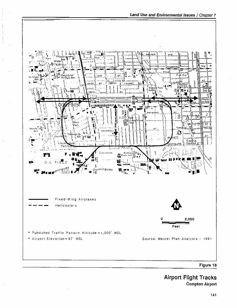
Land Use and Environmental Issues / Chapter 7
. ~..~.'. v " ,\' ~ if '\ ':' i' 11\ \b~~!Jrr, 7.-; . ""''''='=-''lr'T''~~=ir= ¥:È'==~iï'====ll'~='''ll'='== =-C==-'J~I
_. ......: \ ,APi' ,\ \,/'lrr¡, \¡'--J'i ITlhh~I..,.... r"'J'l"~'='~'i"=.\,,,L.e.A~~t;R,,....JL,"y~.-J~\ ~I~~. :.'Pa'k ," ion~er~::~=; , ~=,..... IISCh"'1jfm'.J\ \,::. ,====,1,==': ""1\ ..ir......il...--ìi~-.-:J\ '"
- : ,'.:~ï, wa1eN~ _i ,) _,\' ~=-.:=-~ \1' . :L . .., I l=,=J~.==l'====.= '~~(:j\"""=ï\i'='~'''\'i"O~rlJ- . i. "'\,~".rOllkS~... II . i ,l""~I\ ~="i L 11~ 1r " ",,=,=,=.=~=,=~i.,~~~--\t -~., , .. . "" _ -- -I -- _n Ir) 1\ ___il~'i --.--' _n__ -JL ir JL:J I,'" .' ,- :: '---'4---.1---\ a, C \"l'ON'..,. ." J -:,.-.,(":---11---' "''-''=-=r====j~_oMPaF--, " .:__\__~\. ii _ t-8 __ :lll~l_ _'I (.vßß.u~.._--L. :-' II_-!~~_~ t _, . I: -.,: : J.:' .-.e -,;.- irì ......... ~-l--""-l' 'I'~ M s~-- II - -" 168' I _.. -aL ~ '. .. r.. .~II Ji \ ¡ It L \\ -\ i ,. 1..1 ",,~ \:. __. PAl..wi l~ sr
I .1' : '~f:;r\' _i);==: F~l"rpri"" ~~, ~ ': ,.'~=h k /529 ~j¡ 'o'''~j\ ~';h~itigj ~ J~ - '";: osi1t~als '::': ~=="-r\ -~~f55\i~ :r~gi~:,:~ \ \ .~"i" J~\.~igh Sc.ii _I~ \ :._-.~~i- ~r.-_-. - ~'~L'_'_'_.~__~ i- _~_-_.-_'.~__ ~ ,..,~~\\. - ir:~"-"\t=~~-- -= \
' . ,I , i' i \1 \\ i ..... J' . ."-_i',,ii,el i; ..m.._,-...t 1'~'"'' \,. 'I.~~.:.::L~l.\ r5~~H i r ..\\I~ÙI'~.::~J".,H ~!;-:i:-~Chii +==~~~~..o=:\~ '''¡r:~ ~;~Z ,; ;:\f~~~~i'g1! Sch
..."..\'..1..' I' \ i . Ro"ch.¡ \ ....~' .......~ Ii Iii¡ 11____....._._J¡ 1VliOry,P"rk \, "-"\l ~Ú,/ .', .' \ '\~i_\.,Vr~-ll\,tA!~~H~!~:,:-~~;71~.,j\.J"J""SJ:::!~::':~~~~'::'=i" \, Sc _.\ 5ó 91;-,-;' i: \ Q';,' .:'?;~:..: \11 .\\ .\\ \r- i\ Ii .~\\ --~ I~ ... .-".-.,' ~'~ \\"2 ."', I 'Êi--::~='IC CID:::( , ,\\ l-JJ--~~c:i-io-J-- _~___.. ._
\\ \\ \\\ I.!WJl.w~!!ii'll!..~. CI _": 1:0"'=" - IÇ.\\ :¡ Ii \ \11 . ,\ 'i '\i . : "_'" -- ~8J ", .'I" .. i \~ \ i \ ~: I.. Ii\),. :j~ ')'i( á~D ~,; .'. ' .l:'.r. .j,i 1\ \1 ~ ~.frî\-i~"\\~- ii ~¡~f\~l:~1Yr-~'ND "'il '0' ~ har~S' "IC:\W-::¡".. . Ì' .- 'fò ",'("t() ii 'i il j:: fr,III.', a"" '~:et:
';-==-:T~-./Fr;i~ \\ '\~i" ~:r~ " ,,';~ í~~: :\1 i,l !I iI'tg -~!:,I\~ jh~nil\~ei¡\o '\1 Î~==' ~~ ".,.l:~ -=\\~,~01~,. ~lF~I¡
Hundt;."::" ~ \\ ,\ .~, ',\ \\ g" p~,l~\ r;~ _:. "" _n. ~\I !\ :\ \ \ 'i I, 'l~ ST II ~--bji~~B~-=dSoh -t \'., , ",:,:, i ,',', ".1 . (,"i' ì II \ \\ ÇALDWELLlJ. \\ 1\..1 =. I. '1..1~\¡=0~1 ,,- ",. . =. 'i: .= f' ,..-. ':W;.... J." ,.:' "/,C' ""'c'¡ "'iin I\n¡\ iI -î\ 9~!I " 'i ,ii iI 1\ I' ~L~,\~
5' ' ... "n/C~LD 'lJl''';,w~Si~I~..W''- -'.. 'i ..'-'1,.\1 i'l \~ \ \ 1 i , 'il TT '~\ ~\\~1'.-. . 1/-,/ ',i' 1" f 'II' : =- I i, ¡"i ' i \ ii \ I,: II BE ,",E-,,, ~~===I'\--'l.. :. /. ," ;', ". , \, .- ---": ..----,-.-.--, 'ii I'" II \1 \ \ i 1\ i :\ II Gag\r~\ .I'\ /,.: ':~ Li~~~~,( el\,'.: ;'1 I," ' I','' ',i I,' Ii 1\ I i I)¡ \ ~__i~P1i~'!;"~d~~'!--on~;=J1
i ,".iLi',...~___-_-~~~. S"i)"i"i,~,~..'----~\~:o~,~i~éi. . '?; ~~~2;;J . i':¡' ¡ .,.¡y"!' '. l,
~L F i ~: i :l~ ,::C::~',?.J 0 " ,;"''; ~i.~~;;l!!!! ~, - s., ï 1i==,":.,"":.' ! t-- d bn: '\. GUe"Z .j'.. 0 mingue II I. I:l' -. Ii' ,,,X "--- \.. _ ç0\0P\..,:::::::'.1 .' 0' Z "fi¡II¡,,, lo. L....ï,.. "'1' \,_ . '~. J 1,1-- _11I . E:::::;;o::.;':; ií T I _ . Ii
¥.
---- Fixed-Wing Airplanes
Helicopters ~0 2,000
i I
Feet
· Published Traffic Pattern Altitude =1,000' MSL
· Airport Eleva tion = 97' MSL Source: Mas i e r P I an A n a i y s i s - 1 9 9 1
Figure 18
Airport Flight TracksCompton Airport
141
Land Use and Environmental Issues / Chapter 7
ALUC's have authority only over new development within an airport'senvirons. ALUC's planning authority is further limited by the ability ofcities and counties to override the ALUC's recommendations. The limitedamount of additional development possible in Compton Airport's environsdiminishes the potential value of an ALUC comprehensive land use plan.However, it is recommended that the comprehensive land use plan forCompton Airport incorporate the land use compatibility measures identi-fied in the Airport Master Plan.
Land Acquisition
A relatively small portion of the land area encompassed by the Airport'stwo existing Runway Protection Zones is located within. airport propert(see Figure 193). The ownership of the land area encompassed byCompton's present and future Runway Protection Zones is identified inTable 16. The privately-owned land area within the Runway ProtectionZones is composed of a mixture of residential and commercial/industrialuse. The allocation of these uses is also identified in Table 16.
Virtually all of the private development within the Runway ProtectionZones is incompatible with FAA and State guidelines. Noise, safety onthe ground, safety of flight operations, and the requirement for heightlimits on structures and trees all contribute to this incompatibility. Theresidential land uses within both Runway Protection Zones are particular-ly undesirable in light of the high volume of aircraft overflying these areasat relatively low altitudes.
The fact is, however, that all of these land uses, including the residentialdevelopment, have coexisted with Compton Airpoit operations for manyyears. No major problems have arisen and few complaints have beenexpressed by residents and users of these areas. The County's decision to
provide greater than standard clearance in the approach zones has un-doubtedly contributed to this positive coexistence.
The Airport has been fortunate in that the proliferation of objects andobstructions (e.g., trees, utility poles, structures, etc.) in the vicinity of theAirport has not significantly diminished the safety or utility of airportoperations. However, it is recommended that this relatively unregulatedapproach be replaced by appropriate off-airport height and hazard controlmeasures.
The most direct means of eliminating incompatible uses - in this case,principally residential uses - is to acquire them. However, affordablehousing is limited in the Compton area. Any action directed towardacquisition and removal of existing residences would likely be politicallydifficult to implement. In addition, the cost of acquiring private proper-ties within the Runway Protection Zones would undoubtedly be substan-tial and very difficult to justify on a cost/benefit basis. Conversion ofresidential properties to nonresidential use by means of rezoning and/or
142
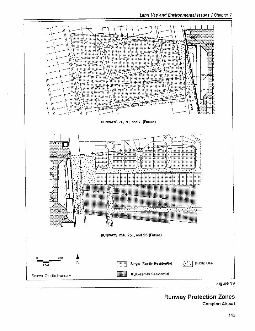
Land Use and Environmental Issues / Chapter 7
\RUNWAYS 7L, 7R, and 7 (Future)
RUNWAYS 25R, 25L, and 25 (Future)
Å
No 200--
Feet o Public Usei: : : : : : ~ Single -Family Residential
1::::::::::1 Multi-Family ResidentialSource: On-site Inventory
Figure 19
Runway Protection ZonesCompton Airport
143
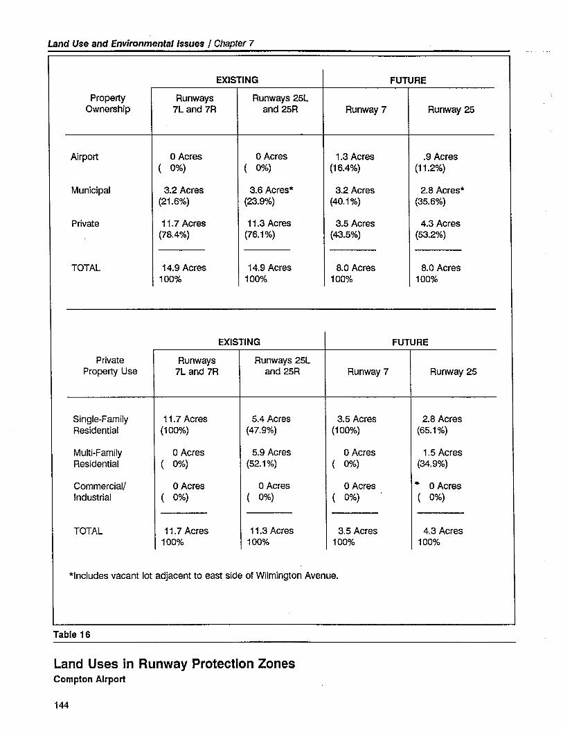
Land Use and Environmental Issues / Chapter 7
EXISTING FUTURE
Propert Runways Runways 25LOwnership 7L and 1R and 25R Runway 7 Runway 25
Airport o Acres o Acres 1.3 Acres .9 Acres( 0%) ( 0%) (16.4%) (11.2%)
Municipal 3.2 Acres 3.6 Acres. 3.2 Acres 2.8 Acres.(21.6%) (23.9%) (40.1 %) (35.6%)
Private 11.7 Acres 11.3 Acres 3.5 Acres 4.3 Acres(78.4%) (76.1 %) (43.5%) (53.2%)
TOTAL 14.9 Acres 14.9 Acres 8.0 Acres 8.0 Acres100% 100% 100% 100%
EXISTING FUTURE
Private Runways Runways 25LPropert Use 7L and 7R and 25R Runway 7 Runway 25
Single-Family 11.7 Acres 5.4 Acres 3.5 Acres 2.8 AcresResidential (100%) (47.9%) (100%) (65.1 %)
Multi-Family o Acres 5.9 Acres o Acres 1.5 AcresResidential ( 0%) (52.1 %) ( 0%) (34.9%)
Commercial! o Acres o Acres o Acres .. o AcresIndustrial ( 0%) ( 0%) ( 0%) ( 0%)
TOTAL 11.7 Acres 11.3 Acres 3.5 Acres 4.3 Acres100% 100% 100% 100%
.Includes vacant lot adjacent to east side of Wilmington Avenue.
Table 16
Land Uses in Runway Protection ZonesCompton Airport
144
Land Use and Environmental Issues / Chapter 7
acquisition and resale would be impractical and expensive because thereare no current or anticipated market forces to support such a change.Importntly as well, there is no obviously urgent need for action and theother measures proposed herein should be effective in preventing newapproach obstructions and incompatible uses. Given these present cir-cumstances, a major program to acquire and remove incompatible useswithin the Runway Protection Zones appears infeasible for the foresee-able future.
Nonetheless, despite the lack of current problems, the residential landuses within the Airport's Runway Protection Zones must be judged in-compatible with aviation activities. Ultimately, this land should be con-verted to compatible uses. The County and City should endeavor toreverse or mitigate this existing land use incompatibility at every reason-able opportunity. Although no specific actions to accomplish this objec-tive are presently recommended, the circumstances should be reevaluatedwhenever the Airport Master Plan, ALUC Plan, and General Plan areupdated.
Height Limitation
As noted earlier, numerous objects (e.g., buildings, antennas, pole lines,fences, walls, trees, and streets) penetrate the existing and future Part 77surfaces for Compton Airport. To maintain adequate clearances for land-ing aircraft, the runway thresholds have been displaced at each end.Unless there is effective regulation, construction of new structures couldrequire further displacement of the thresholds, effectively shortening therunway length available for landing aircraft. In addition, obstructionslocated near the departure end of the runway are a very real operationaland safety consideration for aircraft taking off. Accordingly, preventingfurther obstructions from being developed should be the highest priorityof both Los Angeles County and the City of Compton.
Approach Surfaces
If FAR Part 77 approach surfaces were used to strictly determine whereall structures are to be permitted, there would be two alternative meansof eliminating objects which penetrate the surfaces:
· Remove all structures which penetrate the approach surfaces associat-ed with the proposed new runway end locations. This would requirethe acquisition and demolition of numerous residences, removal ofseveral trees, and relocation of roads, utility poles, and perimeterwalls; or
· Relocate the physical runway ends - not merely the thresholds - so
that existing objects do not penetrate Part 77 surfaces. This would
145
Land Use and Environmental Issues / Chapter 7
require shortening the runway to a total useable length of just 2,440feet.
Neither of these alternatives is judged to be practicaL. As was discussedpreviously, the former would be expensive, and socially and politicallydisruptive. The latter would eliminate most of the utility of the Airportand could compromise operational safety.
Alternately, Part 77 surfaces could be applied only to new structures;existing structures would be permitted to remain. Since most of theparcels adjacent to the Airport are fully developed, this would restrictfurther development on a few parcels without significantly benefiting theAirport.
The most reasonable approach would be to not permit any structure oractivity to be developed in the area beneath the Part 77 approach zonesthat would result in further large congregations of people or penetrate therunway's existing threshold clearance plane.
For existing Runways 7L and 7R and future Runway 7, it is suggested thatno objects be permitted to penetrate a surface that begins at the dis-placed threshold, is 250-feet-wide at its inner point, 5,OOO-feet in length,
1,250-feet-wide at its outer point, with a slope of 26:1. Similarly, forexisting Runways 25L and 25R and future Runway 25, it is suggested thatthe same dimensioned surface be established, but with a slope of 38:1.It is further suggested that the pole lines, light poles, and trees located inthe public rights-of-way associated with Central and Wilmington Avenuesbe removed or relocated to mitigate their impact on airport operationsand safety.
Implementation and enforcement of this standard would ensure that theeffective length of the runway would not be further reduced or aircraftoperating safety compromised.
Trees constitute a significant number of the objects which penetrate thePart 77 approach surfaces. It is, therefore, essential that the growth of thetrees be surveyed on a regular basis and, when necessary, the treesshould be topped or, removed. Los Angeles County should work with
the City of Compton and adjacent propert owners to develop a mutuallyacceptable program for tree height control. The residents and land own-ers of the affected properties in the approaches should be contacted earlyin the process to request their participation and cooperation in any treeheight control program. Easements may be required in these areas topermit the required action.
Transitional Surfaces
The transitional surfaces defined by FAR Part 77 are intended to identifythe areas adjacent to the runway and approaches which should remain
146
Land Use and Environmental Issues / Chapter 7
free of objects. Numerous objects (e.g., light poles, structures, etc.) pene-trate the 7:1 transitional surfaces on both sides of the runway. It is feasi-ble that some of these penetrations can be mitigated by object removal orrelocation. A formal FAA airspace review of these penetrations will berequired to determine which penetrations are significant and the appro-priate mitigation response.
Overflight Areas
Very few complaints are received regarding aircraft operations at Comp-ton Airport. As long as this general acceptance by the surrounding com-munity continues, it is not recommended that an aggressive buyer aware-ness program be undertken. It could easily have the reverse of theintended effect. Los Angeles County should continue to monitor the
number and location of complaints. Airport staff should continue torespond to individual complaints in a timely manner. If a pattern ofcomplaints emerges, the staff should meet with the citizens concerned todetermine how their concerns can be addressed and, hopefully, resolved.
ENVIRONMENTAL IMPACTS OF AIRPORTDEVELOPMENT
As an integral element of this planning effort, an Initial Study of the envi-ronmental impacts associated with implementation of the Compton Air-port Master Plan was prepared. This Initial Study was conducted inaccordance with California Environmental Quality Act guidelines andrequirements. (tis included herein as Appendix E.
Both the temporary and permanent impacts of the proposed constructionand the long-term effects of the increased airport use are considered.The principal physical impacts will result from the modest earthwork andnew pavement associated with the relocation of the south parallel taxiwayand expansion of the building area facilities. Standard engineering designand construction methods are capable of adequately mitigating the poten-tial erosion, water quality, and other similar types of impacts. Givenprevious intensive development in the area, no impacts on endangeredspecies are anticipated, nor should there be any impact on potentialhistorical or archaeological artifacts.
Increased use of the Airport will produce some additional noise andsafety impacts, as addressed earlier in this chapter. The future singlerunway configuration will result in the concentration of all approach/departure flight paths along the existing Runway 7L-25R alignment.These impacts are not projected to have a significant effect on surround-ing land uses. Land use control actions recommended herein will serveto eliminate most potential future compatibility problems.
147
Land Use and Environmental Issues / Chapter 7
SUMMARY
Compton Airport is an importnt public air transportation resource servingthe citizens and businesses of the Compton area and the greater LosAngeles metropolitan region. If this vital general aviation airport is tosurvive and improve, it is essential that the City of Compton and LosAngeles County work closely together to prevent further incompatibledevelopment in the Airport's vicinity.
It is recommended that the height/hazard control actions and land usecompatibility measures identified herein be incorporated in all applicableplanning studies and zoning ordinances. The anticipated ALUC airportland use compatibility plan to be developed by Los Angeles Countyshould expand upon and definitively address the land use issues andmitigation recommendations identified in this Master Plan.
148
.~
Financialand
ImplementationIssues
8
Financial and ImplementationIssues
CAPIT At IMPROVEMENT PROGRAM
Cost Estimates
Table 1 in Chapter 2 sets forth cost estimates (based upon 1991 dollarvalues) for proposed airport development at Compton Airport over thenext 20 years. The estimates are tabulated in three stages (0-5 years, 5-10 years, and 10-20 years) consistent with the anticipated project imple-mentation sequence. It must be emphasized that the developmental costspresented in Table 1 have been estimated on an order-of-magnitude basisfor preliminary planning and programming purposes only. Specific projectanalysis and detailed engineering design will be required at the time of
project implementation to provide more refined and up-to-date estimatesof developmental costs. As presented in Table 1, the Master Plan pro-jects a total Capital Improvement Program cost of approximately $6.3million over the 20-year planning period.
Capital Funding Sources
There are a variety of sources from which funding and financing for pub-licly-owned airport facilities and improvements can be obtained. Thesesources include federal grants, state grants and loans, airport sponsor self-funding, and private investment.
Federal Grants
The most common source of federal aid for airport facilities is currentlythe Airport Improvement Program (AlP) administered by the Federal Avia-tion Administration. Re-established in 1987, the AlP is the latest evolu-tion of a program originally authorized by Congress in 1946 as the Feder-al Aid to Airport Program (FAAP).
149
Financial and Implementation Issues / Chapter 8
The AlP is based upon a trust fund concept, allocating aviation-generatedtax revenues for specified airport facilities on a local matching share basis.The program currently provides for 90% federal participation and 10%local participation on eligible airport projects in the state of California.Historically, the local match requirement has ranged as high as 50%.Whether the relatively generous 90% federal share wil continue beyondthe current legislation's expiration in 1992 is not certin.
Although the AlP is designed specifically for public airport improvement,there are other federal programs which can also be applied to airportneeds. The federally-funded Economic Development AdministrationProgram and the State and Local Fiscal Assistance Act of 1972, as amend-ed, have also been used on a limited basis to fund airport facilities nototherwise eligible for AlP grants. As it is relatively difficult for publicairport such as Compton Airport to qualify for these special federal fund-ing programs, these resources have not been considered in the formula-tion of Master Plan funding alternatives.
State Grants and Loans
The California Aid to Airport Program (CMP), administered by the StateDivision of Aeronautics, is similar to the federal AlP grant program inas-much as the state program provides airport development funds on amatching share basis, which is currently 90% state and 10% locaL. Thestate grants are allocated through the California Transporttion Commis-sion and are governed by the priorities set forth in the State Transport-tion Improvement Program (STIP).
Typically, the state grant program has concentrated on construction ofairfield improvements that primarily benefit general aviation users. How-ever, funding opportunities within this program are somewhat limited atpresent due to state funding constraints. An airport improvement projectsubmitted for a CMP grant faces substantial statewide competition forlimited funds.
The State Division of Aeronautics also administers an Annual Grant Pro-gram through which all public airport in the state receive $5,000 peryear to be used for grant eligible projects. Funds received must be keptin a Special Aviation Account and, with permission from the Division ofAeronautics, can be accumulated for up to five years toward a largecapital project. The funds can also be used as part of a local match for afederal grant.
One other funding source available from the California Division of Aero-nautics is the State Airport Loan Program. This program was establishedto allj)w public airport owners the opportunity to borrow funds at lowerthan commercial interest rates for use on specified revenue-generatingprojects and as the local share of FAA grant-funded projects. In the past,
150
Financial and Implementation Issues / Chapter 8
the most common use of these loans was for hangar construction. Morerecently, the primary use has been for the local share of an FAA grant.
Due to recent changes in the State's taxing authority, additional Statemonies may soon be available to supplement these State airport develop-ment funding programs.
Airport Sponsor Self-Funding
At large, publicly-owned airport, this source of funding typically involvesthe issuance of general obligation bonds or revenue bonds. Generalobligation bonds are backed by the full faith and credit of the issuinggovernment agency. General obligation bonds are usually limited by arestriction or cap placed on the issuing governmental agency's indebted-ness. Revenue bonds are secured by the pledge of revenue from one ormore airport facilities. A special disadvantage of revenue bonds is thecoverage requirement that net operating revenue exceed debt service bya stipulated ratio. Additionally, the fixed underwriting costs and complex-ities of a bond sale generally dictate their use for larger scale projectsonly. For Compton Airport, the costs and restrictions associated with theissuance of general obligation bonds or revenue bonds combine to makesuch sources impractical for use in funding airport capital projects.
At publicly-owned airport the size and character of Compton Airport,airport sponsor self-funding is principally provided by a combination ofairport-generated income and retained earnings and the airport sponsor'sinternal financial resources (i.e., Los Angeles County Aviation Divisiongeneral funds). Funding of airport improvements and providing the localshare for grants-in-aid from these sources is the simplest and most eco-nomical method because direct interest costs are eliminated.
In the specific case of Compton Airport, operating revenues are significantand operating expenses are modest. The Airport is fully capable of sup-porting its operational and maintenance costs and contributing a signifi-cant surplus for use in funding necessary airport capital improvements. Inaddition, the County may find it necessary and/or desirable to use CountyAviation Division general fund resources to provide supplemental fundingor interim financing for airport capital development. Potentially, as air-port activity increases, this form of sponsor funding can be supplanted bya funding program based entirely upon federal and state grants, airport-generated income, and private investment.
Private Investment
Private sector investment is an importnt source of funding for such air-port facilities as fixed base operations and aircraft storage hangars. LosAngeles County can continue to enhance the Airport's attractiveness toprivate investors by promoting the Airport, improving its facilities, andexpanding its service offerings. By maintaining a prudent lease policy and
151
Financial and Implementation Issues / Chapter 8
enforcing reasonable development standards, additional private invest-ment can be attracted to the Airport. In this manner, the County can shiftthe burden of financing certin facility development to the tenant whileincreasing the asset value of the Airport, thereby adding to the Airport's
attractiveness and revenue-producing capability.
The most common sources of funding for private sector development arecommercial lending institutions and insurance companies. In the case ofprivate development on public lands, these types of financing may bedifficult and expensive to obtain because the borrower can encumberonly the improvements as loan collateral, not the underlying publiclyowned land. These conditions necessitate close attention to leasingpolicies and tenant contract negotiations. It is essential that agreementsbe reached with the tenants which provide for adequate airport revenuesand facility development, while encouraging private investment and satis-fying the tenant's borrowing requirements. Specifically, the lease termmust be sufficient to allow reasonable investment amortization over theperiod of the agreement.
On occasion, private gifts and contributions are a source of funding forcertin airport improvements. Often, the private contribution facilitatesthe development of public airfield improvements that jointly benefit boththe private and public sectors.
Conclusions
As noted previously, the proposed Capital Improvement Program will total$6.3 million over the projected 20-year period, with $80,000 of this totalto be applied toward projects in the initial five-year period. Assumingthat full funding is available from AlP and/or CAAP grants and that privatefunds are invested as anticipated, the County's share over the 20-yearplanning period will be about $3.7 million. It is anticipated that theCounty's share will be funded through a combination of Compton Airportfunds (income and rctained earnings) and County Aviation Division funds.
PRO FORMA FINANCIAL PROJECTION
A ten-year projection of operating revenues, operating expenses, and netincome for Compton Airport is set forth in Table 17. These values areintended as an initial guide for financial planning purposes. It is recom-mended that the County periodically update and revise this financialprojection to correspond with future information.
The projection focuses on the first five years of the planning period. Alldata is presented in 1991 dollar values; no attempt is made to adjust for
152
Financial and Implementation Issues / Chapter 8
future inflation; The projection values set forth in Table 17 are basedupon the following factors and specific planning assumptions:
· Aviation activity at Compton Airport - both based and annual opera-tions - will increase as anticipated by the Master Plan forecasts (See
Chapter 4-Table 5).
· All revenue and expense categories will track the activity levels andfacility development scenarios identified in previous chapters.
· Airport management will continue to review and adjust all rates andcharges on an annual basis consistent with demand and airport role.As a minimum, the rates and charges should track the Consumer PriceIndex to maintain constant value.
· Eligible capital improvements will be financed to the maximum extentpossible with Federal Aviation Administration Airport ImprovementProgram funds and State of California grant/loan program funds, withthe County's share coming from airport income and retained earnings,and County Aviation Division funds.
· No major capital expenditures other than those identified in this reportwill be required during the forecast period.
· All T-hangar development will be constructed as demand warrants andwill be funded by the County. Corporate hangars and FBO facilitieswill be financed by the private sector. Comparative advantages anddisadvantages of other hangar financing options are discussed in Ap-
pendix F - Hangar Financing Options.
FINANCIAL SUMMARY
As can be seen in Table 17, Compton Airport's projected income andretained earnings should be adequate to fund the sponsor's share of theCapital Improvement Program costs associated with the short-range (i.e.,five-year) financial planning period. This is not surprising in that themajor portion ($6.2 million or approximately 98.7%) of the Airport's 20-year Capital Improvement Program local share requirement occurs be-yond the initial five-year period. It is anticipated that the cumulativeincome generated by the Airport will also be suffcient to fund the spon-sor's share of all capital improvements identified in the Master Plan.However, due to possible cash flow considerations, supplemental fundingand/or interim financing will be required to provide for the timely andcost-effective implementation of the Airport Capitallmprovement Pro-gram.
153
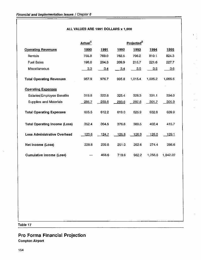
Financial and Implementation Issues / Chapter 8
ALL VALUES ARE 1991 DOLLARS x 1,000
Actuai1 Proiected2
OperatinQ Revenues 1990 1991 1992 1993 1994 1995
Rentals 755.8 769.0 782.5 796.2 810.1 824.3
Fuel Sales 198.8 204.3 209.9 215.7 221.6 227.7
Miscellaneous 3.3 3.4 -- -- -- 3.6
Total Operating Revenues 957.9 976.7 995.8 1,015.4 1,035.2 1,055.6
OperatinQ Expenses
Salaries/Employee Benefits 319.8 322.6 325.4 328.3 331.1 334.0
Supplies and Materials 285.7 289.6 293.6 297.6 301.7 305.9
Total Operating Expenses 605.5 612.2 619.0 625.9 632.8 639.9
Total Operating Income (Loss) 352.4 364.5 376.8 389.5 402.4 415.7
Less Administrative Overhead 123.6 124.7 125.8 126.9 128.0 129.1
Net Income (Loss) 228.8 239.8 251.0 262.6 274.4 286.6
Cumulative Income (Loss) 468.6 719.6 982.2 1,256.6 1,842.22
Table 17
Pro Forma Financial ProjectionCompton Airport
154
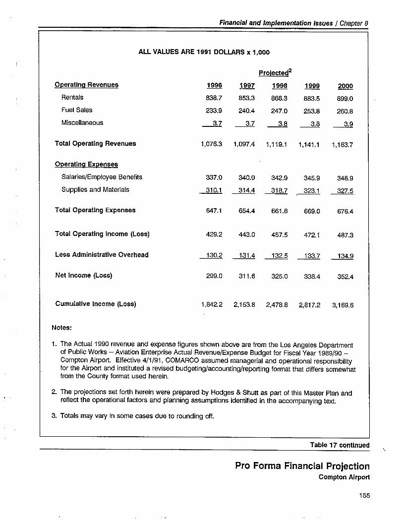
Financial and Implementation Issues / Chapter 8
ALL VALUES ARE 1991 DOLLARS x 1,000
Proiected2
Operatina Revenues 1996 1997 1998 1999 2000
Rentals 838.7 853.3 868.3 883.5 899.0
Fuel Sales 233.9 240.4 247.0 253.8 260.8
Miscellaneous ~ ~ ~ ~ ~Total Operating Revenues 1.076.3 1,097.4 1,119.1 1,141.1 1.163.7
Operatina Expenses
Salaries/Employee Benefits 337.0 340.0 342.9 345.9 348.9
Supplies and Materials 310.1 314.4 318.7 323.1 327.5
Total Operating Expenses 647.1 654.4 661.6 669.0 676.4
Total Operating Income (Loss) 429.2 443.0 457.5 472.1 487.3
Less Administrative Overhead 130.2 131.4 132.5 133.7 134.9
Net Income (Loss) 299.0 311.6 325.0 338.4 352.4
Cumulative Income (Loss) 1,842.2 2.153.8 2,478.8 2,817.2 3.169.6
Notes:
1. The Actual 1990 revenue and expense figures shown above are from the Los Angeles Departmentof Public Works - Aviation Enterprise Actual Revenue/Expense Budget for Fiscal Year 1989/90-Compton Airport. Effective 4/1/91, COMARCO assumed managerial and operational responsibiltyfor the Airport and instituted a revised budgeting/accounting/reporting format that differs somewhatfrom the County format used herein.
2. The projections set forth herein were prepared by Hodges & Shutt as part of this Master Plan andreflect the operational factors and planning assumptions identified in the accompanying text.
3. Totals may vary in some cases due to rounding off.
Table 17 continued
Pro Forma Financial ProjectionCompton Airport
155
Financial and Implementation Issues / Chapter 8
As noted above, over the course of the 20-year planning period, it isanticipated that Compton Airport operating income wil be adequate tosupport the proposed Capital Improvement Program. The Airport's fiscalcondition could be improved by further reducing expenses or increasingrevenues. Operating expenses are already relatively modest, however,and a significant reduction in expenses may not be achievable. Airportrevenues could be enhanced by developing new sources of airport-relat-ed revenue or by increasing rates charged to airport lessees, permittees,and users. Caution must be exercised, however, in establishing higherrates at the Airport. A reasonable balance must be sought between theneed for a financially viable airport, the continuation of subsidies to theprivate sector, and general aviation market conditions. In this regard,Compton Airport's rates and fees structure should be established in amanner which permits the County to safely operate and improve the Air-port while attracting the Airport's target user groups - personal/recre-ational aircraft users and small corporate/business aircraft users desiringgeneral aviation air transporttion access to the central Los Angeles area.
MASTER PLAN ADOPTION AND IMPLEMENTATIONACTIONS
In order for the County to proceed with adoption of the Airport MasterPlan and implementation of the first-phase improvement projects, a vari-ety of state and federal environmental and other review or permit actionsmust be completed. The major steps in this process are as follows:
Master Plan Adoption
· Environmental Impact Documentation - As part of this Master Plan,an Initial Study assessing the potential environmental impacts associat-ed with the construction and long-term use of the proposed airportimprovements has been prepared in accordance with California Envi-ronmental Quality Act (CEQA) guidelines (see Appendix E). It is antic-ipated that this Initial Study will be sufficient to enable preparation ofa Negative Declaration allowing adoption of the Master Plan. Moresubstantial environmental documentation may be necessary in accor-dance with state guidelines (CEQA) before the major projects pro-posed in the plan can be implemented (see below). No Federal Avia-tion Administration environmental review is required for adoption ofthe Master Plan.
· County Aviation Commission - The Aviation Commission has partici-pated in the preparation of the Airport Master Plan through discussions
held at regular Commission meetings. The Commission should review
156
Financial and Implementation Issues / Chapter 8
the completed draft Master Plan Report and pass its recommendationsalong to the County Board of Supervisors.
· Airport Land Use Commission - State law requires that an airportmaster plan be referred to the appropriate county airport land usecommission (ALUq to determine if the master plan is consistent withthe commission's plan. The Los Angeles Regional Planning Commis-
sion is currently the designated ALUC in Los Angeles County. Recentchanges is state aeronautics law as it pertins to the ALUC in LosAngeles County, together with the lack of locally adopted airport landuse plans, lend uncertainty to this review process. Nevertheless, it issuggested that the Regional Planning Commission be given the oppor-tunity to review and comment upon the Compton Airport Master Plan.
· County Planning Commission - Action by the County PlanningCommission may be required for two purposes: (1) to determine theconsistency between the Airport Master Plan and the County GeneralPlan; and (2) to certify a Negative Declaration.
· Board of Supervisors - The County Board of Supervisors has theultimate responsibility for adoption of the Airport Master Plan. TheBoard's action should follow established County procedures regardingpublic hearings, public notification, etc.
· Federal Aviation Administration - On-going coordination has been
maintained with the FAA throughout the Master Plan study and the
agency will receive the draft plan for informal review. Following theCounty's adoption of the Master Plan, the FAA will conduct a formalinternal coordination and review of the Airport Layout Plan drawings.After any necessary technical revisions are made, the FAA wil thenapprove the Airport Layout Plan as the basis for the engineering designand grant eligibility of specific projects. The FAA's approval of theplan is not a commitment to the future funding of any given project.
Implementation
· Proposed Projects - As described elsewhere in this report, several ofthe proposed airport improvements are programmed for early imple-mentation. These projects include the establishment of appropriatelyconfigured Object Free Areas and Runway Safety Areas for each run-way end; completion of the new terminal building and support facili-ties; and installation of additional aircraft storage hangars. The bulk ofthe capital-intensive airport improvements (e.g., upgrading Runway 7L-25R, new fueling facility, and airport traffic control tower) are pro-grammed to occur during the mid-range (5-10 year period).
· Project Funding - The County should assess the availability andtiming of local funds that can be committed to the proposed airportimprovements. Once a decision is made to proceed with specific
157
Financial and Implementation Issues / Chapter 8
projects, an Airport Improvement Program grant preapplication shouldbe submitted to the California Division of Aeronautics with a copy tothe Federal Aviation Administration as soon as possible.
· Engineering Deign - The Airport Master Plan Report and AirportLayout Plan drawings serve only as the starting point for the moredetailed engineering design work necessary for actual construction ofthe proposed improvements. After the Master Plan has been adoptedand a decision has been made to construct the proposed projects, theCounty should proceed in a timely manner to arrange a contractualagreement with a qualified airport engineer. To assure a continuity indesign development, it is suggested that the agreement cover not justthe immediate projects, but other major improvements proposed to beconstructed over the next three to five years.
· Environmental Impact Doumentation - To satisfy CEQA require-ments, an environmental analysis may need to be performed withregard to the proposed runway reconstruction and increase in aircraftparking capacity. There is no apparent requirement for preparation ofa federal environmental document. The projects proposed in theMaster Plan do not meet the Federal Aviation Administration criteriaindicating the need for an Environmental Assessment and they aretherefore regarded as Categorically Excluded from federal environmen-tal review.
· State Airport Permit - The proposed modifications to the runway
configuration may require that the Airport Permit issued by the Califor-nia Division of Aeronautics be amended. The need for this actionshould be reviewed with the State.
· Airspace Review - Before work is conducted on or near the airportrunway, a "Notice of Proposed Construction" must be submitted to the
Federal Aviation Administration for their review and comment.
158
~Aviation
MarketingProgram
\,--
9
Aviation Marketing Program
INTRODUCTION
Over the past decade, the nation's general aviation industry has been in atailspin. The industry has experienced significant decreases in aircraftproduction and sales, new pilot start, active pilot certificates, and aircraftusage. Only within the past year have general aviation activity indicesreflected a modest turnaround - a nationwide resurgence of interest inthe advantages and efficiencies of the general aviation air transporttionsystem.
In an affirmative response to these challenging market conditions, theCounty of Los Angeles directed the airport master plan consultant,Hodges & Shutt, to develop a program for marketing the facilities, capa-bilities, and services of Compton Airport to both the general aviationcommunity and the community-at-Iarge. The resultant program has beendeveloped with the goal of improving the Airport's overall operatingenvironment and financial position, encouraging the development andgrowth of desired on-airport aviation businesses and concessions, andenhancing user and public perception and understanding of the Airportand general aviation.
DISCUSSION
The aviation marketing program for Compton Airport is presented in foursections. The first section describes the Airport's present operational roleand user group characteristics. The second section draws upon the find-ings and conclusions of the Master Plan to project the Airport's futureoperational role and user group characteristics. In the third section, theopportunities, limitations, and potential iesponses associated with themarketing of the Airport are identified and explored. The fourth section,entitled Aviation Marketing Plan, presents a detailed listing of specificaviation marketing actions recommended for implementation at ComptonAirport.
159
Aviation Marketing Program / Chapter 9
This program has been prepared in a manner which encourages regularreview and updating by the County. As the general aviation marketenvironment evolves, it is recommended that this program be reviewedand adjusted to reflect changes in aviation market conditions, user needs,and airport service requirements.
PRESENT AIRPORT OPERATIONAL ROLE ANDAIRPORT USER GROUP CHARACTERISTICS
Since its establishment in 1924, Compton Airport's principal operationalrole has been as a base location for personal, recreational, and business
aircraft users living and working in the central Los Angeles area. In addi-tion, the Airport has served as an importnt area air access point fortransient aircraft users - particularly those users desiring a less complexand less expensive operating environment.
Of particular note is the relatively high percentage (approximately 35%) ofaircraft based at Compton Airport that are considered "enthusiast' aircraft.The enthusiast aircraft classification includes antique, classic, sport, ama-teur-built, and warbird aircraft types.
Supplementing the above noted fixed-wing aircraft activity is the relativelyrecent increase in helicopter activity occurring at the Airport. Withinrecent years, the Airport has experienced increased helicopter operationsby both private and public operators. Contributing substantially to thisincreased activity are the three helicopters based at the Airport and oper-ated by the City of Compton Police Department - Air Support Division.
The large majority of aircraft based at the Airport are single-engine piston-powered airplanes. Of the 350 aircraft based at Compton Airport in1990, 94% are single-engine airplanes, 5% are twin-engine airplanes, and1 % are helicopters. This mix of based aircraft has remained essentiallythe same over the past several years.
The predominant use of Compton Airport by both based and transientpersonal, recreational, and business aircraft users operating single-engineairplanes is largely the result of the following factors:
· Limited facilities and services are available at Compton Airport toattract and accommodate business and corporate users operating so-phisticated, high-performance, piston- and turbine-powered, multi-engine aircraft. Aeronautical facilities and services generally desiredby business and corporate aircraft users but not available at ComptonAirport include a precision instrument approach, runway length of5,000 feet or greater, a variety of ground transporttion options, andcorporate aircraft oriented fixed base operators.
160
Aviation Marketing Program / Chapter 9
· Availability of nearby well-equipped public-use airport (e.g., LosAngeles International, Long Beach, Torrance Municipal, and Haw-thorne Municipal) that offer the sophisticated airport facilities andservices desired by business and corporate aircraft operators. Theseairport are well positioned to serve the same market area as ComptonAirport.
· Availability of hangars suitable for storage of personal, recreational,
and business aircraft types.
':
· Compton Airport offers lower aircraft operating and storage costs thannearby airport.
· High area demand for airport facilities and services suitable for person-al and recreational aircraft use. There is no airport comparable toCompton located in the central Los Angeles area.
· The absence of an air traffic control tower at Compton Airport is seenby some small aircraft users as an attribute. On the other hand, mostoperators of sophisticated, high-performance aircraft view the absenceof an air traffic control tower as detrimentaL.
· The general perception by aircraft users that Compton Airport is not assecure as other area airport. This security interest is of particularconcern to corporate aircraft operators.
Over the past five years, Compton Airport based aircraft activity has fluc-tuated substantially - from a count of 365 aircraft in 1985, to a high of467 aircraft in 1988, to a current count of 350 in 1990. Annual opera-tions counts are estimated to have remained in the 90,000 range. Duringthis period, there has been no appreciable change in the Airport's opera-tional role. The Airport continues to serve primarily as a base location for
central Los Angeles area personal, recreational, and business aircraftusers. If any trend has been apparent, it has been a slight shift towardsgreater use of Compton Airport - both based and transient activity - bysophisticated, high performance, single-engine aircraft (e.g., BeechcraftBonanza, Cessna P-210, Piper Malibu, etc.) and public-service helicopters(e.g., City of Compton Police Department). This increased use of Comp-ton Airport by sophisticated business and corporate aircraft may be in partattributable to the recent development of the nearby Highway 91 industri-al corridor.
Nearby competitive public-use airport located within 10 nautical miles ofCompton Airport include Los Angeles International Airport (LA, LongBeach Airport (LGB), Torrance Municipal Airport (TOA), and HawthorneMunicipal Airport (HHR). The respective locations of these airport aredepicted in Chapter 3-Figure 7. All of these facilities are well-equippèdpublic-use airport capable of serving a wide range of sophisticated gener-
al aviation piston and turbine powered aircraft. Typically, only the more
161
Aviation Marketing Program / Chapter 9
sophisticated corporate aircraft make use of Los Angeles InternationalAirport.
FUTURE AIRPORT OPERATIONAL ROLE ANDAIRPORT USER GROUP CHARACTERISTICS
As indicated in Chapter 4, the Master Plan does not envision any substan-
tial change in the future operational role of the Airport or in the Airport'sfuture user group characteristics. Accordingly, it is anticipated that Comp-ton Airport's future operational role will be substantially the same as itspresent operational role - a base location for central Los Angeles area
personal, recreational, and business aircraft users. It can be anticipatedthat the Airport will see increased utilization by business and small corpo-rate aircraft. Aircraft types typical of this use category include high-perfor-mance single-engine airplanes (e.g., Beechcraft Bonanza, Cessna P210,Piper Malibu, etc.), light to medium twin-engine piston and turboprop-powered airplanes (e.g., Cessna 414, Beechcraft Baron, Piper Aerostar,Beechcraft King Air, etc.), and occasional light corporate jets (e.g., CessnaCitation, Beech 400, Lear 31, etc.). Such business and small corporateaircraft users, while they could better be accommodated at nearby LongBeach, Torrance Municipal, and Hawthorne Municipal airport, might be
attracted to Compton Airport because of its more convenient location andlower use costs.
In addition, it can be anticipated that the airspace in the vicinity ofCompton Airport will become increasingly complex and aircraft operatingrequirements more restrictive. Accordingly, marginal general aviationaircraft users may seek alternative, less complex airport in outlying areas.Aircraft remaining at Compton Airport will be relatively well-equippedand more regularly utilized.
Supplementing this fixed-wing aeronautical activity at Compton Airportwill be an increase in helicopter activity, particularly flight operationsgenerated by the City of Compton Police Department helicopter unit,Compton Airport fixed base operators, and business/corporate helicopteroperators. Additional helicopter activity will be generated by local munic-ipalities who choose to base their public-service (i.e., police, fire, emer-gency response, and community support) helicopters at the Airport.
The principal Airport user groups identified above - personal, recreation-al, and business aircraft users and public-service helicopter operators -can be allocated into "based" and "transient' use categories dependingupon the nature of the users' activity. Airport activity records indicatethat the predominant ,users of Compton Airport are its based clientele.Transient aircraft operations represent a relatively small portion of Comp-ton's activity. A significant percentage of Compton's transient operationsare believed to be generated by flght training aircraft which are based at
162
Aviation Marketing Program / Chapter 9
nearby airport such as Long Beach, Torrance Municipal, and HawthorneMunicipaL. Such aircraft prefer to use Compton Airport due to its lesscomplex operating procedures, lower traffc activity levels, and morehomogeneous air traffic mix.
AVIATION MARKETING OPPORTUNITY ANALYSIS
As part of this aviation marketing program, an analysis of aviation market-ing opportunities at Compton Airport was prepared. This analysis indi-cates that there are opportunities, limitations, and appropriate responsesassociated with the use of the Airport by each principal airport usergroup. These factors are identified in Table 18.
This analysis suggests that considerable capital and operating expenditureswould be required at Compton Airport to attract and accommodate high-performance multi-engine business and corporate airplanes on a regularbasis. These expenditures would include the substantial reconfigurationof the airfield (lengthened and strengthened runway, increased dimen-sional setbacks, and expanded aircraft parking areas) and the installationof an instrument approach. Considerable airport basing capacity wouldhave to be sacrificed to accommodate such operations. This findingfurther support the conclusion that the primary market groups for Comp-ton Airport are the personal, recreational, and business aircraft user.
AVIATION MARKETING PLAN
As stated at the outset, the goals of this aviation marketing program are:
(1 ) To improve the Airport's overall operating environment and financialposition; (2) to encourage the development and growth of desired on-airport aviation businesses and concessions; and (3) to enhance user andpublic perception and understanding of the Airport and general aviation.To fully realize these goals, it wil be necessary to accomplish the follow-ing marketing tasks:
· Endeavor to satisfy the Airport's existing based and transient aircraftuser groups.
· Attract additional based and transient aircraft users consistent with theAirport's stated operational role as a facility predominantly serving thepersonal, recreational, and business aircraft user groups.
· Provide for increased use of the Airport by public-service helicopteroperators.
163
Aviation Marketing Program / Chapter 9
· Provide a positive airport environment that encourages the develop-ment and growth of desired on-airport aviation businesses and conces-sions.
· Promote the attributes and advantages of the Airport to the respectiveaircraft user groups, local businesses, and the community-at-Iarge.
A comprehensive listing of aviation marketing actions has been preparedspecifically for use at Compton Airport. The listing is presented in foursections to differentiate between marketing actions related to based air-craft users, transient aircraft users, airport tenants and concessionaires,and the community-at-Iarge. .
Aviation Marketing Actions - Compton Airport Based AircraftUsers
The following actions should be considered in marketing Compton Air-port to its based aircraft users:
· Emphasize and promote desire to be "best general aviation airport inregion" and "general aviation gateway to the central Los Angeles area".
Cater to personal, recreational, and business aircraft users operatingsingle-engine and light tvVin-engine aircraft.
· Provide adequate physical plant (runways, taxiways, aprons, etc.) asidentified in the Airport Master Plan.
· Adequately maintain appearance and serviceability of all airport facili-ties and structures.
· Provide adequate approach instrumentation and lighting consistentwith airport operational role and user requirements.
· Establish a fee schedule which reflects the operational role of theAirport and the Airport's somewhat limited facilities, amenities, andcapabi I ities.
· Do not "over-design" or "over-build" facilities unnecessarily increasingcapital and operating costs.
· Offer an "open-doorJl management policy and effectively communicatewith airport users.
· Have a "suggestion box" and respond to suggestions through an airportnewsletter.
164
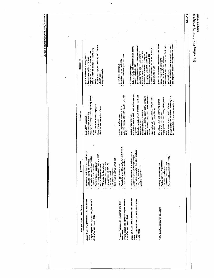
Avi
atio
n M
arke
tIng
Pro
gram
I C
hapt
er 9
;
Prin
cipa
l Air
port
Uae
r G
roup
Res
pons
esO
ppor
tunl
tlea
Um
ltatlo
ns
Bas
ed P
erso
nal,
Rec
reat
iona
l, an
d B
usin
ess
Use
r.(S
lng/
e-an
glne
and
ligh
t tw
ln,e
ngln
e al
rcra
lllt/x
ed-w
lng
and
rota
ry-w
ing)
Tra
nsie
nt P
erso
nal,
Rec
reat
iona
l, an
d B
us/.
nen
Use
r.(S
lngl
e,en
glne
and
ligh
t tw
in-e
ngin
e al
rcra
lllIlx
ed-w
lng
and
rota
ry,w
lng)
Bas
ed a
nd T
rans
ient
Bus
ines
s an
d C
orpo
rate
Use
r.(C
ompl
ex a
nd tu
rbIn
e al
rcra
ll/fx
ed-w
lng
and
rota
ry-w
Ing)
Pub
llc.S
ervl
ce H
elic
opte
r O
pera
tors
Pre
dom
inan
t exi
stin
g ai
rpor
t ser
vice
rol
eA
dequ
ate
exis
ting
Infr
astr
uctu
reN
o ne
arby
com
para
ble
com
petit
ion
Out
side
of T
CA
and
AR
SA
Pro
xim
ity to
use
r po
pula
tion
Less
cos
tly th
an L
GB
, TO
A, a
nd H
HA
Sm
all T
-ha
ngar
s av
aila
ble
FB
O's
cat
er to
ligh
t aIr
craf
tLo
wer
cos
t 1ue
l and
sto
rage
Hom
ogen
eous
air
traf
fic m
ixLo
w n
oise
Impa
ctL
ess
traf
fc c
onge
stio
nC
onsi
dera
ble
Uen
thus
last
. airc
raft
Abo
ve O
ppor
tuni
ties
plus
:P
ossi
ble
to a
void
TC
A a
nd A
RS
A p
enet
ratio
nC
offe
e eh
op/s
nack
bar
ava
ilabl
e
Pro
xim
ity to
cen
tral
LA
are
a bu
sine
sses
Low
er c
ost 1
uel a
nd s
tora
ge c
harg
esLe
sa tr
affic
con
gest
ion
than
at a
ltern
ativ
es -
LGB
, TO
A, a
nd H
HA
Exc
elle
nt fr
eew
ay a
cces
s
exis
ting
airp
ort s
ervi
ce r
ole
Pos
itive
com
mun
it pe
rcep
tion
Les
s co
mpl
ex a
irsp
ace
Low
er c
ost f
uel a
nd s
tora
geP
rese
nce
enha
nces
airp
ort s
ecur
ity
Laok
of I
FA
app
roac
hLi
mite
d ha
ngar
ava
ilabi
lity
Com
plex
are
a ai
rspa
ce a
nd o
pera
ting
proc
e-du
res
Alrc
reft
mus
t be
Mod
e C
equ
ippe
dS
ecur
ity c
once
rns
Neg
ativ
e us
er p
erce
ptio
n of
are
a
Abo
ve L
imita
tions
plu
s:Li
mite
d gr
ound
tran
spor
t opt
ions
Attr
activ
e ne
arby
alte
rnat
ives
(LO
B, T
OA
, and
HH
A)
Abo
ve L
imita
tions
plu
s:In
adeq
uate
run
way
leng
th a
nd w
eigh
t-be
arin
gca
paci
tLa
ck o
f cor
pora
te a
ircra
ft or
ient
ed F
aD's
and
serv
ice
amen
ities
Pot
entia
l for
noi
se p
robl
ems
Nee
d to
sig
nific
antly
adj
ust f
acili
ty c
onfig
ura-
tion
to a
ccom
mod
ate
larg
er/ f
aste
r co
rpor
ate
airc
raft
Com
petin
g w
ith n
earb
y LG
B, T
OA
, and
HH
RLa
ck o
f air
traf
fc c
ontr
ol to
wer
Mix
of f
ixed
-wIn
g an
d ro
tary
-win
g ai
rcra
ftN
o ai
r tr
affic
con
trol
tow
erC
onst
rain
ed h
elic
opte
r fa
cilty
dev
elop
men
tar
eaC
onst
rain
ed a
irfie
ld o
pera
tiona
l are
aPo
tent
Ial f
or n
oIse
pro
blem
s -
espe
cial
ly d
ur-
Ing
late
nlg
htJe
arly
mor
ning
ope
ratio
ns
Pur
sue
Inst
alla
tion
of IF
A a
ppro
ach
Incr
ease
ava
ilabi
lit o
f ha
ngar
sIm
prov
e ai
rpor
t and
enh
ance
ser
vice
sO
fer
Dse
lf-s
ervl
ce f
uelin
g- to
low
er f
uelin
gco
sts
Cat
er to
per
sol)a
l, re
crea
tiona
l, an
d bu
sine
ssai
rcra
ft u
sers
Upgrade securit
Abo
ve R
espo
nses
plu
s:Pr
ovid
e re
ntal
car
ava
ilabi
litM
arke
t Com
pton
Air
port
attr
ibut
es
Abo
ve R
espo
nses
plu
s:E
xend
run
way
and
Incr
ease
wei
ght-
bear
ing
capa
cit o
f alrt
leld
($$
)E
ncou
rage
dev
elop
men
t 01
corp
orat
e ai
rcra
ftor
ient
ed F
BO
's a
nd s
ervi
ce a
men
ities
Bui
ld c
orpo
rate
airc
raft-
size
d ha
ngar
sD
evel
op n
oise
aba
tem
ent p
rogr
amR
econ
flgur
e ai
rfie
ld to
acc
omm
odat
ela
rger
J1as
ter
corp
orat
e ai
rcra
ft (
$$)
Cat
er to
bus
ines
s/co
rpor
ate
airc
raft
use
rs.
Est
ablis
h A
TC
tow
er
esta
blis
h pr
oced
ures
to c
oord
inat
e fix
ed-
and
rota
ry-w
ing
airc
raft
oper
atio
nsE
stab
lish
air
traf
fic c
ontr
ol to
wer
Prov
ide
for
a de
dloa
ted
helic
opte
r fa
oliit
de-
velo
pmen
t are
aE
stab
lish
defln
ed n
oise
aba
tem
ent a
ppro
ach'
and
depa
rtur
e pa
ths
for
helic
opte
r op
erat
ions
Tab
le 1
8
Mar
ketin
g O
ppor
tuni
ty A
naly
sis
Cam
pIon
Airp
ort
Aviation Marketing Program / Chapter 9
· Establish rules/regulations, insurance requirements, and operatingprocedures in a manner which reasonably encourages as well as con-trols on-airport aviation activity.
· Encourage infrequent/inactive aircraft to relocate to less active areas ofthe Airport to facilitate active users' interests.
· Offer a range of tied own and hangar storage options for various levelsof users (from "less expensive inactive exterior storage" to "deluxeenclosed storage").
· Do not unduly restrict use of T-hangars for non-aviation storage (i.e.,RV storage), provided principal use is for aircraft storage and reason-able safety/fire standards are met.
· Permit multiple aircraft storage in single-unit T-hangar at reasonablecost.
· Encourage development of small commercial-use rental hangars forexperimental/antique aircraft shops, private aircraft restoration or mod-ification, specialty services, etc.
· UNICOM should be regularly monitored and utilized to provide usefulairport information.
· Emphasize Compton Airport's less complex procedures and lower usecosts as compared with nearby Long Beach, Torrance Municipal, andHawthorne Municipal airport.
· Offer general aviation and enthusiast groups facilities to gather andmeet. Encourage the groups' positive interaction with the public andthe Airport. Among the groups to be considered are:
- Aircraft Owners and Pilots Association- Experimental Aircraft Association
- Antique Airplane Association
- 99's
- Air Explorers
- Civil Air Patrol
- Flying clubs
- Local pilot organizations
· Permit individual based aircraft owners to perform preventative main-tenance on their own aircraft consistent with the applicable FederalAviation Regulations (FAR's 43 and 91).
· Provide an aircraft wash rack and maintenance shed for based aircraftowners' use.
165
Aviation Marketing Program / Chapter 9
· Encourage quality, stable, competitive FBO's with adequate servicesand facilities.
· Offer reasonably priced fuel with attentive line service. Emphasizequick, efficient service and increased hours of fueling availability. Fuelcosts should reflect role of the Airport and the level of facilities/servic-es.
· Offer 80 octane AVGAS or ASTM D439 auto fuel (i.e., "MOGAS").This offering should prove especially attractive to the users of "enthusi-ast' type aircraft.
· Consider economic advantages and disadvantages of fixed (e.g., fuelisland) versus mobile (e.g., refueler trucks) refueling systems.
· Consider user "self-service" fueling program to reduce costs and en-hance hours of availability. Investigate possibility of implementing a24-hour access, credit-card activated, self-service fueling system.
· Provide reasonable automobile access to aircraft parking/tiedown/hangar areas to facilitate authorized user access to aircraft.
· Provide reasonable levels of security without unduly restricting legiti-mate users and visual access for public.
· Market the Airport as a base of operations for helicopters - bothbased and transient.
· Provide a well-equipped state-of-the-art flight planning center (forbased and transient users) with direct FSS line, weather computer,motels/restaurants listing, Weather Channel TV, etc.
.:\
· Approach compatible tenants at competitive airport and attract themto Compton Airport. Obtain names/addresses of competitive airport'based and transient users. Send direct marketing mailing to all suchprospective tenants and users.
· Send marketing letters to "enthusiast' aircraft owner groups (use enthu-siast magazine and club mailing lists).
Aviation Marketing Actions - Compton Airport TransientAircraft Users
The following actions should be considered in marketing Compton Air-port to its transient aircraft users:
· Emphasize and promote desire to be "best general aviation airport inregion" and "general aviation gateway to the central Los Angeles area".
166
Aviation Marketing Program / Chapter 9
Cater to personal, recreational, and business aircraft users. Promoteadvantages of using Compton Airport as a destination or fuel/rest stop.
· Approach compatible transient aircraft operators at nearby competitiveairport (Long Beach, Torrance Municipal, and Hawthorne Municipalairport) and attract them to Compton Airport. Use direct mailingtechniques to identify and attract compatible aircraft operators.
· Conduct a "fuel island survey" of transient aircraft users' service andfacility requirements and desires. Determine what makes the airportattractive to transient aircraft users and promote that via advertise-ments, flyers, etc.
· Tailor line services to attract transient users. Provide low-cost fuel,both 80 and 100 octane; quick, efficient service; and adequate hoursof availability. Offer a transient fuel discount coupon to attract newtransient customers.
· Offer 24-hour airport access and aeronautical service (particularlyaviation fuel service).
· Market the Airport to local service providers (rental car companies,motels, restaurants, resort, recreational activities, etc.). Promote avail-ability of such services to transient user group.
· Provide adequate on-airport signage (i.e., commercial tenants listing,transient parking, fueling, frequencies, vehicle loading areas, etc.) andlighting (i.e., transient parking area and public areas).
· Provide easily recognizable marked transient parking positions withquality tiedowns (preferably taxi-thru positions).
· Encourage development of public ground transporttion options (lightrail/limo/taxi/bus services) from the Airport throughout the communityand into central Los Angeles. Promote availability of such services totransient user group.
· Encourage free courtesy van service to/from area hotels, motels, res-taurants, attractions, etc.
· Ensure that all airport information guides accurately detail the Airport'sfacilities, services, and attractions.
· Provide pilots and airport users with printed airport data sheets suit-able for insertion in Flight Guide, Pilots Guide to California Airport,leppeson Airway Manuals, etc.. These data sheets should identify theAirport's facilities, services, commercial tenants, and attractions.
· Emphasize newly developed airport terminal/snack bar/coffee shop toattract the flying public and local citizens to the Airport.
167
Aviation Marketing Program / Chapter 9
Aviation Marketing Actions - Compton Airport Tenants andConcessionaires
The following actions should be considered in marketing Compton Air-port to its based commercial tenants and concessionaires:
· Stimulate the economic health of on-airport FBO's and concession-
aires. Encourage them to provide quality, reasonably priced servicesand facilities consistent with customer demand and airport role.
· Support airport tenants and concessionaires with adequate on-airportdirectional signing and commercial services listings.
· Participate in a joint marketing program with commercial tenants.Airport and tenants could share in the cost of advertising and promo-tion. Consider local and regional exposure.
· Be flexible and innovative in promoting and establishing new aviation
activities and businesses. Consider the following activities:
- Foreign air carrier or college-affiliated aviation training programs- FAA-approved airframe and powerplant technician training pro-
grams- Specialized aircraft repairs, modifications, interiors, etc.- Experimental aircraft supply, equipment, manufacturing, etc.
- Aircraft rebuilding and refurbishment
- Aircraft power plant maintenance, overhaul, and accessory repair
· Encourage the establishment of general aviation-related "incubatorindustries" and aviation specialty shops consistent with reasonablesafety requirements and public policy considerations.
· Encourage active use of aircraft as opposed to inactive aircraft storage.Consider designating an inactive aircraft storage area on the Airport(lower cost, lower public visibility, unimproved area). Active aircraftare more likely to patronize on-airport commercial tenants and con-cessionaires.
· Establish rules/regulations, fees, insurance requirements, and operatingprocedures in a manner which reasonably encourages as well as con-trols on-airport aviation activity.
· Do not "over-design" or "over-build" airport facilities unnecessarilyincreasing costs that must be passed on to airport tenants and users.
168
Aviation Marketing Program / Chapter 9
Aviation Marketing Actions - Compton Airport AreaCommunity-at-Large
The following actions should be considered in marketing Compton Air-port to its surrounding community:
· Encourage the general public and local community to get positivelyinvolved in "their" airport and in general aviation. Suggestedapproaches include:
- Air shows/air fairs/community airport days/FBO open houses, etc.
- "Learn to fly" promotions through FBO's.
- Airport participation in General Aviation Market Expansion (GAME)Plan, as sponsored by The General Aviation Task Force.
- Get local media interested in positive aspects of the Airport andaviation.
- Establish regular "aviation column" in local media.
- Issue regular media releases regarding airportaviation developmentand activities.
- Develop and distribute airport informational brochure thatemphasizes airport services and capabilities and benefits to localcommunity.
- Have airport representatives (manager, FBO's, etc.) regularly speakto community service groups and civic organizations.
- Encourage airport tours by school and civic groups.
- Have the Airport participate/contribute to community's non-aviationevents (i.e., July 4th parade, etc.).
· Provide adequate airport-related directional signing off-airport.
· Offer attractive public viewing and picnic areas overlooking airfieldand airport activity areas.
· Establish connection with local colleges and vocational training schoolsto foster joint educational programs. Provide airport "internships" forselected students.
· Ensure that local community economic development-groups (e.g.,Chamber of Commerce, realtors, tourism agencies, etc.) know aboutthe Airport and actively promote it in their marketing effort.
169
Aviation Marketing Program / Chapter 9
· Offer an "open-door" airport management policy and effectively com-municate with general public and local community regarding suchissues as aircraft noise, safety, and airport development.
· Market Airport's capabilities and services to local businesses and cor-porations. Encourage local businesses to use airport tenant servicessuch as air charter, aircraft rental and flght instruction, and aerialphotography.
170

1 ~
ArPrp)(~~d~(Ç~~
.~
,
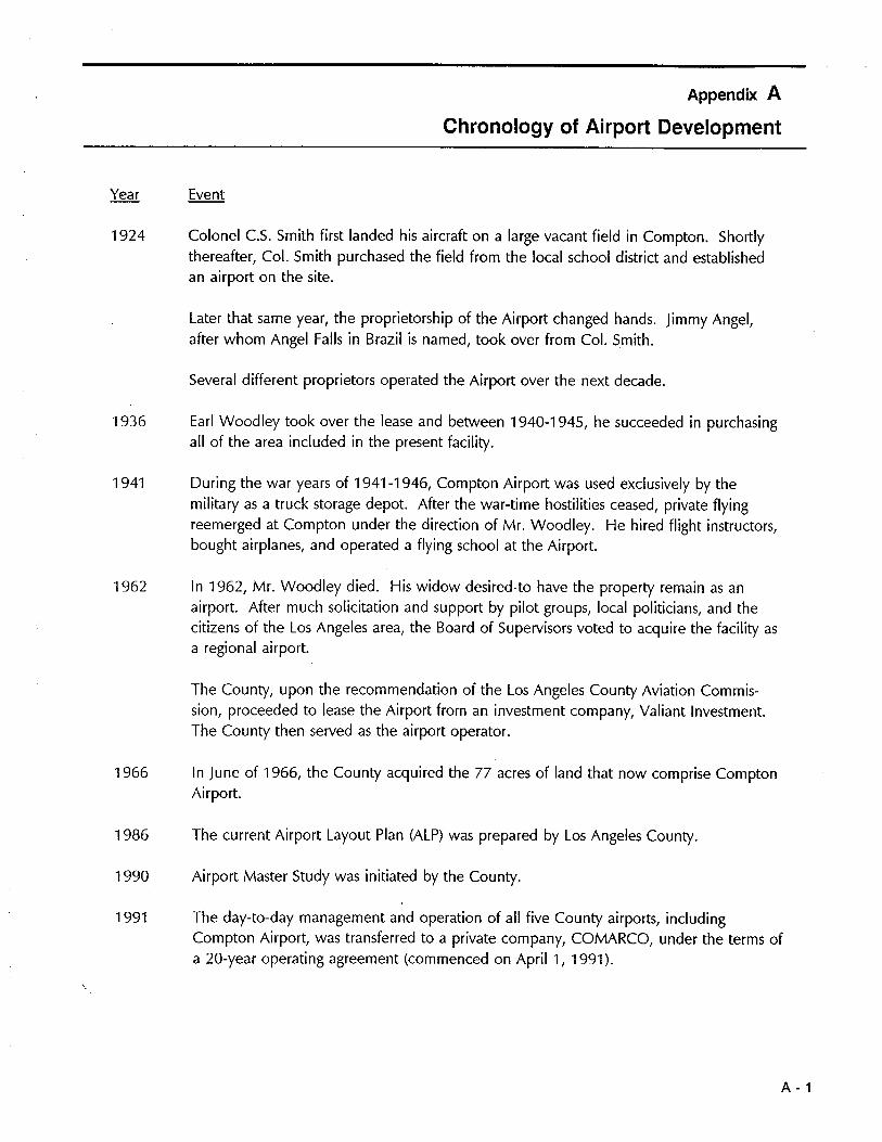
Appendix A
Chronology of Airport Development
Year Event
1924 Colonel C.S. Smith first landed his aircraft on a large vacant field in Compton. Shortlythereafter, Col. Smith purchased the field from the local school district and establishedan airport on the site.
Later that same year, the proprietorship of the Airport changed hands. Jimmy Angel,after whom Angel Falls in Brazil is named, took over from Col. Smith.
Several different proprietors operated the Airport over the next decade.
1936 Earl Woodley took over the lease and between 1940-1945, he succeeded in purchasingall of the area included in the present facility.
1941 During the war years of 1941-1946, Compton Airport was used exclusively by themilitary as a truck storage depot. After the war-time hostilities ceased, private flyingreemerged at Compton under the direction of Mr. Woodley. He hired flight instructors,bought airplanes, and operated a flying school at the Airport.
1962 In 1962, Mr. Woodley died. His widow desired. to have the property remain as an
airport. After much solicitation and support by pilot groups, local politicians, and thecitizens of the Los Angeles area, the Board of Supervisors voted to acquire the facility asa regional airport.
The County, upon the recommendation of the Los Angeles County Aviation Commis-sion, proceeded to lease the Airport from an investment company, Valiant Investment.The County then served as the airport operator.
1966 In June of 1966, the County acquired the 77 acres of land that now comprise ComptonAirport.
1986 The current Airport Layout Plan (ALP) was prepared by Los Angeles County.
1990 Airport Master Study was initiated by the County.
1991 The day-to-day management and operation of all five County airports, includingCompton Airport, was transferred to a private company, COMARCO, under the terms ofa 20-year operating agreement (commenced on April 1, 1991).
A - 1
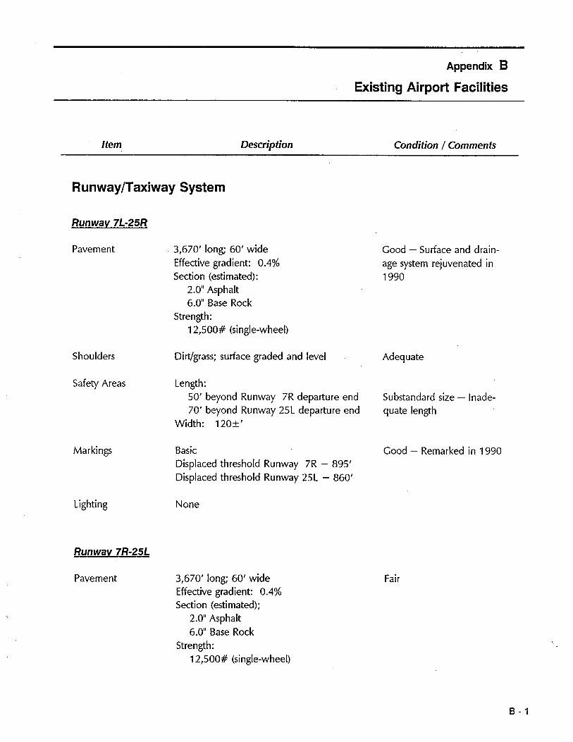
Appendix 8
Existing Airport Facilties
Item Description Conditon / Comments
Runway/Taxiway System
Runwav 7L-25R
Pavement 3,670' long; 60' wideEffective gradient: 0.4%Section (estimated):
2.0" Asphalt6.0" Base Rock
Strength:12,500# (single-wheel)
Good - Surface and drain-age system rejuvenated in1990
Shoulders Dirt/grass; surface graded and level Adequate
Safety Areas Length:50' beyond Runway 7R departure end70' beyond Runway 25L departure end
Width: 120:t'
Substandard size - Inade-
quate length
Markings Basic
Displaced threshold Runway 7R - 895'Displaced threshold Runway 25L - 860'
Good - Remarked in 1990
Lighting None
Runwav 7R-25L
Pavement 3,670' long; 60' wideEffective gradient: 0.4%Section (estimated);
2.0" Asphalt6,0" Base Rock
Strength:12,500# (single-wheel)
Fair
B-1
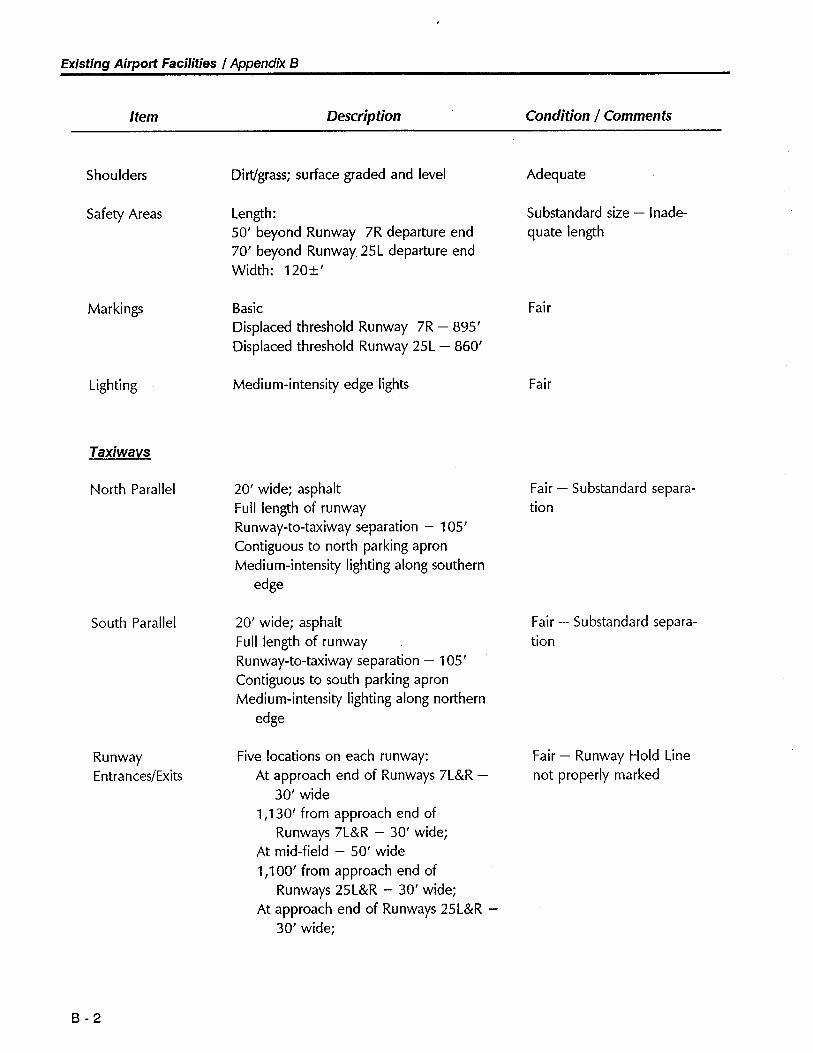
Existing Airport Facilties I Appendix B
Item Description Condition / Comments
Shoulders
Safety Areas
Marki ngs
Lighting
Taxiways
North Parallel
South Parallel
RunwayEntrances/Exits
B-2
Dirtgrass; surface graded and level
Length:50' beyond Runway 7R departure end70' beyond Runway 25L departure endWidth: 120:!'
Basic
Displaced threshold Runway 7R - 895'Displaced threshold Runway 25L - 860'
Medium-intensity edge lights
20' wide; asphaltFull length of runwayRunway-to-taxiway separation - 105'
Contiguous to north parking apronMedium-intensity lighting along southern
edge
20' wide; asphaltFull length of runwayRunway-to-taxiway separation - 105'
Contiguous to south parking apronMedium-intensity lighting along northern
edge
Five locations on each runway:At approach end of Runways 7L&R -
30' wide1,130' from approach end of
Runways 7L&R - 30' wide;At mid-field - 50' wide1,100' from approach end of
Runways 25L&R - 30' wide;At approach end of Runways 25L&R -
30' wide;
Adequate
Substandard size - Inade-
quate length
Fair
Fair
Fair - Substandard separa-tion
Fair - Substandard separa-tion
Fair - Runway Hold Linenot properly marked
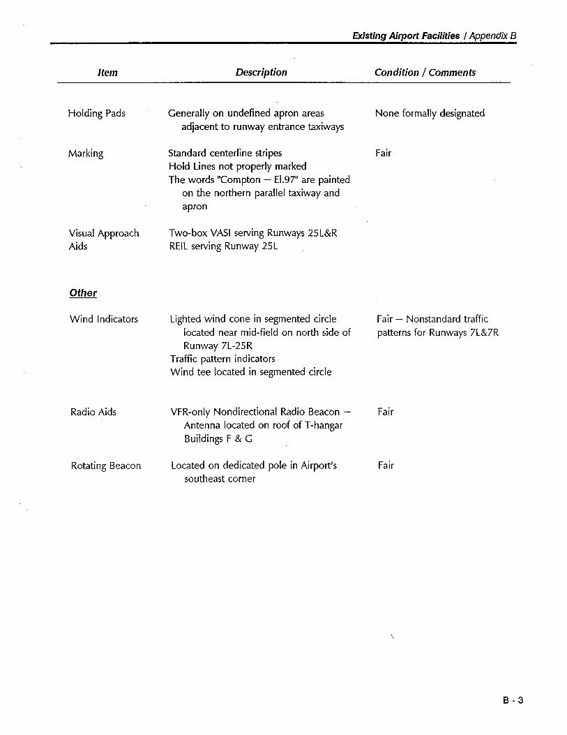
Existing Airport Faciliies I Appendix B
Item Description Condition / Comments
Holding Pads
Marking
Visual ApproachAids
Other
Wind Indicators
Radio Aids
Rotating Beacon
Generally on undefined apron areasadjacent to runway entrance taxiways
Standard centerline stripesHold Lines not properly markedThe words "Compton - E1.97" are painted
on the northern parallel taxiway andapron
Two-box VAS I serving Runways 25L&RREIL serving Runway 25L
Lighted wind cone in segmented circlelocated near mid-field on north side ofRunway 7L-25R
Traffic pattern indicatorsWind tee located in segmented circle
VFR-only Nondirectional Radio Beacon -Antenna located on roof of T-hangarBuildings F & G
Located on dedicated pole in Airport'ssoutheast corner
None formally designated
Fair
Fair - Nonstandard trafficpatterns for Runways 7L&7R
Fair
Fair
B-3
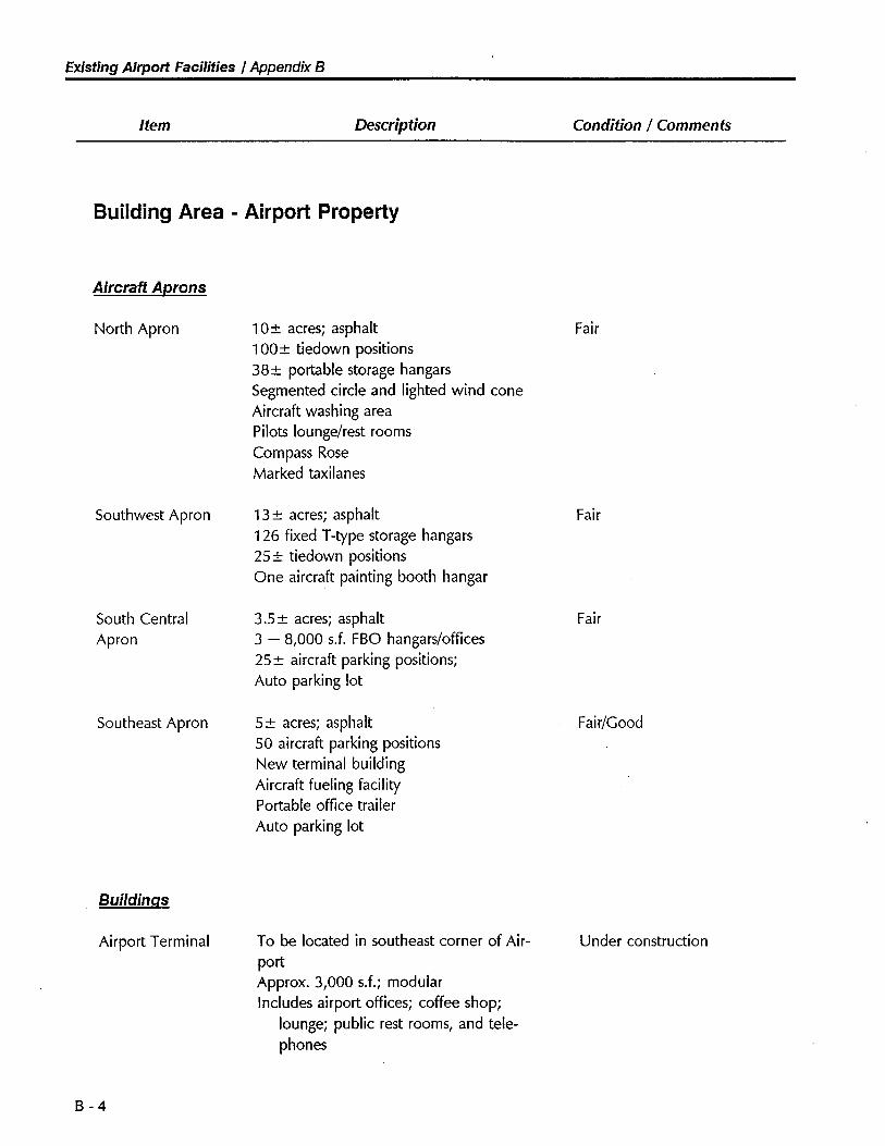
Existing Airport Faciliies I Appendix B
Item Description Conditon / Comments
Building Area - Airport Property
Aircraft Aprons
North Apron
Southwest Apron
South CentralApron
Southeast Apron
Buildinas
Airport Terminal
B - 4
10:t acres; asphalt
1 OO:! tiedown positions38:t portble storage hangars
Segmented circle and lighted wind coneAircraft washing areaPilots lounge/rest roomsCompass Rose
Marked taxilanes
13:! acres; asphalt
126 fixed T-type storage hangars25:t tiedown positionsOne aircraft painting booth hangar
3.s:t acres; asphalt
3 - 8,000 sJ. FBO hangars/offces
25:t aircraft parking positions;
Auto parking lot
5:t acres; asphalt
50 aircraft parking positionsNew terminal buildingAircraft fueling facilityPortable office trailerAuto parking lot
To be located in southeast corner of Air-portApprox. 3,000 sJ.; modularIncludes airport offices; coffee shop;
lounge; public rest rooms, and tele-phones
Fair
Fair
Fair
Fair/Good
Under construction
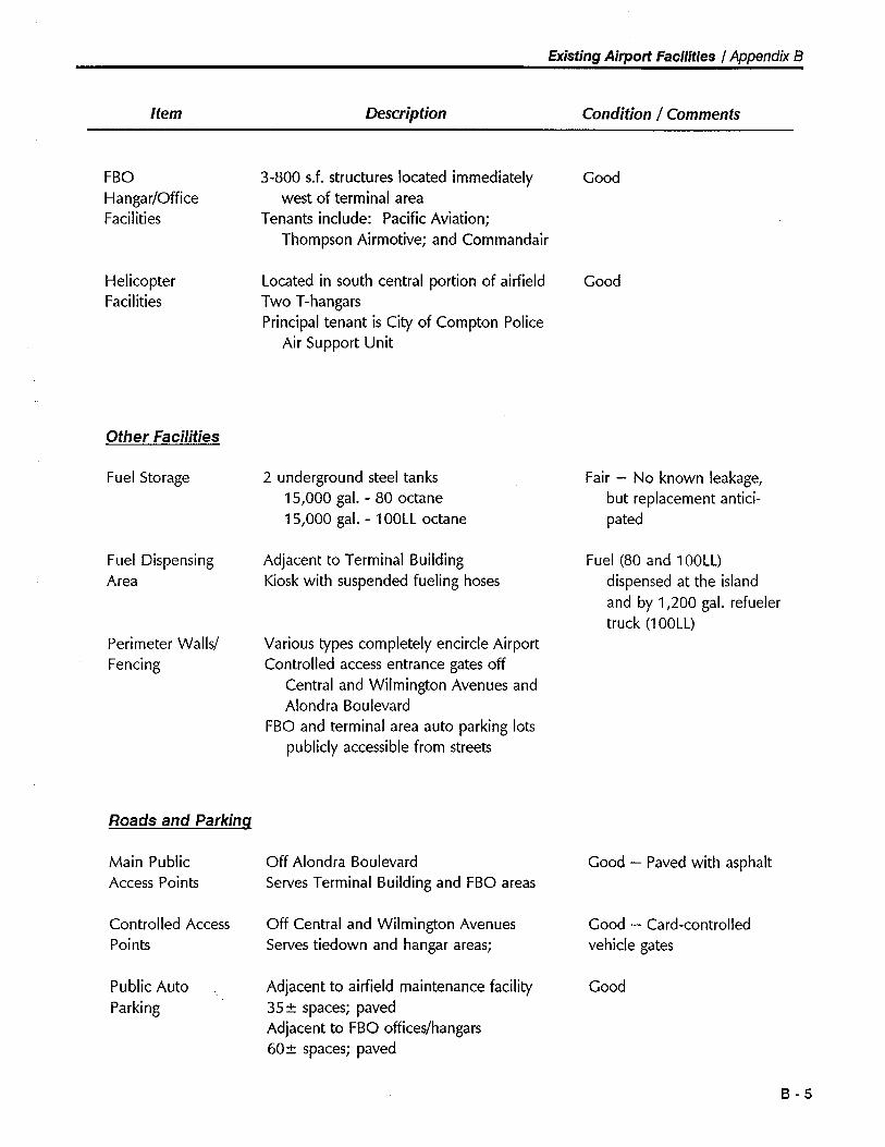
Existing Airport Facilties I Appendix B
Item Description Condition / Comments
FBOHangar/OfficeFacilities
HelicopterFacilities
Other Facilties
Fuel Storage
Fuel DispensingArea
Perimeter Walls/
Fencing
Roads and Parkinq
Main PublicAccess Points
Controlled Access
Points
Public AutoParking
3-800 sJ. structures located immediatelywest of terminal area
Tenants include: Pacific Aviation;Thompson Airmotive; and Commandair
Located in south central portion of airfieldTwo T-hangarsPrincipal tenant is City of Compton Police
Air Support Unit
2 underground steel tanks15,000 gal. - 80 octane15,000 gal. - 100LL octane
Adjacent to Terminal BuildingKiosk with suspended fueling hoses
Various types completely encircle AirportControlled access entrance gates off
Central and Wilmington Avenues andAlondra Boulevard
FBO and terminal area auto parking lotspublicly accessible from streets
Off Alondra BoulevardServes Terminal Building and FBO areas
Off Central and Wilmington AvenuesServes tiedown and hangar areas;
Adjacent to airfield maintenance facility35:! spaces; paved
Adjacent to FBO offices/hangars60:t spaces; paved
Good
Good
Fair - No known leakage,but replacement antici-pated
Fuel (80 and 100LL)dispensed at the islandand by 1,200 gal. refuelertruck (100LL)
Good - Paved with asphalt
Good - Card-controlledvehicle gates
Good
B - 5
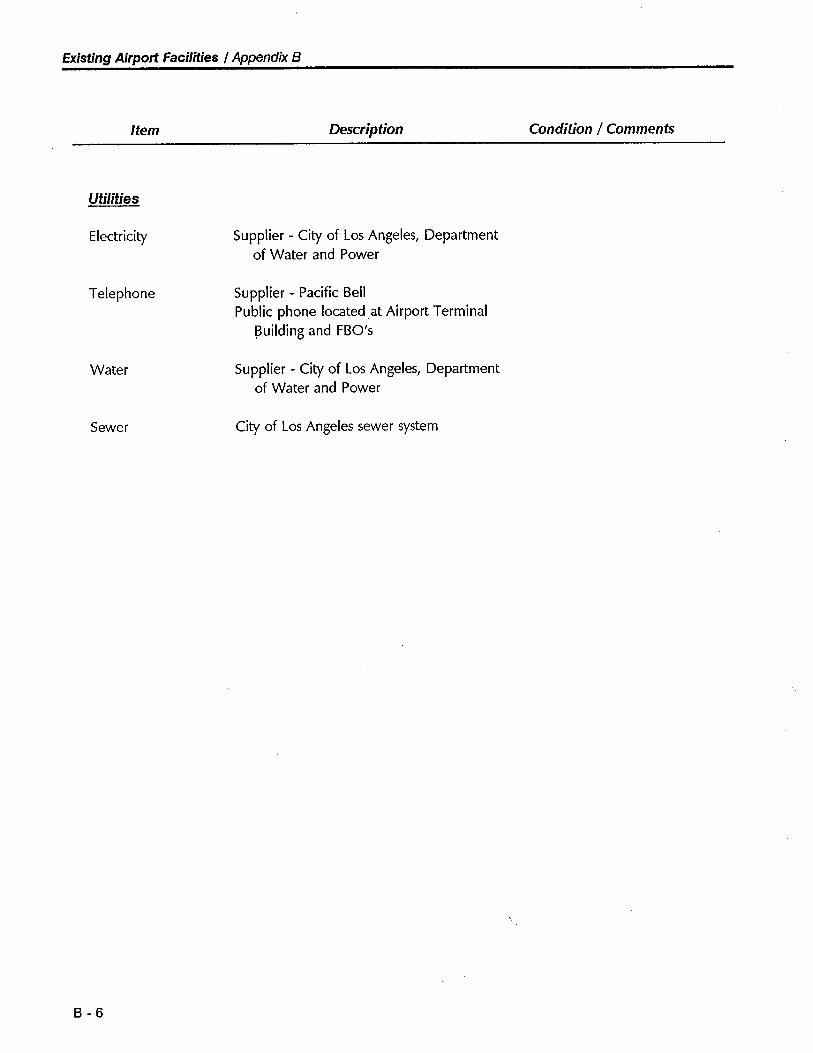
Existing Airport Faciliies I Appendix B
Item Description Condition / Comments
Utilties
Electricity Supplier - City of Los Angeles, Departmentof Water and Power
Telephone Supplier - Pacific BellPublic phone located at Airport Terminal
!3uilding and FBO's
Water Supplier - City of Los Angeles, Departmentof Water and Power
Sewer City of Los Angeles sewer system
B - 6
Appendix C
Summary of Airport User Survey Questionnaires
Early in the Master Plan study effort (September 1990), a survey questionnaire was distributed bymail to every aircraft owner based at Compton Airport and known to the airport management.More than 350 questionnaires were distributed and 75 responses were received. This response rate(21 %) is considered to be good for this type of survey.
A summary of the questionnaire responses follows. Note that percentages in some cases do nottotal 1 00% due to multiple responses.
C - 1
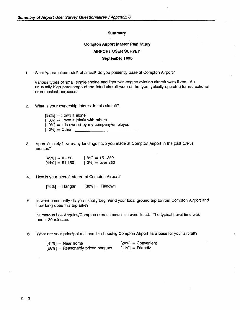
Summary of Airport User Survey Questionnaires / Appendix C
Summary
Compton Airport Master Plan Study
AIRPORT USER SURVEY
September 1990
1. What "year/make/model. of aircraft do you presently base at Compton Airport?
Various types of small single-engine and light twin-engine aviation aircraft were listed. Anunusually high percentage of the listed aircraft were of the type typically operated for recreationalor enthusiast purposes.
2. What is your ownership interest in this aircraft?
(92%) = I own it alone.( 8%) = I own it jointly with others.( 0%) = It is owned by my company/employer.( 0%) = Other:
3. Approximately how many landings have you made at Compton Airport in the past twelvemonths?
(45%) = 0 - 50(44%) = 51-150
( 8%) = 151-350( 3%) = over 350
4. How is your aircraft stored at Compton Airport?
(70%) = Hangar (30%) = Tiedown
5. In what community do you usually begin/end your local ground trip to/from Compton Airport andhow long does this trip take?
Numerous Los Angeles/Compton area communities were listed. The typical travel time wasunder 30 minutes.
6. What are your principal reasons for choosing Compton Airport as a base for your aircraft?
(41%) = Near home(28%) = Reasonably priced hangars
(20%) = Convenient
(11%) = Friendly
C - 2
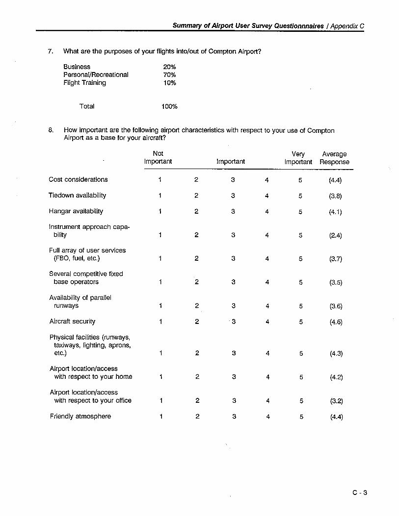
Summary of Airport User Survey Questionnnaires / Appendix C
7. What are the purposes of your flights int%ut of Compton Airport?
Business 20%Personal/Recreational 70%Flight Training 10%
Total 100%
8. How important are the following airport characteristics with respect to your use of ComptonAirport as a base for your aircraft?
Not Very AverageImportant Important Important Response
Cost considerations 1 2 3 4 5 (4.4)
Tiedown availabilty 1 2 3 4 5 (3.8)
Hangar availabilty 1 2 3 4 5 (4.1)
Instrument approach capa-bilty 1 2 3 4 5 (2.4)
Full array of user services(FBO, fuel, etc.) 1 2 3 4 5 (3.7)
Several competitive fixedbase operators 1 2 3 4 5 (3.5)
Availabilty of parallelrunways 1 2 3 4 5 (3.6)
Aircraft security 1 2 3 4 5 (4.6)
Physical facilties (runways,taxiways, lighting, aprons,etc.) 1 2 3 4 5 (4.3)
Airport location/accesswith respect to your home 1 2 3 4 5 (4.2)
Airport location/accesswith respect to your office 1 2 3 4 5 (3.2)
Friendly atmosphere 1 2 3 4 5 (4.4)
C - 3
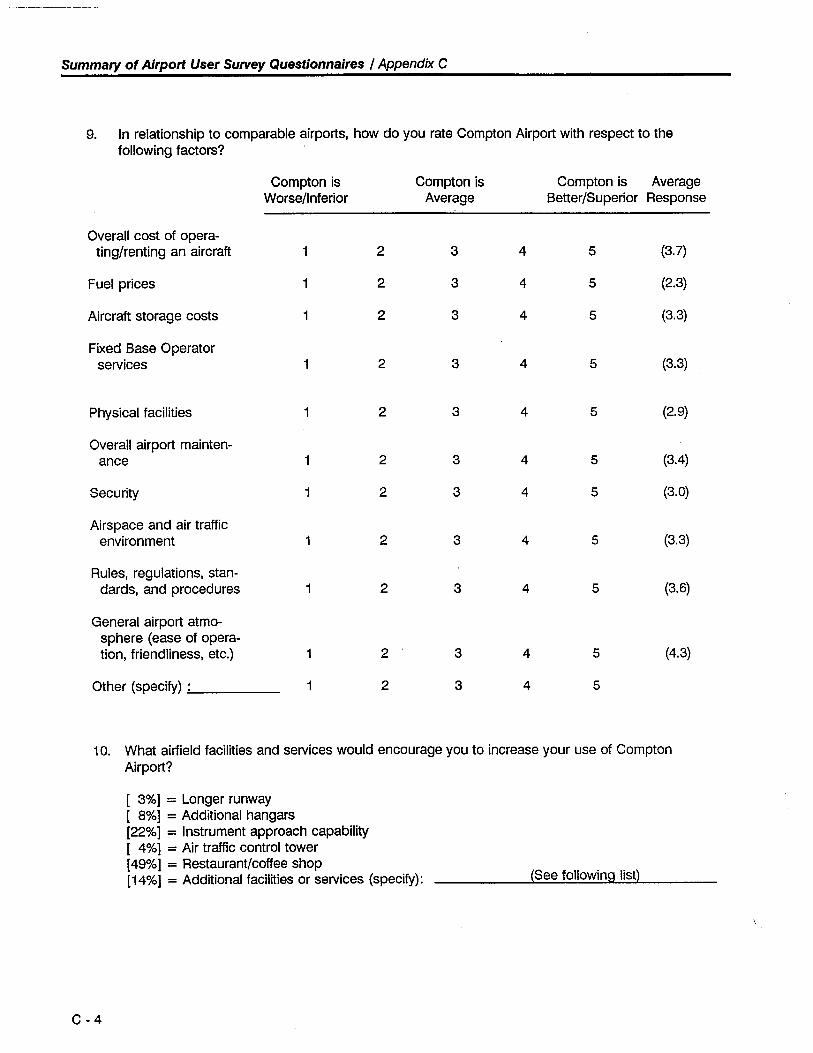
Summary of Airport User Survey Questionnaires / Appendix C
9. In relationship to comparable airports, how do you rate Compton Airport with respect to thefollowing factors?
Compton is Compton is Compton is AverageWorse/Inferior Average Better/Superior Response
Overall cost of opera-ting/rentingan aircraft 1 2 3 4 5 (3.7)
Fuel prices 1 2 3 4 5 (2.3)
Aircraft storage costs 1 2 3 4 5 (3.3)
Fixed Base Operatorservices 1 2 3 4 5 (3.3)
Physical facilties 1 2 3 4 5 (2.9)
Overall airport mainten-ance 1 2 3 4 5 (3.4)
Security 1 2 3 4 5 (3.0)
Airspace and air trafficenvironment 1 2 3 4 5 (3.3)
Rules, regulations, stan-dards, and procedures 1 2 3 4 5 (3.6)
General airport atmo-sphere (ease of opera-tion, friendliness, etc.) 1 2 3 4 5 (4.3)
Other (specify) : 1 2 3 4 5
10. What airfield facilties and services would encourage you to increase your use of ComptonAirport?
( 3%) = Longer runway
( 8%) = Additional hangars
(22%) = Instrument approach capabilty( 4%) = Air traffic control tower(49%) = Restaurant/coffee shop(14%) = Additional facilities or services (specify): (See following list)
C - 4
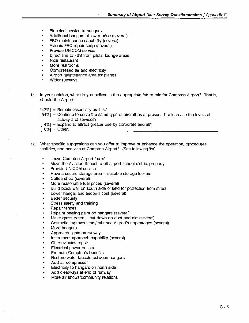
Summaiy of Airport User Survey Questionnnaires / Appendix C
· Electrical service to hangars
· Additional hangars at lower price (several)
· FBO maintenance capabilty (several)· Avionic FBO repair shop (several)
· Provide UNICOM service· Direct line to FSS from pilots' lounge areas
· Nice restaurant
· More restrooms· Compressed air and electricity· Airport maintenance area for planes
Wider runways
11. In your opinion, what do you believe is the appropriate future role for Compton Airport? That is,should the Airpbrt: .(42%) = Remain essentially as it is?(54%) = Continue to serve the same type of aircraft as at present, but increase the levels of
activity and services?4%) = Expand to attract greater use by corporate aircraft?0%) = Other:
12. What specific suggestions can you offer to improve or enhance the operation, procedures,facilities, and services at Compton Airport? (See following list)
Leave Compton Airport Mas is.· Move the Aviation School to off-airport school district property· Provide UNICOM service
· Have a secure storage area - suitable storage lockers· Coffee shop (several)
· More reasonable fuel prices (several)· Build block wall on south side of field for protection from street
Lower hangar and tiedown cost (several)· Better security
· Stress safety and training
Repair fencesRepaint peeling paint on hangars (several)
· Make grass green - cut down on dust and dirt (several)Cosmetic improvements/enhance Airport's appearance (several)
· More hangars· Approach lights on runway
Instrument approach capabilty (several)· Offer avionics repair
· Electrical power outlets
· Promote Compton's benefits
· Restore water faucets between hangars
Add air compressorElectricity to hangars on north side
· Add clearways at end of runway· More air shows/community relations
C - 5
Appendix D
Acquisition of Additional Land Area
Introduction
Over the years, it has been suggested that Los Angeles County or private interests acquire additionalland area contiguous to Compton Airport to permit the expansion of the Airport's building area andaircraft storage capacity. The only area of land that would readily facilitate such expansion is thestrip of residentially developed land located between the Airport's northern boundary and 156thStreet.
The purpose of this discussion paper is to 1) review the advantages and disadvantages associatedwith the possible acquisition of all or a part of this land area; and 2) offer the Consultant's conclu-sions regarding any such acquisition.
Description of Land Area and Improvements
The subject land area is a long rectangular strip of land (approximately 9.5 acres) that is fullydeveloped and in high-density residential use (see Figure D-1). Seventy-three single-family housesare located on the 3,800' x 110' strip of land. The parcels front on 156th Street and are borderedin the back by the Airport's northern boundary walL. The houses are 30-40 years old.
The 3,800' strip of land is divided into three roughly equal-length segments. One 1,400' longsegment extends from Central Avenue east to Tajauta Avenue, the second 1,200' long segmentextends from Tajauta Avenue to Dwight Avenue, and the third 1,200' long segment extends fromDwight Avenue to Wilmington Avenue. In previous discussions, both the City and County haveindicated that these individual segments are the smallest land area increments that should beconsidered for acquisition. In this way, no isolated parcels would remain, and the neighborhood'sbasic configuration would be retained.
At the time of this analysis, the asking prices for representative parcels (with fixed improvements) inthis area were in the $80,000-$90,000 range.
Discussion
The two basic questions related to this discussion are:
· Should all, a portion, or none of this land area be acquired to support Airport expansion anddevelopment?
D - 1
Acquisition of Additional Land Area / Appendix D
· Can all, a portion, or none of this land area be acquired in a cost-effective and socially-accept-able manner?
The advantages and disadvantages associated with the potential acquisition of the subject land areaare summarized in Table D-1.
As indicated in the Airport Activity Forecast section of the Compton Airport Master Plan Report, thenumber of aircraft based at the Airport is projected to total 500 by the year 2010. With appropri-ate modifications to the Airport's existing runway/taxiway system and building area, all of theseaircraft can be accommodated within the Airport's existing boundaries. Therefore, on the basis offorecasted general aviation demand, there appears to be no requirement for acquisition of addition-al Airport property during the 20-year planning timeframe. However, beyond the 20-year planningtimeframe, additional land area may be required to accommodate aeronautical demand.
In addition, it is estimated that acquisition of the subject properties and the preparation of the basicsites for hangar development would cost a minimum of $100,000 per hangar unit. The com-putational basis for this estimate is presented in Table D-2.
Conclusions
While it would be advantageous to the general public and aviation community to acquire additionalland area for possible future expansion and development of Compton Airport, the various "costs" -both financially and socially - of doing so at this time are significant. In addition, on the basis ofthe 20-year Airport Activity Forecast, there is no immediate need for the acquisition. However, anyfuture change in the Airport's operational role and/or demand characteristics could require an in-depth reevaluation of the acquisition's merit.
In light of the fully-developed residential nature of the subject land area, no future change in landuse in this area is envisioned. Therefore, the option of acquiring the subject land area, should itprove advantageous at some point in the future, is not lost, but merely delayed. However, it canbe anticipated that with the normal escalation in property values, future acquisition of the subjectland area will be significantly more costly and, thus, more difficult to justify on a cost/benefit basis.
Accordingly, it is suggested that the subject land area not be acquired at this time. The option ofacquiring the subject land area should, however, be preserved for future consideration. Thedevelopment of the basic airfield and northside airport building area should be conducted in such amanner as to not preclude future access to and ultimate development of the subject land area forAirport-support purposes.
D - 2
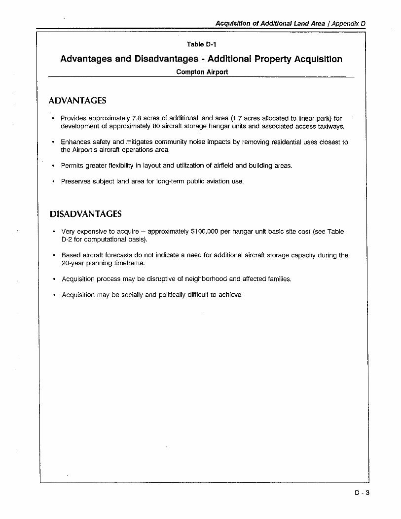
Acquisition of Additional Land Area / Appendix D
Table D-1
Advantages and Disadvantages - Additional Property AcquisitionCompton Airport
ADVANTAGES
· Provides approximately 7.8 acres of additional land area (1.7 acres allocated to linear park) fordevelopment of approximately 80 aircraft storage hangar units and associated access taxiways.
· Enhances safety and mitigates community noise impacts by removing residential uses closest tothe Airport's aircraft operations area.
· Permits greater flexibilty in layout and utilization of airfield and building areas.
. Preserves subject land area for long-term public aviation use.
DISADV ANT AGES
. Very expensive to acquire - approximately $100,000 per hangar unit basic site cost (see TableD-2 for computational basis).
· Based aircraft forecasts do not indicate a need for additional aircraft storage capacity during the20-year planning timeframe.
· Acquisition process may be disruptive of neighborhood and affected familes.
· Acquisition may be socially and politically difficult to achieve.
D - 3
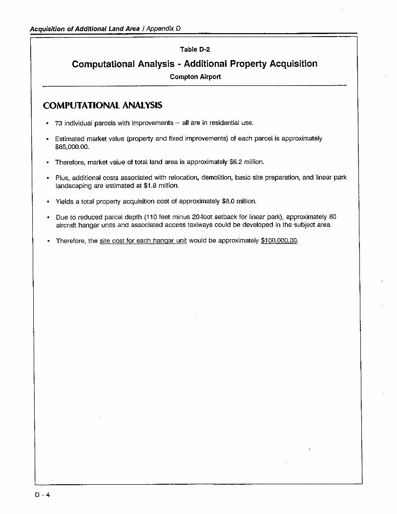
Acquisition of Additional Land Area / Appendix D
Table D-2
Computational Analysis - Additional Property AcquisitionCompton Airport
COMPUTATIONAL ANALYSIS
· 73 individual parcels with improvements - all are in residential use.
. Estimated market value (property and fixed improvements) of each parcel is approximately
$85,000.00.
· Therefore, market value of total land area is approximately $6.2 millon.
· Plus, additional costs associated with relocation, demolition, basic site preparation, and linear parklandscaping are estimated at $1.8 milion.
· Yields a total propert acquisition cost of approximately $8.0 millon.
· Due to reduced parcel depth (110 feet minus 20-foot setback for linear park), approximately 80aircraft hangar units and associated access taxiways could be developed in the subject area.
· Therefore, the site cost for each hanqar unit would be approximately $100,000.00.
D - 4
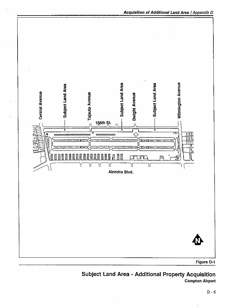
Acquisition of Additional Land Area I Appendix D
m !..CCCC
CD CD CD 't:J "C :J :J CC C C C ~CD ~ CD CD
~~
~ ~ ~e CI -'E
- .c "E- :J a :Jc :J .~8 ~.
tJ
L1\
-0.J (
l:=::
Alondra Blvd.
~Figure D-1
Subject Land Area - Additional Property AcquisitionCompton Airport
D - 5
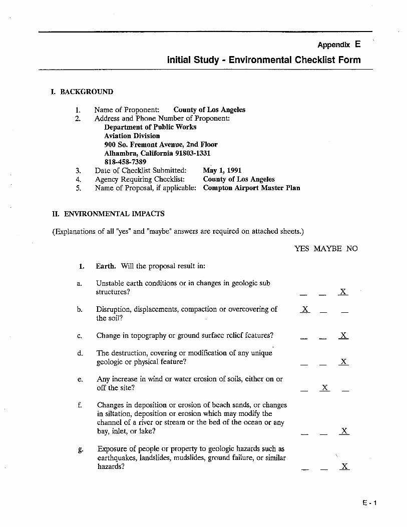
Appendix E
Initial Study - Environmental Checklist Form
I. BACKGROUND
1. Name of Proponent: County of Los Angeles2. Address and Phone Number of Proponent:
Department of Public WorksAviation Division
900 So. Fremont Avenue, 2nd FloorAlhambra, California 91803-1331
818-458-73893. Date of Checklist Submitted: May 1, 1991
4. Agency Requiring Checklist: County of Los Angeles
5. Name of Proposal, if applicable: Compton Airport Master Plan
II. ENVRONMENTAL IMPACTS
(Exlanations of all "yes" and "maybe" answers are required on attached sheets.)
YES MAYBE NO
1. Earth. Wil the proposal result in:
a. Unstable earth conditions or in changes in geologic substructures? x
b. Disruption, displacements, compaction or overcovering ofthe soil?
xc. Change in topography or ground surface relief features? xd. The destruction, covering or modification of any unique
geologic or physical feature? xe. Any increase in wind or water erosion of soils, either on or
off the site? xf. Changes in deposition or erosion of beach sands, or changes
in siltation, deposition or erosion which may modify thechannel of a river or stream or the bed of the ocean or anybay, inlet, or lake? x
g. Exosure of people or property to geologic hazards such asearthquakes, landslides, mudslides, ground failure, or similarhazards? x
E - 1
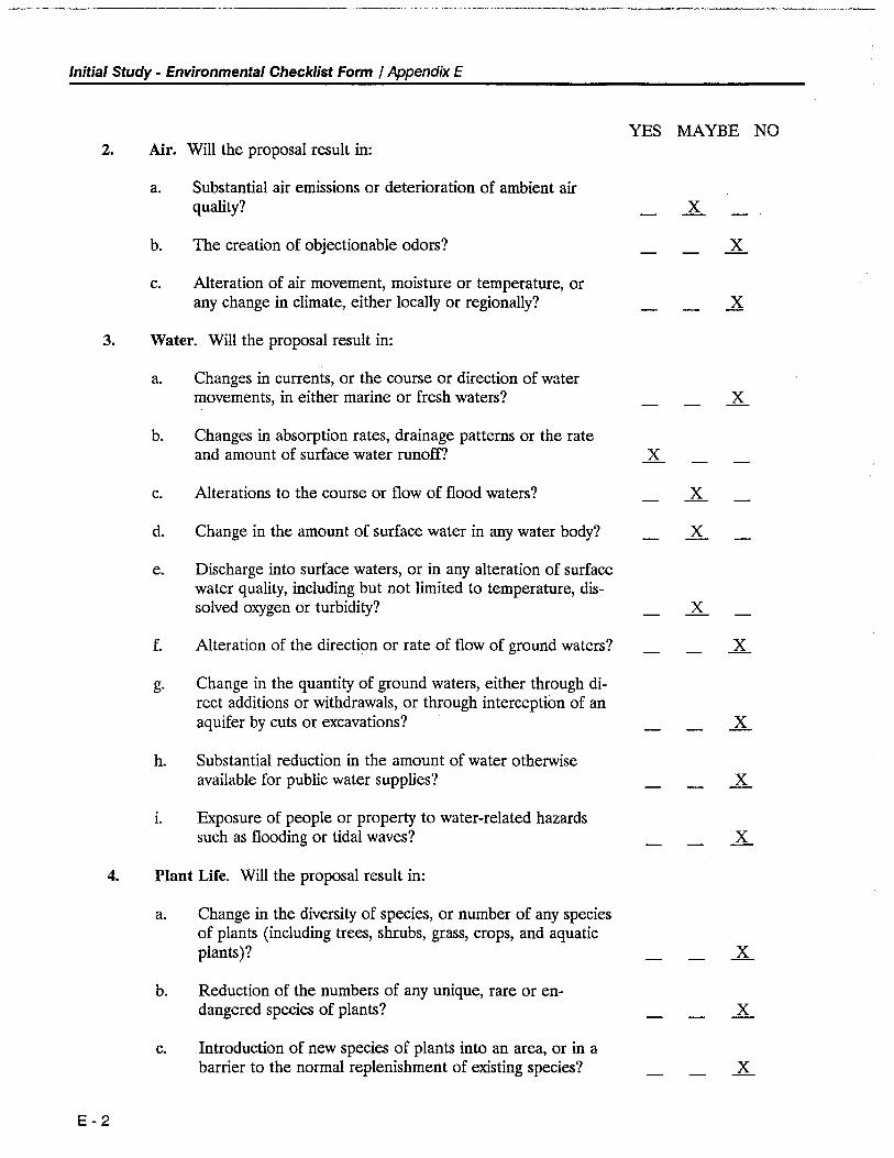
Initial Study - Environmental Checklist Form / Appendix E
YES MAYBE NO2. Air. Wil the proposal result in:
a. Substantial air emissions or deterioration of ambient airquality? X
b. The creation of objectionable odors? Xc. Alteration of air movement, moisture or temperature, or
any change in climate, either locally or regionally? X
3. Water. Wil the proposal result in:
a. Changes in currents, or the course or direction of watermovements, in either marine or fresh waters? X
b. Changes in absorption rates, drainage patterns or the rateand amount of surface water runoff X
c. Alterations to the course or flow of flood waters? Xd. Change in the amount of surface water in any water body? Xe. Discharge into surface waters, or in any alteration of surface
water quality, including but not limited to temperature, dis-solved oxygen or turbidity? X
f. Alteration of the direction or rate of flow of ground waters? Xg. Change in the quantity of ground waters, either through di-
rect additions or withdrawals, or through interception of anaquifer by cuts or excavations? X
h. Substantial reduction in the amount of water otherwseavailable for public water supplies'! X
1. Exosure of people or property to water-related hazardssuch as flooding or tidal waves? X
4. Plant Lire. Wil the proposal result in:
a. Change in the diversity of species, or number of any speciesof plants (including trees, shrubs, grass, crops, and aquaticplants)? X
b. Reduction of the numbers of any unique, rare or en-dangered species of plants? X
c. Introduction of new species of plants into an area, or in abarrer to the normal replenishment of existing species? X
E - 2
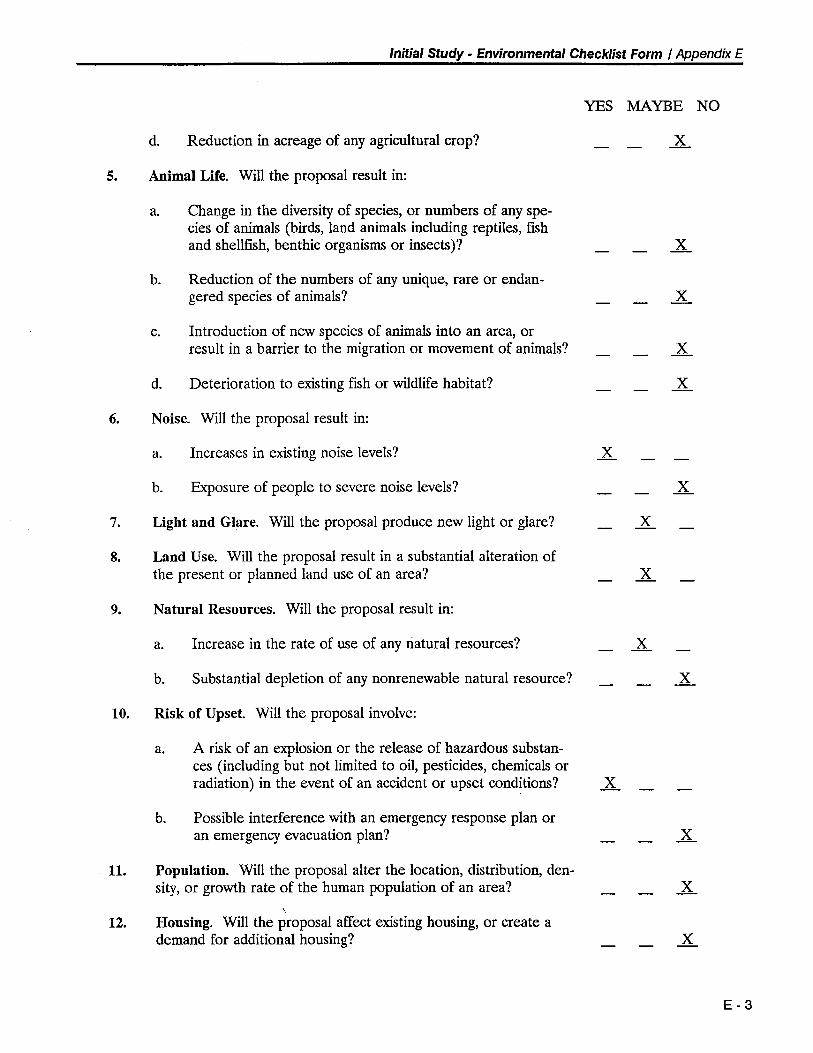
Initial Study - Environmental Checklist Form / Appendix E
YES MAYBE NO
d. Reduction in acreage of any agricultural crop? X.
5. Animal Life. Wil the proposal result in:
a. Change in the diversity of species, or numbers of any spe-cies of animals (birds, land animals including reptiles, fih
and shellfih, benthic organisms or insects)? X.
b. Reduction of the numbers of any unique, rare or endan-gered species of animals? X.
c. Introduction of new species of animals into an area, orresult in a barrier to the migration or movement of animals? X.
d. Deterioration to existing fish or wildlife habitat? X.
6. Noise. Wil the proposal result in:
a. Increases in existing noise levels? Xb. Exosure of people to severe noise levels? X.
7. Light and Glare. Wil the proposal produce new light or glare? X.
8. Land Use. Wil the proposal result in a substantial alteration ofthe present or planned land use of an area? X.
9. Natural Resources. Wil the proposal result in:
a. Increase in the rate of use of any natural resources? Xb. Substantial depletion of any nonrenewable natural resource? X
10. Risk of Upset. Wil the proposal involve:
a. A risk of an explosion or the release of hazardous substan-ces (including but not limited to oil, pesticides, chemicals orradiation) in the event of an accident or upset conditions? X
b. Possible interference with an emergency response plan oran emergency evacuation plan? X
11. Population. Wil the proposal alter the location, distribution, den-sity, or growth rate of the human population of an area? X.
12. Housing. Wil the proposal affect existing housing, or create ademand for additional housing? X.
E - 3
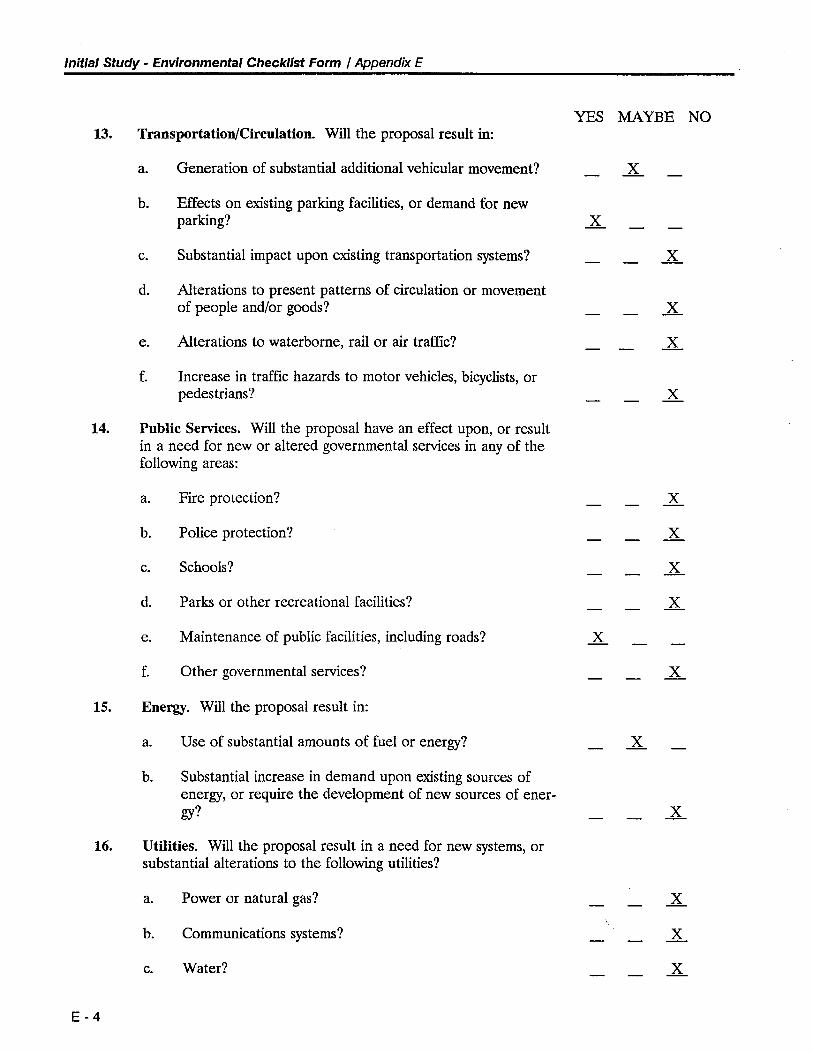
Initial Study - Environmental Checklist Form / Appendix E
YES MAYBE NO13. Transportation/Circulation. Wil the proposal result in:
a. Generation of substantial additional vehicular movement? Xb. Effects on existing parking facilities, or demand for new
parking? Xc. Substantial impact upon existing transportation systems? Xd. Alterations to present patterns of circulation or movement
of people and/or goods? Xe. Alterations to waterborne, rail or air traffic? Xf. Increase in traffic hazards to motor vehicles, bicyclists, or
pedestrians? X
14. Public Servces. Wil the proposal have an effect upon, or resultin a need for new or altered governmental servces in any of thefollowing areas:
a. Fire protection? X
b. Police protection? X
c. Schools? Xd. Parks or other recreational facilities? Xe. Maintenance of public facilities, including roads? Xf. Other governmental servces? X
15. Energ. Wil the proposal result in:
a. Use of substantial amounts of fuel or energy? Xb. Substantial increase in demand upon existing sources of
energy, or require the development of new sources of ener-gy? X
16. Utiities. Wil the proposal result in a need for new systems, or
substantial alterations to the following utilities?
a. Power or natural gas? Xb. Communications systems? Xc. Water? X
E - 4
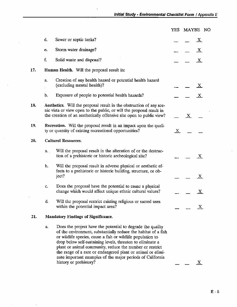
Initial Study - Environmental Checklist Form / Appendix E
YES MAYBE NO
d. Sewer or septic tanks? Xe. Storm water drainage? Xf. Solid waste and disposal? X
17. Human Health. Wil the proposal result in:
a. Creation of any health hazard or potential health hazard(excluding mental health)? X
b. Exosure of people to potential health hazards? X18. Aesthetics. Wil the proposal result in the obstruction of any sce-
nic vista or view open to the public, or will the proposal result inthe creation of an aesthetically offensive site open to public view? X
19. Recreation. Wil the proposal result in an impact upon the quali-ty or quantity of existing recreational opportunities? X
20. Cultural Resources.
a. Wil the proposal result in the alteration of or the destruc-tion of a prehistoric or historic archeological site? X
b. Wil the proposal result in adverse physical or aesthetic ef-fects to a prehistoric or historic building, structure, or ob-ject? X
c. Does the proposal have the potential to cause a physicalchange which would affect unique ethnic cultural values? X
d. Wil the proposal restrict existing religious or sacred useswithin the potential impact area? X
21. Mandatory Findings of Significance.
a. Does the project have the potential to degrade the qualityof the environment, substantially reduce the habitat of a ffshor wildlife species, cause a ffsh or wildlife population todrop below self-sustaining levels, threaten to eliminate aplant or animal community, reduce the number or restrictthe range of a rare or endangered plant or animal or elimi-nate important examples of the major periods of Californiahistory or prehistory? X
E - 5
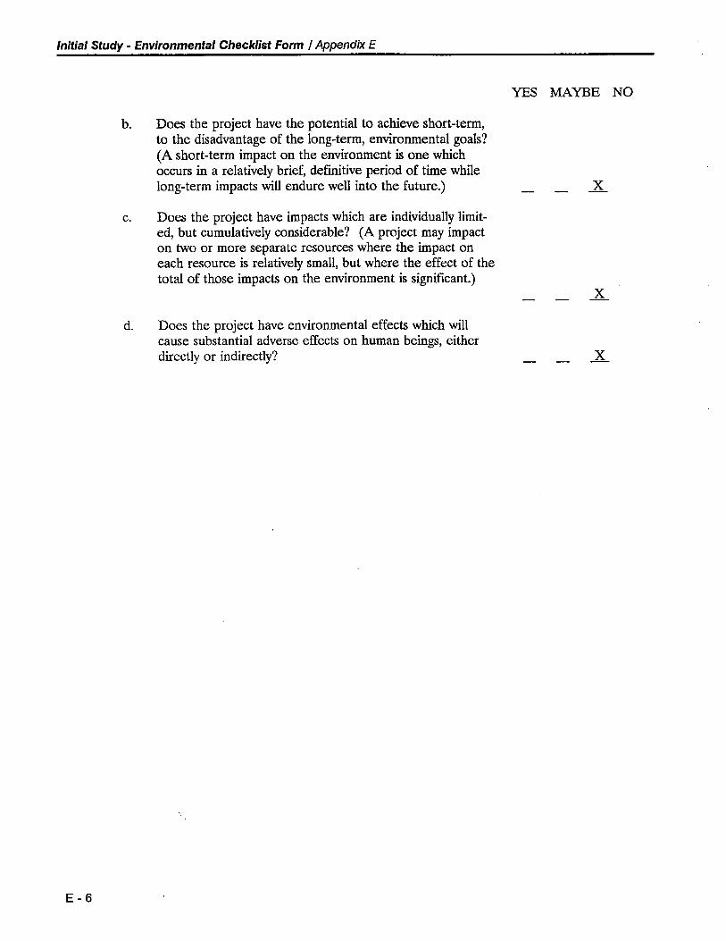
Initial Study - Environmental Checklist Form / Appendix E
E - 6
b. Does the project have the potential to achieve short-term,to the disadvantage of the long-term, envionmental goals?(A short-term impact on the environment is one whichoccurs in a relatively brief, definitive period of time whilelong-term impacts will endure well into the future.)
c. Does the project have impacts which are individually limit-ed, but cumulatively considerable? (A project may impacton two or more separate resources where the impact oneach resource is relatively small, but where the effect of thetotal of those impacts on the environment is signifcant.)
d. Does the project have environmental effects which willcause substantial adverse effects on human beings, eitherdirectly or indirectly?
YES MAYBE NO
x
..
x
Initial Study - Environmental Checklist Form / Appendix E
III. DISCUSSION OF ENVRONMENTAL EVALUATION
General Note: The Compton Airport Master Plan is a comprehensive assessment of the faciltyand servce enhancements required to see the Aiort fulfill its public servce role through theyear 2010. This Master Plan builds upon the Airport Layout Plan approved by the County of LosAngeles in 1966.
The following key findings and recommendations are identified in the Master Plan:
· The operational/servce role of the Airport is not expected to differ signifcantly from therole the Airport has served since its first use in 1924.
· Within the initial five-year period, the runways' pavement ends are programmed to be
relocated inward approximately 230 feet to accommodate the FAA-standard Object FreeArea. This relocation wil result in a reduction in published runway length from the current3,670 feet to an ultimate length of 3,190 feet.
· Due to anticipated future demand for additional aircraft basing capacity, it is anticipated thatthe current parallel runway system (Runways 7L-25R and 7R-25L) will be converted to asingle runway configuration (Runway 7-25) within the five- to ten-year timeframe.
The sum of the airfield development proposed in the Master Plan represents a mitigatable impacton the environment. The appropriate mitigation actions are identified in the Master Plan.
The following is submitted in response to the preceding environmental impact checklist:
1 a The construction activities which would occur as a result of implementation of thisPlan would consist principally of paving and erection of single-story structures. Noneof these activities are anticipated to create unstable earth conditions or have any effectupon the underlying geologic structures.
1 b The construction of additional taxways and ramp areas will result in covering the exist-ing unirrigated areas, which are sparsely covered with native plant species. None ofthe project site is in its native state. Most of the site has been previously alteredduring construction of the original airfield or development of adjacent uses.
1 c The area to be developed is essentially leveL. There will be no significant changes intopography because of construction activity.
1 d The airport site is a flat, undifferentiated plane. No unique geologic or physicalfeatures have been identified.
1 e,f New development wil result in creation of additional impervous surfaces and, there-fore, additional storm water run-off. The engineering design of the new facilitiesshould include provisions for handling run-off to prevent an increase in erosion. Site
watering and other techniques should be used during construction to minimize dustand wind erosion.
1 g There are no known faults on or near the project area.
E -7
Initial Study - Environmental Checklist Form / Appendix E
2 a
2 b
2 c
3 a
3 b-d
3 e
3 f-h
3 i
4 a-c
4 d
5 a-c
E - 8
The forecasted increases in aircraft operations will increase the amount of emisionsattributable to the Aiport (both directly by aircraft and indirectly by automobiles
associated with airport users). However, the total amount of emissions will not have asignificant effect on regional air quality. The amount of emissions is negligible com-pared to the much larger effect attributable to the exiting and planned urbanizeddevelopment in the area.
Aircraft engines, especially turbine engines, produce exhaust odors which many peoplefind objectionable. However, the volume of use by turbine aircraft, which are typicallythe most objectionable, is forecast to be insignifcant and no significant change willoccur with the other engine tyes.
Future development at the Airport is of such limited scale that it is not anticipated tocause any change in climate.
Although the project will increase the amount of storm run-off, it will not change thecourse or direction of water movement.
As described in le, the planned addition of pavement and structures will increase theamount of storm runoff. This will result in a minor increase in flows of water into theexisting storm water drainage system.
In a manner similar to roads, the run-off from airfield pavement can be expected tocontain materials associated with the vehicles which use it (aircraft, automobiles, andtrucks). The amount of these materials is small and no mitigation measure is pro-posed. Accidental spilage associated with aircraft fueling operations has a greaterpotential to affect surface water quality. Current state and federal hazardous materialsregulations (which require increasingly stringent controls over the next decade) areadequate to protect the environment. There are no unusual conditions at ComptonAirport which require special mitigation measures.
It is anticipated that the Airport will continue to be served by the City's water distribu-tion system.
According to the relevant Flood Insurance Rate Maps, the Airport is outside of anydesignated flood zones.
No rare, endangered, or threatened plant species are known to exist on or near theAirport. No development projects identified in the Plan are of suffcient scale toaffect the diversity of species or the number of anyone species.
No agricultural uses currently exist on Airport property, nor are any proposed.
No rare, endangered or threatened animal species are known to exist on or near theAirport. No development projects identified in the Plan are of suftcient scale toaffect the diversity of species or the number of anyone species. None of the proposedprojects will result in the creation of barriers (i.e., pavement, fences, or ditches) toanimal movement where they do not already exist.
Initial Study - Environmental Checklist Form / Appendix E
5 d
6 a
6 b
7
8
9 a,b
10 a
10 b
11
12
None of the Airport remains in its native state. The land was altered during the initialdevelopment of the airfield. With the exception of the land directly required forfuture aviation facilties, the land is expected to remain in its current state. To thelimited extent that airport land currently serves as habitat for wildlife, it will continueto do so.
Forecast increases in aircraft operations will increase the cumulative level of noiseexperienced off of airport property, but single-event noise levels are not anticipated tochange. However, residential noise impacts could be reduced if the Runway Protec-tion Zones are ever acquired by the Airport.
The majority of the aircraft anticipated to use Compton Airport are incapable ofproducing "severe" noise levels. The noisiest aircraft anticipated to use the Airport arepiston-powered twn-engine aircraft. Most of the operations by the noisiest of thetwn-engine aircraft will occur during the daytime, which will have the least impactupon area residents and businesses.
The principal change in lighting identified in the Airport Master Plan will be theaddition of Runway End Identifier Lights (REIL), which will be added to Runway 7Lwhen Runway 7R is abandoned. A special study is suggested to determine an appro-priate way of mitigating REIL flash annoyance that could potentially impact off-airportland uses.
No significant changes in either on-airport or off-airport land uses are proposed. Ifthe Runway Protection Zones are ever acquired by the Airport, there would be areduction in available residential units.
The forecast increases in aircraft operations will increase the rate of use of petrochem-icals associated with Compton Airport. However, the improvements proposed in theAirport Master Plan will not cause this increase in use. Rather, the Plan proposes im-provements that will be needed to respond to the increase in demand for airportservces caused by continued growth in Compton, Los Angeles County, and the sur-rounding region.
Inherent in the operation of an airport is the potential for an explosion or release ofhazardous materials in the event of an accident (i.e., fuel). There are, however, noexisting or planned operations at Compton Airport that present an unusual level ofrisk.
The Compton Airport is a major public air transportation resource for the Comptonarea in the event of a major emergency or disaster.
No change in location, distribution, or growth rate of human population is expected tobe directly or indirectly affected by implementation of the Master Plan.
The area surrounding Compton Airport is already fully-developed, and no deletion ofexisting housing is proposed.
E - 9
Initial Study - Environmental Checklist Form / Appendix E
13 a
13 b
13 c
13 d
13 e
13 f
14 a-d
14 e
14 f
1S a,b
16 a-f
17 a,b
18
E - 10
A minor addition to the amount of surface traffc is anticipated, to be associated withthe increase in aircraft operations. The amount of traffc is minor compared to thelarger volume attributable to the existing business and residential development in theAirport environs.
The additional parking required to serve the projected increase in vehicular traffc wilbe accommodated by on-airport parking areas designated in the Airport Master Plan.
Minor growth in aviation uses is not anticipated to have a signifcant effect on thesurface transportation system.
The closure of Runway 7R-25L will have the effect of shifting a portion of arrivingand departing traffic approximately 200 feet to the north of the current location.
Air traffic is forecast to increase from its current estimated level of 90,00 annualoperations to 156,000 annual operations. The Plan is designed to accommodateprojected demand for aviation services at the Compton Airport.
No changes in surface streets are proposed.
The increase in aviation use is anticipated to be of such limited extent that no increasein the level of police, fire protection, school or recreation facilities will be required.
The increased use of the Compton Airport will marginally increase the maintenance ofpublic facilities (i.e. roads, water, sewer, and electricity). However, the effect will beminor. Revenues generated by increased airport usage are expected to (at leastpartially) offset the added costs.
Management of airport development activities, as well as increased usage, wil placeadditional demands on County staff time. The additional demand will, however, beminor.
The forecast increases in aircraft operations will increase the rate of use of aircraft andautomobile fuels, gas, and electricity associated with Compton Airport. However, theproposed improvements will not cause this increase in use. Rather, it reflects improve-ments that will be needed to respond to the increase in demand for airport servicescaused by continued growth in the City of Compton, Los Angeles County, and thesurrounding region. In any event, the amounts are not considered to be "substantial".
No significant change in utility systems wil be required to servce the new faciltiesidentified in the Plan.
No uses are proposed which would introduce a health hazard.
The Master Plan proposes extending the Airport perimeter wall along Alondra Boule-vard to enhance airport security and safety. The wall offers the additional advantageof ameliorating aircraft noise impacts on adjacent off-airport land uses. The wallpresents the potential to be an eye-sore, due to graffiti on the outer wall surface.In addition, citizens may perceive the perimeter wall as further isolating the Airportfrom the local community.
Initial Study - Environmental Checklist Form / Appendix E
19 .
20 a-d
21 a
21 b
21 c
To many of the based aircraft owners, flyig is principally a recreational activity. Theprojects identified in the Master Plan will support thi recreational activity. No othereffects on recreation on- or off-airport are anticipated.
There are no known archeological, historic, or sacred sites on the Airport.
The proposed changes to the airfield and anticipated growth in operations are limitedand are not anticipated to result in degradation of the environment, diminution of anyplant or animal, or have any effect upon archeological or historical sites.
The character of the Plan is one of small incremental changes over a long period oftime.
The impacts associated with operation of the Compton Airport are not forecast tochange substantially. Those impacts that have been identified would be mitigatedthrough implementation of the Plan.
21 d The proposed changes to the airfield and anticipated growth in operations are limited.They are not anticipated to have any significant environmental effect on human beings.
On the basis of this initial evaluation:
I find the proposed project COULD NOT have a significant effect on the environment, anda NEGATI DECLARTION will be prepared.
I find that although the proposed project could have a significant effect on the environment,there will not be a significant effect in this case because the mitigation measures describedon an attached sheet have been added to the project. A NEGATI DECLARTIONWILL BE PREPARED.
I find the proposed project MAY have a signifcant effect on the environment, and anENVRONMENTAL IMP ACT REPORT is required.
Date(N ame)
For County of Los Angeles
E - 11
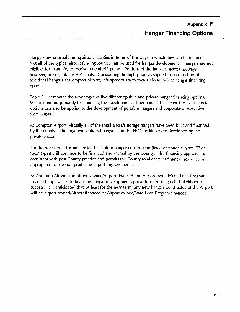
Appendix F
Hangar Financing Options
Hangars are unusual among airport facilities in terms of the ways in which they can be financed.Not all of the typical airport funding sources can be used for hangar development - hangars are noteligible, for example, to receive federal AlP grants. Portions of the hangars' access taxiways,however, are eligible for AlP grants. Considering the high priority assigned to construction ofadditional hangars at Compton Airport, it is appropriate to take a closer look at hangar financingoptions.
Table F-1 compares the advantages of five different' public and private hangar financing options.While intended primarily for financing the development of permanent T-hangars, the five financingoptions can also be applied to the development of portable hangars and corporate or executivestyle hangars.
At Compton Airport, virtually all of the small aircraft storage hangars have been built and financedby the county. The large conventional hangars and the FBO facilities were developed by theprivate sector.
For the near term, it is anticipated that future hangar construction (fixed or portable types liT' or"box" types) will continue to be financed and owned by the County. This financing approach isconsistent with past County practice and permits the County to allocate its financial resources asappropriate to revenue-producing airport improvements.
At Compton Airport, the Airport-owned/Airport-financed and Airport-owned/State Loan Program-financed approaches to financing hangar development appear to offer the greatest likelihood ofsuccess. It is anticipated that, at least for the near term, any new hangars constructed at the Airportwill be airport-owned/Airport-financed or Airport-owned/State Loan Program-financed.
F - 1
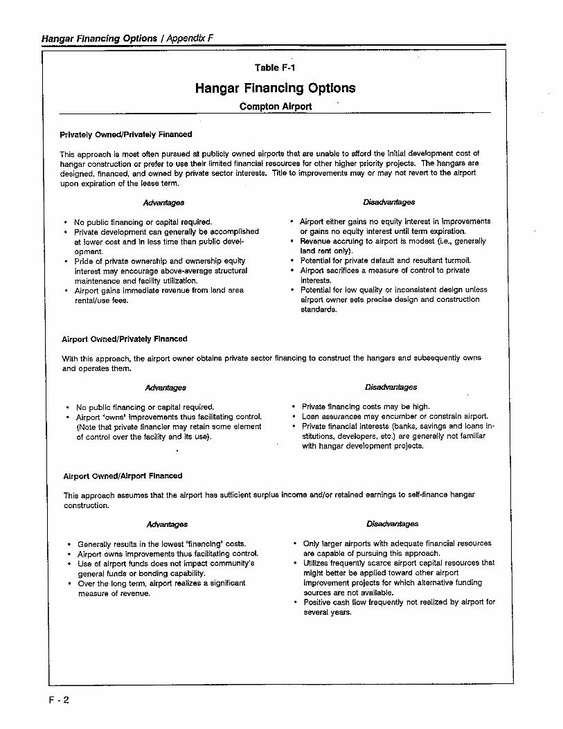
Hangar Financing Options I Appendix F
Table F-1
Hangar Financing OptionsCompton Airport
Privately Owned/Privately Financed
This approach is most often pursued at publicly owned airports that are unable to afford the initial development cost ofhangar construction or prefer to use their limited financial resources for other higher priority projects. The hangars aredesigned, financed, and owned by private sector interests. Title to improvements mayor may not revert to the airportupon expiration of the lease term.
Advges
. No public financing or capital required.
. Private development can generally be accomplished
at lower cost and in less time than public devel-opment.
. Pride of private ownership and ownership equit
interest may encourage above-average structuralmaintenance and facilit utilization.
. Airport gains immediate revenue from land area
rental/use fees.
Airport Owned/Privately Financed
Disadvges
· Airport either gains no equity interest in improvementsor gains no equit interest until term expiration.
. Revenue accruing to airport is modest (i.e., generallyland rent only).
. Potential for private default and resultant turmoiL.
. Airport sacrifices a measure of control to private
interests.. Potential for low quality or inconsistent design unless
airport owner sets precise design and constructionstandards.
With this approach, the airport owner obtains private sector financing to construct the hangars and subsequently ownsand operates them.
Advges
. No public financing or capital required.
. Airport "owns" improvements thus facilitating control.(Note that private financier may retain some elementof control over the facilit and its use).
Airport Owned/Airport Financed
Disadvges
. Private financing costs may be high.
. Loan assurances may encumber or constrain airport.
. Private financial interests (banks, savings and loans in-
stitutions, developers, etc.) are generally not familarwith hangar development projects.
This approach assumes that the airport has suficient surplus income and/or retained earnings to self-finance hangarconstruction.
Adves. Generally results in the lowest "financing" costs.
. Airport owns improvements thus facilitating control.· Use of airport funds does not impact community's
general funds or bonding capabilty.. Over the long term, airport realizes a significant
measure of revenue.
Disadvges
. Only larger airports with adequate financial resources
are capable of pursuing this approach.. Utilzes frequently scarce airport capital resources that
might better be applied toward other airportimprovement projects for which alternative fundingsources are not available.
. Positive cash flow frequently not realized by airport for
several years.
F - 2
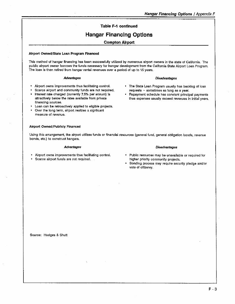
Hangar Financing Options I Appendix F
Table F-1 continued
Hangar Financing OptionsCompton Airport
Airport Owned/State Loan Program Financed
This method of hangar financing has been successfully utilzed by numerous airport owners in the state of California. Thepublic airport owner borrows the funds necessary for hangar development from the California State Airport Loan Program.The loan is then retired from hangar rental revenues over a period of up to 15 years.
Advges Disadvtages
. Airport owns improvements thus faciltating control.
. Scarce airport and communit funds are not required.
. Interest rate charged (currently 7.5% per annum) is
attractively below the rates available from privatefinancing sources.
. Loan can be retroactively applied to eligible projects.
. Over the long term, airport realizes a signficantmeasure of revenue.
. The State Loan Program usually has backlog of loanrequests - sometimes as long as a year.
. Repayment schedule has constant principal paymentsthus expenses usually exceed revenues in initial years.
Airport Owned/Publicly Financed
Using this arrangement, the airport utilzes funds or financial resources (general fund, general obligation bonds, revenuebonds, etc.) to construct hangars.
Advges Disadvges
. Airport owns improvements thus facilitating control.
. Scarce airport funds are not required.. Public resources may be unavailable or required for
higher priority community projects.. Bonding process may require security pledge and/or
vote of citizenry.
Source: Hodges & Shutt
F - 3
Appendix G
References
California, State of. Department of Transportation. Division of Aeronautics. 1989. Public UseAirport Inventory Data - Compton Airport.
. Department of Transportation. Division of Aeronautics. 1989. The CaliforniaAviation System Plan.
Los Angeles, County of. Aviation Division. 1963. Compton Airport Site Study.
Northrup Corporation. 1972. Los Angeles County Airports Noise Study.
Southern California Association of Governments. 1987. General Aviation System Study Phase 1/.
United States, Department of Transportation, Federal Aviation Administration. 1989. FM StatisticalHandbook of Aviation.
1989. General Aviation Activity and Avionics Survey.
1989. Airport Design - Advisory Circular 150/5300-13.
1987. National Plan of Integrated Airport Systems.
1990. FM Aviation Forecasts.
1987. FM Terminal Area Forecasts.
Wilsey, Ham & Blair. 1963. Compton General Plan - Preliminary Report.
G - 1
Appendix H
Glossary
ABOVE GROUND LEVEL (AGL): An elevation datum given in feet above ground leveL.
AIRPORT TRAFFIC CONTROL TOWER (ATCT): A terminal facility that uses air/ground com-munications, visual signaling, and other devices to provide A TC services to aircraft operating in thevicinity of an airport or on the movement area. (AIM)
AIRCRAFT ACCIDENT: An occurrence associated with the operation of an aircraft which takesplace between the time any person boards the aircraft with the intention of flight until such time asall such persons have disembarked, and in which any person suffers death or serious injury as aresult of being in or upon the aircraft or by direct contact with the aircraft or anything attchedthereto, or in which the aircraft receives substantial damage. (NTSB)
AIRCRAFT OPERATION: The airborne movement of aircraft in controlled or noncontrolled airportterminal areas and about given en route fixes or at other points where counts can be made. Thereare two types of operations - local and itinerant. An operation is counted for each landing andeach departure, such that a touch-and-go flight is counted as two operations. (FAA Stats)
AIRCRAFT PARKING LINE LIMIT (APL): A line established by the airport authorities beyond whichno part of a parked aircraft should protrude. (Airport Design AC)
AIRPORT: An area of land or water that is used or intended to be used for the landing and takingoff of aircraft, and includes its buildings and facilities, if any. (FAR 1)
AIRPORT ELEVATION: The highest point of an airport's usable runways, measured in feet abovemean sea leveL. (AIM)
AIRPORT lAYOUT PlAN (ALP): A scale drawing of existing and proposed airport facilities, theirlocation on the airport, and the pertinent clearance and dimensional information required todemonstrate conformance with applicable standards.
AIRPORT REFERENCE CODE (ARC): A coding system used to relate airport design criteria to theoperational and physical characteristics of the airplanes intended to operate at the airport. (AirportDesign AC)
AIRPORT lAND USE COMMISSION (ALUC): A commission established under provisions of Cali-fornia Public Utilities Code, Sections 12670 et seq., in each county within which a public-useairport is located for the purpose of ensuring the orderly expansion of airports and the adoption ofland use measures that minimize the public's exposure to excessive airport noise and safety hazards.(Chapter 4, Article 3.5 of State Aeronautics Act)
AMBIENT NOISE LEVEL: Background noise levee, the normal Of existing level of environmentalnoise at a given location.
H - 1
Glossary I Appendix H
APPROACH LIGHT SYSTEM (ALS): An airport lighting system which provides visual guidanceenabling a pilot to align the aircraft with the extended runway centerline during a final approach tolanding. Among the specific types of systems are:
· LOIN - Sequenced Flashing Lead-in Lights.· OOALS - Omnidirectional Approach Light System, a combination of LOIN and REILS.· SSALR - Simplified Short Approach Light System with Sequenced Flashing Lights. (AIM)
APPROACH SPEED: The recommended speed contained in aircraft manuals used by pilots whenmaking an approach to landing. This speed wil vary for different segments of an approach as wellas for aircraft weight and configuration. (AIM)
AVIGATION EASEMENT: A type of easement that includes the following rights or restrictions: (1)the right of overflight above the property at any altitude above a surface specified in the easement.(2) A right to subject the property to noise, vibrations, fumes, dust, emissions associated with airportactivities. (3) Prohibits the erection or growth of any object, tree or structure that would penetratethe defined airspace. (4) A right of entry to the property, with proper notice to the owner for thepurpose of removing, marking, or lighting any structure or other object that may constitute a hazardor obstruction. (5) Prohibits certain land use characteristics that may create flight hazards, including
electrical interference, glare, misleading light sources, smoke, steam, dust or other visual impair-ments and uses which may attract large flocks of birds.
BASED AIRCRAFT: Aircraft stationed at an airport on a long-term basis.
CEILING: Height above the earth's surface to the lowest layer of clouds or obscuring phenomena.(AIM)
CIRCLING APPROACH/CIRCLE-TO-LAND MANEUVER: A maneuver initiated by the pilot to alignthe aircraft with a runway for landing when a straight-in landing from an instrument approach is notpossible or not desirable. (AIM)
COMMERCIAL OPERATOR: A person who, for compensation or hire, engages in the carriage byaircraft in air commerce of persons or property, other than as an air carrier. (FAR 1)
COMMUNITY NOISE EQUIVALENT LEVEL (CNEL): The noise measure adopted by the State ofCalifornia for evaluating airport noise. It represents the composite noise levels of aircraft operationsduring an average annual 24-hour day. CNEL is measured in A-weighted decibels (dBA) andevening and nighttime operations are weighted to reflect a community's greater sensitivity to noiseduring these hours and to account for quieter ambient levels.
COMMUTER AIR CARRIER: An air taxi operator which performs at least five round trips per weekbetween two or more points and publishes flght schedules which specify the times, days of theweek and places between which such flights are performed. (FAA Census)
CONTROL ZONE: Controlled airspace surrounding one or more airports, normally a circular area.Having a radius of five statute miles plus extensions to include instrument arrival and departure
H - 2
Glossary I Appendix H
paths. Most control zones surround airports with air traffic control towers and are in effect only forthe hours the tower is operationaL.
CONTROLLED AIRSPACE: Any of several types of airspace within which some or all aircraft maybe subject to air traffic control. (FAR 1)
DAY-NIGHT AVERAGE SOUND LEVEL (Ldn): The noise descriptor adopted by the U.S. Environ-mental Protection Agency for measurement of environmental noise. It represents the averagedaytime noise level during a 24-hour day, measured in decibels and adjusted to account for thelower tolerance of people to noise during nighttime periods.
DECIBELS, A-WEIGHTED (dBA): A measure of sound level, adjusted to account for the perceptionrange of the human ear.
DEED NOTICE: A deed notice is a formal statement which is added to the legal description of thedeed for a property and on any subdivision map which states that the property is subject to aircraftoverflights. Oeed notices are used as a form of buyer notification as a means of ensuring that thosewho are particularly sensitive to aircraft overflights can avoid moving to the affected areas. (Refer tooverflight easement.)
DISPLACED THRESHOLD: A landing threshold that is located at a point on the runway other thanthe designated beginning of the runway. (See Threshold) (AIM)
FEDERAL AVIATION REGULATIONS (FAR): Regulations issued by the FAA to regulate air com-merce; issued as separate "Parts", e.g., Part 77.
FAR PART 77: The part of the Federal Aviation Regulations which çleals with objects affectingnavigable airspace.
FAR PART 77 SURFACES: Imaginary surfaces established with relation to each runway of anairport. There are five types of surfaces: (1) primary; (2) approach; (3) transitional; (4) horizontal;and (5) conicaL.
FEDERAL AVIATION ADMINISTRATION (FAA): The United States government agency which isresponsible for insuring the safe and efficient use of the nation's airspace.
FIXED BASE OPERATOR (FBO): A business operating at an airport that provides aircraft services tothe general public, including but not limited to sale of fuel and oil; aircraft sales, rental, main-tenance, and repair; parking and tiedown or storage of aircraft; flight training; air tai/charter opera-tions; and specialty services, such as instrument and avionics maintenance, painting, overhaul, aerialapplication, aerial photography, aerial hoists, or pipeline patrol.
GENERAL AVIATION: That portion of civil aviation which encompasses all facets of aviation exceptair carriers. (FAA Stats)
H - 3
Glossary I Appendix H
GLIDE SLOPE: An electronic signal radiated by a component of an ILS to provide descent path
guidance to approaching aircraft.
HELIPAD: A small, designated area, usually with a prepared surface, on a heliport, airport, land-ing/takeoff area, apron/ramp, or movement area used for . takeoff, landing, or parking of helicopters.
(AIM)
INSTRUMENT APPROACH PROCEDURE: A series of predetermined maneuvers for the orderlytransfer of an aircraft under instrument flight conditions from the beginning of the initial approachto a landing or to a point from which a landing may be made visually. It is prescribed and ap-proved for a specific airport by competent authority. Refer to non precision and precision approach
procedures. (AIM)
INSTRUMENT FLIGHT RULES (IFR): Rules governing the procedures for conducting instrumentflight. Generally, IFR applies when meteorological conditions with a ceiling below 1,000 feet andvisibility less than 3 miles prevaiL. (AIM)
INSTRUMENT LANDING SYSTEM (ILS): A precision instrument approach system which normallyconsists of the following electronic components and visual aids: (1) Localizer; (2) Glide Slope; (3)Outer Marker; (4) Middle Marker; (5) Approach Lights. (AIM)
INSTRUMENT OPERATION: An aircraft operation in accordance with an IFR flight plan or anoperation where IFR separation between aircraft is provided by a terminal control facility. (FAAAT A)
INSTRUMENT RUNWAY: A runway equipped with electronic and visual navigation aids for whicha precision or non precision approach procedure having straight-in landing minimums has beenapproved. (AIM)
ITINERANT OPERATION: An arrival or departure performed by an aircraft from or to a pointbeyond the local airport area.
LARGE AIRCRAFT: An aircraft of more than 12,500 pounds maximum certificated takeoff weight.
(FAR 1)
LOCALIZER (LOC): The component of an ILS which provides course guidance to the runway.
(AIM)
LOCALIZER TYPE DIRECTIONAL AID (LDA): A NAVAl 0 used for non precision instrumentapproaches with utility and accuracy comparable to a localizer but which is no a part of a completeILS and is not aligned with the runway. (AIM)
LOCAL OPERATION: An arrival or departure performed by an aircraft: (1) operating in the trafficpattern, (2) known to be departing or arriving from flight in local practice areas, or (3) executingpractice instrument approaches at the airport. (FAA ATA)
H - 4
Glossary I Appendix H
MEAN SEA LEVEL (MSL): An elevation datum given in feet above mean sea leveL.
MICROWAVE LANDING SYSTEM (MLS): A precision instrument approach system providing afunction similar to an ILS, but operating in the microwave spectrum. It normally consists of threecomponents: azimuth station, elevation station, and precision distance measuring equipment.
MINIMUM DESCENT ALTITUDE (MDA): The lowest altitude, expressed in feet above mean sealevel, to which descent is authorized on final approach or during circle-to-Iand maneuvering inexecution of a standard instrument approach procedure where no electronic glide slope is provided.
(FAR 1)
MISSED APPROACH: A maneuver conducted by a pilot when an instrument approach cannot becompleted to a landing. (AIM)
NAVIGATIONAL AID/NAVAID: Any visual or electronic device airborne or on the surface whichprovides point-to-point guidance information or position data to aircraft in flight. (AIM)
NOISE CONTOURS: Lines drawn about a noise source indicating constant energy levels of noiseexposure. CNEL and Ldn are the measures used to describe community exposure to noise.
NON PRECISION APPROACH PROCEDURE: A standard instrument approach procedure in whichno electronic glide slope is provided. (FAR 1)
NONPRECISION INSTRUMENT RUNWAY: A runway with an instrument approach procedureutilizing air navigation facilities, with only horizontal guidance, or area-type navigation equipmentfor which a straight-in non precision instrument approach procedure has been approved or planned,and no precision approach facility or procedure is planned. (Airport Design AC)
OBJECT FREE AREA (OFA): A two-dimensional ground area surrounding runways, taiways, andtaxi lanes which is clear of objects except for objects whose location is fixed by function. (AirportOesign AC)
OBSTRUCTION: Any object of natural growth, terrain, or permanent or temporary construction oralteration, including equipment or materials used therein the height of which exceeds the obstruc-tion standards of subpart C of FAR Part 77 "Objects Affecting Navigable Airspace".
OBSTACLE FREE ZONE (OFZ): The airspace defined by the runway OFZ and, as appropriate, theinner-approach OFZ and the inner-transitional OFZ, which is clear of object penetrations other thanfrangible NAVAIOs.
OBSTRUCTION: An object, including a mobile object, which penetrates an imaginary surfacedescribed in FAR Part 77.
OUTER MARKER: A marker beacon at or near the glide slope intercept position of an ILS ap-proach. (AIM)
H - 5
Glossary I Appendix H
OVERFLIGHT EASEMENT: An easement which describes the right to overfly the property above aspecified surface and includes the right to subject the propert to noise, vibrations, fumes andemissions. An overflight easement is used primarily as a form of buyer notification.
OVERFLIGHT ZONE: The area(s) where aircraft are maneuvering to enter or leave the trafficpattern, typically defined by the FAR Part 77 horizontal surface.
OVERLAY ZONING: Establishes development standards in areas of special concern over an above. the standards applicable to basic underlying zoning district.
PLANNING BOUNDARY: The area designated by the ALUC surrounding each airport pursuant toSection 21675 (c) of the Public Utilities Code in which the ALUC plan applies.
PRECISION APPROACH PATH INDICATOR (PAPI): An airport landing aid similar to a VASI, butwhich has light units installed in a single row rather than two rows.
PRECISION APPROACH PROCEDURE: A standard instrument approach procedure in which anelectronic glide slope is provided. (FAR 1)
PRECISION INSTRUMENT RUNWAY: A runway with an instrument approach procedure utilizingan instrument landing system (lLS), microwave landing system (MLS), or precision approach radar
(PAR). (Airport Oesign AC)
PUBLIC USE AIRPORT: Publicly or privately owned airport that offers the use of its facilities to thepublic without prior notice or special invitation or clearance, and that has been issued a CaliforniaAirport Permit by the Oivision of Aeronautics of the California Oepartment of Transportation. Forpurposes of the ALUC plan, the State Division of Aeronautics has interpreted "public use" to includespecial-use airport in which commercial operators offer service to the public.
REFERRAL AREA: The area around an airport defined by the planning boundary adopted by theALUC within which certain land use proposals are to be referred to the ALUC for review.
RUNWAY EDGE LIGHTS: Lights used to define the lateral limits of a runway. Specific typesinclude:
· HIRL - High-Intensity Runway Lights.
· MIRL - Medium-Intensity Runway Lights.
RUNWAY END IDENTIFIER LIGHTS (RElL): Two synchronized flashing lights, one on each side ofthe runway threshold, which provide a pilot with a rapid and positive visual identification of theapproach end of a particular runway. (AIM)
RUNWAY PROTECTION ZONE (RPZ): An area (formerly the clear zone) used to enhance thesafety of aircraft operations. It is at ground level beyond the runway end. (Airport Oesign Aq
H - 6
~/ossary I Appendix H
RUNWAY SAFETY AREA (RSA): A defined surface surrounding the runway prepared or suitable forreducing the risk of damage to airplanes in the event of an undershoot, overshoot, or excursionfrom the runway. (Airport Oesign Aq
SAFETY ZONE(S): For the purposes of this Plan, a safety zone is an area near an airport in whichland use restrictions are established to protect the safety of the public from potential aircraftaccidents.
SINGLE-EVENT NOISE: As used in this report, it refers to the noise from an individual aircraftoperation or overflight.
SINGLE EVENT NOISE EXPOSURE LEVEL (SENEL) OR (SEL): The A-weighted sound level of asingle noise event, such as an aircraft overflight, measured over the time interval for which thesound exceeds a threshold level and normalized to a reference duration of one second. SENEL andSEL values are identical: SENEL is used in California, SEL is adopted by the EPA and FAA.
The SENEL or SEL expresses the level of a continuous one-second signal that contains the sameamount of energy as the entire noise event. This value is not equal to the maximum A-leveloccurring during the noise event. Aircraft noise events last more than one second. SENEUSELvalues will be higher than the maximum A-level for the same events.
SMALL AIRCRAFT: An aircraft of 12,500 pounds or less maximum certificated takeoff weight.
(FAR 1)
STANDARD INSTRUMENT DEPARTURE (SID): A preplanned instrument flight rules (lFR) air trafficcontrol departure procedure printed for pilot use in graphic and/or textual form. SIO's providetransition from the terminal to the appropriate en route structure. (AIM)
STANDARD TERMINAL ARRIVAL ROUTE (STAR): A preplanned instrument flight rule (lFR) airtraffc control arrival route published for pilot use in graphic and/or textual form. STARs providetransition from the en route structure to an outer fix or an instrument approach fix/arrival waypointin the terminal area. (AIM)
STOPWAY: An area beyond the takeoff runway, no less wide than the runway and centered uponthe extended centerline of the runway, able to support the airplane during an aborted takeoff,without causing structural damage to the airplane, and designated by the airport authorities for usein decelerating the airplane during an aborted takeoff. (FAR 1)
STRAIGHT-IN INSTRUMENT APPROACH: An instrument approach wherein final approach isbegun without first having executed a procedure turn; it is not necessarily completed with astraight-in landing or made to straight-in landing weather minimums. (AIM)
TAXI LANE: The portion of the aircraft parking area used for access between taiways, aircraftparking positions, hangars, storage facilities, etc. (Airport Oesign Aq
H -7
Glossary .1 Appendix H
TAXIWAY: A defined path, from one part of an airport to another, selected or prepared for thetaiing of aircraft. (Airport Oesign Aq
TERMINAL INSTRUMENT PROCEDURES (TERPS): Procedures for instrument approach anddeparture of aircraft to and from civil and military airports. There are four types of terminalinstrument procedures: precision approach, non precision approach, circling, and departure.
TERMINAL RADAR SERVICE AREA (TRSA): Airspace surrounding designated airport wherein ATCprovides radar vectoring, sequencing, and separation on a full-time basis for alllFR and participatingVFR aircraft. (AIM)
THRESHOLD: The beginning of that portion of the runway usable for landing. (AIM) (Also seeOisplaced Threshold)
TOUCH-AND-GO: A practice maneuver consisting of a landing and a takeoff performed in onecontinuous movement. A touch-and-go is defined as two operations.
TRAFFIC PATTERN: The traffic flow that is prescribed for aircraft landing at, taxiing on, or takingoff from an airport. The components of a typical traffic pattern are upwind leg, crosswind leg,downwind leg, base leg, and final approach. (AIM)
TRANSIENT AIRCRAFT: Aircraft not based at the airport.
UNICOM (Aeronautical Advisory Station): A nongovernment air/ground radio communicationfacility which may provide airport information at certain airports. (AIM)
UTILITY AIRPORT: An airport designed, constructed, and maintained to serve airplanes havingapproach speeds less than 121 knots. (Airport Oesign Aq
VISUAL APPROACH: An approach where the pilot must use visual reference to the runway forlanding under VFR conditions.
VISUAL APPROACH SLOPE INDICATOR (VASt): An airport landing aid which provides a pilotwith visual descent (approach slope) guidance while on approach to landing. Also see PAP\.
VISUAL FLIGHT RULES (VFR): Rules that govern the procedures for conducting flight under visualconditions. VFR applies when meteorological conditions are equal to or greater than the specifiedminimum - generally, a 1 ,OOO-foot ceiling and 3-mile visibility.
VISUAL GLIDE SLOPE INDICATOR (VGSI): A generic term for the group of airport visual landing
aids which includes Visual Approach Slope Indicators (VASI), Precision Approach Path Indicators
(PAPI), and Pulsed Light Approach Slope Indicators (PLASI). When FAA funding pays for thisequipment, whichever type received the lowest bid price will be installed unless the airport ownerwishes to pay the difference for a more expensive unit.
H - 8
Glossary 1 Appendix H
VISUAL RUNWAY: A runway intended solely for the operation of aircraft using visual approachprocedures, with no straight-in instrument approach procedure and no instrument designationindicated on an FAA-approved airport layout plan. (Airport Oesign AC)
WIND SHEER: A condition typified by rapid changes in wind velocity and duration with altitude.
H - 9