Embed Size (px)
Citation preview
DOI: 10.1002/srin.201000021 steel research int. 81 (2010) No. 5
Computational Analysis of Precipitation d
uring Continuous Casting of MicroalloyedSteelM. Pudar1)*, S. Zamberger2), K. Spiradek-Hahn3), R. Radis1,4), and E. Kozeschnik4)
1) Institute for Material Science and Welding, Graz University of Technology, Kopernikusgasse 24/I, 8010 Graz, Austria now at: Magna Steyr
Fahrzeugtechnik, Liebenauer Hauptstraße 317, 8042 Graz, Austria, [email protected]) voestalpine Stahl Donawitz GmbH & Co KG, Kerpelystrasse 199, 8700 Leoben, Austria3) AIT – Austrian Institute of Technology GmbH, Advanced Materials & Aerospace Technology/Alloy Development Group, 2444 Seibersdorf,
Austria4) Christian Doppler Laboratory for Early Stages of Precipitation, Institute of Materials Science and Technology, Vienna University of
Technology, Favoritenstraße 9-11/E308, 1040 Vienna, Austria
* Corresponding author
In this paper, the kinetics of TiN, V(C,N)) and AlN precipitation in microalloyed steel during continuous casting is investigated experimentally and
theoretically. The precipitate phase fraction, mean radius, number density and composition are simulated with the thermo-kinetic software
MatCalc and compared with experimental results obtained from transmission electron microscopy analysis. A new methodology for modelling
precipitation in cast steel is proposed, which consists of two parts: First, a Scheil – Gulliver simulation, which is carried out to obtain information
on the amount of microsegregation during solidification. Then, based on this information, two precipitation kinetics simulations are performed:
One with the chemical composition representative for the solute-poor core of the secondary dendrite arms, the other with the composition of the
residual liquid at a fraction of 5%, corresponding to the segregated solute-rich interdendritic regions. The results of the computer simulations
using the new methodology are in good agreement with experimental observation.
Keywords: precipitation, microalloyed steel, micro segregation, continuous casting
Submitted on 7 February 2010, accepted on 12 February 2010
Introduction
The (numerical) prediction and control of precipitationin microalloyed steel is crucial for maintenance of ductilityand avoidance of surface crack formation in bending andstraightening operations of the bloom during continuouscasting.
The effects of microalloying elements on the hot ductilityof steel have been intensively investigated [1–4]. In moststudies, interpretation of results is based on the nominal steelcomposition. In cast materials, however, local fluctuations incomposition due to micro and macro-segregation lead tolocal variations in driving forces, solubility temperatures,precipitation start times and temperatures. These have to betaken into account when attempting realistic simulations ofthe precipitation state in the primary solidification micro-structure of cast steels.
Microsegregation in complex, multi-component alloys isoften studied in the framework of the Scheil-Gulliver model[5, 6]. In this model, diffusion in the liquid is assumed to beinfinitely fast, whereas diffusion in the solid is assumed to benegligibly slow. With the assumption of local equilibrium atthe liquid/solid interface, the rejection of solute atoms intothe liquid can be calculated with minimum computationaleffort. Several models for prediction of microsegregationduring casting are reported in the literature, e.g. [7–10].
372 � 2010 Wiley-VCH Verlag GmbH & Co. KGaA, Wein
In the case of alloys containing substitutional andinterstitial elements, fast diffusion of interstitials in thesolid must be taken into account by assuming that the fastelements are capable of diffusing back from the liquid intothe solid [9, 10]. This process is known as back-diffusion andit is implemented, e.g., in the software MatCalc [11–14].
In the present analysis, the Scheil-Gulliver simulationmodule of this software is used to study microsegregation ofelements during the continuous casting process. The resultsof this simulation are then used in a second step to predictthe precipitation kinetics of carbides and nitrides in thesegregated and non-segregated regions of the primarysolidification microstructure. Successful application of thecorresponding precipitation kinetics model have beenreported previously [15, 16].
Using a special microsegregation model, Kunze et al. [17–19] have investigated the range of Ti and N supersaturation,which is necessary to form TiN precipitates during and afterferritic and austenitic solidification. Their analysis wasfocussed on the mean particle radius of the precipitates inthe austenite region. In the present work, we introduce amore general computational concept for the prediction of theprecipitation kinetics in multi-component alloys, where thelocal micro segregation state is fully taken into account inprecipitation kinetics simulations. The methodology of thisapproach is described in detail, subsequently. The model is
heim www.steelresearch-journal.com
Materials Technology steel research int. 81 (2010) No. 5
Table 1. Nominal composition of the investigated steel [wt%].
C Mn Al Ti V Nb N
0.21 1.553 0.0249 0.0028 0.137 0.0008 0.0135
then applied to the prediction of the precipitate evolutionduring continuous casting of a V-containing microalloyedsteel and compared to an experimental analysis based ontransmission electron microscopy.
Experimental
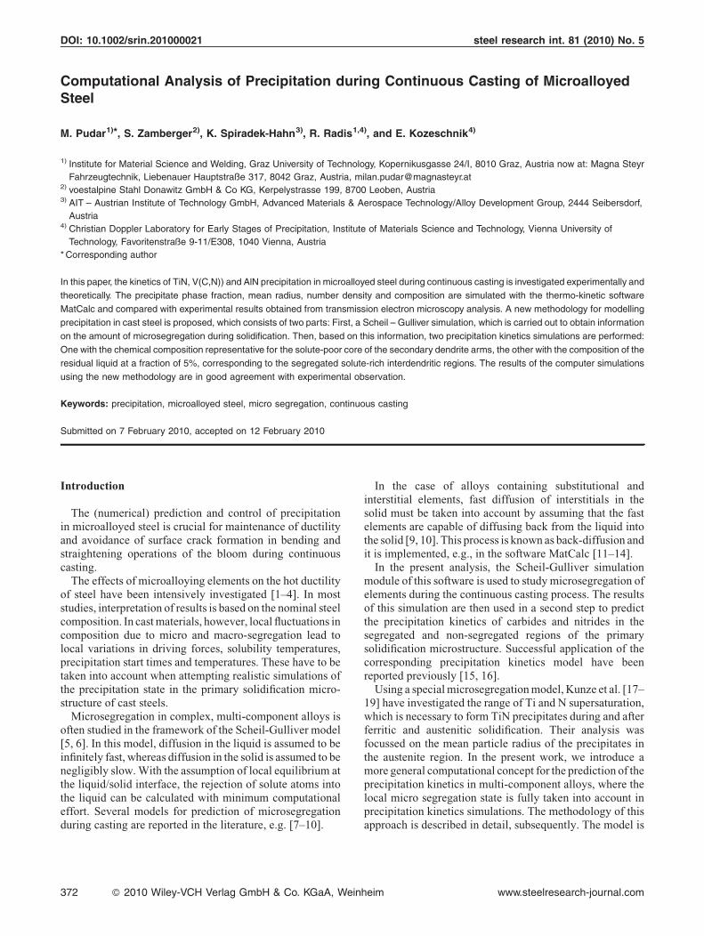
The present work is carried out on industrial continuouslycast microalloyed steel, with the dimension of Ø 230 mm.The microstructural investigations are performed on sam-ples taken approximately 10 mm underneath the bloomsurface. Figure 1 shows the V concentration mapping frommicroprobe analysis taken at the bloom centre and at aregion close to the bloom surface. The figure clearly showsthe extent of microsegregation in the present steel afterthe continuous casting process. Table 1 summarizes thechemical composition of the investigated steel.
Model
While a multi-component alloy solidifies, microsegrega-tion of elements leads to locally changing chemicalcomposition. Commonly, the cores of the secondarydendrite arms become depleted from solute atoms, whereasthe inter-dendritic regions show more or less heavy enrich-ment of these elements. Consequently, the precipitationprocess during cooling strongly depends on the location
Figure 1. Vanadium concentration (wt.-%) mapping of continuously cast s
near bloom surface; right – bloom centre.
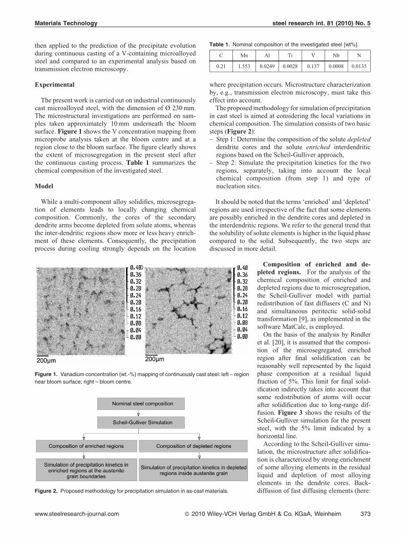
Figure 2. Proposed methodology for precipitation simulation in as-cast m
www.steelresearch-journal.com � 2010 W
where precipitation occurs. Microstructure characterizationby, e.g., transmission electron microscopy, must take thiseffect into account.
The proposed methodology for simulation of precipitationin cast steel is aimed at considering the local variations inchemical composition. The simulation consists of two basicsteps (Figure 2):
– Ste
ate
il
tep 1: Determine the composition of the solute depleteddendrite cores and the solute enriched interdendriticregions based on the Scheil-Gulliver approach,
– S
tep 2: Simulate the precipitation kinetics for the tworegions, separately, taking into account the localchemical composition (from step 1) and type ofnucleation sites.It should be noted that the terms ‘enriched’ and ‘depleted’regions are used irrespective of the fact that some elementsare possibly enriched in the dendrite cores and depleted inthe interdendritic regions. We refer to the general trend thatthe solubility of solute elements is higher in the liquid phasecompared to the solid. Subsequently, the two steps arediscussed in more detail.
el: left – region
rials.
ey-VCH Verlag
Composition of enriched and de-pleted regions. For the analysis of thechemical composition of enriched anddepleted regions due to microsegregation,the Scheil-Gulliver model with partialredistribution of fast diffusers (C and N)and simultaneous peritectic solid-solidtransformation [9], as implemented in thesoftware MatCalc, is employed.
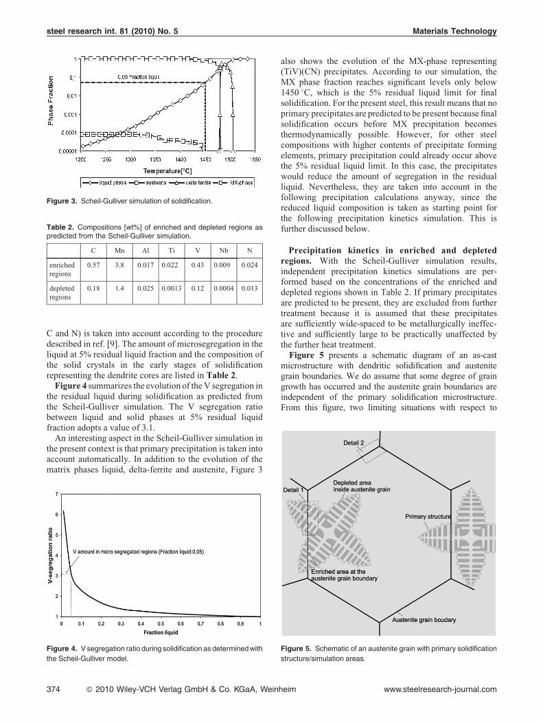
On the basis of the analysis by Rindleret al. [20], it is assumed that the composi-tion of the microsegregated, enrichedregion after final solidification can bereasonably well represented by the liquidphase composition at a residual liquidfraction of 5%. This limit for final solid-ification indirectly takes into account thatsome redistribution of atoms will occurafter solidification due to long-range dif-fusion. Figure 3 shows the results of theScheil-Gulliver simulation for the presentsteel, with the 5% limit indicated by ahorizontal line.
According to the Scheil-Gulliver simu-lation, the microstructure after solidifica-tion is characterized by strong enrichmentof some alloying elements in the residualliquid and depletion of most alloyingelements in the dendrite cores. Back-diffusion of fast diffusing elements (here:
GmbH & Co. KGaA, Weinheim 373
steel research int. 81 (2010) No. 5 Materials Technology
Figure 3. Scheil-Gulliver simulation of solidification.
Table 2. Compositions [wt%] of enriched and depleted regions aspredicted from the Scheil-Gulliver simulation.
C Mn Al Ti V Nb N
enrichedregions
0.57 3.8 0.017 0.022 0.43 0.009 0.024
depletedregions
0.18 1.4 0.025 0.0013 0.12 0.0004 0.013
C and N) is taken into account according to the proceduredescribed in ref. [9]. The amount of microsegregation in theliquid at 5% residual liquid fraction and the composition ofthe solid crystals in the early stages of solidificationrepresenting the dendrite cores are listed in Table 2.Figure 4 summarizes the evolution of the V segregation in
the residual liquid during solidification as predicted fromthe Scheil-Gulliver simulation. The V segregation ratiobetween liquid and solid phases at 5% residual liquidfraction adopts a value of 3.1.
An interesting aspect in the Scheil-Gulliver simulation inthe present context is that primary precipitation is taken intoaccount automatically. In addition to the evolution of thematrix phases liquid, delta-ferrite and austenite, Figure 3
Figure 4. V segregation ratio during solidification as determined with
the Scheil-Gulliver model.
374 � 2010 Wiley-VCH Verlag GmbH & Co. KGaA, Wein
also shows the evolution of the MX-phase representing(TiV)(CN) precipitates. According to our simulation, theMX phase fraction reaches significant levels only below1450 8C, which is the 5% residual liquid limit for finalsolidification. For the present steel, this result means that noprimary precipitates are predicted to be present because finalsolidification occurs before MX precipitation becomesthermodynamically possible. However, for other steelcompositions with higher contents of precipitate formingelements, primary precipitation could already occur abovethe 5% residual liquid limit. In this case, the precipitateswould reduce the amount of segregation in the residualliquid. Nevertheless, they are taken into account in thefollowing precipitation calculations anyway, since thereduced liquid composition is taken as starting point forthe following precipitation kinetics simulation. This isfurther discussed below.
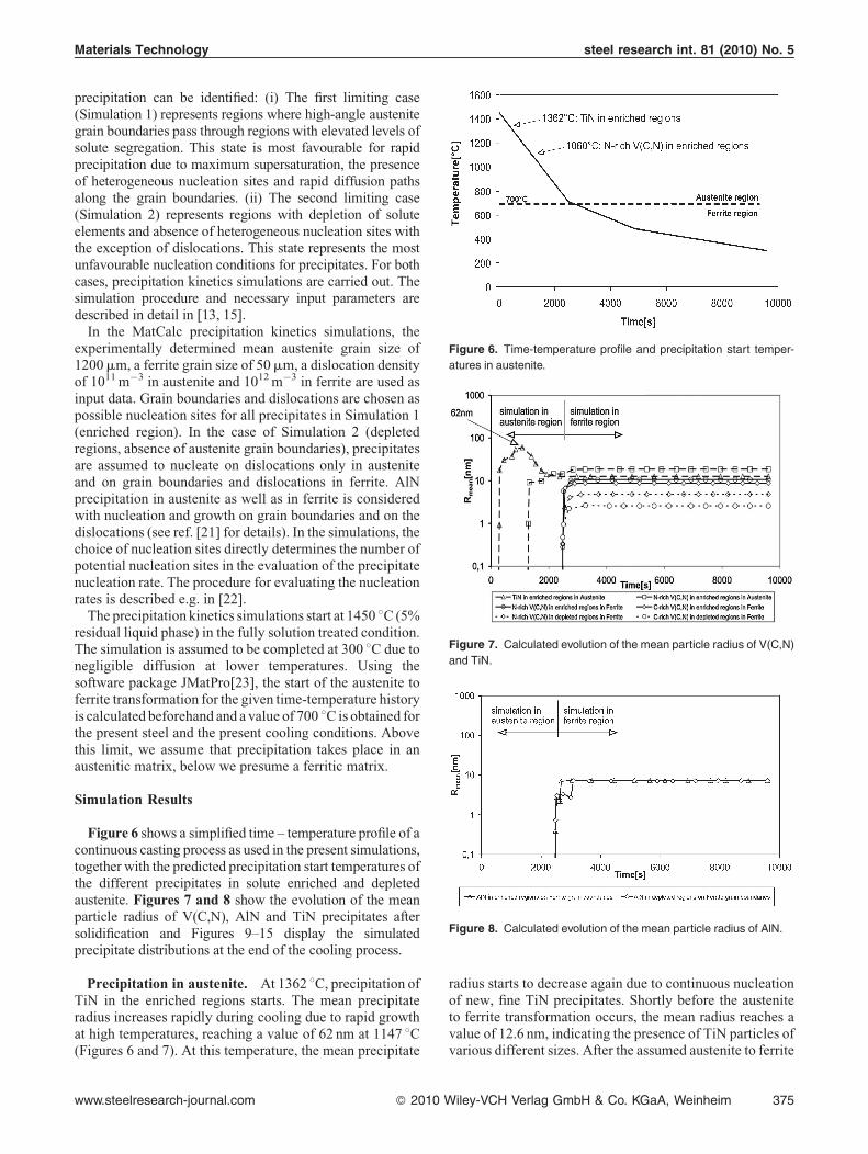
Precipitation kinetics in enriched and depletedregions. With the Scheil-Gulliver simulation results,independent precipitation kinetics simulations are per-formed based on the concentrations of the enriched anddepleted regions shown in Table 2. If primary precipitatesare predicted to be present, they are excluded from furthertreatment because it is assumed that these precipitatesare sufficiently wide-spaced to be metallurgically ineffec-tive and sufficiently large to be practically unaffected bythe further heat treatment.Figure 5 presents a schematic diagram of an as-cast
microstructure with dendritic solidification and austenitegrain boundaries. We do assume that some degree of graingrowth has occurred and the austenite grain boundaries areindependent of the primary solidification microstructure.From this figure, two limiting situations with respect to
Figure 5. Schematic of an austenite grain with primary solidification
structure/simulation areas.
heim www.steelresearch-journal.com
Materials Technology steel research int. 81 (2010) No. 5
Figure 6. Time-temperature profile and precipitation start temper-
atures in austenite.
Figure 7. Calculated evolution of the mean particle radius of V(C,N)
and TiN.
Figure 8. Calculated evolution of the mean particle radius of AlN.
precipitation can be identified: (i) The first limiting case(Simulation 1) represents regions where high-angle austenitegrain boundaries pass through regions with elevated levels ofsolute segregation. This state is most favourable for rapidprecipitation due to maximum supersaturation, the presenceof heterogeneous nucleation sites and rapid diffusion pathsalong the grain boundaries. (ii) The second limiting case(Simulation 2) represents regions with depletion of soluteelements and absence of heterogeneous nucleation sites withthe exception of dislocations. This state represents the mostunfavourable nucleation conditions for precipitates. For bothcases, precipitation kinetics simulations are carried out. Thesimulation procedure and necessary input parameters aredescribed in detail in [13, 15].
In the MatCalc precipitation kinetics simulations, theexperimentally determined mean austenite grain size of1200mm, a ferrite grain size of 50mm, a dislocation densityof 1011 m�3 in austenite and 1012 m�3 in ferrite are used asinput data. Grain boundaries and dislocations are chosen aspossible nucleation sites for all precipitates in Simulation 1(enriched region). In the case of Simulation 2 (depletedregions, absence of austenite grain boundaries), precipitatesare assumed to nucleate on dislocations only in austeniteand on grain boundaries and dislocations in ferrite. AlNprecipitation in austenite as well as in ferrite is consideredwith nucleation and growth on grain boundaries and on thedislocations (see ref. [21] for details). In the simulations, thechoice of nucleation sites directly determines the number ofpotential nucleation sites in the evaluation of the precipitatenucleation rate. The procedure for evaluating the nucleationrates is described e.g. in [22].
The precipitation kinetics simulations start at 1450 8C (5%residual liquid phase) in the fully solution treated condition.The simulation is assumed to be completed at 300 8C due tonegligible diffusion at lower temperatures. Using thesoftware package JMatPro[23], the start of the austenite toferrite transformation for the given time-temperature historyis calculated beforehand and a value of 700 8C is obtained forthe present steel and the present cooling conditions. Abovethis limit, we assume that precipitation takes place in anaustenitic matrix, below we presume a ferritic matrix.
Simulation Results
Figure 6 shows a simplified time – temperature profile of acontinuous casting process as used in the present simulations,together with the predicted precipitation start temperatures ofthe different precipitates in solute enriched and depletedaustenite. Figures 7 and 8 show the evolution of the meanparticle radius of V(C,N), AlN and TiN precipitates aftersolidification and Figures 9–15 display the simulatedprecipitate distributions at the end of the cooling process.
Precipitation in austenite. At 1362 8C, precipitation ofTiN in the enriched regions starts. The mean precipitateradius increases rapidly during cooling due to rapid growthat high temperatures, reaching a value of 62 nm at 1147 8C(Figures 6 and 7). At this temperature, the mean precipitate
www.steelresearch-journal.com � 2010 W
radius starts to decrease again due to continuous nucleationof new, fine TiN precipitates. Shortly before the austeniteto ferrite transformation occurs, the mean radius reaches avalue of 12.6 nm, indicating the presence of TiN particles ofvarious different sizes. After the assumed austenite to ferrite
iley-VCH Verlag GmbH & Co. KGaA, Weinheim 375
steel research int. 81 (2010) No. 5 Materials Technology
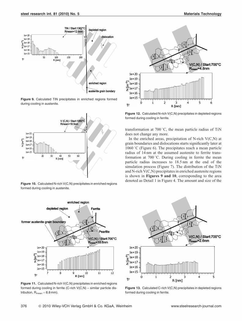
Figure 10. Calculated N-rich V(C,N) precipitates in enriched regions
formed during cooling in austenite.
Figure 11. Calculated N-rich V(C,N) precipitates in enriched regions
formed during cooling in ferrite (C-rich V(C,N) – similar particle dis-
tribution, Rmean¼ 8.8 mm).
Figure 12. Calculated N-rich V(C,N) precipitates in depleted regions
formed during cooling in ferrite.
Figure 9. Calculated TiN precipitates in enriched regions formed
during cooling in austenite.
376 � 2010 Wiley-VCH Verlag GmbH & Co. KGaA, Wein
transformation at 700 8C, the mean particle radius of TiNdoes not change any more.
In the enriched areas, precipitation of N-rich V(C,N) atgrain boundaries and dislocations starts significantly later at1060 8C (Figure 6). The precipitates reach a mean particleradius of 14 nm at the assumed austenite to ferrite trans-formation at 700 8C. During cooling in ferrite the meanparticle radius increases to 18.5 nm at the end of thesimulation process (Figure 7). The distribution of the TiNand N-rich V(C,N) precipitates in enriched austenite regionsis shown in Figures 9 and 10, corresponding to the areadenoted as Detail 1 in Figure 4. The amount and size of the
Figure 13. Calculated C-rich V(C,N) precipitates in depleted regions
formed during cooling in ferrite.
heim www.steelresearch-journal.com
Materials Technology steel research int. 81 (2010) No. 5
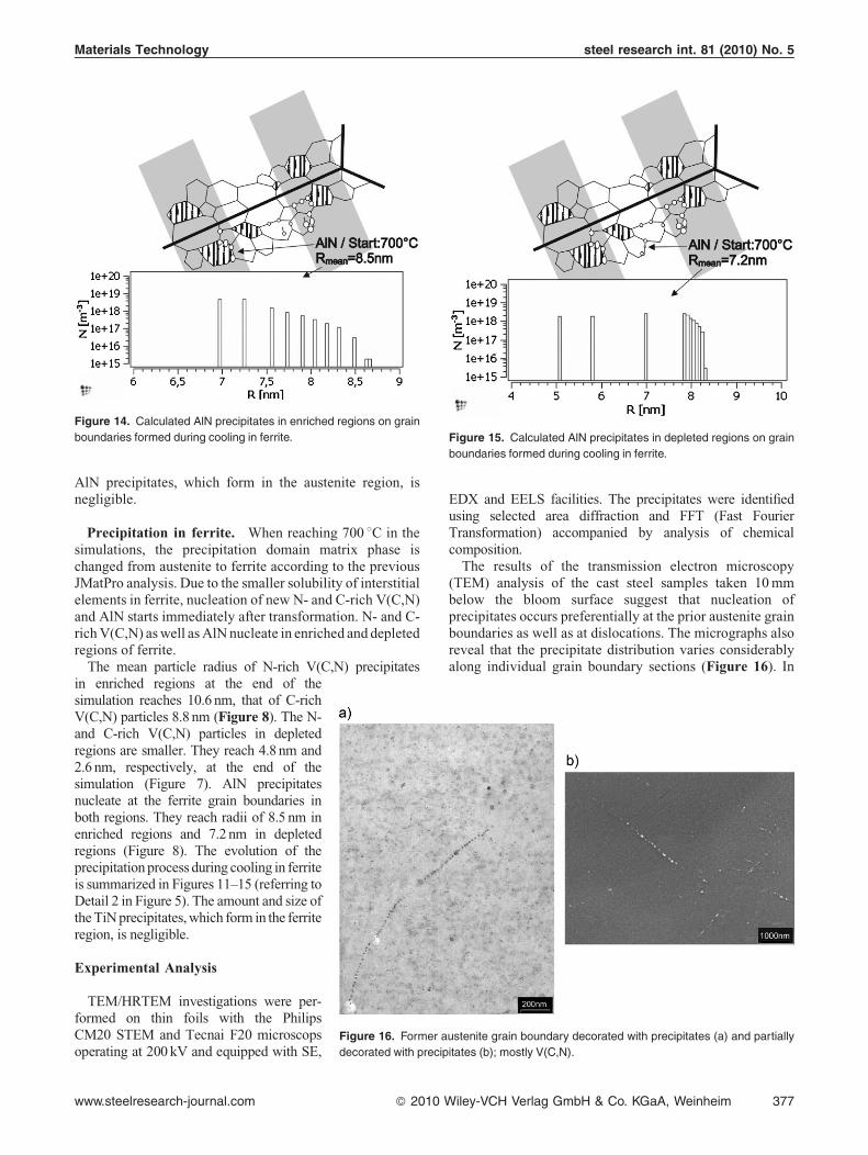
Figure 14. Calculated AlN precipitates in enriched regions on grain
boundaries formed during cooling in ferrite. Figure 15. Calculated AlN precipitates in depleted regions on grain
boundaries formed during cooling in ferrite.
AlN precipitates, which form in the austenite region, isnegligible.
Precipitation in ferrite. When reaching 700 8C in thesimulations, the precipitation domain matrix phase ischanged from austenite to ferrite according to the previousJMatPro analysis. Due to the smaller solubility of interstitialelements in ferrite, nucleation of new N- and C-rich V(C,N)and AlN starts immediately after transformation. N- and C-rich V(C,N) as well as AlN nucleate in enriched and depletedregions of ferrite.
The mean particle radius of N-rich V(C,N) precipitates
Figure 16. Former austenite grain boundary decorated with precipitates (a) and partially
decorated with precipitates (b); mostly V(C,N).
in enriched regions at the end of thesimulation reaches 10.6 nm, that of C-richV(C,N) particles 8.8 nm (Figure 8). The N-and C-rich V(C,N) particles in depletedregions are smaller. They reach 4.8 nm and2.6 nm, respectively, at the end of thesimulation (Figure 7). AlN precipitatesnucleate at the ferrite grain boundaries inboth regions. They reach radii of 8.5 nm inenriched regions and 7.2 nm in depletedregions (Figure 8). The evolution of theprecipitation process during cooling in ferriteis summarized in Figures 11–15 (referring toDetail 2 in Figure 5). The amount and size ofthe TiN precipitates, which form in the ferriteregion, is negligible.
Experimental Analysis
TEM/HRTEM investigations were per-formed on thin foils with the PhilipsCM20 STEM and Tecnai F20 microscopsoperating at 200 kV and equipped with SE,
www.steelresearch-journal.com � 2010 W
EDX and EELS facilities. The precipitates were identifiedusing selected area diffraction and FFT (Fast FourierTransformation) accompanied by analysis of chemicalcomposition.
The results of the transmission electron microscopy(TEM) analysis of the cast steel samples taken 10 mmbelow the bloom surface suggest that nucleation ofprecipitates occurs preferentially at the prior austenite grainboundaries as well as at dislocations. The micrographs alsoreveal that the precipitate distribution varies considerablyalong individual grain boundary sections (Figure 16). In
iley-VCH Verlag GmbH & Co. KGaA, Weinheim 377
steel research int. 81 (2010) No. 5 Materials Technology
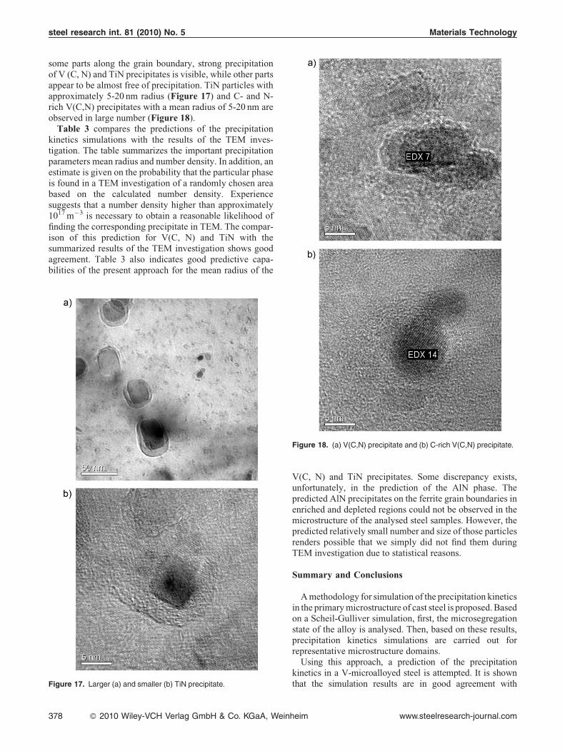
some parts along the grain boundary, strong precipitationof V (C, N) and TiN precipitates is visible, while other partsappear to be almost free of precipitation. TiN particles withapproximately 5-20 nm radius (Figure 17) and C- and N-rich V(C,N) precipitates with a mean radius of 5-20 nm areobserved in large number (Figure 18).Table 3 compares the predictions of the precipitation
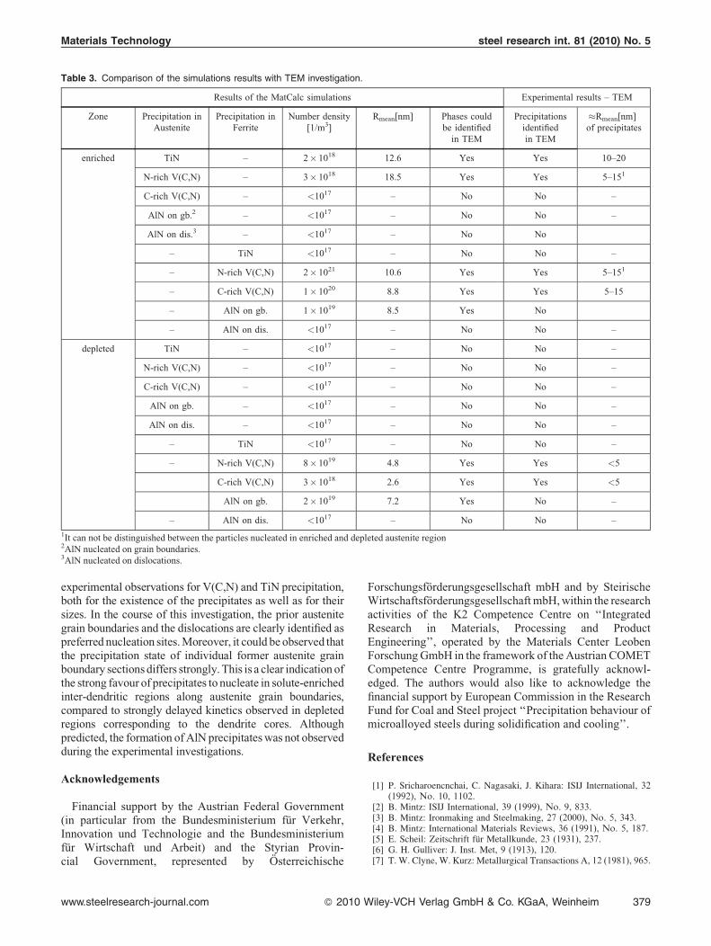
kinetics simulations with the results of the TEM inves-tigation. The table summarizes the important precipitationparameters mean radius and number density. In addition, anestimate is given on the probability that the particular phaseis found in a TEM investigation of a randomly chosen areabased on the calculated number density. Experiencesuggests that a number density higher than approximately1017 m�3 is necessary to obtain a reasonable likelihood offinding the corresponding precipitate in TEM. The compar-ison of this prediction for V(C, N) and TiN with thesummarized results of the TEM investigation shows goodagreement. Table 3 also indicates good predictive capa-bilities of the present approach for the mean radius of the
Figure 17. Larger (a) and smaller (b) TiN precipitate.
Figure 18. (a) V(C,N) precipitate and (b) C-rich V(C,N) precipitate.
378 � 2010 Wiley-VCH Verlag GmbH & Co. KGaA, Wein
V(C, N) and TiN precipitates. Some discrepancy exists,unfortunately, in the prediction of the AlN phase. Thepredicted AlN precipitates on the ferrite grain boundaries inenriched and depleted regions could not be observed in themicrostructure of the analysed steel samples. However, thepredicted relatively small number and size of those particlesrenders possible that we simply did not find them duringTEM investigation due to statistical reasons.
Summary and Conclusions
A methodology for simulation of the precipitation kineticsin the primary microstructure of cast steel is proposed. Basedon a Scheil-Gulliver simulation, first, the microsegregationstate of the alloy is analysed. Then, based on these results,precipitation kinetics simulations are carried out forrepresentative microstructure domains.
Using this approach, a prediction of the precipitationkinetics in a V-microalloyed steel is attempted. It is shownthat the simulation results are in good agreement with
heim www.steelresearch-journal.com
Materials Technology steel research int. 81 (2010) No. 5
Table 3. Comparison of the simulations results with TEM investigation.
Results of the MatCalc simulations Experimental results – TEM
Zone Precipitation inAustenite
Precipitation inFerrite
Number density[1/m3]
Rmean[nm] Phases couldbe identified
in TEM
Precipitationsidentifiedin TEM
�Rmean[nm]of precipitates
enriched TiN – 2� 1018 12.6 Yes Yes 10–20
N-rich V(C,N) – 3� 1018 18.5 Yes Yes 5–151
C-rich V(C,N) – <1017 – No No –
AlN on gb.2 – <1017 – No No –
AlN on dis.3 – <1017 – No No
– TiN <1017 – No No –
– N-rich V(C,N) 2� 1021 10.6 Yes Yes 5–151
– C-rich V(C,N) 1� 1020 8.8 Yes Yes 5–15
– AlN on gb. 1� 1019 8.5 Yes No
– AlN on dis. <1017 – No No –
depleted TiN – <1017 – No No –
N-rich V(C,N) – <1017 – No No –
C-rich V(C,N) – <1017 – No No –
AlN on gb. – <1017 – No No –
AlN on dis. – <1017 – No No –
– TiN <1017 – No No –
– N-rich V(C,N) 8� 1019 4.8 Yes Yes <5
C-rich V(C,N) 3� 1018 2.6 Yes Yes <5
AlN on gb. 2� 1019 7.2 Yes No –
– AlN on dis. <1017 – No No –
1It can not be distinguished between the particles nucleated in enriched and depleted austenite region2AlN nucleated on grain boundaries.3AlN nucleated on dislocations.
experimental observations for V(C,N) and TiN precipitation,both for the existence of the precipitates as well as for theirsizes. In the course of this investigation, the prior austenitegrain boundaries and the dislocations are clearly identified aspreferred nucleation sites. Moreover, it could be observed thatthe precipitation state of individual former austenite grainboundary sections differs strongly. This is a clear indication ofthe strong favour of precipitates to nucleate in solute-enrichedinter-dendritic regions along austenite grain boundaries,compared to strongly delayed kinetics observed in depletedregions corresponding to the dendrite cores. Althoughpredicted, the formation of AlN precipitates was not observedduring the experimental investigations.
Acknowledgements
Financial support by the Austrian Federal Government(in particular from the Bundesministerium fur Verkehr,Innovation und Technologie and the Bundesministeriumfur Wirtschaft und Arbeit) and the Styrian Provin-cial Government, represented by Osterreichische
www.steelresearch-journal.com � 2010 W
Forschungsforderungsgesellschaft mbH and by SteirischeWirtschaftsforderungsgesellschaft mbH, within the researchactivities of the K2 Competence Centre on ‘‘IntegratedResearch in Materials, Processing and ProductEngineering’’, operated by the Materials Center LeobenForschung GmbH in the framework of the Austrian COMETCompetence Centre Programme, is gratefully acknowl-edged. The authors would also like to acknowledge thefinancial support by European Commission in the ResearchFund for Coal and Steel project ‘‘Precipitation behaviour ofmicroalloyed steels during solidification and cooling’’.
References
[1] P. Sricharoencnchai, C. Nagasaki, J. Kihara: ISIJ International, 32(1992), No. 10, 1102.
[2] B. Mintz: ISIJ International, 39 (1999), No. 9, 833.[3] B. Mintz: Ironmaking and Steelmaking, 27 (2000), No. 5, 343.[4] B. Mintz: International Materials Reviews, 36 (1991), No. 5, 187.[5] E. Scheil: Zeitschrift fur Metallkunde, 23 (1931), 237.[6] G. H. Gulliver: J. Inst. Met, 9 (1913), 120.[7] T. W. Clyne, W. Kurz: Metallurgical Transactions A, 12 (1981), 965.
iley-VCH Verlag GmbH & Co. KGaA, Weinheim 379
steel research int. 81 (2010) No. 5 Materials Technology
[8] J. Miettinen: Metallurgical Transactions A, 23 (1992), 1155.[9] E. Kozeschnik,W. Rindler, B. Buchmayr: Int. J. Mat. Res., 98 (2007),
No. 9, 826.[10] Q. Chen, B. Sundman: Mater. Trans. JIM, 43 (2002), 551.[11] E. Kozeschnik, B. Buchmayr: Mathematical Modelling of Weld
Phenomena, Vol. 5, Institute of Materials, London, 2001, p. 349.[12] J. Svoboda, F. D. Fischer, P. Fratzl, E. Kozeschnik: Material Science
and Engineering A, 385 (2004), No. 1–2, 166.[13] E. Kozeschnik, J. Svoboda, P. Fratzl, F. D. Fischer: Material Science
and Engineering A, 385 (2004), No. 1–2, 157.[14] E. Kozeschnik, J. Svoboda, F. D. Fischer: CALPHAD, 28 (2005),
No. 4, 379.[15] B. Sonderegger, E. Kozeschnik, H. Leitner, H. Clemens, J. Svoboda,
F. D. Fischer: Int. J. Mat. Res., 99 (2008), No. 4, 410.[16] H. Leitner, M. Bischof, H. Clemens, S. Erlach, B. Sonderegger,
E. Kozeschnik, J. Svoboda, F. D. Fischer: Adv. Eng. Mater., 8 (2006),No. 11, 1066.
380 � 2010 Wiley-VCH Verlag GmbH & Co. KGaA, Wein
[17] J. Kunze, K.-H. Spitzer, S. Oswald, C. Mickel: Zeitschrift furMetallkunde, 88 (1997), No. 3, 182.
[18] J. Kunze, C. Mickel, M. Leonhardt and S. Oswald, Steel Research, 68(1997), 9, 403.
[19] J. Kunze, C. Mickel, G. Backmann, B. Beyer, M. Reibold, C.Klinkenberg: Steel Research, 68 (1997), No. 10, 441.
[20] W. Rindler, E. Kozeschnik, B. Buchmayr: Steel Research, 71 (2000),No. 11, 460.
[21] E. Kozeschnik, J. Svoboda, R. Radis, F. D. Fischer: Model. Sim.Mater. Sci. Eng, in print.
[22] K. G. F. Janssens, D. Raabe, E. Kozeschnik, M. A. Miodownik,B. Nestler: Computational Materials Engineering - An Introduc-tion to Computational Microstructure Evolution of Polycrystal-line Materials, Elsevier Publishing, ISBN 978-0-12-369468-3,2007.
[23] N. Saunders, N. Guo, X. Li, A. P. Miodovnik, J.-Ph. Schille: JOM, 12(2003), 60.
heim www.steelresearch-journal.com