Embed Size (px)
Citation preview

Computational Biology, Part 22
Biological Imaging I
Computational Biology, Part 22
Biological Imaging I
G. Steven VanniG. Steven Vanni
Meel Velliste Meel Velliste
Robert F. MurphyRobert F. Murphy
Copyright Copyright 1998, 2000- 1998, 2000-2006.2006.
All rights reserved.All rights reserved.

Biological imagingBiological imaging Significant advances in the Significant advances in the fields of optics and electronics fields of optics and electronics in the past two decades have in the past two decades have greatly increased the utility of greatly increased the utility of imaging for addressing biological imaging for addressing biological questions.questions.
These advances permit These advances permit more diverse types of information to more diverse types of information to be extracted from biological be extracted from biological specimens specimens
with greater accuracy with greater accuracy and under more demanding conditions.and under more demanding conditions.

Imaging relies on generating a Imaging relies on generating a detectable signal which can be detectable signal which can be used as a measure of a property of used as a measure of a property of interest in the specimen. interest in the specimen.
This property of interest is the This property of interest is the initial signal, but it must be initial signal, but it must be transducedtransduced or changed through or changed through several forms before it becomes several forms before it becomes detectable.detectable.
Chemical and molecular Chemical and molecular biological probes may be biological probes may be targeted within a specimentargeted within a specimen
Chemical and molecular Chemical and molecular biological probes may be biological probes may be targeted within a specimentargeted within a specimen

For example: A protein may be modified For example: A protein may be modified so that when it enters a cell and so that when it enters a cell and bumps into another protein involved in bumps into another protein involved in a specific activity, it fluoresces. a specific activity, it fluoresces. The original activity was probably not The original activity was probably not detectable, but this newly generated detectable, but this newly generated fluorescence signal is detectable.fluorescence signal is detectable.Front end of imaging system and detector
SpecimenSpecimenSpecimen may be difficult to see Specimen may be difficult to see except where labeled by probe.except where labeled by probe.
Chemical and molecular Chemical and molecular biological probes may be biological probes may be targeted within a specimentargeted within a specimen
Chemical and molecular Chemical and molecular biological probes may be biological probes may be targeted within a specimentargeted within a specimen

Image Formation and AcquisitionImage Formation and Acquisition
Having an understanding of the Having an understanding of the specimen, the next step is the specimen, the next step is the formation and acquisition of a formation and acquisition of a digital imagedigital image
A two dimensional image plane A two dimensional image plane consists of a rectangular grid of consists of a rectangular grid of points, or points, or pixelspixels
GridSpecimen
Pixel

A digital image plane is acquired by A digital image plane is acquired by recording a digital value proportional recording a digital value proportional to the intensity of light (or other form to the intensity of light (or other form of energy) impinging on each of energy) impinging on each pixelpixel of a of a detectordetector
This intensity usually corresponds to This intensity usually corresponds to the amount of light emitted by or the amount of light emitted by or reflected from a corresponding point on reflected from a corresponding point on a specimena specimen
0 0 0 2 1 0 0
0 0 0 1 0 0 00 3 7 8 3 0 00 6 8 8 8 2 00 2 8 8 8 4 00 0 4 8 8 3 0
Projection of specimenonto dectector grid
ImageSpecimen
Image Formation and AcquisitionImage Formation and Acquisition

““PixelPixel” ” is used is used interchangeably to mean:interchangeably to mean:““PixelPixel” ” is used is used interchangeably to mean:interchangeably to mean: One of multiple regions on a One of multiple regions on a detector, each corresponding to the detector, each corresponding to the smallest area from which a signal smallest area from which a signal can be distinguishedcan be distinguished
The numerical value associated with The numerical value associated with each such region in a digital image each such region in a digital image
A region on A region on display devicedisplay device, such as , such as a monitor or printera monitor or printer
0 0 0 2 1 0 0
0 0 0 1 0 0 00 3 7 8 3 0 00 6 8 8 8 2 00 2 8 8 8 4 00 0 4 8 8 3 0
Dectector grid Pixel values Display device
7-8
4-6
1-3
0
Pixel

Display of pixel valuesDisplay of pixel values A pixel value is just a number in A pixel value is just a number in the data set representing a the data set representing a digital image.digital image.
Pixel values may be displayed in Pixel values may be displayed in different ways, determined by a different ways, determined by a look up table (LUT)look up table (LUT)..
0 0 0 2 1 0 0
0 0 0 1 0 0 00 3 7 8 3 0 00 6 8 8 8 2 00 2 8 8 8 4 00 0 4 8 8 3 0
Pixel values Hot to cold
7-8
4-6
1-3
0
Arbitrary
7-8
4-6
1-3
0 Binary
1-8
0
LUT
LUT
LUT

Image FormationImage Formation
Biological images may be Biological images may be acquired via a variety of acquired via a variety of imaging imaging modesmodes or or modalitiesmodalities
Each mode is a combination of Each mode is a combination of an an image formation system image formation system and and a a detectordetector

Image formation systemImage formation system
Sample Image formation system Detector

Detector and image typesDetector and image types
While the examples so far have dealt with lightWhile the examples so far have dealt with light microscope images, we will now back up for amicroscope images, we will now back up for a few minutes to consider many different typesfew minutes to consider many different types of images before concentrating again on lightof images before concentrating again on light microscopy.microscopy.

Detector and image typesDetector and image typesIn general, images may be classified In general, images may be classified according to what is being detected:according to what is being detected:
(Visible) light transmission, (Visible) light transmission, scattering or emissionscattering or emission
single wavelength, 3 color, or full single wavelength, 3 color, or full spectrumspectrum
Electron transmission or scatteringElectron transmission or scattering X-ray transmissionX-ray transmission Radioactive particle emissionRadioactive particle emission Magnetic field perturbationMagnetic field perturbation Physical displacement from “atomic Physical displacement from “atomic force”force”

Comparing types of imagingComparing types of imaging
Method Resolution(nanometer)
Livingspecimen?
Light 200 or better YesElectron 10 NoMedicalX-ray
1000 orbetter
Yes
X-rayDiffraction
0.1 No
Autoradiography 10 NoFunctionalMRI/NMR
5000 Yes
StructuralNMR
1 No
AFM 1 No

Light microscopyLight microscopy Three primary types of Three primary types of detectorsdetectors human eyehuman eye
no digital imageno digital image CCD or charge coupled deviceCCD or charge coupled device
““work horse” of modern biological work horse” of modern biological imagingimaging
acquires digital image directlyacquires digital image directly PMT or photomultiplier tubePMT or photomultiplier tube
scans to produce digital imagescans to produce digital image

CCD chipsCCD chips
PennyPennyA CCD chip is the actual detector A CCD chip is the actual detector within a CCD camera.within a CCD camera.
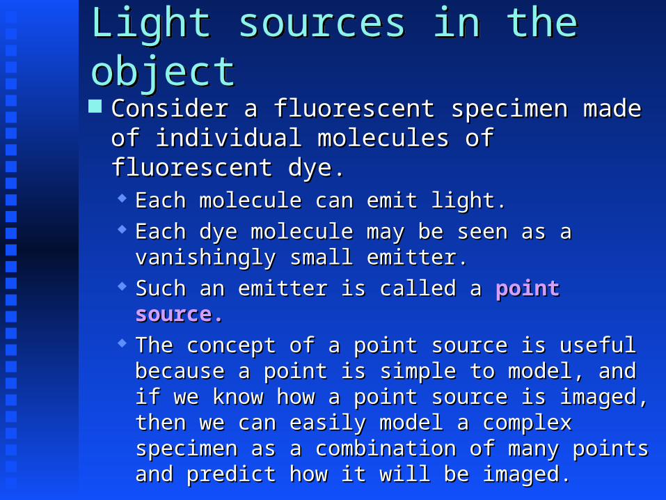
Light sources in the objectLight sources in the object Consider a fluorescent specimen made Consider a fluorescent specimen made of individual molecules of of individual molecules of fluorescent dye.fluorescent dye. Each molecule can emit light.Each molecule can emit light. Each dye molecule may be seen as a Each dye molecule may be seen as a vanishingly small emitter.vanishingly small emitter.
Such an emitter is called a Such an emitter is called a point point source.source.
The concept of a point source is useful The concept of a point source is useful because a point is simple to model, and because a point is simple to model, and if we know how a point source is imaged, if we know how a point source is imaged, then we can easily model a complex then we can easily model a complex specimen as a combination of many points specimen as a combination of many points and predict how it will be imaged.and predict how it will be imaged.

Fluorescence Microscope
Objective
Arc Lamp
Emission Filter
Excitation Diaphragm
Ocular
Excitation Filter

Light sources in the objectLight sources in the object A specific example might be a A specific example might be a microscope slide containing microscope slide containing cells stained with cells stained with fluorescent dye.fluorescent dye.
In an ideal image, a point In an ideal image, a point source would show intensity source would show intensity in only one pixelin only one pixel

In reality, the light from each In reality, the light from each point in the specimen is seen to point in the specimen is seen to spread out and affect many pixels spread out and affect many pixels in the image.in the image.
This “spreading” is an inescapable This “spreading” is an inescapable result of the optical properties result of the optical properties of the image formation system. of the image formation system.
The mathematical description of The mathematical description of this spreading or blurring process this spreading or blurring process is called a is called a point-spread function point-spread function (PSF)(PSF)
Point-spread functionPoint-spread function

Point-spread functionPoint-spread function
The point-spread function (PSF) The point-spread function (PSF) is determined by the optics of is determined by the optics of the image formation system, the image formation system, including factors such as the including factors such as the refractive index, diameter and refractive index, diameter and magnification of its componentsmagnification of its components
The resulting blurred region in The resulting blurred region in the image can be approximated by the image can be approximated by a 2D Gaussian distributiona 2D Gaussian distribution

Realistic Image of a Point SourceRealistic Image of a Point Source
-3 -2 -1 0 1 2 3-3
-2
-1
0
1
23
0.00
0.02
0.04
0.06
0.08
0.10
0.12
0.14
0.16
Intensity
X
Y
This graph shows intensity on the z-This graph shows intensity on the z-axis for a PSF defined in the X-Y axis for a PSF defined in the X-Y plane.plane.
Later we will consider a PSF defined Later we will consider a PSF defined in three dimensions. in three dimensions.

Light sources in the objectLight sources in the object Thus, when a 2D image is acquired, each Thus, when a 2D image is acquired, each point in the specimen will be blurred in point in the specimen will be blurred in all directions and will contribute to the all directions and will contribute to the recording in many pixels around that recording in many pixels around that pixel to which it directly correspondspixel to which it directly corresponds

Introduction to 3D MicroscopyIntroduction to 3D Microscopy The spreading of light from a The spreading of light from a point source actually occurs point source actually occurs in three dimensions as will be in three dimensions as will be shown.shown.
First, however, it is First, however, it is necessary to understand the necessary to understand the three dimensional (3D) nature three dimensional (3D) nature of the object and image as of the object and image as acquired via 3D microscopy.acquired via 3D microscopy.

When a microscope is When a microscope is focused on a specimen, the focused on a specimen, the detector records an image detector records an image from a plane. from a plane. This is the This is the focal planefocal plane.. Parts of the specimen in Parts of the specimen in the focal plane are in the focal plane are in the best focus.the best focus.
DetectorDetector
FocalFocalplaneplane
3D Microscopy3D Microscopy
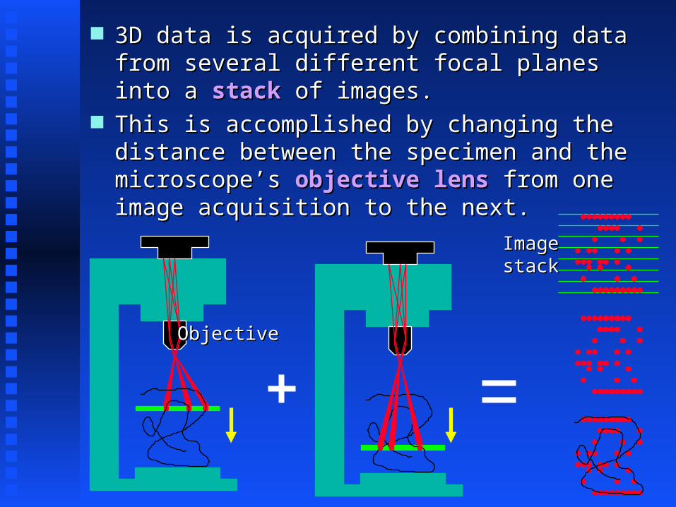
3D data is acquired by combining data 3D data is acquired by combining data from several different focal planes from several different focal planes into a into a stackstack of images. of images.
This is accomplished by changing the This is accomplished by changing the distance between the specimen and the distance between the specimen and the microscope’s microscope’s objective lens objective lens from one from one image acquisition to the next.image acquisition to the next.
ObjectiveObjective
ImageImagestackstack

The next slide shows a real 3D The next slide shows a real 3D image stack.image stack.
The specimen is a HeLa cell The specimen is a HeLa cell labeled with a antibody against labeled with a antibody against the cytoskeletal protein tubulin the cytoskeletal protein tubulin and a secondary antibody and a secondary antibody conjugated to a fluorescent dye.conjugated to a fluorescent dye.
The images were acquired using a The images were acquired using a confocal fluorescence microscope.confocal fluorescence microscope.
The image stack is presented here The image stack is presented here as a movie with one acquired image as a movie with one acquired image plane per movie frame.plane per movie frame.
Real 3D image dataReal 3D image data

Microtubules in a human cellMicrotubules in a human cell
Courtesy of Meel Velliste
QuickTime™ and a decompressor
are needed to see this picture.

Now, with a better understanding Now, with a better understanding of what makes up a 3D image stack, of what makes up a 3D image stack, we can better consider how light we can better consider how light from a point source spreads out from a point source spreads out and is imaged in three dimensions.and is imaged in three dimensions.
On the following slide, intensity On the following slide, intensity is shown by variation in color. is shown by variation in color. Warm colors indicate greater Warm colors indicate greater intensity.intensity.
All axes indicate real spatial All axes indicate real spatial dimensions as indicated.dimensions as indicated.
Real 3D image of a point sourceReal 3D image of a point source

Real 3D image of a point sourceReal 3D image of a point source
y z
x x
Courtesy of Image & Graphics Inc.: Courtesy of Image & Graphics Inc.: http://www.imagepro.co.kr/http://www.imagepro.co.kr/
3D Reconstruction3D Reconstructionof Point Spread Function (PSF)of Point Spread Function (PSF)from 0.2 Micron Beadfrom 0.2 Micron Bead
NOTE: Spreading along the Z-axis is more pronounced.NOTE: Spreading along the Z-axis is more pronounced.
Increasing intensityIncreasing intensity

Image FormationImage Formation
Image formation can be Image formation can be described as:described as: the the convolutionconvolution of an array of an array describing the original specimen describing the original specimen or object or object
with a with a functionfunction describing the describing the image formation system image formation system
to yield an acquired image. to yield an acquired image.

A convolution may be written in somewhat A convolution may be written in somewhat simplified mathematical form as follows:simplified mathematical form as follows:
The concept of a convolutionThe concept of a convolution
i(x,y,z) defines the image in its 3D space i(x,y,z) defines the image in its 3D space according to the form of the equation above.according to the form of the equation above.
PSF(x-x’,y-y’,z-z’) defines the amount of light PSF(x-x’,y-y’,z-z’) defines the amount of light from a point source at x’,y’,z’ that will be from a point source at x’,y’,z’ that will be observed at x,y,zobserved at x,y,z
o(x’,y’,z’) describes the specimen or object.o(x’,y’,z’) describes the specimen or object.
i(x, y, z) = PSF(x−x' , y−y' , z−z' ) • o(x' , y' , z' )dV'∫∫∫

Image FormationImage Formation
The mathematical view of The mathematical view of convolution emphasizes that convolution emphasizes that each point in the sample can each point in the sample can contribute to each point in contribute to each point in the imagethe image

Widefield Fluorescence Microscopy
•This type of fluorescence microscope collects light emitted from all points in the specimen (with varying efficiencies depending on position relative to focal plane)
•The result for specimens that are thick relative to the depth of focus of the objective is a blurred image
Confocal MicroscopyConfocal Microscopy
One way to obtain images that One way to obtain images that better represent the better represent the fluorescence distribution fluorescence distribution just in the focal plane is to just in the focal plane is to use a use a confocalconfocal microscopemicroscope

ConfocalMicroscope Principle
Objective
Laser
Emission Pinhole
Excitation Pinhole
PMT
EmissionFilter
Excitation Filter

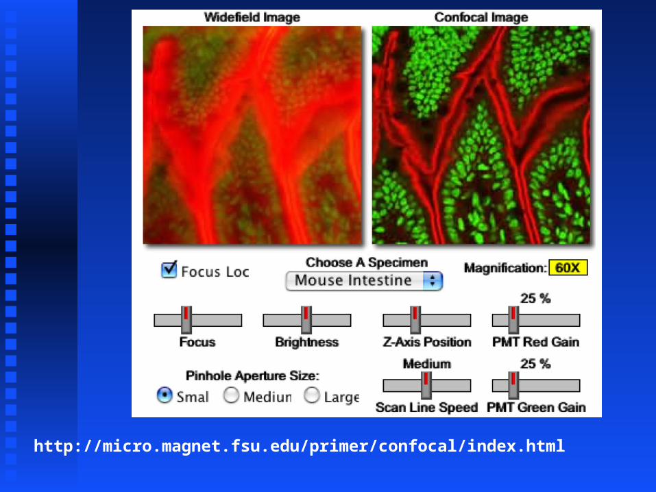
http://micro.magnet.fsu.edu/primer/confocal/index.html
http://micro.magnet.fsu.edu/primer/confocal/index.html


Benefits of Confocal MicroscopyBenefits of Confocal Microscopy Reduced blurring of the image from Reduced blurring of the image from light scatteringlight scattering
Increased effective resolutionIncreased effective resolution Improved signal to noise ratioImproved signal to noise ratio Clear examination of thick specimensClear examination of thick specimens Z-axis scanningZ-axis scanning Depth perception in Z-sectioned imagesDepth perception in Z-sectioned images Magnification can be adjusted Magnification can be adjusted electronicallyelectronically

Drawbacks of Confocal MicroscopyDrawbacks of Confocal Microscopy Slower acquisition - need to Slower acquisition - need to collect one pixel at a timecollect one pixel at a time
Increased photodamage Increased photodamage (photobleaching) due to (photobleaching) due to longer exposure to exciting longer exposure to exciting lightlight
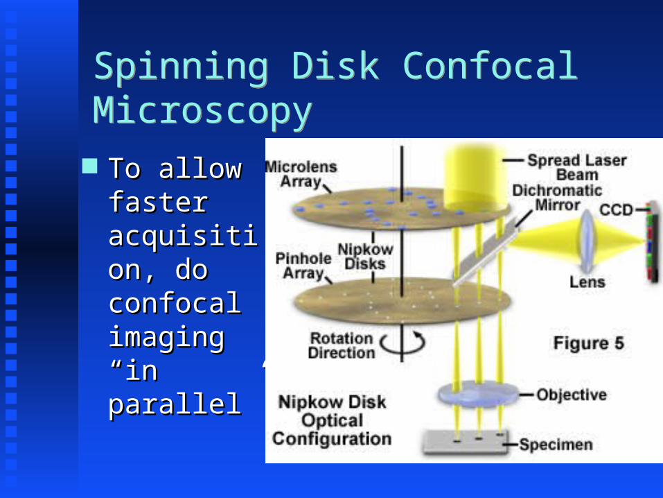
Spinning Disk Confocal MicroscopySpinning Disk Confocal Microscopy
To allow To allow faster faster acquisitacquisition, do ion, do confocal confocal imaging imaging “in “in parallelparallel””

Image FormatsImage Formats
An bit map image normally consists An bit map image normally consists of an 8-bit or 16-bit value for each of an 8-bit or 16-bit value for each pixel.pixel.
These values are stored as computer These values are stored as computer files in various formats.files in various formats.
Pixel values are normally stored Pixel values are normally stored linearly in a file with the values linearly in a file with the values for the first row of pixels followed for the first row of pixels followed immediately by the values for the immediately by the values for the second row (etc.).second row (etc.).

Image FormatsImage Formats At a minimum, an image format At a minimum, an image format contains:contains: Image size (# of rows and columns)Image size (# of rows and columns) Number of bits per pixelNumber of bits per pixel Order in which bytes within words are Order in which bytes within words are storedstored
Number of bytes to skip at the beginning Number of bytes to skip at the beginning of the image (the of the image (the offsetoffset))
The beginning of image files often has a text The beginning of image files often has a text headerheader that can be skipped if the above values that can be skipped if the above values are known.are known.
This header may contain additional descriptive This header may contain additional descriptive information about the image such as:information about the image such as:• subject of imagesubject of image• name of person and/or application creating the imagename of person and/or application creating the image

Common Image File FormatsCommon Image File Formats TIFF (Tag Image File Format)TIFF (Tag Image File Format)
Originally for scanners and Originally for scanners and frame grabbersframe grabbers
Used extensively on many platformsUsed extensively on many platforms Can be read/written by NIH ImageCan be read/written by NIH Image Supports lossless compressionSupports lossless compression
Reference: www.shortcourses.com/chapter07.htmReference: www.shortcourses.com/chapter07.htm
Common Image File FormatsCommon Image File Formats
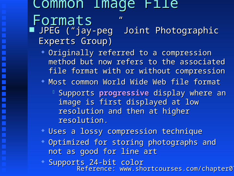
JPEG (“jay-peg” Joint Photographic JPEG (“jay-peg” Joint Photographic Experts Group)Experts Group) Originally referred to a compression Originally referred to a compression method but now refers to the associated method but now refers to the associated file format with or without compressionfile format with or without compression
Most common World Wide Web file formatMost common World Wide Web file format Supports Supports progressiveprogressive display where an display where an image is first displayed at low image is first displayed at low resolution and then at higher resolution and then at higher resolution.resolution.
Uses a lossy compression techniqueUses a lossy compression technique Optimized for storing photographs and Optimized for storing photographs and not as good for line artnot as good for line art
Supports 24-bit colorSupports 24-bit colorReference: www.shortcourses.com/chapter07.htmReference: www.shortcourses.com/chapter07.htm
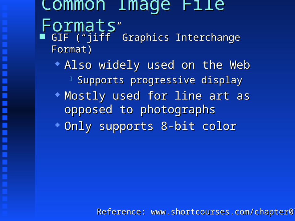
Common Image File FormatsCommon Image File Formats GIF (“jiff” Graphics Interchange GIF (“jiff” Graphics Interchange Format)Format) Also widely used on the WebAlso widely used on the Web
Supports progressive displaySupports progressive display Mostly used for line art as Mostly used for line art as opposed to photographsopposed to photographs
Only supports 8-bit colorOnly supports 8-bit color
Reference: www.shortcourses.com/chapter07.htmReference: www.shortcourses.com/chapter07.htm