Embed Size (px)
Citation preview

Thulasiraman, M., et al.: Computational Fluid Dynamic Analysis on the Effect of ... THERMAL SCIENCE: Year 2017, Vol. 21, No. 6B pp. 2883-2895 2883
COMPUTATIONAL FLUID DYNAMIC ANALYSIS ON THE EFFECT
OF PARTICLES DENSITY AND BODY DIAMETER IN A
TANGENTIAL INLET CYCLONE HEAT EXCHANGER
by
Mothilal THULASIRAMANa,*
and Pitchandi KASIVISWANATHANb
a Department of Mechanical Engineering, T. J. S. Engineering College, Gummidpoondi, India b Department of Mechanical Engineering, Sri Venkateswara College of Engineering,
Sriperumbudur, India Original scientific paper
https://doi.org/10.2298/TSCI151105055T
This work presents the effect of particles density and body diameter on hold up mass and heat transfer rate in cyclone heat exchanger by using CFD analysis. Performance of cyclone heat exchanger is based on operational and geometrical parameters which mainly depend on inlet air velocity and solid particles parame-ters. Present work studies the effect of particles density, diameter of cyclone, inlet air velocity, and temperature on performance of cyclone heat exchanger. The RNG k-ε turbulence model was adopted in ANSYS FLUENT 12.0 software to ana-lyze the flow field and discrete phase model is adopted to predict tracking of solid particles in cyclone. Solid particles density ranges from 2050 to 8950 kg/m
3 for
different materials fed at 0.5 g/s flow rate and inlet air velocity ranges from 5 to 25 m/s at three inlet air temperature 373, 473, and 573 K for 100, 200, and 300 mm body diameter cyclone heat exchangers. Results conclude that increase in di-ameter of cyclone increases hold up mass and heat transfer rate whereas in-crease in density of particles decreases the hold up mass and heat transfer rate. Experimental set-up was built for Stairmand high efficiency cyclone and good agreement was found between simulation and experimental result. New correla-tion was proposed for non-dimensional hold up mass. Correlation compared with experimental hold up mass and predicts experimental value within an error band of –3 to 6%.
Key words: particles density, hold up mass, cyclone heat exchanger, RNG k-ɛ model, discrete phase model, correlation
Introduction
In various industries such as cement production, fertilizer, chemical processing,
and powder industries cyclones are used to remove dispersed particle from carrying gas.
Cyclones are one of the oldest methods of particle separation and it can operate at high
loading conditions (temperature and pressure). Heat exchangers are used for efficient trans-
fer of heat through convection between two fluids. In tangential inlet cyclone heat exchang-
er fluid and solid mixture enters the cyclone tangentially which generate the swirling mo-
tion of the gas stream, in turn forces particles toward the outer wall where they spiral in the
downward direction. The solid particles gain relative motion in the radial direction and get
* Corresponding author, e-mail: [email protected]

Thulasiraman, M., et al.: Computational Fluid Dynamic Analysis on the Effect of... 2884 THERMAL SCIENCE, Year 2017, Vol. 21, No. 6B pp. 2883-2895
separated from the gaseous stream which is collected in the bin of the cyclone heat ex-
changer. The gaseous stream migrates inwards axially along the cylinder and finally exit
through the vortex finder tube. Swirl induces a centrifugal force (driving force) on solid
particles and particles are dispersed by turbulence, thus swirl and turbulence are the two
competing phenomena in the cyclone. The mechanism of swirl consists of inner vortex
moving toward the cyclone exit and an outer vortex moving in the opposite direction. Due
to presence of particles, the intensity of swirl and turbulence gets reduced. The reduction of
swirl is mostly felt in the free-vortex part as the particle concentrations are much higher
than in the core. In case of a cyclone heat exchanger hold up mass of the particles i. e.
amount of particle undergoing heat transfer at any instance of time within the cyclone body,
has not been discussed so far. Although cyclone heat exchanger has these many credentials,
the studies on the subject are at a very minimum extent.
Azadi et al. [1] analyzed numerically flow patterns on different cyclone size and
observe enhance in cut off diameter and pressure drop with increase in cyclone size. Gas-
solid flow inside the cyclone separator was analyzed numerically and experimentally for
separation efficiency of particles at different entries [2]. Numerous studies have been per-
formed on cyclone pressure drop by varying operational and geometrical parameters [3-5].
Elsayed and Lacor [6-9] analyzed different geometrical parameters like inlet height, dust
outlet and cone tip diameter of cyclone on its flow patterns and performance. Karagoz and
Kaya [10] studied the structure of vortices and variation of local heat transfer by varying
inlet velocity of gas and particle feed rate. Correlation for dimensional Nusselt number was
predicted by varying inlet parameters of cyclone heat exchanger [11]. Bohnet et al. [12]
developed a model, in which temperature dependent wall friction coefficient was introduced
and re-entrainment of separated particles were considered. Dust load has strong influence
on collection efficiency and loading effect are stronger at high temperature [13]. Zhu and
Lee [14] carried experiment on collection efficiency in small cyclones by changing exit
tube length and cylinder height at high flow rates and observed that flow rate plays signifi-
cant role in cyclone collection efficiency. Hoekstra et al. [15] experimentally analyzed dif-
ferent geometric swirl numbers by laser-Doppler velocimetry. Geometry swirl number has
influence on mean flow characteristics and maximum tangential velocity influences vortex
size. Different numerical schemes for dispersed phase were evaluated in cyclone separator
[16]. Xiang and Lee [17] numerically evaluated different cyclone height for flow pattern
and separation efficiency. Mothilal and Pitchandi [18] analyzed numerically effect of inlet
mass flow rate of air and solid on hold up mass and heat transfer rate, found new correlation
for hold up mass by varying inlet air velocity and particle feed rate. The effect of mass flow
rate of inlet air on hold up mass experimentally observed [19]. Geometries of cyclone heat
exchanger such as vortex finder diameter, inlet height and cone tip diameter are varied to
find its effect on flow field, hold up mass, and heat transfer rate [20, 21]. The entire models
developed were reviewed for the flow field inside inverse flow cyclone separator [22].
Performance of cyclone heat exchanger depends on hold up mass of the solid
particles within the cyclone. The present work elaborates the hold up mass and heat trans-
fer characteristics at the various particles density, inlet velocity of air and temperature on
three different cyclone (C1, C2, and C3) heat exchangers. Previous work applies the cy-
clone principle to separate particles from dust laden gas whereas present work makes the
first attempt to analyze the cyclone as a heat exchanger and predicts the correlation for
hold up mass.

Thulasiraman, M., et al.: Computational Fluid Dynamic Analysis on the Effect of ... THERMAL SCIENCE: Year 2017, Vol. 21, No. 6B pp. 2883-2895 2885
Numerical descriptions
Governing equation for gas phase
Fluid flows are mathematically described by Reynolds-Average Navier-Stokes
(RANS) equation. For steady and incompressible flow the equation for continuity and mo-
mentum is given as [10,18].
0i
i
u
x
(1)
' '2
g3
ji ii j i ij i j
i i j j i i j
uu uPu u u u
x x x x x x x
(2)
Turbulent equations for gas phase
For swirling turbulent flow in cyclone heat exchanger there are several turbulence
models available in FLUENT. The RNG k-ε model well predicts the experimental results [10,
18] therefore RNG k-ε was employed for present work and its transport equation is shown:
effi k k mi j j
kk ku G Y
t x x x
(3)
2
eff 1 2i ki j j
u C G C Rt x x x k k
(4)
where C1ε = 1.42 and C2ε = 1.68 [18, 23].
Model equation for particles phase
In this study spherical particles gets dispersed and diluted into gas phase, gas-solid
interaction and effect of the dispersed particles volume fraction on gas phase is negligibly
small. As the particle volume fraction (less than 1% ) and mass loading is lower in a cyclone,
Lagrange approach is used to simulate particle transport in CFD analysis [1, 2, 4, 6]. The
Eulerian-Lagrangian approach adopts a continuum description for the fluid phase and tracks
the discrete phase using Lagrangian particle trajectory analysis. Generally particles loading in
cyclone is small (3-5%), so flow field in the cyclone is not affected by the presence of parti-
cles, therefore one way coupling is adopted for simulation [4, 16]. Interaction among the par-
ticles is neglected due to dilute flow. Discrete phase model (DPM) is used to simulate the
particles motion in the cyclone [5, 16, 18]. Trajectories of particles are obtained by integrating
the force balance on the particles. Equation of motion of small particles in terms of the Euleri-
an-Lagrangian approach is given by [16, 18].
d g
d
p x p
D p xp
uF u u F
t
(5)
The FD is the drag force per unit particles mass and:
Re18
2 24
CDFD
dp p
(6)

Thulasiraman, M., et al.: Computational Fluid Dynamic Analysis on the Effect of... 2886 THERMAL SCIENCE, Year 2017, Vol. 21, No. 6B pp. 2883-2895
Here, u is the fluid phase velocity, up – the particles velocity, μ – the molecular vis-
cosity of the fluid, ρ – the fluid density, ρp – the density of the particles, dp – the particles
diameter, and Re is the relative Reynolds number is given by:
Rep pd u u
(7)
The Fx denotes the additional forces per unit mass such as Staffman lift force,
Brownian force, Basset and virtual force [7, 16]. Due to low value of gas to particle density
ratio, low inertia and particle size, neglects Basset force, Saffman lift force, and Brownian
motion of the particles respectively when compare to the drag force of the particle [7, 16]
Turbulent dispersion of particles
Reynolds average (RANS) turbulence model provide only the average velocity field,
as small particles are injected, the effect of instantaneous fluctuation of gas velocity on turbu-
lent dispersion of small particles has to be considered and therefore it is necessary to include a
turbulence dispersion model. The dispersion of particles due to turbulence in the fluid phase is
predicted using the stochastic tracking model [7, 16]. The stochastic tracking (random walk)
model includes the effect of instantaneous turbulent velocity fluctuations on the particle tra-
jectories through the use of stochastic methods. The turbulent dispersion of small particles
was taken into account by integrating the trajectory equations for individual particles using
the instantaneous fluid velocity [7, 16]:
u u u (8)
where u is instantaneous velocity, u – the mean gas velocity, and u – the fluctuation gas
velocity.
Geometrical descriptions
Numerical simulation of cyclone heat exchanger performed on Stairmand high effi-
ciency cyclone which collects more particles [3, 4, 18]. Dimension of various parts of three
different cyclones are shown in tab.1, and 2-D view is shown in fig.1. The 3-D model of cy-
clone is constructed by SOLIDWORKS modeling software.
Discretization of cyclone and boundary conditions
Mesh was generated using non-uniform hybrid mesh [10] in cyclones by using AN-
SYS ICEM CFD [18, 24] software. Grid of 197789 cells, 25030 nodes for C1, 219140 cells,
38781 nodes for C2, and 330673 cells, 82212 nodes for C3. Mesh generated cyclones are
shown in fig. 2. The boundary condition at gas entrance and solid entrance was given as ve-
locity inlet which means that the velocity and direction is specified. Intensity of cyclone is set
as 5% [4, 16, 18] and hydraulic diameters in gas and solid for C1 is 0.036 m, C2 is 0.072 m,
Table 1. Details of cyclone heat exchanger geometry
(All dimensions are in mm)
Cd De S Ds Da Ls Lb Lc Lp D Lcc Bd Bh W H
C1 37.5 50 50 36 36 100 150 250 200 100 50 50 50 20 50
C2 75 100 100 72 72 200 300 500 400 200 100 100 100 40 100
C3 112.5 150 150 108 108 300 450 750 600 300 150 150 150 60 150

Thulasiraman, M., et al.: Computational Fluid Dynamic Analysis on the Effect of ... THERMAL SCIENCE: Year 2017, Vol. 21, No. 6B pp. 2883-2895 2887
and C3 is 0.108 m. Outflow boundary condition was set at gas outlet and trap DPM condition
was applied at the bin in order to track all particles. In wall boundaries no slip condition was
set and co efficient of restitution of particles is 0.8 [16,18].
Numerical methods and grid independence
Gas-flow is steady, incompressible and 3-D solved by RANS equation. The meth-
odologies used for simulation is displayed in tab. 2. Mesh independence study has been done
for tested cyclones. For each cyclone four levels of meshes: 91264, 143273, 197789, and
238427 elements for C1, 98583, 145267, 219140, and 245161 elements for C2, and 225611,
277777, 330673, and 372003 elements for C3 was generated in ICEM [24] environment, re-
spectively. These grids are imported to CFD software and single phase gas-flow is analyzed
for pressure drop. Static pressure of C1, C2, and C3 were predicted at gas outlet for inlet air
velocity of 10 m/s. Maximum difference between the pressure drops is lesser than 1% for grid
systems 197789 and 238427 elements for C1, 219140 and 245161 elements for C2, and
330673 and 372003 for C3,
respectively. Considering the
computational time and accu-
racy, cyclone model with
197789, 219140, and 330673
elements for cyclones C1, C2,
and C3, respectively, were
taken for simulation.
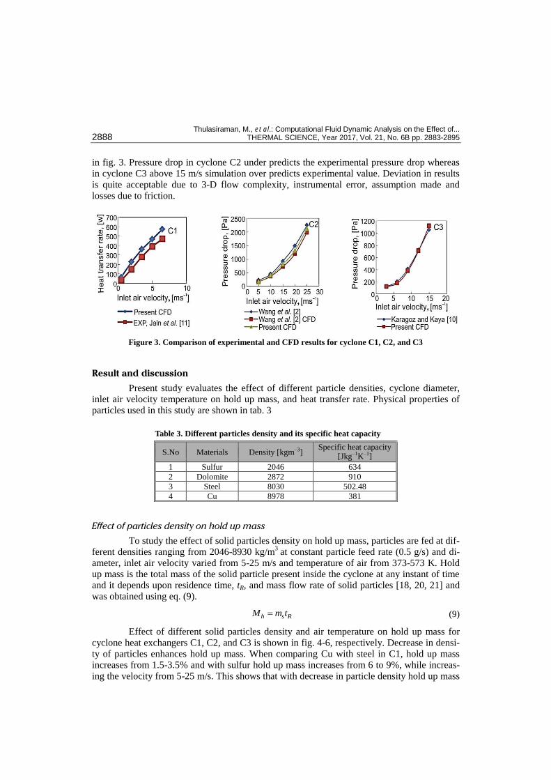
Comparison of experimental and simulation result
Simulation result of cyclone C1 is compared with Jain et al. [11], cyclone C2 is
compared with Wang et al. [2], and C3 cyclone is compared with Karagoz and Kaya [10], for
same inlet parameters and present simulation value well similar with literature values shown
Table 2. Methodologies for simulation
S. No Description Scheme
1 Pressure description Standard
2 Pressure velocity coupling SIMPLE
3 Momentum Second order upwind
4 Turbulent kinetic energy Second order upwind
5 Turbulent dissipation rate Second order upwind
Figure 1. The 2-D view of the cyclone heat exchanger
Figure 2. Mesh generation of cyclone heat
exchanger
Thulasiraman, M., et al.: Computational Fluid Dynamic Analysis on the Effect of... 2888 THERMAL SCIENCE, Year 2017, Vol. 21, No. 6B pp. 2883-2895
in fig. 3. Pressure drop in cyclone C2 under predicts the experimental pressure drop whereas
in cyclone C3 above 15 m/s simulation over predicts experimental value. Deviation in results
is quite acceptable due to 3-D flow complexity, instrumental error, assumption made and
losses due to friction.
Result and discussion
Present study evaluates the effect of different particle densities, cyclone diameter,
inlet air velocity temperature on hold up mass, and heat transfer rate. Physical properties of
particles used in this study are shown in tab. 3
Effect of particles density on hold up mass
To study the effect of solid particles density on hold up mass, particles are fed at dif-
ferent densities ranging from 2046-8930 kg/m3
at constant particle feed rate (0.5 g/s) and di-
ameter, inlet air velocity varied from 5-25 m/s and temperature of air from 373-573 K. Hold
up mass is the total mass of the solid particle present inside the cyclone at any instant of time
and it depends upon residence time, tR, and mass flow rate of solid particles [18, 20, 21] and
was obtained using eq. (9).
h s RM m t (9)
Effect of different solid particles density and air temperature on hold up mass for
cyclone heat exchangers C1, C2, and C3 is shown in fig. 4-6, respectively. Decrease in densi-
ty of particles enhances hold up mass. When comparing Cu with steel in C1, hold up mass
increases from 1.5-3.5% and with sulfur hold up mass increases from 6 to 9%, while increas-
ing the velocity from 5-25 m/s. This shows that with decrease in particle density hold up mass
Table 3. Different particles density and its specific heat capacity
S.No Materials Density [kgm–3] Specific heat capacity
[Jkg–1K–1]
1 Sulfur 2046 634
2 Dolomite 2872 910
3 Steel 8030 502.48
4 Cu 8978 381
Figure 3. Comparison of experimental and CFD results for cyclone C1, C2, and C3

Thulasiraman, M., et al.: Computational Fluid Dynamic Analysis on the Effect of ... THERMAL SCIENCE: Year 2017, Vol. 21, No. 6B pp. 2883-2895 2889
increases. Similar result was found for cyclone C2 and C3. In C1 hold up mass of sulfur is 0.5 g
at 5 m/s and 0.65 g at 25 m/s, similarly for C2 is 0.75 g at 5 m/s and 1.15 g at 25 m/s and for
C3 is 1.05 g at 5 m/s and 1.20 g at 25 m/s. This shows that hold up mass increases with in-
crease in cyclone body diameter in a range of 5 to 18%. Similar trend was observed for all
particle materials at all inlet air velocities.
Hold up mass increases with increase in inlet air velocity and temperature. Increase
in inlet air velocity increases the centrifugal force as well as swirling rotation of particles
which carry more amounts of particles inside the cyclone. At all inlet air temperature (373-
C1
Figure 4. Effect of solid particles density on holdup mass at different inlet air temperature for C1
Figure 5. Effect of solid particles density on holdup mass at different inlet air temperature for C2
Figure 6. Effect of solid particles density on holdup mass at different inlet air temperature for C3

Thulasiraman, M., et al.: Computational Fluid Dynamic Analysis on the Effect of... 2890 THERMAL SCIENCE, Year 2017, Vol. 21, No. 6B pp. 2883-2895
573 K) for C1 maximum hold up mass of 0.64-0.65 g, for C2 1.15-1.2 g, and for C3 1.32-1.46
g is obtained at 25 m/s. Thus the hold up mass increases with inlet air temperature. Particle
trajectories of residence time for Cu and Sulphur particle in C1 cyclone are shown in fig. 7.
The colored legends indicate the residence time of the particles. The Cu particle takes 0.86
seconds to reach bin whereas Sulphur particle needs 0.93 seconds to reach bin. Number of
swirling rotation decreases with increase in density of particles. Increase in density of parti-
cles raises drag force acting on particles, which lead to loss in swirling rotation inside cyclone
and residence time of particles (time taken by the particles to reach the bin from its inlet).
Similar trend of results were observed for C2 and C3 cyclones.
Effect of particles density on heat transfer rate
Heat transfer rate of the particles is related with mass flow rate, specific heat capaci-
ty and temperature difference between inlet and outlet temperature of particles [11, 25] and
shown in eq. (10):
Sout Sins psq m C T T (10)
The effect of particles density of C1, C2, and C3 on heat transfer rate is shown in
fig. 8, respectively. Heat transfer rate increases with rise in heat capacity of particles and high
for dolomite compared to other particles even though particle residence time is less than steel,
which indicates that heat transfer rate depends upon heat capacity of particle than particle
residence time and hold up mass. Increase in diameter of cyclone increases the contact time
between particles and air, thus the heat transfer rate increased. Increasing the cyclone diame-
ter from C1 to C2 the heat transfer rate increased to 20% at 373 K and similar result was ob-
served for C2 to C3 for all particles and temperatures.
It is also clear that increase in inlet air velocity increases the heat transfer rate due to
increase in mass flow rate of air which increases the availability of air for heat transfer. Max-
imum heat transfer rate occurs at 5-10 m/s (15-25%) for all particles in C1 and similar result
Figure 7. Single particle trajectories for different materials (for color image see journal web site)

Thulasiraman, M., et al.: Computational Fluid Dynamic Analysis on the Effect of ... THERMAL SCIENCE: Year 2017, Vol. 21, No. 6B pp. 2883-2895 2891
was observed for C2 and C3. Increasing the temperature of inlet air from 373-473 K, heat
transfer rate increases 1.2-1.5 times and when increasing 473-573 K, heat transfer rate in-
creases 0.5-0.8 times in C1. Similar result was observed for C2 and C3 cyclone for all particles.
Experimental description
Experimental set-up of present work is displayed in fig. 9. It consists of an air inlet
pipe connected with blower, solid particles feeder, cyclone separator, valve arrangements, and
bin. Feeder section consists of an electromagnetic vibrator connected to a particle discharge
unit. Particles are fed in to inlet pipe through a hopper and inlet pipe is joined to cyclone with
a geometrical transition part from circular to rectangular. To calculate temperature of air and
solid particles, thermocouples are placed at various parts of cyclone body. Set-up is fitted with
instruments to measure flow rate of air and solid particles. Experiment is insulated with asbes-
tos rope in order to prevent the heat loss. Pressure gauges are used to measure pressure drop at
inlet and outlet. Air and solid feed rate was controlled by varying the inlet valves, respective-
Figure 8. Effect of particles density on heat transfer rate for C1, C2, and C3 (for color image see journal web site)

Thulasiraman, M., et al.: Computational Fluid Dynamic Analysis on the Effect of... 2892 THERMAL SCIENCE, Year 2017, Vol. 21, No. 6B pp. 2883-2895
ly. Uncertainty in the measurement of exit temperature is ±1 ºC. The collected solids are
weighed on Infradigital precision balance having model number IN200 manufactured by In-
fratech, Mumbai, India, with a least count of 0.01 g.
Experimental procedure
Desired flow rate of air was set by inlet
valve and atmospheric air is drawn from the
blower which enters heater through inlet pipe.
Solid particles fed to the hopper through elec-
tromagnetic arm imparting machine which is
fitted in the inlet pipe. Steady solid feed rate is
achieved for particular combination of gas
velocity, particle size, and funnel opening. Mix-
ture of gas and solid phase enters tangentially
into the exchanger where heat transfer takes
place between gas to solid. Temperature of air
from inlet to outlet was measured using ther-
mocouples at various parts of cyclone heat
exchanger. Solid particles are collected in bin.
At any instant of time hold up mass in cyclone heat exchanger was calculated by closing both
inlet and outlet valve of gas and particles flow simultaneously. Particles collected in bin are
weighted to calculate the mass (hold up mass) of solid particles. In order to ensure the reliabil-
ity of data, four random measurements were taken for each experimental reading.
Prediction of new correlation for
dimensionless hold up mass
Correlation is developed from obtained computational result by dimensional and re-
gression analysis. Correlation coefficients and exponents were estimated using regression
analysis. Hold up mass is a function of flow rate of air, flow rate of solid particles, cyclone
body diameter, diameter of particle, and particle density [18].
, , , , h g s pM f m m D d (10)
Variables are grouped into non-dimensional group by using Buckingham Π solution
theorem. Three Π values are generated from Dimensional analysis [11, 18]:
31 h
p
M
D (12)
2 s
g
m
m (13)
3d
D (14)
where Π1 is a dimensionless hold up and Π values are arranged together to derive correlation
[18]:
Figure 9. Experimental set-up of cyclone heat exchanger

Thulasiraman, M., et al.: Computational Fluid Dynamic Analysis on the Effect of ... THERMAL SCIENCE: Year 2017, Vol. 21, No. 6B pp. 2883-2895 2893
1 2
3
a ah s
gp
M m d
m DD
(15)
Coefficient values of eq. (14) obtained by regression technique are grouped to form
the equation:
–0.13013 2.6054
3165.574h s
gp
M m d
m DD
(16)
These correlation is valid for mass flow
rate of solid (ms) to air (mg) ratio from 0.00401-
0.8019, density of particles from 2050-8978
kg/m3 and ratio of diameter of particles, d, to
diameter of cyclone, D, varies from 0.001-0.003.
Predicted correlation compared with experi-
mental Π1 value and result is displayed in fig.
10. It indicates good relation between proposed
correlation Π1 and experimental Π1, with error
band of –3 to +6%.
Conclusions
In this paper the simulation done in k-ε RNG turbulence model and DPM for particle
trajectory to find effect of particles density and
diameter of cyclone heat exchanger on hold up
mass and heat transfer rate in the Stairmand high efficiency cyclone. Hold up mass of the
particles decreases with increase in inlet particle density whereas increases with increase in
cyclone diameter. Heat transfer rate increases with decrease in density of particles as well as
increase in specific heat capacity of particles and body diameter of cyclone. Correlation is
predicted for non-dimensional hold up mass and it is compared with experimental hold up
mass that predicts experimental value within an error range of –3 to +6%. Correlation is valid
only for mass flow rate of solid to air ranges from 0.00401-0.8019, diameter of particles to
diameter of cyclone ranges from 0.001-0.003. This work can be extended to find generalized
correlation for hold up mass without compensating collection efficiency by varying cyclone
geometry dimensions.
Nomenclature
Bd – bin diameter, [mm] Bh – bin height, [mm] CD – drag coefficient Cd – gas outlet, [mm] Cps – specific heat of solid particle, [Jkg–1K–1] D – cyclone diameter, [mm] Da – gas inlet diameter, [mm] De – gas outlet, [mm] Ds – solid particle inlet diameter, [mm] d – diameter of solid particles, [μm] Gk – generation of turbulence kinetic energy gx – gravitational acceleration, [ms–2]
H – height of rectangle inlet, [mm] k – turbulent kinetic energy, [m2s–2] Lb – cyclone body length, [mm] Lc – cone length, [mm] Lcc – connector length, [mm] Lp – duct length, [mm] Ls – particle hopper length, [mm] Mh – hold up mass, [g] mg – mass flow rate of the air, [kgs–1] ms – mass flow rate of the
solid particles, [kgs–1] P – mean pressure, [Pa]
Figure 10. Comparison of experimental and correlation Π1 value

Thulasiraman, M., et al.: Computational Fluid Dynamic Analysis on the Effect of... 2894 THERMAL SCIENCE, Year 2017, Vol. 21, No. 6B pp. 2883-2895
q – heat transfer rate, [W] Re – additional term in the e equation S – vortex pipe height, [mm] TSin – inlet temperature of solid particle, [K] TSout – outlet temperature of solid particle, [K] t – flow physical time, [s] tR – particle residence time, [s] u – instantaneous velocity, [ms–2] ui – flow velocity component in i direction,
[ms–1] uj – flow velocity component in j direction,
[ms–1] u¢ – dispersion velocity, [ms–1] W – width of the rectangle inlet, [mm]
xi – position in i direction, [m] Ym – fluctuating dilatation in compressible
turbulence
Greek symbols
αk – inverse effective Prandtl number for k αε – inverse effective Prandtl number for ε d – Kronecker delta ε – turbulent dissipation rate, [m2s–3] µ – molecular viscosity of fluid, [kgm–1s–1] – drag coefficient defined as per the equation r – fluid density, [kgm–3] ρp – density of solid particles, [kgm–3]
References
[1] Azadi, M., et al., A CFD Study of the Effect of Cyclone Size on its Performance Parameters, Journal of Hazardous materials,182 (2010), 1-3, pp. 835-841
[2] Wang, B., et al., Numerical Study of Gas–Solid Flow in a Cyclone Separator, Applied Mathematical Modelling, 30 (2006), 11, pp. 1326-1342
[3] Ferit Ficici, et al., The Effects of Vortex Finder on the Pressure Drop in Cyclone Separators, Interna-tional Journal of the Physical Sciences, 5 (2010), 6, pp. 804-813
[4] Elsayed, K., Lacor, C., Optimization of the Cyclone Separator Geometry for Minimum Pressure Drop Using Mathematical Models and CFD Simulations, Chemical Engineering Science, 65 (2010), 22, pp. 6048-6058
[5] Chen, J., Shi, M., A Universal Model to Calculate Cyclone Pressure Drop, Powder Technology, 171 (2007), 3, pp. 181-191
[6] Elsayed, K., Lacor, C., The Effect of Cyclone Inlet Dimensions on the Flow Pattern and Performance, Applied Mathematical Modelling, 35 (2011), 4, pp. 1952-1968
[7] Elsayed, K., Lacor, C., The Effect of the Dust Outlet Geometry on the Performance and Hydrodynamics of Gas Cyclones, Computers &Fluids, 68 (2012), Sept., pp. 134-147
[8] Elsayed, K., Lacor, C., Numerical Modelling of the Flow Field and Performance in Cyclones of Differ-ent Cone-Tip Diameters, Computers &Fluids, 51 (2011), 1, pp. 48-59
[9] Elsayed, K., Lacor, C., The Effect of Cyclone Vortex Finder Dimensions on the Flow Pattern and Per-formance Using LES, Computers & Fluids, 71 (2013), Jan., pp. 224-239
[10] Karagoz, I., Kaya, F., CFD Investigation of the Flow and Heat Transfer Characteristics in a Tangential Inlet Cyclone, International Communications in Heat and Mass Transfer, 34 (2007), 9-10, pp. 1119-1126
[11] Jain, A., et al., Studies on Gas-Solid Heat Transfer in Cyclone Heat Exchanger, Journal of Heat Transfer ASME, 128 (2006), 8, pp. 761-768
[12] Bohnet, M., Influence of the Gas Temperature on the Separation Efficiency of Aerocyclones, Chemical Engineering and Processing: Process Intensification, 34 (1995), 3, pp. 151-156
[13] Patterson, P. A., Munz, R. J., Cyclone Collection Efficiencies at Very High Temperatures, Can. J. Chemical Engineering, 67 (1989), 2, pp. 321-328
[14] Zhu, Y., Lee, K. W., Experimental Study on Small Cyclones Operating at High Flow Rates, Journal of Aerosol Science, 30 (1999), 10, pp. 1303-1315
[15] Hoekstra, A. J., et al., An Experimental and Numerical Study of Turbulent Swirling Flow in Gas Cy-clones, Chemical Engineering Science, 54 (1999), 13-14, pp. 2055-2065
[16] Shukla, S. K., et al., Evaluation of Numerical Schemes for Dispersed Phase Modelling of Cyclone Seperators, Engineering applications of Computational Fluid Mechanics, 5 (2011), 2, pp. 235-246
[17] Xiang, R. B., Lee, K. W., Numerical Study of Flow Field in Cyclones of Different Height, Chemical Engineering and Processing, 44 (2005), 8, pp. 877-883
[18] Mothilal, T., Pitchandi, K., Influence of Inlet Velocity of Air and Solid Particle Feed Rate on Hold up Mass and Heat Transfer Characteristics in Cyclone Heat Exchanger, Journal of Mechanical Science and Technology, 29 (2015), 10, pp. 4509-4518
Thulasiraman, M., et al.: Computational Fluid Dynamic Analysis on the Effect of ... THERMAL SCIENCE: Year 2017, Vol. 21, No. 6B pp. 2883-2895 2895
[19] Mothilal, T., Pitchandi, K.,, Effect of Mass Flow Rate of Inlet Gas on Hold up Mass of Solid Cyclone Heat Exchanger, Applied Mechanics and Materials, 592-594 (2014), July, pp.1498-1502
[20] Mothilal, T., et al., Influence of Vortex Finder Diameter and Cone Tip Diameter on Hold up Mass and Heat Transfer Rate in Cyclone – CFD Approach, International Journal of Applied Engineering Re-search, 10 (2015), 33, pp. 25890-25897
[21] Mothilal, T., et al., The effect of Vortex Finder Diameter and Inlet Height on Hold up Mass and Heat Transfer Characteristics in Cyclone Heat Exchanger-CFD Approach, International Journal of Applied Engineering Research, 10 (2015), 77, pp. 268-272
[22] Cortes, C., Gil, A., Modelling the Gas and Particle Flow Inside Cyclone Separators, Progress in Energy and Combustion Science, 33 (2007), 5, pp. 409-452
[23] ***, Ansys Fluent, Fluent 12. Theory guide, Ansys inc. [24] ***, Ansys ICEM CFD, ICEM CFD Theory guide, Ansys inc. [25] Tomić, M. A., et al., Numerical Study of Perforated Plate Convective Heat transfer, Thermal Science,
18, (2014), 3, pp. 949-956
Paper submitted: November 5, 2015 © 2017 Society of Thermal Engineers of Serbia. Paper revised: February 22, 2016 Published by the Vinča Institute of Nuclear Sciences, Belgrade, Serbia. Paper accepted: February 6, 2016 This is an open access article distributed under the CC BY-NC-ND 4.0 terms and conditions.


![Cyclone Handbook, Section I. Cyclone FPGA Family Data Sheet1]EP1C12F256C8.pdf · Section I. Cyclone FPGA Family Data Sheet ... Cyclone Device Handbook, ... Vertical migration means](https://img.pdfslide.net/doc/110x75/5b3a24897f8b9a600a8f2cfc/cyclone-handbook-section-i-cyclone-fpga-family-data-sheet-1ep1c12f256c8pdf.jpg)