Embed Size (px)
Citation preview

COMPUTATIONAL LASER MICROMACHINING
FOR MACHINING PMMA
TIONG CHUNG SHIA
Report submitted in partial fulfillment of the requirements for the award of the degree of
Bachelor of Mechanical Engineering with Manufacturing Engineering
Faculty of Mechanical Engineering
UNIVERSITI MALAYSIA PAHANG
DECEMBER 2010

SUPERVISOR’S DECLARATION
I hereby declare that I have checked this project and in my opinion, this project is
adequate in terms of scope and quality for the award of the degree of Bachelor of
Mechanical Engineering with Manufacturing Engineering.
Signature
Name of Supervisor: Dr. Daw Thet Thet Mon
Position: Senior Lecturer
Date: 6th
December 2010

iii
STUDENT’S DECLARATION
I hereby declare that the work in this project is my own except for quotations and
summaries which have been duly acknowledged. The project has not been accepted for
any degree and is not concurrently submitted for award of other degree.
Signature
Name: Tiong Chung Shia
ID Number: ME07032
Date: 6th
December 2010

v
ACKNOWLEDGEMENTS
I am grateful and would like to express my sincere gratitude to my supervisor Dr.
Daw Thet Thet Mon for her germinal ideas, invaluable guidance, continuous
encouragement and constant support in making this project possible. I appreciate her
consistent support from the first day I applied to graduate program to these concluding
moments. I am truly grateful for her progressive vision about my training in science, her
tolerance of my naïve mistakes, and her commitment to my future career.
My sincere thanks go to all the members of the staff of the Faculty of
Mechanical Engineering, UMP, who helped me in many ways by giving their fully co-
operation and commitments. They made my stay at UMP pleasant and unforgettable.
Many special thanks go to member laser research group for their excellent co-operation,
inspirations and supports during this project.
I acknowledge my sincere indebtedness and gratitude to my parents for their
love, dream and sacrifice throughout my life. I acknowledge the sincerity of my sisters
who consistently encouraged me to carry on my degree. I cannot find the appropriate
words that could properly describe my appreciation for their devotion, support and faith
in my ability to attain my goals. Special thanks should be given to my classmates. I
would like to acknowledge their supports, comments and suggestions, which was
crucial for the successful completion of this study.

vi
ABSTRACT
Laser micromachining has many technological advantages compared to conventional
technologies, including design flexibility, production of complex shape and possibility
of rapid prototyping. Typical problems that may be faced with laser micromachining are laser-
induced debris, large heat-affected zone and laser penetration depth. Frequently, high quality
components are obtained by chance or at the expense of time and money due to inaccessible
machining dimension, improper set of process parameter and large uncertainty in the process
itself. To solve these problems, virtual laser micromachining with the aid of computational
model is greatly desirable. This thesis presents a computational laser micromachining
model for machining Polymethyl Methacrylate (PMMA). Laser micromachining
parameters considered were laser power, spatial velocity and spot size. Finite element
models were developed to simulate laser micromachining of PMMA. Time-dependent
thermal analysis was used as analysis type. The geometry of the computational model is
limited to two-dimensional (2-D) model and uniform mesh design is used. Material was
modeled as isotropic and properties were obtained from literature. From result, the
computational model was validated by comparing computed size of major cutting zone
with experimental result. After validation, laser micromachining was simulated for
varying laser parameters generated by design of experiment (DOE) in STATISTICA.
These results will be analyzed in STATISTICA and the feasible process parameters
were identified. Different parameter combinations provide different contour pattern and
different size of major cutting zone. Laser power was found to be the most significant
effect to the size of major cutting zone, followed by laser spot size and spatial velocity.

vii
ABSTRAK
Laser mikro-mesin mempunyai banyak keunggulan teknologi berbanding dengan
teknologi konvensional, termasuk fleksibiliti rekabentuk, pengeluaran bentuk yang
kompleks dan kemungkinan prototyping cepat. Masalah khas yang mungkin dihadapi
dengan laser mikro-mesin adalah laser-puing diinduksi, zon terkena panas yang besar
dan kedalaman penetrasi laser. Sering, komponen berkualiti tinggi diperolehi secara
kebetulan atau dengan mengorbankan masa dan wang kerana dimensi enjin tidak dapat
dicapai, set parameter proses yang tidak tepat dan ketidaktentuan yang besar dalam
proses itu sendiri. Untuk mengatasi masalah ini, laser mikro-mesin virtual dengan
bantuan model pengkomputeran sangat dikehendaki. Tesis ini membentangkan model
laser mikro-mesin pengkomputeran untuk mesin Polimetil Metakrilat
(PMMA). Parameter laser mikro-mesin yang diambil kira adalah kuasa laser, kelajuan
spasial dan saiz spot. Model Finite Elemen telah dibina untuk mensimulasikan laser
mikro-mesin untuk PMMA. Analisis terma yang bergantung pada masa digunakan
sebagai jenis analisis. Geometri dari model pengkomputeran terhad pada dua dimensi
(2-D) model dan reka bentuk mesh seragam digunakan. Bahan dimodelkan sebagai
isotropik dan cirri-ciri diperolehi daripada kesusasteraan. Dari keputusan, model
pengkomputeran dikenal pastikan dengan membandingkan saiz zon pemotongan utama
dengan keputusan eksperimen. Setelah pengesahan, laser mikro-mesin disimulasikan
untuk parameter laser yang dihasilkan oleh rekabentuk eksperimen di
Statistica. Keputusan ini akan dianalisa di Statistica dan parameter proses yang layak
dikenalpasti. Kombinasi parameter yang berbeza memberikan pola kontur yang berbeza
dan saiz zon pemotongan utama yang berbeza. Kuasa laser merupakan pengaruh yang
paling signifikan terhadap saiz zon pemotongan utama, diikuti dengan saiz laser spot
dan kelajuan spasial.

viii
TABLE OF CONTENTS
Page
SUPERVISOR’S DECLARATION ii
STUDENT’S DECLARATION iii
DEDICATION iv
ACKNOWLEDGEMENTS v
ABSTRACT vi
ABSTRAK vii
TABLE OF CONTENTS viii
LIST OF TABLES xi
LIST OF FIGURES xii
LIST OF SYMBOLS xv
LIST OF ABBREVIATION xvi
CHAPTER 1 INTRODUCTION
1.1 Project Background 1
1.2 Problem Statement 2
1.3 Project Objectives 3
1.4 Project Scopes 3
1.5 Overview of the Thesis 3
CHAPTER 2 LITERATURE REVIEW
2.1 Introduction 4
2.2 Laser Micromachining 4
2.3 Polymethyl Methacrylate 5
2.4 Laser Types 6
2.4.1 Gas Lasers 7
2.4.2 Solid State Lasers 7
2.4.3 Liquid Lasers 9
2.5 Laser Micromachining Mechanism 10
2.6 Laser Processing Parameters 12

ix
2.7 Finite Element Analysis 13
2.7.1 Finite Element Software 14
2.7.2 General Procedure for Finite Element Analysis 14
2.7.3 Application of Finite Element Method 15
2.8 Previous Researcher’s Study Related to the Project 16
CHAPTER 3 METHODOLOGY
3.1 Introduction 18
3.2 Flow Chart 18
3.3 Development of Computational Model 20
3.4 Simulation of Laser Micromachining 25
3.5 Result Analysis 26
CHAPTER 4 RESULT AND DISCUSSION
4.1 Introduction 27
4.2 Computational Model 27
4.3 Model Validation 30
4.4 Simulation for Various Parameters 33
4.4.1 Power = 0.5 W, moving velocity = 30 mm/min and 33
spot size = 0.10 mm
4.4.2 Power = 0.26 W, moving velocity = 10 mm/min and 34
spot size = 0.25 mm
4.4.3 Power = 0.5 W, moving velocity = 50 mm/min and 36
spot size = 0.25 mm
4.5 Analysis Using STATICA Software 37
4.5.1 Analysis Model 38
4.5.2 Desirability Surface/Contours 43
CHAPTER 5 CONCLUSION AND RECOMMENDATIONS
5.1 Conclusion 45
5.2 Recommendations 46

x
REFERENCES 47
APPENDIX 50
A Simulation results for various parameter combinations 50

xi
LIST OF TABLES
Table No. Title Page
2.1 Common lasers and their wavelengths 9
3.1 Common properties of PMMA 24

xii
LIST OF FIGURES
Figure No. Title Page
2.1 Polymethyl methacrylate 5
2.2 Diode-pumped CW Nd-YAG laser 7
2.3 Laser micromachining mechanism 10
3.1 Flow chart for overall Final Year Project 18
3.2 Differential element depicting 2-D conduction with convection 20
3.3 Design of Experiment generated by STATISTICA 26
4.1 Model Geometry (4mm x 2mm x 2mm) 28
4.2 Model with uniform mesh design 28
4.3 Model with surface convection load 29
4.4 Load curve for defining laser interaction 29
4.5 Complete model for computation 30
4.6 Temperature contour simulated in colour band 31
4.7 Temperature contour simulated in isolines 31
4.8 Micrograph of cutting zone on PMMA 32
4.9 Temperature contour simulated in colour band 33
4.10 Temperature contour simulated in isolines 34
4.11 Temperature contour simulated in colour band 35
4.12 Temperature contour simulated in isolines 35
4.13 Temperature contour simulated in colour band 36
4.14 Temperature contour simulated in isolines 36
4.15 Design of experiment table with the result 37
4.16 ANOVA table for no interactions model 38

xiii
4.17 Normal probability plots of residual for no interactions model 39
4.18 Observed versus predicted values scatter plots for no interactions model 40
4.19 ANOVA table for 2-way interactions (linear, quadratic) model 41
4.20 Normal probability plots of residual for 2-way interactions model 42
4.21 Observed versus predicted values scatter plots for 2-way interactions 42
4.22 Desirability surface/contours 43
6.1 Temperature contour simulated in isolines for parameter combinations of 50
power = 0.02 W, spatial velocity = 10 mm/min and spot size = 0.40 mm
6.2 Temperature contour simulated in isolines for parameter combinations of 50
power = 0.26 W, spatial velocity = 50 mm/min and spot size = 0.25 mm
6.3 Temperature contour simulated in isolines for parameter combinations of 50
power = 0.02 W, spatial velocity = 30 mm/min and spot size = 0.40 mm
6.4 Temperature contour simulated in isolines for parameter combinations of 51
power = 0.50 W, spatial velocity = 10 mm/min and spot size = 0.10 mm
6.5 Temperature contour simulated in isolines for parameter combinations of 51
power = 0.26 W, spatial velocity = 50 mm/min and spot size = 0.10 mm
6.6 Temperature contour simulated in isolines for parameter combinations of 51
power = 0.02 W, spatial velocity = 50 mm/min and spot size = 0.40 mm
6.7 Temperature contour simulated in isolines for parameter combinations of 52
power = 0.26 W, spatial velocity = 10 mm/min and spot size = 0.40 mm
6.8 Temperature contour simulated in isolines for parameter combinations of 52
power = 0.50 W, spatial velocity = 50 mm/min and spot size = 0.10 mm
6.9 Temperature contour simulated in isolines for parameter combinations of 52
power = 0.26 W, spatial velocity = 30 mm/min and spot size = 0.40 mm
6.10 Temperature contour simulated in isolines for parameter combinations of 53
power = 0.02 W, spatial velocity = 50 mm/min and spot size = 0.25 mm
6.11 Temperature contour simulated in isolines for parameter combinations of 53
power = 0.02 W, spatial velocity = 30 mm/min and spot size = 0.10 mm
6.12 Temperature contour simulated in isolines for parameter combinations of 53
power = 0.02 W, spatial velocity = 50 mm/min and spot size = 0.10 mm
xiv
6.13 Temperature contour simulated in isolines for parameter combinations of 54
power = 0.50 W, spatial velocity = 50 mm/min and spot size = 0.40 mm
6.14 Temperature contour simulated in isolines for parameter combinations of 54
power = 0.26 W, spatial velocity = 50 mm/min and spot size = 0.40 mm
6.15 Temperature contour simulated in isolines for parameter combinations of 54
power = 0.50 W, spatial velocity = 10 mm/min and spot size = 0.40 mm
6.16 Temperature contour simulated in isolines for parameter combinations of 55
power = 0.50 W, spatial velocity = 30 mm/min and spot size = 0.40 mm
6.17 Temperature contour simulated in isolines for parameter combinations of 55
power = 0.02 W, spatial velocity = 10 mm/min and spot size = 0.10 mm
6.18 Temperature contour simulated in isolines for parameter combinations of 55
power = 0.26 W, spatial velocity = 30 mm/min and spot size = 0.25 mm
6.19 Temperature contour simulated in isolines for parameter combinations of 56
power = 0.26 W, spatial velocity = 10 mm/min and spot size = 0.10 mm
6.20 Temperature contour simulated in isolines for parameter combinations of 56
power = 0.26 W, spatial velocity = 30 mm/min and spot size = 0.10 mm
6.21 Temperature contour simulated in isolines for parameter combinations of 56
power = 0.50 W, spatial velocity = 30 mm/min and spot size = 0.25 mm
6.22 Temperature contour simulated in isolines for parameter combinations of 57
power = 0.02 W, spatial velocity = 10 mm/min and spot size = 0.25 mm
6.23 Temperature contour simulated in isolines for parameter combinations of 57
power = 0.50 W, spatial velocity = 10 mm/min and spot size = 0.25 mm
6.24 Temperature contour simulated in isolines for parameter combinations of 57
power = 0.02 W, spatial velocity = 30 mm/min and spot size = 0.25 mm

xv
LIST OF SYMBOLS
Area
Material specific heat
d Spot size
Diameter of the beam at the focusing lens
Theoretical resolution
Focal length of the lens
h Convection coefficient
Material thermal conductivity
Material density
P Power
Heat flux
Internal heat generation rate
s The size of major cutting zone
Temperature of surface of the body
Ambient fluid temperature
Internal energy
V Spatial velocity
λ Wavelength of the laser

xvi
LIST OF ABBREVIATIONS
Ar Argon
CAD Computer-aided design
CAE Computer-aided engineering
CAM Computer-aided manufacturing
CO2 Carbon dioxide
DOE Design of experiment
DP Diode-pumped
FE Finite element
FEA Finite element analysis
FEM Finite element method
HAZ Heat affected zone
IR Infra-Red
Kr Krypton
Nd-YAG Neodymium-Yttrium Aluminium Garnet
PMMA Polymethyl Methacrylate
UV Ultraviolet
Xe Xenon
2-D Two-dimensional
3-D Three-dimensional

CHAPTER 1
INTRODUCTION
1.1 PROJECT BACKGROUND
Laser as it is known today has many applications especially in medical sector
and in manufacturing sectors. Such application as welding and cutting, measuring or
surveying a long distance, laser nuclear fusion, laser treatment and sensing are well-
known to name a few (Agrawal and Dutta, 1986). More importantly laser had been used
in micromachining since the last decade. The use of laser in micromachining has been a
break-through technology since various types of laser were commercially available.
Laser micromachining has many technological advantages compared to conventional
technologies, including design flexibility, production of complex shape and possibility
of rapid prototyping. Indeed, laser micro-fabrication had become one of the fast
growing field of science and technology.
Laser micromachining is definitely a good alternative and unique way of
processing materials which involve less thermal distortion and minimum metallurgical
damage to work piece, compared to conventional methods such as photolithography,
etching, LIGA, mechanical micromachining (Pryputniewicz, 2006). Laser involved in
micromachining was only involving thermal effect of infrared laser beams to heat, melt
and vaporize materials in the early stage. However, with the advance in technology,
shorter wavelength ultraviolet (UV) and as well as ultrafast pulsing were discovered, a
thermal mechanisms and interactions between beams material can be generated that are
shorter than the mean free time between collisions in atoms and molecules. Moreover,
micro machining with laser can also be very accurate and neglect the damage from
thermal. Application in laser micromachining involve laser bonding of wafer, laser

2
micromachining of three-dimensional (3-D) microchannel system in chemical,
biomedical, DNA and environmental science (Pryputniewicz, 2006).
Typical problems that may be faced with laser micromachining are laser-induced
debris, large heat affected zone (HAZ) and laser penetration depth. Frequently, high
quality components are obtained by chance or at the expense of time and money due to
inaccessible machining dimension, improper set of process parameter and large
uncertainty in the process itself. To tackle these problems, virtual laser micromachining
with the aid of computational model is greatly desirable. Furthermore, now with the
development of advanced virtual technology and CAD/CAM/CAE system many
realistic designs, analysis and simulations can be done on the computer prior to actual
manufacturing.
As for Polymethyl Methacrylate (PMMA), it is a clear plastic, used as a
shatterproof replacement for glass. The use of PMMA as the substrate material has
several advantages and of it is that PMMA can prevent the contamination caused by
biomolecule adsorption since it’s a non-porous solid (Cheng et al., 2004). High clarity
in combination with UV-resistance, modest impact strength, and abrasion-resistance
make them useful especially in microstructure application such as micro nozzle and
micro channels.
In this project, laser micromachining of various parameter combinations were
carried out in finite element environment. In order to do so, novel computational models
were developed using finite element modeling technique as this technique has been
matured enough to develop reliable models (Michael, 2006). The models will help to
determine the appropriate process parameters that would produce the high quality
surface finish.
1.2 PROBLEM STATEMENT
The problem statements of this project are:
i. Detail experimental study of laser micromachining is expensive.
ii. Feasible laser micromachining parameter for PMMA is not well-known.

3
1.3 PROJECT OBJECTIVES
The objectives of this project are:
i. To develop a computational model that can simulate laser
micromachining of PMMA.
ii. To validate the computational model with experimental result.
iii. To predict the parameter combinations during laser micromachining.
1.4 PROJECT SCOPES
The scopes of this project are:
i. The finite element code ALGOR will be used to develop computational
model.
ii. The geometry of the computational model is limited to two-dimensional
model.
iii. Isotropic material model will be used for a laser micromachining
analysis.
iv. Simulation of laser micromachining will be carried out for various laser
power, spatial velocity and spot size using computational model.
v. The computational result will be verified with experimental laser
micromachining result done by others.
vi. Laser source used is Neodymium-Yttrium Aluminium Garnet (Nd-YAG)
pulse laser.
1.5 OVERVIEW OF THE THESIS
This thesis consists of five chapters. Chapter 1, which is the introduction, states
the project background, problem statement, project objectives and project scopes.
Chapter 2 is the literature review where study is made on related studies from the
previous researchers. Chapter 3 is the methodology of this project that describes the
method, procedure and approach that had been used. Chapter 4 is the results and
discussion of this project while chapter 5 is the conclusion and recommendation that
had been made according to this project.

CHAPTER 2
LITERATURE REVIEW
2.1 INTRODUCTION
The main purpose of this chapter is to collect all the information related to this
project with references from various sources such as books, journals, thesis and internet.
A review of the literature was performed to identify studies that relevant to this project.
2.2 LASER MICROMACHINING
Laser micromachining is a direct machining method and is based on the
interaction of laser light with solid matter. It uses intense ultraviolet (UV) or infrared
radiation that provided by a laser to remove the polymer material. The removal
mechanism is affected by the radiation wavelength used. Ultraviolet lasers in
wavelengths of 157 to 351 nm are mostly used on polymers. If infrared lasers are used,
the irradiated material is heated and decomposes, leaving a void in the polymer
material. If UV radiation is used, the irradiated polymer decomposes, presumably by a
mixture of two mechanisms: thermal and direct bond breaking, Thermal bond breaking
is induced by heat, as with infrared radiation. In direct bond breaking, polymer
molecules directly absorb ultraviolet photons, often absorbing enough energy so that the
chemical bonds within the polymer chains are broken. The resulting smaller polymer
chains are volatile or melt at much lower temperatures than the bulk polymers, thereby
leaving a void in the material (Geschke et al., 2004).
Laser micromachining includes a wide range of processes where material is
removed accurately but the term is also used to describe processes such as microjoining

5
and microadjustment by laser beam. Most applications are found in the electronics
industry in high-volume production. Lasers used for micromachining are characterized
by short pulse lengths from the millisecond range for applications like mocrowelding to
the pico- and even femtosecond area for ablation of metals (McGeough, 2002).
2.3 POLYMETHYL METHACRYLATE
In this project, Polymethyl Methacrylate (PMMA) is selected as the material as
it is widely used recently. Figure 2.1 shows an example of PMMA.
Figure 2.1: Polymethyl Methacrylate
PMMA is a versatile thermoplastic that is well suited for engineering and many
common applications. PMMA is usually referred to as its commercial name which is
acrylic. PMMA is used frequently in laser machining research as a material to prove the
concept due to its low melting temperature, low sensible and latent heat and evaporation
nature in phase change. Besides, it is one of the most suitable thermoplastic polymers
for machining due to its thermal stability, chemical resistances, and low cost (ETHZ,
2006). PMMA also finds a wide range of applications in automotive, medical,
industrial and consumer areas because of its excellent optical property and good
weatherability, which is defined as the resistance to the detrimental effects under
exposure to the environment.

6
Unmodified PMMA is almost completely transparent as glass and is utilized as a
substitute for glass due to its inexpensive, nonpoisonous, weatherproof, lightweight,
burns without residue and unbreakable nature. These favorable properties make it
interesting for many uses. Typical automotive applications for PMMA include signal
light devices for traffic, nameplates, display panels and glazing. Industrial applications
for PMMA include display shelving, signs, instrument panel covers, lenses and
skylighting (Liu, 1996).
The effects of CO2 cutting parameters on the resulting cut quality for polymers
were investigated by several researchers. Caiazzo et al. (2005) presented the application
of the CO2 laser cutting process to three thermoplastic polymers in different thicknesses
ranging from 2 to 10 mm. They examined laser power, cutting speed, gas pressure, and
thickness as cutting parameters. Davim et al. (2008) investigated cutting quality of
PMMA by using CO2 lasers. They presented some surface quality aspects of CO2 laser
cutting of linear and complex 2D. The effect of the process parameters (laser power and
cutting velocity) on the quality of the cut for several polymeric materials was also
investigated by Davim et al. (2008).
2.4 LASER TYPES
There are different types of lasers. Lasers can be divided into groups according
to the different criteria:
i. The state of matter of the active medium: solid, liquid, gas, or plasma.
ii. The spectral range of the laser wavelength: visible spectrum, Infra-Red (IR)
spectrum, etc.
iii. The excitation (pumping) method of the active medium: Optic pumping,
electric pumping, etc.
iv. The characteristics of the radiation emitted from the laser.
v. The number of energy levels which participate in the lasing process.
These lasers are described as follows:

7
2.4.1 Gas lasers
Gas lasers can be categorized into the following three sub-groups according to
the composition of the lasing medium: neutral atom, ion and molecular. For neutral
atom laser, the active medium in these lasers is a noble gas in its neutral state, or a metal
power. The helium–neon laser is a typical neutral atom laser and is used widely for
applications of measurement, holography, alignment and vision. The laser active
medium for ion gas lasers is composed of ionized gas. Ion gas lasers such as argon (Ar),
krypton (Kr), and xenon (Xe) are used in applications such as surgery and spectroscopy.
Molecular gas laser is where the laser active medium is composed of gas molecules.
The most commonly used molecular laser is the carbon dioxide (CO2) laser although
carbon monoxide laser is also being used. A far infrared electromagnetic radiation with
10.6µm wavelength is emitted from a carbon dioxide laser. The lasing medium is a
combination of the gases carbon dioxide, helium and nitrogen with the mixture ratio of
roughly 5 %, 80 % and 15 % (Liu, 1996).
In particular, carbon dioxide laser ablation is considered as the most attractive
and effective method for the polymer-based microfluidic device fabrication due to its
inexpensive price and flexibility. Klank et al. (2002) first reported the CO2 laser
micromachining and back-end processing for the rapid production of PMMA based
microfluidic systems. Furthermore, Jensen et al. (2003) used a CO2 laser to produce
cavities and microstructures in PMMA by moving the laser beam over the PMMA
surface in a raster pattern. Huang et al. (2009) carried out their experiment using a
commercially available CO2 laser machine (F1-50W, HM Laser Machinery Co., LTD.,
China) which has a wavelength of 10.6 mm and a maximum output power of 50 W in
the continuous-wave operation mode to cut the PMMA sheets.
2.4.2 Solid state lasers
The active medium in solid state lasers is a crystal or glass. Solid state lasers use
ions in a crystalline matrix to produce laser light. The ions provide the electrons for
excitation and the crystalline matrix propagates the energy between ions. Solid state
lasers emit radiation in either pulsed mode or in continuous mode. Neodymium-Yttrium
8
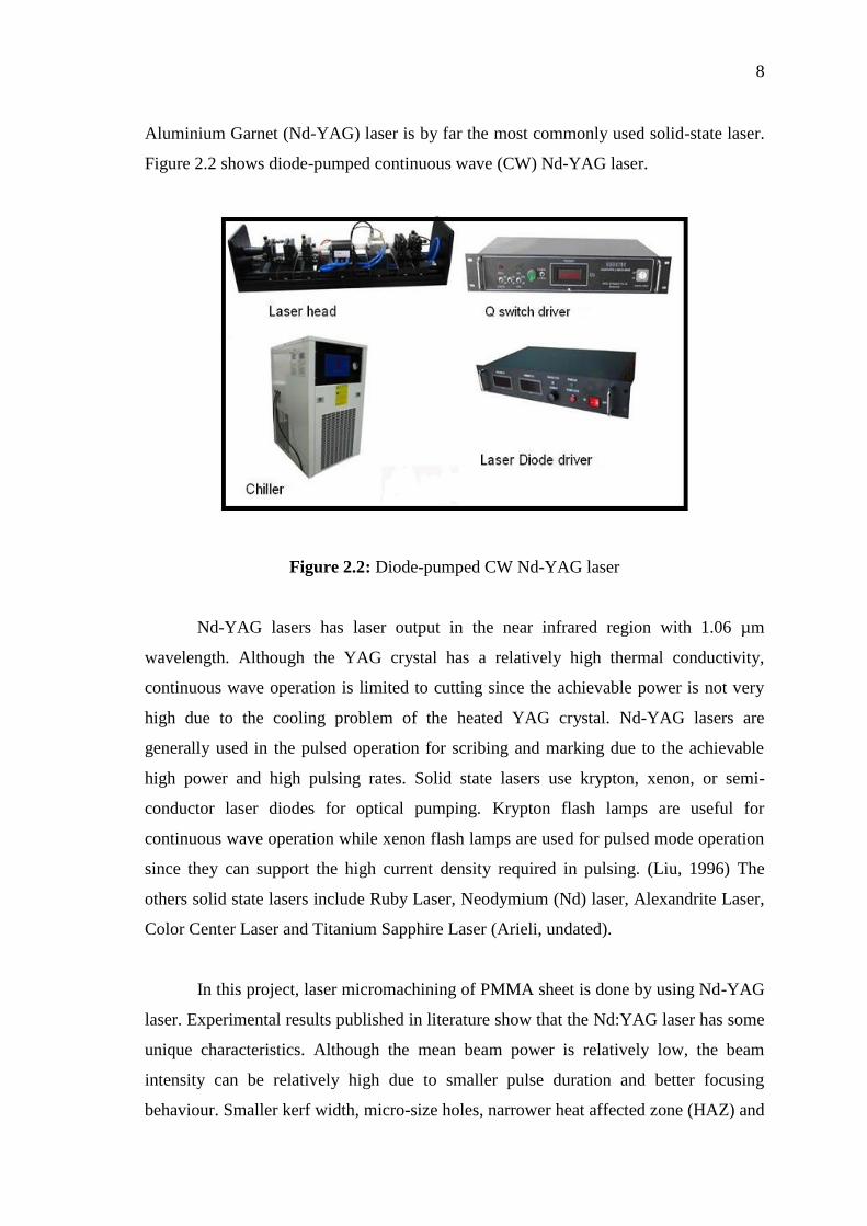
Aluminium Garnet (Nd-YAG) laser is by far the most commonly used solid-state laser.
Figure 2.2 shows diode-pumped continuous wave (CW) Nd-YAG laser.
Figure 2.2: Diode-pumped CW Nd-YAG laser
Nd-YAG lasers has laser output in the near infrared region with 1.06 µm
wavelength. Although the YAG crystal has a relatively high thermal conductivity,
continuous wave operation is limited to cutting since the achievable power is not very
high due to the cooling problem of the heated YAG crystal. Nd-YAG lasers are
generally used in the pulsed operation for scribing and marking due to the achievable
high power and high pulsing rates. Solid state lasers use krypton, xenon, or semi-
conductor laser diodes for optical pumping. Krypton flash lamps are useful for
continuous wave operation while xenon flash lamps are used for pulsed mode operation
since they can support the high current density required in pulsing. (Liu, 1996) The
others solid state lasers include Ruby Laser, Neodymium (Nd) laser, Alexandrite Laser,
Color Center Laser and Titanium Sapphire Laser (Arieli, undated).
In this project, laser micromachining of PMMA sheet is done by using Nd-YAG
laser. Experimental results published in literature show that the Nd:YAG laser has some
unique characteristics. Although the mean beam power is relatively low, the beam
intensity can be relatively high due to smaller pulse duration and better focusing
behaviour. Smaller kerf width, micro-size holes, narrower heat affected zone (HAZ) and

9
better cut edge kerf profile can be obtained in Nd:YAG laser beam machining. Due to
shorter wavelength, Nd:YAG laser is highly absorbed when falling even on a reflective
surface (Dubey and Yadava, 2008).
The enhanced transmission through plasma, wider choice of optical materials
and flexibility in handling with the advent of fibre optic beam delivery are also
interesting characteristics of the Nd:YAG laser (Norikazu et al., 1996). Thick materials
can be cut in pulsed mode operation which offers high peak power. The development of
short pulse lasers using diode-pumped (DP) and Q-switching techniques (for frequency
doubling and tripling) enables Nd:YAG lasers to be very useful tool in the field of
micromachining (Meijer, 2004). In recent years, pulsed Nd:YAG lasers are being
applied for precision cutting of thin sheets with narrow kerf, micro-drilling of holes and
intricate profile cut.
2.4.3 Liquid lasers
Liquid lasers are mainly dye lasers using large organic dye molecules as the
lasing medium. These dyes are capable of absorbing radiation from a wide range of
frequencies in the spectrum from which the lasing can occur. The lasers are tunable in
the sense that they can lase in the visible spectrum and parts of the infrared and ultra-
violet spectra. Therefore, they are desirable for spectroscopic and photochemical
applications (Liu, 1996).
Table 2.1 is listed common lasers with their wavelengths.
Table 2.1: Common lasers and their wavelengths
Laser type Wavelength (nanometers)
Argon Fluoride 193
Xenon Chloride 308 and 459
Xenon Fluoride 353 and 459
Helium Cadmium 325 - 442
Rhodamine 6G 450 - 650
Source: Aldrich (undated)