Embed Size (px)
Citation preview

COMPUTATIONAL MODELING OF DROPLET DEPOSITION AND COALESCENCE FOR DROP
WISE ADDITIVE MANUFACTURING
by
PRIYANSHU VISHNOI 7th August 2018
A thesis submitted to the faculty of the Graduate School of
the University at Buffalo, State University of New York in partial fulfilment of the requirements for the
degree of
Master of Science
Department of Chemical and Biological Engineering

DECLARATION
I hereby declare that the thesis is my original work and it has been written
by me in its entirety. I have duly acknowledged all the sources of
information which have been used in this thesis.
This thesis has also not been submitted for any degree in any university
previously.
Priyanshu Vishnoi 7th August, 2018
II

Acknowledgement
"The important thing in science is not so much to obtain new facts as to discover new
ways of thinking about them." These lines by Sir William Bragg always fascinates me
as a science student to keep working towards my goal. I keep in mind that the road to
my goals and targets is an arduous one, and only through perseverance will I be able
to accomplish them . This work could not have been completed without the constant
support and guidance of my professors, co-workers, family and friends .
First and foremost, I would like to thank my advisor, Dr. Edward P. Furlani , for his
supervision and giving me this wonderful opportunity to work under him on some of
the most exciting projects. His invaluable assistance and never-ending support, on
both technical and personal levels have always inspired me to keep going forward .
Had it not been for his invaluable constructive comments and suggestions, this work
would not have been completed . He was always patient with me during hard times
and the faith he showed in me was a huge motivation to keep working and deliver the
results in the best way possible. It was an honor to be a student of such a multi
talented personality, who was not only a great scientist but also a father figure for me.
He will be dearly missed .
My sincere thanks to my current advisor, Dr. Mike T. Swihart for taking me as his
student during the latter part of my degree His invaluable suggestions in improving
this work has made it look presentable. It was his guidance and constructive
comments because of which this work could be completed .
Special thanks to Dr. Haiqing Lin for serving as my committee member and devoting
his time towards my research .
Ill

I would like to express my profound gratitude to my group members and friends Viktor
Sukhotskiy, Aditi Verma, loannis Karampelas, Shruti Jose and Gourav Garg for their
constant guidance, active participation , lively discussions, and providing support and
feedback throughout my research.
Above all , my deepest gratitude and heartfelt thanks to my beloved parents, Dr.
Sanjay Vishnoi and Dr. Alka Vishnoi , and my loving sister Sonakshi Vishnoi , for their
everlasting love and motivation . Whatever I am today is because of the belief they had
in me and the support they provided . I shall forever be in their debt.
IV

Contents COMPUTATIONAL MODELING OF DROPLET DEPOSITION AND COALESCENCE FOR DROP-WISE ADDITIVE MANUFACTURING ...................................................................................... I
Acknowledgement .................................................................................................................................. 111
Abstract .....................................................................................................................................................VI
Chapter 1: Introduction ..........................................................................................................................1
Additive Manufacturing & 3D Printing ............................................................................................ 1
Magnetohydrodynamics.....................................................................................................................8
The Lorentz Force ..............................................................................................................................10
Chapter 2: Process Description and Computational Models ..................................................... 13
Process Description ..........................................................................................................................13
Introduction to the Computational Model .................................................................................... 16
Flow-3D Models and Parameters ................................................................................................... 19
a.) Solidification Model ............................................................................................................... 19
b.) Surface Tension Model ......................................................................................................... 21
c.) Viscosity and Turbulence .................................................................................................... 22
d.) Heat transfer Model ............................................................................................................... 24
Chapter 3: CFD Modeling .....................................................................................................................26
Boundary Conditions ........................................................................................................................27
Chapter4: Results and Discussion ....................................................................................................31
Single layer model .............................................................................................................................31
Effect of Droplet Overlap Fraction.................................................................................................32
Effect of Droplet Ejection Frequency............................................................................................36
Summary ..............................................................................................................................................43
Conclusion ...............................................................................................................................................44
Future Work Recommendations.........................................................................................................45
References ...............................................................................................................................................46
V

Abstract
Drop-on-demand additive manufacturing is a novel 3D printing technique. Additive
manufacturing (AM) is a bottom-up manufacturing process in which material is joined
or solidified under computer control to create a three-dimensional object. In this thesis,
we analyze an innovative additive manufacturing method that involves the drop-on
demand (DOD) printing of molten aluminum droplets to build three-dimensional (3D)
metal structures of arbitrary shape. Aluminum alloy Aluminum 6061 is used as the
metal in our study. This technique is based on magnetohydrodymanic (MHD) droplet
generation. In conventional three dimensional (3D) metal printing technique such as
Selective Laser Melting (SLM), Direct Laser Fabrication (DLF), Electron Beam Solid
Fabrication (EBSF) and related methods, an object is created by layer-by-layer
patterned deposition of heated material on a moving substrate. In MHD-base DOD
additive manufacturing of liquid metal , a metal spooled wire (approximately 1 mm
diameter) is fed into a ceramic reservoir where it is resistively heated to form molten
metal. The molten metal flows from the reservoir into an ejection chamber via capillary
forces. The assembly of ejection chamber and ejection reservoir is also known as the
printhead . The printhead is surrounded by a solenoid copper coil that is electrically
pulsed to produce a transient magnetic field (B) within it. The magnetic field , in turn
induces a circulating current density (J) , that back couples to the transient magnetic
field thereby generating a MHD Lorentz force density (fMHD) within the molten metal in
the ejection chamber, whose radial component creates a transient "effective pressure"
VI

(P) pulse that ejects a liquid metal droplet through the orifice. The metal droplet travels
through the argon-gas atmosphere and deposits on the object being fabricated. The
argon gas shroud is needed to prevent oxidation of liquid aluminum. We present an
analysis of a commercial MHD-based printing system under development by Vader
Systems (www.vadersystems.com ) and introduce a computational model that helps
to predict system performance. We discuss the underlying physics and the thermos
fluidic aspects of droplet deposition. We also demonstrate the use of Computational
Fluid Dynamics (CFO) to analyze the effects of various parameters on droplet
deposition, coalescence and solidification, and ultimately on the final printed structure.
A finite-volume thermo-fluidic analysis was performed using the commercially
available CFO software Flow-3D (www.flow3d.com). Computational simulations were
performed to understand and analyze the droplet-air and droplet-substrate
interactions, and to study the effects of various parameters on the final printed
structures. The presented models provide insight into the underlying mechanism
behind droplet deposition and droplet solidification on the surface. We also
demonstrate good agreement between our computational models and measured data.
VII

Chapter 1: Introduction
Additive Manufacturing & 3D Printing
Additive Manufacturing (AM), also referred to as 3D printing, involves manufacturing of a
3D structure in a sequential layer-by-layer fashion . Objects of almost any shape, size or
geometry can be fabricated based upon a digital model from a Computer-Aided Design
(CAD) file . In recent years, the demand for high-end customized metal parts has
increased multifold . Cost of production and product quality are two major factors when
considering a particular manufacturing technique. When developing a prototype, it is
important to consider different tools available and the various processes used for
producing different parts within a novel design . Prototype production can be broadly
categorized into two brackets: Additive manufacturing (3D printed parts) and Subtractive
Manufacturing (Casting methods or injection molding and Computer Numerical Controlled
(CNC) machined parts) . Subtractive manufacturing is the most commercially available
technology for fabrication of metal parts. It can typically be divided into casting methods
and CNC machined parts, which are fully developed but limited . Casting is a
manufacturing process in which metal , in its liquefied form, is poured into a hollow cavity
of desired shape (known as mold) and then allowed to solidify. The solidified metal takes
the shape of mold and is then ejected out of it. On the other hand, CNC machining makes
use of cutting tools to eliminate material from a block of a pre-existing part. Conventional
technologies make use of drills, lathes and milling machines to execute the process.
Subtractive manufacturing is especially appropriate for large objects or mass production.
Additive manufacturing, on the other hand, is a process in which 3D objects are fabricated
1

by successive deposition of material in layers, whether the material is polymer, plastic,
metal, concrete etc., such that it takes a predesigned shape. 3D printing has always been
advantageous for rapid prototype development, but in recent times it has started to make
its impact on the manufacturing world as well. It is especially useful for rapid prototyping
of metallic structures that are problematic or too costly for the conventional methods.
More recently, AM is being used to manufacture end-use products in aircraft, dental
restorations, medical implants, automobiles, and even fashion products.
Additive manufacturing can be used to fabricate highly complex structures that can still
be extremely light and stable. It has been in practice for more than 15 years . The term
AM encompasses many technologies including subsets like 3D printing, Rapid
Prototyping (RP), Direct Digital Manufacturing (DOM), layered manufacturing and additive
fabrication. An area of particular and intense interest is AM of metal objects. Conventional
metal AM technologies make use of lasers or electron-beams (EBs) as directed energy
sources to fuse together specially prepared metal powder. Laser-based AM techniques
include Direct Metal Laser Sintering (DMLS), Selective Laser Sintering (SLS) and Laser
Solid Forming (LSF). The EB technologies include Electron Beam Melting (EBM), in which
an EB is used to selectively melt the layer of metal in its powdered form . However, these
processes have drawbacks including both production costs and complex process control,
which are due to the energy-intensive equipment needed to convert metal into powder
form prior to fabrication, and the precise melting and fusing of the powder to form a
desired 3D structure. Fused Deposition Modeling (FDM) is another AM technology that
2

can print 3D structures using both metals and thermoplastics as feed material. Table 1
describes various AM technologies developed over the years .
Table 1: AM technologies classified according to their type and describing the materials that can be used as feed input.
Type Technologies
Extrusion Fused Deposition Modeling (FDM)
Wire Electron Beam Freeform Fabrication
Granular Direct Laser Sintering (DLS)
Electron Beam Melting (EBM)
Selective Heat Sintering (SHS)
Selective Laser Sintering (SLS)
Powder bed and inkjet head 3D printing, Plaster-based 3D printing
Laminated Laminated object manufacturing (LOM)
Light Curing Stereolithography (SLA)
Direct light processing (DLP)
Drop-on-Demand Magnetojet Piston-based ejection
Pneumatic-based ejection An a1ternate .5U p nnun g tecnrnque urn1zes IIqu1a metal to aaamve1
Materials
Thermoplastics, Eutectic Metals, Edible Materials Almost any metal alloy Almost any metal alloy Titanium alloys
Thermoplastic powder
Thermoplastics, metals/ ceramic powder Plaster, Metals, Ceramic powder
Paper, metal foil , plastic film Photopolymer
Photopolymer
Aluminum alloys Tin Electrical Solder y manuracture metal
objects. This process, generally referred to as "material jetting" uses droplet generators
and molten droplets in the nano- and pico-liter range and can be implemented in two
distinct modes: continuous jet and drop-on-demand . It is analogous to inkjet printing and
offers rapid manufacturing of parts directly from computer models by sequential printing
3

of two dimensional layers. Conventional inkjet technology has been used to print a variety
of functional media and devices by depositing and patterning materials that range from
polymers to living cells. Molten metal printing can be used directly to print cores and shells
thus eliminating initial tooling cost. In the continuous jet method, a liquid metal jet is
formed and caused to break up via a perturbation stimulus into a continuous stream of
well-defined droplets (volume and velocity) at a fixed distance from the nozzle. The
droplets needed for fabrication are deposited on the build substrate, the other droplets
are deflected . In contrast, in the drop-on-demand method, well-defined droplets are
ejected from a nozzle and deposited on a build substrate as needed. The precision of the
DOD jetting process enables a reduction in material waste, and thus reduction in cost and
increase in efficiency. Figure 2 shows various continuous and DOD ejection systems.
Additive manufacturing can be applied to print 3D structures of various substances such
as ceramics, metals, metal composites and polymers. In recent times, direct printing of
metals based on droplet ejection techniques has been a subject of research . Still ,
challenges remain in realizing the optimum operating parameters of operation that include
the following :
i) Thermal management: The droplet generator (printhead) has to operate at a
temperature above the melting point of the metal being printed. At such high
temperatures, there is a possibility of thermal damage and degradation to the printhead
assembly and hence, an efficient cooling system is a primary requirement. Also, this limits
the number of metals that can be used as feed and the thermal gradients might induce
mechanical stresses that are undesirable and affect the strength of the solidified structure.
4

ii) Droplet ejection: Droplet ejection control is the most important process parameter when
it comes to process throughput. Several factors contribute to the stable droplet ejection
such as high contact angle and surface tension of the metals, the capillary priming of
nozzles, maintaining the axial stability of ejected droplets and selectively varying the
droplet size, if required .
5

Continous Jetting Method
Screw Piston Pneumatic
Drop on Demand Method
~ j l Piezoele•ctric MagnetojetThermal
I Vapor Bubble
Piezoelectric Electromagnetic Coi lHeater Actuator
Figure 1:Continuous vs Drop-on-demand jetting methods
iii) Droplet patterning (deposition , coalescence and solidification): Droplet patterning
controls the shape and strength of the 3D structure. Droplets need to deposit smoothly
on the moving substrate. Oxidation of metal droplets need to be avoided as it affects the
resolution of 3D solid structures and also interferes with the droplet coalescence. Thermal
gradients need to be controlled between droplet-atmosphere and droplet-substrate
surface to ensure proper droplet coalescence and solidification .
6

The focus of this work is on drop-on-demand metal printing in which droplets of metal are
ejected through the orifice at a regular, desired interval in order to form 3D structures on
the substrate. Drop-on-demand 3D printers are commonly made up of a small-sized
orifice, a reservoir and a printhead that generates a pressure pulse so as to create a
discontinuity in the ejected fluid stream. The source of actuation of pressure pulse could
be thermal , piezoelectric or electromagnetic (as shown in Figure 2). In order to build
accurate droplet patterning, a substrate is set up beneath the printhead . The substrate
moves at a pre-programmed velocity, which must be matched to the frequency of the
droplet ejection . Droplet ejection frequency varies according to the shape of the structure
to be printed . In this work we provide an overview of a novel DOD metal AM technique
based on magnetohydropdynamic (MHD) droplet ejection that can be used to create 3D
structures with complex geometries. We also demonstrate a computational model that is
used to predict system performance and explore critical performance parameters. The
MHD-based printing system is under development by Vader Systems
(www.vadersystems.com) under the tradename Magnetojet™. The underlying physics of
droplet generation and the thermos-fluidic aspects of droplet deposition , coalescence and
solidification are described in the following sections. The operating principle of this
process is based on MHD, which exploits a Lorentz Force acting on induced currents
within the conducting molten metal as a droplet ejection mechanism. The ejected droplets
impact the moving substrate where they coalesce, cool and solidify to form extended solid
structures. Solid structures of arbitrary shape and size can be fabricated in a layer-by
layer fashion with the help of this technology. In this thesis, we describe the Magnetojet™
process, introduce a computational model that can guide process design , and discuss
7

key technological challenges. Sample 3D structures printed by Magnetojet™ are also
included in this thesis .
Magnetohydrodynamics
The Magnetojet™ process is based on the fundamentals of magnetohydrodynamiics
(MHD). MHD, as the name suggests is the study of application of electromagnetic field
forces to electrically conducting fluids such as liquid metals, plasmas, salt water, and
electrolytes. The field of MHD was introduced in 1907. The fundamental concept behind
MHD is that magnetic fields can induce currents in a moving conducting fluid, which in
turn polarizes the fluid and reciprocally changes the magnetic field itself. MHD has a wide
range of applications in fields including geophysics, astrophysics, sensors, magnetic drug
targeting, power generation . It is widely used in continuous casting of metals.
MHD spans two branches of physics, classical fluid dynamics and electromagnetics. The
governing equations of MHD for Newtonian fluid include the Navier-Stokes equation,
mass continuity and Maxwell equation . The differential forms of these equations are:
8p 2u-+pu.Vu=-Vp+µV u+ fMHD (1)
8t
<5p +V.(pu) = 0 (2)8t
fMHn =J x B+pE (3)
8BVxE=-- (4)8t
8

(5)
J=o-E+o-uxB (6)
In addition to the above relations, we have
v'-B=O (7)
v'-J=O (8)
Where u = fluid velocity, p = fluid density, p = fluid pressure, J = current density, µ1 =
fluid dynamic viscosity, B = Magnetic flux density, o- = electrical conductivity. The MHD
body force density (N/m3) is defined in equation (3) .
In this DOD process, a spooled metal wire, approximately 1 mm in diameter, is
continuously fed to a ceramic reservoir of the nozzle where it is resistively heated to form
3 ml of molten aluminum. The molten metal flows from the reservoir into a nozzle via
capillary forces . The nozzle is surrounded by a copper coil that is electrically pulsed to
produce a transient magnetic field B within it. The magnetic field, in turn, induces a
circulating current density J, that back couples to the transient magnetic field thereby
generating a magnetohydrodynamic Lorentz force density ( / MHD) within the ejection
chamber, whose radial component creates a transient "effective pressure" pulse that
9

ejects a liquid metal droplet through the orifice. Figure 3 and Figure 4 give a detailed view
of actuation using the MHD principle and Lorentz force.
The Lorentz Force
Figure 2:Conceptua/ schematic of MHD jetting process.
A point charge in the presence of electromagnetic fields experiences a combination of
electrical and magnetic force. Charges move in the magnetic field and encounter
"Lorentz" force, named after Dutch physicist Hendrick Lorentz, that is perpendicular to
both their velocity and the induced magnetic field :
Fq=q(vxB) (9)
10

z
Electrode
Voltage
Figure 3:Schematic diagram of actuation of MHD with Lorentz force as the driving force.
The charged particle gains energy from an electric field, but not from a magnetic field .
This is because the magnetic force is always perpendicular to the particle's motion, and
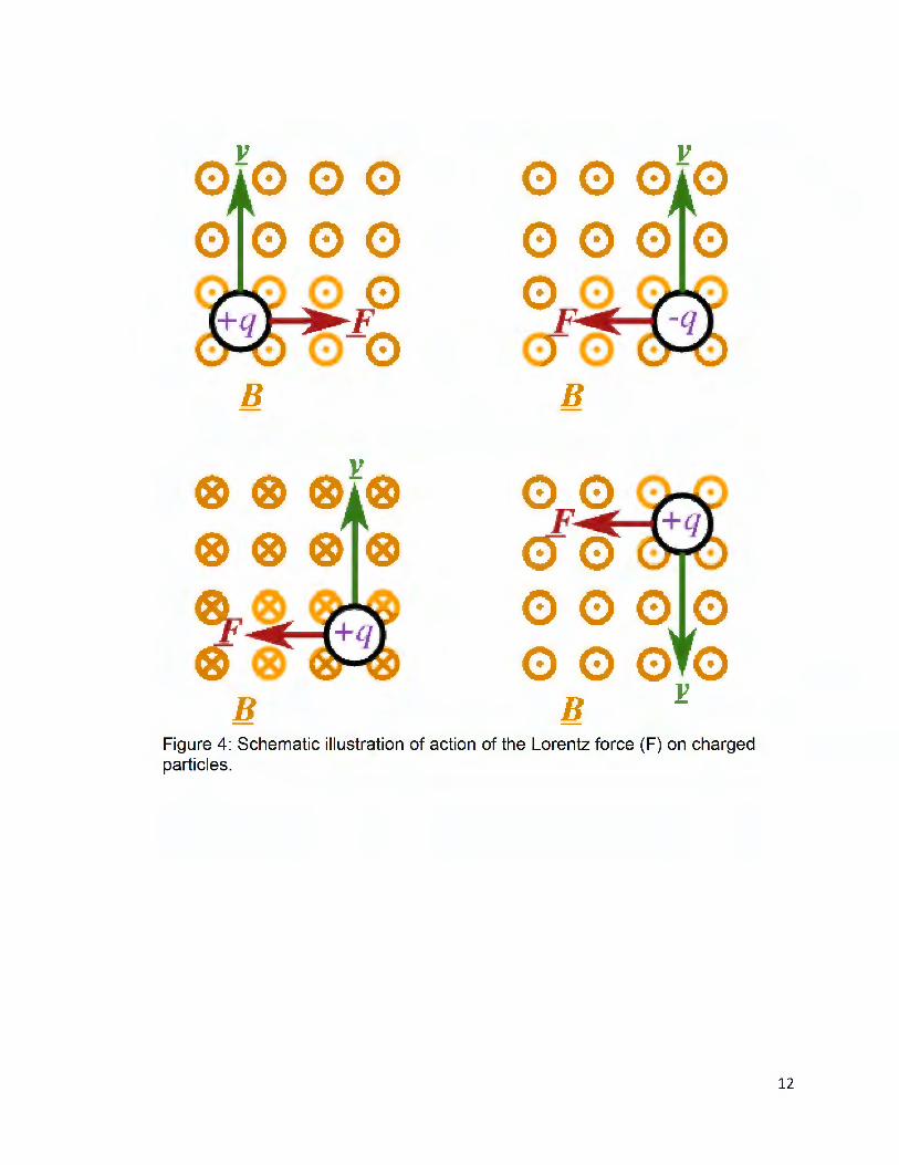
hence, does no work on it. Figure 5 shows the description of Lorentz force on the charged
particles. The positive and negative charges experience Lorentz forces in opposite
directions (though both perpendicular to the current flow) . The velocity and pressure of a
conducting liquid metal can be altered by the Lorentz force . The Lorentz force is used in
many devices including mass spectrometers, velocity filters, cyclotrons and other circular
path accelerators, magnetrons, electrical generators, and loudspeakers.
11
• •
· -V
· 0 0 00 ·0
I!!!!!!!!!!!!!! F ------ . . B
B
0 0 · -V
· 00
B
0· ---I
C:-r· 00 0 0 ·
V ·
B Figure 4: Schematic illustration of action of the Lorentz force (F) on charged particles.
12

Chapter 2: Process Description and Computational Models
Process Description
The Magnetojet™ printing process has been used to create aluminum parts with a
repetition rate up to 1000 droplets/sec, with a droplet placement resolution of 500 µm.
It has achieved a mass deposition rate of up to 1 lb per hour based on a single orifice
that generates droplets with a 500 µm diameter. In addition , it is a relatively low cost
process that can print parts with improved mechanical properties owing to the
presence of a unique metal grain structure. In this chapter, we describe the
fundamental principles of Magnetojet™ printing and introduce computational models
that that predict droplet deposition, coalescence and solidification and can be used to
optimize the process. Sample 3D structures printed by Magnetojet™ are also
demonstrated in this presentation .
13

Argon Gas "- AluminumShroud
Wire Spool
Pulsed Input Molten Metal
t Voltage into
Coil Windings
ov --l-+-l---0 ■ B'! ■■■ ■ a ■
IJ ~GI ■■■ lllHI ll Bl!l ■■■ IU!ll
• ·
•· ·
· · ■■ ll !iF' ■■■ ■■ II
11 ■ 1 ••• ■■ a ~·,
Heated Substrate
••••••
I Computer Controlled
Motion System
I
Figure 5:Schematic design of the MHD-based DOD liquid metal printing system
Vader Systems have developed and commercialized a prototype printing system with
a printhead consisting of a two-part refractory nozzle, a water-cooled solenoid coil and
an argon gas shroud. Aluminum wire enters the reservoir from the open end on the
top from a wire feeder system consisting of a wire spool, feed rollers and a servo motor
connected via a gearbox. Liquefaction of aluminum wire takes place at 1123-1223 K
(850-950°C) by resistively heating the cylindrical titanium dioride refractory reservoir.
As new metal enters the reservoir, it is melted by thermal conduction from the already
melted molten metal and the refractory nozzle . MagnetoJet follows the
14

electromagnetic droplet ejection mechanism. A short voltage pulse is applied to the
coil , which can be divided into positive and negative pressure events. During the
positive cycle, positive voltage is applied to the electromagnetic coil. This positive
voltage leads to linearly increasing electric current within the coil that induces linearly
increasing axial magnetic flux density through the nozzle. Because of the increasing
magnetic field , clockwise (top view) circulating eddy currents are induced within the
liquefied metal thus creating an inward directed Lorentz force density within the nozzle
that can be thought of as an effective pseudo pressure that acts to eject a droplet.
During the negative cycle : complementary events happen . Negative voltage is applied
to the electromagnetic coil leading to linearly decreasing electric current which is cut
off when it reaches zero. The linearly decreasing electric current induces linearly
decreasing magnetic flux density. As a result of this, counter-clockwise circulating
eddy current are generated in the liquefied metal thus creating an outward directed
Lorentz force density, which can be considered as an effective negative pseudo
pressure. The coupling between the magnetic field and the electric current results in
a Lorentz force that provides a pseudo-pressure for jetting the molten metal onto a
build platform. The lower part of the nozzle contains an orifice, ranging from 100-500
µm in diameter, through which liquid metal droplets are ejected . The metal droplet
travels through an argon shroud , which envelops the reservoir and the orifice, and is
deposited on a stainless steel substrate that is heated to a temperature below the
melting point of the deposited metal. The droplets coalesce and solidify on the
substrate to produce extended solid structures through layer-by-layer deposition,
which is achieved by moving the substrate using computer numerical control (CNC)
15

and computer aided design (CAD) file. Figure 6 depicts a cross sectional view of the
printhead and other essential components of the MagnetoJet process. The size of
droplets varies from 50-550 µm in diameter, depending on the orifice geometry,
diameter, ejection frequency and pulse duration . Steady droplet ejection rates ranging
from 40-1000 Hz with short burst ups up to 5000 Hz have been achieved with the
machine prototype. Common aluminum alloys such as 4043, 6061 and 7075 have
been used to successfully print solid metal structures.
Introduction to the Computational Model
Computational simulations were performed prior to prototype fabrication and during
the design cycle to optimize selected process parameters for performance. The focus
of this study is on droplet-air interaction and droplet-substrate interaction .
Computational Fluid Dynamics (CFO) analyses were performed using the
multiphysics Flow-3D (www.flow3d .com) software to study the thermo-fluidic aspects
of droplet deposition , coalescence and solidification . Solidification of droplets on the
substrate is influenced by various factors such as droplet ejection frequency, droplet
temperature, velocity, size, center-to-center droplet spacing, substrate and
surrounding temperature and others.
Aluminum alloy 6061 is used in running simulations and machine tests . Aluminum
6061 consists of magnesium and silicon as the alloying elements. 6061 is the most
common alloy used for aluminum extrusion. The significant properties of aluminum
6061 used in the simulations are: solidus temperature = 847 K, liquidus temperature
= 905 K, specific heat = 1.176 J/g/K, Latent Heat of Fusion = 397 .5 J/g, Surface
16

Tension Coefficient = 870 g/s2. Density, viscosity and thermal conductivity are used
as a function of temperature . Contact angle between aluminum droplet and substrate
is taken as 70°. Spherical droplets of aluminum at 1023 K impact a stainless steel
substrate, kept at 473 K, from a height of 3 mm. oxidation of molten aluminum takes
place in the presence of oxygen, leading to the formation of Al203 oxide skin .
Formation of oxide could impede the ejection of metal droplets, as well as reduce the
quality of the printed object. In order to prevent metal oxidation , an inert environment
is maintained around the nozzle with the help of argon gas shroud . In order to fabricate
precise 3D metal solid structures, droplet patterning, coalescence and solidification
are critical. In this process, droplets are ejected with a velocity ranging from 1-10 m/s
and travel through the argon-shielded atmosphere before impacting the substrate
surface. Thermal diffusion from the droplet to the surrounding atmosphere takes place
during flight and after impacting the substrate surface, droplet solidification takes place
owing to the thermal diffusion from droplet to substrate, and from continued heat
transfer from droplet to air. The substrate is heated to a temperature that is below the
melting point of the metal. This reduces the temperature gradient between droplet and
substrate and hence, slows down the rate of thermal diffusion . This promotes
smoother coalescence with the neighboring droplets (intralayer) and between layers
(interlayer) as well as the growth of favorable metal microstructures, thus creating 3D
solid structures with low porosity and no undesired layering artifacts. In the droplet
deposition model , we designed CFO models to investigate the droplet deposition,
coalescence and solidification on a heated substrate. A Finite Volume thermo-fluidic
analysis was performed using the solidification model in Flow-3D. These models solve
17
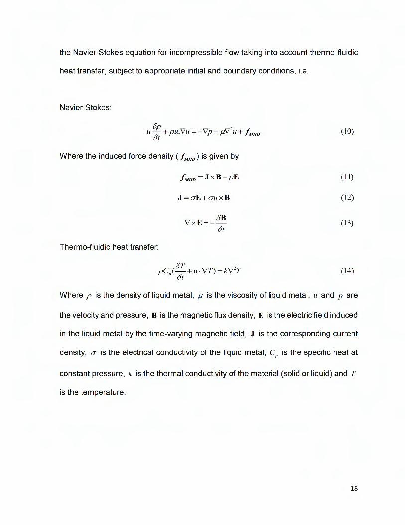
the Navier-Stokes equation for incompressible flow taking into account thermo-fluidic
heat transfer, subject to appropriate initial and boundary conditions, i.e.
Navier-Stokes:
8p 2 u- + pu.Vu = -Vp + µV u + fMHD (10)
8t
Where the induced force density ( / MHn) is given by
fMHD =JxB+pE (11)
J =o-E+o-u x B (12)
8BVxE=- (13)&
Thermo-fluidic heat transfer:
8TpC (-+u-VT)=kv' 2T (14)
p 8t
Where p is the density of liquid metal, µ is the viscosity of liquid metal, u and p are
the velocity and pressure, B is the magnetic flux density, E is the electric field induced
in the liquid metal by the time-varying magnetic field , J is the corresponding current
density, O" is the electrical conductivity of the liquid metal, Cp is the specific heat at
constant pressure, k is the thermal conductivity of the material (solid or liquid) and T
is the temperature .
18
Flow-3D Models and Parameters
a.) Solidification Model
The solidification model simulates the effects of solid-liquid phase change. This model
does not take into account crystalline structures or formation of grain boundaries but
rather models the fluid to solid phase change as a continuum. Flow-3D investigates
the molten metal liquid to solid phase change as it impacts the heated substrate. The
solidification model is used in concurrence with the heat transfer model. The latent
heat is released linearly as the material cools from the liquidus to solidus temperature.
The rigidity can be modeled based on the coherency point which refers to the state of
a solidifying alloy at which a coherent dendrite network is established during the grain
formation and the alloy starts to develop additional mechanical resistance because of
this . Effects of solidification model are accounted for in one of the two ways: either by
using enhanced viscosity of solidified fluid or through use of a drag force .
The viscosity-based model is applied when the solidified phase is deformable and can
still move. The viscosity of the partially solidified metal depends on the solid fraction .
The viscosity varies linearly with the solid fraction. A constant finite viscosity, higher
than that of the liquid phase, is assigned to the solidified fluid . The viscosity of the
liquid/solid mixture is calculated as a solid-fraction weighted average of the viscosities
of the liquid and solidified phase. When the solid fraction is zero, the model takes the
viscosity of the liquid and when the solid fraction is one, the viscosity is equal to a user
specified viscosity.
The drag-based flow model is built upon the porous media drag concept. By neglecting
the volume change associated with a phase change and assuming that solid material
19

is at rest with respect to the computational mesh, we can approximate the solidification
process (i.e . state of zero flow velocity) by using a drag coefficient that is a function of
the local solid fraction. Solidification implies a rigidity and resistance to the flow. This
rigidity is dependent upon the coherent solid fraction . For low solid fractions, i.e. below
point of coherency, the viscosity is a function of solid fraction . For solid fraction larger
than the coherent solid fraction , a Darcy type drag force with a drag coefficient
proportional to the function of solid fraction is used . If the solid fraction exceeds the
point of rigidity, the critical solid fraction , the drag becomes infinite and there can be
no flow with respect to the computational grid.
In this work, we use the porous media drag based solidification model with no
shrinkage. The critical solid fraction value was taken to be 0.67. Release of the latent
heat of fusion was linear with temperature . The liquidus temperature was specified at
905 Kand the solidus temperature at 847 K.
Because density is also a function of temperature, the temperature dependent values
were used, as shown in Figure 6.
20

Density vs Temperature for Aluminum 6061
2.41
2.4
2.39
2.38
2.37
2.36
2.35
2.34
2.33
2.32
2.31
900 950 1000 1050 1100 1150 1200
Figure 6: Variation ofDensity (in gm/cm3} vs Temperature (in K) for Aluminum 6061
b.) Surface Tension Model
Surface tension force acts in a plane tangent to any sharp interface. The interface can
be between a gas and liquid or between two immiscible liquids. The force occurs
because of the differences in the inter-molecular forces between the two materials. In
Flow-3D, we model surface tension with a free surface or sharp interface between two
fluids . The activation of surface tension model requires the user to set a surface
tension coefficient at the interface and contact angle at the point of contact of the fluid
fluid interface and the solid surface. The contact angle controls the wetting behavior
where the interface meets solid wall boundaries and solid components. Wetting of
liquids can be divided into two classes: reactive and non-reactive. In our case, reactive
wetting takes place as aluminum rapidly reacts with many of the common elements
21

found in refractory ceramics to form oxides and other compounds. But since reactive
wetting complicates the fluidic analysis greatly, it is ignored in this surface tension
model. The contact angle (Sc), measured through the liquid, is defined as the angle
between the tangent at the point where liquid-vapor interface meets the solid surface,
and the solid surface. The contact angle can take values between 0.0 (complete
wetting) and 180° (completely non-wetting). Surface tension coefficient (cr) can be a
constant or a function of temperature . The temperature dependent relationship of
surface tension coefficient is given by:
(15)
Where a is the computed surface tension coefficient, cro is the user-defined value of
surface tension coefficient, da- is the temperature-dependence of surface tension dt
coefficient, T is the local temperature, and T * is the user-defined reference
temperature. For aluminum 6061 used in our model, a-0 = 870 g/s2 , da- = 0.152 g/s2/Kdt
and T* = 953 K.
c.) Viscosity and Turbulence
Viscosity is a fluid property that arises from intermolecular forces and manifests as a
resistance to flow. Fluid viscosity is a key parameter in the Navier-Stokes equations.
When modeling confined flows, it is important to define the slip conditions at the fluid
solid interface. Slip conditions describe the fluid velocity near and in contact with the
material boundary (wall). There are generally three types of slip conditions in CFO: no
22

slip, partial slip and free slip . A free slip condition is one in which the surface offers no
resistance to the flow and the fluid velocity profile is unchanged . This condition is often
used to describe a boundary between two fluids . Partial slip conditions offer some
resistance to the fluid flow and there is a partial reduction in fluid velocity at the
boundary. The no-slip condition is one in which the fluid velocity is zero at the
fluid/solid interface.
In a partial-slip boundary condition , the slip velocity at the boundary is directly
proportional to the shear stress, and the friction coefficient is the parameter that is
used as a constant of proportionality and can be applied to both solid components and
solid/liquid interface. As the friction coefficient approaches infinity, the slip velocity
approaches zero (no slip condition) . A positive, finite friction coefficient corresponds
to the partial slip condition . In Flow-3D the static friction coefficient is set to -1.0 , so all
unspecified components have no-slip condition by default. In this analysis, we assume
flow is laminar and viscosity is used as a function of temperature, as shown in Figure
7.
23

Viscosity vs Temperature for Molten Aluminum
6061 0.041
0.039
0.037
0.035
0.033
0 .031
0 .029
0 .027
0 .025
0 .023
840 890 940 990 1040 1090
Figure 7: Variation of viscosity (in gm/emfs) vs temperature (in K) for Aluminum 6061
d.) Heat transfer Model
Flow-3D's heat transfer model is used to study the thermal behavior of the printing
process. The heat transfer model solves full conjugate heat transfer equations, taking
into account the heat transfer between fluid , solid , and ambient air regions (referred
as void) through conduction , convection , and radiation . It computes the dynamic
surface temperature of the deposited layer. This model predicts the heat transfer that
takes place during the droplet's flight to the substrate and the cooling of the droplet
once it impacts the substrate surface. We have used the first-order fluid advection
option in conjunction with fluid to solid heat transfer, which is efficient and robust for
most heat transfer problems. There are four different types of heat transfer models
that can be defined for the substrate in the geometry specifications: (a) Full heat
24

transfer (b) Dynamic uniform temperature (c) Prescribed uniform temperature and (d)
Static temperature. Dynamic uniform temperature, prescribed uniform temperature
and static temperature do not solve for conduction and hence, we have used the full
heat transfer mode to account for conduction in the component. The general equation
solved for dynamic structure temperature is:
5T 5[Kw(l-AJ ~ w] (1-V )p C _ w - X
F w w <)[ <)X (16)
5[K (1- A )R <5Tw] 5[K (1 - A ) <5Tw] w Y 5y w z 5z -
···R--------------T6y <)z SOR
Where Tw = solid structure temperature, Pw = Solid material density, Cw= Solid specific
heat, K w= Solid thermal conductivity, T80 R =Specific energy source term composed of
contributions from specified external sources and solid-liquid heat transfer.
Fluid calculations are performed with the energy transport equation for heat transfer
between fluid and substrate surface. Flow-3D calculates heat transfer from the
boundaries having known temperatures. The surface temperature of the substrate is
specified and the local energy source rate is calculated as:
(17)
Where h = heat transfer coefficient for solid/fluid heat transfer, WA= surface area of
the substrate in contact with the fluid , Tw = structure surface temperature, T = fluid
surface temperature.
The fluid transfers heat to the void according to :
(18)
25

Where hv = heat transfer coefficient for fluid/void heat transfer, Wv = heat transfer
surface area, Tv = void temperature, T = fluid temperature .
Chapter 3: CFD Modeling
This chapter describes the Flow-3D CFO model that describes droplet deposition,
coalescence and solidification on a heated substrate. A droplet is initiated above the
substrate to simulate the conditions of droplet's flight in the air and its subsequent
impact and solidification on the substrate. A number of droplets are printed , first in a
straight line and then extending the model to print layered structures with one layer on
top of the other to examine the droplet interaction with the neighboring droplets
(intralayer) and between layers (interlayer). Later, this model was further extended to
build inclined structures, with angle of inclination between the structure and the
substrate varying from 45° to 90°. A number of variables effect the quality of print
structures, including :
1. Initial temperature of the droplet.
2. Initial temperature of the substrate.
3. Z-direction velocity of the droplet with which it travels in the air.
4. Ejection frequency of the droplets.
5. Droplet Overlap Fraction , which is defined as the ratio of maximum overlap length
between any two droplets to the outside diameter of either droplet.
A finite volume thermo-fluidic analysis was performed using the solidification model in
Flow-3D. Flow-3D employs the Volume of Fluid (VOF) approach to track the interface
between two fluids, which in this case is liquid aluminum and air. It evaluates the fluid
26
flow variables throughout the computational domain at each time step using the
Navier-Stokes equation . The temperature-dependent physical properties of molten
aluminum 6061 , such as density, viscosity, heat capacity and thermal conductivity
used as input in the model.
Boundary Conditions
The following boundary conditions have been used in our analysis :
Wall Boundary: The wall boundary condition applies a no-slip condition at the
boundary, as well as no velocity normal to the boundary. Hence, the fluid in contact
with the solid surface has zero velocity relative to the solid . The wall boundary
condition , in this case, is applied at the substrate surface.
Pressure Boundary: In a pressure boundary condition , we specify the pressure at
the boundary. There are two types of pressure boundary conditions that can be
applied in Flow-3D: static pressure and stagnation pressure. In a static pressure
condition , the pressure across the boundary is considered to be continuous and the
velocity at the boundary is assigned a value based on zero normal-derivative
conditions across the boundary. On the other hand, the stagnation pressure boundary
condition assumes stagnant conditions outside the boundary, i.e. the fluid velocity
upstream from the boundary is zero. The static pressure boundary condition is less
specific than the stagnation pressure boundary condition since it says nothing about
the fluid velocity outside the boundary (other than it is supposed to be the same as
the velocity at the boundary). Hence, stagnation pressure boundary condition is used
for all the simulations.
27

We have modeled droplet deposition , coalescence and solidification on a heated
substrate as a function of droplet ejection frequency and center-to-center spacing
between the droplets. In these models, spherical droplets of aluminum having a
diameter of 450 µm, travelling with a z-direction velocity of 2.5 m/s impact a heated
stainless steel substrate from a height of 3 mm. The initial temperature of droplet is
1023 Kand that of substrate is 473 k. the droplets is our models are modeled using
the Droplet Source Model of Flow-3D which generates a sequence of molten
aluminum droplets at specified time periods, in the atmosphere above the substrate.
Droplet source model allows us to model droplets at specific locations, velocities and
rate of generation , with varying size and initial temperature. In this work, we have
designed various structures using molten aluminum droplets, ranging from 10 to 30 in
number. The morphology of inclined pillars was studied as a function of droplet overlap
fraction . When building pillar structures using drop-on-demand process, control of the
droplet overlap fraction is critical. This variable is controlled by the relative velocities
of the droplet and the moving substrate during experiments, and via x-coordinate
placement of the droplet in the model. The droplets are generated at fixed x, y and z
coordinates defined by the user.
The droplets defined in our simulation have the same y and z coordinates, but different
x coordinates so as to vary the droplet separation and hence the droplet overlap
fraction so as to fabricate different structures, including inclined structures or layer-by
layer structures. The droplets are generated at a fixed rate (frequency) defined by the
time interval between consecutive droplets. The droplets are assigned zero velocity in
28
the x and y directions and a velocity ranging from 2-3 mis in negative z direction . The
thermal properties of the stainless steel substrate are:
Heat transfer coefficient to the atmosphere = 2000 erg/s/cm2/K
Thermal conductivity of the substrate = 7 .54 x 106 erg/s/cm/K
Density x Specific Heat= 3.78547 x 10⁷ dyne/cm2/K
The substrate temperature in our simulations is set at 473 K, which of course can be
varied to study its effect on droplet coalescence and solidification . Figure 9 describes
the computational domain , complete with initial droplet, void pointer and the substrate.
In Flow-3D, pointers have been used to define the extent and properties of regions of
fluid or void for all contiguous cells . Void pointers only require the specification of a
location and the properties. All open volume in contact with the specified location is
then assigned the properties associated with the pointer. Void pointers can also be
used to specify the heat transfer type, identifying unique void regions to which a certain
set of heat transfer coefficients are applied. Void parameters can also be used to
define not only the initial state of a void region but also its pressure and temperature
during the simulation by using a tabular definition of these parameters vs time.
Because our void pointer corresponds to atmospheric conditions, these features are
not exploited . The pointer is initialized with the temperature of 300 K and 1
atmosphere, and allows heat transfer with the environment during droplet's flight from
the orifice to the substrate. The following boundary conditions have been set in our
simulation :
X minimum : Specified pressure
X maximum: Specified pressure
29

Y minimum: Specified pressure
Y maximum: Specified pressure
Z minimum: Wall
Z maximum: Specified pressure
I I I
- Droplet-• • -. Void Poi ,
. Computa ional-Mesh pl1anes
. Substrate
Figure 8: Flow-3D computational domain showing droplet initialization, void pointer and
substrate.
30

Chapter4: Results and Discussion
In this chapter, we discuss the results of our simulation runs and analyze, in detail , the
effects of various parameters such as droplet ejection frequency, overlap fraction , and
droplet and substrate initial temperature. High resolution images are generated with
Flow-3D to effectively communicate the findings of our simulation runs . We started
with a very basic model in which 10 droplets were printed in a straight line and then
went on to simulate printing of more complex structures.
Single layer model
Ten droplets were modeled in a straight line. The droplets have a diameter of 250 µm
and a flight velocity of 5 mis. The initial temperature of droplets was 973 Kand that of
the substrate is 673 K. The ejection frequency of droplets is 100 Hz. The material
temperature
677.968
677.037
676.107
675.176
674.245
673.315
672.384
Figure 9: Temperature distribution of the solidified single layer structure.
31
properties of molten aluminum and stainless steel substrate are provided to the model.
Overlap fraction in this case is taken as 0.02, so that there is a small overlap, and
hence slight re-melting of the already deposited droplet takes place as a new droplet
impacts the substrate. Figure 10 shows the morphology and temperature distribution
of the deposited layer at the end of the simulation , at a point where they have nearly
reached the substrate temperature.
This basic model was further modified to print more complex structures. A three
layered structure was printed with 5 droplets in a single layer. Three layers were
printed at various droplet ejection frequencies to analyze the effect of ejection
frequency on the printed structure. Various parameters, such as droplet diameter,
flight velocity, initial droplet and substrate temperature, were changed to match the
parameters that are used by Vader Systems in their experiments. Next, inclined
structures were modeled to study their morphology as a function of droplet overlap
fraction. Overlap fraction was varied from 0.5 to 1.0 at a fixed droplet ejection
frequency for this analysis . In order to study the effect of ejection frequency on the
inclined structure, simulations were run at various frequencies, varying from 50 Hz to
200 Hz, keeping the droplet overlap fraction constant.
Effect of Droplet Overlap Fraction
Ten droplets were modeled at an overlap fraction of 0.5, 0.8, 0.9 and 1.0. in this
analysis, spherical droplets of molten aluminum at 1023 K impact a stainless steel
substrate, kept at 473 K, from a height of 3 mm. the droplets have a diameter of 450
µm and travel with an initial velocity of 2.5 mis. various droplet ejection frequencies
were studied and we observed that at frequencies above 100 Hz, the temperature of
32

the solidified droplet remained too high when the next droplet arrived , such that when
the next droplet impacts it, excessive re-melting takes place and the structure is not
stable. This effect was also observed during experiments, with the frequency limited
to 20 Hz to ensure full coalescence and solidification of each droplet. Figure 11
presents the structures of 10 droplets at an ejection frequency of 100 Hz with an
overlap fraction of 0.5, 0.8, 0.9 and 1.0 (vertical pillar) . In Figure 11 (a) the overlap
fraction is assumed to be 0.5 and the result is a flat coalesced layer. In Figure 11 (b),
the overlap fraction is 0.8 which leads to formation of an inclined structure at 45°. In
Figure 11 (c), the overlap fraction is increased to 0.9 which subsequently leads to an
increase in angle of inclination with the horizontal substrate whereas in Figure 11 (d)
the overlap fraction is 1.0, which produces a vertical pillar. Pillars with a range of
inclination angles can be fabricated by varying the overlap fraction .
Furthermore, 30 droplets were modeled in two different simulations, one with overlap
fraction of 0.8 and the other with an overlap fraction of 0.9 to form a V-shaped
structure. The frequency of droplet ejection was reduced to 50 Hz for these analysis.
All the other parameters are kept the same as before. Both simulations were run for a
total of 0.6 seconds. Figure 12 shows the morphology and temperature distribution in
the structures at the end of the simulation .
33

T• ....-•Sel«Md{IIIIO·IQ
""' ....' ,... 110,5 .,,.
T.-nperatur.Se6ected (deg,-K)
1023.0
885.5
748.0 (c) 6105
A73.0
Tempen1CUre Selected (deg.I()
1023 000
865 500
748 000
610 500
473000
Figure 10: The effect of droplet overlap fraction on the printed structure: (a) 10 droplets at 100 Hz, 0.5 O.F. (b) 10 droplets at 100 Hz, 0.80 O.F. (c) 10 droplets at 100 Hz, 0.90 O.F. (d) 10 droplets at 100 Hz, 1.0 O.F.
34

(a)
temperature
621.858
597.647
573.436
549.225
525.015
500.804
476.593
(b)
temperature
610.478
588.161
565.843
543.525
521.207
498.889
476.572
Figure 11: Temperature distribution (in K) in a structure of 30 droplets with (a) 0.80 O.F. (b) 0.90 O.F.
35

Effect of Droplet Ejection Frequency
In the drop-on demand additive manufacturing process, droplet ejection frequency is a
major parameter that not only affects droplet coalescence and solidification , but also the
quality of final printed structure and the throughput of the printing process. Ejection
frequency especially plays a major role while printing inclined structures , as with inclined
structures we require an optimum degree of re-melting to obtain smooth coalescence.
Otherwise the printed structure may be deformed.
Firstly, effect of droplet ejection frequency is shown in layered structures. Three-layered
structures were printed with 5 droplets in each layer, at 400 Hz and 200 Hz. The droplets
have a diameter of 458 µm and a flight velocity of 3 mis. Droplets with an initial
temperature of 1223 K impact the substrate surface, kept at 573 K, from a height of 400
mm. Figure 13 presents the three-layered structures with one layer on top of the other,
printed with droplet ejection frequencies of 400 Hz and 200 Hz. Figure 13 (a) shows the
layer-by-layer temperature distribution and morphology in 3 layers printed at 400 Hz,
whereas Figure 13 (b) depicts the layer-by-layer temperature distribution and morphology
in 3 layers printed at 200 Hz. Results shown in Figure 13 indicate that in case of layered
structures, as we decrease the frequency segmented lines are produced while at a higher
frequency of 400 Hz, we get smooth structures without artifacts. This is mainly due to the
fact that at lower frequencies droplets have longer time to cool down before the
subsequent droplet impacts it. Also, the droplets solidify from their outward surface
inward , hence when the next droplet impacts it, the re-melting and hence the coalescence
is incomplete, leading to segmented appearance in their final structure. Whereas at higher
frequencies, there is less time for a droplet to cool before the subsequent droplet impacts
36

it and hence proper re-melting and coalescence takes place leading to a smooth printed
structure. However, frequency cannot be increased too much otherwise there will be
excessive re-melting and the structure won't be able to retain its shape.
37

(a)
Temperature Selected (deg-K)
900.000
818.250
736.500
654 .750
573.000
(b)
Temperature Selected (deg-K)
900.000
793.250
686.500
579.750
473 .000
Figure 12: Layer-by-layer temperature distribution and morphology in three-layered structures
printed at: (a) 400 Hz and (b) 200 Hz
38

Next, effect of droplet ejection frequency was analyzed on inclined structures. In the case
of inclined structures, ejection frequency is an extremely important parameter that affects
the shape and stability of the printed structure. For printing inclined structures, the
parameters used were slightly different that the ones used for layered structures. Droplets
of molten aluminum having an initial temperature of 1023 K impact the stainless steel
substrate, which was held at 473 K, from a height of 3 mm. Droplets have a diameter of
450 µm and a flight velocity of 2.5 mis. Various simulations were run in which frequency
was varied with a set of droplet overlap fractions . Droplet overlap fraction was set at one
value and frequency was varied then the same analysis was performed for another
droplet overlap fraction .
Droplet Overlap Fraction = 0.8
10 droplets were modeled , having an overlap fraction of 0.8. Two simulations were run ,
one at 50 Hz and then at 100 Hz. All the other parameters were fixed as described above.
Figure 14 shows the morphology and temperature distribution , in Kelvin , in the inclined
structures at the end of the simulation run . Figure 14 (a) shows the temperature
distribution for the structure printed at 100 Hz and Figure 14 (b) shows the same for the
structure printed at 50 Hz. At higher frequency of 100 Hz, as can be seen in Figure 14
(a), there is too much material at the substrate surface. The reason behind this is that at
this frequency, before the deposited droplet reaches optimum solidification , the
subsequent droplet impacts it and this leads to excessive re-melting and hence instead
of getting a steady erect structure, aluminum solidifies on the substrate. The structure
starts growing in the vertical direction only after a certain number of droplets, leading to
a bend in the structure near its base. However, upon decreasing the frequency, as in
39

Figure 14 (b ), we get a much steadier structure that grows in a stable way in both
horizontal and vertical directions.
Droplet Overlap Fraction = 0.9
Keeping all other parameters the same, droplet overlap fraction was increased to 0.9 and
structures at varying frequency were printed . 30 droplets were modeled in two separate
simulations at 100 Hz and 50 Hz. Figure 15 shows the morphology and temperature
distribution in the structure at the end of the simulation . Figure 15 (a) shows the
temperature distribution in the structure at 100 Hz and Figure 15 (b) shows the
temperature distribution at 50 Hz. Quite similar to the findings in our previous analysis
with 0.8 overlap fraction , the structure with higher frequency (100 Hz) has a lot of material
deposition near its base. This also leads to a reduction in height of the pillar, as can be
seen by comparing the two figures . In Figure 15 (b) optimum re-melting takes place when
the subsequent droplet impacts the already deposited droplet. The deposited droplet has
sufficient time to cool down so that when a new droplet strikes it, an optimum amount of
re-melting takes place and the structure is built in a steady fashion .
When building inclined structures, control of re-melting is very important for proper
coalescence, and is achieved by controlling droplet ejection frequency. For inclined
structures the maximum ejection frequency is limited, in contrast to the layered structure
for which better structures were produced at higher frequencies. One of the major reasons
behind this is that in inclined structures we have the problem of molten metal dripping
down the structure if excessive re-melting takes place whereas in layered structures there
is no such issue.
40

(a)
temperature
710.351
675.144
639.938
604.731
569.524
534.318
499.111
(b)
temperature
574.198
559.128
544.057
528.987
513.917
498.846
483.776
Figure 13: Temperature distribution (in K) in an inclined structure of 10 droplets with droplet overlap fraction of 0.80 printed at (a) 100 Hz and (b) 200 Hz
41

(a)
temperature
642.779
616.528
590.276
564.025
537.774
511.523
485.272
(b)
temperature
610.478
588.161
565.843
543.525
521.207
498.889
476.572
Figure 14: Temperature distribution ( in K) in a V-shaped structure of 30 droplets having an overlap fraction of 0.9, printed at (a) 100 Hz and (b) 50 Hz
42

Summary
In this chapter, we have presented and discussed the findings of various simulation
runs that modeled droplet deposition , coalescence and solidification on the substrate
using the commercially available CFO software Flow-3D. A parametric analysis was
performed to optimize the performance parameters in molten metal drop-on-demand
printing. A number of factors affect the quality of the 3D printed structure, such as
droplet diameter, ejection frequency, flight velocity, droplet overlap fraction , initial
droplet temperature, substrate temperature and so on. Optimization of performance
parameters depends on the shape of the structure to be printed . Several prototypical
structures were printed with molten aluminum, starting with a single layered structure
and then extending the model to print layered and inclined structures. All the
parameters used in these models were representative of those used in experiments
at Vader Systems. Effects of droplet overlap fraction and droplet ejection frequency
on the shape and quality of the printed structures were analyzed . Simulations were
run with a range of droplet overlap fractions, varying from 0.5 to 1.0, keeping all other
parameters constant. Droplet overlap fraction is an important parameter that ultimately
determines the angle of inclination of the structure with the substrate. An overlap
fraction of 0.5 led to a flat coalesced layer, overlap fractions of 0.8 and 0.9 resulted in
inclined structures, with an angle of inclination of 45° measured with 0.80 overlap
fraction , whereas with an overlap fraction of 1.0 we obtain a vertical pillar, as expected.
Any angle of inclination can be achieved by adjusting the droplet overlap fraction.
Then , the effect of droplet ejection frequency was analyzed on the quality of printed
structure. Various simulation runs were performed by varying the frequency for a
43

particular structure. For printing structures in a straight line and in layers, a relatively
high frequency of droplet ejection can be used without distorting the structure. In fact,
printing with high frequency is preferable in these structures as it leads to a better
printed structure, without any segments or surface artifacts, than the low frequency
ones. On the other hand, while printing inclined structures, low droplet ejection
frequency is favorable so as to limit the re-melting and ensure proper coalescence.
Conclusion
In this thesis, we have presented a CFO analysis of molten aluminum droplet
deposition , coalescence and solidification on a heated stainless steel substrate for
molten metal drop-on-demand additive manufacturing . The Magnetojet™ process is
able to manufacture parts via a layer-by-layer approach using aluminum alloys such
as 4043, 6061 and 7075. In this process, droplets of sub-millimeter size are ejected
from the printhead by MHD force up to kHz frequencies . Deposition rates up to 1 lb/hr
have been achieved based on 500-micron droplet size. The process is extremely cost
effective since it uses metal wire feedstock, thus eliminating the need of specially
prepared powder. Still, challenges remain in realizing the optimum operating
parameters of operation , and improvement of overall process performance. Isolating
the critical droplet deposition parameters will allow the process to build a broader
range of metallic structures, such as inclined pillars, horizontal overhangs etc. with
high mechanical strength and minimum material wastage. To address this, we have
presented a computational modeling approach , focusing on the droplet deposition
model. This model can be used for a rational study and design of Magnetojet™
process, as well as similar drop-on-demand processes and will be improved in the
44

future to include additional physics, in order to faithfully model the process in its
entirety.
Future Work Recommendations
The models and results described in Chapter 3 and 4 represent an apt description of
drop-on-demand additive manufacturing process. However, these models can be
further extended to evaluate and analyze more complex properties of the solidified
structure. The solidification model used in our simulations can be developed even
further via activation of Thermal Stress Evaluation (TSE) model. It is designed to use
finite element method (FEM) to simulate and analyze the stresses and deformation
within the solidified fluid region . TSE model can be activated by defining fluid density
and at least two elastic properties out of Bulk Modulus, Shear Modulus, Young's
Modulus and Poisson Ratio. We designed our simulations with Aluminum 6061.
Similar models can be designed for other metals and their alloys, especially the ones
with high melting point such as iron , titanium, and nickel to analyze the coalescence
and solidification and thus, printing at high temperature.
45

References
1. Jang, J. and Lee, S.S., "Theoretical and experimental study of MHD
(magnetohydrodynamic) micropump," Sensors & Actuators : A. Physical, 80(1 ), 84-
89 (2000).
2. Thomas, D.S. and Gilbert, S.W., "Costs and cost effectiveness of additive
manufacturing: A literature review and discussion," in NIST Special Publication
1176 (2015).
3. Tseng, A.A., Lee, M.H. and Zhao, B., "Design and operation of a droplet deposition
system for freeform fabrication of metal parts," Transactions-American Society of
Mechanical Engineers Journal of Engineering Materials and Technology 123(1 ),
7 4-84 (2001 ).
4. Li, P., Ji, S.Q., Zeng, X.Y., Hu, Q.W., Xiong, W.H., Direct laser fabrication of thin
walled metal parts under open-loop control, International Journal of Machine Tools
and Manufacture 47(2007).
5. Kuhn, L., and Myers, R.A., 1979, "Ink-Jet Printing," Sci . Am., 240, No.4, Apr., pp.
162-178.
6. Yadroitsev, I., Shishkovsky, !.,Bertrand, P., Smurov, I., "Manufacturing of fine
structured 3D porous filter elements by selective laser melting," Applied Surface
Science, 255 (2009) .
7. Scott Vader, Zachary Vader, "Conductive Liquid Three Dimensional Printer," U.S.
patent application 14/228,681 (28 March 2014).
46

8. Tan, H. , Chen , J., Zhang, F.Y., Lin , X. , Huang, W.D. , "Process analysis for laser
solid forming of thin-walled structure," International Journal of Machine Tools and
Manufacture, 50 (2010).
9. Davidson, P.A. , 'The Governing Equations of Electrodynamics' , in An Introduction
to Magnetohydrodynamics: Cambridge, Cambridge University Press, 27-101 .
(2001)
10. Li , X., Wang, C. , Zhang, W. , Li , Y., "Fabrication and characterization of porous
Ti6Al4V parts for biomedical applications using electron beam melting process,"
Materials Letters 63 (2009) 403-405.
11. Lee, H.C., 1974, "Drop Formation in a Liquid Jet," IBM J. Res. Develop., 18, pp.
173-180.
12. Suter, M., Weingartner, E., and Wegener, K., "MHD printhead for additive
manufacturing of metals," Procedia CIRP 2, 102-106 (2012).
13. Weber, C., 1931 , "The Decomposition of a Liquid Jet," Z. Angew. Math. Mech.,
11 , pp. 136-154.
14. Orme, M., Smith, R. F., Enhanced aluminum properties by means of precise
droplet deposition ," Journal of Manufacturing Science and Engineering,
Transactions of the ASME, 122(3), 484-493 (2000).
14th15. Tillack, M.S., Morley, N.B., Magnetohydrodynamics. Edition ed. Standard
Handbook of Electrical Engineers 1998: McGraw Hill.
16. Callaghan , E.E., Maslen, S.H. and Lewis research Center, "The magnetic field of
a finite solenoid ," National Aeronautics and Space Administration (1960) .
47

17. Metals Handbook, Vol. 2 - Properties and Selection : Nonferrous Alloys and
Special-Purpose Materials, ASM International 10th Ed . 1990.
18. Desai , P.O. , James, H.M. , Ho, C.Y., J. Phys. Ref. Data, vol 13, no. 4, p1131
(1984).
19. Lin , S.P. , Reitz, R.D. , 1998, "Drop and Spray Formation from a Liquid Jet," Annu.
Rev. of Fluid Mech., 30, p. 85-105.
20. Battezzati , L., Greer, AL. , "The viscosity of liquid metals and alloys," Acta
Metallurgica, vol. 37, (7), pp. 1791-1802, (1989).
21. Chun , J., Passow, C.H ., 1993, "Production of Charge Uniformly Sized Metal
Droplpets," U.S. Patent 5,266,098.
22. Drotning, W.D. , High Temperature Science, v11 , p265 (1979).
23. Yim, P .W ., 1996, "The Role of Surface Oxidation in the Break-up of Laminar Liquid
Metal Jets,", Ph.D. thesis, M.I.T. , Cambridge, MA.
24. McBride, B.J., Gordon, J., Reno, M.A. , "Thermodynamics data for fifty reference
elements", National Aeronautics and Space Administration , Office of Management,
Scientific and Technical Information Program. Springfield , Va; Washington DC,
(1993).
25. Metals Handbook, Howard E. Boyer and Timothy L. Gall , Eds. , American Society
for Metals, Materials Park, OH, 1985.
26. Ho, C.Y. , Powell , R.W. , Liley, P.E., "Thermal Conductivity of the Elements,"
Journal of Physics and Reference Data, vol. 1, (2), pp. 279-421 , (1979).
27. Bart, S.F., Tavrow, L.S., Mehregany, M. , Lang, J.H ., "microfabricated
electrodynamics pumps," Sensors and Actuators, A21-A23 1993, p. 193-197.
48

28. lncropera, F.P., and DeWitt, D.P., 1985, "Fundamentals of Heat and Mass
Transfer', 2nd ed., Wiley, New York, p. 774-775.
29. Jacobs, P.F., 1996, Stereolithography and Other BP&M Technologies," Society of
Manufacturing Engineers, Dearborn, Ml.
30. Roth, E.A., Xu, T., Das, M, Gregory, C., Hickman, J.J., Boland, T., "Inkjet printing
for high-throughput cell patterning," Biomaterials 25(17), 3707-3715 (2004 ).
31. Simchi, A., "Direct laser sintering of metal powders: Mechanism, kinetics and
microstructural features," Material Science and Engineering: A 48(1 ), 148-158
(2006).
32.Agarwala, M., Bourel, D., Beaman, J., Marcus, H., Barlow, J., "Direct selective
laser sintering of metals," Rapid Prototyping Journal, 1(1 ), 26-36 (1995).
33. McCarthy, M.J., Molloy, N.A., 1974, "Review and Stability of Liquid Jets and the
Influence of Nozzle Design," Chem. Eng. J., 7, pp. 1-20.
34. Boyer, H.E., Gall, T.L., ed ., 1985, "Metals handbook," Desk Ed ., American Society
for Metals, Metal Park, OH, p. 1.46-1.49.
35. Donnelly, R.J., Glaberson, W., 1966, "Experimental of the Capillary Instability of a
Liquid Jet," Proc. R. Soc. London, Ser. A, 290, p. 547-556.
36. Wittenberg, L.J., Ofte, D., 1970, "Viscosity of Liquid Metals," Physiochemical
Measurements in Metals Research, Part 2, R.A. Rapp, ed ., Wiley, New York.
37. Hayes, D.J ., Wallace, D.B., Boldman, M.T., Marusak, R.M., 1994, "Picoliter Solder
Droplet Dispensing,' Int. J. Microcirc. Electron . Packag ., 16, pp. 173-180.
49

38. Sukhotskiy, V. , Vishnoi , P., Furlani , E.P., Karampelas, I.H ., Verma, A. , Vader, S.,
Vader, Z., Amiri Roodan , V., Garg, G., "Magnetohydrodynamic Drop-on-Demand
Droplet Formation and Coalescence," TechConnect Briefs, 2018, 4, 114-117.
50