Embed Size (px)
Citation preview
HAL Id: hal-01635756https://hal.archives-ouvertes.fr/hal-01635756
Submitted on 11 Sep 2019
HAL is a multi-disciplinary open accessarchive for the deposit and dissemination of sci-entific research documents, whether they are pub-lished or not. The documents may come fromteaching and research institutions in France orabroad, or from public or private research centers.
L’archive ouverte pluridisciplinaire HAL, estdestinée au dépôt et à la diffusion de documentsscientifiques de niveau recherche, publiés ou non,émanant des établissements d’enseignement et derecherche français ou étrangers, des laboratoirespublics ou privés.
Computational modelling of the mechanical environmentof osteogenesis within a polylactic acid–calcium
phosphate glass scaffoldJean-Louis Milan, Josep A. Planell, Damien Lacroix
To cite this version:Jean-Louis Milan, Josep A. Planell, Damien Lacroix. Computational modelling of the mechanicalenvironment of osteogenesis within a polylactic acid–calcium phosphate glass scaffold. Biomaterials,Elsevier, 2009, 30 (25), pp.4219 - 4226. �10.1016/j.biomaterials.2009.04.026�. �hal-01635756�
lable at ScienceDirect
Biomaterials 30 (2009) 4219–4226
Contents lists avai
Biomaterials
journal homepage: www.elsevier .com/locate/biomateria ls
Computational modelling of the mechanical environment of osteogenesiswithin a polylactic acid–calcium phosphate glass scaffold
Jean-Louis Milan, Josep A. Planell, Damien Lacroix*
Institute for Bioengineering of Catalonia, Technical University of Catalonia, Barcelona, Spain
a r t i c l e i n f o
Article history:Received 16 January 2009Accepted 13 April 2009Available online 28 May 2009
Keywords:Bone tissue engineeringScaffoldFinite element analysisComputational fluid dynamicsMechanical stimuli
* Corresponding author. Institute for BioengineerinReixac, 13, 08028 Barcelona, Spain. Tel.: þ34 934 020
E-mail address: [email protected] (D. Lacroi
0142-9612/$ – see front matter � 2009 Elsevier Ltd.doi:10.1016/j.biomaterials.2009.04.026
a b s t r a c t
A computational model based on finite element method (FEM) and computational fluid dynamics (CFD)is developed to analyse the mechanical stimuli in a composite scaffold made of polylactic acid (PLA)matrix with calcium phosphate glass (Glass) particles. Different bioreactor loading conditions weresimulated within the scaffold. In vitro perfusion conditions were reproduced in the model. Dynamiccompression was also reproduced in an uncoupled fluid-structure scheme: deformation level wasstudied analyzing the mechanical response of scaffold alone under static compression while strain ratewas studied considering the fluid flow induced by compression through fixed scaffold. Results of themodel show that during perfusion test an inlet velocity of 25 mm/s generates on scaffold surface a fluidflow shear stress which may stimulate osteogenesis. Dynamic compression of 5% applied on the PLA–Glass scaffold with a strain rate of 0.005 s�1 has the benefit to generate mechanical stimuli based on bothsolid shear strain and fluid flow shear stress on large scaffold surface area. Values of perfusion inletvelocity or compression strain rate one order of magnitude lower may promote cell proliferation whilevalues one order of magnitude higher may be detrimental for cells. FEM–CFD scaffold models may helpto determine loading conditions promoting bone formation and to interpret experimental results froma mechanical point of view.
� 2009 Elsevier Ltd. All rights reserved.
1. Introduction
In the field of bone tissue engineering, growing interest is givento designed structures so-called scaffolds which provide an archi-tectural path for tissue synthesis: cells can adhere, proliferate andproduce extracellular matrix along the scaffold geometry [1].Generally scaffolds are made of porous material with high poreinterconnectivity to allow fluid entrance and internal flow requiredto cell colonization, transport of nutriments and waste productsthrough the material. Large pore diameter allows also vasculari-zation of newly synthesized bone tissue. Numerous studies haveled to an optimization of scaffold design from a biochemical pointof view, for instance in terms of biocompatibility or cell adhesion-promoting surfaces [2–5]. Tissue engineering based on scaffolds isstill currently investigated in a biomechanical point of view. Thefirst need is to provide a framework stiff enough so that cells canadhere firmly to pore wall before beginning matrix synthesis.Besides scaffolds can be seen as mechanical vector that maytransmit mechanical signals through the whole structure from the
g of Catalonia – IBEC, Baldiri266; fax: þ34 934 020 439.
x).
All rights reserved.
global scale to the cell scale so as to stimulate bone synthesis andcontrol the phenotype and mechanical properties of the formedtissue [6,7]. Optimizing the mechanical properties of scaffoldmicrostructure as well as adapting overall loading conditions coulddefine a complete mechanical path to conduct bone tissueformation.
New scaffolds made of biodegradable materials which guidetissue regeneration while being degraded by cells, constituteadvanced designs which open new perspectives in both engi-neering and surgery of tissue. For instance the so-called PLA–Glassscaffold developed by Navarro et al. constitutes an original designmade of a bi-material composite of polylactic acid (PLA) whichforms a polymeric framework in which calcium phosphate glassparticles are embedded [8]. PLA–Glass scaffold has been validatedin a biological point of view [9]. PLA and calcium phosphate glassare biocompatible materials: cells have chemical and physicalaffinities with PLA while glass particles promote cell adhesion andbone tissue synthesis. PLA–Glass material is a solid foam with highporosity of 95%, maximal pore interconnectivity and large porediameter of 100–500 mm. PLA–Glass scaffold has also beendescribed mechanically by Charles-Harris et al. who have shownthat mechanical behaviour of PLA–Glass scaffold can be modulatedby adjusting composition without compromising porosity [10].
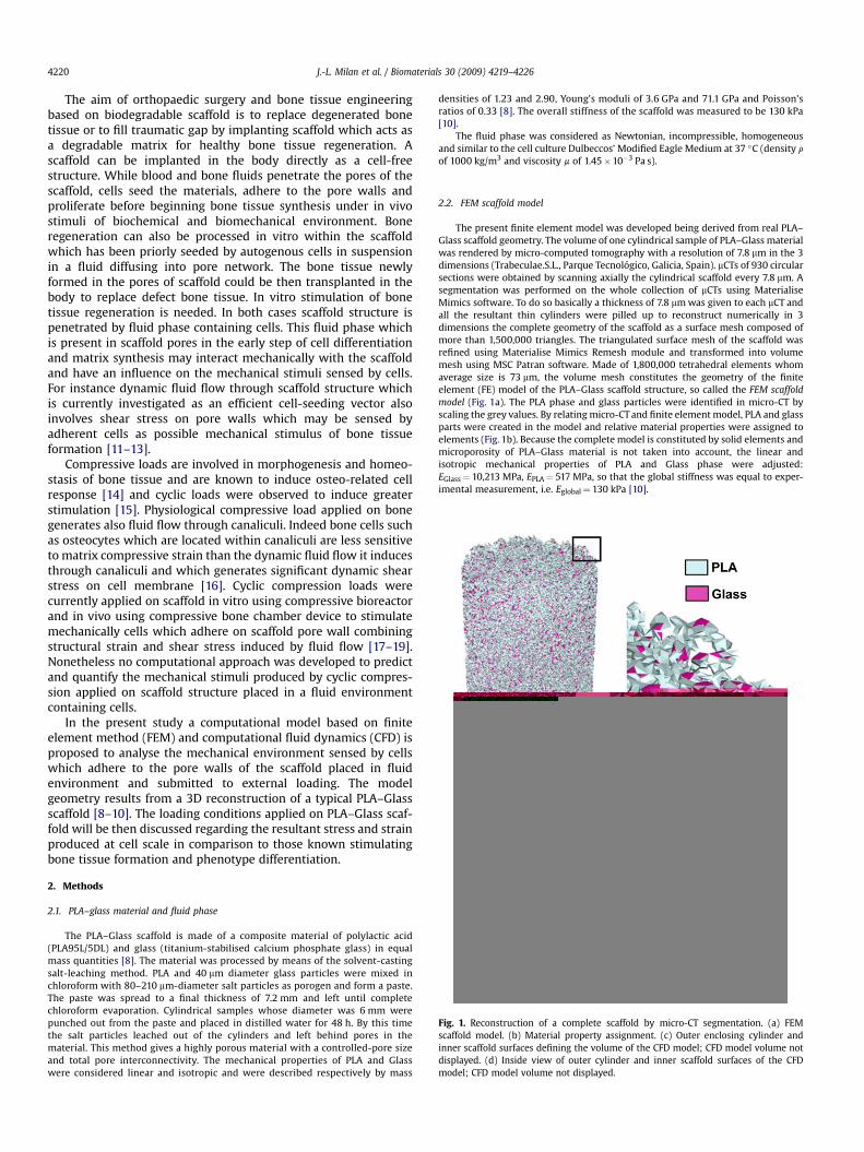
Fig. 1. Reconstruction of a complete scaffold by micro-CT segmentation. (a) FEMscaffold model. (b) Material property assignment. (c) Outer enclosing cylinder andinner scaffold surfaces defining the volume of the CFD model; CFD model volume notdisplayed. (d) Inside view of outer cylinder and inner scaffold surfaces of the CFDmodel; CFD model volume not displayed.
J.-L. Milan et al. / Biomaterials 30 (2009) 4219–42264220
The aim of orthopaedic surgery and bone tissue engineeringbased on biodegradable scaffold is to replace degenerated bonetissue or to fill traumatic gap by implanting scaffold which acts asa degradable matrix for healthy bone tissue regeneration. Ascaffold can be implanted in the body directly as a cell-freestructure. While blood and bone fluids penetrate the pores of thescaffold, cells seed the materials, adhere to the pore walls andproliferate before beginning bone tissue synthesis under in vivostimuli of biochemical and biomechanical environment. Boneregeneration can also be processed in vitro within the scaffoldwhich has been priorly seeded by autogenous cells in suspensionin a fluid diffusing into pore network. The bone tissue newlyformed in the pores of scaffold could be then transplanted in thebody to replace defect bone tissue. In vitro stimulation of bonetissue regeneration is needed. In both cases scaffold structure ispenetrated by fluid phase containing cells. This fluid phase whichis present in scaffold pores in the early step of cell differentiationand matrix synthesis may interact mechanically with the scaffoldand have an influence on the mechanical stimuli sensed by cells.For instance dynamic fluid flow through scaffold structure whichis currently investigated as an efficient cell-seeding vector alsoinvolves shear stress on pore walls which may be sensed byadherent cells as possible mechanical stimulus of bone tissueformation [11–13].
Compressive loads are involved in morphogenesis and homeo-stasis of bone tissue and are known to induce osteo-related cellresponse [14] and cyclic loads were observed to induce greaterstimulation [15]. Physiological compressive load applied on bonegenerates also fluid flow through canaliculi. Indeed bone cells suchas osteocytes which are located within canaliculi are less sensitiveto matrix compressive strain than the dynamic fluid flow it inducesthrough canaliculi and which generates significant dynamic shearstress on cell membrane [16]. Cyclic compression loads werecurrently applied on scaffold in vitro using compressive bioreactorand in vivo using compressive bone chamber device to stimulatemechanically cells which adhere on scaffold pore wall combiningstructural strain and shear stress induced by fluid flow [17–19].Nonetheless no computational approach was developed to predictand quantify the mechanical stimuli produced by cyclic compres-sion applied on scaffold structure placed in a fluid environmentcontaining cells.
In the present study a computational model based on finiteelement method (FEM) and computational fluid dynamics (CFD) isproposed to analyse the mechanical environment sensed by cellswhich adhere to the pore walls of the scaffold placed in fluidenvironment and submitted to external loading. The modelgeometry results from a 3D reconstruction of a typical PLA–Glassscaffold [8–10]. The loading conditions applied on PLA–Glass scaf-fold will be then discussed regarding the resultant stress and strainproduced at cell scale in comparison to those known stimulatingbone tissue formation and phenotype differentiation.
2. Methods
2.1. PLA–glass material and fluid phase
The PLA–Glass scaffold is made of a composite material of polylactic acid(PLA95L/5DL) and glass (titanium-stabilised calcium phosphate glass) in equalmass quantities [8]. The material was processed by means of the solvent-castingsalt-leaching method. PLA and 40 mm diameter glass particles were mixed inchloroform with 80–210 mm-diameter salt particles as porogen and form a paste.The paste was spread to a final thickness of 7.2 mm and left until completechloroform evaporation. Cylindrical samples whose diameter was 6 mm werepunched out from the paste and placed in distilled water for 48 h. By this timethe salt particles leached out of the cylinders and left behind pores in thematerial. This method gives a highly porous material with a controlled-pore sizeand total pore interconnectivity. The mechanical properties of PLA and Glasswere considered linear and isotropic and were described respectively by mass
densities of 1.23 and 2.90, Young’s moduli of 3.6 GPa and 71.1 GPa and Poisson’sratios of 0.33 [8]. The overall stiffness of the scaffold was measured to be 130 kPa[10].
The fluid phase was considered as Newtonian, incompressible, homogeneousand similar to the cell culture Dulbeccos’ Modified Eagle Medium at 37 �C (density r
of 1000 kg/m3 and viscosity m of 1.45�10�3 Pa s).
2.2. FEM scaffold model
The present finite element model was developed being derived from real PLA–Glass scaffold geometry. The volume of one cylindrical sample of PLA–Glass materialwas rendered by micro-computed tomography with a resolution of 7.8 mm in the 3dimensions (Trabeculae.S.L., Parque Tecnologico, Galicia, Spain). mCTs of 930 circularsections were obtained by scanning axially the cylindrical scaffold every 7.8 mm. Asegmentation was performed on the whole collection of mCTs using MaterialiseMimics software. To do so basically a thickness of 7.8 mm was given to each mCT andall the resultant thin cylinders were pilled up to reconstruct numerically in 3dimensions the complete geometry of the scaffold as a surface mesh composed ofmore than 1,500,000 triangles. The triangulated surface mesh of the scaffold wasrefined using Materialise Mimics Remesh module and transformed into volumemesh using MSC Patran software. Made of 1,800,000 tetrahedral elements whomaverage size is 73 mm, the volume mesh constitutes the geometry of the finiteelement (FE) model of the PLA–Glass scaffold structure, so called the FEM scaffoldmodel (Fig. 1a). The PLA phase and glass particles were identified in micro-CT byscaling the grey values. By relating micro-CT and finite element model, PLA and glassparts were created in the model and relative material properties were assigned toelements (Fig. 1b). Because the complete model is constituted by solid elements andmicroporosity of PLA–Glass material is not taken into account, the linear andisotropic mechanical properties of PLA and Glass phase were adjusted:EGlass¼ 10,213 MPa, EPLA¼ 517 MPa, so that the global stiffness was equal to exper-imental measurement, i.e. Eglobal¼ 130 kPa [10].

J.-L. Milan et al. / Biomaterials 30 (2009) 4219–4226 4221
2.3. Computational fluid dynamics (CFD) model
The fluid phase was represented to fill the scaffold pores and was delimited bythe walls of a virtual bioreactor which was assumed to be a cylinder of diameter andheight of 6.5 and 7.5 mm respectively (Fig. 1c and d). The gap which is considered inthe modelling between the scaffold and the bioreactor walls was assumed toreproduce experimental conditions allowing scaffold insertion and removal. Thefluid phase volume was meshed using MSC Patran Software and decomposed in6,180,000 tetrahedral elements constituting the geometry of the so-called CFDmodel.
2.4. Loading cases – perfusion test
Perfusion test of PLA–Glass scaffold placed in a cylindrical bioreactor wasreproduced in the CFD model (Fig. 2a). Steady fluid flow was applied throughscaffold pore network by imposing equal inlet and outlet velocities v of 100 mm/srespectively at the top and the bottom of the model. Scaffold deformation inducedby fluid flow was neglected and fluid was supposed to flow through fixed and non-deformable scaffold structure. The lateral cylindrical face and the scaffold–fluidinterface surface were considered as impermeable and rigid non-slip walls. The fluidwas considered as Newtonian, incompressible and homogeneous. The Reynoldsnumber Re was calculated preliminarily as
Re ¼ Drv=m (1)
with D, the maximal pore diameter (500 mm). Reynolds number being equal to0.035 and so far much lower than 2300, laminar flow was considered. The Navier–Stokes equation of steady flow of incompressible fluid
rðvVÞv ¼ �Vpþ mV2v (2)
was solved linearly with pressure–velocity simple coupling and a standard dis-cretization scheme for pressure.
The pressure-based solver was chosen to obtain fast-converging solutions andwas used with a node-based Green–Gauss gradient treatment which achieveshigher accuracy in unstructured triangular grids compared to the cell-basedgradient treatment. The fluid flow perfusion test was performed using FLUENT6.3.26. Fluid velocities and pressures were calculated as well as shear stressgenerated on pore walls by fluid flow.
2.5. Loading cases – dynamic compression
A dynamic compressions of overall level L of 5% at an overall strain rate Rof 1 s�1 were simulated on the system composed by the scaffold and the fluidphase placed in a virtual cylindrical bioreactor and were computed using FEMand CFD models in separated analyses (Fig. 2b). The influence of the overalldeformation level L was tested by performing static compression using scaf-fold FEM model alone and neglecting time effect and transient fluiddisplacement produced through scaffold structure by compression (Fig. 2b-i).The influence of overall deformation rate R was tested by using the CFD model
Fig. 2. (a) Perfusion test. Fluid flow velocities represented by white arrows were imposedExternal yellow surface as well as scaffold surface in gray were considered as non-slip wdisplacement represented by an arrow and applied to top nodes while bottom ones were firepresented by white arrow. The whole lateral surface in red was considered as a nullcompression. The null pressure gauge outlet was limited to the lower part of the lateral sur
alone and performing transient fluid flow which results from fluid displace-ment produced by compression while low scaffold deformation was neglected(Fig. 2b-ii and iii).
In the FE simulation of static compression, fixed boundary conditions wereimposed to the nodes of scaffold bottom while displacement of HL was applied onthe top nodes, H being the height of the scaffold. The structure was confined tolateral cylindrical face to simulate the bioreactor wall. Isotropic linear elastic lawswere used to define material properties. During compression simulation, FEM modelwas not mapped to possible CT scans of real scaffold placed under loading. Theproblem was computed on DS Simulia Abaqus using direct matrix solver. The overallmechanical response and the distribution of local strain and stress are expected asresults in terms of overall reaction force, principal stresses and strains, as well asoctahedral shear stress and strain.
In the CFD simulation scaffold deformation was neglected since compressionlevels were considered low and fluid was forced to flow through fixed scaffoldstructure. The bottom face of the CFD model and the scaffold–fluid interface surfaceare considered as fixed, impermeable and rigid non-slip walls. To reproduceunconfined fluid flow such as in a bioreactor wide opened, the whole lateralcylindrical face was considered as an opening and was modeled as a null gaugepressure-outlet (Fig. 2b-ii). A second case was considered in which fluid flow isconfined to the lateral cylindrical face except in the low part which remains opened(Fig. 2b-iii). This opening of a height of 1.75 mm from the bottom has the same areaas the inlet top side to avoid constriction of flow and was modeled as a null gaugepressure outlet.
Compressing the system to a level L at a rate R imposes to the top face andduring 1/R seconds a transient fluid flow velocity whose amplitude V¼ LHR.Pressure-based solver was used with node-based Green–Gauss gradient treatment.Second-order implicit unsteady formulation was used in the simulation withsupposed laminar conditions of flow. Second-order discretization scheme was usedfor pressure calculation and a second-order upwind scheme was used formomentum equations.
Pressure–velocity coupling was solved using SIMPLE scheme. One fixed timestep of 1/R second was used. A maximum of 100 iterations per time step wassufficient to reach a converged solution with residuals values lower than 0.001.
3. Results
3.1. Image rendering of PLA–glass scaffold
The scaffold FEM model which resulted from micro-computedtomography and image segmentation of PLA–Glass material(Fig. 1a) has a high porosity equal to 90% and a pore inter-connectivity equal to 100%. The cylindrical sample of PLA–Glassmaterial whose diameter and height are respectively 6 and 7.2 mmoccupies 25 mm3 of material and has a total wall pore surface of1790 mm2 which lead to ratio between surface and volume about73 mm2/mm3.
to the top and bottom faces (in blue) of the CFD model to reproduce perfusion test.alls. (b) Compression test. 1 – Static compression on FEM scaffold model by an axialxed. 2 – Transient fluid flow velocity through CFD model induced by compression andpressure gauge outlet. 3 – Transient fluid flow through the CFD model induced byface marked in red, the other part marked in yellow was considered as a non-slip wall.
J.-L. Milan et al. / Biomaterials 30 (2009) 4219–42264222
3.2. Perfusion through PLA–glass scaffold
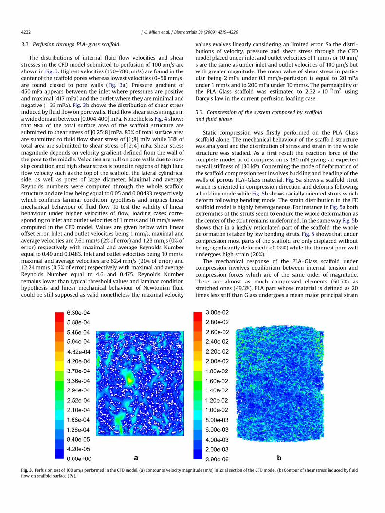
The distributions of internal fluid flow velocities and shearstresses in the CFD model submitted to perfusion of 100 mm/s areshown in Fig. 3. Highest velocities (150–780 mm/s) are found in thecenter of the scaffold pores whereas lowest velocities (0–50 mm/s)are found closed to pore walls (Fig. 3a). Pressure gradient of450 mPa appears between the inlet where pressures are positiveand maximal (417 mPa) and the outlet where they are minimal andnegative (�33 mPa). Fig. 3b shows the distribution of shear stressinduced by fluid flow on pore walls. Fluid flow shear stress ranges ina wide domain between [0.004;400] mPa. Nonetheless Fig. 4 showsthat 98% of the total surface area of the scaffold structure aresubmitted to shear stress of [0.25;8] mPa. 80% of total surface areaare submitted to fluid flow shear stress of [1;8] mPa while 33% oftotal area are submitted to shear stress of [2;4] mPa. Shear stressmagnitude depends on velocity gradient defined from the wall ofthe pore to the middle. Velocities are null on pore walls due to non-slip condition and high shear stress is found in regions of high fluidflow velocity such as the top of the scaffold, the lateral cylindricalside, as well as pores of large diameter. Maximal and averageReynolds numbers were computed through the whole scaffoldstructure and are low, being equal to 0.05 and 0.00483 respectively,which confirms laminar condition hypothesis and implies linearmechanical behaviour of fluid flow. To test the validity of linearbehaviour under higher velocities of flow, loading cases corre-sponding to inlet and outlet velocities of 1 mm/s and 10 mm/s werecomputed in the CFD model. Values are given below with linearoffset error. Inlet and outlet velocities being 1 mm/s, maximal andaverage velocities are 7.61 mm/s (2% of error) and 1.23 mm/s (0% oferror) respectively with maximal and average Reynolds Numberequal to 0.49 and 0.0483. Inlet and outlet velocities being 10 mm/s,maximal and average velocities are 62.4 mm/s (20% of error) and12.24 mm/s (0.5% of error) respectively with maximal and averageReynolds Number equal to 4.6 and 0.475. Reynolds Numberremains lower than typical threshold values and laminar conditionhypothesis and linear mechanical behaviour of Newtonian fluidcould be still supposed as valid nonetheless the maximal velocity
Fig. 3. Perfusion test of 100 mm/s performed in the CFD model. (a) Contour of velocity magniflow on scaffold surface (Pa).
values evolves linearly considering an limited error. So the distri-butions of velocity, pressure and shear stress through the CFDmodel placed under inlet and outlet velocities of 1 mm/s or 10 mm/s are the same as under inlet and outlet velocities of 100 mm/s butwith greater magnitude. The mean value of shear stress in partic-ular being 2 mPa under 0.1 mm/s-perfusion is equal to 20 mPaunder 1 mm/s and to 200 mPa under 10 mm/s. The permeability ofthe PLA–Glass scaffold was estimated to 2.32�10�9 m2 usingDarcy’s law in the current perfusion loading case.
3.3. Compression of the system composed by scaffoldand fluid phase
Static compression was firstly performed on the PLA–Glassscaffold alone. The mechanical behaviour of the scaffold structurewas analyzed and the distribution of stress and strain in the wholestructure was studied. As a first result the reaction force of thecomplete model at of compression is 180 mN giving an expectedoverall stiffness of 130 kPa. Concerning the mode of deformation ofthe scaffold compression test involves buckling and bending of thewalls of porous PLA–Glass material. Fig. 5a shows a scaffold strutwhich is oriented in compression direction and deforms followinga buckling mode while Fig. 5b shows radially oriented struts whichdeform following bending mode. The strain distribution in the FEscaffold model is highly heterogeneous. For instance in Fig. 5a bothextremities of the struts seem to endure the whole deformation asthe center of the strut remains undeformed. In the same way Fig. 5bshows that in a highly reticulated part of the scaffold, the wholedeformation is taken by few bending struts. Fig. 5 shows that undercompression most parts of the scaffold are only displaced withoutbeing significantly deformed (<0.02%) while the thinnest pore wallundergoes high strain (20%).
The mechanical response of the PLA–Glass scaffold undercompression involves equilibrium between internal tension andcompression forces which are of the same order of magnitude.There are almost as much compressed elements (50.7%) asstretched ones (49.3%). PLA part whose material is defined as 20times less stiff than Glass undergoes a mean major principal strain
tude (m/s) in axial section of the CFD model. (b) Contour of shear stress induced by fluid
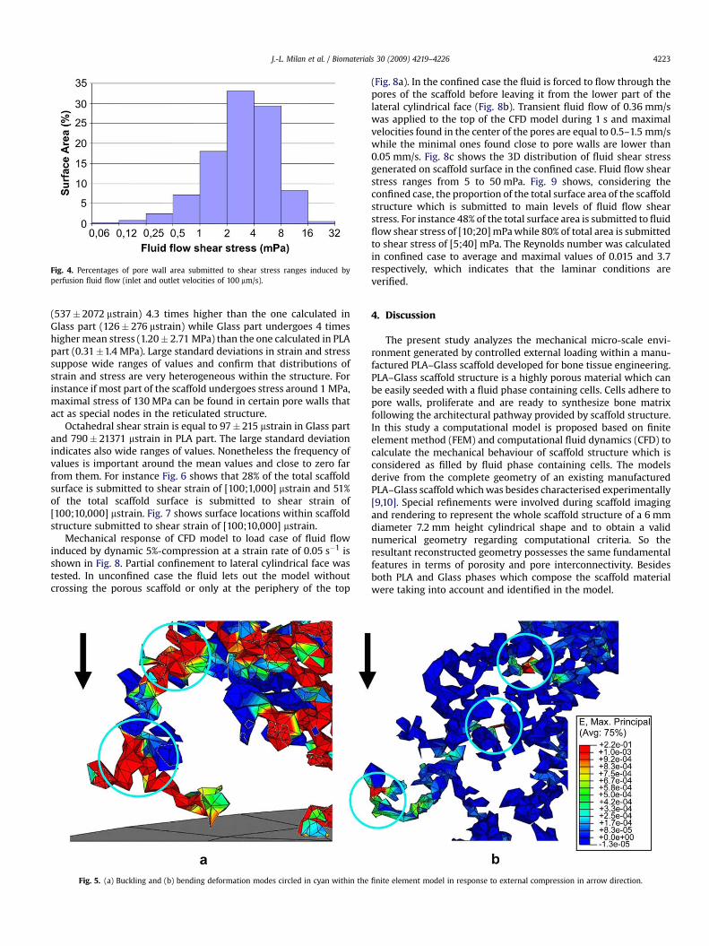
Fig. 4. Percentages of pore wall area submitted to shear stress ranges induced byperfusion fluid flow (inlet and outlet velocities of 100 mm/s).
J.-L. Milan et al. / Biomaterials 30 (2009) 4219–4226 4223
(537�2072 mstrain) 4.3 times higher than the one calculated inGlass part (126� 276 mstrain) while Glass part undergoes 4 timeshigher mean stress (1.20� 2.71 MPa) than the one calculated in PLApart (0.31�1.4 MPa). Large standard deviations in strain and stresssuppose wide ranges of values and confirm that distributions ofstrain and stress are very heterogeneous within the structure. Forinstance if most part of the scaffold undergoes stress around 1 MPa,maximal stress of 130 MPa can be found in certain pore walls thatact as special nodes in the reticulated structure.
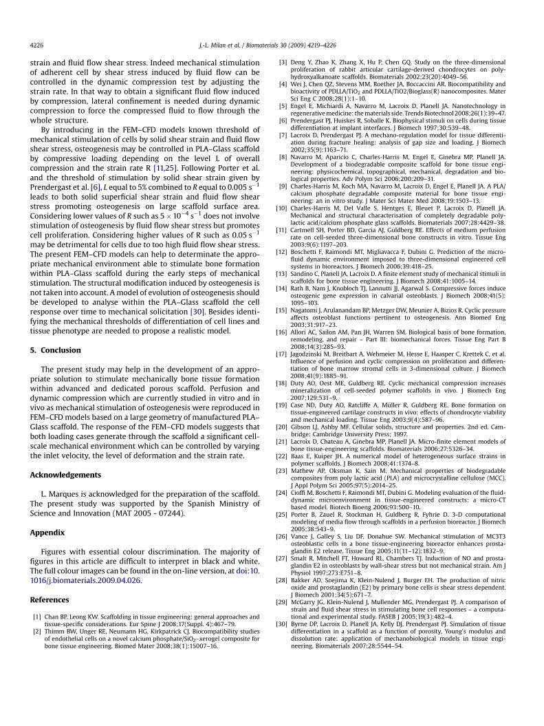
Octahedral shear strain is equal to 97� 215 mstrain in Glass partand 790� 21371 mstrain in PLA part. The large standard deviationindicates also wide ranges of values. Nonetheless the frequency ofvalues is important around the mean values and close to zero farfrom them. For instance Fig. 6 shows that 28% of the total scaffoldsurface is submitted to shear strain of [100;1,000] mstrain and 51%of the total scaffold surface is submitted to shear strain of[100;10,000] mstrain. Fig. 7 shows surface locations within scaffoldstructure submitted to shear strain of [100;10,000] mstrain.
Mechanical response of CFD model to load case of fluid flowinduced by dynamic 5%-compression at a strain rate of 0.05 s�1 isshown in Fig. 8. Partial confinement to lateral cylindrical face wastested. In unconfined case the fluid lets out the model withoutcrossing the porous scaffold or only at the periphery of the top
Fig. 5. (a) Buckling and (b) bending deformation modes circled in cyan within the
(Fig. 8a). In the confined case the fluid is forced to flow through thepores of the scaffold before leaving it from the lower part of thelateral cylindrical face (Fig. 8b). Transient fluid flow of 0.36 mm/swas applied to the top of the CFD model during 1 s and maximalvelocities found in the center of the pores are equal to 0.5–1.5 mm/swhile the minimal ones found close to pore walls are lower than0.05 mm/s. Fig. 8c shows the 3D distribution of fluid shear stressgenerated on scaffold surface in the confined case. Fluid flow shearstress ranges from 5 to 50 mPa. Fig. 9 shows, considering theconfined case, the proportion of the total surface area of the scaffoldstructure which is submitted to main levels of fluid flow shearstress. For instance 48% of the total surface area is submitted to fluidflow shear stress of [10;20] mPa while 80% of total area is submittedto shear stress of [5;40] mPa. The Reynolds number was calculatedin confined case to average and maximal values of 0.015 and 3.7respectively, which indicates that the laminar conditions areverified.
4. Discussion
The present study analyzes the mechanical micro-scale envi-ronment generated by controlled external loading within a manu-factured PLA–Glass scaffold developed for bone tissue engineering.PLA–Glass scaffold structure is a highly porous material which canbe easily seeded with a fluid phase containing cells. Cells adhere topore walls, proliferate and are ready to synthesize bone matrixfollowing the architectural pathway provided by scaffold structure.In this study a computational model is proposed based on finiteelement method (FEM) and computational fluid dynamics (CFD) tocalculate the mechanical behaviour of scaffold structure which isconsidered as filled by fluid phase containing cells. The modelsderive from the complete geometry of an existing manufacturedPLA–Glass scaffold which was besides characterised experimentally[9,10]. Special refinements were involved during scaffold imagingand rendering to represent the whole scaffold structure of a 6 mmdiameter 7.2 mm height cylindrical shape and to obtain a validnumerical geometry regarding computational criteria. So theresultant reconstructed geometry possesses the same fundamentalfeatures in terms of porosity and pore interconnectivity. Besidesboth PLA and Glass phases which compose the scaffold materialwere taking into account and identified in the model.
finite element model in response to external compression in arrow direction.

Fig. 6. Percentages of scaffold surface area submitted to ranges of superficial solidshear strain generated by 5%-compression.
J.-L. Milan et al. / Biomaterials 30 (2009) 4219–42264224
The mechanical behaviour of the PLA–Glass scaffold structurealone was studied in simulating in the FEM model 5% staticcompression. Under compressive loading, PLA–Glass materialdeformation involves a spatial reorganization by displacement ofthe internal structure which tends to relax strain energy. Most ofthe internal parts are mainly displaced being low stressed orstrained while the stress and strain concentrate on thinnest porewalls or walls acting as nodes of the reticulated structure. Thepresent study corroborates previous study led by Charles-Harriset al. in indicating that the PLA–Glass material deforms by bucklingand bending in some parts of the structure which is typical fromthin-walled porous materials [10,20]. Besides at 5%-compressedstate PLA–Glass scaffold involves an internal equilibrium betweenlocal tension and compression forces and heterogeneous distribu-tion of local strain and stress. The same mechanical behaviourunder compression loading was calculated in FE models of similarporous material made of CaP bone cement, CaP-based porous glassor pure PLLA [21,22]. Nonetheless even if the resultant local stressesand strains are quite low (1 MPa and 500 mstrain respectively) inreponse to overall compression some extreme values of stress andstrain (130 MPa and 200,000 mstrain respectively) were calculated
Fig. 7. Positions on scaffold surface submitted to shear strain of [
and may induce material damages. Unless the PLA part in thestudied PLA–Glass material has different mechanical propertiesthan those of pure PLA material (tensile and compressive strengthof 50 MPa, ultimate elongation from 2.4 to 10% [23]), this maximalstress and strain values would lead to material breakage in the fewconcerned points of the structure. Mesh refinement and introduc-tion of more realistic plastic laws in PLA material properties couldhelp in managing damage processes possibly occurring at rarelocations. Charles-Harris et al. in an experimental study of PLA–Glass scaffold mechanical characterisation reported wall breakageover 20% of overall compression [10].
From a biomechanical point of view, solid shear strain in therange of [100;10,000] mstrain is known to provide mechanicalstimuli of cellular osteogenesis [6]. Above 100,000 mstrain fibroustissue is formed while above 500,000 mstrain cells die. The presentresults show that applying 5%-compression loading on PLA–Glassscaffold generates on 51% of the surface a shear strain stimulatingosteogenesis.
Concerning the fluid flow perfusion analysis, results show thatinlet flow velocity of 0.1 mm/s induces on pore wall mean shearstress of 4 mPa. As the CFD analysis is linear, inlet flow velocities of0.001, 0.01 and 1 mm/s for instance will produce on pore wall,mean shear stress of 0.04 mPa, 0.4 mPa and 40 mPa respectively.The shear stress distribution calculated in the CFD model submittedto perfusion is consistent with results from previous numericalstudies. For instance, using CFD models based porous scaffoldimaged by micro-CT, Cioffi et al. calculated an average shear stresson pore walls of 3.48 mPa for an inlet velocity of 53 mm/s [24] whileSandino et al. calculated an average shear stress lower than 1 mPafor an inlet velocity of 10 mm/s [13]. Experimental studies ofperfusion were made on similar scaffold structures [11,25,26]. Forinstance, Cartmell et al. made experimental perfusion throughscaffold structure and studied the influence of fluid flow velocity onthe viability and differentiation of cells [11]. The scaffold wasa cylinder of 6.25 mm of diameter and height made of freeze-driedsterilized human trabecular bone whose porosity was measured tobe 82% and average pore size to be 645 mm. Porter et al. proposeda computational fluid dynamic model based on the structure usedby Cartmell et al. so as to calculate the resultant shear stressdistribution related to the inlet velocity and to discuss cell viabilityand differentiation using fluid flow-induced shear stress criteria[25,11]. They showed that the highest cell viability and proliferationwere obtained with fluid flow velocity of 0.005 mm/s generating on
100;10,000] mstrain generated by overall compression of 5%.
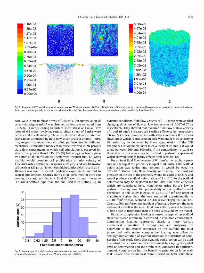
Fig. 8. Response of CFD model to dynamic compression of 5% at a strain rate of 0.05 s�1. Distribution of internal velocity represented by contours and vectors (a) in unconfined case,(b) in case confined partially to the lateral cylindrical face. (c) Distribution of shear stress generated on scaffold surface by fluid flow (Pa).
J.-L. Milan et al. / Biomaterials 30 (2009) 4219–4226 4225
pore walls a mean shear stress of 0.05 mPa. An upregulation ofosteo-related gene mRNA was observed as flow rate increased from0.005 to 0.1 mm/s leading to surface shear stress of 1 mPa. Flowrates of 0.5 mm/s involving surface shear stress of 5 mPa weredetrimental to cell viability. These results which demonstrate thatcells can be stimulated by fluid flow shear stress of around 1 mPa,may suggest that experimental scaffold perfusion implies differentmechanical stimulation modes than those involved in 2D parallelplate flow experiments in which cell stimulation is observed forshear stress greater than 0.5 Pa [27–29]. Following conclusion givenby Porter et al., perfusion test performed through the PLA–Glassscaffold would promote cell proliferation at inlet velocity of1.25 mm/s, osteo-related cell response at 25 mm/s and would involvecell death at 125 mm/s. Nonetheless highest inlet velocity such as 1–10 mm/s was used in scaffold perfusion experiments and led tocellular proliferation. Charles-Harris et al. performed in vitro cellseeding by static and dynamic fluid diffusion through the samePLA–Glass scaffold type than the one used is this study [9]. In
Fig. 9. Percentages of scaffold surface area submitted to ranges of fluid shear stressgenerated by dynamic compression of 5% at a strain rate of 0.05 s�1.
dynamic conditions, fluid flow velocity of 1–10 mm/s were appliedchanging direction of flow at low frequencies of 0.007–0.07 Hzrespectively. They showed that dynamic fluid flow at flow velocityof 1 and 10 mm/s increases cell seeding efficiency by respectively3.6 and 5.5 times in comparison with static conditions. If the meanshear stress which is produced on pore wall under inlet velocity of10 mm/s may be deducted by linear extrapolation of the CFDanalysis results obtained under inlet velocity of 0.1 mm/s, it wouldrange between 200 and 800 mPa. If the extrapolation is valid sothese shear stress values may be involved in perfusion experimentwhich showed besides highly efficient cell seeding [10].
For an inlet fluid flow velocity of 0.1 mm/s, the resultant pres-sure on the top of the geometry is equal to 417 mPa. If the scaffolddeformation was taking into account it would be equal to3.2�10�6. Under fluid flow velocity of 10 mm/s, the resultantpressure on the top of the geometry would be equal to 64.5 Pa andwould produce a scaffold deformation of 5�10�4. So the scaffolddeformation may be neglected for the inlet fluid flow velocitieswhich are considered here. Nonetheless using Darcy’s law inperfusion loading case the permeability of the scaffold modeldeveloped in this study is equal to 2.32�10�9 m2 one order ofmagnitude higher than the one measured experimentally to2�10�10 m2 on manufactured PLA–Glass scaffold [9]. Thus in PLA–Glass scaffold perfusion the gradient of pressure between the inletand outlet as well as the mean fluid flow velocity would be greaterof one order of magnitude than the ones calculated by the model.
Dynamic compression loading is currently applied on scaffoldstructure placed within an in vitro and in vivo fluid environment.Compression loading represents clearly a more realisticmechanical stimulation of osteogenesis, and analyzing thebehaviour of the system composed by the scaffold, the fluidphase and cells under compressive loading may allow toenvisage implantation of scaffold structure as substitute of bone.Results of this study show that dynamic compression can be usedto control the cell mechanical environment by varying the globallevel of deformation and the strain rate. Compared to perfusion,dynamic compression has the benefit to generate on large scaf-fold surface area mechanical stimuli based on both solid shear
J.-L. Milan et al. / Biomaterials 30 (2009) 4219–42264226
strain and fluid flow shear stress. Indeed mechanical stimulationof adherent cell by shear stress induced by fluid flow can becontrolled in the dynamic compression test by adjusting thestrain rate. In that way to obtain a significant fluid flow inducedby compression, lateral confinement is needed during dynamiccompression to force the compressed fluid to flow through thewhole structure.
By introducing in the FEM–CFD models known threshold ofmechanical stimulation of cells by solid shear strain and fluid flowshear stress, osteogenesis may be controlled in PLA–Glass scaffoldby compressive loading depending on the level L of overallcompression and the strain rate R [11,25]. Following Porter et al.and the threshold of stimulation by solid shear strain given byPrendergast et al. [6], L equal to 5% combined to R equal to 0.005 s�1
leads to both solid superficial shear strain and fluid flow shearstress promoting osteogenesis on large scaffold surface area.Considering lower values of R such as 5�10�4 s�1 does not involvestimulation of osteogenesis by fluid flow shear stress but promotescell proliferation. Considering higher values of R such as 0.05 s�1
may be detrimental for cells due to too high fluid flow shear stress.The present FEM–CFD models can help to determinate the appro-priate mechanical environment able to stimulate bone formationwithin PLA–Glass scaffold during the early steps of mechanicalstimulation. The structural modification induced by osteogenesis isnot taken into account. A model of evolution of osteogenesis shouldbe developed to analyse within the PLA–Glass scaffold the cellresponse over time to mechanical solicitation [30]. Besides identi-fying the mechanical thresholds of differentiation of cell lines andtissue phenotype are needed to propose a realistic model.
5. Conclusion
The present study may help in the development of an appro-priate solution to stimulate mechanically bone tissue formationwithin advanced and dedicated porous scaffold. Perfusion anddynamic compression which are currently studied in vitro and invivo as mechanical stimulation of osteogenesis were reproduced inFEM–CFD models based on a large geometry of manufactured PLA–Glass scaffold. The response of the FEM–CFD models suggests thatboth loading cases generate through the scaffold a significant cell-scale mechanical environment which can be controlled by varyingthe inlet velocity, the level of deformation and the strain rate.
Acknowledgements
L. Marques is acknowledged for the preparation of the scaffold.The present study was supported by the Spanish Ministry ofScience and Innovation (MAT 2005 - 07244).
Appendix
Figures with essential colour discrimination. The majority offigures in this article are difficult to interpret in black and white.The full colour images can be found in the on-line version, at doi:10.1016/j.biomaterials.2009.04.026.
References
[1] Chan BP, Leong KW. Scaffolding in tissue engineering: general approaches andtissue-specific considerations. Eur Spine J 2008;17(Suppl. 4):467–79.
[2] Thimm BW, Unger RE, Neumann HG, Kirkpatrick CJ. Biocompatibility studiesof endothelial cells on a novel calcium phosphate/SiO2–xerogel composite forbone tissue engineering. Biomed Mater 2008;38(1):15007–16.
[3] Deng Y, Zhao K, Zhang X, Hu P, Chen GQ. Study on the three-dimensionalproliferation of rabbit articular cartilage-derived chondrocytes on poly-hydroxyalkanoate scaffolds. Biomaterials 2002;23(20):4049–56.
[4] Wei J, Chen QZ, Stevens MM, Roether JA, Boccaccini AR. Biocompatibility andbioactivity of PDLLA/TiO2 and PDLLA/TiO2/Bioglass(R) nanocomposites. MaterSci Eng C 2008;28(1):1–10.
[5] Engel E, Michiardi A, Navarro M, Lacroix D, Planell JA. Nanotechnology inregenerative medicine: the materials side. Trends Biotechnol 2008;26(1):39–47.
[6] Prendergast PJ, Huiskes R, Soballe K. Biophysical stimuli on cells during tissuedifferentiation at implant interfaces. J Biomech 1997;30:539–48.
[7] Lacroix D, Prendergast PJ. A mechano-regulation model for tissue differenti-ation during fracture healing: analysis of gap size and loading. J Biomech2002;35(9):1163–71.
[8] Navarro M, Aparicio C, Charles-Harris M, Engel E, Ginebra MP, Planell JA.Development of a biodegradable composite scaffold for bone tissue engi-neering: physicochemical, topographical, mechanical, degradation and bio-logical properties. Adv Polym Sci 2006;200:209–31.
[9] Charles-Harris M, Koch MA, Navarro M, Lacroix D, Engel E, Planell JA. A PLA/calcium phosphate degradable composite material for bone tissue engi-neering: an in vitro study. J Mater Sci Mater Med 2008;19:1503–13.
[10] Charles-Harris M, Del Valle S, Hentges E, Bleuet P, Lacroix D, Planell JA.Mechanical and structural characterisation of completely degradable poly-lactic acid/calcium phosphate glass scaffolds. Biomaterials 2007;28:4429–38.
[11] Cartmell SH, Porter BD, Garcia AJ, Guldberg RE. Effects of medium perfusionrate on cell-seeded three-dimensional bone constructs in vitro. Tissue Eng2003;9(6):1197–203.
[12] Boschetti F, Raimondi MT, Migliavacca F, Dubini G. Prediction of the micro-fluid dynamic environment imposed to three-dimensional engineered cellsystems in bioreactors. J Biomech 2006;39:418–25.
[13] Sandino C, Planell JA, Lacroix D. A finite element study of mechanical stimuli inscaffolds for bone tissue engineering. J Biomech 2008;41:1005–14.
[14] Rath B, Nam J, Knobloch TJ, Lannutti JJ, Agarwal S. Compressive forces induceosteogenic gene expression in calvarial osteoblasts. J Biomech 2008;41(5):1095–103.
[15] Nagatomi J, Arulanandam BP, Metzger DW, Meunier A, Bizios R. Cyclic pressureaffects osteoblast functions pertinent to osteogenesis. Ann Biomed Eng2003;31:917–23.
[16] Allori AC, Sailon AM, Pan JH, Warren SM. Biological basis of bone formation,remodeling, and repair – Part III: biomechanical forces. Tissue Eng Part B2008;14(3):285–93.
[17] Jagodzinski M, Breitbart A, Wehmeier M, Hesse E, Haasper C, Krettek C, et al.Influence of perfusion and cyclic compression on proliferation and differen-tiation of bone marrow stromal cells in 3-dimensional culture. J Biomech2008;41(9):1885–91.
[18] Duty AO, Oest ME, Guldberg RE. Cyclic mechanical compression increasesmineralization of cell-seeded polymer scaffolds in vivo. J Biomech Eng2007;129:531–9.
[19] Case ND, Duty AO, Ratcliffe A, Muller R, Guldberg RE. Bone formation ontissue-engineered cartilage constructs in vivo: effects of chondrocyte viabilityand mechanical loading. Tissue Eng 2003;9(4):587–96.
[20] Gibson LJ, Ashby MF. Cellular solids, structure and properties. 2nd ed. Cam-bridge: Cambridge University Press; 1997.
[21] Lacroix D, Chateau A, Ginebra MP, Planell JA. Micro-finite element models ofbone tissue-engineering scaffolds. Biomaterials 2006;27:5326–34.
[22] Baas E, Kuiper JH. A numerical model of heterogeneous surface strains inpolymer scaffolds. J Biomech 2008;41:1374–8.
[23] Mathew AP, Oksman K, Sain M. Mechanical properties of biodegradablecomposites from poly lactic acid (PLA) and microcrystalline cellulose (MCC).J Appl Polym Sci 2005;97(5):2014–25.
[24] Cioffi M, Boschetti F, Raimondi MT, Dubini G. Modeling evaluation of the fluid-dynamic microenvironment in tissue-engineered constructs: a micro-CTbased model. Biotech Bioeng 2006;93:500–10.
[25] Porter B, Zauel R, Stockman H, Guldberg R, Fyhrie D. 3-D computationalmodeling of media flow through scaffolds in a perfusion bioreactor. J Biomech2005;38:543–9.
[26] Vance J, Galley S, Liu DF, Donahue SW. Mechanical stimulation of MC3T3osteoblastic cells in a bone tissue-engineering bioreactor enhances prosta-glandin E2 release. Tissue Eng 2005;11(11–12):1832–9.
[27] Smalt R, Mitchell FT, Howard RL, Chambers TJ. Induction of NO and prosta-glandin E2 in osteoblasts by wall-shear stress but not mechanical strain. Am JPhysiol 1997;273:E751–8.
[28] Bakker AD, Soejima K, Klein-Nulend J, Burger EH. The production of nitricoxide and prostaglandin (E2) by primary bone cells is shear stress dependent.J Biomech 2001;34(5):671–7.
[29] McGarry JG, Klein-Nulend J, Mullender MG, Prendergast PJ. A comparison ofstrain and fluid shear stress in stimulating bone cell responses – a computa-tional and experimental study. FASEB J 2005;19(3):482–4.
[30] Byrne DP, Lacroix D, Planell JA, Kelly DJ, Prendergast PJ. Simulation of tissuedifferentiation in a scaffold as a function of porosity, Young’s modulus anddissolution rate: application of mechanobiological models in tissue engi-neering. Biomaterials 2007;28:5544–54.