Embed Size (px)
Citation preview

Journal of Emerging Trends in Engineering and Applied Sciences (JETEAS) 2 (5): 821-825 (ISSN: 2141-7016)
821
Computer Aided Design of Dashpot for 0.040-2ton
Vibrating Machines
1Adeyeri M. K., 1Ayodeji S. P, 1Emovon I., 2Adesina F., 2Oguntuyi V. F.
1Engineering and Engineering Technology/Department of Mechanical Engineering The Federal University of Technology Akure, Akure Ondo State, Nigeria
2Engineering and Engineering Technology/Department of Mechanical Engineering Rufus Giwa Polytechnic, Owo Ondo State, Owo, Ondo State, Nigeria
Corresponding Author: Adeyeri M. K ___________________________________________________________________________ Abstract Building cracks and failures are proned to areas where machinery are being used, especially in locations where domesticated activities like grinding, milling turning operations and just to mention afew are means of livelihood. As these activities are being carried out daily, there is possibilty of setting the neighbouring and adjacent buildings into vibration. In order to avert the inherent danger of building collapse, this research work, Computer aided design of dashpot for machinery with masses between 40Kg and 2000Kg is necessitated for. The dashpot is designed after the similitude of an automobile shock absorber. It comprises cylinder (piston housing), piston, connecting rod (shaft), spring, rubber pad or silencer rubber, plate (load carrier), fluid and rubber seal. The work done was designed using virtual engineering through Computer aided design and simulation of the dashpot in AUTOCAD together with 3D studio max. Adobe premiere and Visual Basic 6.0 is used to design parts of the interfaces for simulation to see the effect of this when being loaded with machinery of various tonnages. The still images are edited with adobe Photoshop and fireworks, and the text animation was done with Adobe premiere. The result of the research work is moderately perfected and the knowledge has therein could be used in designing for other machinery as the need arises __________________________________________________________________________________________ Keywords: computer aided design, dash pot, vibration, vibrating machines, Visual Basic 6.0 __________________________________________________________________________________________ INTRODUCTION It is obvious that machinery such as forging hammer, grinding machine, lathe machine, drilling machine mounted on production shops do disturb the environment when in use. They respond to frequency variation as they start running and become manifest in the form of mechanical vibration. As they approach the resonating frequency, the foundation or floor on which they are mounted is momentarily excited into a state of vibration, thus, the flooring will begin to show sign of cracking/fracture until the machine starts to sink. Thus to disallow this devastating effect, this research work therefore centers on how to isolate vibration caused by household machinery of 40kg-2000Kg by the use of dash pot(s). Civil engineers designed machinery foundation to spread the load of installed machinery into the ground so that excessive settlement or tilting of the foundation block relative to the floor or other fixed installations will not occur under stresses set up by heavy concentrated loads or by unbalanced rotating or reciprocating machinery (Tomlinson, 1986). Many researchers have studied the influence of various parameters of the isolator mounting system on the impact force transmitted to soil, and
introduced a number of dynamic models for one-mass and two-mass foundations with springs and dampers. Guoqiang and Zuomin (2005) formulated optimization model to minimize the maximum impact force transmissibility under design constraints, using stiffness and damping coefficients of the isolator, mass of the foundation block and support area of soil as design variables. Nevertheless, with the design by these professionals, problems are still arising on the foundation designed for machinery having unbalanced moving parts such as large flywheels, crankshaft or the piston of reciprocating engine. They set up vibration in the foundation blocks which if not absorbed by anti vibration mountings are transmitted to the ground, strong ground vibration may cause loss of bearing capacity and settlement of soil beneath the foundation; they may also cause damage to the adjacent buildings or machines.(Robert, 1992; Robert, 1972). Therefore, in order to keep down the transmitted vibration to minimal, a vibration isolation system (e.g Dash pot/damper) has to be introduced (Adeyeri, 2001).
Journal of Emerging Trends in Engineering and Applied Sciences (JETEAS) 2 (5): 821-825 © Scholarlink Research Institute Journals, 2011 (ISSN: 2141-7016) jeteas.scholarlinkresearch.org
Journal of Emerging Trends in Engineering and Applied Sciences (JETEAS) 2 (5): 821-825 (ISSN: 2141-7016)
822
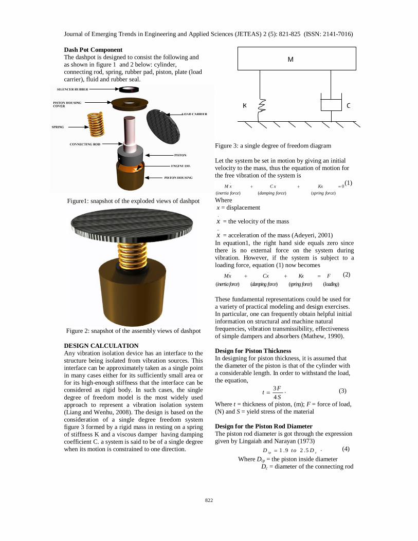
Dash Pot Component The dashpot is designed to consist the following and as shown in figure 1 and 2 below: cylinder, connecting rod, spring, rubber pad, piston, plate (load carrier), fluid and rubber seal.
Figure1: snapshot of the exploded views of dashpot
Figure 2: snapshot of the assembly views of dashpot
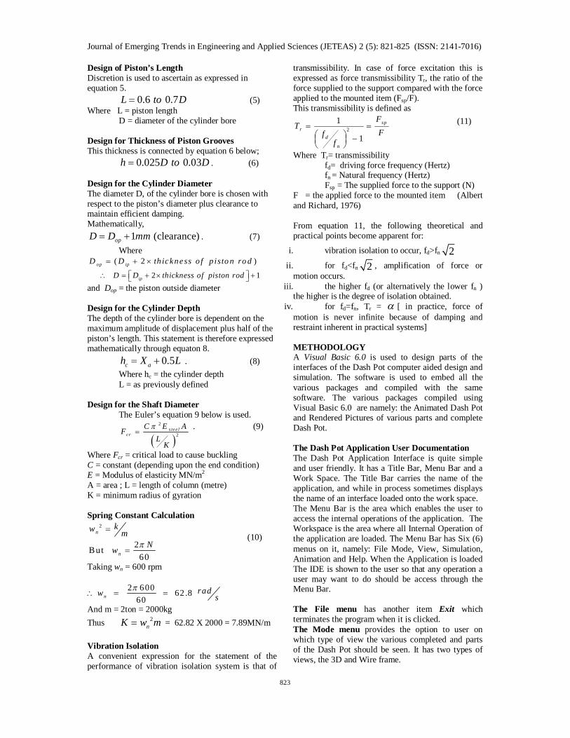
DESIGN CALCULATION Any vibration isolation device has an interface to the structure being isolated from vibration sources. This interface can be approximately taken as a single point in many cases either for its sufficiently small area or for its high-enough stiffness that the interface can be considered as rigid body. In such cases, the single degree of freedom model is the most widely used approach to represent a vibration isolation system (Liang and Wenhu, 2008). The design is based on the consideration of a single degree freedom system figure 3 formed by a rigid mass in resting on a spring of stiffness K and a viscous damper having damping coefficient C. a system is said to be of a single degree when its motion is constrained to one direction.
Figure 3: a single degree of freedom diagram Let the system be set in motion by giving an initial velocity to the mass, thus the equation of motion for the free vibration of the system is
.. . 0( ) ( ) ( )
M x C x Kxinertia force damping force spring force
(1)
Where x = displacement
.x = the velocity of the mass ..x = acceleration of the mass (Adeyeri, 2001)
In equation1, the right hand side equals zero since there is no external force on the system during vibration. However, if the system is subject to a loading force, equation (1) now becomes
.. . ( ) ( ) ( ) ( )
Mx Cx Kx Finertiaforce damping force spring force loading
(2)
These fundamental representations could be used for a variety of practical modeling and design exercises. In particular, one can frequently obtain helpful initial information on structural and machine natural frequencies, vibration transmissibility, effectiveness of simple dampers and absorbers (Mathew, 1990). Design for Piston Thickness In designing for piston thickness, it is assumed that the diameter of the piston is that of the cylinder with a considerable length. In order to withstand the load, the equation, 3
4FtS
. (3)
Where t = thickness of piston, (m); F = force of load, (N) and S = yield stress of the material Design for the Piston Rod Diameter The piston rod diameter is got through the expression given by Lingaiah and Narayan (1973) 1 .9 2 .5i p cD to D . (4) Where Dip = the piston inside diameter Dc = diameter of the connecting rod
C K
M
Journal of Emerging Trends in Engineering and Applied Sciences (JETEAS) 2 (5): 821-825 (ISSN: 2141-7016)
823
Design of Piston’s Length Discretion is used to ascertain as expressed in equation 5. 0.6 0.7L to D (5) Where L = piston length D = diameter of the cylinder bore Design for Thickness of Piston Grooves This thickness is connected by equation 6 below; 0.025 0.03h D to D . (6) Design for the Cylinder Diameter The diameter D, of the cylinder bore is chosen with respect to the piston’s diameter plus clearance to maintain efficient damping. Mathematically,
1 (clearance)opD D mm . (7) Where
( 2 )op ipD D th ickness o f p isto n ro d 2 1ipD D thickness of piston rod
and Dop = the piston outside diameter Design for the Cylinder Depth The depth of the cylinder bore is dependent on the maximum amplitude of displacement plus half of the piston’s length. This statement is therefore expressed mathematically through equaton 8. 0.5c ah X L . (8) Where hc = the cylinder depth L = as previously defined Design for the Shaft Diameter The Euler’s equation 9 below is used.
2
2s te e l
c rC E AF
LK
. (9)
Where Fcr = critical load to cause buckling C = constant (depending upon the end condition) E = Modulus of elasticity MN/m2 A = area ; L = length of column (metre) K = minimum radius of gyration Spring Constant Calculation
2
2But 60
n
n
kw mNw
(10)
Taking wn = 600 rpm
2 600 62 .8 60n
radw s
And m = 2ton = 2000kg Thus 2
nK w m = 62.82 X 2000 = 7.89MN/m Vibration Isolation A convenient expression for the statement of the performance of vibration isolation system is that of
transmissibility. In case of force excitation this is expressed as force transmissibility Tr, the ratio of the force supplied to the support compared with the force applied to the mounted item (Fsp/F). This transmissibility is defined as
21
1
spr
d
n
FT
Fff
(11)
Where Tr= transmissibility fd= driving force frequency (Hertz)
fn = Natural frequency (Hertz) Fsp = The supplied force to the support (N) F = the applied force to the mounted item (Albert and Richard, 1976) From equation 11, the following theoretical and practical points become apparent for:
i. vibration isolation to occur, fd>fn 2
ii. for fd<fn 2 , amplification of force or motion occurs.
iii. the higher fd (or alternatively the lower fn ) the higher is the degree of isolation obtained.
iv. for fd=fn, Tr = [ in practice, force of motion is never infinite because of damping and restraint inherent in practical systems] METHODOLOGY A Visual Basic 6.0 is used to design parts of the interfaces of the Dash Pot computer aided design and simulation. The software is used to embed all the various packages and compiled with the same software. The various packages compiled using Visual Basic 6.0 are namely: the Animated Dash Pot and Rendered Pictures of various parts and complete Dash Pot. The Dash Pot Application User Documentation The Dash Pot Application Interface is quite simple and user friendly. It has a Title Bar, Menu Bar and a Work Space. The Title Bar carries the name of the application, and while in process sometimes displays the name of an interface loaded onto the work space. The Menu Bar is the area which enables the user to access the internal operations of the application. The Workspace is the area where all Internal Operation of the application are loaded. The Menu Bar has Six (6) menus on it, namely: File Mode, View, Simulation, Animation and Help. When the Application is loaded The IDE is shown to the user so that any operation a user may want to do should be access through the Menu Bar. The File menu has another item Exit which terminates the program when it is clicked. The Mode menu provides the option to user on which type of view the various completed and parts of the Dash Pot should be seen. It has two types of views, the 3D and Wire frame.

Journal of Emerging Trends in Engineering and Applied Sciences (JETEAS) 2 (5): 821-825 (ISSN: 2141-7016)
824
Figure 4: Mode Interface The View menu is the main part where selections made to the mode are affected. It has several options from which user can select to view as seen in (figure 5) below. The figure contains a well labeled parts and selection frames.
Figure 5: A View of Interface
Figure 6: An illustrated Picture of a complete Dash Pot
The Simulation Menu The simulation menu contains all the mathematical models or functions used to carry out a specified and engineered designs to meet the specification of dynamic designs of Dash Pots. Below is a three – tab interface of figure 7 – 9, which has various input boxes which user enters numerical values used in computing different key parts of the Dash pot System.
Figure 7: snapshot of the start simulation interface
Figure 8: snapshot of result displayed from sampled question
Figure 9: snapshot of continuation of result displayed from sampled question

Journal of Emerging Trends in Engineering and Applied Sciences (JETEAS) 2 (5): 821-825 (ISSN: 2141-7016)
825
RESULTS AND DISCUSSION The designed dashpot was tested for through simulation. The simulation of the dashpot was carried out as depicted in figure 10 and figure 11. The dashpot was placed at the point node where excitation would be felt from the resulting vibration of the machines. When the dashpot was loaded with a machine (figure 10) without the machine being powered, there was no compression which is an indication that there was no excitation, but as the machine starts to vibrate after it has been powered with loads for a period of time, a successive compression of the helical spring was observed as shown in figure 11. This is a pointer to the fact that the vibration excited from the machine is being damped or isolated by the dashpot thereby preventing the effect from being transferred to the surroundings.
Figure 10: snapshot of a loaded dashpot under a stationary machine
FIGURE 11: snapshot of a loaded dashpot under a running machine CONCLUSION Objectively, the project prevents excessive responses of vibration machine by introducing damping energy dissipate mechanism and reducing the transmission of the excitation forces to the machine foundation or other parts of the machine through vibration isolator. The project has resulted in a work that will be of importance to heavy machine users in production workshop and also those in industries that adopt
break down or corrective maintenance since they only carry out repair works after total breakdown of machines. The dashpot will help in getting reasonably value if not exact of the precise value since the adverse effects of worn out bolts and machine out of balance point would have been taken care of by the damper (dashpot). In other words, it contributes to higher productivity rate, reliability and better efficiency of machine. REFERENCES Adeyeri, M.K. (2001): Design and Construction of Dashpot for 2-ton Vibrating Machine; Unpublished B.Eng. Report, Mechanical Engineering Dept., University of Ilorin, Kwara State, Nigeria. Albert Thuman P. E.and Richard K. M.(1976): Secret of Noise Control, Fair mont press Inc., pp. 193-196, 199-201. Liang L. and Wenhu H. (2008), Influence of flexible interface on the performance of whole spacecraft vibration isolation, Aircraft Engineering and Aerospace Technology: An International Journal, Emerald Group Publishing Ltd. vol 80/1 pp 35–43 Lingaiah K, Narayan B. R. (1973). Machine Design Data Handwork, Suma publisher, Jayanagar Banglove; pp.393-394. Guoqiang W. and Zuomin D. (2005): Design optimization of low impact transmission foundation for forging hammers, International Journal for Computer-Aided Engineering and Software, Emerald Group Publishing Ltd. Vol. 23 No. 2, 2006 pp. 166-186. Mathew C. (1990): Introduction to Linear pneumatic and Non linear Vibration, New York. John Wiley and sons, Inc., pp.1, 4,6,19. Robert F. S. (1972): Introduction to Mechanical Vibration, John Wiley &sons Inc. New York, pp.198 Robert L. M., (1992): Machine Measurement and Instrumentation, Bristol, Arrow smith Ltd. , pp399-401 Tomlinson M. J. (1986) Foundation Design and Construction. Longman Scientific & Technical, pp. 223-227. 302.