Embed Size (px)
Citation preview

Computer Aided Designing of Sanitary Installations
Agnieszka Żelazna Zbigniew Suchorab
Lublin 2013
Co
mp
uter A
ided
Desig
nin
g o
f Sanitary In
stallation
s
Publication co-financed by the European Union under the European Social Fund

Computer Aided Designing of Sanitary Installations

Monografie – Politechnika Lubelska
Publication co-financed by the European Union under the European Social Fund

Agnieszka Żelazna Zbigniew Suchorab
Computer Aided Designing of Sanitary Installations
Politechnika Lubelska Lublin 2013

Elektroniczna wersja książki dostępna w Bibliotece Cyfrowej PL www.bc.pollub.pl
Nakład: 200 egz.
Reviewer: dr hab. inż. Beata Kowalska, prof. Politechniki Lubelskiej
The publication distributed free of charge. 200 copies. Published as part of the Modern education – the development of didactic potential of the Lublin University of Technology. Number of agreement POKL.04.01.01-00-108/08 UDA – financed by the European Union under the European Social Fund.
Publication approved by the Rector of Lublin University of Technology © Copyright by Lublin University of Technology 2013 ISBN: 978-83-63569-58-7 Publisher: Lublin University of Technology ul. Nadbystrzycka 38D, 20-618 Lublin, Poland Realization: Lublin University of Technology Library ul. Nadbystrzycka 36A, 20-618 Lublin, Poland tel. (81) 538-46-59, email: [email protected] www.biblioteka.pollub.pl Printed by : TOP Agencja Reklamowa Agnieszka Łuczak www.agencjatop.pl
Computer Aided Designing of Sanitary Installations 5
TABLE OF CONTENTS
INTRODUCTION 6
1 THEORETICAL BASICS 7
1.1 Heating systems in single-family buildings 7 1.1.1 Floor heating – basic theory 9 1.1.2 Structure of heating floor 11 1.1.3 Requirements for systems components 14 1.1.4 Designing of floor heating systems 15
1.2 Water supply systems in single-family buildings 16 1.2.1 Water supply systems – basic theory 16 1.2.2 Structure of water supply systems 17 1.2.3 Designing of water supply systems 19
2 DESCRIPTION OF THE DESIGNING TOOL 28
2.1 InstalSystem 4.11 package 28
2.2 Description of Instal-therm HCR and Instal-San T windows 29
2.3 Description of Instal-heat&energy window 32
3 EXAMPLARY DESIGN OF SANITARY SYSEMS 34
3.1 Project of central heating installation for the detached house 34 3.1.1 Creation of a new file 34 3.1.2 DWG base import to Instal-therm HCR 35 3.1.3 Building structure formation in Instal-therm HCR 40 3.1.4 Defining partition structure in Instal-heat&energy 48 3.1.5 Partition type identification in Instal-therm HCR 54 3.1.6 Heat loss calculation in Instal-heat&energy module 57 3.1.7 Installation designing – selection of project options in Instal-therm HCR 60 3.1.8 Installation designing – drawing and calculation of the system 63 3.1.9 Creation and calculation of the schematic view 81 3.1.10 Printout of drawings 92
3.2 Project of water supply installation 96 3.2.1 Settings for water installation designing 97 3.2.2 Installation designing – drawing and calculation of the water supply system 98 3.2.3 Drawing of schematic view as a shadow of the plan views 108 3.2.4 Printout of the drawings 111
4 SUMMARY 113
5 REFERENCES 114

A. Żelazna, Z. Suchorab 6
Introduction
Environmental Engineers are often employed in design offices, developing solu-
tions for sanitary systems in the branch of heating, ventilation, air conditioning, gas
and water supply, sewage disposal, etc. This type of labor requires time consuming
calculations which can be supported by Computer Aided Designing applications.
InstalSystem package offered by the InstalSoft Company is one of the popular
tools for sanitary installations Computer Aided Designing. Applications in versions
containing products of individual companies are intended for design, calculation
and generation of complete drawings and lists of materials for central heating, water
supply system and sewage systems. The subject of this study is combination of
Instal-therm HCR and Instal-heat&energy, applications, that are used for designing
heating systems, as well as Instal San, intended for water installations design. It
should be underlined, that Instal-therm HCR and Instal-san T programs have a func-
tion to import drawings in *.dwg format, and generate created drawings to the
above mentioned format.
Instal-therm HCR and Instal-heat&energy are compatible applications and en-
able editing of graphics elements and computational part of one project file at the
same time. In practice this reduces the arduous calculations of energy demand for
building, that the program carries out automatically after assignation of the build-
ing’s architectural base with its location and construction. Creation of drawings is
also shortened by the use of complete patterns of graphical equipment and pipes and
creation the installation’s schematic views in an automatic way. At the same time,
the role of the designer is not only limited to drawing the installation, but it also
covers selection of the heating medium supply temperature, selection of types and
devices connections. These applications can therefore be extremely useful tools in
designer’s work, however, they require the necessary scope of knowledge to choose
proper solutions.
Computer Aided Designing of Sanitary Installations 7
1 Theoretical basics
1.1 Heating systems in single-family buildings
Heating is associated with the delivery of warmth to the premises of building
in a quantity that will provide thermal comfort conditions for their users. If heating
installation is designed to heat a room or several rooms located in some distance
from the heat source, the solution is called central heating system. The basic ele-
ments of such a system include boiler, pipes and heaters. Considering the type of
medium, water, air and steam central heating, together with electrical one can be
distinguished (Brumbaugh, 2004; Krygier et al., 2007). Water heating systems con-
stitute over 95% of all central heating systems in Poland, therefore the basic ele-
ments of such systems will be shortly described below.
Heat source in central heating system is boiler, which produces heat through
fuel combustion. There are four main types of boilers depending on the type of fuel
used: gaseous, oil, solid fuel or electric power.
Pipes distribute hot water to the heaters (radiators, convectors, etc.). In the case of
higher buildings, water is distributed to the individual floors by the risers. Distribution
pipes can be connected to the main duct in the following ways (Balcerowska, 2009):
• system of the tees: a few heaters – generally radiators – connected to supply
pipe through the tees,
• system of the manifolds: a few heaters connected to supply pipe through the
manifold.
Central heating pipes are made of steel, copper or plastic. Plastic pipes are
made from peroxide cross-linked polyethylene, polypropylene or polybutylene.
Heaters are room heat emitters that transmit warmth to the room spaces.
The choice of heater is influenced by heating installation solution in the designed
object. Due to material type, steel, cast and aluminum radiators can be distin-
guished. Due to the way of heat transfer, heaters can be divided into surface (radi-
ant) and convector devices.
Additional elements of heating systems are the fittings. Fittings like valves,
thermostatic regulators, flow controllers, non-return valves etc. aim in regulation
of flow, temperature and pressure of water. Among fittings assortment there
are also air bleeders, filters and security equipment like safety valves, expansion
vessels (Balcerowska, 2009).
Due to the fact that water heated in the boiler is distributed through the pipes to
the heaters, cooled and returned to the boiler, several distinctions of systems can be
made (Krygier et al., 1991; Nantka, 2010):
A. Żelazna, Z. Suchorab 8
• according to the manner of water circulation in system: gravity and
pumping,
• according to the manner of connection with atmosphere: open and closed,
• according to the manner of pipes arrangements: one-pipe and two-pipes
systems.
Central water heating, as the most popular heating system for single family
buildings – which was mentioned in the previous section – can be divided into radi-
ant and convector heating. Radiators and convectors are standard solution in heating
installations. The specific information about designing of such systems can be
found in many literature positions (Albers et al., 2007; Krygier et al., 1991; Koczyk
and Antoniewicz, 2004; Nantka, 2006, Nantka, 2010; Kwiatkowski and Cholewa,
1980). On the other hand, surface radiant heating is relatively modern and energy-
saving solution for houses and dwellings (Causone, 2010; Nowicki and
Chmielewski, 1995) and therefore most of the attention in this chapter will be paid
to designing this kind of systems.
Heating systems using radiant heating are more and more popular, both among
private investors, as well as in public buildings. This heating system type is wide-
spread in the West European Countries, however, in Poland the beginning of its
application is dated on 90’s of 20th century, due to the availability of plastic pipes
(Koczyk and Antoniewicz, 2004; Nowicki and Chmielewski, 1995).
Practically all partitions in the room can be used as heating surfaces, so wall,
ceiling and floor heating can be distinguished. Currently, the most popular heating
system in single-family buildings is floor heating, where a circuit powered by hot
water is a heating element. There are also electric surface heating systems, which
use, among others, heating foils, however, due to economic conditions and technical
limits, they are much rarely used (Nantka, 2006; Kowalczyk, 2002).
The water floor heating system in single-family buildings usually requires the
radiators, because there are some limitations of its use, which makes it impossible
to ensure the required temperature in such rooms as bathrooms (usually small floor
surfaces do not provide adequate amount of energy) and staircases (installation
of heating circuits under stairs is impossible). Furthermore, in view of floor heat-
ing’s investment cost (about 30% higher than in the radiator heating), standard radi-
ators are used in technical and support rooms, fulfilling the secondary function in
the building. Restriction of floor temperature up to 29ºC also influences the need to
use radiators, because this temperature condition affects the maximum heat effi-
ciency from the square meter of the partition.
The radiator and surface heating systems are characterized by different temper-
ature of heating source. In the radiant (surface) heating system, the temperature of
medium amounts maximally 55/45ºC, while radiator heating system requires higher
Computer Aided Designing of Sanitary Installations 9
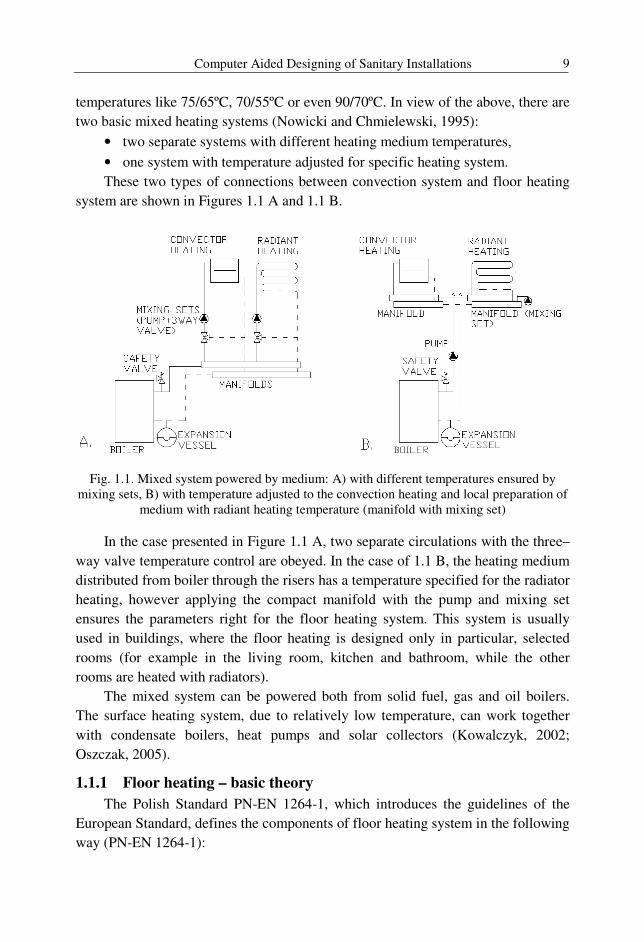
temperatures like 75/65ºC, 70/55ºC or even 90/70ºC. In view of the above, there are
two basic mixed heating systems (Nowicki and Chmielewski, 1995):
• two separate systems with different heating medium temperatures,
• one system with temperature adjusted for specific heating system.
These two types of connections between convection system and floor heating
system are shown in Figures 1.1 A and 1.1 B.
Fig. 1.1. Mixed system powered by medium: A) with different temperatures ensured by mixing sets, B) with temperature adjusted to the convection heating and local preparation of
medium with radiant heating temperature (manifold with mixing set)
In the case presented in Figure 1.1 A, two separate circulations with the three–
way valve temperature control are obeyed. In the case of 1.1 B, the heating medium
distributed from boiler through the risers has a temperature specified for the radiator
heating, however applying the compact manifold with the pump and mixing set
ensures the parameters right for the floor heating system. This system is usually
used in buildings, where the floor heating is designed only in particular, selected
rooms (for example in the living room, kitchen and bathroom, while the other
rooms are heated with radiators).
The mixed system can be powered both from solid fuel, gas and oil boilers.
The surface heating system, due to relatively low temperature, can work together
with condensate boilers, heat pumps and solar collectors (Kowalczyk, 2002;
Oszczak, 2005).
1.1.1 Floor heating – basic theory
The Polish Standard PN-EN 1264-1, which introduces the guidelines of the
European Standard, defines the components of floor heating system in the following
way (PN-EN 1264-1):
A. Żelazna, Z. Suchorab 10
• “Floor heating system – installation consisting of floor heating, heating
circuit distributors and control equipment.
• Floor heating – surface heating system, where pipes carrying water with or
without additives as a heating medium are laid in the floor.
• Heating circuit – section of floor heating connected to a heating circuit dis-
tributor which can be independently switched and controlled.
• Heating circuit distributor – common connection point for several heating
circuits.
• Heating floor area – area of the floor covered by the heating system be-
tween the outer pipes respectively the outer edges of the system with the
addition of a strip whose width is equal to half the pipe spacing but not ex-
ceeding 0.15 m.
• Peripheral area – floor surface which is heated to a higher temperature
and is generally an area of 1 m maximum in width along exterior walls. It
is not an occupied area.
• Residence area – part of heating floor designed for longer stay.”
The basic feature of surface heating is the fact, that it delivers heat to the room
mainly by radiation process (70% of the heat), therefore it is called radiant heating.
This results in less intensity of convection currents, characteristic for the traditional
radiator heating and moreover in very uniform temperature layout. Due to the limi-
tation of supply temperature for surface heating system, temperature differences in
heating room are smaller, so air movements are slighter. In comparison to the radia-
tors as heating elements, it offers very hygienic conditions due to limitation of dust
move and a lower air ionization (Kwiatkowski and Cholewa, 1980).
Typical floor heater is made as a heating circuit embedded in the screed. The
Standard (PN-EN 1264-1) lists A, B and C floor heating types, differing location of
heating pipes. The A-type refers to the floor heating with heating circuit embedded
in the cement screed. The B-type refers to the system with heating pipes partially
laid in the thermal insulation layer, while the C-type means heating circuit totally
dipped in the leveling layer
The transfer of heat takes place initially by conduction between the heating
medium and the pipe wall, across the screed and floor covering. Due to heating pipe
spacing, floor temperature is not homogenous. Therefore, for the sake of calcula-
tions simplification, the term: average heating floor surface temperature was intro-
duced, which is a resultant of temperatures in warmest (over pipes) and coolest (in
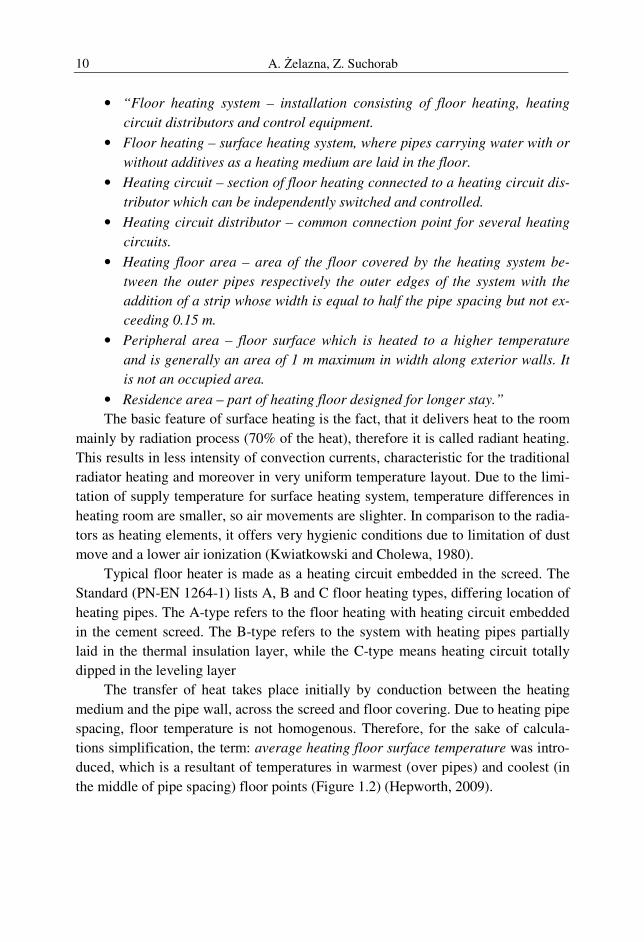
the middle of pipe spacing) floor points (Figure 1.2) (Hepworth, 2009).
Computer Aided Designing of Sanitary Installations 11
Fig. 1.2. Heating floor surface temperature layout
The heating floor temperature is specified by thermal comfort requirements
(Maier and Tejchman, 2006) and it may amount between 25ºC and 35ºC (Kwiat-
kowski and Cholewa, 1978; Nantka, 2006; Rosiński and Spik, 2009). Vertical tem-
perature distribution in a room heated by heating floor is highly similar to the per-
fect one, which provides thermal comfort conditions. This also results in the
posibility of an average internal room temperature reduction for even about 2ºC,
with thermal comfort requirements fulfilled. This relationship allows to reduce the
costs of heating in winter season, due to the lower supply temperature required.
Decrease of heating costs may even reach the amount of 10% during the heating
season (Hepworth, 2009).
The stream of heat transfered into the room depends on (Hepworth, 2009):
• heating medium temperature,
• pipes embed depth,
• pipe spacing,
• indoor room temperature.
Due to slight differences between the heating floor temperature and indoor
temperature, heating floor systems have a self-regulation ability. This process is
connected with the decrease in the density of heat flow into the room as a result of
rising room temperature and decreased temperature difference.
1.1.2 Structure of heating floor
Heating floor is an area of the floor, covered by the heating circuits, according
to the definition contained in (PN-EN 1264-1). The main element is heating circuit,
that delivers heating medium to the room. Due to pipe spacing in heating circuit,
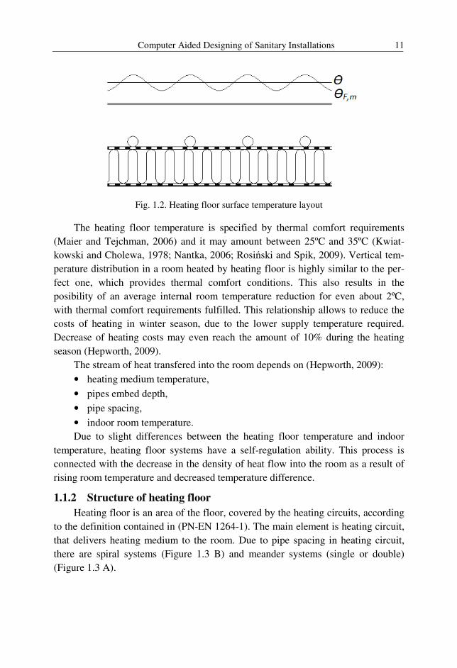
there are spiral systems (Figure 1.3 B) and meander systems (single or double)
(Figure 1.3 A).
A. Żelazna, Z. Suchorab 12
A. B.
Fig. 1.3. A) Pattern of the heating circuit in meander form with peripherial area, B) Pattern of the heating circuit in spiral form
The heating pipes spacing pattern has an effect on temperature layout in the
room. Spiral system, more difficult in execution, causes more uniform temperature
distribution, due to the fact that the supply and return pipes are parallel on the entire
surface of the room. In case of meander system, heating floor temperature
distribution is inhomogeneous. Characteristic for this system, irregular temperature
distribution (temperature drop along the heating medium flow direction) can be
used to compensate the increased loss in a specific parts of the room.
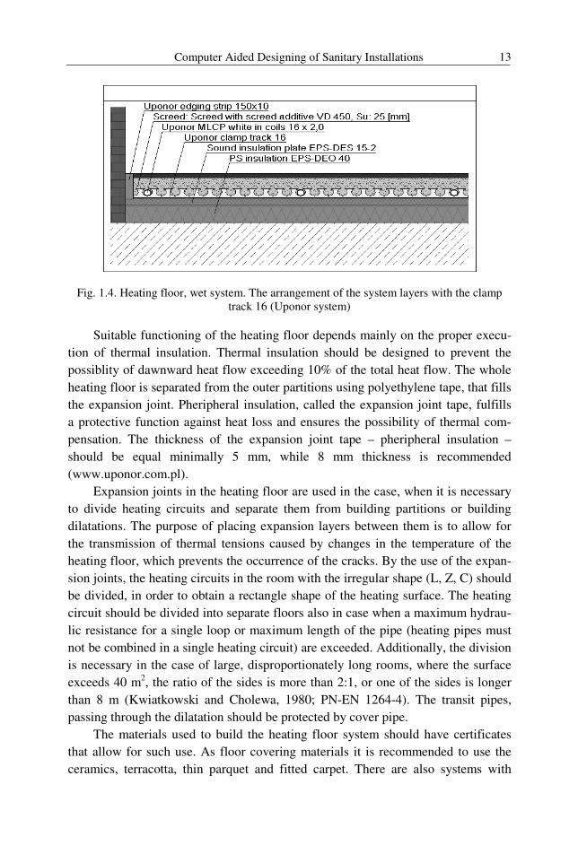
Aiming at compensation of the increased heat loss caused by the external win-
dows, the peripheral area can be applied. The peripheral area is a part of the heating
floor, or distinct heating circuit with pipe spacing smaller than the standard used in
the room. Heating pipe spacing in the peripheral area is usually between 10 and
15 cm, while in residence zone it is 20 to 35 and even 40 cm. The peripheral area
covers the surface of maximum 1 m in width along external wall with window.
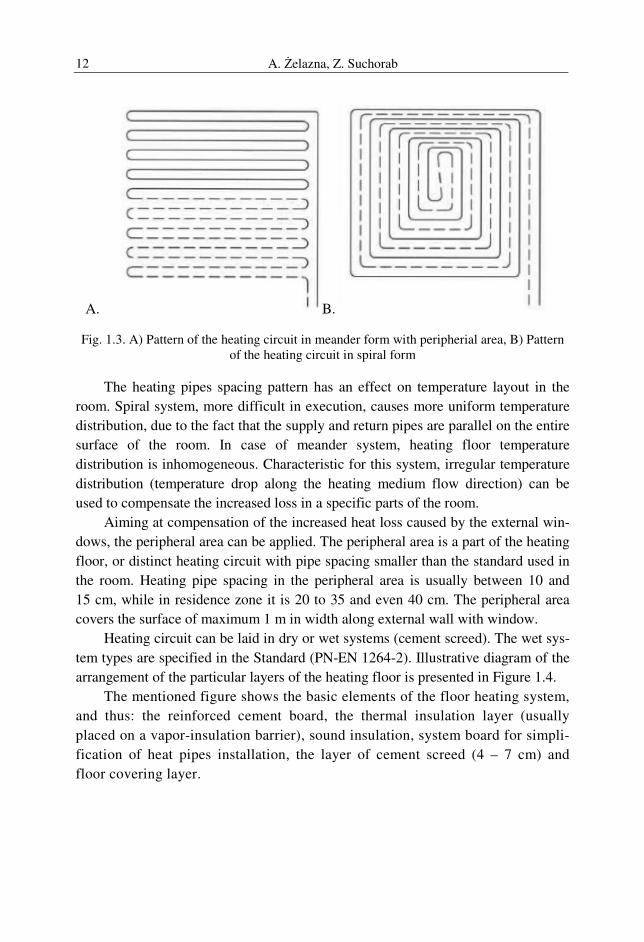
Heating circuit can be laid in dry or wet systems (cement screed). The wet sys-
tem types are specified in the Standard (PN-EN 1264-2). Illustrative diagram of the
arrangement of the particular layers of the heating floor is presented in Figure 1.4.
The mentioned figure shows the basic elements of the floor heating system,
and thus: the reinforced cement board, the thermal insulation layer (usually
placed on a vapor-insulation barrier), sound insulation, system board for simpli-
fication of heat pipes installation, the layer of cement screed (4 – 7 cm) and
floor covering layer.
Computer Aided Designing of Sanitary Installations 13
Fig. 1.4. Heating floor, wet system. The arrangement of the system layers with the clamp track 16 (Uponor system)
Suitable functioning of the heating floor depends mainly on the proper execu-
tion of thermal insulation. Thermal insulation should be designed to prevent the
possiblity of dawnward heat flow exceeding 10% of the total heat flow. The whole
heating floor is separated from the outer partitions using polyethylene tape, that fills
the expansion joint. Pheripheral insulation, called the expansion joint tape, fulfills
a protective function against heat loss and ensures the possibility of thermal com-
pensation. The thickness of the expansion joint tape – pheripheral insulation –
should be equal minimally 5 mm, while 8 mm thickness is recommended
(www.uponor.com.pl).
Expansion joints in the heating floor are used in the case, when it is necessary
to divide heating circuits and separate them from building partitions or building
dilatations. The purpose of placing expansion layers between them is to allow for
the transmission of thermal tensions caused by changes in the temperature of the
heating floor, which prevents the occurrence of the cracks. By the use of the expan-
sion joints, the heating circuits in the room with the irregular shape (L, Z, C) should
be divided, in order to obtain a rectangle shape of the heating surface. The heating
circuit should be divided into separate floors also in case when a maximum hydrau-
lic resistance for a single loop or maximum length of the pipe (heating pipes must
not be combined in a single heating circuit) are exceeded. Additionally, the division
is necessary in the case of large, disproportionately long rooms, where the surface
exceeds 40 m2, the ratio of the sides is more than 2:1, or one of the sides is longer
than 8 m (Kwiatkowski and Cholewa, 1980; PN-EN 1264-4). The transit pipes,
passing through the dilatation should be protected by cover pipe.
The materials used to build the heating floor system should have certificates
that allow for such use. As floor covering materials it is recommended to use the
ceramics, terracotta, thin parquet and fitted carpet. There are also systems with
A. Żelazna, Z. Suchorab 14
smaller pipes diameters and low supply temperatures, which are allowed to be used
under the panels.
1.1.3 Requirements for systems components
In accordance to the requirements set out in the standard (PN-EN 1264-3),
there is a limitation of an average temperature of floor surface in heating floor sys-
tems. The most favorable temperature range is between 24 and 26°C, while it must
not exceed 29°C. Due to the thermal comfort, the average floor surface temperature
should not exceed (Nowicki and Chmielewski, 1995):
• 29°C – in residential area (residential rooms and offices),
• 35°C – in peripheral area (with the outer building walls),
• 33°C – in bathrooms,
• 27°C – in work rooms, where workers stand up.
Due to above presented rules, there is also a limitation for the maximum supply
temperature. Allowable supply temperature is 55°C with the temperature difference
between 5 and 10 K.
Because of the maximum allowed hydraulic resistance of the single heating
circuit equal to 20 kPa, the value of water flow velocity in heating pipes should be
in the range between 0.1 ÷ 0.6 m/s and the maximum length of a single loop equals
120 m (for multilayer pipes 16×2mm).
The efficiency of heat transfer to the room should not be less than 90%, while
the downward heat transfer should not exceed 10%. Heat conduction resistance of
the finishing layers should not exceed 0.15 m2 K/W, and the resistance of the layers
below the heating pipes should not be less than 1.5 m2K/W. The average heat effi-
ciency of 1 m2 of the floor should be equal to about 80 W/m2 (Nantka, 2006).
The peripheral areas constituting more than 20% of the room surface or
exceeding 6 m2 should be built as separate circuits, usually with the temperature
difference 6 K. In the other case, a peripheral area, integrated with residence area
can be designed with temperature difference 10K (Nowicki and Chmielewski, 1995;
www.kisan.pl).
Manifolds used in the surface heating system should supply particular apart-
ments at each floor. Each manifold is equipped with check valves and control
valves for pressure equalization in the particular circuits. Control valves are in-
stalled on the return pipe. Manifolds set includes additionally shutoff valves and air
bleeders. Floor heating manifold are installed in the central part of the apartment
(e.g. hall, cleaning room) in concealed or on-wall cabinet (Nantka, 2006).
Heating floor effective surface should be estimated taking into account the
floor area free of furniture, particularly kitchen furniture and bookcases. Anyhow,
in some circumstances it is allowed to put pipes below the furniture and sanitary
equipment on the request of the investor.
Computer Aided Designing of Sanitary Installations 15
1.1.4 Designing of floor heating systems
Floor heating system should be taken into account at the design stage of the
building investment, due to the special requirements for insulation properties of the
partitions. The basics for the selection of heating floor are the calculations of the
design heat load of rooms made according to the PN-EN 12831:2006 Standard,
room dimensions and its shape. It is also necessary to establish the type of the floor
covering at the design stage, due to the thermal resistance requirements.
The value of heat flow density can be calculated using below presented formu-
la (www.kisan.pl):
F
Qq H
des = (1.1)
qdes – designed heat flow density [W/m2],
QH – design thermal output of floor heated room [W],
F – heating floor surface [m2].
Initial calculations ought to be conducted for the accommodation space with
the greatest specific thermal output value. With the assumed supply and return tem-
peratures and the internal room temperature, the average arithmetic temperature
difference can be calculated (www.kisan.pl):
i
rs
av θθθ
θ −+
=∆2
(1.2.)
∆θav – average arithmetic temperature difference between heating medium and
room temperature [K],
θs – supply medium temperature [°C],
θr – return medium temperature [°C],
θi – internal room temperature [°C].
Using producers guidelines it is possible to match pipelines spacing, when
q ≅ qdes condition is fulfilled and the acceptable floor temperature is not exceeded.
Basing on covering layer thermal resistance, the average arithmetic temperature
difference and specific thermal output, it is possible to match pipelines spacing.
Thermal output per 1 m of a pipe can be calculated using the below equation
(www.kisan.pl):
aqql ⋅= (1.3.)
ql – thermal output per 1 m of a pipe of heating circuit [W/m2],
q – specific thermal output, read from tables [W/m2],
a – pipes spacing [m],
The required length of the heating circuit is then calculated as (www.kisan.pl):
A. Żelazna, Z. Suchorab 16
l
H
q
Ql = (1.4.)
l – heating circuit length [m],
QH – design thermal output of floor heated room [W],
ql – thermal output per 1 m of a pipe of heating circuit [W/m2].
If the length of the circuit exceeds 120 m (Ø16 mm), it should be divided into
several circuits, for which separate heating and hydraulic calculations should be
carried out. Supply temperature for heating circuit connected in parallel is the same.
After drawing the heating circuit in a room, the mass flow of the heating medi-
um and the pressure drop caused by water flow through the circuit should be calcu-
lated, checking the condition of ∆p < 20 kPa. In case of exceeded 20 kPa of pres-
sure loss, the heating circuit should be divided and the calculations for each part
should be repeated.
Specific guidelines concerning the heating and hydraulic calculations and di-
mensioning of heating floor pipes are included in the standards (PN-EN 1264-1,
PN-EN 1264-2, PN-EN 1264-3, PN-EN 1264-4; www.kisan.pl).
1.2 Water supply systems in single-family buildings
1.2.1 Water supply systems – basic theory
Together with central heating, water supply systems are basic installations used
in almost all buildings. Water supplying the internal systems is delivered from the
water distribution networks or from individual water intakes. They are the compli-
cated systems containing many elements like water intake, pump stations, water
treatment plants, reservoirs, which are out of scope of this monograph and will not
be discussed here.
This sub-chapter is devoted to indoor water supply systems and the regulations
determining their designing, building and finally operation. According to
(Chudzicki and Sosnowski, 2011) there are more than 20 documents (regulations
and depositions) forming the rules of water supply systems designing and exploita-
tion. Among them, there are the Acts of Parliament and Regulations of Polish Min-
isters. Morover, in designing practice there are commonly used Polish Standards,
guidelines and technical literature.
The most important documents determining the methodology and rules of wa-
ter supply systems designing are the following:
• Regulation of the Polish Minister of Infrastructure dated 12 April 2002 on
technical requirements which have to be met by buildings and their
situation (Journal of Laws - Dz. U. Nr 75, item 690 with subsequent
amendments),

Computer Aided Designing of Sanitary Installations 17
• Polish Standard PN-92/B-01706, Installations for water supply. Design
(canceled without replacement).
• European Standard PN-EN 806-3:2006 – Specifications for installations in-
side buildings conveying water for human consumption – Part 3: Pipe siz-
ing – Simplified method .
1.2.2 Structure of water supply systems
According to above mentioned Polish Standard PN-92/B-01706 the most im-
portant elements of water supply system are:
Water supply installation – system of elements providing water supply in
building object and its surrounding, working as a whole system.
Hot water system – part of water supply installation used for hot water produc-
tion and its delivery to the draw-off points.
Water connection – pipeline connecting water source (water distribution
network or individual water intake) with indoor system.
Draw-off point (point of use)– point of water consumption.
Available pressure – hydraulic pressure at the point of water supply source in
computational conditions.
Central domestic hot water system – hot water system where hot water is
produced in boiler room.
Individual domestic hot water system – hot water system with hot water pro-
duction for one or a few draw-off points set in common room.
The most important elements of water supply systems are:
• pipes of cold, hot and circulation systems,
• pumps or pumping stations,
• fittings (stop valves, non-return valves, backflow preventers, regulation
valves, air bleeders, pressure meters, temperature meters, filters)
• water meters,
• water heaters, hot water storage tanks,
• mixers, taps and other types of draw-off points,
• manifolds,
• etc.
In general, each water supply system starts in bottom floor (basement or the
groundfloor) after the building entrance, at main valve of the water meter set. It
consists of the horizontal water pipelines and the vertical risers presented in Figure
1.5, delivering water to the particular floors by the branches, delivering medium to
the particular draw-off points (Sosnowski, 2000).
A. Żelazna, Z. Suchorab 18
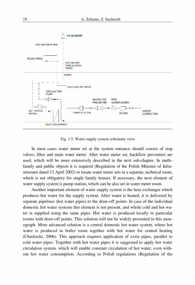
Fig. 1.5. Water supply system schematic view
In most cases water meter set at the system entrance should consist of stop
valves, filter and main water meter. After water meter set, backflow preventers are
used, which will be more extensively described in the next sub-chapter. In multi-
family and public objects it is required (Regulation of the Polish Minister of Infra-
structure dated 12 April 2002) to locate water meter sets in a separate, technical room,
which is not obligatory for single family houses. If necessary, the next element of
water supply system is pump station, which can be also set in water meter room.
Another important element of water supply system is the heat exchanger which
produces hot water for the supply system. After water is heated, it is delivered by
separate pipelines (hot water pipes) to the draw-off points. In case of the individual
domestic hot water systems this element is not present, and whole cold and hot wa-
ter is supplied using the same pipes. Hot water is produced locally in particular
rooms with draw-off points. This solution will not be widely presented in this mon-
ograph. More advanced solution is a central domestic hot water system, where hot
water is produced in boiler room together with hot water for central heating
(Chudzicki, 2006). This approach requires application of extra pipes, parallel to
cold water pipes. Together with hot water pipes it is suggested to apply hot water
circulation system, which will enable constant circulation of hot water, even with-
out hot water consumption. According to Polish regulations (Regulation of the

Computer Aided Designing of Sanitary Installations 19
Polish Minister of Infrastructure dated 12 April 2002) it is allowed not to use hot
water circulation in single family houses or in situations where total pipes capacity
is lower than 3 dm3, anyhow it is strongly recommended to apply this solution due
to bacteriological protection and hot water system efficiency (Chudzicki, 2012).
Depending on water distribution, the following systems are used
(Antonowicz, 1976):
• bottom water distribution (most often applied in new systems, with water
flow towards upwards direction; the advantage of this solution is good air
prevention by draw-of points at highest floor),
• upper water distribution (with water reservoirs, not used in single family
houses, with water flow downwards),
• ring water supply system (the most inevitable system, delivering water from
many directions, anyhow not applied in single family houses).
Another important division of water supply topology is division into
(Chudzicki and Sosnowski, 2011): one zone water supply system (in lower build-
ings), two- and more-zones water supply system (applied for higher buildings with
available pressure not enough to provide water delivery to the higher floors, not
applied in single family buildings).
To the particular floors of single-family or multi-family buildings water is de-
livered by vertical pipelines called risers (Figure 1.5) and there by tees or manifolds
is delivered to the flats or particular rooms. In case of multifamily buildings there
are also water meters applied for cold and hot water (Figure 1.5).
Similarly to central heating systems, water supply system pipes are made of
galvanized steel, copper and plastic. The most important information about pipes
and other materials are presented in the following monographs: (Gassner, 2008;
Chudzicki, Sosnowski, 2011; Panas, 2011).
1.2.3 Designing of water supply systems
Designing of water supply system ought to be conducted basing on the re-
quirements and regulations presented in the 1.2.1. sub-chapter of this monograph.
According to them, the maximum pressure in water supply system should not
exceed 0.6 MPa (60 mH2O) and should not be lower than 0.05 MPa (5 mH2O)
which means that in case of too high available pressure it is necessary to reduce it
using the suitable fittings. On the other hand it may be necessary to apply pump
stations to rise it, in case of too low pressure in the highest draw-off points.
According to (Chudzicki and Sosnowski, 2011) solution of water supply sys-
tem depends on object type and investor requirements. From the point of view of
this monograph, the most important are residential, single family buildings. Sanitary
equipment for all buildings type is precisely determined in the following mono-
graph (Chudzicki and Sosnowski, 2009).
A. Żelazna, Z. Suchorab 20
In general, designing of water supply system is divided into the following parts
(Chudzicki and Sosnowski, 2011):
• establishing water supply connection and positioning the main valve with
water meter set,
• positioning of draw-off points, boilers, etc.,
• guiding the pipelines,
• hydraulic calculations (water flow in particular system sectors, hydraulic
resistance and pipes dimensions) of cold water, hot water and, if necessary,
hot water circulation,
• matching the necessary fittings: backflow preventers, pressure limiting
valves, water meters etc.,
• calculating the minimal available pressure for the whole system and match-
ing the suitable pump station if necessary.
For efficient system functioning it is required to calculate the suitable dimen-
sions of pipes and calculate the minimal pressure available. According to the Polish
Standard PN-92/B-01706 it is divided into the particular stages:
• division of the whole system into the particular calculation sectors,
• determination of computational flows for the particular sectors,
• matching the pipes dimension for the particular sectors,
• determination of hydraulic resistance,
• determination of minimal pressure available for the whole water supply
system.
The most significant parameter for hydraulic calculations is computational wa-
ter flow. While this monograph is elaborated, Polish Standard PN-92/B-01706,
which is more than 20 years old and sometimes not adequate according to new liv-
ing standards etc., is still applied and procedures presented in this regulation are still
obeyed. In this document, the most significant parameters are: computational water
flow and normative outflow from the draw-off points. Normative outflow (qn) val-
ues are listed in the Table 1.1 of the discussed Polish Standard. They are expressed
in dm3/s and are characteristic for the particular types of draw-off points, which
means that normative outflow values differ for taps, mixers, hose connections,
shower heads, toilet flush tanks or urinal bowl flush pipes.
For hydraulic calculations computational flow is the most important and de-
pends on the following factors:
• object type (residential, office, administrative, hotels etc.),
• the sum of normative outflows (Σqn) [dm3/s].
Computer Aided Designing of Sanitary Installations 21
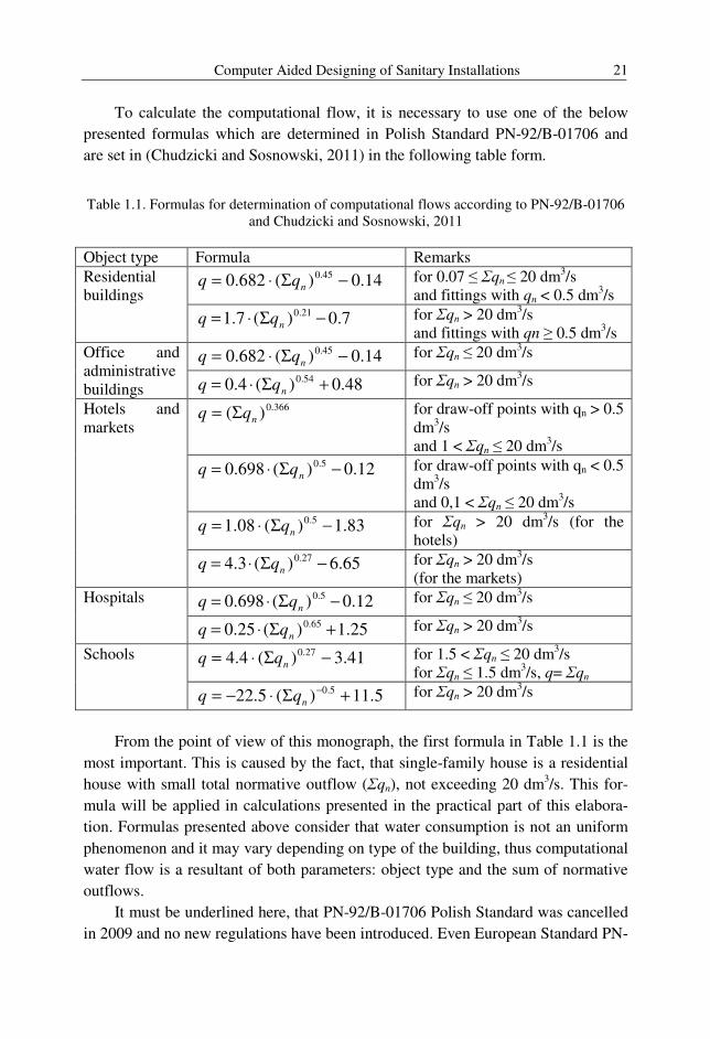
To calculate the computational flow, it is necessary to use one of the below
presented formulas which are determined in Polish Standard PN-92/B-01706 and
are set in (Chudzicki and Sosnowski, 2011) in the following table form.
Table 1.1. Formulas for determination of computational flows according to PN-92/B-01706 and Chudzicki and Sosnowski, 2011
Object type Formula Remarks
Residential buildings
14.0)(682.0 45.0 −Σ⋅= nqq for 0.07 ≤ Σqn ≤ 20 dm3/s and fittings with qn < 0.5 dm3/s
7.0)(7.1 21.0 −Σ⋅= nqq for Σqn > 20 dm3/s and fittings with qn ≥ 0.5 dm3/s
Office and administrative buildings
14.0)(682.0 45.0 −Σ⋅= nqq for Σqn ≤ 20 dm3/s
48.0)(4.0 54.0 +Σ⋅= nqq for Σqn > 20 dm3/s
Hotels and markets
366.0)( nqq Σ= for draw-off points with qn > 0.5 dm3/s and 1 < Σqn ≤ 20 dm3/s
12.0)(698.0 5.0 −Σ⋅= nqq for draw-off points with qn < 0.5 dm3/s and 0,1 < Σqn ≤ 20 dm3/s
83.1)(08.1 5.0 −Σ⋅= nqq for Σqn > 20 dm3/s (for the hotels)
65.6)(3.4 27.0 −Σ⋅= nqq for Σqn > 20 dm3/s (for the markets)
Hospitals 12.0)(698.0 5.0 −Σ⋅= nqq for Σqn ≤ 20 dm3/s
25.1)(25.0 65.0 +Σ⋅= nqq for Σqn > 20 dm3/s
Schools 41.3)(4.4 27.0 −Σ⋅= nqq for 1.5 < Σqn ≤ 20 dm3/s for Σqn ≤ 1.5 dm3/s, q= Σqn
5.11)(5.22 5.0 +Σ⋅−= −nqq for Σqn > 20 dm3/s
From the point of view of this monograph, the first formula in Table 1.1 is the
most important. This is caused by the fact, that single-family house is a residential
house with small total normative outflow (Σqn), not exceeding 20 dm3/s. This for-
mula will be applied in calculations presented in the practical part of this elabora-
tion. Formulas presented above consider that water consumption is not an uniform
phenomenon and it may vary depending on type of the building, thus computational
water flow is a resultant of both parameters: object type and the sum of normative
outflows.
It must be underlined here, that PN-92/B-01706 Polish Standard was cancelled
in 2009 and no new regulations have been introduced. Even European Standard PN-
A. Żelazna, Z. Suchorab 22
EN 806-3:2006 introduced in 2006 is not always applicable in designing of more
complicable systems (Jeżowiecki and Nowakowski, 2011). According to its title,
this regulation suggests to use a simplified method of pipes dimensions calculating,
using load units (LU) depending on draw-off points types. Anyhow, the authors of
this book decided to discuss PN-92/B-01706 Polish Standard, being still in common
use. Also described in the third chapter CAD tool (Instal-San T) applies that stand-
ard for calculations.
One of the most important hydraulic parameters is water velocity in pipes,
which, according to PN-92/B-01706, should not exceed:
• 1.5 m/s in sectors between the raisers and draw-off points,
• 1.5 m/s in the raisers,
• 1.0 m/s in the distribution pipelines,
• 1.0 m/s in the water source connections.
It must be explained, that above presented maximum velocities are suggested
for steel pipes. In case of using of other pipelines types or materials it is suggested
to follow the producers instructions. In general it can be assumed that for plastic
pipes, maximum velocities can be increased for about 0.5 m/s comparing to steel
ones, anyhow it is suggested to verify this in above mentioned instructions.
Hydraulic resistance is the resultant of the following flow parameters:
• computational water flow,
• water velocity,
• pipeline dimension.
Thus, with this parameters it is possible to determine pressure loss in particular
sectors of the pipeline system.
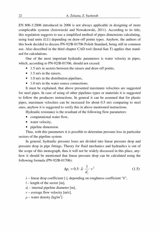
In general, hydraulic pressure loses are divided into linear pressure drop and
pressure drop in pipe fittings. Theory for fluid mechanics and hydraulics is out of
the scope of this monograph, thus it will not be widely discussed in this place, any-
how it should be mentioned that linear pressure drop can be calculated using the
following formula (PN-92/B-01706):
215.0 v
dp
i
l ⋅⋅⋅=∆ λ (1.5)
λ – linear drop coefficient [-], depending on roughness coefficient “k”,
l – length of the sector [m],
di – internal pipeline diameter [m],
v – average flow velocity [m/s],
ρ – water density [kg/m3].
Computer Aided Designing of Sanitary Installations 23
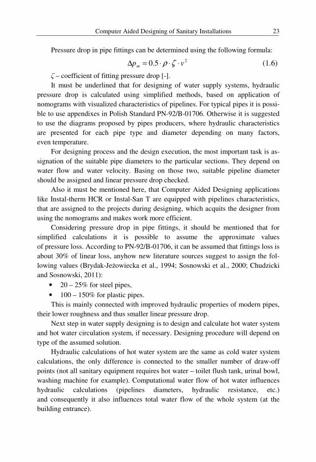
Pressure drop in pipe fittings can be determined using the following formula:
25.0 vpm ⋅⋅⋅=∆ ζρ (1.6)
ζ – coefficient of fitting pressure drop [-].
It must be underlined that for designing of water supply systems, hydraulic
pressure drop is calculated using simplified methods, based on application of
nomograms with visualized characteristics of pipelines. For typical pipes it is possi-
ble to use appendixes in Polish Standard PN-92/B-01706. Otherwise it is suggested
to use the diagrams proposed by pipes producers, where hydraulic characteristics
are presented for each pipe type and diameter depending on many factors,
even temperature.
For designing process and the design execution, the most important task is as-
signation of the suitable pipe diameters to the particular sections. They depend on
water flow and water velocity. Basing on those two, suitable pipeline diameter
should be assigned and linear pressure drop checked.
Also it must be mentioned here, that Computer Aided Designing applications
like Instal-therm HCR or Instal-San T are equipped with pipelines characteristics,
that are assigned to the projects during designing, which acquits the designer from
using the nomograms and makes work more efficient.
Considering pressure drop in pipe fittings, it should be mentioned that for
simplified calculations it is possible to assume the approximate values
of pressure loss. According to PN-92/B-01706, it can be assumed that fittings loss is
about 30% of linear loss, anyhow new literature sources suggest to assign the fol-
lowing values (Brydak-Jeżowiecka et al., 1994; Sosnowski et al., 2000; Chudzicki
and Sosnowski, 2011):
• 20 – 25% for steel pipes,
• 100 – 150% for plastic pipes.
This is mainly connected with improved hydraulic properties of modern pipes,
their lower roughness and thus smaller linear pressure drop.
Next step in water supply designing is to design and calculate hot water system
and hot water circulation system, if necessary. Designing procedure will depend on
type of the assumed solution.
Hydraulic calculations of hot water system are the same as cold water system
calculations, the only difference is connected to the smaller number of draw-off
points (not all sanitary equipment requires hot water – toilet flush tank, urinal bowl,
washing machine for example). Computational water flow of hot water influences
hydraulic calculations (pipelines diameters, hydraulic resistance, etc.)
and consequently it also influences total water flow of the whole system (at the
building entrance).
A. Żelazna, Z. Suchorab 24
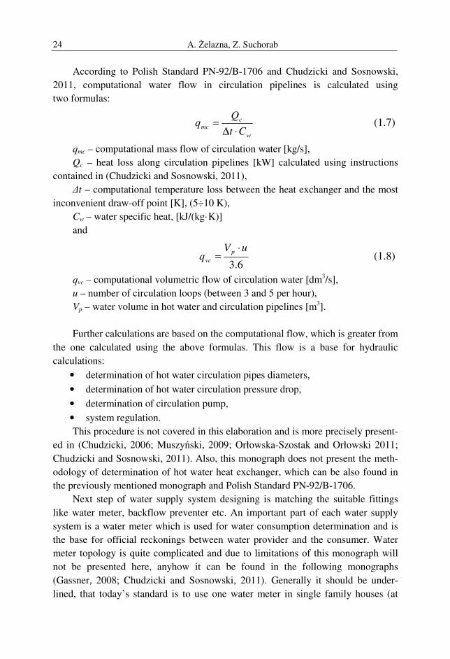
According to Polish Standard PN-92/B-1706 and Chudzicki and Sosnowski,
2011, computational water flow in circulation pipelines is calculated using
two formulas:
w
c
mcCt
⋅∆= (1.7)
qmc – computational mass flow of circulation water [kg/s],
Qc – heat loss along circulation pipelines [kW] calculated using instructions
contained in (Chudzicki and Sosnowski, 2011),
∆t – computational temperature loss between the heat exchanger and the most
inconvenient draw-off point [K], (5÷10 K),
Cw – water specific heat, [kJ/(kg·K)]
and
6.3
uVq
p
vc
⋅= (1.8)
qvc – computational volumetric flow of circulation water [dm3/s],
u – number of circulation loops (between 3 and 5 per hour),
Vp – water volume in hot water and circulation pipelines [m3].
Further calculations are based on the computational flow, which is greater from
the one calculated using the above formulas. This flow is a base for hydraulic
calculations:
• determination of hot water circulation pipes diameters,
• determination of hot water circulation pressure drop,
• determination of circulation pump,
• system regulation.
This procedure is not covered in this elaboration and is more precisely present-
ed in (Chudzicki, 2006; Muszyński, 2009; Orłowska-Szostak and Orłowski 2011;
Chudzicki and Sosnowski, 2011). Also, this monograph does not present the meth-
odology of determination of hot water heat exchanger, which can be also found in
the previously mentioned monograph and Polish Standard PN-92/B-1706.
Next step of water supply system designing is matching the suitable fittings
like water meter, backflow preventer etc. An important part of each water supply
system is a water meter which is used for water consumption determination and is
the base for official reckonings between water provider and the consumer. Water
meter topology is quite complicated and due to limitations of this monograph will
not be presented here, anyhow it can be found in the following monographs
(Gassner, 2008; Chudzicki and Sosnowski, 2011). Generally it should be under-
lined, that today’s standard is to use one water meter in single family houses (at
Computer Aided Designing of Sanitary Installations 25
system entrance) and several water meters in multifamily houses – main water me-
ter at system entrance and small, apartment water meters divided into cold water
and hot water type.
Water meter determination is also standardized in PN-92/01706, which means
that does not match current standards of water consumption (Gwoździej-Mazur and
Tuz, 2002; Cholewa et al., 2009) and water meters selected with this method are
often overestimated, which in turn, may result in wrong readouts of water consump-
tion. Anyhow this Polish Standard has not been replaced by any official document
yet and this methodology is still valid and will be presented in this monograph.
Another attempts to the following task is presented in the following documents
(Orłowska-Szostak, 2011)
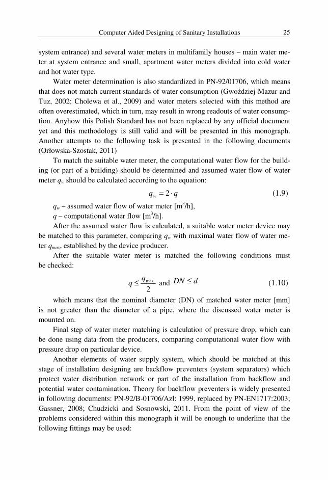
To match the suitable water meter, the computational water flow for the build-
ing (or part of a building) should be determined and assumed water flow of water
meter qw should be calculated according to the equation:
qqw ⋅= 2 (1.9)
qw – assumed water flow of water meter [m3/h],
q – computational water flow [m3/h].
After the assumed water flow is calculated, a suitable water meter device may
be matched to this parameter, comparing qw with maximal water flow of water me-
ter qmax, established by the device producer.
After the suitable water meter is matched the following conditions must
be checked:
2maxq
q ≤ and dDN ≤ (1.10)
which means that the nominal diameter (DN) of matched water meter [mm]
is not greater than the diameter of a pipe, where the discussed water meter is
mounted on.
Final step of water meter matching is calculation of pressure drop, which can
be done using data from the producers, comparing computational water flow with
pressure drop on particular device.
Another elements of water supply system, which should be matched at this
stage of installation designing are backflow preventers (system separators) which
protect water distribution network or part of the installation from backflow and
potential water contamination. Theory for backflow preventers is widely presented
in following documents: PN-92/B-01706/Azl: 1999, replaced by PN-EN1717:2003;
Gassner, 2008; Chudzicki and Sosnowski, 2011. From the point of view of the
problems considered within this monograph it will be enough to underline that the
following fittings may be used:
A. Żelazna, Z. Suchorab 26
• EA check vale backflow preventer – for domestic systems,
• BA backflow preventers – for increased requirements,
• HA system separators for hose connectors,
• GA system separators for Water Treatment Stations.
Matching of the proper backflow preventer is important due to water quality
protection, but it is also important for hydraulic calculations of minimal available
pressure. This is caused by high pressure drop on backflow preventers (especially
BA backflow preventers) which may strongly influence total pressure drop of the
water supply system (Skiba 2011; Widomski et al., 2011).
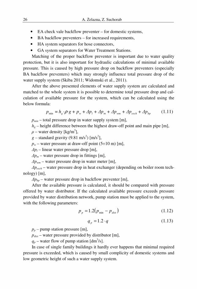
After the above presented elements of water supply system are calculated and
matched to the whole system it is possible to determine total pressure drop and cal-
culation of available pressure for the system, which can be calculated using the
below formula:
bpexchwmmlwg ∆p∆p∆p∆p∆ppghp + + + +++·· = min ρ (1.11)
pmin – total pressure drop in water supply system [m],
hg – height difference between the highest draw-off point and main pipe [m],
ρ – water density [kg/m3],
g – standard gravity (9.81 m/s2) [m/s2],
pw – water pressure at draw-off point (5÷10 m) [m],
∆pl – linear water pressure drop [m],
∆pm – water pressure drop in fittings [m],
∆pwm – water pressure drop in water meter [m],
∆pexch – water pressure drop in heat exchanger (depending on boiler room tech-
nology) [m], ∆pbp – water pressure drop in backflow preventer [m],
After the available pressure is calculated, it should be compared with pressure
offered by water distributor. If the calculated available pressure exceeds pressure
provided by water distribution network, pump station must be applied to the system,
with the following parameters:
( )distp ppp −= min2.1 (1.12)
qq p ⋅= 2.1 (1.13)
pp – pump station pressure [m],
pdist – water pressure provided by distributor [m],
qp – water flow of pump station [dm3/s].
In case of single family buildings it hardly ever happens that minimal required
pressure is exceeded, which is caused by small complicity of domestic systems and
low geometric height of such a water supply system.
Computer Aided Designing of Sanitary Installations 27
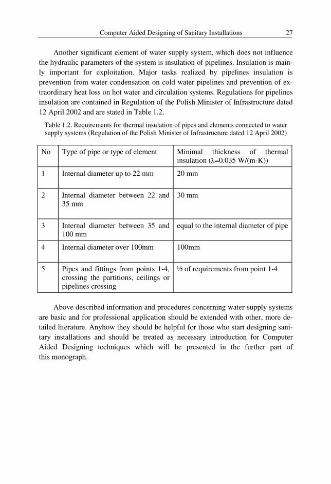
Another significant element of water supply system, which does not influence
the hydraulic parameters of the system is insulation of pipelines. Insulation is main-
ly important for exploitation. Major tasks realized by pipelines insulation is
prevention from water condensation on cold water pipelines and prevention of ex-
traordinary heat loss on hot water and circulation systems. Regulations for pipelines
insulation are contained in Regulation of the Polish Minister of Infrastructure dated
12 April 2002 and are stated in Table 1.2.
Table 1.2. Requirements for thermal insulation of pipes and elements connected to water supply systems (Regulation of the Polish Minister of Infrastructure dated 12 April 2002)
No Type of pipe or type of element
Minimal thickness of thermal insulation (λ=0.035 W/(m·K))
1
Internal diameter up to 22 mm
20 mm
2
Internal diameter between 22 and 35 mm
30 mm
3 Internal diameter between 35 and 100 mm
equal to the internal diameter of pipe
4 Internal diameter over 100mm 100mm
5 Pipes and fittings from points 1-4, crossing the partitions, ceilings or pipelines crossing
½ of requirements from point 1-4
Above described information and procedures concerning water supply systems
are basic and for professional application should be extended with other, more de-
tailed literature. Anyhow they should be helpful for those who start designing sani-
tary installations and should be treated as necessary introduction for Computer
Aided Designing techniques which will be presented in the further part of
this monograph.
A. Żelazna, Z. Suchorab 28
2 Description of the designing tool
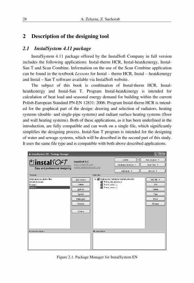
2.1 InstalSystem 4.11 package
InstalSystem 4.11 package offered by the InstalSoft Company in full version
includes the following applications: Instal-therm HCR, Instal-heat&energy, Instal-
San T and Scan Combine. Information on the use of the Scan Combine application
can be found in the textbook Lessons for Instal – therm HCR, Instal – heat&energy
and Instal – San T software available via InstalSoft website.
The subject of this book is combination of Instal-therm HCR, Instal-
heat&energy and Instal-San T. Program Instal-heat&energy is intended for
calculation of heat load and seasonal energy demand for building within the current
Polish-European Standard PN-EN 12831: 2006. Program Instal-therm HCR is intend-
ed for the graphical part of the design: drawing and selection of radiators, heating
systems (double- and single-pipe systems) and radiant surface heating systems (floor
and wall heating systems). Both of these applications, as it has been underlined in the
introduction, are fully compatible and can work on a single file, which significantly
simplifies the designing process. Instal-San T program is intended for the designing
of water and sewage systems, which will be described in the second part of this study.
It uses the same file type and is compatible with both above described applications.
Figure 2.1. Package Manager for InstalSystem EN
Computer Aided Designing of Sanitary Installations 29
The launch of InstalSystem package is executed by the Package Manager
(Figure 2.1). The Manager enables program activation by entering the required li-
cense, update and view of the available catalogues and support of service. New
projects are archived in the folder created in the Documents folder of user's com-
puter (this location is selected automatically, but it can be changed during installa-
tion). Files editing requires the launch of one of the applications included in the
package. Building and installation files of InstalSystem package have the extension
*.isb, and backup files – *.~ ib.
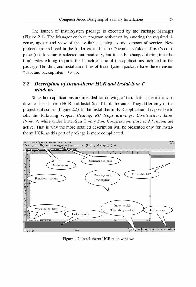
2.2 Description of Instal-therm HCR and Instal-San T
windows
Since both applications are intended for drawing of installation, the main win-
dows of Instal-therm HCR and Instal-San T look the same. They differ only in the
project edit scopes (Figure 2.2). In the Instal-therm HCR application it is possible to
edit the following scopes: Heating, RH loops drawings, Construction, Base,
Printout, while under Instal-San T only San, Construction, Base and Printout are
active. That is why the more detailed description will be presented only for Instal-
therm HCR, as this part of package is more complicated.
Figure 1.2. Instal-therm HCR main window
Functions toolbar
Main menu
Standard toolbars
Data table F12
Worksheets’ tabs
List of errors
Edit scopes
Drawing aids
(Operating modes)
Drawing area
(workspace)
A. Żelazna, Z. Suchorab 30
The main menu of Instal-therm HCR consists of the following fields: File,
Edit, Components, Modules, Component data, Options, View and Help. It is sug-
gested to check the functionality of each program feature by the user himself. Be-
low, there are the main component functions described:
File: except of the standard functions as opening, closing and saving the file, it
allows to start calculations, manage worksheets and import or export drawings.
Edit: it contains the basic Windows system functions like Copy, Paste, Delete,
but also a useful selection tool, which allows to select components of the particular
type (for example only radiators, walls or base, depending on the project
edit scope).
Components: this tab contains functions useful for installation drawing, like
automatic connection of elements, lock, flip, division, etc..
Modules: it is a useful option for installations drawing, where some recurrent
group of components can be saved as module and pasted in the necessary localiza-
tions.
Component data: it includes functions which allow to add room numbers au-
tomatically, check connections between elements and create the pairs of primary
and shadow elements.
Options: they contain Project options (F7) and catalogues database. Project
options are the significant part of designing and they will be described in the practi-
cal part of the book.
View: it contains zoom scales, as well as the toolbar options and other elements
visible in the window of program. Furthermore, it allows to show the critical hy-
draulic circuit.
Help: it contains the menu of help and connection with service website.
The next element that needs to be described is a Standard toolbar. This toolbar
is consisted of several tabs. There are two constant tabs: Program and Functions,
which are available under all the project scopes. Functions toolbar is visible all the
time at the left side of the window as a separate tool (Figure 1.2). A rest of the tabs
differ depending on the project scope. For example, in scope of Heating, there are
additionally Network / radiator, Radiant, Fittings, 2-pipe and 1-pipe tabs, including
elements of heating installation to be added to created drawing. Under RH loops
drawing, there is an additional tab called Radiant, where polylines for drawing the
circuits (automatically or manually) are situated. Under Construction edit scope,
Standard toolbar is additionally consisted of Elements tab, where the partitions of
building and other elements connected with its structure can be found. It should also
be mentioned, that the Standard toolbar can have different commands and icons in
the worksheet of schematic view, which will be described below.
Computer Aided Designing of Sanitary Installations 31
Worksheet tabs allow to move between different parts of the project of build-
ing. It is an important information because in Instal-therm HCR and Instal-San T
every storey of building has to be located in separate worksheet. In standard option,
we have two basic worksheets: Worksheet 1 and Worksheet 2, representing plan
view and schematic view of the installation respectively. Plan view aims in presen-
tation of storey, while schematic view is intended to show the developed view of
installation. Because of these differences, the editing of schematic view is possible
within the scopes of: Heating, San, Construction and Printout. The meaning of
commands included in the toolbars is also adjusted to this kind of drawing.
The workspace is enclosed on left–hand side and top by the rulers. These rulers
(horizontal and vertical) are intended to control the position of components of the
drawing. The button between the rulers enables changing the current scale. On the
opposite side of the workspace, there are sliders, again vertical and horizontal. They
are used to move the drawing area. In the corner between the sliders, there is the
navigator, which assists moving within the workspace.
The list of errors is necessary for the appropriate hydraulic calculations of the
installation. There are three types of basic statements:
errors – the most important messages, displayed in capital letters. All errors
that occur in project must be corrected; if not it will be impossible to achieve all
results of calculations,
warnings – the messages less important than errors. They do not block further
calculations. Warnings are usually connected with data or results that should
be checked,
hints – the messages aiming in reminding of some data or results. Hints do not
block further calculations.
To check where exactly the element with error is situated, it is necessary to
click on the chosen message. The wrong or suspicious element will be then under-
lined by yellow color.
Drawing aids called also operating mode fields are intended to facilitate the
drawing functions. They include:
ORTO – allows to draw only in horizontal or vertical position.
LOCK – locks the elements on drawing so that they cannot be moved.
GRID – allows to draw only with some specified distance.
AUTO – an automatic search and connection of components to the closest one.
REP – repeating of the selected command.
A. Żelazna, Z. Suchorab 32
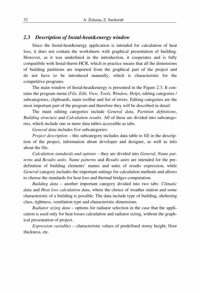
2.3 Description of Instal-heat&energy window
Since the Instal-heat&energy application is intended for calculation of heat
loss, it does not contain the worksheets with graphical presentation of building.
However, as it was underlined in the introduction, it cooperates and is fully
compatibile with Instal-therm HCR, which in practice means that all the dimensions
of building partitions are imported from the graphical part of the project and
do not have to be introduced manually, which is characteristic for the
competitive programs.
The main window of Instal-heat&energy is presented in the Figure 2.3. It con-
tains the program menu (File, Edit, View, Tools, Window, Help), editing categories /
subcategories, clipboards, main toolbar and list of errors. Editing categories are the
most important part of the program and therefore they will be described in detail.
The main editing categories include General data, Partition definitions,
Building structure and Calculation results. All of these are divided into subcatego-
ries, which include one or more data tables accessible as tabs.
General data includes five subcategories:
Project description – this subcategory includes data table to fill in the descrip-
tion of the project, information about developer and designer, as well as info
about the file.
Calculation standards and options – they are divided into General, Name pat-
terns and Results units. Name patterns and Results units are intended for the pre-
definition of building elements’ names and units of results expression, while
General category includes the important settings for calculation methods and allows
to choose the standards for heat loss and thermal bridges computation.
Building data – another important category divided into two tabs: Climatic
data and Heat loss calculation data, where the choice of weather station and some
characteristic of a building is possible. The data include type of building, sheltering
class, tightness, ventilation type and characteristic dimensions.
Radiator sizing data – options for radiator selection in the case that the appli-
cation is used only for heat losses calculation and radiator sizing, without the graph-
ical presentation of project.
Expression variables – characteristic values of predefined storey height, floor
thickness, etc.
Computer Aided Designing of Sanitary Installations 33
Figure 2.3. Fragment of the main window of Instal-heat&energy module
Partition definitions enable the calculation of heat transfer coefficient
U [W/m2K] by the use of building materials data library. Each partition of a build-
ing should be defined as consisted of individual materials, characterized by the den-
sity, specific heat, thermal conductivity (library data) and thickness of a layer (user
data). The mode of definition creation will be described in detail in the practical
part of this book.
Building structure includes the list of storeys, rooms and partitions and their
characteristics of the calculated building. It is an useful tool to check the correctness
of automatic computations (if the heat loss in the room is not calculated properly, it
will be marked as “???” and the mistake is easy to be found in the list of partitions).
In case when the project is only calculated in the Instal-heat&energy module, it
enables to count heat loss by the creation of new rooms with partitions of specified
dimensions and types defined in the Partition definitions.
Calculation results feature is intended to export the final results to the MS Ex-
cel file or to print them out directly from the program. The results are divided into
several categories (General data, Results for building, Room parameters, List of
heat losses in rooms, Room data and results, Data and results for partitions,
Partition list, List of heat losses through partitions, List of radiators in rooms, List
of radiators), which can be printed separately.

A. Żelazna, Z. Suchorab 34
3 Examplary design of sanitary sysems
In this chapter, two complete examples of installations designing in
InstalSystem package will be presented. The first case, described in section 3.1.,
concerns the heating installation designing, including design heat load calculation,
hydraulic computations and graphical part of project. In the second case, the atten-
tion was paid on the water supply system in the designed single-family building.
3.1 Project of central heating installation for the detached house
3.1.1 Creation of a new file
The first step of the designing in InstalSystem package is the use of Package
Manager. The main window of Package Manager is presented in Figure 3.1. It is
consisted of two main areas with the list of folders (left side) and the list of files
(right side of a window). Moreover, it includes the buttons for editing of the new
file or project (folder), as well as the buttons for update, activation, catalogues data-
base search and support. The installation and activation of the program is described
in the producer’s guidelines (www.instalsoft.com) and it will not be discussed here.
When the program is activated, it is necessary to start a new file. For the
organization purposes, it should be preceded by the creation of a New project,
which means the new folder with the new Instal Package file. By the use of New file
button, it is possible to create new Word, Excel, text or *.isb files. It is necessary to
enter a name of the file.
Figure 3.1. Fragment of the InstalSystem EN Package Manager window
Computer Aided Designing of Sanitary Installations 35
For the purpose of this book, a new project Detached house and a new file Pro-
ject 1 were created. The file will be base for further calculations both for heating
and water supply installations.
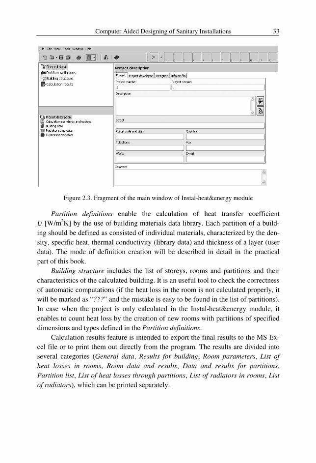
3.1.2 DWG base import to Instal-therm HCR
After opening the file Project 1 in Instal-therm HCR (by the use of right button
of a mouse) it is crucial to import AutoCAD base. There are two main ways of
DWG files import. In the case of detached houses it is easy to prepare the base for
automatic reading in the program, therefore the stage of base import in Instal-therm
HCR is short. However, the file needs to be specially prepared in AutoCAD (Figure
3.2). Firstly, all the main elements of building structure like walls, windows, doors
and other elements (ex. stairs) should be drawn in separate layers. Moreover, the
building should be placed in 0,0 point in AutoCAD coordinates’ system. Every
separate storey of building has to be placed in separate file, in the same point with
coordinates 0,0. The files should be saved as “ground_floor.dwg” and
“first_floor.dwg” in AutoCAD 2000 format.
Figure 3.2. DWG base prepared for import
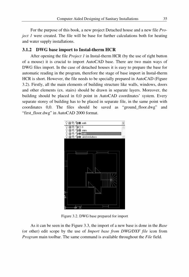
As it can be seen in the Figure 3.3, the import of a new base is done in the Base
(or other) edit scope by the use of Import base from DWG/DXF file icon from
Program main toolbar. The same command is available throughout the File field.
A. Żelazna, Z. Suchorab 36
Figure 3.3. The DWG base import – edit scope Base and command icon in Program toolbar
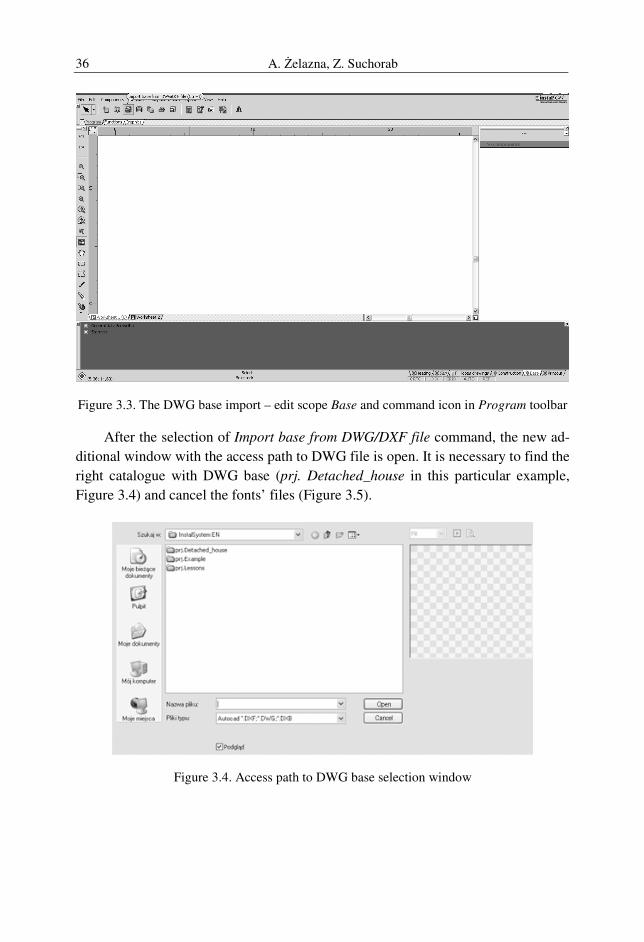
After the selection of Import base from DWG/DXF file command, the new ad-
ditional window with the access path to DWG file is open. It is necessary to find the
right catalogue with DWG base (prj. Detached_house in this particular example,
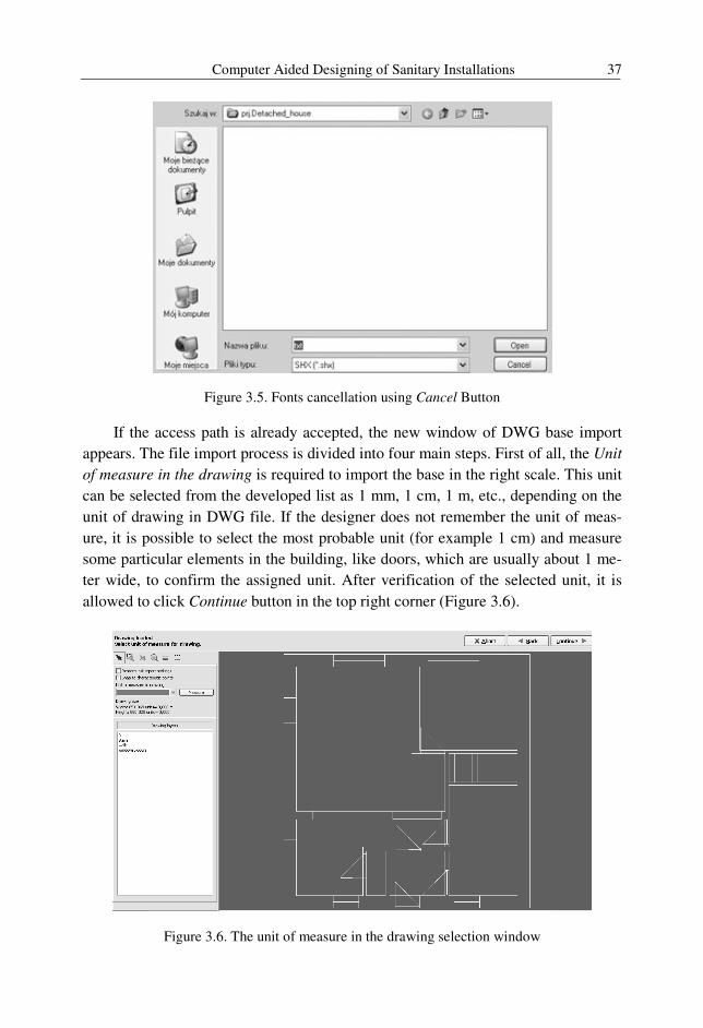
Figure 3.4) and cancel the fonts’ files (Figure 3.5).
Figure 3.4. Access path to DWG base selection window
Computer Aided Designing of Sanitary Installations 37
Figure 3.5. Fonts cancellation using Cancel Button
If the access path is already accepted, the new window of DWG base import
appears. The file import process is divided into four main steps. First of all, the Unit
of measure in the drawing is required to import the base in the right scale. This unit
can be selected from the developed list as 1 mm, 1 cm, 1 m, etc., depending on the
unit of drawing in DWG file. If the designer does not remember the unit of meas-
ure, it is possible to select the most probable unit (for example 1 cm) and measure
some particular elements in the building, like doors, which are usually about 1 me-
ter wide, to confirm the assigned unit. After verification of the selected unit, it is
allowed to click Continue button in the top right corner (Figure 3.6).
Figure 3.6. The unit of measure in the drawing selection window
A. Żelazna, Z. Suchorab 38
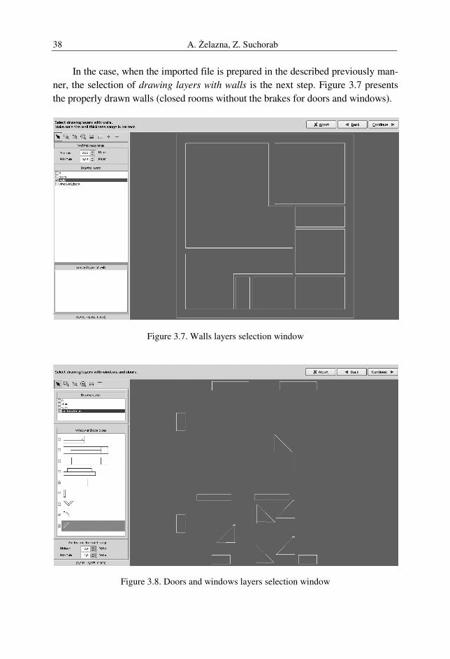
In the case, when the imported file is prepared in the described previously man-
ner, the selection of drawing layers with walls is the next step. Figure 3.7 presents
the properly drawn walls (closed rooms without the brakes for doors and windows).
Figure 3.7. Walls layers selection window
Figure 3.8. Doors and windows layers selection window
Computer Aided Designing of Sanitary Installations 39
It is crucial to remember about the thickness range of the walls which means
the distance between two lines that will be interpreted by the program as partition.
Continuation of import process means the selection of drawing layers with
windows and doors as the next step. Figure 3.8 presents the examples of properly
drawn windows and doors (recognized in program types). As well as the types se-
lection, it is necessary to remember about the width range of windows and doors.
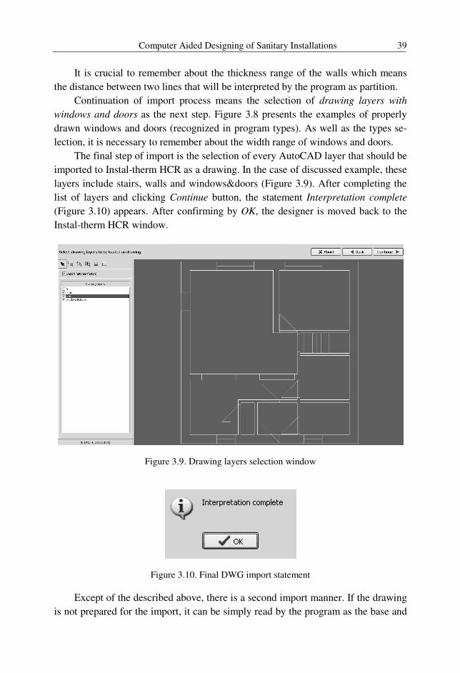
The final step of import is the selection of every AutoCAD layer that should be
imported to Instal-therm HCR as a drawing. In the case of discussed example, these
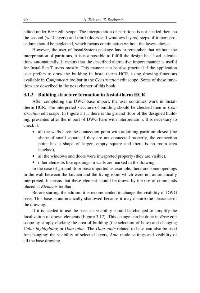
layers include stairs, walls and windows&doors (Figure 3.9). After completing the
list of layers and clicking Continue button, the statement Interpretation complete
(Figure 3.10) appears. After confirming by OK, the designer is moved back to the
Instal-therm HCR window.
Figure 3.9. Drawing layers selection window
Figure 3.10. Final DWG import statement
Except of the described above, there is a second import manner. If the drawing
is not prepared for the import, it can be simply read by the program as the base and
A. Żelazna, Z. Suchorab 40
edited under Base edit scope. The interpretation of partitions is not needed then, so
the second (wall layers) and third (doors and windows layers) steps of import pro-
cedure should be neglected, which means continuation without the layers choice.
However, the user of InstalSystem package has to remember that without the
interpretation of partitions, it is not possible to fulfill the design heat load calcula-
tions automatically. It means that the described alternative import manner is useful
for Instal-San T users mostly. This manner can be also practical if the application
user prefers to draw the building in Instal-therm HCR, using drawing functions
available in Components toolbar in the Construction edit scope. Some of these func-
tions are described in the next chapter of this book.
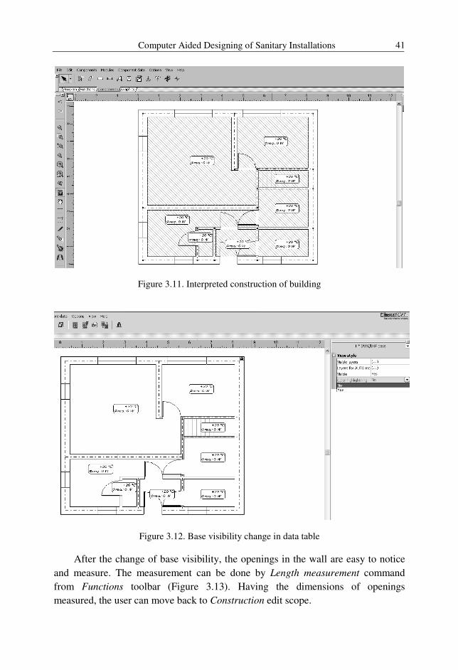
3.1.3 Building structure formation in Instal-therm HCR
After completing the DWG base import, the user continues work in Instal-
therm HCR. The interpreted structure of building should be checked then in Con-
struction edit scope. In Figure 3.11, there is the ground floor of the designed build-
ing, presented after the import of DWG base with interpretation. It is necessary to
check if:
• all the walls have the connection point with adjoining partition closed (the
shape of small square; if they are not connected properly, the connection
point has a shape of larger, empty square and there is no room area
hatched),
• all the windows and doors were interpreted properly (they are visible),
• other elements like openings in walls are marked in the drawing.
In the case of ground floor base imported as example, there are some openings
in the wall between the kitchen and the living room which were not automatically
interpreted. It means that these element should be drawn by the use of commands
placed at Elements toolbar.
Before starting the edition, it is recommended to change the visibility of DWG
base. This base is automatically shadowed because it may disturb the clearance of
the drawing.
If it is needed to use the base, its visibility should be changed to simplify the
localization of drawn elements (Figure 3.12). This change can be done in Base edit
scope by simply clicking the area of building (the selection of base) and changing
Color highlighting in Data table. The Data table related to base can also be used
for changing: the visibility of selected layers, Auto mode settings and visibility of
all the base drawing.
Computer Aided Designing of Sanitary Installations 41
Figure 3.11. Interpreted construction of building
Figure 3.12. Base visibility change in data table
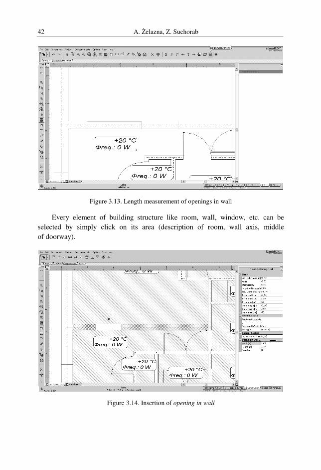
After the change of base visibility, the openings in the wall are easy to notice
and measure. The measurement can be done by Length measurement command
from Functions toolbar (Figure 3.13). Having the dimensions of openings
measured, the user can move back to Construction edit scope.
A. Żelazna, Z. Suchorab 42
Figure 3.13. Length measurement of openings in wall
Every element of building structure like room, wall, window, etc. can be
selected by simply click on its area (description of room, wall axis, middle
of doorway).
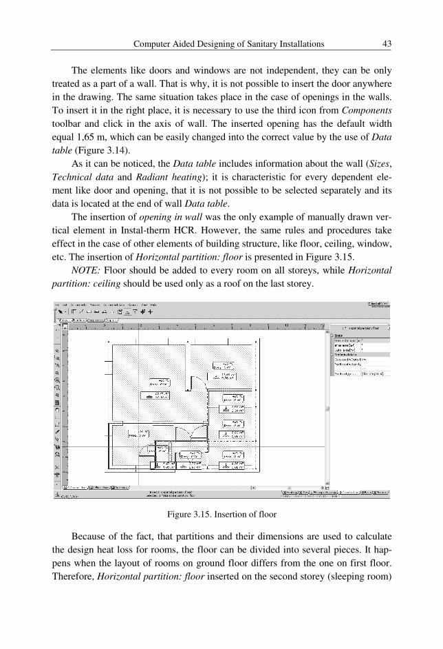
Figure 3.14. Insertion of opening in wall
Computer Aided Designing of Sanitary Installations 43
The elements like doors and windows are not independent, they can be only
treated as a part of a wall. That is why, it is not possible to insert the door anywhere
in the drawing. The same situation takes place in the case of openings in the walls.
To insert it in the right place, it is necessary to use the third icon from Components
toolbar and click in the axis of wall. The inserted opening has the default width
equal 1,65 m, which can be easily changed into the correct value by the use of Data
table (Figure 3.14).
As it can be noticed, the Data table includes information about the wall (Sizes,
Technical data and Radiant heating); it is characteristic for every dependent ele-
ment like door and opening, that it is not possible to be selected separately and its
data is located at the end of wall Data table.
The insertion of opening in wall was the only example of manually drawn ver-
tical element in Instal-therm HCR. However, the same rules and procedures take
effect in the case of other elements of building structure, like floor, ceiling, window,
etc. The insertion of Horizontal partition: floor is presented in Figure 3.15.
NOTE: Floor should be added to every room on all storeys, while Horizontal
partition: ceiling should be used only as a roof on the last storey.
Figure 3.15. Insertion of floor
Because of the fact, that partitions and their dimensions are used to calculate
the design heat loss for rooms, the floor can be divided into several pieces. It hap-
pens when the layout of rooms on ground floor differs from the one on first floor.
Therefore, Horizontal partition: floor inserted on the second storey (sleeping room)
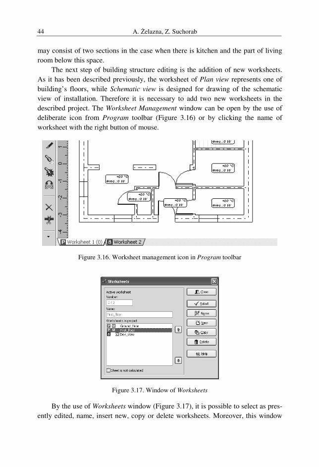
A. Żelazna, Z. Suchorab 44
may consist of two sections in the case when there is kitchen and the part of living
room below this space.
The next step of building structure editing is the addition of new worksheets.
As it has been described previously, the worksheet of Plan view represents one of
building’s floors, while Schematic view is designed for drawing of the schematic
view of installation. Therefore it is necessary to add two new worksheets in the
described project. The Worksheet Management window can be open by the use of
deliberate icon from Program toolbar (Figure 3.16) or by clicking the name of
worksheet with the right button of mouse.
Figure 3.16. Worksheet management icon in Program toolbar
Figure 3.17. Window of Worksheets
By the use of Worksheets window (Figure 3.17), it is possible to select as pres-
ently edited, name, insert new, copy or delete worksheets. Moreover, this window
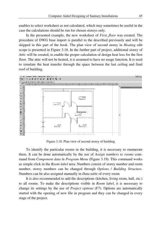
Computer Aided Designing of Sanitary Installations 45
enables to select worksheet as not calculated, which may sometimes be useful in the
case the calculations should be run for chosen storeys only.
In the presented example, the new worksheet of First_floor was created. The
procedure of DWG base import is parallel to the described previously and will be
skipped in this part of the book. The plan view of second storey in Heating edit
scope is presented in Figure 3.18. In the further part of project, additional storey of
Attic will be created, to enable the proper calculation of design heat loss for the first
floor. The attic will not be heated, it is assumed to have no usage function. It is used
to simulate the heat transfer through the space between the last ceiling and final
roof of building.
Figure 3.18. Plan view of second storey of building
To identify the particular rooms in the building, it is necessary to enumerate
them. It can be done automatically by the use of Assign numbers to rooms com-
mand from Component data in Program Menu (Figure 3.19). This command works
as simple click in the Room label area. Numbers consist of storey number and room
number; storey numbers can be changed through Options / Building Structure.
Numbers can be also assigned manually in Data table of every room.
It is also recommended to add the descriptions (kitchen, living room, hall, etc.)
to all rooms. To make the descriptions visible in Room label, it is necessary to
change its settings by the use of Project options (F7). Options are automatically
started with the opening of new file in program and they can be changed in every
stage of the project.
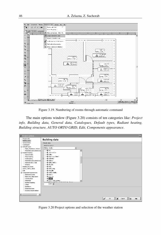
A. Żelazna, Z. Suchorab 46
Figure 3.19. Numbering of rooms through automatic command
The main options window (Figure 3.20) consists of ten categories like: Project
info, Building data, General data, Catalogues, Default types, Radiant heating,
Building structure, AUTO ORTO GRID, Edit, Components appearance.
Figure 3.20 Project options and selection of the weather station
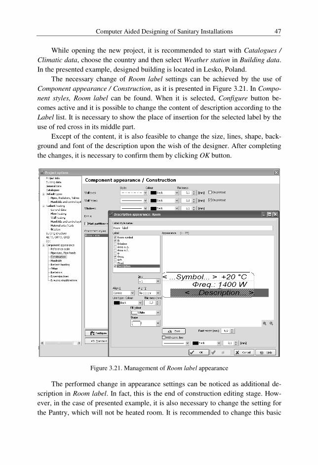
Computer Aided Designing of Sanitary Installations 47
While opening the new project, it is recommended to start with Catalogues /
Climatic data, choose the country and then select Weather station in Building data.
In the presented example, designed building is located in Lesko, Poland.
The necessary change of Room label settings can be achieved by the use of
Component appearance / Construction, as it is presented in Figure 3.21. In Compo-
nent styles, Room label can be found. When it is selected, Configure button be-
comes active and it is possible to change the content of description according to the
Label list. It is necessary to show the place of insertion for the selected label by the
use of red cross in its middle part.
Except of the content, it is also feasible to change the size, lines, shape, back-
ground and font of the description upon the wish of the designer. After completing
the changes, it is necessary to confirm them by clicking OK button.
Figure 3.21. Management of Room label appearance
The performed change in appearance settings can be noticed as additional de-
scription in Room label. In fact, this is the end of construction editing stage. How-
ever, in the case of presented example, it is also necessary to change the setting for
the Pantry, which will not be heated room. It is recommended to change this basic
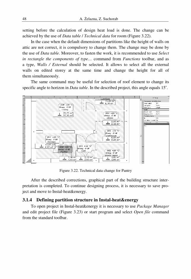
A. Żelazna, Z. Suchorab 48
setting before the calculation of design heat load is done. The change can be
achieved by the use of Data table / Technical data for room (Figure 3.22).
In the case when the default dimensions of partitions like the height of walls on
attic are not correct, it is compulsory to change them. The change may be done by
the use of Data table. Moreover, to fasten the work, it is recommended to use Select
in rectangle the components of type… command from Functions toolbar, and as
a type, Walls / External should be selected. It allows to select all the external
walls on edited storey at the same time and change the height for all of
them simultaneously.
The same command may be useful for selection of roof element to change its
specific angle to horizon in Data table. In the described project, this angle equals 15˚.
Figure 3.22. Technical data change for Pantry
After the described corrections, graphical part of the building structure inter-
pretation is completed. To continue designing process, it is necessary to save pro-
ject and move to Instal-heat&energy.
3.1.4 Defining partition structure in Instal-heat&energy
To open project in Instal-heat&energy it is necessary to use Package Manager
and edit project file (Figure 3.23) or start program and select Open file command
from the standard toolbar.
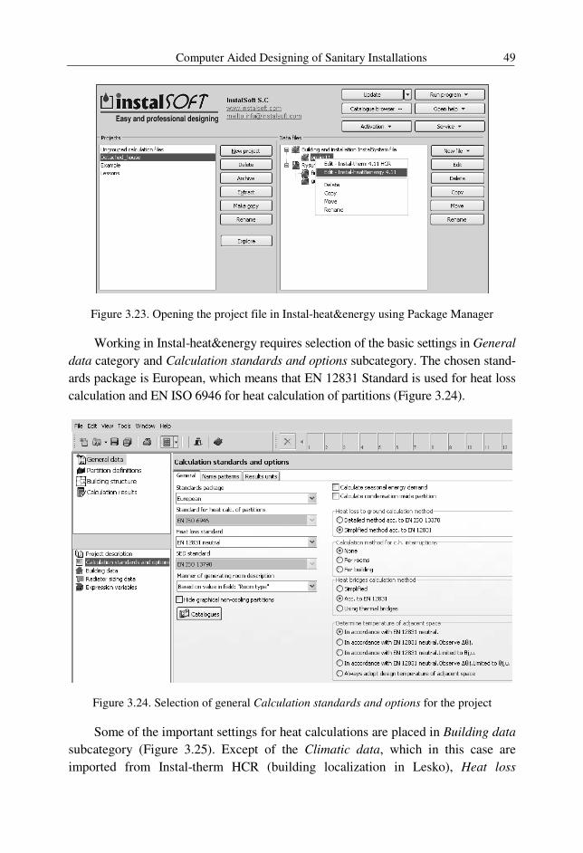
Computer Aided Designing of Sanitary Installations 49
Figure 3.23. Opening the project file in Instal-heat&energy using Package Manager
Working in Instal-heat&energy requires selection of the basic settings in General
data category and Calculation standards and options subcategory. The chosen stand-
ards package is European, which means that EN 12831 Standard is used for heat loss
calculation and EN ISO 6946 for heat calculation of partitions (Figure 3.24).
Figure 3.24. Selection of general Calculation standards and options for the project
Some of the important settings for heat calculations are placed in Building data
subcategory (Figure 3.25). Except of the Climatic data, which in this case are
imported from Instal-therm HCR (building localization in Lesko), Heat loss
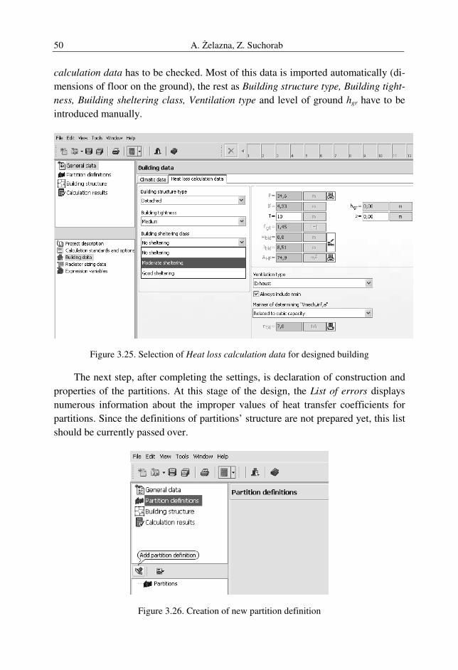
A. Żelazna, Z. Suchorab 50
calculation data has to be checked. Most of this data is imported automatically (di-
mensions of floor on the ground), the rest as Building structure type, Building tight-
ness, Building sheltering class, Ventilation type and level of ground hgr have to be
introduced manually.
Figure 3.25. Selection of Heat loss calculation data for designed building
The next step, after completing the settings, is declaration of construction and
properties of the partitions. At this stage of the design, the List of errors displays
numerous information about the improper values of heat transfer coefficients for
partitions. Since the definitions of partitions’ structure are not prepared yet, this list
should be currently passed over.
Figure 3.26. Creation of new partition definition
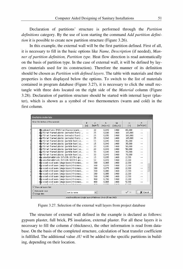
Computer Aided Designing of Sanitary Installations 51
Declaration of partitions’ structure is performed through the Partition
definitions category. By the use of icon starting the command Add partition defini-
tion it is possible to create new partition structure (Figure 3.26).
In this example, the external wall will be the first partition defined. First of all,
it is necessary to fill in the basic options like Name, Description (if needed), Man-
ner of partition definition, Partition type. Heat flow direction is read automatically
on the basis of partition type. In the case of external wall, it will be defined by lay-
ers (materials used for its construction). Therefore the manner of its definition
should be chosen as Partition with defined layers. The table with materials and their
properties is then displayed below the options. To switch to the list of materials
contained in program database (Figure 3.27), it is necessary to click the small rec-
tangle with three dots located on the right side of the Material column (Figure
3.28). Declaration of partition structure should be started with internal layer (plas-
ter), which is shown as a symbol of two thermometers (warm and cold) in the
first column.
Figure 3.27. Selection of the external wall layers from project database
The structure of external wall defined in the example is declared as follows:
gypsum plaster, full brick, PS insulation, external plaster. For all these layers it is
necessary to fill the column d (thickness), the other information is read from data-
base. On the basis of the completed structure, calculation of heat transfer coefficient
is fulfilled. The additional value ∆U will be added to the specific partitions in build-
ing, depending on their location.
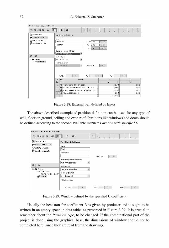
A. Żelazna, Z. Suchorab 52
Figure 3.28. External wall defined by layers
The above described example of partition definition can be used for any type of
wall, floor on ground, ceiling and even roof. Partitions like windows and doors should
be defined according to the second available manner: Partition with specified U.
Figure 3.29. Window defined by the specified U coefficient
Usually the heat transfer coefficient U is given by producer and it ought to be
written in an empty space in data table, as presented in Figure 3.29. It is crucial to
remember about the Partition type, to be changed. If the computational part of the
project is done using the graphical base, the dimensions of window should not be
completed here, since they are read from the drawings.
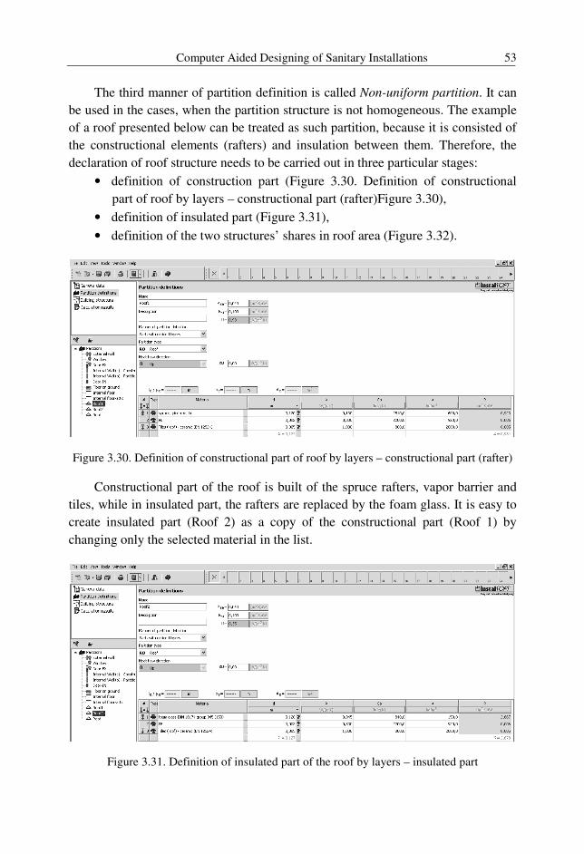
Computer Aided Designing of Sanitary Installations 53
The third manner of partition definition is called Non-uniform partition. It can
be used in the cases, when the partition structure is not homogeneous. The example
of a roof presented below can be treated as such partition, because it is consisted of
the constructional elements (rafters) and insulation between them. Therefore, the
declaration of roof structure needs to be carried out in three particular stages:
• definition of construction part (Figure 3.30. Definition of constructional
part of roof by layers – constructional part (rafter)Figure 3.30),
• definition of insulated part (Figure 3.31),
• definition of the two structures’ shares in roof area (Figure 3.32).
Figure 3.30. Definition of constructional part of roof by layers – constructional part (rafter)
Constructional part of the roof is built of the spruce rafters, vapor barrier and
tiles, while in insulated part, the rafters are replaced by the foam glass. It is easy to
create insulated part (Roof 2) as a copy of the constructional part (Roof 1) by
changing only the selected material in the list.
Figure 3.31. Definition of insulated part of the roof by layers – insulated part
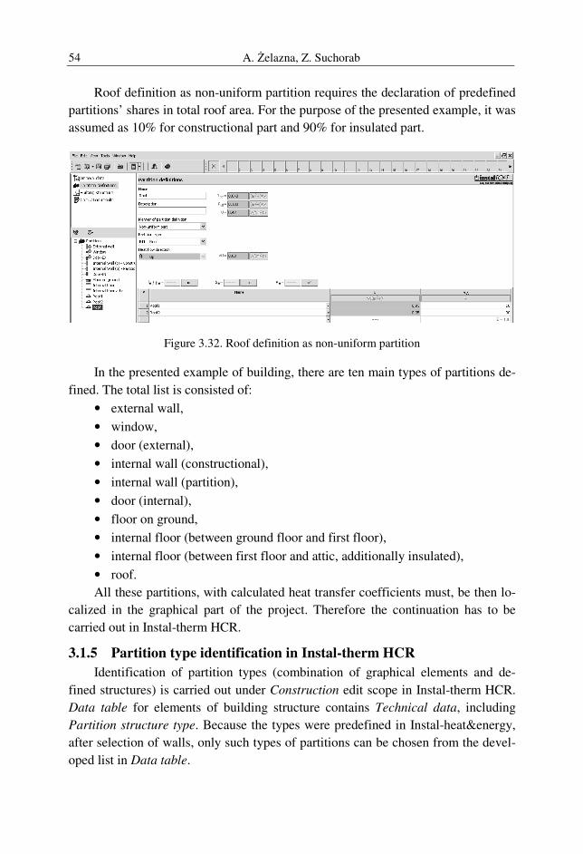
A. Żelazna, Z. Suchorab 54
Roof definition as non-uniform partition requires the declaration of predefined
partitions’ shares in total roof area. For the purpose of the presented example, it was
assumed as 10% for constructional part and 90% for insulated part.
Figure 3.32. Roof definition as non-uniform partition
In the presented example of building, there are ten main types of partitions de-
fined. The total list is consisted of:
• external wall,
• window,
• door (external),
• internal wall (constructional),
• internal wall (partition),
• door (internal),
• floor on ground,
• internal floor (between ground floor and first floor),
• internal floor (between first floor and attic, additionally insulated),
• roof.
All these partitions, with calculated heat transfer coefficients must, be then lo-
calized in the graphical part of the project. Therefore the continuation has to be
carried out in Instal-therm HCR.
3.1.5 Partition type identification in Instal-therm HCR
Identification of partition types (combination of graphical elements and de-
fined structures) is carried out under Construction edit scope in Instal-therm HCR.
Data table for elements of building structure contains Technical data, including
Partition structure type. Because the types were predefined in Instal-heat&energy,
after selection of walls, only such types of partitions can be chosen from the devel-
oped list in Data table.
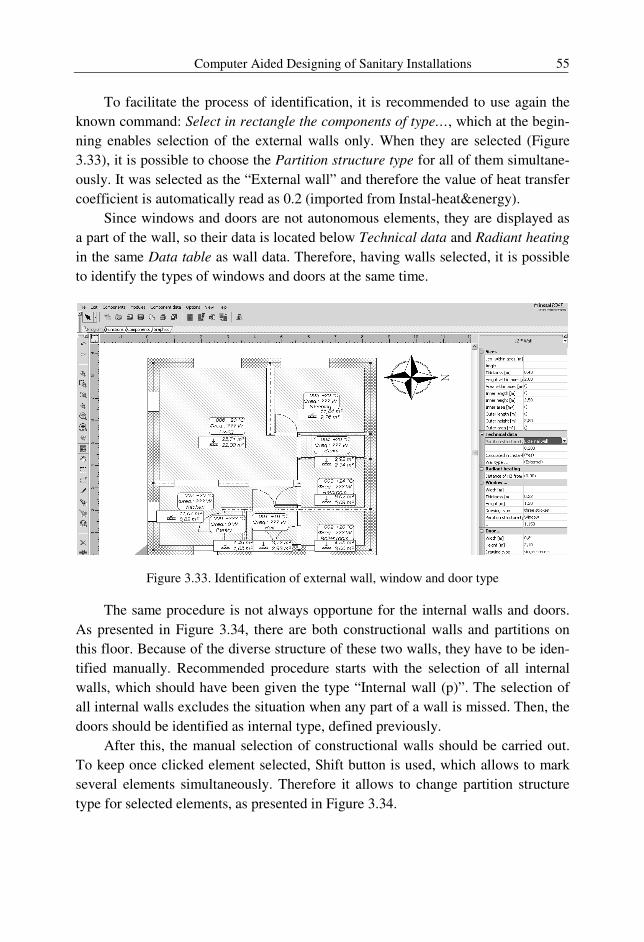
Computer Aided Designing of Sanitary Installations 55
To facilitate the process of identification, it is recommended to use again the
known command: Select in rectangle the components of type…, which at the begin-
ning enables selection of the external walls only. When they are selected (Figure
3.33), it is possible to choose the Partition structure type for all of them simultane-
ously. It was selected as the “External wall” and therefore the value of heat transfer
coefficient is automatically read as 0.2 (imported from Instal-heat&energy).
Since windows and doors are not autonomous elements, they are displayed as
a part of the wall, so their data is located below Technical data and Radiant heating
in the same Data table as wall data. Therefore, having walls selected, it is possible
to identify the types of windows and doors at the same time.
Figure 3.33. Identification of external wall, window and door type
The same procedure is not always opportune for the internal walls and doors.
As presented in Figure 3.34, there are both constructional walls and partitions on
this floor. Because of the diverse structure of these two walls, they have to be iden-
tified manually. Recommended procedure starts with the selection of all internal
walls, which should have been given the type “Internal wall (p)”. The selection of
all internal walls excludes the situation when any part of a wall is missed. Then, the
doors should be identified as internal type, defined previously.
After this, the manual selection of constructional walls should be carried out.
To keep once clicked element selected, Shift button is used, which allows to mark
several elements simultaneously. Therefore it allows to change partition structure
type for selected elements, as presented in Figure 3.34.
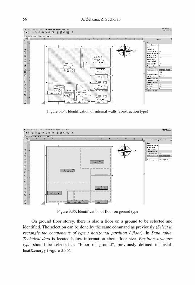
A. Żelazna, Z. Suchorab 56
Figure 3.34. Identification of internal walls (construction type)
Figure 3.35. Identification of floor on ground type
On ground floor storey, there is also a floor on a ground to be selected and
identified. The selection can be done by the same command as previously (Select in
rectangle the components of type / horizontal partition / floor). In Data table,
Technical data is located below information about floor size. Partition structure
type should be selected as “Floor on ground”, previously defined in Instal-
heat&energy (Figure 3.35).
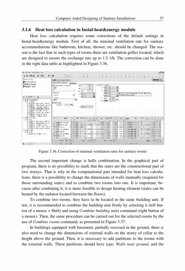
Computer Aided Designing of Sanitary Installations 57
3.1.6 Heat loss calculation in Instal-heat&energy module
Heat loss calculation requires some corrections of the default settings in
Instal-heat&energy module. First of all, the minimal ventilation rate for sanitary
accommodations like bathroom, kitchen, shower, etc. should be changed. The rea-
son is the fact that in such types of rooms there are ventilation grilles located, which
are designed to ensure the exchange rate up to 1.5 1/h. The correction can be done
in the right data table as highlighted in Figure 3.36.
Figure 3.36. Correction of minimal ventilation rates for sanitary rooms
The second important change is halls combination. In the graphical part of
program, there is no possibility to mark that the stairs are the constructional part of
two storeys. That is why in the computational part intended for heat loss calcula-
tions, there is a possibility to change the dimensions of walls manually (required for
those surrounding stairs) and to combine two rooms into one. It is important, be-
cause after combining it, it is more feasible to design heating element (stairs can be
heated by the radiator located between the floors).
To combine two rooms, they have to be located in the same building unit. If
not, it is recommended to combine the building unit firstly by selecting it (left but-
ton of a mouse + Shift) and using Combine building units command (right button of
a mouse). Then, the same procedure can be carried out for the selected rooms by the
use of Combine rooms command, as presented in Figure 3.37.
In buildings equipped with basement, partially recessed in the ground, there is
also need to change the dimensions of external walls on the storey of cellar to the
height above the ground. Then, it is necessary to add partitions to the rooms with
the external walls. These partitions should have type: Walls near ground, and the
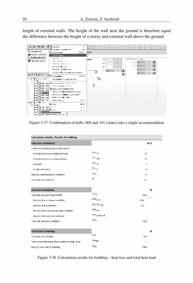
A. Żelazna, Z. Suchorab 58
length of external walls. The height of the wall near the ground is therefore equal
the difference between the height of a storey and external wall above the ground.
Figure 3.37. Combination of halls: 004 and 101 (stairs) into a single accommodation
Figure 3.38. Calculation results for building – heat loss and total heat load
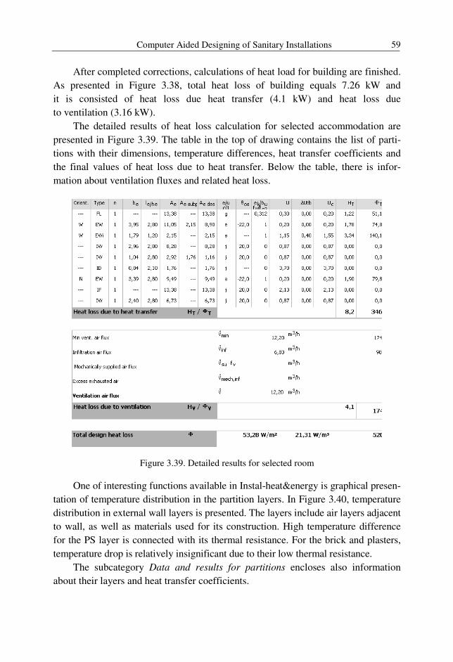
Computer Aided Designing of Sanitary Installations 59
After completed corrections, calculations of heat load for building are finished.
As presented in Figure 3.38, total heat loss of building equals 7.26 kW and
it is consisted of heat loss due heat transfer (4.1 kW) and heat loss due
to ventilation (3.16 kW).
The detailed results of heat loss calculation for selected accommodation are
presented in Figure 3.39. The table in the top of drawing contains the list of parti-
tions with their dimensions, temperature differences, heat transfer coefficients and
the final values of heat loss due to heat transfer. Below the table, there is infor-
mation about ventilation fluxes and related heat loss.
Figure 3.39. Detailed results for selected room
One of interesting functions available in Instal-heat&energy is graphical presen-
tation of temperature distribution in the partition layers. In Figure 3.40, temperature
distribution in external wall layers is presented. The layers include air layers adjacent
to wall, as well as materials used for its construction. High temperature difference
for the PS layer is connected with its thermal resistance. For the brick and plasters,
temperature drop is relatively insignificant due to their low thermal resistance.
The subcategory Data and results for partitions encloses also information
about their layers and heat transfer coefficients.
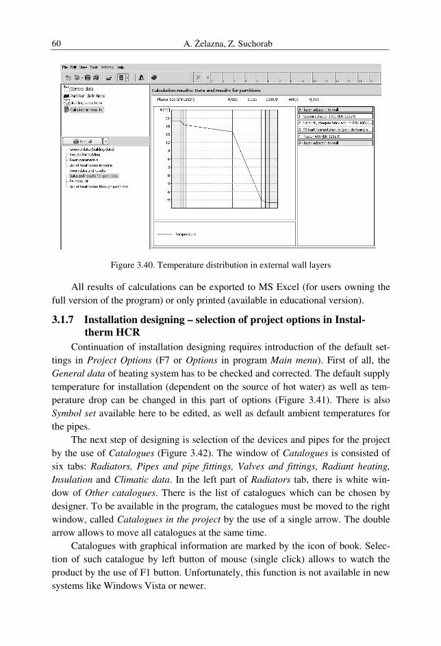
A. Żelazna, Z. Suchorab 60
Figure 3.40. Temperature distribution in external wall layers
All results of calculations can be exported to MS Excel (for users owning the
full version of the program) or only printed (available in educational version).
3.1.7 Installation designing – selection of project options in Instal-
therm HCR
Continuation of installation designing requires introduction of the default set-
tings in Project Options (F7 or Options in program Main menu). First of all, the
General data of heating system has to be checked and corrected. The default supply
temperature for installation (dependent on the source of hot water) as well as tem-
perature drop can be changed in this part of options (Figure 3.41). There is also
Symbol set available here to be edited, as well as default ambient temperatures for
the pipes.
The next step of designing is selection of the devices and pipes for the project
by the use of Catalogues (Figure 3.42). The window of Catalogues is consisted of
six tabs: Radiators, Pipes and pipe fittings, Valves and fittings, Radiant heating,
Insulation and Climatic data. In the left part of Radiators tab, there is white win-
dow of Other catalogues. There is the list of catalogues which can be chosen by
designer. To be available in the program, the catalogues must be moved to the right
window, called Catalogues in the project by the use of a single arrow. The double
arrow allows to move all catalogues at the same time.
Catalogues with graphical information are marked by the icon of book. Selec-
tion of such catalogue by left button of mouse (single click) allows to watch the
product by the use of F1 button. Unfortunately, this function is not available in new
systems like Windows Vista or newer.
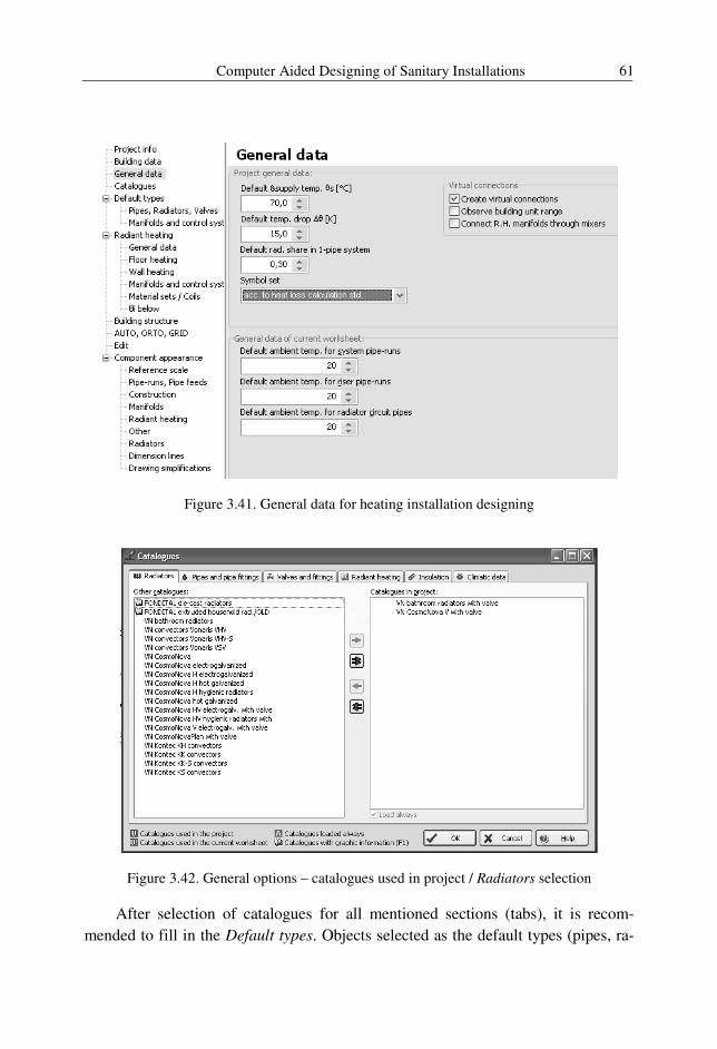
Computer Aided Designing of Sanitary Installations 61
Figure 3.41. General data for heating installation designing
Figure 3.42. General options – catalogues used in project / Radiators selection
After selection of catalogues for all mentioned sections (tabs), it is recom-
mended to fill in the Default types. Objects selected as the default types (pipes, ra-
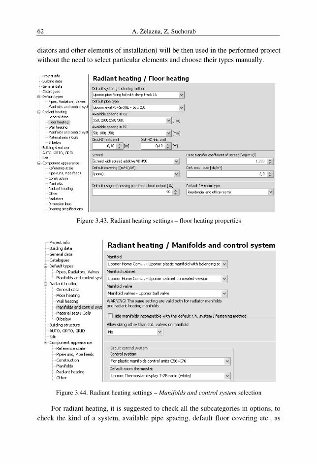
A. Żelazna, Z. Suchorab 62
diators and other elements of installation) will be then used in the performed project
without the need to select particular elements and choose their types manually.
Figure 3.43. Radiant heating settings – floor heating properties
Figure 3.44. Radiant heating settings – Manifolds and control system selection
For radiant heating, it is suggested to check all the subcategories in options, to
check the kind of a system, available pipe spacing, default floor covering etc., as
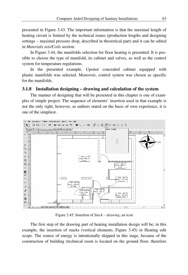
Computer Aided Designing of Sanitary Installations 63
presented in Figure 3.43. The important information is that the maximal length of
heating circuit is limited by the technical issues (production lengths and designing
settings – maximal pressure drop, described in theoretical part) and it can be edited
in Materials sets/Coils section.
In Figure 3.44, the manifolds selection for floor heating is presented. It is pos-
sible to choose the type of manifold, its cabinet and valves, as well as the control
system for temperature regulations.
In the presented example, Uponor concealed cabinet equipped with
plastic manifolds was selected. Moreover, control system was chosen as specific
for the manifolds.
3.1.8 Installation designing – drawing and calculation of the system
The manner of designing that will be presented in this chapter is one of exam-
ples of simple project. The sequence of elements’ insertion used in that example is
not the only right, however, as authors stated on the basis of own experience, it is
one of the simpliest.
Figure 3.45. Insertion of Stack – drawing; an icon
The first step of the drawing part of heating installation design will be, in this
example, the insertion of stacks (vertical elements, Figure 3.45) in Heating edit
scope. The source of energy is intentionally skipped in this stage, because of the
construction of building (technical room is located on the ground floor, therefore
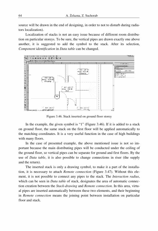
A. Żelazna, Z. Suchorab 64
source will be drawn in the end of designing, in order to not to disturb during radia-
tors localization).
Localization of stacks is not an easy issue because of different room distribu-
tion on particular storeys. To be sure, the vertical pipes are drawn exactly one above
another, it is suggested to add the symbol to the stack. After its selection,
Component identification in Data table can be changed.
Figure 3.46. Stack inserted on ground floor storey
In the example, the given symbol is “1” (Figure 3.46). If it is added to a stack
on ground floor, the same stack on the first floor will be applied automatically to
the matching coordinates. It is a very useful function in the case of high buildings
with many floors.
In the case of presented example, the above mentioned issue is not so im-
portant because the main distributing pipes will be conducted under the ceiling of
the ground floor, so vertical pipes can be separate for ground and first floors. By the
use of Data table, it is also possible to change connections in riser (the supply
and the return).
The inserted stack is only a drawing symbol, to make it a part of the installa-
tion, it is necessary to attach Remote connection (Figure 3.47). Without this ele-
ment, it is not possible to connect any pipes to the stack. The Interaction radius,
which can be seen in Data table of stack, designates the area of automatic connec-
tion creation between the Stack-drawing and Remote connection. In this area, virtu-
al pipes are inserted automatically between these two elements, and their beginning
in Remote connection means the joining point between installation on particular
floor and stack.
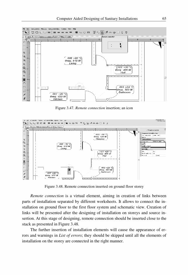
Computer Aided Designing of Sanitary Installations 65
Figure 3.47. Remote connection insertion; an icon
Figure 3.48. Remote connection inserted on ground floor storey
Remote connection is a virtual element, aiming in creation of links between
parts of installation separated by different worksheets. It allows to connect the in-
stallation on ground floor to the first floor system and schematic view. Creation of
links will be presented after the designing of installation on storeys and source in-
sertion. At this stage of designing, remote connection should be inserted close to the
stack as presented in Figure 3.48.
The further insertion of installation elements will cause the appearance of er-
rors and warnings in List of errors; they should be skipped until all the elements of
installation on the storey are connected in the right manner.
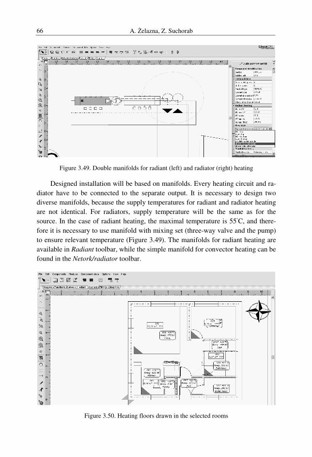
A. Żelazna, Z. Suchorab 66
Figure 3.49. Double manifolds for radiant (left) and radiator (right) heating
Designed installation will be based on manifolds. Every heating circuit and ra-
diator have to be connected to the separate output. It is necessary to design two
diverse manifolds, because the supply temperatures for radiant and radiator heating
are not identical. For radiators, supply temperature will be the same as for the
source. In the case of radiant heating, the maximal temperature is 55◦C, and there-
fore it is necessary to use manifold with mixing set (three-way valve and the pump)
to ensure relevant temperature (Figure 3.49). The manifolds for radiant heating are
available in Radiant toolbar, while the simple manifold for convector heating can be
found in the Netork/radiator toolbar.
Figure 3.50. Heating floors drawn in the selected rooms
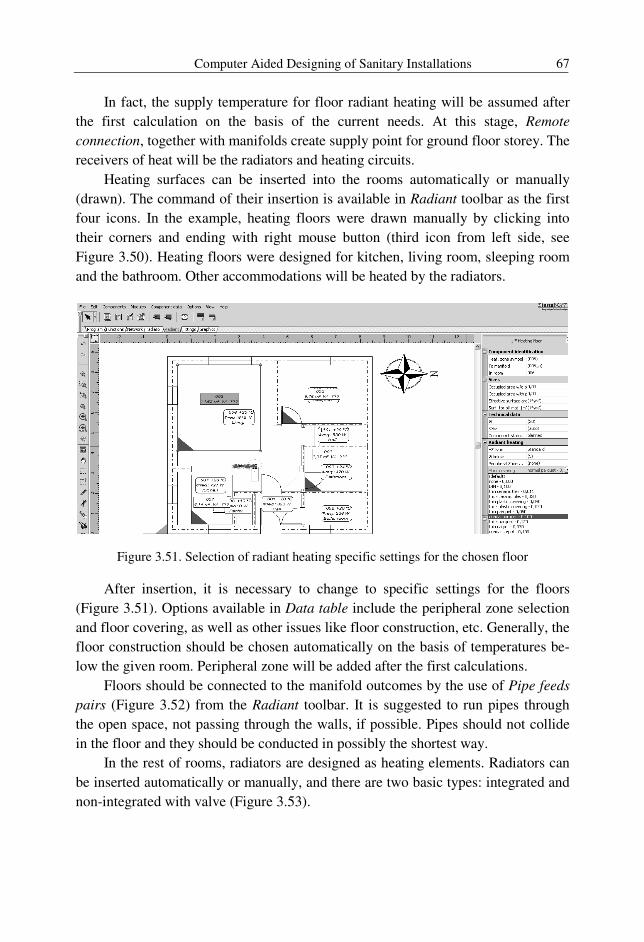
Computer Aided Designing of Sanitary Installations 67
In fact, the supply temperature for floor radiant heating will be assumed after
the first calculation on the basis of the current needs. At this stage, Remote
connection, together with manifolds create supply point for ground floor storey. The
receivers of heat will be the radiators and heating circuits.
Heating surfaces can be inserted into the rooms automatically or manually
(drawn). The command of their insertion is available in Radiant toolbar as the first
four icons. In the example, heating floors were drawn manually by clicking into
their corners and ending with right mouse button (third icon from left side, see
Figure 3.50). Heating floors were designed for kitchen, living room, sleeping room
and the bathroom. Other accommodations will be heated by the radiators.
Figure 3.51. Selection of radiant heating specific settings for the chosen floor
After insertion, it is necessary to change to specific settings for the floors
(Figure 3.51). Options available in Data table include the peripheral zone selection
and floor covering, as well as other issues like floor construction, etc. Generally, the
floor construction should be chosen automatically on the basis of temperatures be-
low the given room. Peripheral zone will be added after the first calculations.
Floors should be connected to the manifold outcomes by the use of Pipe feeds
pairs (Figure 3.52) from the Radiant toolbar. It is suggested to run pipes through
the open space, not passing through the walls, if possible. Pipes should not collide
in the floor and they should be conducted in possibly the shortest way.
In the rest of rooms, radiators are designed as heating elements. Radiators can
be inserted automatically or manually, and there are two basic types: integrated and
non-integrated with valve (Figure 3.53).
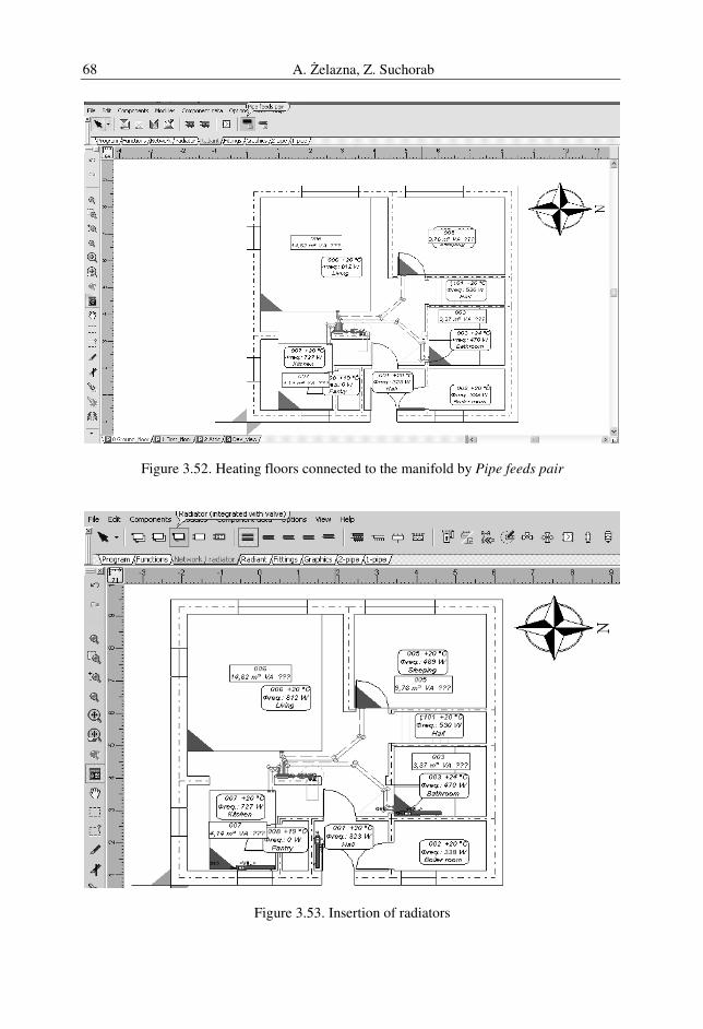
A. Żelazna, Z. Suchorab 68
Figure 3.52. Heating floors connected to the manifold by Pipe feeds pair
Figure 3.53. Insertion of radiators
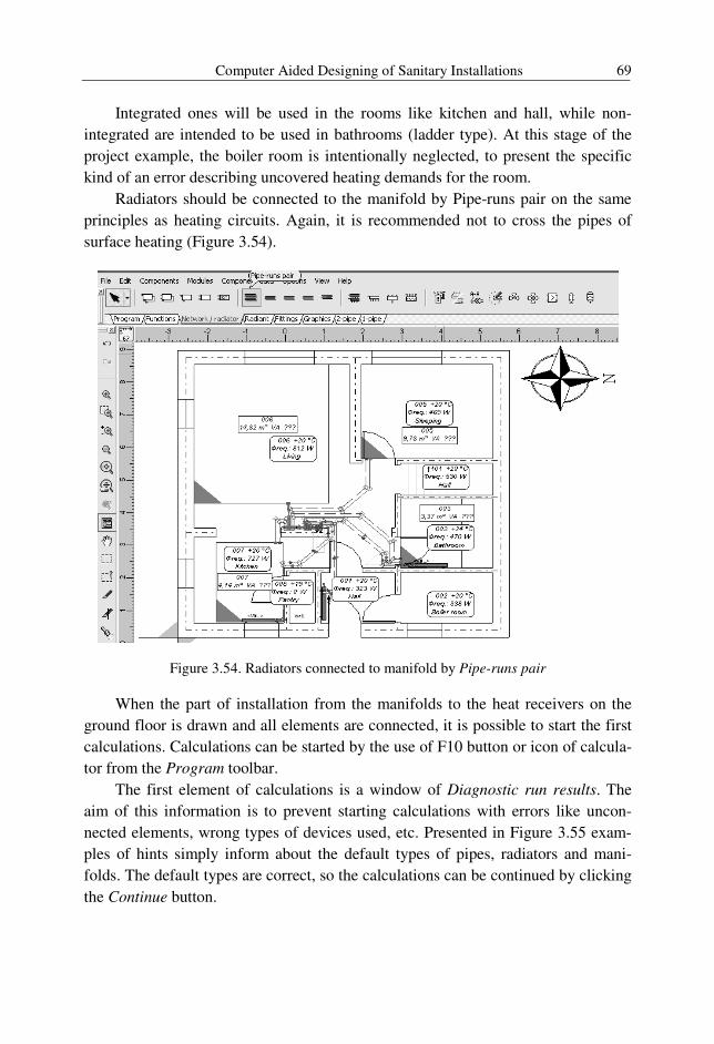
Computer Aided Designing of Sanitary Installations 69
Integrated ones will be used in the rooms like kitchen and hall, while non-
integrated are intended to be used in bathrooms (ladder type). At this stage of the
project example, the boiler room is intentionally neglected, to present the specific
kind of an error describing uncovered heating demands for the room.
Radiators should be connected to the manifold by Pipe-runs pair on the same
principles as heating circuits. Again, it is recommended not to cross the pipes of
surface heating (Figure 3.54).
Figure 3.54. Radiators connected to manifold by Pipe-runs pair
When the part of installation from the manifolds to the heat receivers on the
ground floor is drawn and all elements are connected, it is possible to start the first
calculations. Calculations can be started by the use of F10 button or icon of calcula-
tor from the Program toolbar.
The first element of calculations is a window of Diagnostic run results. The
aim of this information is to prevent starting calculations with errors like uncon-
nected elements, wrong types of devices used, etc. Presented in Figure 3.55 exam-
ples of hints simply inform about the default types of pipes, radiators and mani-
folds. The default types are correct, so the calculations can be continued by clicking
the Continue button.
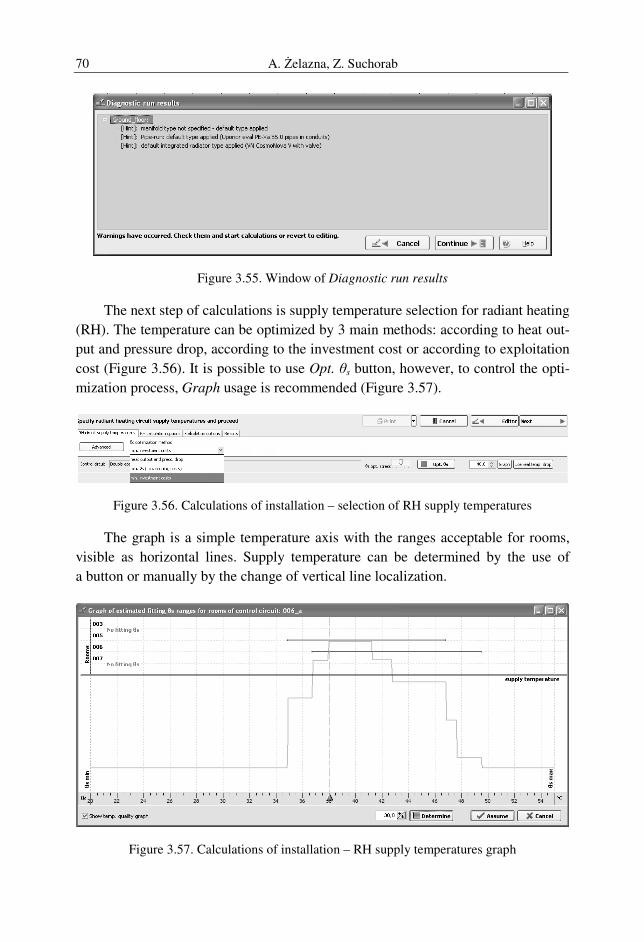
A. Żelazna, Z. Suchorab 70
Figure 3.55. Window of Diagnostic run results
The next step of calculations is supply temperature selection for radiant heating
(RH). The temperature can be optimized by 3 main methods: according to heat out-
put and pressure drop, according to the investment cost or according to exploitation
cost (Figure 3.56). It is possible to use Opt. θs button, however, to control the opti-
mization process, Graph usage is recommended (Figure 3.57).
Figure 3.56. Calculations of installation – selection of RH supply temperatures
The graph is a simple temperature axis with the ranges acceptable for rooms,
visible as horizontal lines. Supply temperature can be determined by the use of
a button or manually by the change of vertical line localization.
Figure 3.57. Calculations of installation – RH supply temperatures graph
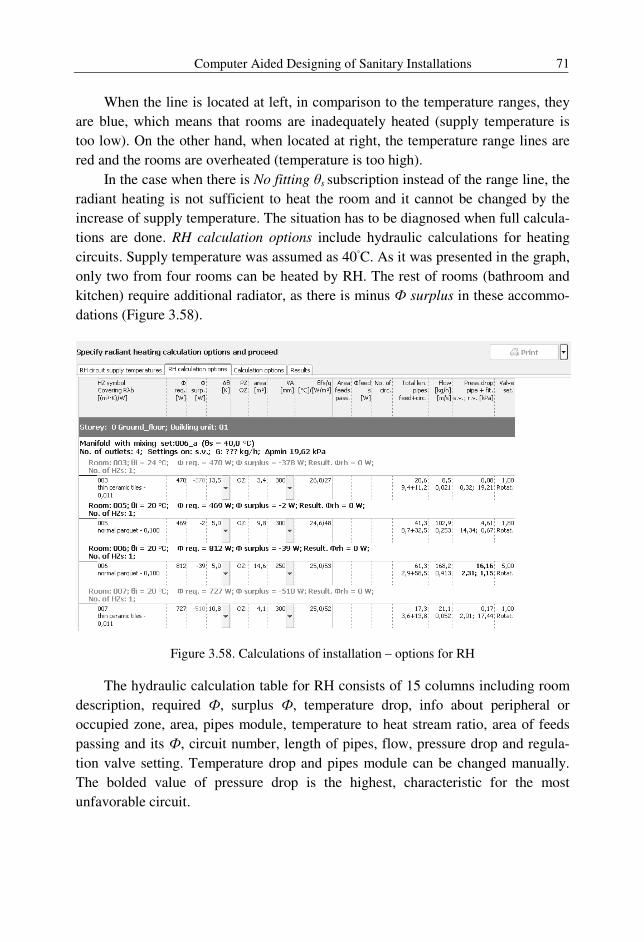
Computer Aided Designing of Sanitary Installations 71
When the line is located at left, in comparison to the temperature ranges, they
are blue, which means that rooms are inadequately heated (supply temperature is
too low). On the other hand, when located at right, the temperature range lines are
red and the rooms are overheated (temperature is too high).
In the case when there is No fitting θs subscription instead of the range line, the
radiant heating is not sufficient to heat the room and it cannot be changed by the
increase of supply temperature. The situation has to be diagnosed when full calcula-
tions are done. RH calculation options include hydraulic calculations for heating
circuits. Supply temperature was assumed as 40◦C. As it was presented in the graph,
only two from four rooms can be heated by RH. The rest of rooms (bathroom and
kitchen) require additional radiator, as there is minus Ф surplus in these accommo-
dations (Figure 3.58).
Figure 3.58. Calculations of installation – options for RH
The hydraulic calculation table for RH consists of 15 columns including room
description, required Ф, surplus Ф, temperature drop, info about peripheral or
occupied zone, area, pipes module, temperature to heat stream ratio, area of feeds
passing and its Ф, circuit number, length of pipes, flow, pressure drop and regula-
tion valve setting. Temperature drop and pipes module can be changed manually.
The bolded value of pressure drop is the highest, characteristic for the most
unfavorable circuit.
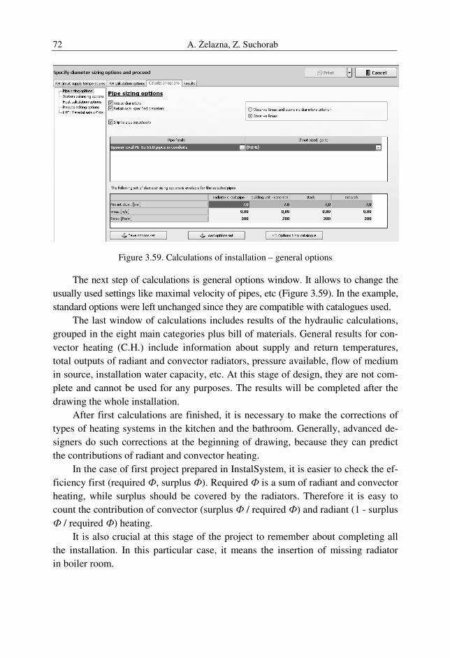
A. Żelazna, Z. Suchorab 72
Figure 3.59. Calculations of installation – general options
The next step of calculations is general options window. It allows to change the
usually used settings like maximal velocity of pipes, etc (Figure 3.59). In the example,
standard options were left unchanged since they are compatible with catalogues used.
The last window of calculations includes results of the hydraulic calculations,
grouped in the eight main categories plus bill of materials. General results for con-
vector heating (C.H.) include information about supply and return temperatures,
total outputs of radiant and convector radiators, pressure available, flow of medium
in source, installation water capacity, etc. At this stage of design, they are not com-
plete and cannot be used for any purposes. The results will be completed after the
drawing the whole installation.
After first calculations are finished, it is necessary to make the corrections of
types of heating systems in the kitchen and the bathroom. Generally, advanced de-
signers do such corrections at the beginning of drawing, because they can predict
the contributions of radiant and convector heating.
In the case of first project prepared in InstalSystem, it is easier to check the ef-
ficiency first (required Ф, surplus Ф). Required Ф is a sum of radiant and convector
heating, while surplus should be covered by the radiators. Therefore it is easy to
count the contribution of convector (surplus Ф / required Ф) and radiant (1 - surplus
Ф / required Ф) heating.
It is also crucial at this stage of the project to remember about completing all
the installation. In this particular case, it means the insertion of missing radiator
in boiler room.
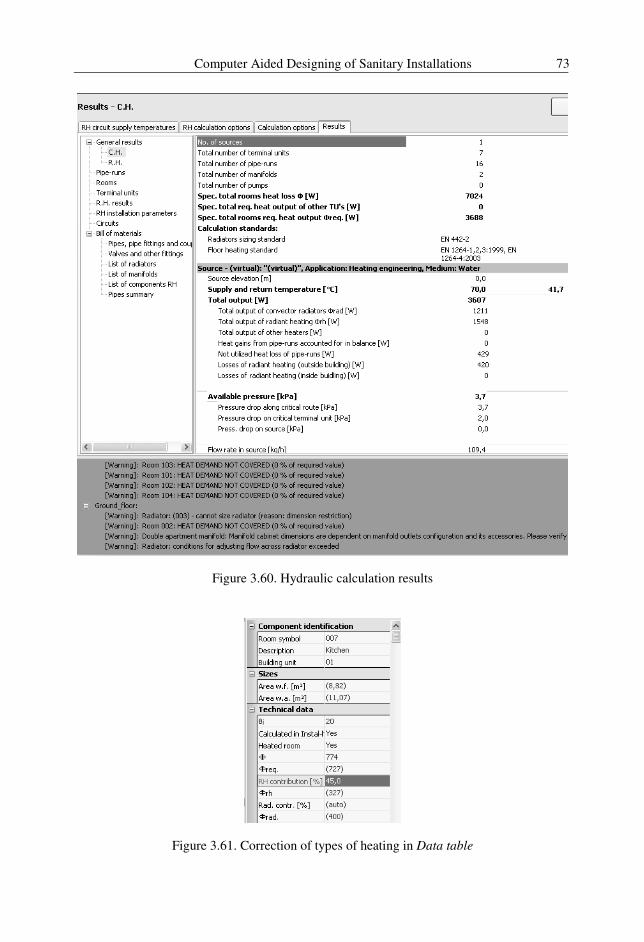
Computer Aided Designing of Sanitary Installations 73
Figure 3.60. Hydraulic calculation results
Figure 3.61. Correction of types of heating in Data table
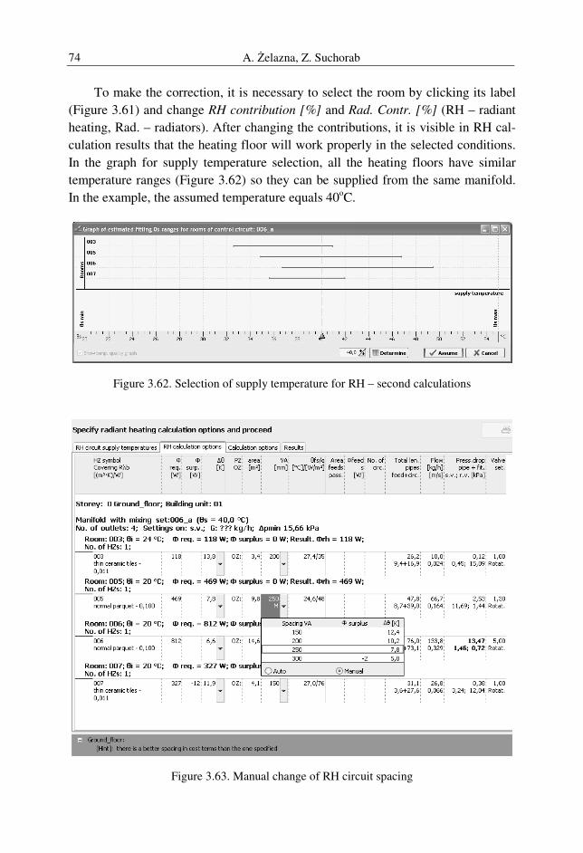
A. Żelazna, Z. Suchorab 74
To make the correction, it is necessary to select the room by clicking its label
(Figure 3.61) and change RH contribution [%] and Rad. Contr. [%] (RH – radiant
heating, Rad. – radiators). After changing the contributions, it is visible in RH cal-
culation results that the heating floor will work properly in the selected conditions.
In the graph for supply temperature selection, all the heating floors have similar
temperature ranges (Figure 3.62) so they can be supplied from the same manifold.
In the example, the assumed temperature equals 40oC.
Figure 3.62. Selection of supply temperature for RH – second calculations
Figure 3.63. Manual change of RH circuit spacing

Computer Aided Designing of Sanitary Installations 75
In some cases, it may be necessary to use manual selection of RH properties
like temperature drop and pipes spacing. It may happen when there is a small, mi-
nus Ф Surplus and the selected way of system optimization does not allow to find
the right solution. In such case, the manual selection of temperature drop and spac-
ing is recommended (Figure 3.63).
Figure 3.64. Results of calculations with Warnings and Hints
When calculations are finished, it is necessary to correct all the warnings for
the ground floor storey. The list of warnings is available in the List of errors
window and elements with warnings can be easily localized by simple clicking the
particular one on the list. The first one – cannot size radiator – is active for bath-
room radiator, which become selected after clicking in warning. The dimensions of
bathroom radiators are not standard – they are usually higher, therefore it is neces-
sary to change Size limits in Data table (Figure 3.65).
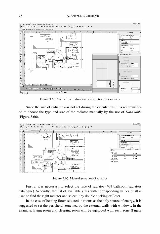
A. Żelazna, Z. Suchorab 76
Figure 3.65. Correction of dimension restrictions for radiator
Since the size of radiator was not set during the calculations, it is recommend-
ed to choose the type and size of the radiator manually by the use of Data table
(Figure 3.66).
Figure 3.66. Manual selection of radiator
Firstly, it is necessary to select the type of radiator (VN bathroom radiators
catalogue). Secondly, the list of available sizes with corresponding values of Ф is
used to find the right radiator and select it by double clicking or Enter.
In the case of heating floors situated in rooms as the only source of energy, it is
suggested to set the peripheral zone nearby the external walls with windows. In the
example, living room and sleeping room will be equipped with such zone (Figure
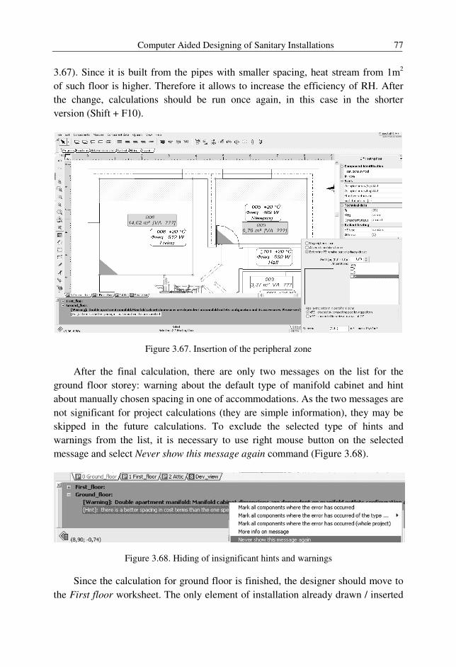
Computer Aided Designing of Sanitary Installations 77
3.67). Since it is built from the pipes with smaller spacing, heat stream from 1m2
of such floor is higher. Therefore it allows to increase the efficiency of RH. After
the change, calculations should be run once again, in this case in the shorter
version (Shift + F10).
Figure 3.67. Insertion of the peripheral zone
After the final calculation, there are only two messages on the list for the
ground floor storey: warning about the default type of manifold cabinet and hint
about manually chosen spacing in one of accommodations. As the two messages are
not significant for project calculations (they are simple information), they may be
skipped in the future calculations. To exclude the selected type of hints and
warnings from the list, it is necessary to use right mouse button on the selected
message and select Never show this message again command (Figure 3.68).
Figure 3.68. Hiding of insignificant hints and warnings
Since the calculation for ground floor is finished, the designer should move to
the First floor worksheet. The only element of installation already drawn / inserted
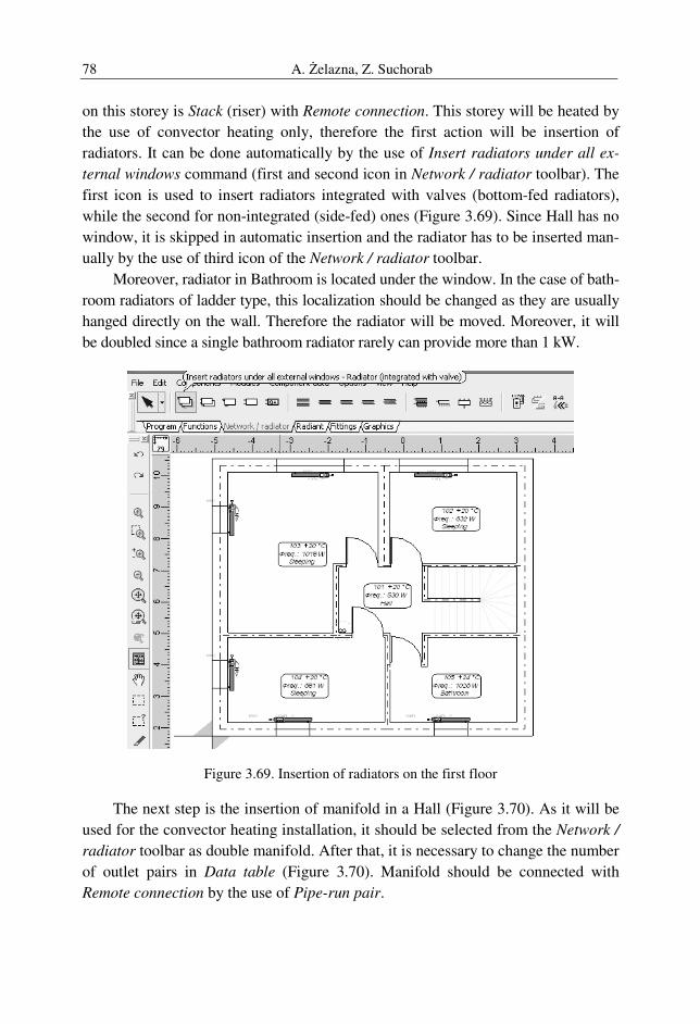
A. Żelazna, Z. Suchorab 78
on this storey is Stack (riser) with Remote connection. This storey will be heated by
the use of convector heating only, therefore the first action will be insertion of
radiators. It can be done automatically by the use of Insert radiators under all ex-
ternal windows command (first and second icon in Network / radiator toolbar). The
first icon is used to insert radiators integrated with valves (bottom-fed radiators),
while the second for non-integrated (side-fed) ones (Figure 3.69). Since Hall has no
window, it is skipped in automatic insertion and the radiator has to be inserted man-
ually by the use of third icon of the Network / radiator toolbar.
Moreover, radiator in Bathroom is located under the window. In the case of bath-
room radiators of ladder type, this localization should be changed as they are usually
hanged directly on the wall. Therefore the radiator will be moved. Moreover, it will
be doubled since a single bathroom radiator rarely can provide more than 1 kW.
Figure 3.69. Insertion of radiators on the first floor
The next step is the insertion of manifold in a Hall (Figure 3.70). As it will be
used for the convector heating installation, it should be selected from the Network /
radiator toolbar as double manifold. After that, it is necessary to change the number
of outlet pairs in Data table (Figure 3.70). Manifold should be connected with
Remote connection by the use of Pipe-run pair.

Computer Aided Designing of Sanitary Installations 79
The same tool is used for connection of the radiators with manifold. Single
Pipe-run pair can be started in manifold outlet and run to the radiator on the basis
of the same rules as in radiant heating, using possibly the shortest way through the
openings in walls and trying not to criss-cross the pipes. In the end, it can be con-
nected to the radiator (manual connection) or left near to it (right mouse button will
finish the command).
Figure 3.70. Insertion of manifold on first floor
In the case, when pipes were left close to the radiators, as presented in Figure
3.71, it is possible to use automatic connection command from Components menu
(Shift + Ctrl + A). It allows to create connection between nearby elements
of the installation.
After connection of all radiators, the installation on the first floor is completed.
In the case of presented example, it consists of eight radiators, manifold, stock,
remote connection and the pipes. Since the radiators are integrated with valves,
there is no need to insert additional fittings. Thermostatic and return valves should
be used only in the case of non-integrated radiators on supply and return
pipe respectively.
To check the correctness of connections, it is necessary to save the file. If the
installation is drawn properly, arrows with flow direction will appear on pipes
(Figure 3.72).
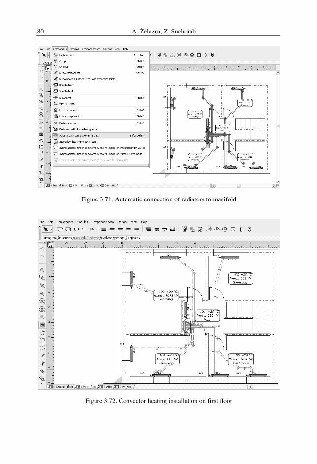
A. Żelazna, Z. Suchorab 80
Figure 3.71. Automatic connection of radiators to manifold
Figure 3.72. Convector heating installation on first floor
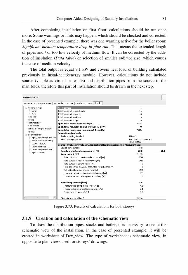
Computer Aided Designing of Sanitary Installations 81
After completing installation on first floor, calculations should be run once
more. Some warnings or hints may happen, which should be checked and corrected.
In the case of presented example, there was one warning active for the boiler room:
Significant medium temperature drop in pipe-run. This means the extended length
of pipes and / or too low velocity of medium flow. It can be corrected by the addi-
tion of insulation (Data table) or selection of smaller radiator size, which causes
increase of medium velocity.
The total output is equal 9.1 kW and covers heat load of building calculated
previously in Instal-heat&energy module. However, calculations do not include
source (visible as virtual in results) and distribution pipes from the source to the
manifolds, therefore this part of installation should be drawn in the next step.
Figure 3.73. Results of calculations for both storeys
3.1.9 Creation and calculation of the schematic view
To draw the distribution pipes, stacks and boiler, it is necessary to create the
schematic view of the installation. In the case of presented example, it will be
created in worksheet of Dev_view. The type of worksheet is schematic view, in
opposite to plan views used for storeys’ drawings.
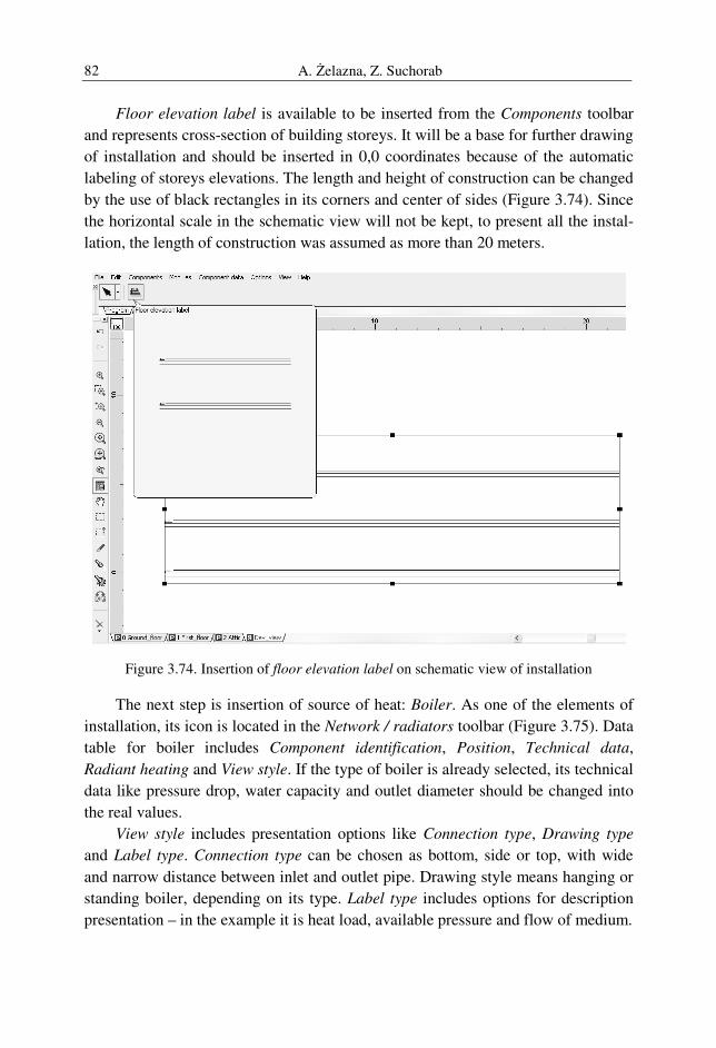
A. Żelazna, Z. Suchorab 82
Floor elevation label is available to be inserted from the Components toolbar
and represents cross-section of building storeys. It will be a base for further drawing
of installation and should be inserted in 0,0 coordinates because of the automatic
labeling of storeys elevations. The length and height of construction can be changed
by the use of black rectangles in its corners and center of sides (Figure 3.74). Since
the horizontal scale in the schematic view will not be kept, to present all the instal-
lation, the length of construction was assumed as more than 20 meters.
Figure 3.74. Insertion of floor elevation label on schematic view of installation
The next step is insertion of source of heat: Boiler. As one of the elements of
installation, its icon is located in the Network / radiators toolbar (Figure 3.75). Data
table for boiler includes Component identification, Position, Technical data,
Radiant heating and View style. If the type of boiler is already selected, its technical
data like pressure drop, water capacity and outlet diameter should be changed into
the real values.
View style includes presentation options like Connection type, Drawing type
and Label type. Connection type can be chosen as bottom, side or top, with wide
and narrow distance between inlet and outlet pipe. Drawing style means hanging or
standing boiler, depending on its type. Label type includes options for description
presentation – in the example it is heat load, available pressure and flow of medium.
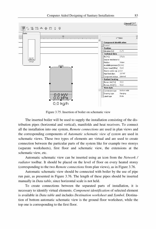
Computer Aided Designing of Sanitary Installations 83
Figure 3.75. Insertion of boiler on schematic view
The inserted boiler will be used to supply the installation consisting of the dis-
tribution pipes (horizontal and vertical), manifolds and heat receivers. To connect
all the installation into one system, Remote connections are used in plan views and
the corresponding components of Automatic schematic view of system are used in
schematic views. These two types of elements are virtual and are used to create
connection between the particular parts of the system like for example two storeys
(separate worksheets), first floor and schematic view, the extensions at the
schematic view, etc.
Automatic schematic view can be inserted using an icon from the Network /
radiator toolbar. It should be placed on the level of floor on every heated storey
(corresponding to the two Remote connections from plan views), as in Figure 3.76.
Automatic schematic view should be connected with boiler by the use of pipe
run pair, as presented in Figure 3.76. The length of these pipes should be inserted
manually in Data table, since horizontal scale is not held.
To create connections between the separated parts of installation, it is
necessary to identify virtual elements. Component identification of selected element
is available in Data table and includes Destination worksheet and Symbol. Destina-
tion of bottom automatic schematic view is the ground floor worksheet, while the
top one is corresponding to the first floor.
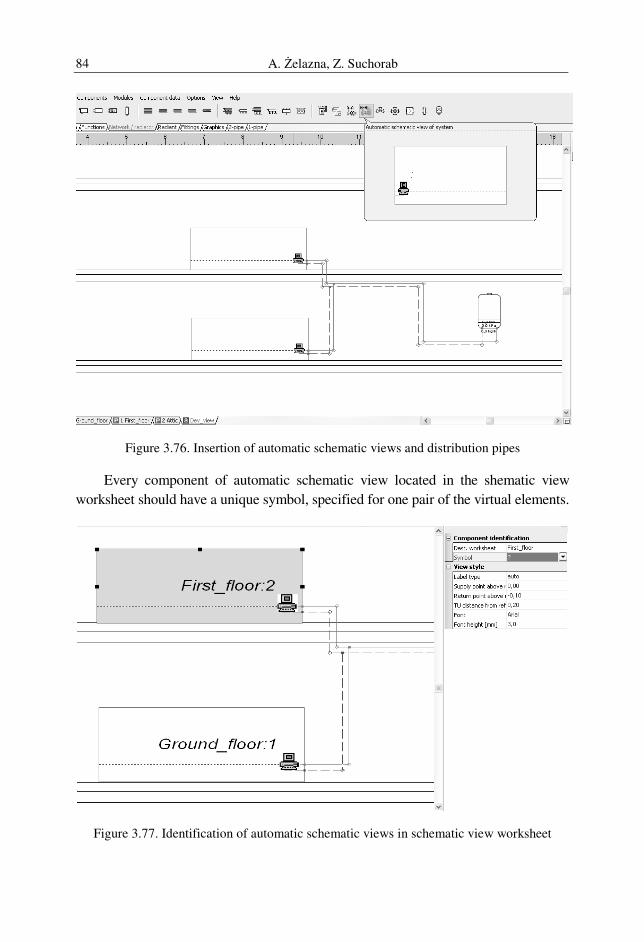
A. Żelazna, Z. Suchorab 84
Figure 3.76. Insertion of automatic schematic views and distribution pipes
Every component of automatic schematic view located in the shematic view
worksheet should have a unique symbol, specified for one pair of the virtual elements.
Figure 3.77. Identification of automatic schematic views in schematic view worksheet
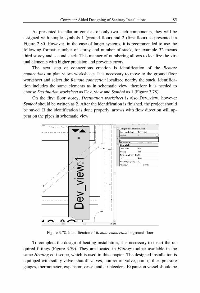
Computer Aided Designing of Sanitary Installations 85
As presented installation consists of only two such components, they will be
assigned with simple symbols 1 (ground floor) and 2 (first floor) as presented in
Figure 2.80. However, in the case of larger systems, it is recommended to use the
following format: number of storey and number of stack, for example 32 means
third storey and second stack. This manner of numbering allows to localize the vir-
tual elements with higher precision and prevents errors.
The next step of connections creation is identification of the Remote
connections on plan views worksheets. It is necessary to move to the ground floor
worksheet and select the Remote connection localized nearby the stack. Identifica-
tion includes the same elements as in schematic view, therefore it is needed to
choose Destination worksheet as Dev_view and Symbol as 1 (Figure 3.78).
On the first floor storey, Destination worksheet is also Dev_view, however
Symbol should be written as 2. After the identification is finished, the project should
be saved. If the identification is done properly, arrows with flow direction will ap-
pear on the pipes in schematic view.
Figure 3.78. Identification of Remote connection in ground floor
To complete the design of heating installation, it is necessary to insert the re-
quired fittings (Figure 3.79). They are located in Fittings toolbar available in the
same Heating edit scope, which is used in this chapter. The designed installation is
equipped with safety valve, shutoff valves, non-return valve, pump, filter, pressure
gauges, thermometer, expansion vessel and air bleeders. Expansion vessel should be
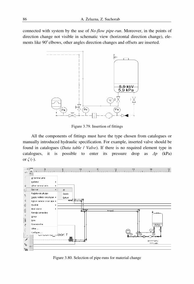
A. Żelazna, Z. Suchorab 86
connected with system by the use of No-flow pipe-run. Moreover, in the points of
direction change not visible in schematic view (horizontal direction change), ele-
ments like 90o elbows, other angles direction changes and offsets are inserted.
Figure 3.79. Insertion of fittings
All the components of fittings must have the type chosen from catalogues or
manually introduced hydraulic specification. For example, inserted valve should be
found in catalogues (Data table / Valve). If there is no required element type in
catalogues, it is possible to enter its pressure drop as ∆p (kPa)
or ζ (-).
Figure 3.80. Selection of pipe-runs for material change
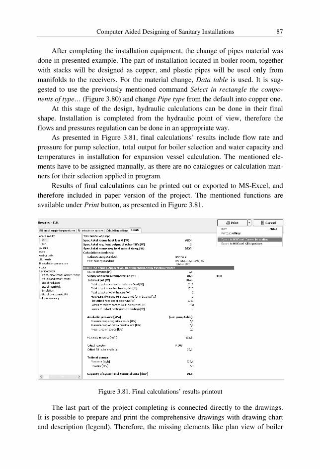
Computer Aided Designing of Sanitary Installations 87
After completing the installation equipment, the change of pipes material was
done in presented example. The part of installation located in boiler room, together
with stacks will be designed as copper, and plastic pipes will be used only from
manifolds to the receivers. For the material change, Data table is used. It is sug-
gested to use the previously mentioned command Select in rectangle the compo-
nents of type… (Figure 3.80) and change Pipe type from the default into copper one.
At this stage of the design, hydraulic calculations can be done in their final
shape. Installation is completed from the hydraulic point of view, therefore the
flows and pressures regulation can be done in an appropriate way.
As presented in Figure 3.81, final calculations’ results include flow rate and
pressure for pump selection, total output for boiler selection and water capacity and
temperatures in installation for expansion vessel calculation. The mentioned ele-
ments have to be assigned manually, as there are no catalogues or calculation man-
ners for their selection applied in program.
Results of final calculations can be printed out or exported to MS-Excel, and
therefore included in paper version of the project. The mentioned functions are
available under Print button, as presented in Figure 3.81.
Figure 3.81. Final calculations’ results printout
The last part of the project completing is connected directly to the drawings.
It is possible to prepare and print the comprehensive drawings with drawing chart
and description (legend). Therefore, the missing elements like plan view of boiler
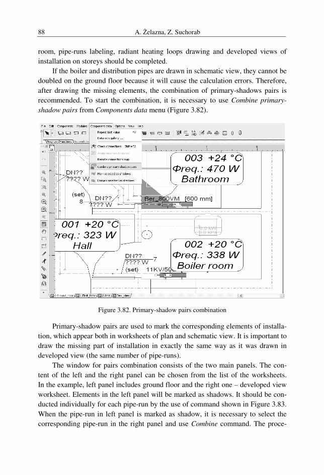
A. Żelazna, Z. Suchorab 88
room, pipe-runs labeling, radiant heating loops drawing and developed views of
installation on storeys should be completed.
If the boiler and distribution pipes are drawn in schematic view, they cannot be
doubled on the ground floor because it will cause the calculation errors. Therefore,
after drawing the missing elements, the combination of primary-shadows pairs is
recommended. To start the combination, it is necessary to use Combine primary-
shadow pairs from Components data menu (Figure 3.82).
Figure 3.82. Primary-shadow pairs combination
Primary-shadow pairs are used to mark the corresponding elements of installa-
tion, which appear both in worksheets of plan and schematic view. It is important to
draw the missing part of installation in exactly the same way as it was drawn in
developed view (the same number of pipe-runs).
The window for pairs combination consists of the two main panels. The con-
tent of the left and the right panel can be chosen from the list of the worksheets.
In the example, left panel includes ground floor and the right one – developed view
worksheet. Elements in the left panel will be marked as shadows. It should be con-
ducted individually for each pipe-run by the use of command shown in Figure 3.83.
When the pipe-run in left panel is marked as shadow, it is necessary to select the
corresponding pipe-run in the right panel and use Combine command. The proce-
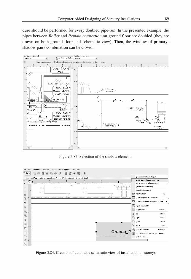
Computer Aided Designing of Sanitary Installations 89
dure should be performed for every doubled pipe-run. In the presented example, the
pipes between Boiler and Remote connection on ground floor are doubled (they are
drawn on both ground floor and schematic view). Then, the window of primary-
shadow pairs combination can be closed.
Figure 3.83. Selection of the shadow elements
Figure 3.84. Creation of automatic schematic view of installation on storeys
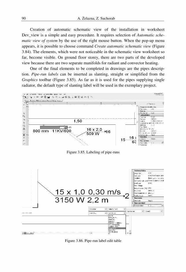
A. Żelazna, Z. Suchorab 90
Creation of automatic schematic view of the installation in worksheet
Dev_view is a simple and easy procedure. It requires selection of Automatic sche-
matic view of system by the use of the right mouse button. When the pop-up menu
appears, it is possible to choose command Create automatic schematic view (Figure
3.84). The elements, which were not noticeable in the schematic view worksheet so
far, become visible. On ground floor storey, there are two parts of the developed
view because there are two separate manifolds for radiant and convector heating.
One of the final elements to be completed in drawings are the pipes descrip-
tion. Pipe-run labels can be inserted as slanting, straight or simplified from the
Graphics toolbar (Figure 3.85). As far as it is used for the pipes supplying single
radiator, the default type of slanting label will be used in the exemplary project.
Figure 3.85. Labeling of pipe-runs
Figure 3.86. Pipe-run label edit table
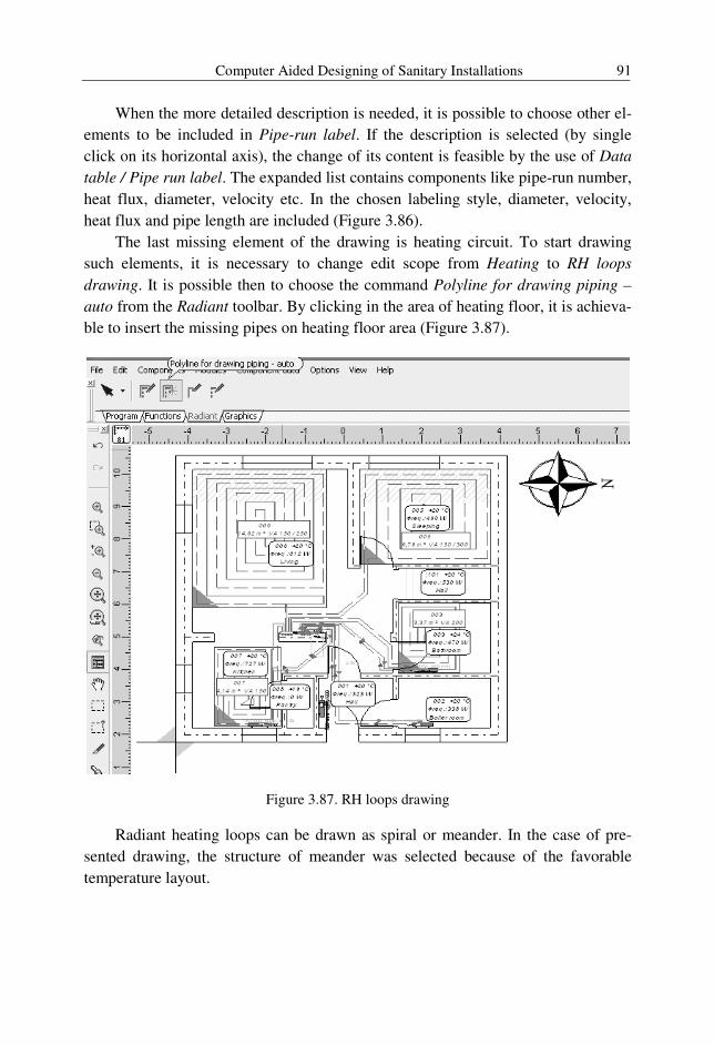
Computer Aided Designing of Sanitary Installations 91
When the more detailed description is needed, it is possible to choose other el-
ements to be included in Pipe-run label. If the description is selected (by single
click on its horizontal axis), the change of its content is feasible by the use of Data
table / Pipe run label. The expanded list contains components like pipe-run number,
heat flux, diameter, velocity etc. In the chosen labeling style, diameter, velocity,
heat flux and pipe length are included (Figure 3.86).
The last missing element of the drawing is heating circuit. To start drawing
such elements, it is necessary to change edit scope from Heating to RH loops
drawing. It is possible then to choose the command Polyline for drawing piping –
auto from the Radiant toolbar. By clicking in the area of heating floor, it is achieva-
ble to insert the missing pipes on heating floor area (Figure 3.87).
Figure 3.87. RH loops drawing
Radiant heating loops can be drawn as spiral or meander. In the case of pre-
sented drawing, the structure of meander was selected because of the favorable
temperature layout.
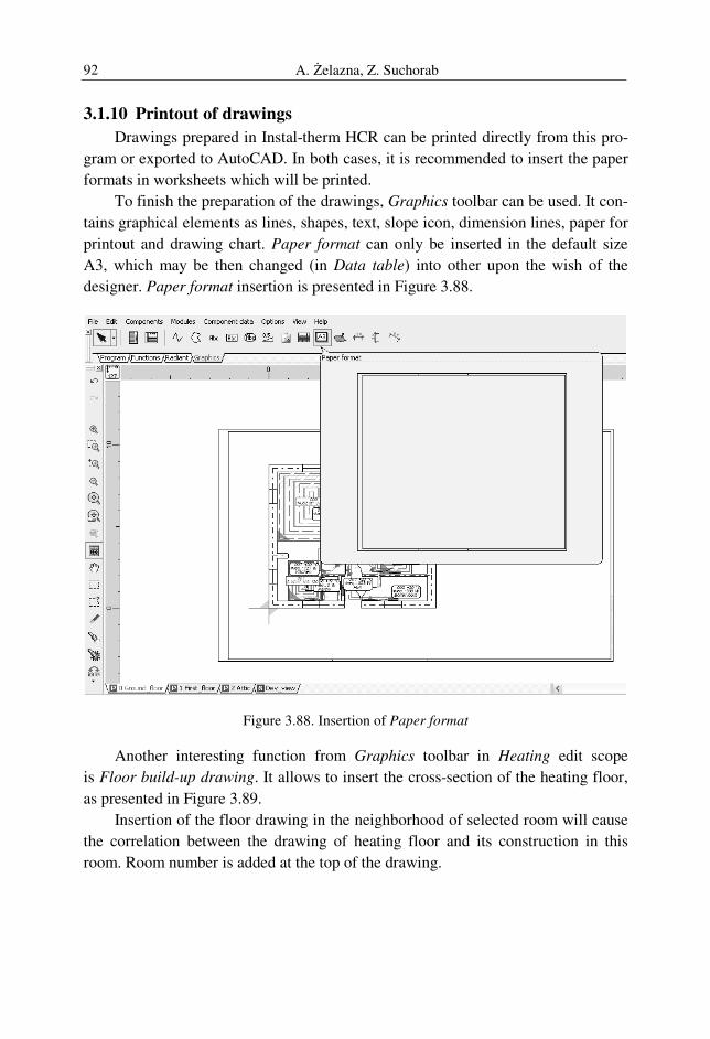
A. Żelazna, Z. Suchorab 92
3.1.10 Printout of drawings
Drawings prepared in Instal-therm HCR can be printed directly from this pro-
gram or exported to AutoCAD. In both cases, it is recommended to insert the paper
formats in worksheets which will be printed.
To finish the preparation of the drawings, Graphics toolbar can be used. It con-
tains graphical elements as lines, shapes, text, slope icon, dimension lines, paper for
printout and drawing chart. Paper format can only be inserted in the default size
A3, which may be then changed (in Data table) into other upon the wish of the
designer. Paper format insertion is presented in Figure 3.88.
Figure 3.88. Insertion of Paper format
Another interesting function from Graphics toolbar in Heating edit scope
is Floor build-up drawing. It allows to insert the cross-section of the heating floor,
as presented in Figure 3.89.
Insertion of the floor drawing in the neighborhood of selected room will cause
the correlation between the drawing of heating floor and its construction in this
room. Room number is added at the top of the drawing.
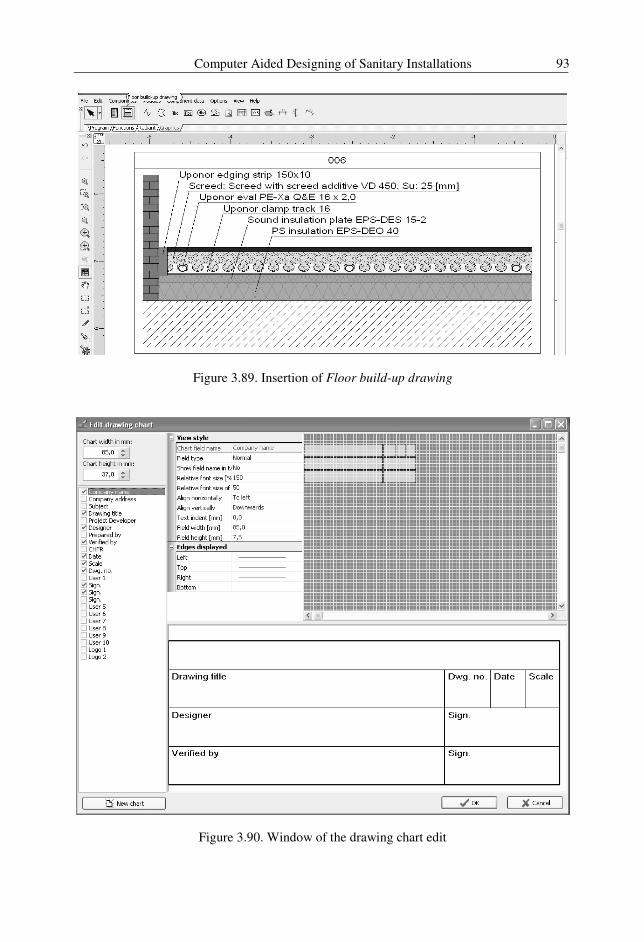
Computer Aided Designing of Sanitary Installations 93
Figure 3.89. Insertion of Floor build-up drawing
Figure 3.90. Window of the drawing chart edit
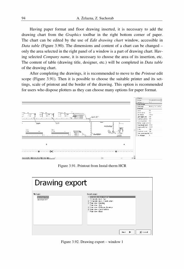
A. Żelazna, Z. Suchorab 94
Having paper format and floor drawing inserted, it is necessary to add the
drawing chart from the Graphics toolbar in the right bottom corner of paper.
The chart can be edited by the use of Edit drawing chart window, accessible in
Data table (Figure 3.90). The dimensions and content of a chart can be changed –
only the area selected in the right panel of a window is a part of drawing chart. Hav-
ing selected Company name, it is necessary to choose the area of its insertion, etc.
The content of table (drawing title, designer, etc.) will be completed in Data table
of the drawing chart.
After completing the drawings, it is recommended to move to the Printout edit
scope (Figure 3.91). Then it is possible to choose the suitable printer and its set-
tings, scale of printout and the border of the drawing. This option is recommended
for users who dispose plotters as they can choose many options for paper format.
Figure 3.91. Printout from Instal-therm HCR
Figure 3.92. Drawing export – window 1
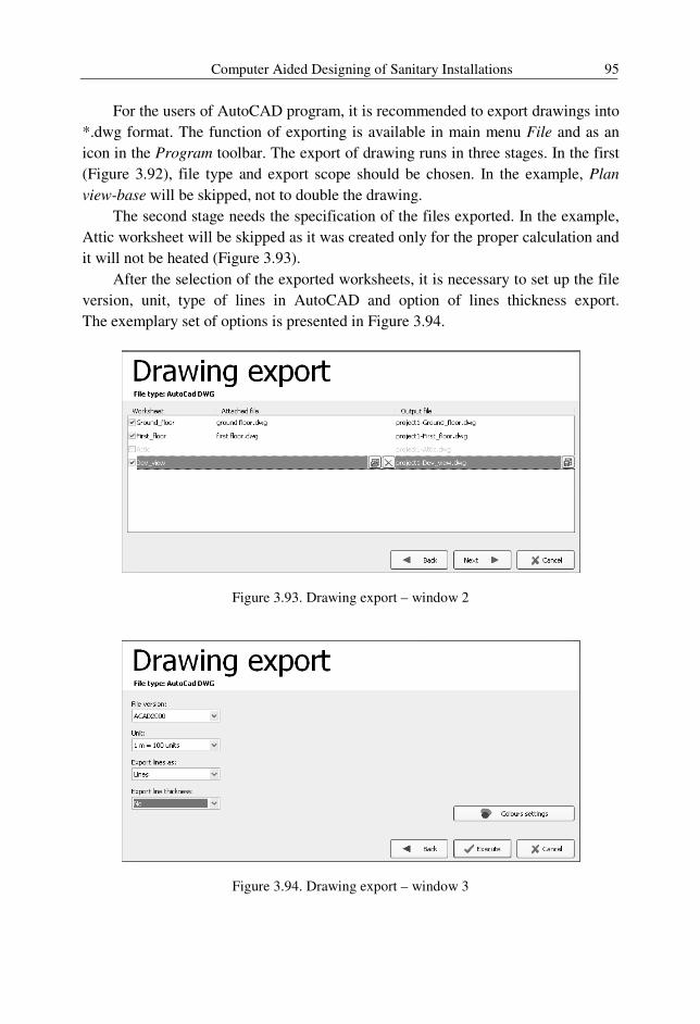
Computer Aided Designing of Sanitary Installations 95
For the users of AutoCAD program, it is recommended to export drawings into
*.dwg format. The function of exporting is available in main menu File and as an
icon in the Program toolbar. The export of drawing runs in three stages. In the first
(Figure 3.92), file type and export scope should be chosen. In the example, Plan
view-base will be skipped, not to double the drawing.
The second stage needs the specification of the files exported. In the example,
Attic worksheet will be skipped as it was created only for the proper calculation and
it will not be heated (Figure 3.93).
After the selection of the exported worksheets, it is necessary to set up the file
version, unit, type of lines in AutoCAD and option of lines thickness export.
The exemplary set of options is presented in Figure 3.94.
Figure 3.93. Drawing export – window 2
Figure 3.94. Drawing export – window 3
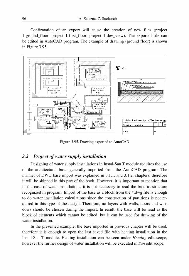
A. Żelazna, Z. Suchorab 96
Confirmation of an export will cause the creation of new files (project
1-ground_floor, project 1-first_floor, project 1-dev_view). The exported file can
be edited in AutoCAD program. The example of drawing (ground floor) is shown
in Figure 3.95.
Figure 3.95. Drawing exported to AutoCAD
3.2 Project of water supply installation
Designing of water supply installations in Instal-San T module requires the use
of the architectural base, generally imported from the AutoCAD program. The
manner of DWG base import was explained in 3.1.1. and 3.1.2. chapters, therefore
it will be skipped in this part of the book. However, it is important to mention that
in the case of water installations, it is not necessary to read the base as structure
recognized in program. Import of the base as a block from the *.dwg file is enough
to do water installation calculations since the construction of partitions is not re-
quired in this type of the design. Therefore, no layers with walls, doors and win-
dows should be chosen during the import. In result, the base will be read as the
block of elements which cannot be edited, but it can be used for drawing of the
water installation.
In the presented example, the base imported in previous chapter will be used,
therefore it is enough to open the last saved file with heating installation in the
Instal-San T module. Heating installation can be seen under Heating edit scope,
however the further design of water installation will be executed in San edit scope.
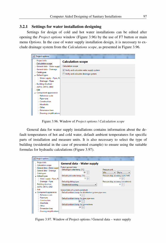
Computer Aided Designing of Sanitary Installations 97
3.2.1 Settings for water installation designing
Settings for design of cold and hot water installations can be edited after
opening the Project options window (Figure 3.96) by the use of F7 button or main
menu Options. In the case of water supply installation design, it is necessary to ex-
clude drainage system from the Calculations scope, as presented in Figure 3.96.
Figure 3.96. Window of Project options / Calculation scope
General data for water supply installations contains information about the de-
fault temperatures of hot and cold water, default ambient temperatures for specific
parts of installation and measure units. It is also necessary to select the type of
building (residential in the case of presented example) to ensure using the suitable
formulas for hydraulic calculations (Figure 3.97).
Figure 3.97. Window of Project options / General data – water supply
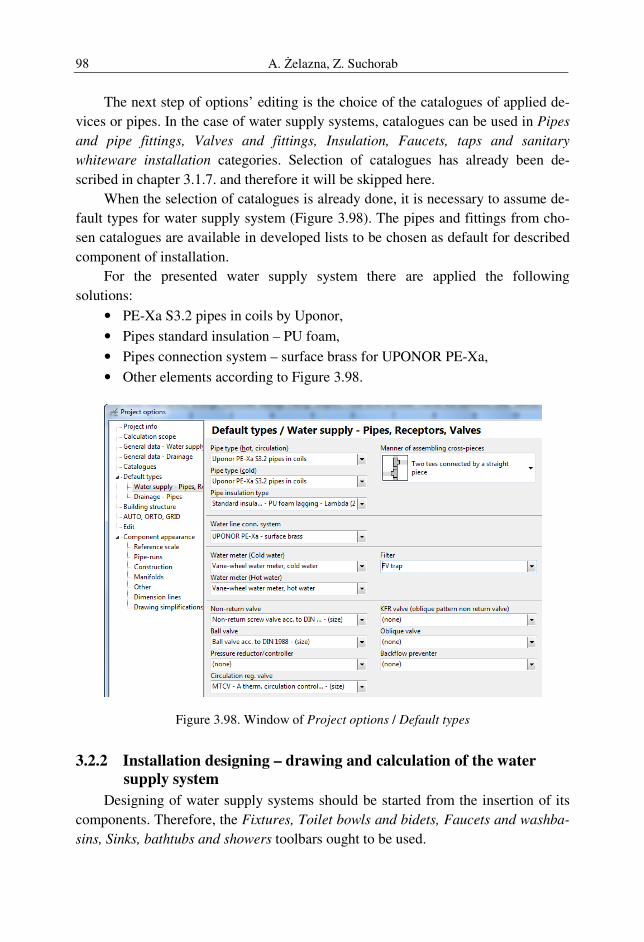
A. Żelazna, Z. Suchorab 98
The next step of options’ editing is the choice of the catalogues of applied de-
vices or pipes. In the case of water supply systems, catalogues can be used in Pipes
and pipe fittings, Valves and fittings, Insulation, Faucets, taps and sanitary
whiteware installation categories. Selection of catalogues has already been de-
scribed in chapter 3.1.7. and therefore it will be skipped here.
When the selection of catalogues is already done, it is necessary to assume de-
fault types for water supply system (Figure 3.98). The pipes and fittings from cho-
sen catalogues are available in developed lists to be chosen as default for described
component of installation.
For the presented water supply system there are applied the following
solutions:
• PE-Xa S3.2 pipes in coils by Uponor,
• Pipes standard insulation – PU foam,
• Pipes connection system – surface brass for UPONOR PE-Xa,
• Other elements according to Figure 3.98.
Figure 3.98. Window of Project options / Default types
3.2.2 Installation designing – drawing and calculation of the water
supply system
Designing of water supply systems should be started from the insertion of its
components. Therefore, the Fixtures, Toilet bowls and bidets, Faucets and washba-
sins, Sinks, bathtubs and showers toolbars ought to be used.
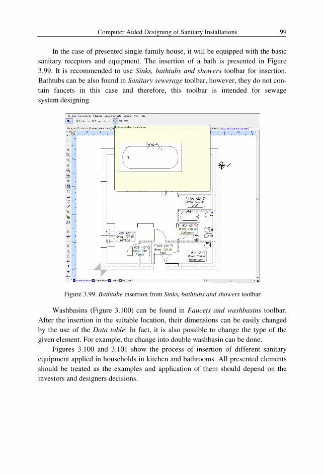
Computer Aided Designing of Sanitary Installations 99
In the case of presented single-family house, it will be equipped with the basic
sanitary receptors and equipment. The insertion of a bath is presented in Figure
3.99. It is recommended to use Sinks, bathtubs and showers toolbar for insertion.
Bathtubs can be also found in Sanitary sewerage toolbar, however, they do not con-
tain faucets in this case and therefore, this toolbar is intended for sewage
system designing.
Figure 3.99. Bathtube insertion from Sinks, bathtubs and showers toolbar
Washbasins (Figure 3.100) can be found in Faucets and washbasins toolbar.
After the insertion in the suitable location, their dimensions can be easily changed
by the use of the Data table. In fact, it is also possible to change the type of the
given element. For example, the change into double washbasin can be done.
Figures 3.100 and 3.101 show the process of insertion of different sanitary
equipment applied in households in kitchen and bathrooms. All presented elements
should be treated as the examples and application of them should depend on the
investors and designers decisions.
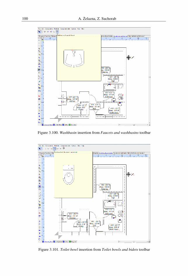
A. Żelazna, Z. Suchorab 100
Figure 3.100. Washbasin insertion from Faucets and washbasins toolbar
Figure 3.101. Toilet bowl insertion from Toilet bowls and bidets toolbar
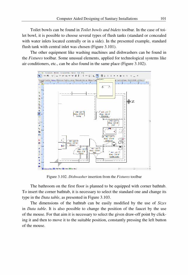
Computer Aided Designing of Sanitary Installations 101
Toilet bowls can be found in Toilet bowls and bidets toolbar. In the case of toi-
let bowl, it is possible to choose several types of flush tanks (standard or concealed
with water inlets located centrally or in a side). In the presented example, standard
flush tank with central inlet was chosen (Figure 3.101).
The other equipment like washing machines and dishwashers can be found in
the Fixtures toolbar. Some unusual elements, applied for technological systems like
air conditioners, etc., can be also found in the same place (Figure 3.102).
Figure 3.102. Dishwasher insertion from the Fixtures toolbar
The bathroom on the first floor is planned to be equipped with corner bathtub.
To insert the corner bathtub, it is necessary to select the standard one and change its
type in the Data table, as presented in Figure 3.103.
The dimensions of the bathtub can be easily modified by the use of Sizes
in Data table. It is also possible to change the position of the faucet by the use
of the mouse. For that aim it is necessary to select the given draw-off point by click-
ing it and then to move it to the suitable position, constantly pressing the left button
of the mouse.
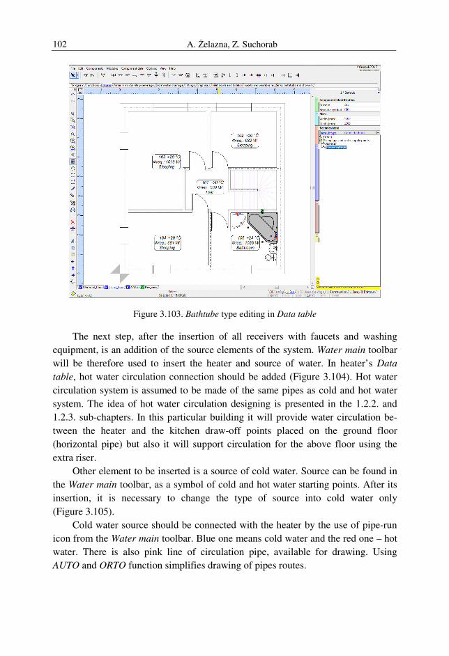
A. Żelazna, Z. Suchorab 102
Figure 3.103. Bathtube type editing in Data table
The next step, after the insertion of all receivers with faucets and washing
equipment, is an addition of the source elements of the system. Water main toolbar
will be therefore used to insert the heater and source of water. In heater’s Data
table, hot water circulation connection should be added (Figure 3.104). Hot water
circulation system is assumed to be made of the same pipes as cold and hot water
system. The idea of hot water circulation designing is presented in the 1.2.2. and
1.2.3. sub-chapters. In this particular building it will provide water circulation be-
tween the heater and the kitchen draw-off points placed on the ground floor
(horizontal pipe) but also it will support circulation for the above floor using the
extra riser.
Other element to be inserted is a source of cold water. Source can be found in
the Water main toolbar, as a symbol of cold and hot water starting points. After its
insertion, it is necessary to change the type of source into cold water only
(Figure 3.105).
Cold water source should be connected with the heater by the use of pipe-run
icon from the Water main toolbar. Blue one means cold water and the red one – hot
water. There is also pink line of circulation pipe, available for drawing. Using
AUTO and ORTO function simplifies drawing of pipes routes.
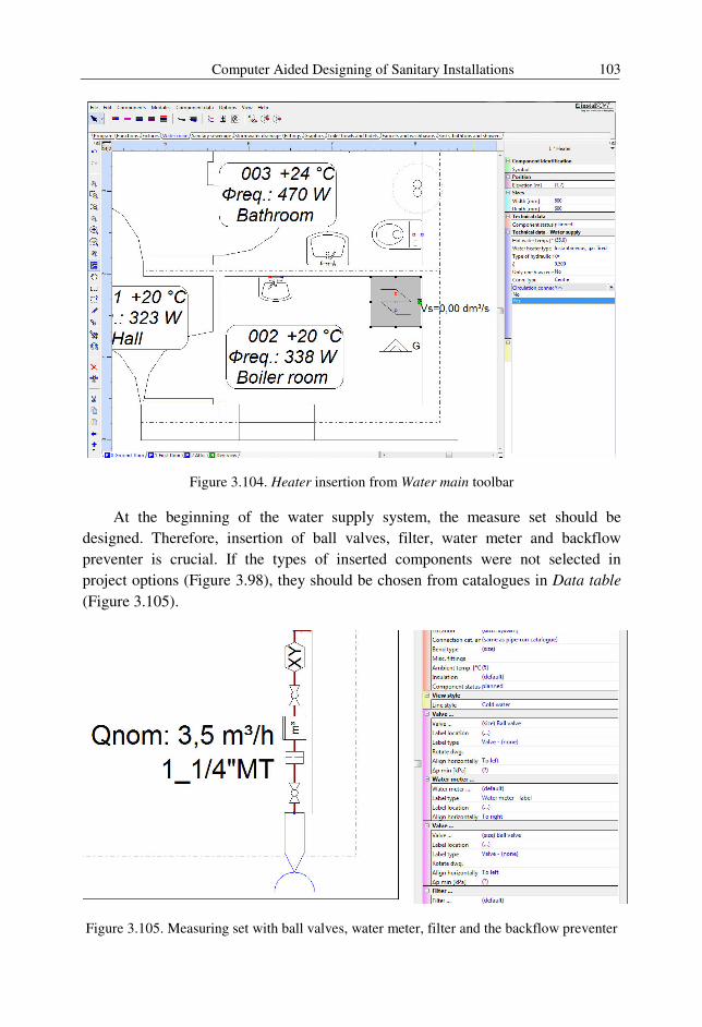
Computer Aided Designing of Sanitary Installations 103
Figure 3.104. Heater insertion from Water main toolbar
At the beginning of the water supply system, the measure set should be
designed. Therefore, insertion of ball valves, filter, water meter and backflow
preventer is crucial. If the types of inserted components were not selected in
project options (Figure 3.98), they should be chosen from catalogues in Data table
(Figure 3.105).
Figure 3.105. Measuring set with ball valves, water meter, filter and the backflow preventer
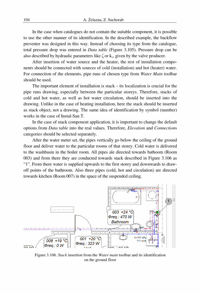
A. Żelazna, Z. Suchorab 104
In the case when catalogues do not contain the suitable component, it is possible
to use the other manner of its identification. In the described example, the backflow
preventer was designed in this way. Instead of choosing its type from the catalogue,
total pressure drop was entered in Data table (Figure 3.105). Pressure drop can be
also described by hydraulic parameters like ζ or kv, given by the valve producer.
After insertion of water source and the heater, the rest of installation compo-
nents should be connected with sources of cold (installation) and hot (heater) water.
For connection of the elements, pipe runs of chosen type from Water Main toolbar
should be used.
The important element of installation is stack – its localization is crucial for the
pipe runs drawing, especially between the particular storeys. Therefore, stacks of
cold and hot water, as well as hot water circulation, should be inserted into the
drawing. Unlike in the case of heating installation, here the stack should be inserted
as stack object, not a drawing. The same idea of identification by symbol (number)
works in the case of Instal-San T.
In the case of stack component application, it is important to change the default
options from Data table into the real values. Therefore, Elevation and Connections
categories should be selected separately.
After the water meter set, the pipes vertically go below the ceiling of the ground
floor and deliver water to the particular rooms of that storey. Cold water is delivered
to the washbasin in the boiler room. All pipes ale directed towards bathoom (Room
003) and from there they are conducted towards stack described in Figure 3.106 as
“1”. From there water is supplied upwards to the first storey and downwards to draw-
off points of the bathroom. Also three pipes (cold, hot and circulation) are directed
towards kitchen (Room 007) in the space of the suspended ceiling.
Figure 3.106. Stack insertion from the Water main toolbar and its identification on the ground floor
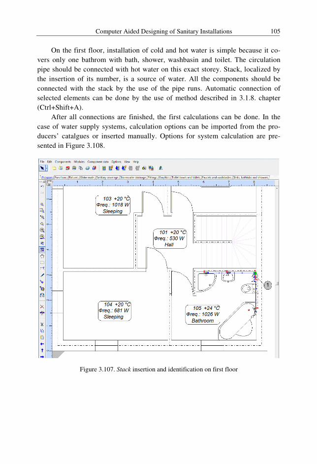
Computer Aided Designing of Sanitary Installations 105
On the first floor, installation of cold and hot water is simple because it co-
vers only one bathrom with bath, shower, washbasin and toilet. The circulation
pipe should be connected with hot water on this exact storey. Stack, localized by
the insertion of its number, is a source of water. All the components should be
connected with the stack by the use of the pipe runs. Automatic connection of
selected elements can be done by the use of method described in 3.1.8. chapter
(Ctrl+Shift+A).
After all connections are finished, the first calculations can be done. In the
case of water supply systems, calculation options can be imported from the pro-
ducers’ catalgues or inserted manually. Options for system calculation are pre-
sented in Figure 3.108.
Figure 3.107. Stack insertion and identification on first floor
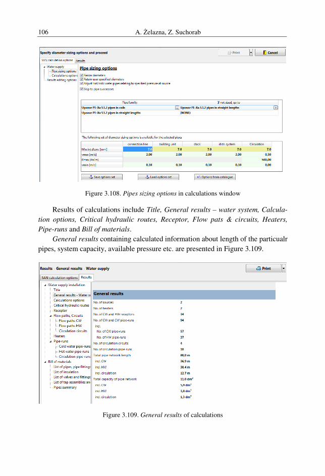
A. Żelazna, Z. Suchorab 106
Figure 3.108. Pipes sizing options in calculations window
Results of calculations include Title, General results – water system, Calcula-
tion options, Critical hydraulic routes, Receptor, Flow pats & circuits, Heaters,
Pipe-runs and Bill of materials.
General results containing calculated information about length of the particualr
pipes, system capacity, available pressure etc. are presented in Figure 3.109.
Figure 3.109. General results of calculations
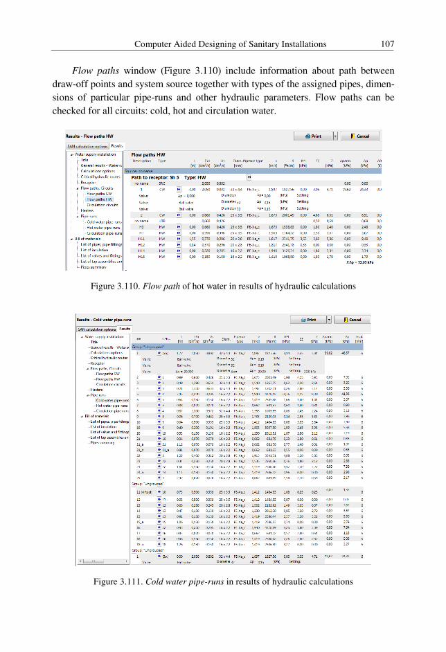
Computer Aided Designing of Sanitary Installations 107
Flow paths window (Figure 3.110) include information about path between
draw-off points and system source together with types of the assigned pipes, dimen-
sions of particular pipe-runs and other hydraulic parameters. Flow paths can be
checked for all circuits: cold, hot and circulation water.
Figure 3.110. Flow path of hot water in results of hydraulic calculations
Figure 3.111. Cold water pipe-runs in results of hydraulic calculations
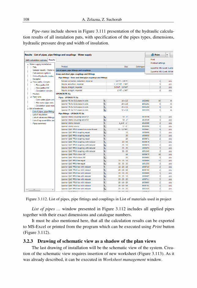
A. Żelazna, Z. Suchorab 108
Pipe-runs include shown in Figure 3.111 presentation of the hydraulic calcula-
tion results of all instalation pats, with specification of the pipes types, dimensions,
hydraulic pressure drop and width of insulation.
Figure 3.112. List of pipes, pipe fittings and couplings in List of materials used in project
List of pipes … window presented in Figure 3.112 includes all applied pipes
together with their exact dimensions and catalogue numbers.
It must be also mentioned here, that all the calculation results can be exported
to MS-Excel or printed from the program which can be executed using Print button
(Figure 3.112).
3.2.3 Drawing of schematic view as a shadow of the plan views
The last drawing of installation will be the schematic view of the system. Crea-
tion of the schematic view requires insertion of new worksheet (Figure 3.113). As it
was already described, it can be executed in Worksheet management window.
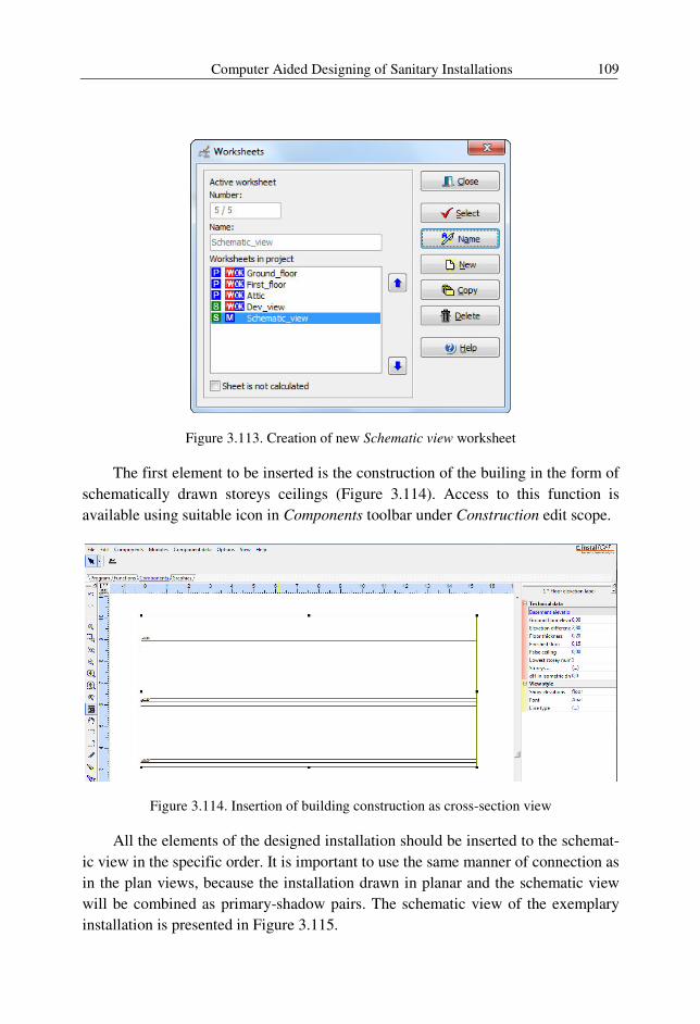
Computer Aided Designing of Sanitary Installations 109
Figure 3.113. Creation of new Schematic view worksheet
The first element to be inserted is the construction of the builing in the form of
schematically drawn storeys ceilings (Figure 3.114). Access to this function is
available using suitable icon in Components toolbar under Construction edit scope.
Figure 3.114. Insertion of building construction as cross-section view
All the elements of the designed installation should be inserted to the schemat-
ic view in the specific order. It is important to use the same manner of connection as
in the plan views, because the installation drawn in planar and the schematic view
will be combined as primary-shadow pairs. The schematic view of the exemplary
installation is presented in Figure 3.115.
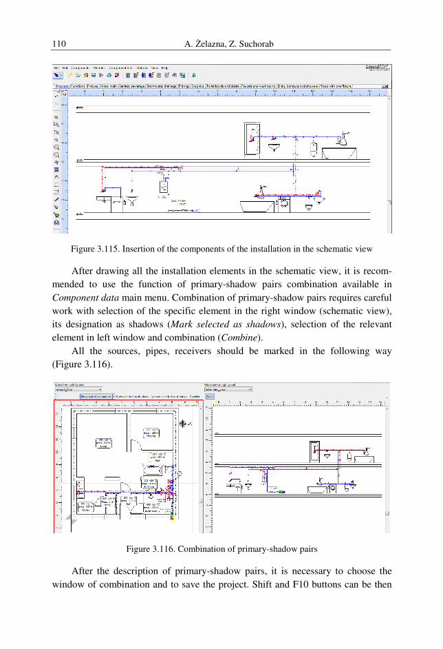
A. Żelazna, Z. Suchorab 110
Figure 3.115. Insertion of the components of the installation in the schematic view
After drawing all the installation elements in the schematic view, it is recom-
mended to use the function of primary-shadow pairs combination available in
Component data main menu. Combination of primary-shadow pairs requires careful
work with selection of the specific element in the right window (schematic view),
its designation as shadows (Mark selected as shadows), selection of the relevant
element in left window and combination (Combine).
All the sources, pipes, receivers should be marked in the following way
(Figure 3.116).
Figure 3.116. Combination of primary-shadow pairs
After the description of primary-shadow pairs, it is necessary to choose the
window of combination and to save the project. Shift and F10 buttons can be then
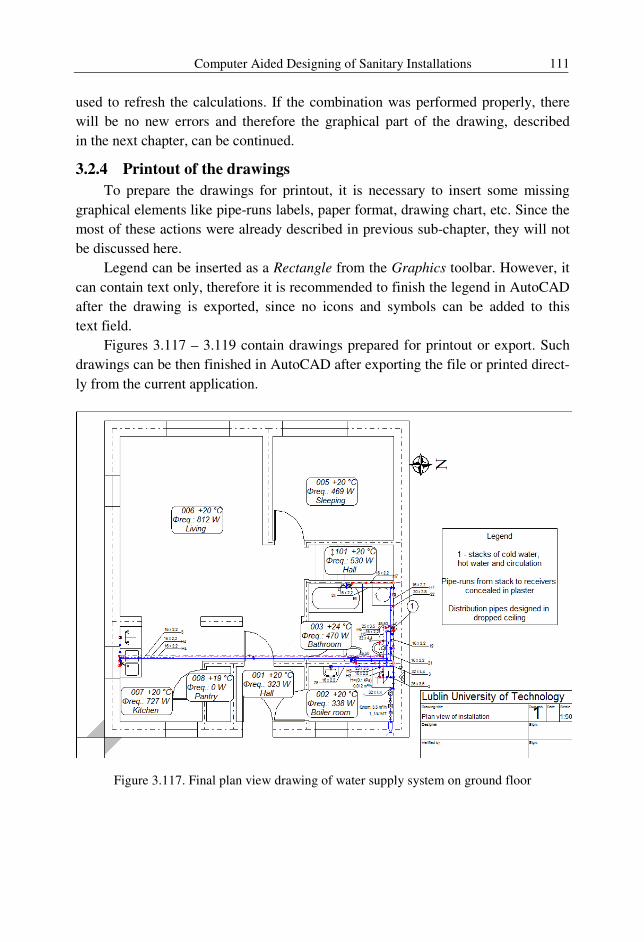
Computer Aided Designing of Sanitary Installations 111
used to refresh the calculations. If the combination was performed properly, there
will be no new errors and therefore the graphical part of the drawing, described
in the next chapter, can be continued.
3.2.4 Printout of the drawings
To prepare the drawings for printout, it is necessary to insert some missing
graphical elements like pipe-runs labels, paper format, drawing chart, etc. Since the
most of these actions were already described in previous sub-chapter, they will not
be discussed here.
Legend can be inserted as a Rectangle from the Graphics toolbar. However, it
can contain text only, therefore it is recommended to finish the legend in AutoCAD
after the drawing is exported, since no icons and symbols can be added to this
text field.
Figures 3.117 – 3.119 contain drawings prepared for printout or export. Such
drawings can be then finished in AutoCAD after exporting the file or printed direct-
ly from the current application.
Figure 3.117. Final plan view drawing of water supply system on ground floor
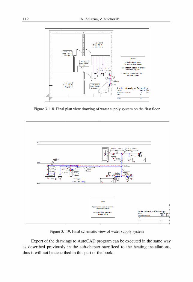
A. Żelazna, Z. Suchorab 112
Figure 3.118. Final plan view drawing of water supply system on the first floor
Figure 3.119. Final schematic view of water supply system
Export of the drawings to AutoCAD program can be executed in the same way
as described previously in the sub-chapter sacrificed to the heating installations,
thus it will not be described in this part of the book.
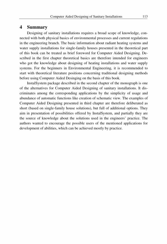
Computer Aided Designing of Sanitary Installations 113
4 Summary
Designing of sanitary installations requires a broad scope of knowledge, con-
nected with both physical basics of environmental processes and current regulations
in the engineering branch. The basic information about radiant heating systems and
water supply installations for single-family houses presented in the theoretical part
of this book can be treated as brief foreword for Computer Aided Designing. De-
scribed in the first chapter theoretical basics are therefore intended for engineers
who got the knowledge about designing of heating installations and water supply
systems. For the beginners in Environmental Engineering, it is recommended to
start with theoretical literature positions concerning traditional designing methods
before using Computer Aided Desinging on the basis of this book.
InstalSystem package described in the second chapter of the monograph is one
of the alternatives for Computer Aided Designing of sanitary installations. It dis-
criminates among the corresponding applications by the simplicity of usage and
abundance of automatic functions like creation of schematic view. The examples of
Computer Aided Designing presented in third chapter are therefore deliberated as
short (based on single-family house solutions), but full of additional options. They
aim in presentation of possibilities offered by InstalSystem, and partially they are
the source of knowledge about the solutions used in the engineers’ practice. The
authors wanted to encourage the possible users of the mentioned applications for
development of abilities, which can be achieved mostly by practice.

A. Żelazna, Z. Suchorab 114
5 References
1. Albers J., Dommel R., Montaldo – Ventsam H., Nedo H., Ubelacker E., Wa-
gner J., Systemy centralnego ogrzewania i wentylacji. Poradnik dla projektan-
tów i instalatorów, Wydawnictwo Naukowo – Techniczne, Warszawa 2007
2. Antonowicz, Instalacje budowlane, Wydawnictwo Politechniki Wrocławskiej,
Wrocław 1976
3. Balcerowska M.: Instalacje grzewcze – poradnik, Login Media Sp. z o.o., War-
szawa 2009
4. Brumbaugh J. HVAC fundamentals. Volume 1: Heating systems, furnaces and
boilers. Wiley Publishing INC, Indianapolis 2004
5. Brydak-Jeżowiecka, Nowakowski, Malinowski, Straty ciśnienia w rurach
z tworzyw sztucznych stosowanych w instalacjach wodociągowych. Gaz, Woda
i Technika Sanitarna nr 7/1994.
6. Causone, F., Olesen, B.W., Corgnati, S.P. “Floor heating and cooling combined
with displacement ventilation: Possibilities and limitations”, source title: Ener-
gy and Buildings, 2010, 2338 – 2352
7. Cholewa T., Siuta-Olcha A., Krukowski I., Rzeczywiste zużycie wody a warto-
ści przyjmowane przy projektowaniu, Polska Inżynieria Środowiska pięć lat po
wstąpieniu do Unii Europejskiej, tom 2, vol. 59 2009, p. 9-16
8. Chudzicki J. Instalacje ciepłej wody w budynkach, Wyd. Sorus, Warszawa-
Poznań 2006
9. Chudzicki J., Rozwiązania techniczne energooszczędnych instalacji wodocią-gowych i kanalizacyjnych, Energy-saving and Ecological Materials, Installa-
tions and Technology in Construction Ed. By Stanisław Fic, Biała Podlaska
2012, pp.208-219
10. Chudzicki J., Sosnowski S., Instalacje wodociągowe. Projektowanie, wykona-
nie, eksploatacja. Wyd. Seidel-Przywecki, Warszawa 2011
11. Chudzicki J., Sosnowski S., Instalacje kanalizacyjne. Projektowanie, wykona-
nie, eksploatacja. Wyd. Seidel-Przywecki, Warszawa 2009
12. Gassner A., Instalacje Sanitarne - Poradnik dla projektantów i instalatorów,
Wydawnictwa Naukowo-Techniczne, Warszawa 2008
13. Gwoździej-Mazur J., Tuz P.K., Prognozowanie zużycia wody w mieszkalnic-
twie, Monografie Komitetu Inżynierii Środowiska PAN, 2002, vol. 11, p. 391-
396
14. Jeżowiecki J., Nowakowski E., Określanie średnic przewodów w instalacjach
wodociągowych budynków mieszkalnych, „Nowoczesne rozwiązania w inży-
nierii i ochronie środowiska”, Tom I, Wrocław 2011, p.287-292.

Computer Aided Designing of Sanitary Installations 115
15. Koczyk H., Antoniewicz B., Nowoczesne wyposażenie techniczne domu jedno-
rodzinnego. Instalacje sanitarne i grzewcze, Państwowe Wydawnictwo Rolni-
cze i Leśne, Poznań 2004
16. Kowalczyk M., Nowoczesne systemy grzewcze, Wydawnictwo SOLAREN-
BIS, Gdańsk 2002
17. Krygier K., Klinke T. Sewerynik J. Ogrzewnictwo wentylacja klimatyzacja.
Wydawnicwto WSiP, Warszawa 2007
18. Kwiatkowski J., Cholewa L., Centralne ogrzewanie. Pomoce projektanta, Wy-
dawnictwo Arkady, Warszawa 1980
19. Kwiatkowski J., Cholewa L., Pomoce do projektowania urządzeń ogrzewczych,
tom II, Wydawnictwo Politechniki Lubelskiej, Lublin 1978
20. Maier T., Tejchman J., Modelowanie komfortu termiczno – wilgotnościowego
i psychofizycznego w nowoczesnych domach mieszkalnych, Wydawnictwo Po-
litechniki Gdańskiej, Gdańsk 2006
21. Muszyński P., Projektowanie cyrkulacji w instalacjach c.w.u. metodą z równo-
ważeniem dynamicznym, III Konferencja naukowo-techniczna, Instalacje wo-
dociągowe i kanalizacyjne, Projektowanie-Wykonawstwo-Eksploatacja, War-
szawa-Dębe 2009, p.42-55.
22. Nantka M. Ogrzewnictwo i ciepłownictwo tom I, Wydawnictwo Politechniki
Śląskiej, Gliwice 2010
23. Nantka M. Ogrzewnictwo i ciepłownictwo, tom II, Wydawnictwo Politechniki
Śląskiej, Gliwice 2006
24. Nowicki J., Chmielewski A., Ogrzewanie podłogowe, Wydawnictwo INSTAL,
Warszawa 1995
25. Orłowska-Szostak M., Orłowski R., Model hydrodynamiczny cyrkulacji w in-
stalacjach c.w.u., Instalacje wodociągowe i kanalizacyjne - projektowanie, wy-
konanie i eksploracja, Warszawa-Dębe 2011, p. 189-206
26. Orłowska-Szostak M., Wyznaczanie przepływów obliczeniowych w instala-
cjach wodociągowych budynków mieszkalnych wielorodzinnych, Instalacje
wodociągowe i kanalizacyjne - projektowanie, wykonanie i eksploracja, War-
szawa-Dębe 2011, p. 67-83
27. Oszczak W., Jak taniej ogrzać dom, Wydawnictwa Komunikacji i Łączności,
Warszawa 2005
28. Panas J. (red), Nowy Poradnik majstra budowlanego, Wyd. Arkady, Warszawa
2011
29. Rosiński M., Spik Z., Teoretyczne i doświadczalne badania cieplnych właści-
wości grzejnika podłogowego w warunkach nieustalonych, Polska Inżynieria
Środowiska pięć lat po wstąpieniu do Unii Europejskiej, tom 2, vol. 59 2009,
p. 179-185
A. Żelazna, Z. Suchorab 116
30. Skiba J., Wpływ zaworów antyskażeniowych na opory przepływu w instala-
cjach wodociągowych, Instalacje wodociągowe i kanalizacyjne - projektowa-
nie, wykonanie i eksploracja, Warszawa-Dębe 2011, p. 93-98
31. Sosnowski, Tabernacki, Chudzicki, Instalacje wodociągowe i kanalizacyjne,
Wyd. Instalator Polski, Warszawa 2000
32. Widomski M.K., Musz A., Iwanek M., Strata ciśnienia w zaworze antyskaże-
niowym - badania laboratoryjne i modelowe, Instalacje wodociągowe i kanali-
zacyjne - projektowanie, wykonanie i eksploracja, Warszawa-Dębe 2011,
p. 99-112
Standards and Regulations
33. EN ISO 6946:2007 Building Components or Building Elements - Calculation of
Thermal Transmittance
34. Regulation of the Polish Minister of Infrastructure dated 12 April 2002 on tech-
nical requirements which have to be met by buildings and their situation (Jour-
nal of Laws - Dz. U. Nr 75, item 690 with subsequent amendments),
35. PN-92/B-01706, Installations for water supply. Design.
36. PN-92/B-01706/Azl: 1999
37. PN-EN1717:2003, Protection against pollution of potable water in water instal-
lations and general requirements of devices to prevent pollution by backflow
PN-EN 1264 – 1:1997 Floor heating - Systems and components - Part 1: Defi-
nitions and symbols
38. PN-EN 1264-2:2008 Water based surface embedded heating and cooling sys-
tems – Part 2: Floor heating: Prove methods for the determination of the ther-
mal output using calculation and test methods
39. PN-EN 1264-3:2009 Water based surface embedded heating and cooling sys-
tems – Part 3: Dimensioning
40. PN-EN 1264-4:2009 Water based surface embedded heating and cooling sys-
tems – Part 4: Installation
41. PN-EN 1264-5:2008 Water based surface embedded heating and cooling sys-
tems - Part 5: Heating and cooling surfaces embedded in floors, ceilings and
walls - Determination of the thermal output
42. PN-EN 12831:2006 Heating systems in buildings. Method for calculation of the
design heat load.
43. PN-EN 806-3:2006 – Specifications for installations inside buildings conveying
water for human consumption – Part 3: Pipe sizing – Simplified method.

Computer Aided Designing of Sanitary Installations 117
Internet resources:
44. Hepworth. Ogrzewanie podłogowe. Poradnik, www.hep2odlah2o.pl, 2009
45. Ogrzewanie podłogowe z rur wielowarstwowych systemu KISAN
(www.kisan.pl) Poradnik projektanta 2006 – Systemy instalacji ogrzewania
płaszczyznowego Uponor (www.uponor.com.pl), 2009
46. Uponor - Lessons to programs Instal-therm 4 HCR, Instal-h&e 4, Instal-san 4 T
and Instal-mat 4, www.instalsoft.com.pl, 2011