Embed Size (px)
Citation preview
COMPUTER-AIDED METHODS FOR ANALYSIS AND SYNTHESIS
OF SUPERSONIC CRUISE AIRCRAFT STRUCTURES
Gary L. Giles
NASA Langley Research Center
SUMMARY
The design and analysis of proposed supersonic cruise aircraft structures has required extensive use and new development of computer-aided methods. This paper reviews such computer-aided methods which have been and are being developed by Langley Research Center in-house work and by related grants and contracts. Synthesis methods to size structural members to meet strength and stiffness ('flutter) requirements have been emphasized in this work and are described. Because of the strong interaction among the aerodynamic loads, structural stiffness, and member sizes of supersonic cruise aircraft struc- tures, these methods have been combined into systems of computer programs to perform design studies. The approaches used in organizing these systems to provide efficiency, flexibility of use in an iterative process, and ease of system modification are discussed.
INTRODUCTION
Supersonic cruise aircraft tend to be large and flexible, and realistic determination of their aeroelastic behavior requires finite-element structural analysis and sophisticated steady and unsteady aerodynamic loading analysis. Such analysis methods have been developed and are available in the form of computer programs and systems for use in supersonic cruise aircraft research; see, for example, references 1 - 4. The capability to size structural members to have low structural mass and retain adequate strength and stiffness to meet all the design requirements is also important. Computer-aided methods for strut? tural synthesis are receiving considerable attention, but are not yet developed to the same level of completeness and sophistication as computer-aided struc- tural analysis methods.
The purpose of the present paper is to review computer-aided methods for structural analysis and synthesis which are being developed by Langley Research Center in-house efforts and by related grants and contracts. Methods for sizing structures to meet both strength and stiffness (flutter) requirements have been emphasized in this work and are described. Because of the strong interaction among the aerodynamic loads, structural stiffness, and member sizes of supersonic cruise aircraft structures, these methods have been combined
637
https://ntrs.nasa.gov/search.jsp?R=19770011084 2020-03-24T02:26:52+00:00Z
IIIIIII I I
into systems of computer programs to perform design studies, These programs include static and dynamic structural analyses, steady and unsteady aerody- namics, static aeroelastic and flutter analyses, and methods for sizing structural members.
The finite-element structural analysis program is the central focus in developing such a system. The "SPAR" computer program is currently being used for this purpose at Langley, and its capabilities and features are presented. The theoretical basis for SPAR is given in reference 5.
Both optimality criteria and mathematical programing procedures have been used to size structures to meet strength requirements. These procedures involve iterative processes, and the analysis and design methods have been tailored for efficient use in such processes. A methodology is described which includes these procedures and which results in simultaneous calculation of aircraft design loads and structural member sizes. Efficient analysis and reanalysis methods and approximation techniques are used with mathematical programing procedures to provide capability to size large-scale structural models to meet flutter requirements. The 'initial implementation of these methods in a pilot computer program and subsequent incorporation into SPAR is discussed.
The method of organization of these various computer programs into systems necessary for structural studies in supersonic cruise aircraft research is an important consideration in terms of time and cost required for development and ease and flexibility of use of the software product. Several approaches were used in organizing the systems described herein and their relative merits are discussed.
STRUCTURAL ANALYSIS
The emphasis in this paper is on structural synthesis or sizing. However, a fundamental part of a structural synthesis system is the program used for structural analysis. The SPAR program is currently being used for this pur- poseOat Langley, and its technical capabilities and features which facilitate its incorporation into a synthesis system are presented in this section. The actual use of SPAR in structural synthesis systems is discussed in subsequent sections.
SPAR Technical Capabilities
SPAR is a system of computer programs capable of computing static deflec- tions and stresses, natural vibration frequencies and modes, and buckling loads and mode shapes of linear finite-element simulations. The system is composed of a group of individual software "processors" which are used in a logical sequence to perform a desired analysis. Each processor is designed to perform a limited, yet distinct and complete, function. Therefore, a very high degree of modularity and user flexibility is provided by this sytem. These processors are able to communicate directly and automatically with a
638
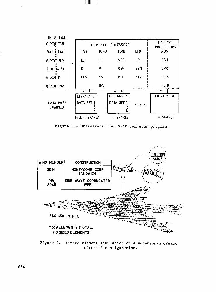
data base complex which contains the information generated by or used by other processors during a computer run. A schematic of the organization of the SPAR system is shown in figure 1.
The technical processors are operational on UNIVAC-1100 and CDC 6000/CYBER series computers. On UNIVAC systems, the processors are separate, absolute programs which are executed sequentially. On CDC systems, all the processors are designated as primary overlays-in a single, absolute program which has a zero level overlay to call the processors for execution. This zero level overlay is configured to simulate UNIVAC operation; that is, the required input stream or file is identical to that used on UNIVAC systems. This input file, shown on the left-hand side of figure 1, is designed to provide for effective interactive operation. In interactive operation, the @XQT statements 'which calls a selected processor for execution and the related input data for that processor are typed in sequentially at a user console keyboard after successive prompts from the operating system. The computational sequence is continued by using another @XQT statement to call the next desired processor.
The SPAR program is organized into two functional processor groups: tech- nical processors and utility processors. The functions of each of the SPAR processors are given in table 1. (Table 1 applies explicitly to a recent version of SPAR, denoted level 10.) The technical processors can be used in any logical sequence to perform a desired analysis such as static stress, vibration analysis, etc. A general characteristic of the technical processors is that they are very efficient with respect to both core storage and central processing time requirements. The method for handling the large, sparse matrices encountered in finite-element structural analysis in a manner to achieve this efficiency is described in reference 5. All of the technical processors make extensive use of auxiliary disk storage and operate with computer memory which is automatically allocated so that large structural simulations can be analyzed. The method used for eigenvalue and eigenvector calculations (ref. 6) makes it possible to perform a vibration analysis without first reducing the number of degrees of freedom being considered. This capability is useful in structural synthesis since a single simulation can be used for both static and dynamic calculations. Finite elements which are currently available in SPAR include axial bars, beams of general cross section, triangular and quadrilateral plates having an option to specify coupled or uncoupled membrane and bending stiffness, and quadrilateral shear panels. The provision for warping of the quadrilateral plates and an option to specify plate properties as layers in a laminate of composite materials are recent additions.
Three types of utility processors are available in SPAR; (1) the data complex utility, DCU, which is used to input, output, and manage data sets on the data complex, (2) the arithmetic utility system, AUS, which provides general matrix arithmetic capability and data set construction, and (3) on-line or off-line plotting. All of these utilities provide the user with an inter- face to the data complex. The contents and features of this data complex is discussed in the following section.
639
SPAR Data Complex
The organization of the data complex provides ready access to the data which is produced by the various processors during an analysis run. This ready access of data is an important feature since it greatly facilitates the use of SPAR in a structural synthesis system. The data complex is composed of a group of up to 20 libraries, as shown at the bottom of figure 1. Data needed to communicate among the processors during an analysis run are stored on these libraries. User input to each processor specifies the library from which the processor will retrieve needed data and the library on which the processor will store the data it generates. For many analysis runs, only a single library is used. These libraries are direct access files which contain both the data and a directory to the data. Hence, they are separate, self- contained files which can be saved without alteration on disk storage at the end of an analysis run and used in subsequent runs. These files are recognized by the computer operating system as having names of SPARLA.. . . SPARLT, as indicated on figure 1.
Each library contains data sets which are produced by the SPAR processors,. Each data set has a four-word identifying name. For example, the set of static displacements for load case 10 and boundary condition set 1 would be named STAT DISP 10 1. Through such names, the SPAR processors are able to locate and access automatically all of the information needed to perform a particular analysis. A directory, or table of contents, is stored on each' of the libraries in order to determine the size characteristics and location on disk of a data set with a specified name. An example of such a table of contents is shown in table 2.
Each line in the table denotes a data set and gives the sequence it was written on the file, the location on disk, date and time of creation, error code, size and data type information, along with the name used to reference the data set. The data complex utility provides the capability to print these tables of contents, as well as individual data sets. A COPY command is pro- vided to transfer specified data sets between libraries. This capability is very useful in saving selected information between runs. The XCOPY and the XLOAD command are used to copy data sets from the direct access libraries to sequential files and vice versa. These sequential -files can then be used to interface other programs to the SPAR system. The arithmetic utility system provides for input of user defined data sets into the library, as well as general matrix arithmetic operation on the data sets.
The flexibility of use of the technical processors and the ability to access and manage data readily in the SPAR system were very useful in developing structural synthesis or sizing systems. The next section of this paper describes two structural synthesis systems which use SPAR.
STRUCTURAL SYNTHESIS
Structural synthesis is the sizing (determination of areas or thickness) of members in a structure to satisfy a prescribed objective, for example
640
minimum mass. Design constraints such as allowable material strength and flutter boundaries, which also must be satisfied by the structure, are imposed during this process. In this section, methods are described for the synthesis of structures to meet static strength requirements and flutter requirements.
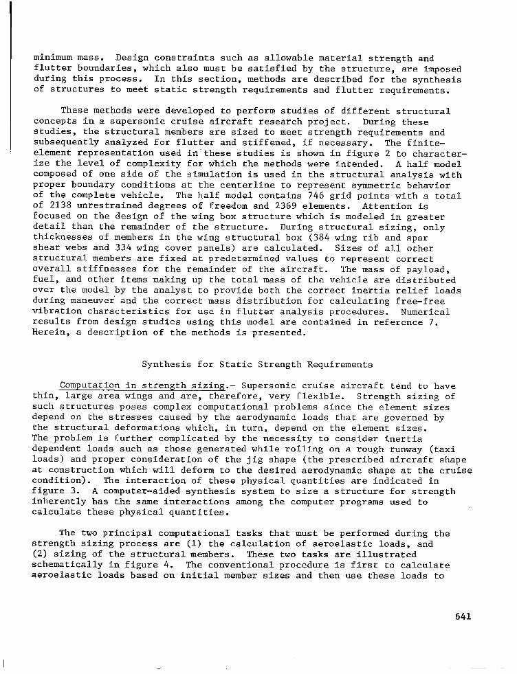
These methods were developed to perform studies of different structural concepts in a supersonic cruise aircraft research project. During these studies, the structural members are sized to meet strength requirements and subsequently analyzed for flutter and stiffened, if necessary. The finite- element representation used in-these studies is shown in figure 2 to character- ize the level of complexity for which the methods were intended. A half model composed of one side of the simulation is used in the structural analysis with proper boundary conditions at the centerline to represent symmetric behavior of the complete vehicle. The half model contains 746 grid points with a total of 2138 unrestrained degrees of freedom and 2369 elements. Attention is focused on the design of the wing box structure which is modeled in greater detail than the remainder of the structure. During structural sizing, only thicknesses of members in the wing structural box (384 wing rib and spar shear webs and 334 wing cover panels) are calculated. Sizes of all other structural members.are fixed at predetermined values to represent correct overall stiffnesses for the remainder of the aircraft. The mass of payload, fuel, and other items making up the total mass of the vehicle are distributed over the model by the analyst to provide both the correct inertia relief loads during maneuver and the correct mass distribution for calculating free-free vibration characteristics for use in flutter analysis procedures. Numerical results from design studies using this model are contained in reference 7. Herein, a description of the methods is presented.
Synthesis for Static Strength Requirements
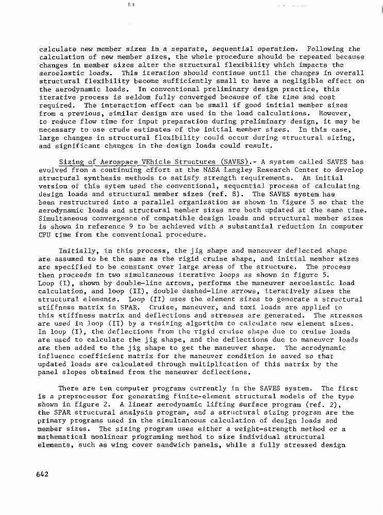
Computation in strength sizing.- Supersonic cruise aircraft tend to have thin, large area wings and are, therefore, very flexible. Strength sizing of such structures poses complex computational problems since the element sizes depend on the stresses caused by the aerodynamic loads that are governed by the structural deformations which, in turn, depend on the element sizes. The problem is further complicated by the necessity to consider inertia dependent loads such as those generated while rolling on a rough runway (taxi loads) and proper consideration of the jig shape (the prescribed aircraft shape at construction which will deform to the desired aerodynamic shape at the cruise condition). The interaction of these physical quantities are indicated in figure 3. A computer-aided synthesis system to size a structure for strength inherently has the same interactions among the computer programs used to calculate these physical quantities.
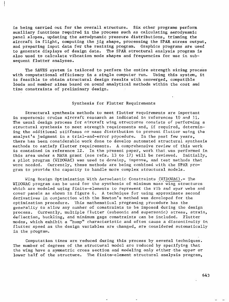
The two principal computational tasks that must be performed during the strength sizing process are (1) the calculation of aeroelastic loads, and (2) sizing of the structural members. These two tasks are illustrated schematically in figure 4. The conventional procedure is first to calculate aeroelastic loads based on initial member sizes and then use these loads to
641
II IllI I
calculate new member sizes in a separate, sequential operation. Following the calculation of new member sizes, the whole procedure should be repeated because changes in member sizes alter the structural flexibility which impacts the aeroelastic loads. This iteration should continue until the changes in overall structural flexibility become sufficiently small to have a negligible effect on the aerodynamic loads. In conventional preliminary design practice, this iterative process is seldom fully converged because of the time and cost required. The interaction effect can be small if good initial member sizes from a previous, similar design are used in the load calculations. However, to reduce flow time for input preparation during preliminary design, it may be necessary to use crude estimates of the initial member sizes. In this case, large changes in structural flexibility could occur during structural sizing, and significant changes in the design loads could result.
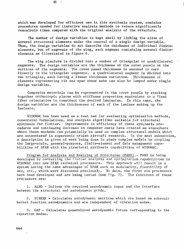
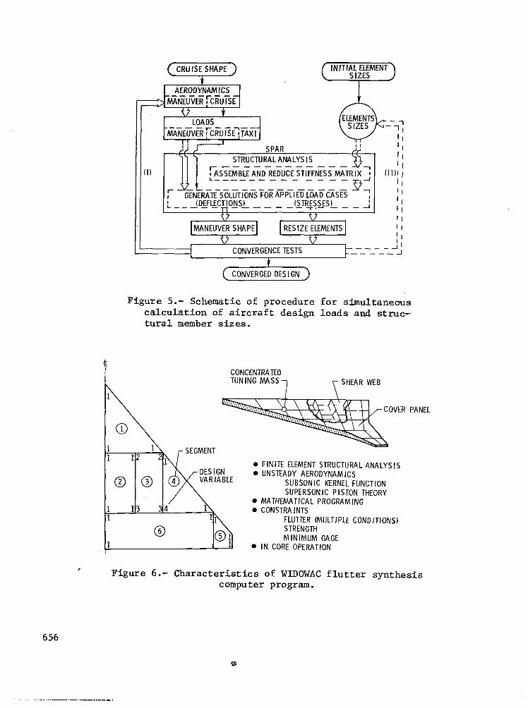
Sizing of Aerospace VEhicle Structures (SAVES).- A system called SAVES has evolved from a continuing effort at the NASA Langley Research Center to develop structural synthesis methods to satisfy strength requirements. An initial version of this sytem used the conventional, sequential process of calculating design loads and structural member sizes (ref. 8). The SAVES system has been restructured into a parallel organization as shown in figure 5 so that the aerodynamic loads and structural member sizes are both updated at the same time. Simultaneous convergence of compatible design loads and structural member sizes is shown in reference 9 to be achieved with a substantial reduction in computer CPU time from the conventional procedure.
Initially, in this process, the jig shape and maneuver deflected shape are assumed to be the same as the rigid cruise shape, and initial member sizes are specified to be constant over large areas of the structure. The process then proceeds in two simultaneous iterative loops as shown in figure 5. Loop (I), shown by double-line arrows, p erforms the maneuver aeroelastic load calculation, and loop (II), double dashed-line arrows, iteratively sizes the structural elements. Loop (II) uses the element sizes to generate a structural stiffness matrix in SPAR. Cruise, maneuver, and taxi loads are applied to this stiffness matrix and deflections and stresses are generated. The stresses are used in loop (II) by a resizing algorithm to calculate new element sizes. In loop (I), the deflections from the rigid cruise shape due to cruise loads are used to calculate the jig shape, and the deflections due to maneuver loads are then added to the jig shape to get the maneuver shape. The aerodynamic influence coefficient matrix for the maneuver condition is saved so that updated loads are calculated through multiplication of this matrix by the panel slopes obtained from the maneuver deflections.
There are ten computer programs currently in the SAVES system. The first is a preprocessor for generating finite-element structural models of the type shown in figure 2. A linear aerodynamic lifting surface program (ref. 2), the SPAR structural analysis program, and a structural sizing program are the primary programs used in the simultaneous calculation of design loads and member sizes. The sizing program uses either a weight-strength method or a mathematical nonlinear programing method to size individual structural elements, 'such as wing cover sandwich panels, while a fully stressed design
642
is being carried out for the overall structure. Six other programs perform auxiliary functions required in the process such as calculating aerodynamic panel slopes, updating the aerodynamic pressure distributions, trimming the aircraft in flight, computing the jig shape, processing the SPAR stress output, and preparing input data for the resizing program. Graphics programs' are used to generate displays of design data. The SPAR structural analysis program is also used to calculate vibration mode shapes and frequencies for use in sub- sequent flutter analyses.
The SAVES system is tailored to perform the entire strength sizing process with computational efficiency in a single computer run. Using this system, it is feasible to obtain structural design results with converged, compatible loads and member sizes based on sound analytical methods within the cost and time constraints of preliminary design.
Synthesis for Flutter Requirements
Structural synthesis methods to meet flutter requirements are important in supersonic cruise aircraft research as indicated in references 10 and 11. The usual design process for aircraft wing structures consists of performing a structural synthesis to meet strength requirements and, if required, determin- ing the additional stiffness or mass distribution to prevent flutter using the analyst's judgment in a trial-and-error procedure. In the past few years, there has been considerable work done to develop automated structural synthesis methods to satisfy flutter requirements. A comprehensive review of this work is contained in reference 12. In the present paper, work that.was performed in this area under a NASA grant (see refs. 13 to 17) will be reviewed. Initially, a pilot program (WIDOWAC) was used to develop, improve, and test methods that were needed. Currently, these methods are being combined with the SPAR pro- gram to provide the capacity to handle more complex structural models.
Wing Design Optimization With Aeroelastic Constraints (WIDOWAC).- The WIDOWAC program can b.e used for the synthesis of minimum mass wing structures which are modeled using finite-elements to represent the rib and spar webs and cover panels as shown in figure 6. A technique for using approximate second derivatives in conjunction with the Newton's method was developed for the optimization procedure. This mathematical programing procedure has the generality to allow any number of constraints to be imposed during the design process. Currently, multiple flutter (subsonic and supersonic) stress, strain, deflection, buckling, and minimum gage constraints can be included. Flutter modes, which exhibit a "hump" characteristic and often cause a discontinuity in flutter speed as the design variables are changed, are considered automatically in the program.
Computation times are reduced during this process by several techniques. The number of degrees of the structural model are reduced by specifying that the wing have a symmetric cross section and modeling only either.the upper or lower half of the structure. The finite-element structural analysis program,
643
IllIll II I I
which was developed for efficient use in this synthesis system, contains procedures needed for iterative-analysis methods to reduce significantly reanalysis times compared with the original analysis of the structure.
The number of design variables is kept small by linking the sizes of several structural elements under the control of a single design variable. Thus, the design variables do not describe the thickness of individual finite- elements, but of segments of the wing, each segment containing several finite- elements as illustrated in figure 6.
The wing planform is divided into a number of triangular or quadrilateral segments. The design variables are the thickness of the cover panels at the vertices of the segments. The cover panel thickness is assumed to vary linearly in the triangular segments. A quadrilateral segment is divided into two triangles, each having a linear thickness variation. Thicknesses of elements representing rib and spar shear webs can also be lumped under single design variables.
Composite materials can be represented in the cover panels by stacking together orthotropic plates with stiffness properties equivalent to a fixed fiber orientation to construct the desired laminates. In this case, the design variables are the thicknesses of each of the laminae making up the laminate.
WIDOWAC has been used as a test bed for evaluating optimization methods, constraint formulations, and analysis algorithms suitable for structural synthesis for.flutter. Improvements in efficiency of these synthesis pro- cedures and continuing decrease in computer costs have created an atmosphere where these methods can potentially be used'on complex structural models which are encountered in supersonic cruise aircraft research. In the next subsection, a description is given of work being done to study complex models by coupling the large-scale, general-purpose, finite-element and data management capa- bilities of SPAR with the structural synthesis capabilities of WIDOWAC.
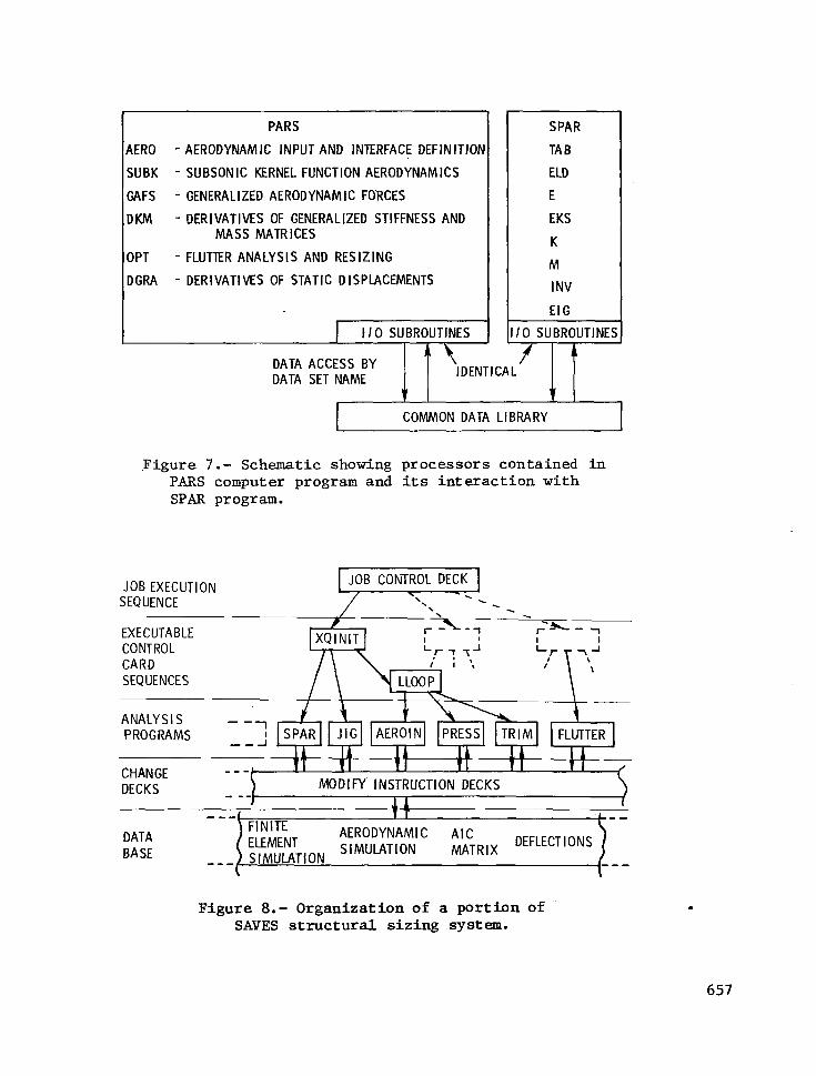
Program for Analysis and Resizing of Structures (PARS).- PARS is being developed by converting the flutter analysis and optimization capabilities in WIDOWAC into new SPAR technical processors. This approach will result in a system having the same advantages of SPAR such as modularity, flexibility of use, etc., which were discussed previously. To date, the first six processors have been developed and are being tested (see fig. 7). The functions of these processors are:
1. ARRO - Defines the required aerodynamic input and the interface between the structural and aerodynamic grids.
2. SUBKRN - Calculates aerodynamic matrices which are based on subsonic kernel function aerodynamics and are independent of vibration modes.
3. GAF - Calculates generalized aerodynamic forces corresponding to the vibration modes.
644
4. DKM- Defines the design variables for use in optimization and calculates the derivatives of the generalized stiffness and mass matrices with respect to these design variables.
5. OPT - Performs a flutter analysis of a specified structure or per- forms a structural optimization to achieve a minimum mass design that satisfies the flutter constraints.
6. DGRA - Calculates the derivatives of displacement vectors with respect to the design variables.
The first five processors provide a flutter analysis capability for sub- sonic Mach numbers. A V-g flutter analysis can be performed at a given alti- tude,or the altitude can be determined at which the flutter velocity and specified Mach number are compatible, or matched, in a given atmosphere. The flutter synthesis option currently in PARS uses the same set of vibration modes all through the resizing process. This requirement limits the application to moderate differences between the initial design and final optimized design. The limitation will be removed by adding capability to make it convenient to return to SPAR to calculate updated vibration modes after significant changes in the structure have occurred and then repeat the optimization in PARS. The last processor, DGRA, calculates the sensitivity of static displacements and stresses to changes in design variables. These quantities are needed to add displacement and stress constraints to the optimization procedure.
The CDC version of PARS is organized in a separate program using the same input/output and data management routines as SPAR and communicating to a common data library as shown in figure 7. This arrangement is desirable during program development because as programing changes are made in the PARS pro- cessors, the entire SPAR system need not be reloaded in the computer. The modularity of the system has expedited the development and testing of PARS and forms the basis for continued developments in structural synthesis.
ORGANIZATION OF STRUCTURAL SYNTHESIS SYSTEMS
Structural synthesis systems are characteristically quite large because of the number of programs and procedures necessary to represent all the disciplines which interact in the sizing process. Thus, the organization of these large systems is an important consideration. Two types of organization represented by SAVES and PARS have been used for the synthesis systems pre- sented herein, with the principal difference being the method used to transfer data among programs and processors. Both of these systems are implemented on the CDC Network Operating System, NOS, and PARS is also implemented on UNIVAC EXEC 8. SAVES makes extensive use of operating system capabilities such as the permanent file system, procedure files, and utilities to change data files which are in the form of card images.
The organization of the SAVES system is indicated on figure 8 which depicts a portion of the total system. The bottom level of the system is a
645
collection of permanent and temporary sequential data files.' Primary or basic input data, including finite-element structural model, aerodynamic paneling data, and load case information, for the system are stored on permanent disk files in the form of card images which are copied to local files during pro- gram execution. Data which are generated by one program and used by another such as deflections, stresses, and aerodynamic pressures are handled as tem- porary local files during a run. These temporary files can be saved and used for restart purposes in a later run.
The next level of the system consists of decks containing file manipula- tion instructions which alter and combine files to form input files for the analysis programs. Some of the analytical programs used for calculating aero- elastic loads in SAVES are shown on the next level. In this organization, the SPAR program must interact with other separate programs and data which are not part of the data library. An example of the data flow which occurs in the series of programs shown in figure 8 will be given to illustrate the method of interfacing the data.
The process is initiated using the cruise shape geometry in the program AEROIN to calculate angles of attack of the aerodynamic panels for use in the subsequent program PRESS which calculates the corresponding pressure distri- bution. The aerodynamic influence coefficients which are generated in PRESS are saved for subsequent calculations. Equilibrated loads for the aircraft in flight are calculated in TRIM based on these pressure distributions. These loads are output in the proper form of input card images for the SPAR program, and "modify instruction" decks are used to merge these data into the finite- element model data. SPAR is then executed to calculate deflections which are stored on the SPAR data library. The SPAR utility, XCOPY, is then used to transfer these deflections to a named sequential file which can be then used by JIG to calculate the jig shape and by AEROIN to calculate a new maneuver shape. The process is then repeated with the data files containing the deflections, jig shape, and maneuver loads being updated during each iteration.
These programs are executed in a prescribed manner by procedure files, which are sequences of executable control cards, as indicated by LLOOP and XQINIT in figure 8. A job control deck, which is the highest level procedure file, is used to control the overall process. Other procedure files indicated by the dotted lines and boxes control other portions of SAVES such as struc- tural sizing, vibration analysis, and subsequent flutter analysis.
A system with the same organization as SAVES can be developed quickly and inexpensively on the basis of standard operating system features as indicated in reference 18. However, as the capabilities of a structural synthesis system are increased, the number of program and data files could become quite large and, hence, difficult to manage and document.
The organization of the PARS system, on the other hand, uses directly the data file management capabilities of the SPAR program as was indicated on figure 7. This bookkeeping system provides a standard form for storing or retrieving data sets by name using direct access files. A limited number of subroutines (user is primarily concerned with two) are used to read or write a
646
data set identified by a four-word name from or into a data library. The size (number of words), along with other descriptive information for the data sets, are contained in tables of contents embedded in the data libraries. Documen- tation involves only specifying the physical meaning of the contents of each data set and specifying which of these data sets are input to or output from each of the processors.
The capability for performing.loops within a single input deck is cur--. rently not available in SPAR or PARS. Procedure files such as used in SAVES can be used to accomplish this needed function with the common data libraries being retained between multiple executions of SPAR or PARS. This organization provides a flexible framework on which to add improved or extended structural synthesis methods.
FUTURE DEVELOPMENTS
On-going and planned improvements to the structural synthesis systems include continued work on incorporating methods to size structural components made of composite materials. This work will augment development of methods for synthesis of structures to meet overall stiffness constraints, as well as strength constraints. Testing of the flutter synthesis. methods on large, complex structural models will be continued along with development of any needed improvements in these methods that-may become apparent in a large problem environment.
Improved calculation of the required aerodynamic quantities for these synthesis systems will be obtained by incorporating the capabilities of the SOUSSA (Steady, Oscillatory, Unsteady Subsonic and Supersonic Aerodynamics) program of reference 19. This program will augment or replace the steady lifting surface aerodynamics and unsteady subsonic kernel function aerodynamics cur- rently being used. SOUSSA will provide the capability to handle complex three- dimensional configurations'with a single, common aerodynamic paneling arrange- ment for both subsonic and supersonic flight regimes. Some alterations of the program will probably be required for efficient operation in an iterative structural synthesis environment. This improved aerodynamic capability will then be organized and implemented in the form of processors for use in the PARS system to take advantage of the SPAR data handling and utility functions.
The capability to assess the effects of including active control systems is becoming an important consideration in the development of structural anal- ysis and synthesis systems. This capability will be initially introduced into the PARS system by including the effect of active controls in the flutter analysis. Additional processors associated with formulating the flutter analysis in the proper form will be required for this work.
As new procedures and new processors are developed for SAVES, SPAR, and PARS, they will provide a basic framework and flexibility of use to test and develop other structural synthesis methods and strategies. Therefore, the
647
I llllllll I I
consideration of modularity, efficiency, and ease of use and modifications must be planned and incorporated into the system so new development can concentrate on what is new technically and not have to rebuild or restructure existing programs or processors.
CONCLUDING REMARKS
Computer-aided design methods have been developed by incorporating sound theoretical procedures from a variety of disciplines into systems which have the capacity to handle the detailed simulations required for the analysis and synthesis of supersonic cruise aircraft structures. Finite-element structural analysis methods are available to analyze the linear behavior of a given structure efficiently and in great detail. Structural synthesis methods for sizing structures to meet strength requirements have been developed based on a fully stressed criterion. Compatible member sizes and aircraft design loads can be calculated using a simultaneous iteration procedure during this structural sizing process. Synthesis methods to size the members of large-scale structural simulations to meet flutter requirements have been developed by incorporating efficient analysis and reanalysis methods, approximation techniques, and design variable linking with mathematical programing procedures. The development of these systems has improved the design process by allowing more interacting disciplines to be considered in greater depth and with a decrease in overall flow time.
Flexibility, efficiency, and ease of modification of these systems are important for use in advanced design applications such as supersonic cruise aircraft research because new demands are continually being made on these systems. These requirements have brought into focus the desirability of modular systems which make effective use of capabilities available on time- share operating systems. Needed technical capabilities are being developed for incorporation into these design systems. These capabilities include improved structural resizing methods (especially for stiffness considerations) and improved aerodynamics, as well as capability to consider composite materials and active controls in the structural design.
648
REFERENCES
1. Butler, Thomas G.; and Michel, Douglas: A Summary of the Functions and Capabilities of the NASA Structural Analysis Computer System. NASA SP-260, 1971.
2. Carmichael, Ralph L.; and Woodward, Frank A.: An Integrated Approach to the Analysis and Design of Wings and Wing-Body Combinations in Supersonic Flow. NASA TN D-3685, 1966.
2. Watkins, Charles E.; Woolston, Donald S.; and Cunningham, Herbert J.: A Systematic Kernel Function Procedure for Determining Aerodynamic Forces on Oscillating or Steady Finite Wings at Supersonic Speeds. NASA TR R-48, 1959.
4. Donato, V. W.; and Huhn, C. R., Jr.: Supersonic Unsteady Aerodynamics for Wings With Trailing Edge Control Surfaces and Folded Tips. AFFDL TR-68-30, U.S. Air Force, August 1968.
5. Whetstone, W. D.: Computer Analysis of Large Linear Frames. Journal of the Structural Division, ASCE, November 1969, pp. 2401-2417.
6. Whetstone, W. D.: Vibrational Characteristics of Linear Space Frames. Journal of the Structural Division, ASCE, October 1969, pp. 2077-2091.
7. Sobieszczanski, J.: Structural Design Studies of a Supersonic Cruise Arrow-Wing Configuration. Supersonic Cruise Aircraft Research (SCAR) Conference, Hampton, Virginia, November 9-12, 1976.
8. Giles, G. L.; Blackburn, C. L.; and Dixon, S. C.: Automated Procedures for Sizing Aerospace Vehicle Structures (SAVES). Journal of Aircraft, Vol. 9, No. 12, December 1972, pp. 812-819.
9. Giles, G. L.; and McCullers, L. A.: Simultaneous Calculation of Aircraft Design Loads and Structural Member Sizes. AIAA Paper No. 75-965, August 1975.
10. Sakata, I. F.; Davis, G. W.; Robinson, J. C.; and Yates, E. C., Jr.: Design Study of Structural Concepts for an Arrow-Wing Configuration Supersonic Cruise Aircraft. AIAA Paper No. 75-1037, August 1975.
11. Robinson, J. C.; Yates, E. C., Jr.; Turner, J. M.; and Grande, D. L.: Application of an Advanced Computerized Structural Design System to an Arrow-Wing Supersonic Cruise Aircraft. AIAA Paper No. 75-1038, August 1975.
12. Stroud, W. J.: Automated Structural Design With Aeroelastic Constraints: A Review and Assessment of the State of the Art. In AMI), Vol. 7, pub- lished by ASME, 1974.
649
I lllll IllIll
13. Haftka, Raphael T.: Automated Procedure for Design of Wing Structures to Satisfy Strength and Flutter Requirements. NASA TN D-7264, 1973.
14. Haftka, R. T.; and Starnes, J. H., Jr.: WIDOWAC (Wing Design Optimization With Aeroelastic Constraints): Program Manual. NASA TM X-3071, October 1974.
15. Haftka, R. T.: Parametric Constraints With Application to Optimization for Flutter Using a Continuous Flutter Constraint. AIAA Journal, Vol. 13, No. 4, April 1975, pp. 471-475.
16. Haftka, R. T.; and Starnes, J. H., Jr.: Applicatons of a Quadratic Extended Interior Penalty Function for Structual Optimization. AIAA Paper No. 75-764, May 1975.
17. Haftka, R. T.; and Yates, E. C., Jr.: On Repetitive Flutter Calculations in Structural Design. AIAA Paper No. 74-141, January 1974.
18. Sobieszczanski, J.: Building a Computer-Aided Design Capability Using a Standard Time Share Operating System. Presented at the ASME Winter Annual Meeting, Houston, Texas, December 1975, and published in the ASME special publication "Integrated Design and Analysis of Aerospace Structures."
19. Yates, E. C., Jr.; and Bland, S. R.: Developments in Steady and Unsteady Aerodynamics for Aeroelastic Analysis and Design. Supersonic Cruise Aircraft Research (SCAR) Conference, Hampton, Virginia, November 9-12, 1976.
650
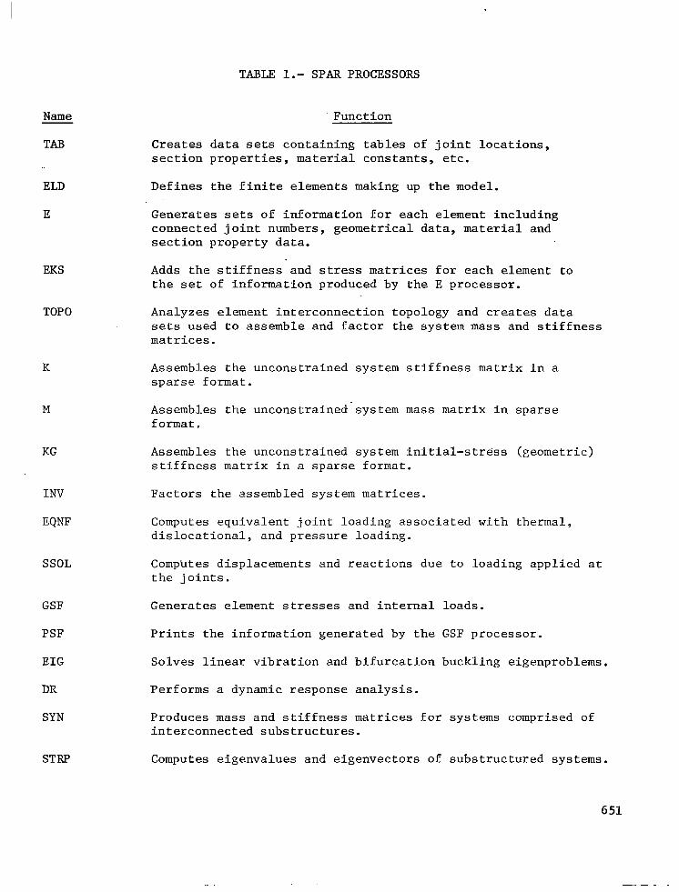
TABLE l.- SPAR PROCESSORS
Function Name
TAB
ELD
E
EKS
TOP0
K
M
KG
INV
EQNF
SSOL
GSF
PSF
EIG
DR
SYN
STRP
Creates data sets containing tables of joint locations, section properties, material constants, etc.'
Defines the finite elements making up the model.
Generates sets of information for each element including connected joint numbers, geometrical data, material and section property data.
Adds the stiffness and stress matrices for each element to the set of information produced by the E processor.
Analyzes element interconnection topology and creates data sets used to assemble and factor the system mass and stiffness matrices.
Assembles the unconstrained system stiffness matrix in a sparse format.
Assembles the unconstrained'system mass matrix in sparse format.
Assembles the unconstrained system initial-stress (geometric) stiffness matrix in a sparse format.
Factors the assembled system matrices.
Computes equivalent joint loading associated with thermal, dislocational, and pressure loading.
Computes displacements and reactions due to loading applied at the joints.
Generates element stresses and internal loads.
Prints the information generated by the GSF processor.
Solves linear vibration and bifurcation buckling eigenproblems.
Performs a dynamic response analysis.
Produces mass and stiffness matrices for systems comprised of interconnected substructures.
Computes eigenvalues and eigenvectors of substructured systems.
651

Name
AUS
DCU
VPRT
PLTA
PLTB
Ill III I I
TABLE l.- SPAR PROCESSORS (Concluded)
Function
Performs an array of matrix arithmetic functions and is used in construction, editing, and modification of data sets.
Performs an array of data management functions including display of table of contents, data transfer between libraries, changing data set names, printing data sets, and transferring data between libraries and sequential files.
Performs editing and printing of data sets which are in the form of vectors on the data libraries.
Produces data sets containing plot specifications.
Generates the graphical displays which are specified by the PLTA processor.
652
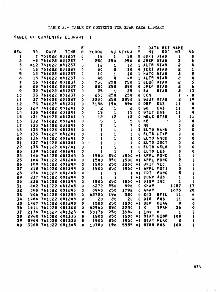
TABLE 2.- TABLE OF CONTENTS FOR SPAR DATA LIBRARY
TABLE OF CONTENTS, LIBRARY 1
SEQ 1
:
z 6 7 0 9
10 11 12
:t 15 16 17 10 19 20
2 23 24 25
1: 20 29 30
3: 33
3; 36 37 38 19
RR 7
aa -12
13 14 15
:8 32 33
K 129 130 151 132 133 134 135 136 137 138
'139 140 164 188 212 236 a37 230 262 360 506
1466 1487 1511 2176 2960 2984
DATE TIME 761022 081237 761022' 081237 761022 081237 761022 081237 761022 081237 761022 081237 761022 081237 761022 081237 761022 081237 761022 081237 761022 081237 761022 081241 761022 081241 7blo22 081241 761022 081241 761022 081241 761022 081241 761022 081241 761022 081241 761022 otriavi 761022 081241 761022 081241 761022 081241 761022 081244 761022 081244 761022 081244 761022 081244 761022 081244 761022 081244 761022 oeia44 761022 081245 761022 081245 761022 0111254 761022 081248 761022 081248 761022 081302 7bLO2? 081323 761022 081333 761022 081333
40 3008 761022 08;345
E R 0 0 0
x 0
i 0 0 0 0 0 0 0 (r 0 0 0 0 0 0 0 a 0 0 0 0 0 0 0 0 0 0 0 0 0 0 0 0
WORDS
2::
:;: 10
7:: 2so
2:: 2250 3136
2 15 12
5 7 1
:
:
15Oii lSO0 l500 is00
1
150: 6272 8960
62720 20
1500 42560 50176
1500 1500
NJ NI*NJ 1
250 2:: 1 12 2 30 1 10
25: 750 46
250 250 as; 250 25
250 2250 196. 896
: 15 a
12 12 1 5
: 7 1 1 1
: :
: 1 1 2'30. 1500 a50 1500 250 1500 250 1500
1 1
25: 1SOii 250 896 250 1792 196 320
20 20 250 1500 250 2240 250 3584 290 1500 a50 1500
DATA 3Et i Nl N2 0 JDPi BTAB 0 JREf BTAB 1 ALfFi BTAEI 4 TEXt BTAB 1 MATC BTAB 1 ALTR BTAB 1 JLOC BTAB 0 JREF BTAB 1 BA BTA0 0 CON 1 QJJT BTAB 0 DEF E43 0 GO E43 0 GTlT E43 0 NeLt cJTAB 0 KE ONS 3 ELTS NAME 0 ELTB LTYP 0 ELT6 NNOD 0 ELTS ISCT 0 CL18 NE&ii 0 ELT* LE3
-1 APPL FORC 11 APPL FORC -1 UNIT VEC -1 APPL HOTI -1 TOT fORC -1 CONV AUS -1 OISP INC
0 KMAf' 0 AMAP 4 E43 EfIL 0 OIR E43
-1 DEM DlAG 1 K 8PAlf 1 INV iC
-1 STAT Df8P -1 STAT REAC
NAME N3
1
f
f
: 2 2
: 11 11 11 .l 0
8 0 0 0 0 0
:
: 5 !
108: lb75
::
3:
10: 2
10780 196 5555 11 STRj E43 100
NY 8
::
:
i
1:
1: 4 4 4
11 0
FJ
8 0
Fl 1
: 1 1
:
:x 4 4 0 0 0
: 1
653
IllI II lllll IIIII I I I
INPUT FILE
TECHNICAL PROCESSORS i UTILITY PROCESSORS
TAB TOP0 EQNF EIG I !
AUS
ELD K SSOL DR I DCU
E M GSF I
SYN I VPRT I
EKS KG PSF STRP I PLTA
INV I I I PLTB
DATA BASE COMPLEX
:,:6: pitj..Ti
FILE = SPARLA = SPARLB = SPARLT
Figure l.- Organization of SPAR computer program.
CONSTRUCTION 1
746 GRID POINTS
2369 ELEMENTS (TOTAL) 718 SIZED ELEMENTS
Figure 2.- Finite-element simulation of a supersonic cruise aircraft configuration.
654
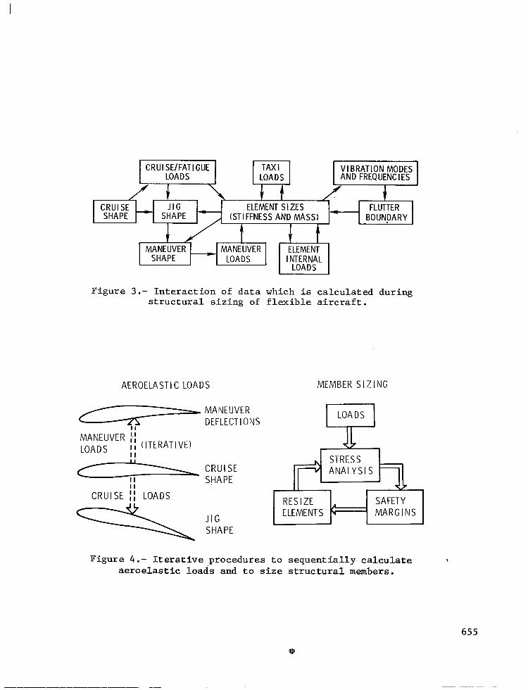
Figure 3.- Interaction of data which is calculated during structural sizing of flexible aircraft.
AEROELASTIC LOADS MEMBER SIZING
ii MANEUVER i, ,, (ITERATIVE) LOADS ,, I I
\ CRUISE II II SHAPE
CRUISE I) LOADS RESIZE ELEMENTS c
SAFETY ' MARGINS
Figure 4.- Iterative procedures to sequentially calculate aeroelastic loads and to size structural members.
655
II I (DEFLECTIONS) (STRESSES) , L----- --------T,- ----I
’ I ’ I
tf t* I .
II IMANEUV;; SHAPE] j ; 1 RESIZE;~NTS 1
I ’ I CONVERGENCE TESTS t---------5
( CONVERGED DESIGN )
Figure 5.- Schematic of procedure calculation of aircraft design tural member sizes.
CONCENTRATED TUNING MASS 7
for simultaneous loads and struc-
\ SHEAR WEB
,- SEGMENT - - / 1 13 4 1 ti?h 1 11
@ 01 1 1
l FINITE ELEMENT STRUCTURAL ANALYSIS . UNSTEADY AERODYNAMICS
SUBSONIC KERNEL FUNCTION SUPERSONIC PISTON THEORY
. MATHEMATICAL PROGRAMING
. CONSTRAINTS FLUTIER (MULTIPLE CONDITIONS) STRENGTH M IN IMUM GAGE
l IN CORE OPERATION
PANEL
, Figure 6.- Characteristics of WIDOWAC flutter synthesis computer program.
656
PARS
9ERO - AERODYNAMIC INPUT AND INTERFACE DEFIN ITIOI
SUBK - SUBSONIC KERNEL FUNCTION AERODYNAMICS
GAFS - GENERALIZED AERODYNAMIC FORCES
DKM - DERIVATIVES OF GENERALIZED STIFFNESS AND MASS MATRICES
OPT - FLUTTER ANALYSIS AND RESIZING
DGRA - DERIVATIVES OF STATIC DISPLACEMENTS
] I10 SUBROUTINES
SPAR
TAB ELD E
EKS
K M INV
EIG I IO SUBROUTINE’
DATA ACCESS BY A t
DATA SET NAME IDENTICAL h ‘T
COMMON DATA LIBRARY
Figure 7.- Schematic showing processors contained in PARS computer program and its interaction with SPAR program.
JOB EXECUTION SEQUENCE
EXECUTABLE CONTROL CARD SEQUENCES
CHANGE ---
Figure 8.- Organization of a portion of SAYES structural sizing system.