Embed Size (px)
Citation preview
Proceedings of the 2016 International Conference on Industrial Engineering and Operations Management Detroit, Michigan, USA, September 23-25, 2016
Computer Aided Process Planning Approach for Cost Reduction and Increase in Throughput
Omar Al-Shebeeb Department of Industrial and Management Systems Engineering
West Virginia University Morgantown, WV 26506, USA
Bhaskaran Gopalakrishnan Department of Industrial and Management Systems Engineering
West Virginia University Morgantown, WV 26506, USA
Abstract
The use of effective software in Computer Aided Process Planning (CAPP) can contribute significantly towards cost reduction and improvement in production rate. The most important elements of CAPP are the ability to effectively evaluate various machining process sequences and the utilization of the most appropriate machining parameters including machines, tools and tool grades and tool angles, cutting fluids, cutting conditions, cutting speed, and feeds. The evaluation can be done effectively utilizing MPSEL and VISUAL MACH, software that are based on expert systems and cost computing algorithms. MPSEL is an expert system based software tool that inferences based on backward chaining rules. VISUAL MACH is spreadsheet based software that accurately estimates production cost and production rate based on specific machining operational parameters and product design attributes. For the case studies illustrating the use of the software, a specific manufacturing process based infrastructure will be assumed with a repository of specific case studies will be discussed illustrating the use of the software to enable significant cost reductions and production rate increases for product designs. The sensitivity of production cost and production rate with respect to varying product, process, and system level parameters will be explored and conclusions derived. The results showed that process plan one has the main effect on cost reduction and increasing production rate (with cost saving 47.413%). Then, the process plan three has the second rank (with cost saving 38.834%). And finally the process plan two (with cost saving 30.26%)
Keywords Machining, design, cost, production rate
1. IntroductionModern manufacturing companies focus on automation of manufacturing systems, especially on the automation ofprocess planning and production planning and control functions. Because of global competition, manufacturingdecisions have to be made within a short time frame with desirable outcomes. Obtaining the proper information andknowledge are important to reach the right decisions about selecting the most desirable manufacturing process and itsparameters. The process planning function can assist in selecting the right processes and their sequences. Processplanning can be defined as steps and instructions to convert design information into manufacturing process orientedinformation. The management is always interested in reducing the machine idle running time and machine waitingtime and that can be facilitated by proper application of process planning. For instance, after applying the processplanning function, it will lead to use the machine with lowest idle time and lowest waiting time, as an example usingthe CNC lathe to do the turning process instead of using a turret lathe machine. Process planning gives the process
© IEOM Society International 632
Proceedings of the 2016 International Conference on Industrial Engineering and Operations Management Detroit, Michigan, USA, September 23-25, 2016
planner the information about machines and tools appropriate to a process in accordance with the mechanical properties of the raw material and the design of the product. The current study focused on integrating the process planning and machining parameter selection to produce a part with lower cost and higher production rate. The Computer Aided Process Planning (CAPP) function, on account of the utilization of algorithms, expert systems and databases, can play a significant role in generative and variant systems development with required accuracy.
1.2 Research Objectives The main objective of this research is to evaluate machining processes by analyzing process plans and inherent process parameters. This evaluation has been done by using CAPP software to compare different process plans in term of machining cost, and tooling cost. The work done should provide the process planner with much needed information about the manufacturing cost attributable to the process plans.
The research objectives are as follows: 1. To select machining parameters and to develop different process plans using MPSEL software.2. To calculate the machining cost and tooling cost for the process plans using VISUAL MACH excel
spreadsheet program.3. To analyze and compare the differences to machining cost by changing raw material, design of process,
design of part, and quality of the part.4. To compare and evaluate the process planning based on total machining process cost (Machining cost and
tool cost) by using three Computer Aided Process planning (CAPP) programs.
2. Literature review
2.1 Computer Aided Process Planning The manufacturing process is the centerpiece of any process plan, along with the inherent instructions and guidance to attain the finished product. Process planning is the intermediate stage between design and manufacturing. In manufacturing companies, the main concern of the management is how to manufacture a product with low cost and high quality, so as to be competitive. Process plans are directly related to many factors such as production rate, cost, operations, tools, machines, surface finish, and quality. When process plans were developed manually, the chance of errors increased and manufacturing process decisions were often less desirable. The automated CAPP functionality assists in this regard. Process sequence design and construct plays the main role in (CAPP, for forming process like non-axisymmetric deep drawing product with elliptical shape (Kang & Park, 2002). Other studies presented a genetic algorithm (GA) to reduce processing time on single and distributed manufacturing system. By applying the GA to CAPP system, optimal or near-optimal process planning based on specific criterion have been chosen (Li, Fuh, Zhang, & Nee, 2005). General overview has been done in a field of sheet metal forming by applying two approaches. First one by using CAPP and the other one by using simulation based process planning. As a result, special results have been introduced in this development study (Tisza, 2007). Another researcher proposed a methodology by applying CAPP on extract rotational parts by using 2D data file as input by dividing this methodology into three different procedures and presenting two sample application descriptions (Kabir, Md Deloyer Jahan Golam, 2010). Three technologies, CAPP, Computer Aided Design (CAD), and Computer Aided Manufacturing (CAM) have been integrated to review the development of process planning for manufacturing of the mold for injection molding (Tepi, Todi, Luki, Milo, & Borojevi, 2011). To determine the capabilities of genetic algorithms in term of process planning in manufacturing and to redesign manufacturing processes, two genetic algorithms have been proposed and employed to obtain the best approach about the solution for process planning (Ismail, Musharavati, Hamouda, & Ramli, 2008). Comprehensive survey on CAPP has been done for fourteen years from 2002 to 2013 based on artificial neural networks, genetic algorithms (GA), fuzzy set theory and fuzzy logic, Petri nets (PN), Agent, Internet, and other algorithms and methods. Up-to-date information with graphical representation of CAPP have been provided to understand the past, present, and future of CAPP (Yusof & Latif, 2014).
2.2 Process Planning in Manufacturing and Machining In terms of using process planning in manufacturing, intelligent agents have been used for connecting the preliminary design with manufacturing planning software systems. For supporting this integration a prototype agent platform has been created. Process planner can obtain the information about selecting the manufacturing processes, determining manufacturing strategies, and providing information to the designer through the process planning agents. The benefits of such process planning efforts are to support product preliminary design, optimize production systems, and reduce
© IEOM Society International 633
Proceedings of the 2016 International Conference on Industrial Engineering and Operations Management Detroit, Michigan, USA, September 23-25, 2016
the manufacturing cost in the preliminary design stages (Feng & Song, 2002). Monte Carlo simulation has been used to select the most appropriate manufacturing processes for servo valve component manufacture. Simulation has been used to evaluate the effect of servo valve design parameters on the system using statistical techniques. As a result, for estimating the reliability of the system, manufacturing processes have been analyzed and the justification for the use of each process has been explained (Samadani, Behbahani, & Nataraj, 2013). Sustainable process planning efforts lead to a reduction of resource demands, especially in producing high precision components (Goldhahn & Eckardt, 2016). Cloud and internet based information related to manufacturing has been used for development of process planning parameters (L. Wang, 2013). A study has been done to integrate the tool path generation and feed selection to minimize machining time under cutting force constraints. This work proposes a process planning for machining of the most prominent machining feature in a 2½D pocket. The tool path generation and feed selection have been proposed to be integrated with an objective of minimizing machining time under realistic cutting force constraints for a given pocket geometry and cutting tool. The comparison has been made between the proposed tool path strategy and paths generated by using Computer Aided Manufacturing (CAM) software. Then the result showed that 32% to 40% improvement in productivity can be achieved by using this proposed integration between tool path generation and process planning (Banerjee, Feng, & Bordatchev, 2012). To exploit the unique characteristics of additive manufacturing (AM) and to determine processing limits, two levels of evaluation framework have been presented to evaluate the design by process planning. Efforts to improve the design by utilizing the information from process planning has been examined (Y. Zhang, Bernard, Gupta, & Harik, 2014). For integrate effective scheduling and process planning, a model has been developed by using an integrated definition (IDEF) methodology. This methodology was used to combine the process oriented decisions with production planning in metal removal processes (machining) in term of activities (Ciurana, Garcia-Romeu, Ferrer, & Casadesús, 2008). Studies have been applied to improve tool selection for arbitrary shaped pockets by applying polygon subdivision techniques. The tool in machining processes have been selected based on machining time and tool life. Implementing this approach has reduced machining time compared to previous research efforts in this domain (Makhe & Frank, 2010) (14). For shortening the gap between computer systems and CNC systems for adaptive machining, a new adaptive process planning method has been developed, which has the ability to generate process plans with adaptation to unplanned changes (L. Wang, 2015). Another contribution of the researchers was to minimize energy consumption by scheduling the process planning in the manufacturing industry to improve the energy saving of machining system. This approach has been based on a nonlinear process planning (NLPP) model which has been used to predict energy consumption. The genetic algorithmic approach has been used through NLPP, and alternative scheduled process plans have been generated with lower energy consumption by machining processes (Z. Zhang, Tang, Peng, Tao, & Jia, 2016). Another approach was to improve the implementation of sustainability in manufacturing systems with characteristics of high variety and low volume by developing an approach for scheduling optimization in milling process planning (S. Wang, Lu, Li, & Li, 2015).
3. Software and Tools Used to Calculate Total Machining Costing
3.1 MPSEL MPSEL is an acronym for Machining Parameter Selection System developed at West Virginia University. It is an expert system developed to select different machining parameters like machine tools, cutting tools, cutting fluids and to indicate the different cutting conditions. The different cutting conditions include, thermal shock, high tool chip friction etc. The expert system considers the following machine shop environment in which engine lathe, NC lathe, turret lathe, single spindle automat, cylindrical grinding machine, surface grinding machine, horizontal milling machine, vertical milling machine, NC mill, Turret drilling machine, vertical drilling machine and radial drilling machine are available. The processes that are considered in this system are, turning, facing, milling, grinding, drilling, reaming, boring, tapping and threading. Selection of machines and cutting tools is a time consuming process as it involves many parameters and is subject to operational constraints such as machine capacity, tool work combination, and surface finish requirement. MPSEL is designed to select the appropriate machines and cutting tools for a machining process based on the design of the part. This is done by consulting with the expert system, which has expert knowledge, built in about the processes. This minimizes the time and effort required for the selection of cutting tools, cutting fluids and machine tools.
3.2 VISUAL MACH
© IEOM Society International 634
Proceedings of the 2016 International Conference on Industrial Engineering and Operations Management Detroit, Michigan, USA, September 23-25, 2016
VISUAL MACH is a spreadsheet application that can be used for calculating the machining cost and tool cost for a particular machining operation. The total cost of machining is calculated for each cutting pass and they are integrated to arrive at the total cost to produce a single part using the selected machining process parameters. Machine setup time cost, work loading, unloading, and tool changing cost are also included in the machining cost. The spreadsheet includes calculation of cost for turning, face or end milling, drilling, surface grinding, reaming and tapping. The cost of each machining process per pass is obtained by using the formula discussed in the following chapter. It also gives detailed information about the machining time components, tool cost components and the machining cost components. These details are more useful in the analysis of the selected machining parameters in terms of machining cost. Similar to MPSEL, the MACH spread sheet program was also run for each and every process for calculating the machining time, machining cost and tooling cost. In each process, it was run for every cutting passes. The cutting parameters used were selected from industry recommended values for depth of cut, feed rate and cutting speed. The constraints of machines such as machine capacity, tooling capacity and tool life were also considered in coming up with the cutting parameters.
4. Economics of machiningThe economics of machining is based upon two types of constraints based on one criterion. They are as follows (AMCShop floor practice, 1992):
1. Minimum machining cost2. Maximum production rate
The total cost of machining is obtained by the sum of a series of costs and these cost sections can be divided into two groups:
1. Machine cost2. Tool reconditioning cost
The individual time elements, which are involved in finding the total machining time, which is, further, used in machine cost are as follows:
1. Feed time2. Rapid traverse time3. Load and unload time4. Setup time5. Tool change time
The elements that are considered in finding the tool reconditioning costs are as follows: 1. Tool depreciation cost2. Tool resharpening cost3. Rebrazing or blade reset cost4. Insert or blade cost5. Grinding wheel cost
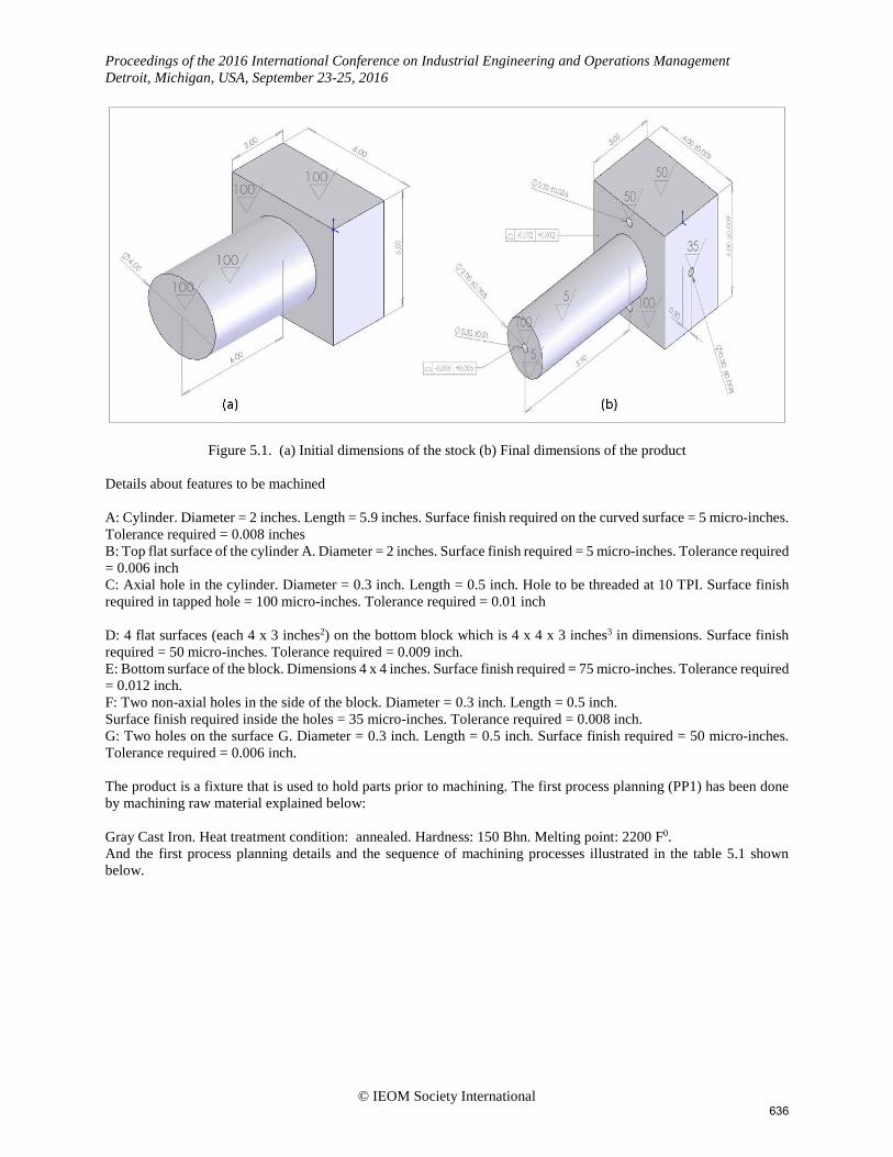
5. Case study of process planningThis section focuses on the utilization of MPSEL and VISUAL MACH to determine process planning attributes.Figure 5.1 (a) shows the initial stock dimensions of the part has to be machined by using process planning and figure5.1 (b) explains the final dimensions of the part after applying process planning by using machining processes. Thepart is a fixture used to drill axial holes in hollow cylinders with significant lengths. The details for the stock andproduced part are illustrated below:
© IEOM Society International 635
Proceedings of the 2016 International Conference on Industrial Engineering and Operations Management Detroit, Michigan, USA, September 23-25, 2016
Figure 5.1. (a) Initial dimensions of the stock (b) Final dimensions of the product Details about features to be machined A: Cylinder. Diameter = 2 inches. Length = 5.9 inches. Surface finish required on the curved surface = 5 micro-inches. Tolerance required = 0.008 inches B: Top flat surface of the cylinder A. Diameter = 2 inches. Surface finish required = 5 micro-inches. Tolerance required = 0.006 inch C: Axial hole in the cylinder. Diameter = 0.3 inch. Length = 0.5 inch. Hole to be threaded at 10 TPI. Surface finish required in tapped hole = 100 micro-inches. Tolerance required = 0.01 inch D: 4 flat surfaces (each 4 x 3 inches2) on the bottom block which is 4 x 4 x 3 inches3 in dimensions. Surface finish required = 50 micro-inches. Tolerance required = 0.009 inch. E: Bottom surface of the block. Dimensions 4 x 4 inches. Surface finish required = 75 micro-inches. Tolerance required = 0.012 inch. F: Two non-axial holes in the side of the block. Diameter = 0.3 inch. Length = 0.5 inch. Surface finish required inside the holes = 35 micro-inches. Tolerance required = 0.008 inch. G: Two holes on the surface G. Diameter = 0.3 inch. Length = 0.5 inch. Surface finish required = 50 micro-inches. Tolerance required = 0.006 inch. The product is a fixture that is used to hold parts prior to machining. The first process planning (PP1) has been done by machining raw material explained below: Gray Cast Iron. Heat treatment condition: annealed. Hardness: 150 Bhn. Melting point: 2200 F0. And the first process planning details and the sequence of machining processes illustrated in the table 5.1 shown below.
© IEOM Society International 636
Proceedings of the 2016 International Conference on Industrial Engineering and Operations Management Detroit, Michigan, USA, September 23-25, 2016
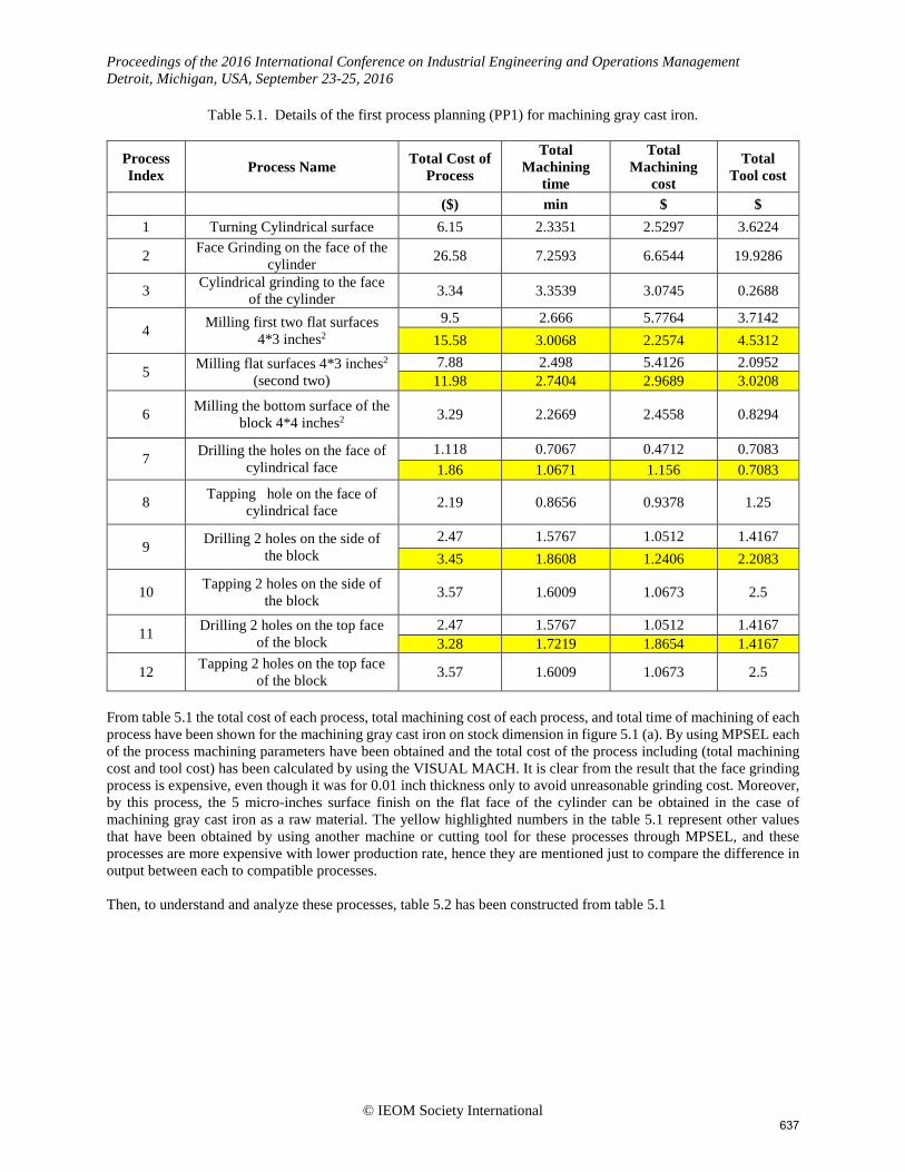
Table 5.1. Details of the first process planning (PP1) for machining gray cast iron.
Process Index Process Name Total Cost of
Process
Total Machining
time
Total Machining
cost
Total Tool cost
($) min $ $ 1 Turning Cylindrical surface 6.15 2.3351 2.5297 3.6224
2 Face Grinding on the face of the cylinder 26.58 7.2593 6.6544 19.9286
3 Cylindrical grinding to the face of the cylinder 3.34 3.3539 3.0745 0.2688
4 Milling first two flat surfaces 4*3 inches2
9.5 2.666 5.7764 3.7142 15.58 3.0068 2.2574 4.5312
5 Milling flat surfaces 4*3 inches2 (second two)
7.88 2.498 5.4126 2.0952 11.98 2.7404 2.9689 3.0208
6 Milling the bottom surface of the block 4*4 inches2 3.29 2.2669 2.4558 0.8294
7 Drilling the holes on the face of cylindrical face
1.118 0.7067 0.4712 0.7083 1.86 1.0671 1.156 0.7083
8 Tapping hole on the face of cylindrical face 2.19 0.8656 0.9378 1.25
9 Drilling 2 holes on the side of the block
2.47 1.5767 1.0512 1.4167 3.45 1.8608 1.2406 2.2083
10 Tapping 2 holes on the side of the block 3.57 1.6009 1.0673 2.5
11 Drilling 2 holes on the top face of the block
2.47 1.5767 1.0512 1.4167 3.28 1.7219 1.8654 1.4167
12 Tapping 2 holes on the top face of the block 3.57 1.6009 1.0673 2.5
From table 5.1 the total cost of each process, total machining cost of each process, and total time of machining of each process have been shown for the machining gray cast iron on stock dimension in figure 5.1 (a). By using MPSEL each of the process machining parameters have been obtained and the total cost of the process including (total machining cost and tool cost) has been calculated by using the VISUAL MACH. It is clear from the result that the face grinding process is expensive, even though it was for 0.01 inch thickness only to avoid unreasonable grinding cost. Moreover, by this process, the 5 micro-inches surface finish on the flat face of the cylinder can be obtained in the case of machining gray cast iron as a raw material. The yellow highlighted numbers in the table 5.1 represent other values that have been obtained by using another machine or cutting tool for these processes through MPSEL, and these processes are more expensive with lower production rate, hence they are mentioned just to compare the difference in output between each to compatible processes. Then, to understand and analyze these processes, table 5.2 has been constructed from table 5.1
© IEOM Society International 637
Proceedings of the 2016 International Conference on Industrial Engineering and Operations Management Detroit, Michigan, USA, September 23-25, 2016
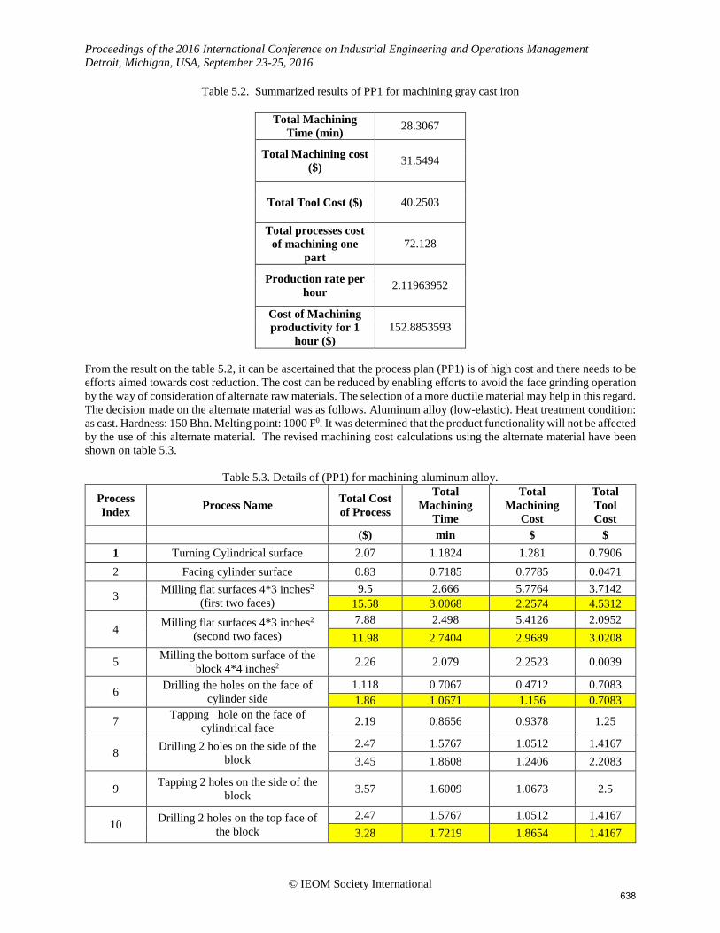
Table 5.2. Summarized results of PP1 for machining gray cast iron
Total Machining Time (min) 28.3067
Total Machining cost ($) 31.5494
Total Tool Cost ($) 40.2503
Total processes cost of machining one
part 72.128
Production rate per hour 2.11963952
Cost of Machining productivity for 1
hour ($) 152.8853593
From the result on the table 5.2, it can be ascertained that the process plan (PP1) is of high cost and there needs to be efforts aimed towards cost reduction. The cost can be reduced by enabling efforts to avoid the face grinding operation by the way of consideration of alternate raw materials. The selection of a more ductile material may help in this regard. The decision made on the alternate material was as follows. Aluminum alloy (low-elastic). Heat treatment condition: as cast. Hardness: 150 Bhn. Melting point: 1000 F0. It was determined that the product functionality will not be affected by the use of this alternate material. The revised machining cost calculations using the alternate material have been shown on table 5.3.
Table 5.3. Details of (PP1) for machining aluminum alloy.
Process Index Process Name Total Cost
of Process
Total Machining
Time
Total Machining
Cost
Total Tool Cost
($) min $ $ 1 Turning Cylindrical surface 2.07 1.1824 1.281 0.7906 2 Facing cylinder surface 0.83 0.7185 0.7785 0.0471
3 Milling flat surfaces 4*3 inches2 (first two faces)
9.5 2.666 5.7764 3.7142 15.58 3.0068 2.2574 4.5312
4 Milling flat surfaces 4*3 inches2 (second two faces)
7.88 2.498 5.4126 2.0952 11.98 2.7404 2.9689 3.0208
5 Milling the bottom surface of the block 4*4 inches2 2.26 2.079 2.2523 0.0039
6 Drilling the holes on the face of cylinder side
1.118 0.7067 0.4712 0.7083 1.86 1.0671 1.156 0.7083
7 Tapping hole on the face of cylindrical face 2.19 0.8656 0.9378 1.25
8 Drilling 2 holes on the side of the block
2.47 1.5767 1.0512 1.4167 3.45 1.8608 1.2406 2.2083
9 Tapping 2 holes on the side of the block 3.57 1.6009 1.0673 2.5
10 Drilling 2 holes on the top face of the block
2.47 1.5767 1.0512 1.4167 3.28 1.7219 1.8654 1.4167
© IEOM Society International 638
Proceedings of the 2016 International Conference on Industrial Engineering and Operations Management Detroit, Michigan, USA, September 23-25, 2016
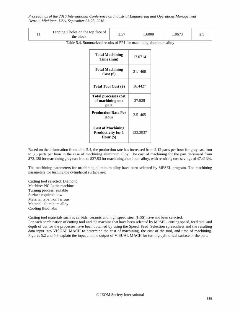
11 Tapping 2 holes on the top face of the block 3.57 1.6009 1.0673 2.5
Table 5.4. Summarized results of PP1 for machining aluminum alloy
Total Machining Time (min) 17.0714
Total Machining Cost ($) 21.1468
Total Tool Cost ($) 16.4427
Total processes cost of machining one
part 37.928
Production Rate Per Hour 3.51465
Cost of Machining Productivity for 1
Hour ($) 133.3037
Based on the information from table 5.4, the production rate has increased from 2.12 parts per hour for gray cast iron to 3.5 parts per hour in the case of machining aluminum alloy. The cost of machining for the part decreased from $72.128 for machining gray cast iron to $37.93 for machining aluminum alloy, with resulting cost savings of 47.413%.
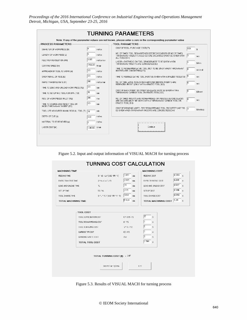
The machining parameters for machining aluminum alloy have been selected by MPSEL program. The machining parameters for turning the cylindrical surface are: Cutting tool selected: Diamond Machine: NC Lathe machine Turning process: suitable Surface required: low Material type: non ferrous Material: aluminum alloy Cooling fluid: kbs Cutting tool materials such as carbide, ceramic and high speed steel (HSS) have not been selected. For each combination of cutting tool and the machine that have been selected by MPSEL, cutting speed, feed rate, and depth of cut for the processes have been obtained by using the Speed_Feed_Selection spreadsheet and the resulting data input into VISUAL MACH to determine the cost of machining, the cost of the tool, and time of machining. Figures 5.2 and 5.3 explain the input and the output of VISUAL MACH for turning cylindrical surface of the part.
© IEOM Society International 639
Proceedings of the 2016 International Conference on Industrial Engineering and Operations Management Detroit, Michigan, USA, September 23-25, 2016
Figure 5.2. Input and output information of VISUAL MACH for turning process
Figure 5.3. Results of VISUAL MACH for turning process
© IEOM Society International 640
Proceedings of the 2016 International Conference on Industrial Engineering and Operations Management Detroit, Michigan, USA, September 23-25, 2016
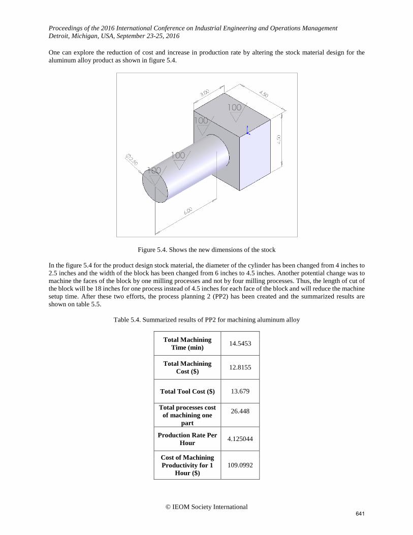
One can explore the reduction of cost and increase in production rate by altering the stock material design for the aluminum alloy product as shown in figure 5.4.
Figure 5.4. Shows the new dimensions of the stock
In the figure 5.4 for the product design stock material, the diameter of the cylinder has been changed from 4 inches to 2.5 inches and the width of the block has been changed from 6 inches to 4.5 inches. Another potential change was to machine the faces of the block by one milling processes and not by four milling processes. Thus, the length of cut of the block will be 18 inches for one process instead of 4.5 inches for each face of the block and will reduce the machine setup time. After these two efforts, the process planning 2 (PP2) has been created and the summarized results are shown on table 5.5.
Table 5.4. Summarized results of PP2 for machining aluminum alloy
Total Machining Time (min) 14.5453
Total Machining Cost ($) 12.8155
Total Tool Cost ($) 13.679
Total processes cost of machining one
part
26.448
Production Rate Per Hour 4.125044
Cost of Machining Productivity for 1
Hour ($) 109.0992
© IEOM Society International 641
Proceedings of the 2016 International Conference on Industrial Engineering and Operations Management Detroit, Michigan, USA, September 23-25, 2016
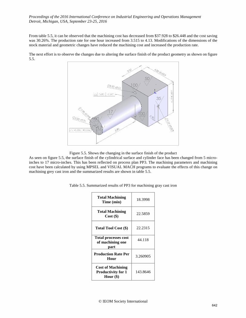
From table 5.5, it can be observed that the machining cost has decreased from $37.928 to $26.448 and the cost saving was 30.26%. The production rate for one hour increased from 3.515 to 4.13. Modifications of the dimensions of the stock material and geometric changes have reduced the machining cost and increased the production rate. The next effort is to observe the changes due to altering the surface finish of the product geometry as shown on figure 5.5.
Figure 5.5. Shows the changing in the surface finish of the product As seen on figure 5.5, the surface finish of the cylindrical surface and cylinder face has been changed from 5 micro-inches to 17 micro-inches. This has been reflected on process plan PP3. The machining parameters and machining cost have been calculated by using MPSEL and VISUAL MACH programs to evaluate the effects of this change on machining grey cast iron and the summarized results are shown in table 5.5.
Table 5.5. Summarized results of PP3 for machining gray cast iron
Total Machining Time (min) 18.3998
Total Machining Cost ($) 22.5859
Total Tool Cost ($) 22.2315
Total processes cost of machining one
part
44.118
Production Rate Per Hour 3.260905
Cost of Machining Productivity for 1
Hour ($) 143.8646
© IEOM Society International 642
Proceedings of the 2016 International Conference on Industrial Engineering and Operations Management Detroit, Michigan, USA, September 23-25, 2016
From the results shown on table 5.5 and by comparison with the values on table 5.2, the cost all machining processes have decreased from $72.128 to $44.118 and the cost saving was 38.834%. Production rate increased from 2.1196 to 3.261 parts per hour. The alteration of surface finish to retain functionality has had a good effect on cost and production rate. 6. Conclusion The results presented in this paper clearly show that computer aided iterative analysis of process plan developmental efforts can make a significant impact on cost and throughput. The CAPP approach should be tailored to specific product, process, and system attributes so as to be effective. The approach presented in this paper highlights the design modifications of the product retaining functionality in order to enable the development of the most effective process plans for manufacturing for utilization in the domain of concurrent engineering.
7. Acknowledgements The authors wish to thank the resources of the DoE supported Industrial Assessment Center at the Statler College of Engineering, Department of Industrial and Management Systems Engineering, West Virginia University.
8. References Banerjee, A., Feng, H., & Bordatchev, E. V. (2012). Process planning for floor machining of 2½D pockets based on
a morphed spiral tool path pattern. Computers & Industrial Engineering, 63(4), 971-979. Ciurana, J., Garcia-Romeu, M., Ferrer, I., & Casadesús, M. (2008). A model for integrating process planning and
production planning and control in machining processes. Robotics and Computer-Integrated Manufacturing, 24(4), 532-544.
Feng, S. C., & Song, E. Y. (2002). Preliminary design and manufacturing planning integration using intelligent agents. Paper presented at the Computer Supported Cooperative Work in Design, 2002. the 7th International Conference On, 270-275.
Goldhahn, L., & Eckardt, R. (2016). Sustainable process planning of manufacturing variants for high-precision parts. Procedia CIRP, 46, 344-347.
Ismail, N., Musharavati, F., Hamouda, A., & Ramli, A. R. (2008). Manufacturing process planning optimisation in reconfigurable multiple parts flow lines. Journal of Achievements in Materials and Manufacturing Engineering, 31(2), 671-677.
Kabir, Md Deloyer Jahan1 Golam. (2010). Development of computer aided process planning (CAPP) for rotational parts.
Kang, S., & Park, D. (2002). Application of computer-aided process planning system for non-axisymmetric deep drawing products. Journal of Materials Processing Technology, 124(1), 36-48.
Li, L., Fuh, J., Zhang, Y., & Nee, A. (2005). Application of genetic algorithm to computer-aided process planning in distributed manufacturing environments. Robotics and Computer-Integrated Manufacturing, 21(6), 568-578.
Makhe, A., & Frank, M. C. (2010). Polygon subdivision for pocket machining process planning. Computers & Industrial Engineering, 58(4), 709-716.
Pamphlet, A. (1966). Logistics machining data. Metcut Research Association Inc, Samadani, M., Behbahani, S., & Nataraj, C. (2013). A reliability-based manufacturing process planning method for
the components of a complex mechatronic system. Applied Mathematical Modelling, 37(24), 9829-9845. Shop floor practice. (1992). Economics of metal cutting hand out. Cincinnati: Metcut Research Association;.
© IEOM Society International 643
Proceedings of the 2016 International Conference on Industrial Engineering and Operations Management Detroit, Michigan, USA, September 23-25, 2016
Tepi, J., Todi, V., Luki, D., Milo, M., & BOROJEVI, S. (2011). Development of the computer-aided process planning (CAPP) system for polymer injection molds manufacturing. Metalurgija, 50(4), 273-277.
Tisza, M. (2007). Recent achievements in computer aided process planning and numerical modelling of sheet metal forming processes. Journal of Achievements in Materials and Manufacturing Engineering, 24(1), 435-442.
Wang, L. (2013). Machine availability monitoring and machining process planning towards cloud manufacturing. CIRP Journal of Manufacturing Science and Technology, 6(4), 263-273.
Wang, L. (2015). An overview of function block enabled adaptive process planning for machining. Journal of Manufacturing Systems, 35, 10-25.
Wang, S., Lu, X., Li, X., & Li, W. (2015). A systematic approach of process planning and scheduling optimization for sustainable machining. Journal of Cleaner Production, 87, 914-929.
Yusof, Y., & Latif, K. (2014). Survey on computer-aided process planning. The International Journal of Advanced Manufacturing Technology, 75(1-4), 77-89.
Zhang, Y., Bernard, A., Gupta, R. K., & Harik, R. (2014). Evaluating the design for additive manufacturing: A process planning perspective. Procedia CIRP, 21, 144-150.
Zhang, Z., Tang, R., Peng, T., Tao, L., & Jia, S. (2016). A method for minimizing the energy consumption of machining system: Integration of process planning and scheduling. Journal of Cleaner Production,
Biography Omar Al-Shebeeb is PhD student of Industrial and Management Systems Engineering (IMSE) at West Virginia University (WVU) and Graduate Teaching Assistant in the Manufacturing Lab of Industrial Engineering department. Omar Al-Shebeeb obtained his B.E degree in Production Engineering from the Production Engineering Department at University of Technology, Iraq, M.S. degree in Production Engineering from the Production Engineering Department at University of Technology, Iraq. His areas of research interests are productivity improvement and design for manufacturing.
Bhaskaran Gopalakrishnan is a Professor of Industrial and Management Systems Engineering (IMSE) at West Virginia University (WVU) and Director of the Industrial Assessment Center (IAC) funded by the US DOE. Through the IAC and as a private consultant, he has conducted numerous industrial and energy assessments as well as plant wide energy assessments for manufacturing facilities and has published widely in this field. Dr. Gopalakrishnan obtained his B.E. (Hons) degree in Production Engineering from the College of Engineering at Guindy, University of Madras, India, M.S. degree in Operations Research from Southern Methodist University, and Ph.D degree in Industrial Engineering and Operations Research from Virginia Tech. He is a Certified Energy Manager (CEM) certified by the Association of Energy Engineers, Atlanta, Certified Practitioner in Energy Management Systems (CPEnMS), and a US DOE Qualified AirMaster+ Specialist, SSAT Qualified Specialist, FSAT Qualified Specialist, PSAT Qualified Specialist, PHAST Qualified Specialist, and a LEED Green Associate. He is a registered Professional Engineer (PE) in the State of West Virginia. His areas of research interests are in industrial energy conservation, waste reduction, and productivity improvement. Email: [email protected]
© IEOM Society International 644
![A“Hybrid” Approachfor Synthesizing Optimal Controllers of ... · reported in [3] based on game theory and model checking. Keywords: Hybrid System, Optimal Control, Quantifier](https://img.pdfslide.net/doc/110x75/5e176173a9d5b249e5069d18/aaoehybrida-approachfor-synthesizing-optimal-controllers-of-reported-in-3.jpg)