Embed Size (px)
Citation preview
Computer ArchitectureComputer ArchitectureCST 250CST 250
Hard Disk
Prepared by: Omar Hirzallah
Contents
• Hard disk drive• Schematic picture• Disk organization• File organization• Hard disk characteristics • Hard disk controllers• SAS & SATA• Encoding Schemes (MFM & RLL)
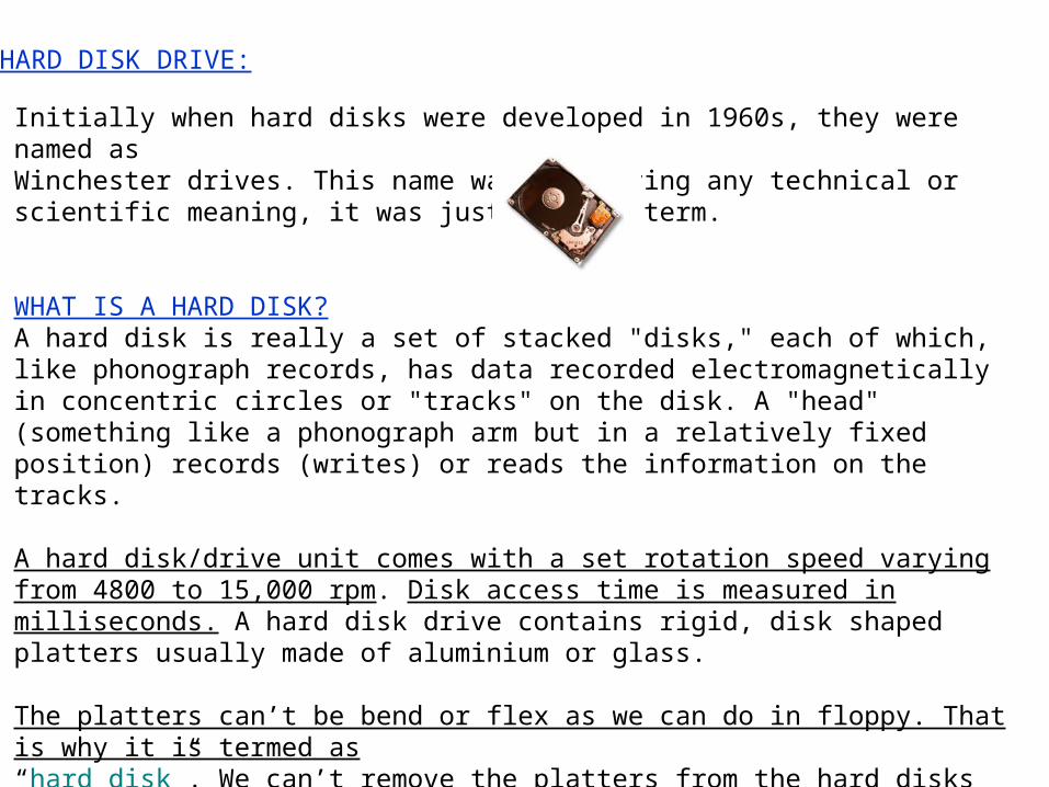
HARD DISK DRIVE:
Initially when hard disks were developed in 1960s, they were named as Winchester drives. This name was not having any technical or scientific meaning, it was just a slang term.
WHAT IS A HARD DISK?A hard disk is really a set of stacked "disks," each of which, like phonograph records, has data recorded electromagnetically in concentric circles or "tracks" on the disk. A "head" (something like a phonograph arm but in a relatively fixed position) records (writes) or reads the information on the tracks.
A hard disk/drive unit comes with a set rotation speed varying from 4800 to 15,000 rpm. Disk access time is measured in milliseconds. A hard disk drive contains rigid, disk shaped platters usually made of aluminium or glass.
The platters can’t be bend or flex as we can do in floppy. That is why it is termed as“hard disk”. We can’t remove the platters from the hard disks in most of the casesthat is why they are also termed as “Fixed Disk”.
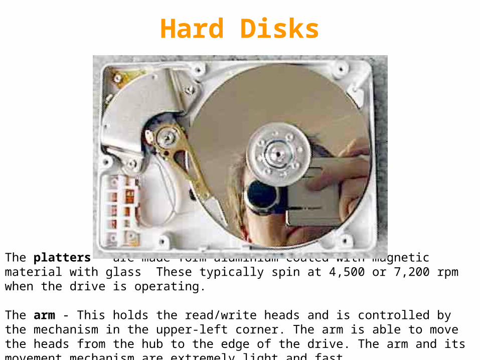
The platters – are made form aluminium coated with magnetic material with glass These typically spin at 4,500 or 7,200 rpm when the drive is operating.
The arm - This holds the read/write heads and is controlled by the mechanism in the upper-left corner. The arm is able to move the heads from the hub to the edge of the drive. The arm and its movement mechanism are extremely light and fast.
Hard Disks
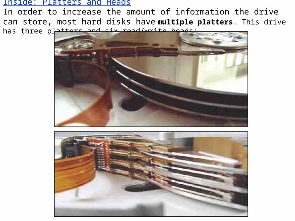
Inside: Platters and HeadsIn order to increase the amount of information the drive can store, most hard disks have multiple platters. This drive has three platters and six read/write heads:
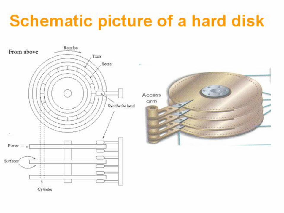
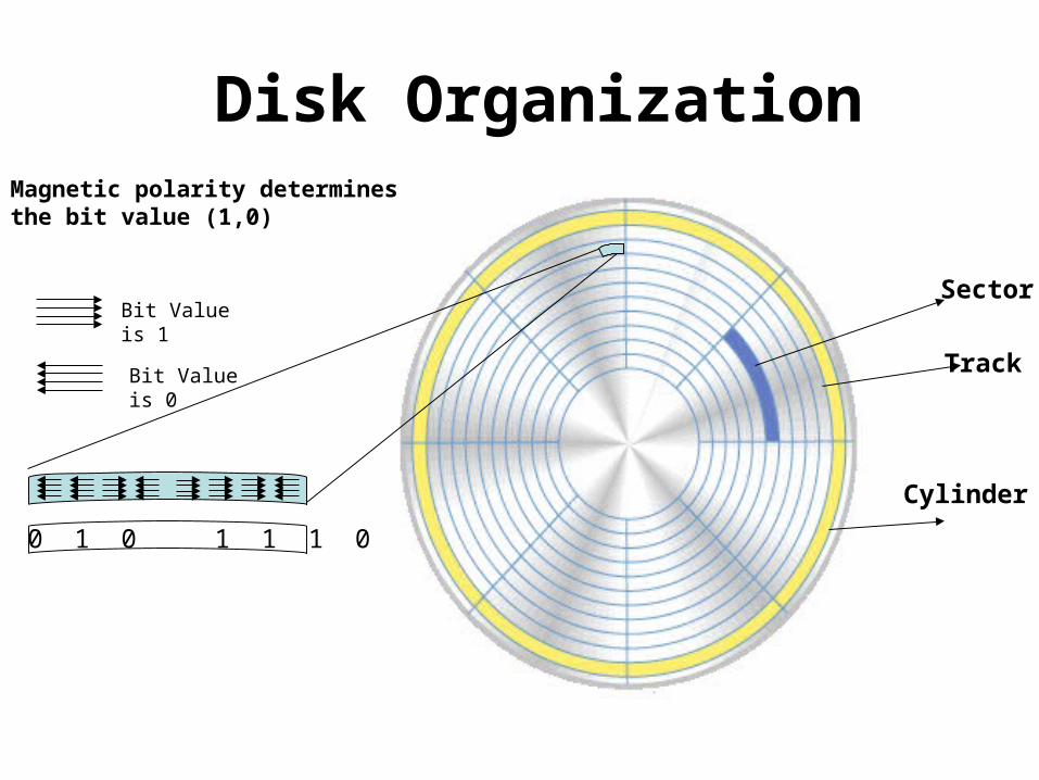
Sector
Cylinder
Track
Magnetic polarity determines the bit value (1,0)
Bit Value is 1
Bit Value is 0
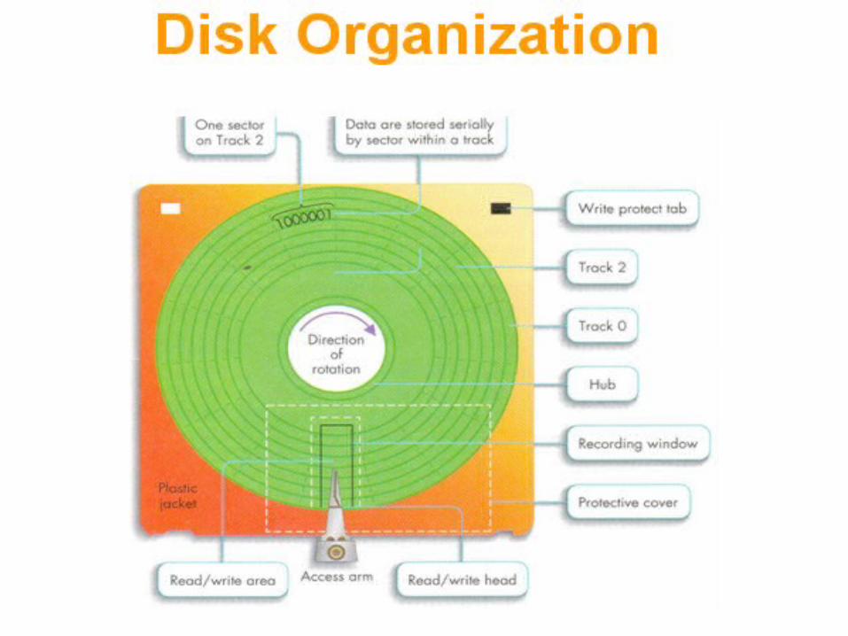
Disk Organization
0 0 1 0 1 1 1 0
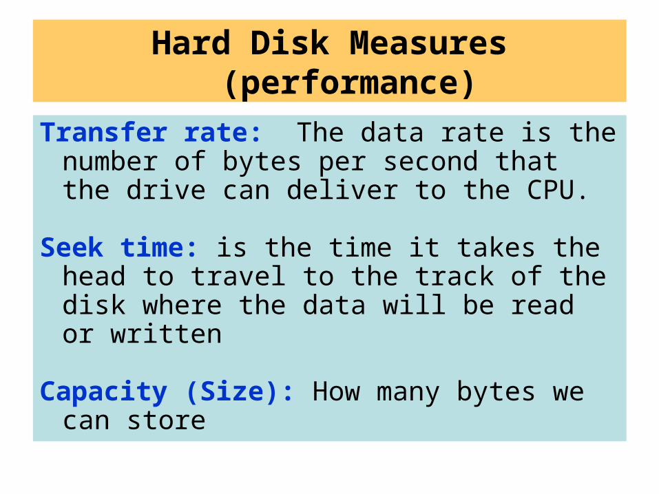
Hard Disk Measures (performance)
Transfer rate: The data rate is the number of bytes per second that the drive can deliver to the CPU.
Seek time: is the time it takes the head to travel to the track of the disk where the data will be read or written
Capacity (Size): How many bytes we can store
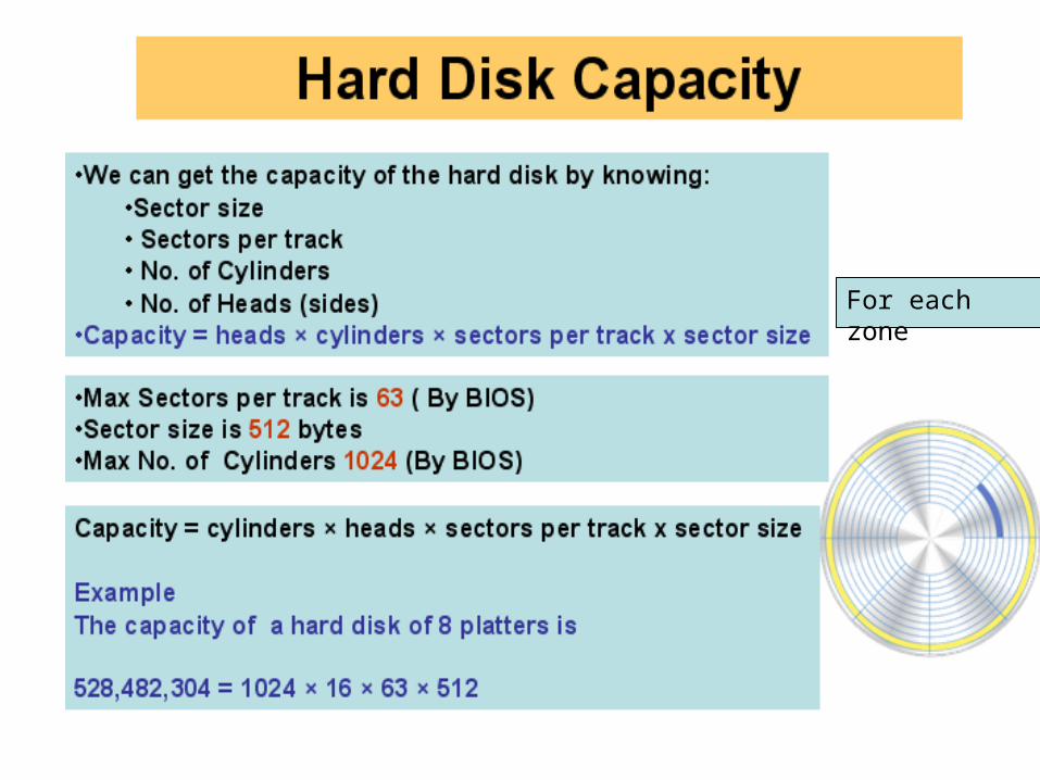
For each zone
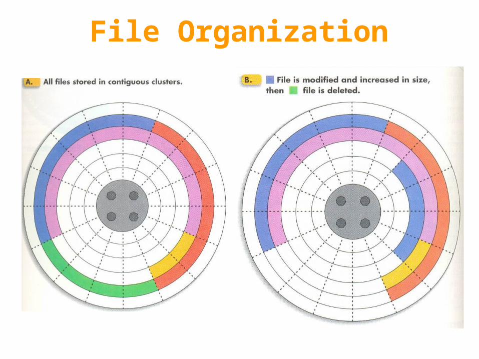
File Organization
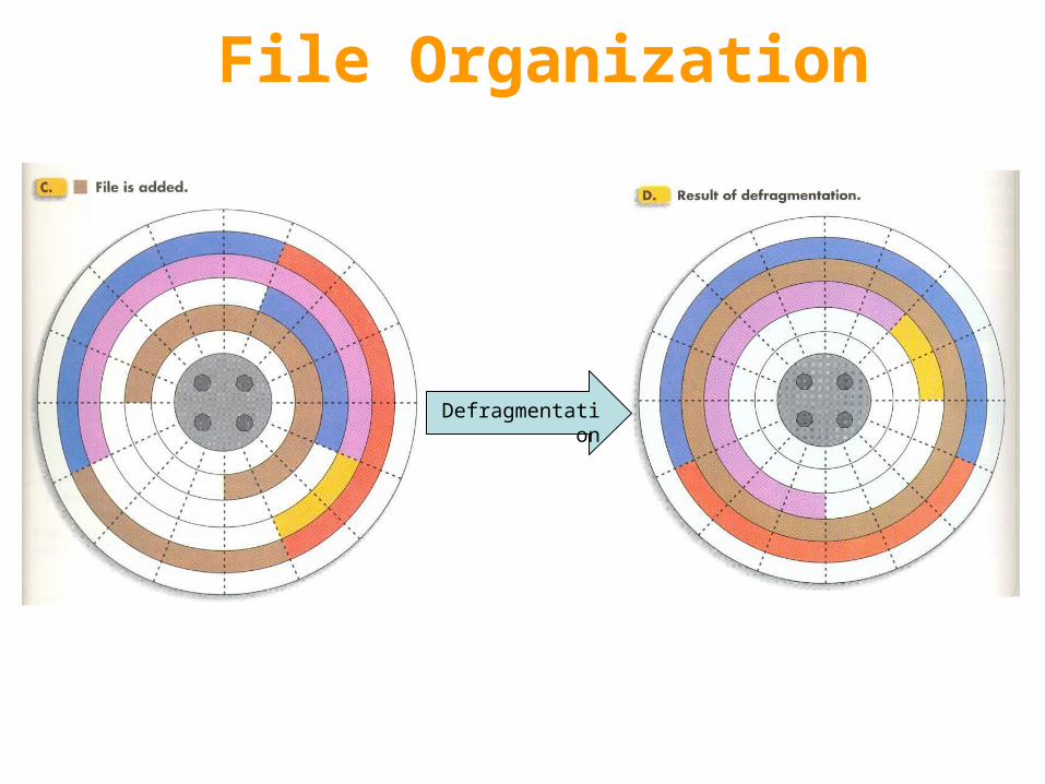
File Organization
Defragmentation
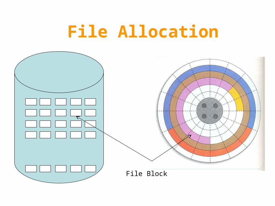
File Allocation
File Block
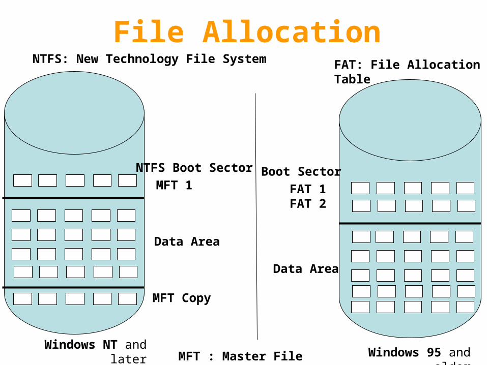
File Allocation
Windows 95 and olderWindows NT and later
Boot Sector
FAT 1FAT 2
Data Area
NTFS Boot Sector
MFT 1
Data Area
MFT Copy
NTFS: New Technology File System FAT: File Allocation Table
MFT : Master File Table
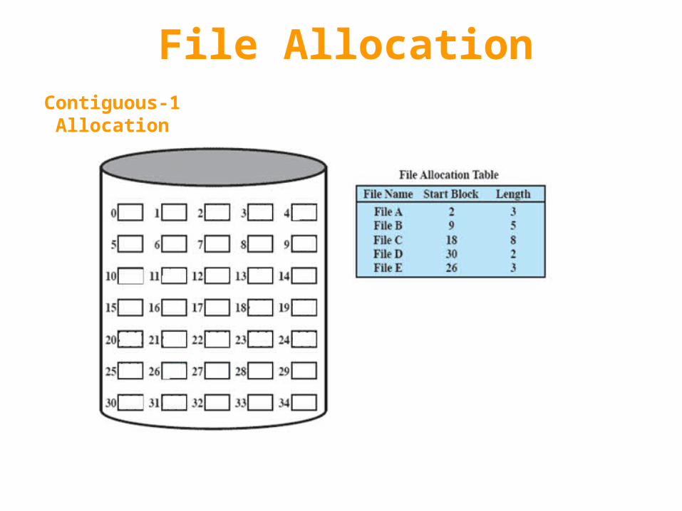
File Allocation
Boot Sector
1-Contiguous Allocation
File Allocation
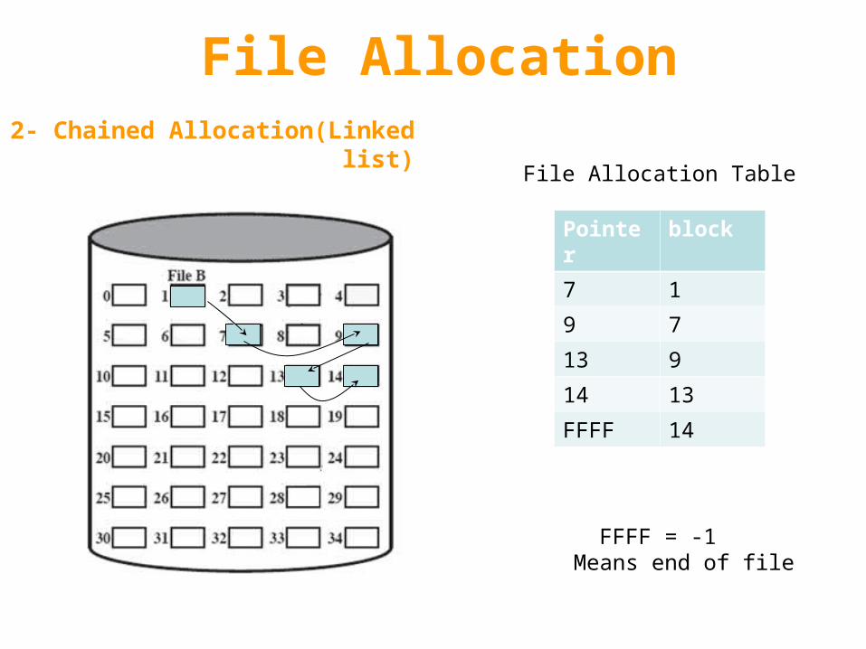
2- Chained Allocation(Linked list)
blockPointer
17
79
913
1314
14FFFF
File Allocation Table
FFFF = -1 Means end of file
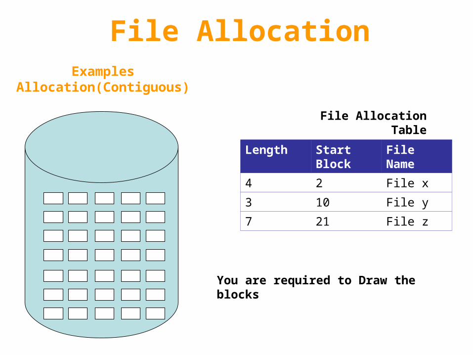
File AllocationExamples
Allocation(Contiguous)
File NameStart Block
Length
File x24
File y103
File z217
File Allocation Table
You are required to Draw the blocks
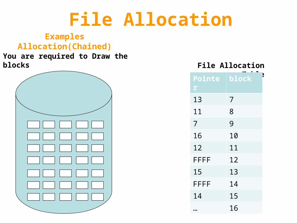
File AllocationExamples Allocation(Chained)
File Allocation Table
blockPointer
713
811
97
1016
1112
12FFFF
1315
14FFFF
1514
16…
You are required to Draw the blocks
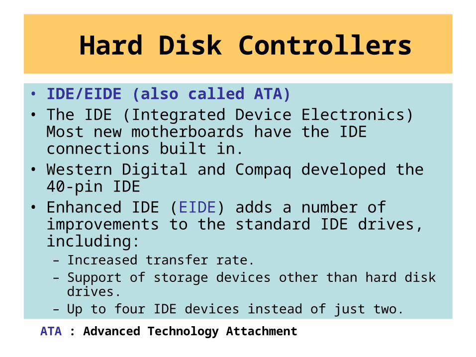
Hard Disk Controllers
• IDE/EIDE (also called ATA)• The IDE (Integrated Device Electronics) Most new
motherboards have the IDE connections built in.• Western Digital and Compaq developed the 40-pin IDE• Enhanced IDE (EIDE) adds a number of improvements
to the standard IDE drives, including:– Increased transfer rate. – Support of storage devices other than hard disk drives. – Up to four IDE devices instead of just two.
ATA : Advanced Technology Attachment
Hard Disk Controllers
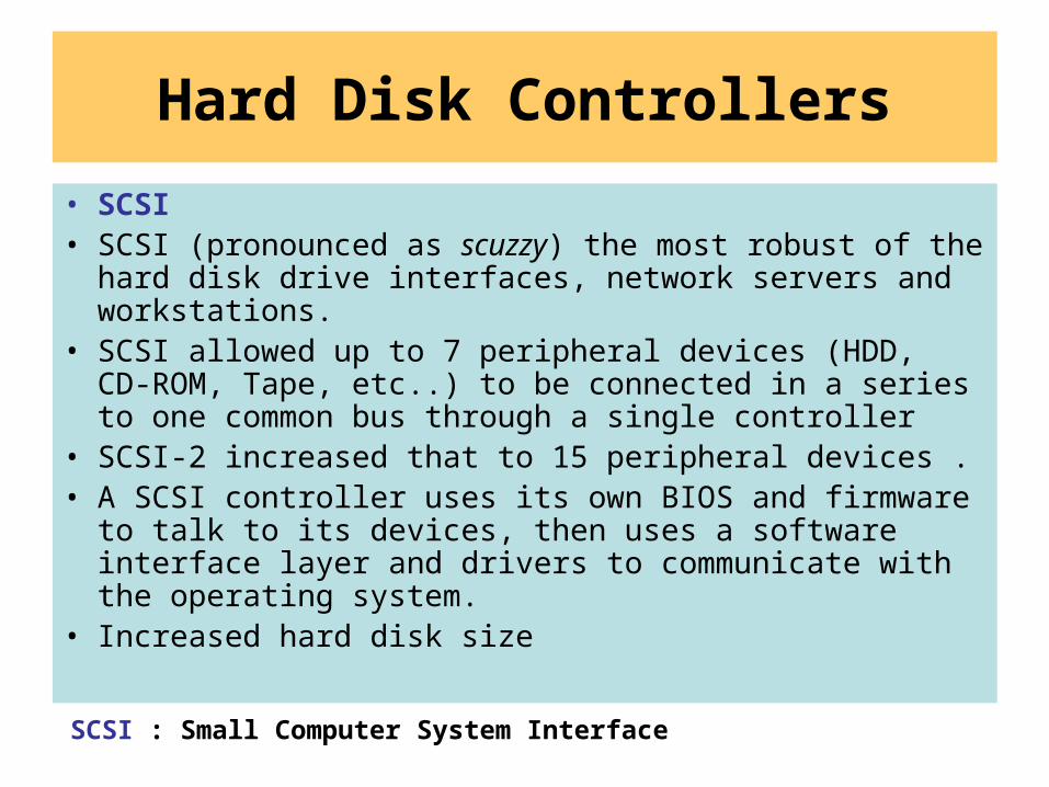
• SCSI• SCSI (pronounced as scuzzy) the most robust of the
hard disk drive interfaces, network servers and workstations.
• SCSI allowed up to 7 peripheral devices (HDD, CD-ROM, Tape, etc..) to be connected in a series to one common bus through a single controller
• SCSI-2 increased that to 15 peripheral devices .• A SCSI controller uses its own BIOS and firmware to talk
to its devices, then uses a software interface layer and drivers to communicate with the operating system.
• Increased hard disk size
SCSI : Small Computer System Interface
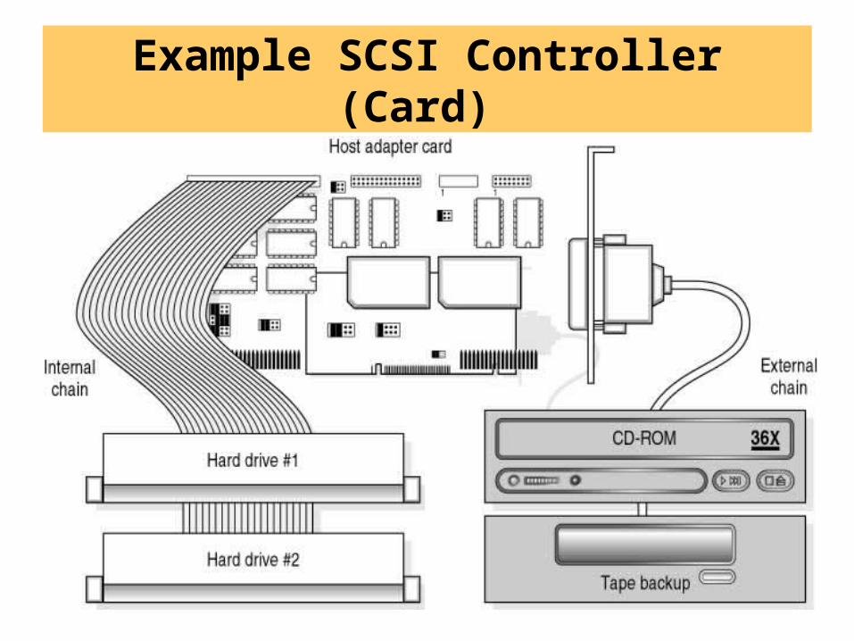
Example SCSI Controller (Card)
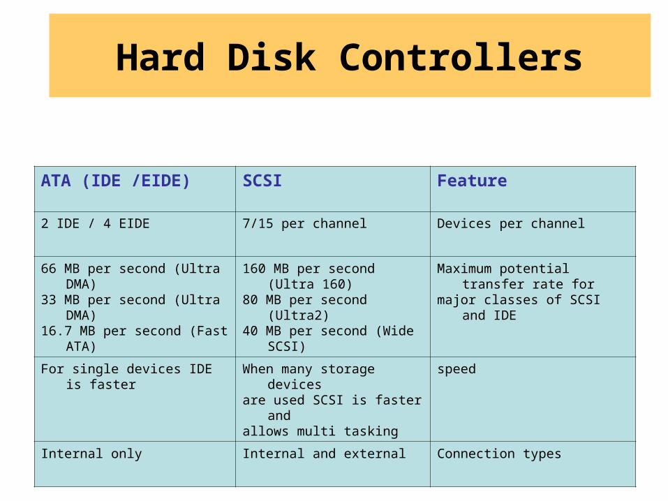
FeatureSCSIATA (IDE /EIDE)
Devices per channel7/15 per channel2 IDE / 4 EIDE
Maximum potential transfer rate formajor classes of SCSI and IDE
160 MB per second (Ultra 160)80 MB per second (Ultra2)40 MB per second (Wide SCSI)
66 MB per second (Ultra DMA)33 MB per second (Ultra DMA)16.7 MB per second (Fast ATA)
speedWhen many storage devicesare used SCSI is faster andallows multi tasking
For single devices IDE is faster
Connection typesInternal and externalInternal only
Hard Disk Controllers
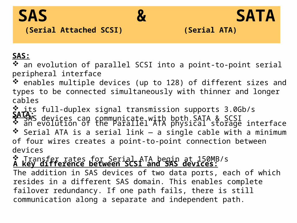
SAS & SATA )Serial Attached SCSI( )Serial ATA(
SAS: an evolution of parallel SCSI into a point-to-point serial peripheral interface enables multiple devices (up to 128) of different sizes and types to be connected simultaneously with thinner and longer cables its full-duplex signal transmission supports 3.0Gb/s SAS devices can communicate with both SATA & SCSI
SATA: an evolution of the Parallel ATA physical storage interface Serial ATA is a serial link — a single cable with a minimum of four wires creates a point-to-point connection between devices Transfer rates for Serial ATA begin at 150MB/s
A key difference between SCSI and SAS devices: The addition in SAS devices of two data ports, each of which resides in a different SAS domain. This enables complete failover redundancy. If one path fails, there is still communication along a separate and independent path.
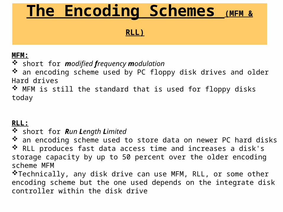
The Encoding Schemes (MFM & RLL)
MFM: short for modified frequency modulation an encoding scheme used by PC floppy disk drives and older Hard drives MFM is still the standard that is used for floppy disks today
RLL: short for Run Length Limited an encoding scheme used to store data on newer PC hard disks RLL produces fast data access time and increases a disk's storage capacity by up to 50 percent over the older encoding scheme MFMTechnically, any disk drive can use MFM, RLL, or some other encoding scheme but the one used depends on the integrate disk controller within the disk drive
References Mano, (2008). Logic and Computer Design Fundamentals, 4th ed., Prentice-Hall.
Mano, (2006),Digital Design, 4th ed, Prentice Hall.
Kifer, M., &Smolka, S. A. (2007).Introduction to Operating System Design and Implementation, Springer
http://www.webopedia.com/TERM/M/microprocessor.html
www.webopedia.com/TERM/I/Intel.html
www.webopedia.com/TERM/C/cache.html
www.webopedia.com/quick_ref/ memory.asp
http://en.wikipedia.org/wiki/Booting
www.pcguide.com/ref/mbsys/res/irq/index.htm
en.wikipedia.org/wiki/Bus_(computing)
en.wikipedia.org/wiki/Addressing_mode
www.cse.dmu.ac.uk/~msaf/CHIP.htm