Embed Size (px)
Citation preview

Computer Buses Page 1
Computer Buses
What is a bus? A group of electrical lines/wires that carry computer signals.
a bus is a shared transmission medium
Lines are assigned names for identification. Each carries a single electrical signal e.g. 1 bit memory
address, a sequence of data bits, or timing control that turns a device on or off
It possible to transfer data from one location in the computer system to another (between various
I/O modules, memory and the CPU)
Buses are notated on diagrams using widened lines or with a number to indicate the number of
separate lines
The bus is not only cable connection but also hardware (bus architecture), protocol, software, and
bus controller
Bus Structure and Topologies Lines are grouped as follows
1. Power line provide electrical power to attached components
2. Data lines carrying the data or instructions between system modules
3. Address lines specify the recipient of data on the bus
4. Control lines provide control for the synchronization and operation of the bus and of the modules
that are connected to the bus

Computer Buses Page 2
Figure 1: System Bus
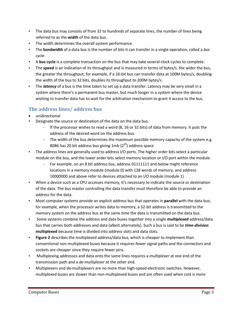
System Bus • A system bus connects major computer components (processor, memory, I/O)
• All memory and memory-mapped I/O devices are connected to this bus.
• Such a bus has to be able to operate at the speed of the fastest device connected to it—normally
the main store. It can prove expensive when lots of low-speed peripherals are connected to it
because they have to have high-speed interfaces whether they actually need them or not.
• A system bus consists of typically, of from about 50 to hundreds of separate lines.
• The system bus is made up of the address, data and control paths from the CPU. In addition, there
may be power distribution lines that supply power to the attached modules.
Elements of Bus Design Design elements that serve to classify and differentiate buses
• Bus types
• Dedicated bus line is permanently assigned either to one function or to a physical subset of
computer components
• Multiplexed bus address and data information may be transmitted over the same set of lines
using an Address Valid control line
• A bus transaction includes two parts: Issuing the command (and address) – request and
transferring the data – action
• Master is the one who starts the bus transaction by: issuing the command (and address)
• Slave is the one who responds to the address by: Sending data to the master if the master ask
for data Receiving data from the master if the master wants to send data
Data lines/ data bus • Bi-directional
• The data lines provide a path for moving data between system modules.
System bus
Memory I/O controllerI/O controller
Disk drive CRT controller
Peripheral device
Address, dataand control signals
Bus master
Bus slave
Localmemory
CPU
Local bus
Peripheral device
Bus masterBus slave
Peripheralbus
Computer Buses Page 3
• The data bus may consists of from 32 to hundreds of separate lines, the number of lines being
referred to as the width of the data bus.
• The width determines the overall system performance.
• The bandwidth of a data bus is the number of bits it can transfer in a single operation, called a bus
cycle.
• A bus cycle is a complete transaction on the bus that may take several clock cycles to complete.
• The speed is an indication of its throughput and is measured in terms of bytes/s. the wider the bus,
the greater the throughput; for example, if a 16-bit bus can transfer data at 100M bytes/s, doubling
the width of the bus to 32 bits, doubles its throughput to 200M bytes/s.
• The latency of a bus is the time taken to set up a data transfer. Latency may be very small in a
system where there’s a permanent bus master, but much longer in a system where the device
wishing to transfer data has to wait for the arbitration mechanism to grant it access to the bus.
The address lines/ address bus unidirectional
• Designate the source or destination of the data on the data bus.
– If the processor wishes to read a word (8, 16 or 32 bits) of data from memory. It puts the
address of the desired word on the address bus.
– The width of the bus determines the maximum possible memory capacity of the system e.g.
8086 has 20 bit address bus giving 1mb (220) address space
• The address lines are generally used to address I/O ports. The higher order bits select a particular
module on the bus, and the lower order bits select memory location or I/O port within the module.
– For example, on an 8 bit address bus, address 01111111 and below might reference
locations in a memory module (module 0) with 128 words of memory, and address
10000000 and above refer to devices attached to an I/O module (module 1)
• When a device such as a CPU accesses memory, it’s necessary to indicate the source or destination
of the data. The bus master controlling the data transfer must therefore be able to provide an
address for the data.
• Most computer systems provide an explicit address bus that operates in parallel with the data bus;
for example, when the processor writes data to memory, a 32-bit address is transmitted to the
memory system on the address bus at the same time the data is transmitted on the data bus.
• Some systems combine the address and data buses together into a single multiplexed address/data
bus that carries both addresses and data (albeit alternately). Such a bus is said to be time-division
multiplexed because time is divided into address slots and data slots.
• Figure 2 describes the multiplexed address/data bus, which is cheaper to implement than
conventional non-multiplexed buses because it requires fewer signal paths and the connectors and
sockets are cheaper since they require fewer pins.
• Multiplexing addresses and data onto the same lines requires a multiplexer at one end of the
transmission path and a de-multiplexer at the other end.
• Multiplexers and de-multiplexers are no more than high-speed electronic switches. However,
multiplexed buses are slower than non-multiplexed buses and are often used when cost is more

Computer Buses Page 4
important than speed. This is especially true when the multiplexing and de-multiplexing is built into
the processors and interface components themselves.
Figure 2: Multiplexing address and data
Burst Transfers
• The efficiency of both non-multiplexed and multiplexed address buses can be improved by
operating them in a burst mode in which a sequence of data elements is transmitted to consecutive
memory addresses.
• Burst-mode operation is widely used to support cache memory systems. When a line in a cache is to
be loaded from memory, the address of the first word is transmitted to the memory. The memory
responds by providing the word at the specified address, followed by the word at the next address
in sequence, and so on. These sequential addresses can be generated at the memory.
• Figure 3 illustrates the concept of burst mode addressing where an address is transmitted for
location i and data for locations i, i+1, i+2, and i+3 are transmitted without a further address
Combined address and data bus
Bus master Bus slave
Multiplexer Demultiplexer
Address AddressData DataSeparate addressand data buses
addressdata data data dataaddressaddress address data

Computer Buses Page 5
Figure 3: Burst Mode and Data
The control lines (control bus) • Bidirectional
• The lines are used to control the access to and the use of the data and address lines.
• The bus transmits both command and timing information between system modules.
• Timing signals indicate the validity of data and address information.
• Command signals specify operations to be performed.
• Figure 4 describes the simplest synchronous control bus that requires two signals: a data-direction
signal and a data-validation signal. (DAV)
• The data direction signal is often called R/W and is high to indicate a read operation and low to
indicate a write operation (the direction of data transfer is specified with respect to the bus master
that originated the data transfer).
• During a read cycle, data flows from the bus slave to the bus master and during a write cycle data
flows from the master to the slave.
Figure 4: Minimal bus control signals
Address i Address i+4
Data Data Data Data Data Data Data Data
i i+1 i+2 i+3 i+4 i+5 i+6 i+7
Addressbus
Databus
Address bus
Data bus
Control bus
Bus master Bus slave
R/W R/WDAV DAV
R/W = 1 for readR/W = 0 for write
DAV = 0 indicatesdata valid

Computer Buses Page 6
• Some systems have separate read and write strobes, READ and WRITE, rather than a composite
R/W signal.
• Individual READ and WRITE signals have the advantage that they can indicate three bus states:
– an active read state, an active write state, and a bus free state (READ and WRITE both
negated).
• A composite R/W signal introduces an ambiguity because when R/W = 0 the bus is always executing
a write operation, whereas when R/W = 1 either a read operation is being executed or the bus is
free.
• The active-low data valid signal, DAV, in the above diagram is asserted by the bus master to indicate
that a data transfer is taking place.
Typical Control Signal lines
1. Memory write- causes data on the bus to be written into the addressed location
2. Memory read – causes data from the addressed location to be placed on the bus
3. I/O write – causes data on the bus to be output to the addressed I/O port
4. I/O read - causes data from the addressed I/O port to be placed on the bus
5. Clock- used to synchronize operations
6. Reset –initializes all modules
7. Transfer ACK- indicates that data have been accepted from or placed on the bus
8. Bus request – indicates that a module needs to gain control of the bus
9. Bus Grant – indicates the a request in module has been granted control of the bus
10. Interrupt request – indicates that an interrupt is pending
11. Interrupt ACK – acknowledges that the pending interrupt has been recognized
The operation of a Bus
If a module wishes to send data to another it must:
1. Obtain the use of the bus and
2. Transfer data via bus.
If one module wishes to request data from another module, it must
1. Obtain the use of the bus and
2. Transfer a request to the other module over the appropriate control and address lines.
It must then wait for that second module to send the data
Bus Master • a bus master is any device that can take possession of the bus and control the flow of data over the
bus. A bus master may not necessarily use the data bus itself; for example, it may take control of the
bus on behalf of some other agent.
• The CPU is the permanent bus master or bus controller and only the CPU can put data on the bus or
invite memory/peripherals to supply data via the bus.
• The address bus, data bus, and control bus are often lumped together and called "the bus".
• Only one device at a time can put data on the data bus.

Computer Buses Page 7
• The following diagram shows how a bus can be subdivided into functional units such as an address
bus that specifies a location in memory that is to be read from or written to, the data bus that
copies data from one point in the system to another, and the control bus.
• Sometimes the control bus refers to the signals that control the flow of information during a read or
write cycle.
• Sometimes the control bus refers to an entirely separate sub-bus that performs special functions
such as interrupt control or arbitration.
The structure of a general-purpose bus
Bus Slave • The system that controls the bus is called the bus master and the system that is accessed by the bus
master is known as the bus slave.
• At any instant, there can be only one active bus master, because buses cannot support multiple
simultaneous transactions.
• However, a bus can support multiple bus slaves simultaneously if the bus master broadcasts
information to several slaves.
• Buses like the PCI bus increase throughput by allowing so-called split transactions in which one bus
master accesses the bus and then another bus master uses the bus before the first bus master has
completed its transaction. Consequently, two or more bus masters can be active during a data
transfer and their data transfers may overlap. No two bus masters can, of course, drive the bus at
the same instant.
The system bus
Address bus
Data bus
Control bus
Bus masterBus master Bus slaveBus slave

Computer Buses Page 8
Bus Arbitration • More than one module may need control of the bus. e.g. CPU and DMA controller
• I/O module may need to read or write directly to memory, without sending the data to the
processor.
• The process by which multiple requests are recognized and priority given to one of them is called
arbitration.
• Arbitration mechanisms can be centralized/localised or decentralized/distributed
Centralized arbitration
• In localized arbitration, an arbitration circuit receives requests from the contending bus masters and
then decides which of them is to be given control of the bus.
• A single hardware device, known as a bus controller or arbiter, is responsible for allocating time to
bus.
• The device may be part of CPU or separate module
• E.g. Daisy chaining
Distributed arbitration
• There is no central controller each module may claim the bus
• All devices monitor all the request lines
• In a system with distributed arbitration, each of the masters takes part in the arbitration process
• The system lacks a specific arbiter—each master monitors the other masters and decides whether to
continue competing for the bus or whether to give up and wait until later.
Releasing the Bus • The requester may implement one of two options for releasing the bus. One is called option RWD,
release when done, and the other option ROR, release on request.
• RWD, requires that the requester will release the bus as soon as the on-board master stops
indicating bus busy. In other words, the master remains in control of the bus until its task has been
completed. This situation can, of course, lead to undue bus hogging.
• The ROR option is more suitable in systems in which it is unreasonable to grant unlimited bus access
to a master.
• The ROR requester monitors the four bus request lines. If it sees that another requester has
requested service, it releases its BUSY output and defers to the other request.
• The ROR option reduces the number of arbitrations requested by a master, as the bus is frequently
cleared voluntarily
Timing Timing refers to the way in which events are coordinated on the bus. Buses use either synchronous
timing or asynchronous timing.
Synchronous bus: • Includes a clock in the control lines • A fixed protocol for communication that is relative to the clock

Computer Buses Page 9
• Advantage: involves very little logic and can run very fast • Disadvantages: Every device on the bus must run at the same clock rate and To avoid clock skew,
they cannot be long if they are fast
Synchronous Timing
• The occurrence of events on the bus is determined by a clock. The bus includes a clock line which
transmits a regular sequence of alternating 1’s and 0’s of equal duration
• A single 1-0 transmission is a clock cycle or bus cycle and defines a time slot
• All devices on the bus can read clock line, and all events start at the beginning of a clock cycle.
• Other bus signals may change at the leading edge of the clock signal (with slight delay)
• Most events Usually occupy a single clock cycle
Figure 5: Synchronous Timing Diagram
• The processor places a memory address on the address lines during the first clock cycle (T1), and
may assert various status lines.
• Once the address lines have stabilized the processor issues an address enable signal (T1).
• For a read operation, the processor issues a read command at the start of the second cycle T2).
• A memory module recognizes the address and after delay of one cycle, places the data on the data
lines (T3)
• For a write operation, the processor puts the data on the data lines at the start of the second cycle
(T2) and issues a write command after the data lines have stabilized
• The memory module copies the information from the data lines during the third clock cycle.

Computer Buses Page 10
Asynchronous Timing
• The occurrence of one event on a bus follows and depends on the occurrence of a previous event.
Figure 6: Asynchronous Timing – system bus read cycle
• The processor places address and status signals on the bus.
• After the signals have stabilized the processor issues a read command, indicating the presence of
valid address and control signals.
• The appropriate memory decodes the address and responds by placing the data on the data line
• Once the data line has stabilized, the memory module asserts the acknowledged line to signal the
processor that the data is available.
• Once the master has read the data from the data lines, it de-asserts the read signal. This causes the
memory module to drop the data and acknowledge lines.
Figure 7: Asynchronous Timing – System bus Write

Computer Buses Page 11
• The master places the data on the data line at the same time that it puts signals on the status and
address lines.
• The memory module responds to the write command by copying the data from the data lines and
then asserting the acknowledge line.
• The master then drops the write signal and the memory module drops the acknowledge signal.
• Synchronous timing is simpler to implement and test, however,
• It is less flexible than asynchronous timing, because all devices on a synchronous bus are tied to a
fixed clock rate, the system cannot take advantage of advances in device performance.
• With asynchronous timing, a mixture of slow and fast devices, using older and newer technology,
can share a bus.
Data transfer type • A bus supports various data transfer types. All buses support both write (master to slave) and read
(slave to master) transfers
• For multiplexed address/data bus, the bus is first used for specifying the address and then for
transferring the data.
• For read operation there is typically a wait while the data is being fetched from the slave to be put
on the bus.
• For either a read or write, there may also be a delay if it is necessary to go through arbitration to
gain control of the bus for the remainder of the operation(i.e. seize the bus to request a read or
write, then seize the bus again to perform a read or write)
• There are also some combination operations that some buses allow
• Read-modify write – operation is a read followed immediately by a write to the same address
• Read –after-write write followed immediately by a read from the same address
• Block – one address cycle is followed by n data cycles. The first data item is transferred to or from
the specified address; the remaining data items are transferred to or from subsequent addresses.
A Bus may connect modules together in various ways:
Point –to-point • A cable that connects the parallel or serial port in a PC from the computer to a printer
• P2P are intended for connection to a plug in device called ports
• Does not require address since destination is already known
Multipoint bus • Also called multi drop/broadcast burst
• Connects several points together
• Signals produced by a source on the bus are “broadcast” to every other point on the bus e.g.
Ethernet network

Computer Buses Page 12
• Requires addressing signals on the bus to identify the desired destination that is being addressed by
the source at a particular time
Bridges • The interfaces between different buses are called bus interface units or bridges
• Bridges make it possible for different buses to communicate with each other
• The external CPU bus is a Peripheral Control Interface (PCI) bus, Accelerated Graphic Processor
(AGP) bus and Industry Standard Architecture (ISA) bus are all part of the backplane
• The external CPU bus connects the CPU to the main memory and to the PCI bridge
• The PCI bridge connects the external CPU to AGP bridge, ISA bridge, USB port interface and disk
controller
• The AGP bus connects the PCI bus to the video card
• The ISA bus connects the PCI to parallel port interface and serial port interface
I/O Bus • Connects I/O devices, no direct processor interface
• The length and number of devices connected affects the speed and the bandwidth
• Industry standard
• Bridge connects these buses
Design Goals • Performance
• Standardization: flexibility in dealing with many devices
• Cost
– Memory bus emphasize performance, then cost
– I/O buses emphases standardization, then performance
Design Issues • Band width
– The bandwidth determines the cost
• multiplexing: Address and data on same lines
– Cheaper
– Less bandwidth
• Burst Transfers
– Multiple sequential data transactions for single address
– Increase bandwidth at relatively little cost
• Clocking: bus clocked or not?
– Synchronous: clocked

Computer Buses Page 13
– Fast
– Must be short to minimize clock skew
– Asynchronous: un-clocked
– Larger no clock skew, deals with devices of different speeds
– Slower requires “handshaking protocol”
– For example asynchronous read
– Processor drives address onto bus asserts request line
– Memory asserts ACK line, processor stops driving
– Memory drives data on bus, asserts DataReady line
– Processor asserts ACK line, memory stops driving
• Source synchronous
– A hybrid: send clock with data
• Trend is away from asynchronous buses
• Switching: how/when bus control is acquired and released
• Arbitration: deciding who gets the bus next
– New Trend : Point- to - Point buses
– Pro: No arbitration, no “master”, fast, simple, source synchronous
– Con: needs lots of wires or requires high-per wire bandwidth
Standard Bus Examples
PCI SCSI USB
Type Backplane I/O- disks I/O
Width 32-64 bits 8-32 bits 1 bit
Multiplexed? Yes Yes Yes
Clocking 33(66) MHz 5(10)MHz Asynchronous
Data rate 133(266)MB/s 10(20)MB/s 0.2,1.5,80MB/s
Arbitration Parallel Self selection Daisy-chain
Min Masters 1024 7-31 127
Min Length 0.5m 2.5m -

Computer Buses Page 14


![[Bos Lines ] Bus Lines (Conl'd) ) Buses—CliarlBr ] [Buses](https://img.pdfslide.net/doc/110x75/61cb52f5cae34a654467d956/bos-lines-bus-lines-conld-busescliarlbr-buses.jpg)
![[How to] Stickers and Labels Using Multiple Cut Lines](https://img.pdfslide.net/doc/110x75/6282550a21250500752b983e/how-to-stickers-and-labels-using-multiple-cut-lines.jpg)