Embed Size (px)
Citation preview

432
5
6
EESFC
Computer ControlledPhotovoltaic Solar Energy Unit
TeachingTechnique
used
Always included in the supply:
DataAcquisition
Board Control
Interface Box Software for:
- Data Acquisition- Data Management
- Computer Control
Cables and Accessories Manuals
SCADA. EDIBON Computer Control System
Computer(not included in the supply)
PROCESS DIAGRAM AND ELEMENTS ALLOCATION
OPEN CONTROL+
MULTICONTROL+
REAL TIME CONTROL
Technical Teaching Equipment
Worlddidac Quality Charter Certificate
WorlddidacMember
ISO 9001:2000Certificate of Approval
European Union Certificate
Worlddidac Member
Certificates ISO 14001: 2004 andECO-Management and Audit Scheme
(environmental management)
SCADA. EDIBON Computer Control System:Computer Control + Data Acquisition + Data Management
Sensors
Teaching unit
ControlInterface
Box
1
2
3
45
6“n”
Studentpost
Dat
aac
quis
ition
boar
dCableto
computerSoftware for:-Computer Control-Data Acquisition-Data Management
Cables toControl
Interface Box www.edibon.comProducts
Products rangeUnits
5.-Energy
1 Unit: EESFC. PhotovoltaicSolar Energy Unit
Page 1
Note:
ST=Temperature sensor.

DESCRIPTION
“EESFC” is an unit, computer controlled, for the study of the transformation of solar energy in electric energy.This unit uses the photoconversion solar system for the direct conversion of solar radiation into electricity. The absorbed energy is provided by simulated solar radiation; in our case, this is done by means of a panel with powerful light sources. Basically it is formed by:
-Photovoltaic Solar Panels.-Solar Simulator formed by solar lamps.-DC Load and Battery Charger Regulator.-Auxiliary battery charger.-2 Batteries.-DC Loads Module.-Sensors (temperature, light radiation, DC current and DC voltage).-EDIBON Computer Control System (SCADA), including: Control Interface Box + Data Acquisition Board + Computer Control and Data Acquisition Software, for controlling the process and the involved parameters.
Optional (NOT included in the standard supply)::
Single-phase inverter.AC Loads Module:
Lamps of 220V-240V, 50-60Hz, 15W; Fan of 230V; and 4 Positions Selector.AC Voltage and current sensors.
- EE-KIT. Kit of Conversion and Consumption Simulation (AC)
- EE-KIT2. Grid Connection Inverter Kit.
www.edibon.com
Photovoltaic SolarPanel
Solar Lamps Panel
Photovoltaic SolarPanel
DC Load and Battery Charger Regulator
Inverter
AC LoadsModule
DC LoadsModule
Page 2
Auxiliary batterycharger
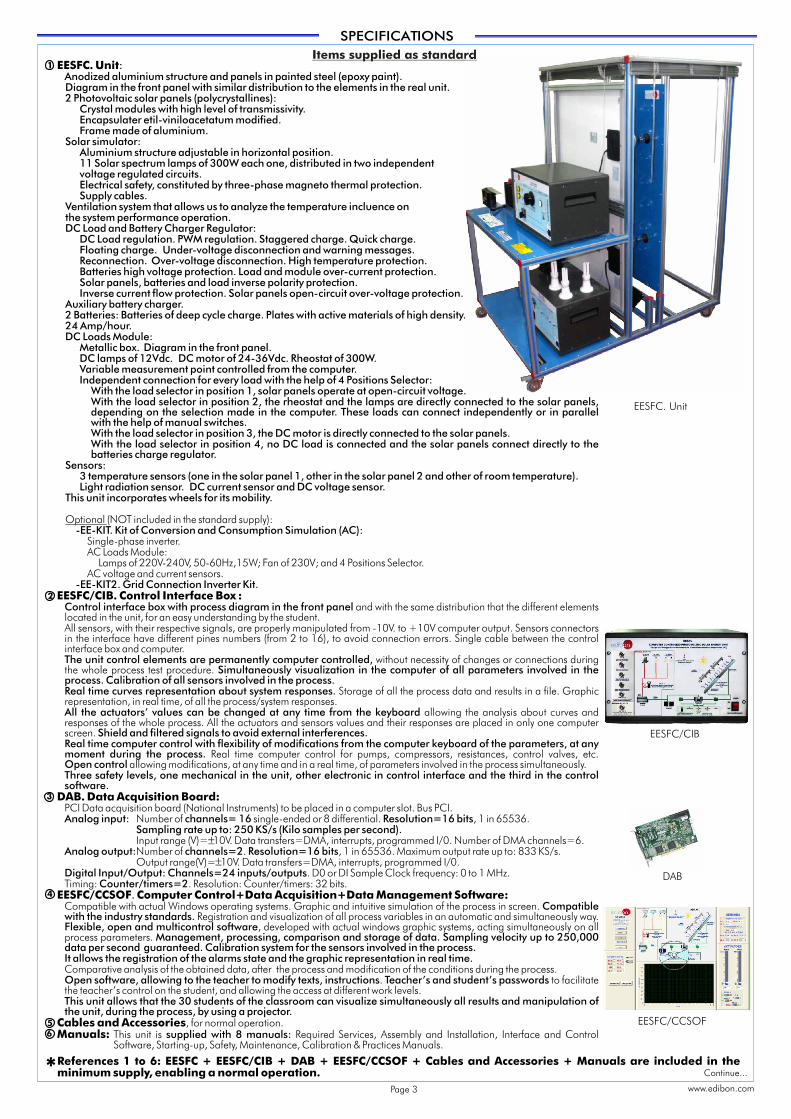
EESFC. Unit:Anodized aluminium structure and panels in painted steel (epoxy paint).Diagram in the front panel with similar distribution to the elements in the real unit.2 Photovoltaic solar panels (polycrystallines):
Crystal modules with high level of transmissivity.Encapsulater etil-viniloacetatum modified.Frame made of aluminium.
Solar simulator:Aluminium structure adjustable in horizontal position.11 Solar spectrum lamps of 300W each one, distributed in two independent voltage regulated circuits.Electrical safety, constituted by three-phase magneto thermal protection.Supply cables.
Ventilation system that allows us to analyze the temperature incluence on the system performance operation.DC Load and Battery Charger Regulator:
DC Load regulation. PWM regulation. Staggered charge. Quick charge.Floating charge. Under-voltage disconnection and warning messages. Reconnection. Over-voltage disconnection. High temperature protection.Batteries high voltage protection. Load and module over-current protection.Solar panels, batteries and load inverse polarity protection.Inverse current flow protection. Solar panels open-circuit over-voltage protection.
Auxiliary battery charger.2 Batteries:
DC Loads Module:Metallic box. Diagram in the front panel.DC lamps of 12Vdc. DC motor of 24-36Vdc. Rheostat of 300W.
Sensors:3 temperature sensors (one in the solar panel 1, other in the solar panel 2 and other of room temperature).Light radiation sensor. DC current sensor and DC voltage sensor.
This unit incorporates wheels for its mobility.
Optional (NOT included in the standard supply)::
Single-phase inverter.AC Loads Module:
Lamps of 220V-240V, 50-60Hz,15W; Fan of 230V; and 4 Positions Selector.AC voltage and current sensors.
EESFC/CIB. Control Interface Box :Control interface box with process diagram in the front panel and with the same distribution that the different elements located in the unit, for an easy understanding by the student.All sensors, with their respective signals, are properly manipulated from -10V. to +10V computer output. Sensors connectors in the interface have different pines numbers (from 2 to 16), to avoid connection errors. Single cable between the control interface box and computer.The unit control elements are permanently computer controlled, without necessity of changes or connections during the whole process test procedure. Simultaneously visualization in the computer of all parameters involved in the process. Calibration of all sensors involved in the process.Real time curves representation about system responses. Storage of all the process data and results in a file. Graphic representation, in real time, of all the process/system responses.All the actuators’ values can be changed at any time from the keyboard allowing the analysis about curves and responses of the whole process. All the actuators and sensors values and their responses are placed in only one computer screen. Shield and filtered signals to avoid external interferences.Real time computer control with flexibility of modifications from the computer keyboard of the parameters, at any moment during the process. Real time computer control for pumps, compressors, resistances, control valves, etc. Open control allowing modifications, at any time and in a real time, of parameters involved in the process simultaneously.Three safety levels, one mechanical in the unit, other electronic in control interface and the third in the controlsoftware.
DAB. Data Acquisition Board:PCI Data acquisition board (National Instruments) to be placed in a computer slot. Bus PCI.Analog input: Number of channels= 16 single-ended or 8 differential. Resolution=16 bits, 1 in 65536.
Sampling rate up to: 250 KS/s (Kilo samples per second).Input range (V)= 10V. Data transfers=DMA, interrupts, programmed I/0. Number of DMA channels=6.
Analog output:Number of channels=2. Resolution=16 bits, 1 in 65536. Maximum output rate up to: 833 KS/s.Output range(V)= 10V. Data transfers=DMA, interrupts, programmed I/0.
Digital Input/Output: Channels=24 inputs/outputs. D0 or DI Sample Clock frequency: 0 to 1 MHz.Timing: Counter/timers=2. Resolution: Counter/timers: 32 bits.
EESFC/CCSOF. Computer Control+Data Acquisition+Data Management Software:Compatible with actual Windows operating systems. Graphic and intuitive simulation of the process in screen. Compatiblewith the industry standards. Registration and visualization of all process variables in an automatic and simultaneously way.Flexible, open and multicontrol software, developed with actual windows graphic systems, acting simultaneously on all process parameters. Management, processing, comparison and storage of data. Sampling velocity up to 250,000 data per second guaranteed. Calibration system for the sensors involved in the process.It allows the registration of the alarms state and the graphic representation in real time. Comparative analysis of the obtained data, after the process and modification of the conditions during the process.Open software, allowing to the teacher to modify texts, instructions. Teacher’s and student’s passwords to facilitate the teacher’s control on the student, and allowing the access at different work levels.This unit allows that the 30 students of the classroom can visualize simultaneously all results and manipulation of the unit, during the process, by using a projector.
Cables and Accessories, for normal operation.Manuals: This unit is supplied with 8 manuals: Required Services, Assembly and Installation, Interface and Control
Software, Starting-up, Safety, Maintenance, Calibration & Practices Manuals.
Batteries of deep cycle charge. Plates with active materials of high density.24 Amp/hour.
Variable measurement point controlled from the computer.Independent connection for every load with the help of 4 Positions Selector:
With the load selector in position 1, solar panels operate at open-circuit voltage.With the load selector in position 2, the rheostat and the lamps are directly connected to the solar panels, depending on the selection made in the computer. These loads can connect independently or in parallel with the help of manual switches.With the load selector in position 3, the DC motor is directly connected to the solar panels.With the load selector in position 4, no DC load is connected and the solar panels connect directly to the batteries charge regulator.
-EE-KIT. Kit of Conversion and Consumption Simulation (AC)
-EE-KIT2. Grid Connection Inverter Kit.
SPECIFICATIONS
1
2
56
4
Items supplied as standard
3
Continue...
www.edibon.com
References 1 to 6: EESFC + EESFC/CIB + DAB + EESFC/CCSOF + Cables and Accessories + Manuals are included in the minimum supply, enabling a normal operation.*
±
±
Page 3
EESFC/CIB
EESFC/CCSOF
EESFC. Unit
DAB

SPECIFICATIONS (continuation)
Optional
www.edibon.com
� Single-phase i
Single-phase.
witch mode technology.
Start-up power of 200%.
Short-circuits protection.
High temperature protection.
Overcharge protection.
Operation state LED indicator.
Rear connection/disconnection switch.
� AC Loads Module:
nverter
25 kHz s
Independent connection for every load with the help of 4 PositionsSelector:
-With the load selector in position 1, the inverter operates without load.
-With the load selector in position 2, the fan motor is connected.
-With the load selector in position 3, one AC lamp is connected.
-With the load selector in position 4, two AC lamps are connected in parallel.
� AC Voltage and Current sensors.
� Grid Connection Inverter:
Input (DC):
Nominal power @ 25ºC: 535 W.
Maximum power @ 25ºC: 600 W.
PV power: 160-700 Wp.
MPP voltage: 40-125V DC.
Maximum voltage: 155V DC.
Nom. rated current: 8 A.
Output (AC):
Voltage: 85% 110% Un (195-253 V).
Nominal power: 525 W.
Maximum power/fuse: 2.25 A / 3.15 A.
Frequency: 49.5 50.5 Hz.
� Energy Generation Simulator.
:
Metallic box.
Diagram in the front panel.
Fan of 230V.
Lamps of 220V - 240V., 50-60 Hz., 15W.
Inverter used for the conversion and injection to the grid of the power generated by a simulated source of renewable energy. The simulated source is a simulator used to obtain a variable power to be injected to the grid.
The operation mode is displayed by means of a LED indicator at the front side of the housing.
It is equipped with extensive safety measures to ensure that it switches off immediately as soon as the AC plug is removed from the wall socket or the public grid fails in operation.
The inverter can be connected to a PC through RS232 communication to display some parameters such as voltage and current inputs, mains voltage and frequency, maximum AC power, Kwh, etc.
Inverter
EE-KIT. Kit of Conversion and Consumption Simulation (AC):
Continue...
Page 4
EE-KIT2. Grid Connection Inverter Kit:
~
~
AC Loads Module
AClamps
Fan
4 PositionsSelector

EESFC/CAL. Computer Aided Learning Software (Results Calculation and Analysis).
EESFC/FSS. Faults Simulation System:
7
Complementary items to the standard supply
Items available on request
8
99
10
PLC. Industrial Control using PLC (7 and 8): PLC-PI. PLC Module:
EESFC/PLC-SOF. PLC Control Software:For this particular unit, always included with PLC supply.
Circuit diagram in the front panel.Front panel:
Digital inputs(X) and Digital outputs (Y) block: 16 Digital inputs, activated by switches and 16 LEDs for confirmation (red). 14 Digital outputs (through SCSI connector) with 14 LEDs for message (green).
Analog inputs block: 16 Analog inputs (-10V. to + 10V.)( through SCSI connector). Analog outputs block: 4 Analog outputs (-10V. to + 10V) (through SCSI connector).Touch screen: High visibility and multiple functions. Display of a highly visible status. Recipe function. Bar graph function. Flow display function. Alarm list. Multi language function. True type fonts.
Back panel: Power supply connector. Fuse 2A. RS-232 connector to PC.Inside:
Power supply outputs: 24 Vdc, 12 Vdc, -12 Vdc, 12 Vdc variable.Panasonic PLC:
High-speed scan of 0.32 msec. for a basic instruction. Program capacity of 32 Ksteps, with a sufficient comment area. Free input AC voltage(100 to 240 V AC). DC input:16 (24 V DC). Relayoutput: 14 (250 V A AC/2 A). High-speed counter. Multi-point PID control.
Digital inputs/outputs and analog inputs/outputs Panasonic modules.Communication RS232 wire, to computer (PC).
PLC-PI
EESFC/FSS is a software application in which the instructor can define a faults sequence during the execution of the unit. The student, when executing the software, should identify this sequence.
Faults mode Access Screen
Once accessing, we have two possibilities: configure the faultssequence ("configure" button) or reset the previous sequence("reset" button).
Faults mode Main Screen
Faults Sequence Configuration
The software will ask for the first, second...until the sixth fault. To select the fault we will use the red ring called "faults". In this option, we will be able to repeat faults, that is to say,the same fault will be able to be included the times we want.
When selecting the faults the order of the sequence can be seen in the“Faults order" indicator, as shown in this image.
Faults mode active indicator (top left)
www.edibon.comPage 5
SPECIFICATIONS (continuation)

EDIBON Computer Control System
Software Main Screens
Main screen
Examples of Sensors Calibration screens
www.edibon.comPage 6
Note: ST= Temperature sensor. SRL= Radiation sensor. DC-1= DC current sensor. DC-2= DC voltage sensor. AC-1=AC current sensor. AC-2= AC voltage sensor.

POSSIBILITIES OF OTHER AVAILABLE EXPANSIONS
Some Practical Possibilities of the Unit:
1.- Determination of the typical parameters of the solar panels. 29.- Connection of loads to direct voltage.
2.- Study of the existing relation between generated power and power of Other possible practices:solar radiation. 30.- Sensors calibration.
3.- Study of the maximum performance of the solar panels. Practices to be done with the OPTIONAL KIT “EE-KIT”:4.- Study the influence of the temperature on the tension of circuit opened of 31.- Study of functionality of the photovoltaic system series/parallel with
the solar panels. connection of different loads and without support of the storage batteries.5.- Study of the behaviour of the solar panels connected in parallel. 32.- Study of functionality of the photovoltaic system series/paralell with 6.- Study of the behaviour of the solar panels connected in series. connection of different loads AC and with support of the storage batteries.
7.- Study of the behaviour of the system connected in parallel depending on 33.- Connection of loads to alternating voltage of 220 V.temperature. Practices to be done with the OPTIONAL KIT “EE-KIT2”:
8.- Lamps illumination profile study. 34.- Study of the grid utility inverter.9.- Efficiency experimental determination. Practices to be done by PLC Module (PLC-PI)+PLC Control Software:
10.- Influence of the angle of incidence on the temperature. 35.- Control of the EESFC unit process through the control interface box without 11.- Determination of the material that makes up the solar cell. computer.
12.- Determination of the p and n side of a solar cell. 36.- Visualization of all the sensors values used in the EESFC unit process.
13.- Determination of the first quadrant of the I-V curve, without illumination 37.- Calibration of all sensors included in the EESFC unit process.of the solar cell. 38.- Hand on of all the actuators involved in the EESFC unit process.
14.- Determination of the inverse current or the saturation current with regard 39.- Realization of different experiments, in automatic way, without having in to a solar cell without illumination. front the unit. (This experiment can be decided previously).
15.- Determination of the resistance in series and in parallel of a solar cell 40.- Simulation of outside actions, in the cases do not exist hardware elements without illumination. (Example: test of complementary tanks, complementary industrial
16.- Dependence of the voltage of open circuit ( V ) with the lumens. environment to the process to be studied, etc).oc
41.- PLC hardware general use and manipulation.17- Determination the characteristic parameters of a solar cell with illumination. 42.- PLC process application for the EESFC unit.
18.- Relation of the maximum power with the power input. 43.- PLC structure.19.- Determination of the parameters that define the quality of a solar cell. 44.- PLC inputs and outputs configuration.20.- Solar energy measurement. 45.- PLC configuration possibilities.21.- Measurement of the solar panel voltage in the vacuum. 46.- PLC program languages.22.- Determination of the cells disposition in a solar panel. 47.- PLC different programming standard languages.23.- Measurement of the maximum power for a solar panel with load. 48.- New configuration and development of new process.24.- Measurement of the solar panel voltage in vacuum with constant 49.- Hand on an established process.
illumination and different temperature.50.- To visualize and see the results and to make comparisons with the EESFC
25.- Study of V,I,W according to different loads. unit process.26.- Familiarization with the regulator parameters. 51.- Possibility of creating new process in relation with the EESFC unit.27.- Study of functionality of the photovoltaic system series/parallel with 52.- PLC Programming Exercises.
connection of different loads and without support of the storage batteries.53.- Own PLC applications in accordance with teacher and student
28.- Study of functionality of the photovoltaic system series/paralell with requirements.connection of different loads DC and with support of the storage batteries.
EXERCISES AND PRACTICAL POSSIBILITIES
SoftwareMini Scada-Net
Note: The Mini ESNsystem can be usedwith any EDIBON computer controlledunit.
30 StudentPost
LOCAL NET
OPEN CONTROL+
MULTICONTROL+
MULTISTUDENT POST
11 12
Computer ControlSoftware:Computer Control+Data Acquisition+Data Management
MultipostEDIBONMini Scada-Net System
Mini ESN.
1 UNIT=30 STUDENT can
work simultaneosly
Expansion 1: Expansion 2:
Control Interface
Box
Photovoltaic Solar Energy Unit (EESFC)
TeachingTechnique
usedMultipost EDIBON Scada-Net SystemESN.
30 StudentPost
Teacher’sCentral
Computer“SCADA”
COMPUTERCENTRAL
CENTRAL PLC
“n”Any otheradditionalcomputercontrolled
Unit
TeachingTechnique
used
Thermal Solar Energy Unit(EESTC)
Photovolatic Solar Energy Unit(EESFC)
“REAL TIME MULTICONTROL SYSTEMS”
OPEN CONTROL+
MULTICONTROL+
MULTI STUDENT POST
“ETDL” EDIBON TECHNICALDISTANCE LEARNING SYSTEM
30 students can workat the same time
Note: The ESN system can use any EDIBON computer controlled unit.
LOCAL NET
Option
Wind Energy Unit(EEEC)
30 StudentPost
www.edibon.comPage 7
PEM Fuel Cell Unit(EPCPEMC)
Teaching and ResearchBiodiesel Pilot Plant (BPPC)

DIMENSIONS & WEIGHTS
EESFC unit : -Dimensions: 2200 x 1200 x 2005 mm. approx.-Weight: 300 Kg. approx.
Control Interface Box: -Dimensions: 490 x 330 x 310 mm. approx.-Weight: 10 Kg. approx.
PLC Module (PLC-PI): -Dimensions: 490 x 330 x 310 mm. approx.-Weight: 30 Kg. approx.
REQUIRED SERVICES
-Electrical supply: three-phase, 400V, 50-60Hz, and minimum power 5000VA.
-Computer (PC).
OPTIONAL
- EE-KIT. Kit of Conversion and Consumption Simulation (AC)
- EE-KIT2. Grid Connection Inverter Kit
- PSA/PC.
- PSA/MC.
- PSA/AM.
:
Single-phase inverter.AC Loads Module:
Lamps of 220V-240V, 50-60Hz,15W; Fan of 230V; and 4 Positions Selector.AC voltage and current sensors.
:
Grid Connection Inverter.Energy Generation Simulator.
Polycrystalline photovoltaic solar panel. (2 units)
Monocrystalline solar panel. (2 units)
Amorphous solar panel. (2 units)
photovoltaic
photovoltaic
Complementary items to the standard supply
Minimum configuration for normal operation includes: PLC. Industrial Control using PLC (7 and 8):
Unit: EESFC. Photovoltaic Solar Energy Unit. PCL-PI.PLC Module.
EESFC/CIB.Control Interface Box. EESFC/PLC-SOF. PLC Control Software.
DAB.Data Acquisition Board. EESFC/CAL. Computer Aided Learning Software (Results Calculation and Analysis). (Available on request).EESFC/CCSOF. Computer Control + Data Acquisition + Data
Management Software. EESFC/FSS. Faults Simulation System.
Cables and Accessories, for normal operation.
Manuals. Expansions
Mini ESN. Multipost EDIBON Mini Scada-Net System.
* IMPORTANT: Under EESFC we always supply all the ESN. Multipost EDIBON Scada-Net System.elements for immediate running as 1, 2, 3, 4, 5 and 6.
ORDER INFORMATION
1
2
3
4
5
6
12
11
10
9
8
7
Items supplied as standard
*Specifications subject to change without previous notice, due to the convenience of improvements of the product.
Offered in this catalogue:
- EESFC. .
Offered in other catalogue:
- EESFB. .
Computer Controlled Photovoltaic Solar Energy Unit
Photovoltaic Solar Energy Unit
AVAILABLE VERSIONS