Embed Size (px)
Citation preview
Pergamon 00457949(94)EO131-K
Computers & strucrures Vol. s2. No. 5. pp. 879493, 1994 Copyright 0 1994 Elsevier Science Ltd
Printed in Great Britain. All rights reserved cQ45-7949/94 57.00 + 0.00
COMPUTER MODELLING OF AN EXTENDED END-PLATE BOLTED CONNECTION
M. R. BAHAARI and A. N. SHERBOURNE
Department of Civil Engineering, University of Waterloo, Waterloo, Ontario, Canada N2L 3Gl
(Received 5 April 1993)
Abstract-A methodology, based on finite element modelling, is studied to develop analytically the moment-rotation relationship for a steel bolted end-plate connection. ANSYS, a large-scale general- purpose finite element code is selected for equivalent two-dimensional (2-D) analysis. The end-plate, beam and column flanges, web and bolt shanks in the tension region are represented as plane-stress elements with their width equal to their thickness measured perpendicular to the web. Interface elements are used to model the boundary between column flange and rear of end-plate that may make or break contact. Based on deformation and stress contours of a 2-D model the contribution of beam web to the behaviour is discussed from which two types of end-plate deformation can be identified. The methodology is demonstrated for an extended end-plate connection and the results are compared against experimental data to verify the feasibility of the modelling and associated computer analyses.
INTRODUaION
In conventional analysis and design of steel frame building structures, the beam-to-column connection is presented as an idealized joint, i.e. fully rigid, implying complete rotational continuity, and/or pinned, implying no moment transfer. However, these two commonly used models correspond to the two extreme cases of true joint behaviour and their validities are not corroborated by experiments. More- over, all steel frames can be classified under the heading of semi-rigid construction, while recognizing simple and continuous construction as extreme cases [l]. The prediction of joint rotational behaviour is a prerequisite for performing any sort of frame analysis that seeks to include partial rigidity of connections. The behaviour of the connection is often nonlinear even when the components remain elastic.
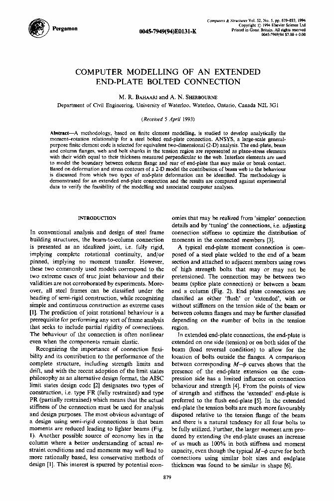
Recognizing the importance of connection flexi- bility and its contribution to the performance of the complete structure, including strength limits and drift, and with the recent adoption of the limit states philosophy as an alternative design format, the AISC limit states design code [2] designates two types of construction, i.e. type FR (fully restrained) and type PR (partially restrained) which means that the actual stiffness of the connection must be used for analysis and design purposes. The most obvious advantage of a design using semi-rigid connections is that beam moments are reduced leading to lighter beams (Fig. 1). Another possible source of economy lies in the column where a better understanding of actual re- straint conditions and end moments may well lead to more rationally based, less conservative methods of design [l]. This interest is spurred by potential econ-
omies that may be realized from ‘simpler’ connection details and by ‘tuning’ the connections, i.e. adjusting connection stiffness to optimize the distribution of moments in the connected members [3].
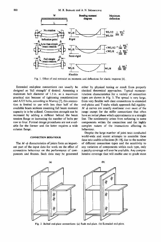
A typical end-plate moment connection is com- posed of a steel plate welded to the end of a beam section and attached to adjacent members using rows of high strength bolts that may or may not be pretensioned. The connection may be between two beams (splice plate connection) or between a beam and a column (Fig. 2). End plate connections are classified as either ‘flush’ or ‘extended’, with or without stiffeners on the tension side of the beam or between column flanges and may be further classified depending on the number of bolts in the tension region.
In extended end-plate connections, the end-plate is extended on one side (tension) or on both sides of the beam (load reversal condition) to allow for the location of bolts outside the flanges. A comparison between corresponding M-4 curves shows that the presence of the end-plate extension on the com- pression side has a limited influence on connection behaviour and strength [4]. From the points of view of strength and stiffness the ‘extended’ end-plate is preferred to the flush end-plate [5]. In the extended end-plate the tension bolts are much more favourably disposed relative to the tension flange of the beam and there is a natural tendency for all four bolts to be fully utilized. Further, the larger moment arm pro- duced by extending the end-plate causes an increase of as much as 100% in both stiffness and moment capacity, even though the typical M-4 curve for both connections using similar bolt sizes and endplate thickness was found to be similar in shape [6].
879
880 M. R. BAHAARI and A. N. SHERLIOURNE
Maximum de&&on
Rigid
WE/8 <wL/12 ‘3x EI
I u!3 1 wL.3
<WE/8 5 WL3 <3X iZ-
Semi-rigid
,t;,, u lWLI8 j&g
Flexible
Fig. 1. Effect of end restraint on moments and deflections for elastic response [I].
Extended end-plate connections can usually be designed as ‘full strength’ if desired. Assuming a maximum bolt diameter of 1.5 in. as a maximum practical size because of tightening considerations and A325 bolts, according to Murray [7], this connec- tion is limited to use with less than half of the available beam sections assuming full beam moment capacity is to be utilized. Connection strength can be increased by adding a stiffener behind the beam tension flange or increasing the number of bolts per row to four. Formal design procedures are not avail- able for the former and the latter requires a wide column flange.
CONNECTION BEHAVIOUR
The M-4 characteristics of joints form an import- ant part of the input data for work on the effect of connection behaviour on the performance of com- ponents and frames. Such data may be generated
(a)
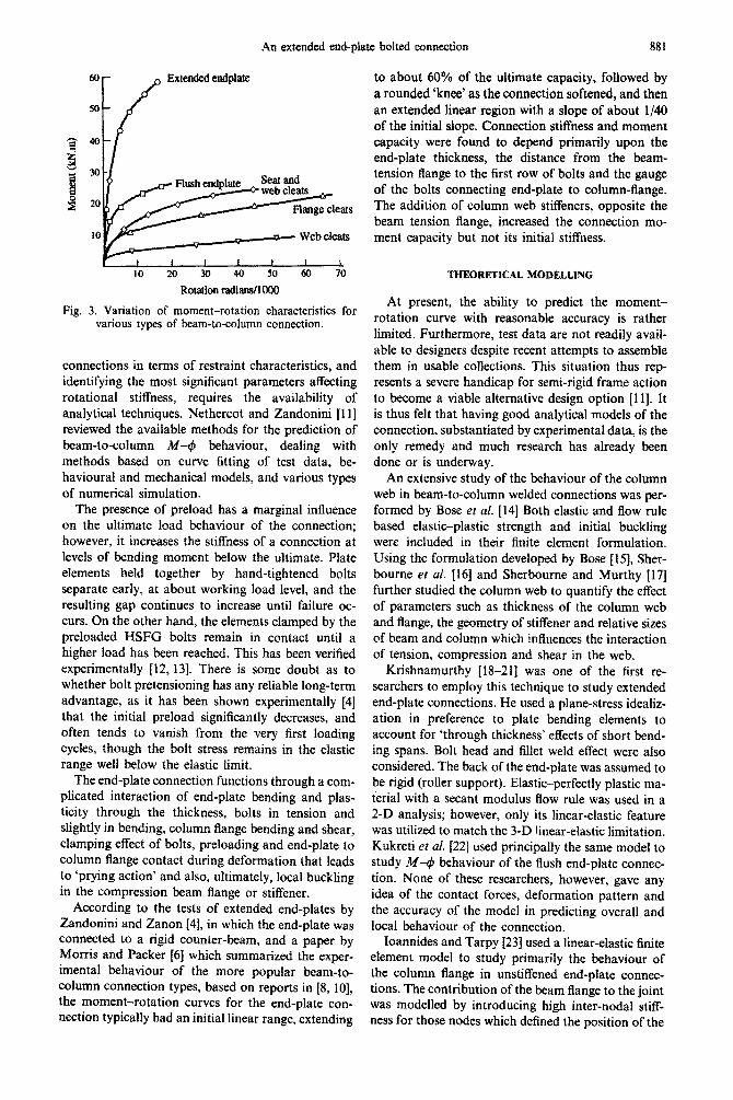
either by physical testing or result from properly checked theoretical approaches. Typical moment- rotation characteristics for a variety of connection types are shown in Fig. 3. The spread is very large, from very flexible web cleat connections to extended end-plates and T-stubs which approach full rigidity. M-4 curves are usually nonlinear over most of the range except for the stiffer connections that often have an initial phase which approximates to a straight line. The nonlinearity arises from softening in some components within the connection and the highly complex nature of the interactions affecting its behaviour.
Despite the large number of joint tests conducted world-wide and recent attempts to assemble these data into usable collections [8-lo], due to the number of different connection types and the sensitivity to any variation of components within each type, only a patchy coverage will ever be available. Any compre- hensive coverage that will enable one to grade most
W
Fig. 2. Bolted end-plate connections: (a) flush end-plate. (b) Extended end-plate.
An extended end-plate bolted connection 881
Fig.
60
M
40
30
20
10
10 20 30 40 50 70
Rotation radians/l000
3. Variation of moment-rotation characteristics for various types of beam-to-column connection.
connections in terms of restraint characteristics, and identifying the most significant parameters affecting rotational stiffness, requires the availability of analytical techniques. Nethercot and Zandonini 11 I] reviewed the available methods for the prediction of ~~-to-column iM-4, behaviour, dealing with methods based on curve fitting of test data, be- havioural and mechanical models, and various types of numerical simulation.
The presence of preload has a marginal influence on the ultimate load behaviour of the connection; however, it increases the stiffness of a connection at levels of bending moment below the ultimate. Plate elements held together by hand-tightened bolts separate early, at about working load level, and the resulting gap continues to increase until failure oc- curs. On the other hand, the elements clamped by the preloaded HSFG bolts remain in contact until a higher load has been reached. This has been verified experimentally [12,13]. There is some doubt as to whether bolt pretensioning has any reliable long-term advantage, as it has been shown experimentally [4] that the initial preload significantly decreases, and often tends to vanish from the very first loading cycles, though the bolt stress remains in the elastic range well below the elastic Iimit.
The end-plate connection functions through a com- plicated interaction of end-plate bending and plas- ticity through the thickness, bolts in tension and slightly in bending, column flange bending and shear, clamping effect of bolts, preloading and end-plate to column flange contact during deformation that leads to ‘prying action’ and also, ultimately, local buckling in the compression beam flange or stiffener.
According to the tests of extended end-plates by Zandonini and Zanon [4], in which the end-plate was connected to a rigid counter-beam, and a paper by Morris and Packer [6] which summarized the exper- imental behaviour of the more popular beam-to- column connection types, based on reports in [8, lo], the moment-rotation curves for the end-plate con- nection typically had an initial linear range, extending
to about 60% of the ultimate capacity, followed by a rounded ‘knee’ as the connection softened, and then an extended linear region with a slope of about l/40 of the initial slope. Connection stiffness and moment capacity were found to depend primarily upon the end-plate thickness, the distance from the beam- tension flange to the first row of bolts and the gauge of the bolts connecting end-plate to column-flange. The addition of column web stiffeners, opposite the beam tension flange, increased the connection mo- ment capacity but not its initial stiffness.
At present, the ability to predict the moment- rotation curve with reasonable accuracy is rather limited. Furthermore, test data are not readily avail- able to designers despite recent attempts to assemble them in usable collections. This situation thus rep- resents a severe handicap for semi-rigid frame action to become a viable alternative design option [1 11. It is thus felt that having good analytical models of the connection, substantiated by experimental data, is the only remedy and much research has already been done or is underway.
An extensive study of the behaviour of the column web in beam-to-column welded connections was per- formed by Bose et al. [14] Both elastic and flow rule based elastic-plastic strength and initial buckling were included in their finite element fo~ulation. Using the formulation developed by Bose [l5], Sher- bourne et al. [ 161 and Sherbourne and Murthy 1171 further studied the column web to quantify the effect of parameters such as thickness of the column web and flange, the geometry of stiffener and relative sizes of beam and column which influences the interaction of tension, compression and shear in the web.
Krishnamurthy [18-211 was one of the first re- searchers to employ this technique to study extended end-plate connections. He used a plane-stress idealiz- ation in preference to plate bending elements to account for ‘through thickness’ effects of short bend- ing spans. Bolt head and fillet weld effect were also considered. The back of the end-plate was assumed to be rigid (roller support). Elastic-perfectly plastic ma- terial with a secant modulus flow rule was used in a 2-D analysis; however, only its linear-elastic feature was utilized to match the 3-D linear-elastic limitation. Kukreti et al. [22] used principally the same model to study A&-d behaviour of the flush end-plate connec- tion. None of these researchers, however, gave any idea of the contact forces, deformation pattern and the accuracy of the model in predicting overall and local behaviour of the connection.
Ioannides and Tarpy 1231 used a linear-elastic finite element model to study primarily the behaviour of the column flange in unstiffened end-plate connec- tions. The contribution of the beam flange to the joint was modelled by introducing high inter-nodal stiff- ness for those nodes which defined the position of the

882 M. R. BAHAARI and A. N. SHERBWRNE
beam flanges. The bolt head and preload could not be modelled due to using only plate bending elements in the model.
Jenkins et al. [24] attempted to assess the behaviour of stiffened connections by summing each contribu- tion to the joint moment and rotation capacity using separate analyses for end-plate bending, column flange bending with transverse tension/compression stiffeners, and bolt deformation relationships. The transverse plate deformations at the bolt positions were then transformed into a rotation 4, about the compression flange of the beam. Weld effects were considered by increasing the material yield stress. A major source of approximation in this procedure was that each contribution to the rotation, 4, was ob- tained independently; the total connection rotation, 4, at a particular value of moment, iw, was then calculated as
# =#,+cp,+fptl. (1)
Lee [25] used the NONSAP program to study end-plate connections including extended, flush and splice types. Lee modelled the bolts as four truss elements, two serving for tensile force and the other two for shear transfer. In the contact area some truss elements, which were very soft in tension and very stiff in compression, acted as being easily separated but resisted compression.
ANALYTICAL MODELLINC
The problem in the case of end-plate connations is basically one of biaxial plate bending 1261. In most cases the relative dimensions of the joint makes it a ‘thick’ plate problem in which the forces disperse through the thickness.
Methods using empirical and nondimensional curve fitting techniques have been used but, as yet, no method appears to exist for the theoretical prediction of complete moment-rotation behaviour taking into account material nonlinearity, strain-hardening, full 3-D behaviour (including lateral shear, lateral bend- ing and twisting which are three out-of-plane degrees of freedom) and column side-effects. Among avail- able techniques, and because of the advent of the computer, finite element analysis is very promising and can significantly reduce the number of full scale tests normally required to establish behaviour.
FINITE ELEMENT APPROACH
A numerical simulation appears to be the oniy means for studying the complex interaction between member and connection components. Some reasons for this are:
1. Experimental studies, although of paramount importance, provide rather limited information on displa~ments and forces.
2. Local effects either cannot be measured at all or cannot be measured with the necessary accuracy, e.g. local bolt deformations in threaded parts, prying forces and their distribution with load, contact forces
between the bolt and the connection components. 3. Significant numbers of geometrical and mechan-
ical parameters influence join behaviour. 4. Advances in computer and computational
methods. 5. A satisfactory approach to the comprehensive
analysis of connection behaviour must include elastic and plastic behaviour.
Finite element, elastic-plastic analysis produces a continuous relationship between applied bending mo- ment and resuiting rotation up to the ultimate limit state [24]. Within this method the complex behaviour of end-plate connections which include bolt perform- ance and matters such as forces and contact zones, the effect of stiffeners and material nonlinearity, can be modelled.
End-plate connections have particular aspects that need to be considered in the complete model. These connections are made up of a number of small components and the bending spans between fasteners and member parts are of the same order of magnitude as the end-plate thickness. In loads near the ultimate, strain-hardening is activated and a complicated inter- action of shear and tension or compression takes place. The contact region between the end-plate and column flange varies with the load level and is very sensitive to relative sizes of bolts, their arrangement, end-plate and column flange thickness. Under large applied loads and following considerable defor- mation of the end-plate, bolt slip might occur de- pending on the bolt to hole clearance and its shank undergoes bending.
The problem is obviously 3-D in nature. However, a 3-D finite element analysis is more complicated than 2-D and much more demanding in time and effort of input preparation and output evaluation, and even more importantly, in time and machine requirements for computation. To develop prediction equations characterizing the behaviour of the connection, it was therefore decided to conduct 2-D finite element analysis on a plane-stress model taken parallel to the plane passing through the mid-thickness of the webs. Since transverse defo~ation and stresses and their variation cannot be represented by a 2-D model (Fig. 4), a parallel analysis on a model isolating the elements on the plane passing through the bolt line of the connection is considered as well.
A typical configuration of the 2-D finite element model used in the present study is shown in Fig. 5. Since the model is, in fact one of plane stress taken parallel to the plane passing through the mid-thick- ness of the webs of beam and column, it is called a web-line model in this study. A length of beam equal to its depth is chosen as adequate for inclusion in the anatysis domain. The end-plate, beam and column flanges, web and bolt shanks in the tension region are represented as plane-stress elements with their width equal to their thickness measured perpendicular to the web. The bolts in the compression region are modelled by three tension-only members.

An extended end-plate bolted connection 883
(a) (b) Fig. 4. Deformation pattern of plate for: (a) 2-D. (b) 3-D
model [ 181.
FINITE ELEMENT MODELLING
The bolts near the tension flange are simulated by modelling the bolt shanks as separate elements, con- nected at one end to the end-plate nodes at the plate
j?JIF-10 in the ANSYS library of elements.
(a) X-Section
surface and to the column flange nodes at the other end. The bolt area in a row is assumed to be uniformly spread across part of the width (as a rectangle) as shown in Fig. 5(a). The height of the equivalent rectangular bolt area is taken to be DB = (~~~/~)1~2, in which A, is the effective area of the bolt given by standard codes. Width of the equivalent rectangular area is BB = A,,/DB. The bolts near the compression flange are simulated by three tension-only elements.? One fourth of the effec- tive area is carried by each of the top and bottom elements and the remaining one half by the middle one.
For any accurate prediction of stresses and dis- placements, especially in the tension region of the connection, interaction of the end-plate and the column flange must be considered. The column flange to end-plate interaction is a complex problem in that the interface conditions between the two bodies vary depending on the level of interaction and loading. Interface elements are used to model the interface between these two surfaces that may make or break contact.
When modelled with finite elements, the two sur- faces know nothing about each other since no math- ematical connection (stiffness) exists between the surfaces. If the upper surface displaces downward due to a force P, it will ‘move through’ the lower surface as if it were not there (Fig. 6a). Attaching a spring of stiffness k to node L of the lower surface as shown in Fig. 6(b), will only carry load when the gap closes in compression. Therefore, when the upper surface ‘con- tacts’ the lower one, a spring force develops to prevent the upper surface from moving through the
(b) Elevation (c) Loading Fig. 5. Proposed finite element mesh configuration. (a) Cross-Section. (b) Elevation. (c) Bi-linear pressure
loading.

884 M. R. BAHAARI and A. N. SHEIUKJIJRNE
stationary ’ (a)
upper SIllface moves thraugh lower surface
T k
IL
(d
T I*
t f P-kA
(4 Fig. 6. Interface element mechanism. (a) Two separate surfaces. (b) Overlapping between the two surfaces. (c) Spring attachment. (d) Spring (interface) element activated
1271.
lower one. Equilibrium will be achieved where /CA = P. The amount of ‘pass through’, A, will there- fore depend on the spring stiffness k. Thus, STIF-12 interface elements are used to define contact between the elements of the back of the end-plate and the counterpart nodes along the outer surface of the column flange. Only the corner nodes of elements are connected.
Real surfaces have zero ‘material overlap’ which would result if k + 00. However, using a very high stiffness causes numerical problems in the equation solver and convergence difficulties in problems with multiple inter-surface elements. Practically, a value of k is required that will produce ‘acceptably small’ amounts of material overlap. According to the AN- SYS manual [27,28] this amount should be one or two orders of magnitude smaller than the expected displacements of the structure which, in turn, means that the inter-surface stiffness should be one or two orders of magnitude larger than the surrounding structural stiffness. Since the bolts are connected to end-plate and column flange within their transverse span, which cannot be accounted for in 2-D where all
tin practice it is recommended to use interface stiffness between 175 and 17,500 kN/mm.
the components including bolts are concentrated in the web-line, it is reasonable to restrict the material overlap to only a one-half order less than the main displacements of the structure. Within this limit, the mean stiffness of k = 175 kN/mm is selected for use in this ana1ysis.t No friction is considered in the contact zone and, initially, the interfaces are assumed to be closed with a displacement interference of 0.001 mm.
MATERIAL PROPERTIES
TO model the nonlinear material behaviour, the stress-strain relationship for the elements of the end-plate, beam and column webs and flanges is usually taken to be elastic-perfectly plastic, i.e. no strain hardening is considered. In structural elements, such as beams and columns this is acceptable since strain hardening is paired with excessive yielding in large areas and a large deflection criterion governs the ultimate strength design. In end-plate connections, however, excessive strain is mostly local and, besides, considerable shear stresses occur in the region be- tween the top bolts and the beam tension flange which necessitates considering strain hardening. In this study a minimum of 5% of the initial modulus of elasticity is defined as a tangential stiffness after the yield point is reached (Fig. 7a). For bolt material, a trilinear stress-strain curve is used, as shown in Fig. 7(b), in which the initial work hardening effect is considered to be 10% of the initial modulus of elasticity; after 35, the material stiffness becomes 5% of the initial value. These are typical stress-strain curves for soft steel and bolt material; the exact values can be found by related uniaxial tests. The combining of stresses at a point must be considered when determining the yield point. Many theories have been advanced to predict when a material will begin to yield under a multiaxial stress state. Typi- cally these theories, referred to as yield criteria, attempt to calculate a single-valued equivalent stress based on the combined stresses at the point. The latter can then be related to the uniaxial stress-strain curve. The von Mises yield criterion, which is most commonly applicable to initially isotropic engin- eering materials, is used to predict the onset of yielding. The equivalent stress is defined as
uCq = JOS[(o, - a# + (62 - oJ2 + (03 - 61 )*I. (2)
In 2-D analysis the equivalent stress reduces to
ffeq = a:+o;- 0102. (3)
The yield criterion serves only to predict when yield- ing will begin. Behaviour upon further yielding is predicted by the ‘flow rule’ and ‘hardening law’. The associative flow rule for the von Mises yield criterion, i.e. the Prandtl-Reuss flow equations, is used along with kinematic hardening of the bolt shank to model the Bauschinger effect by assuming that the yield

An extended end-plate bolted connection 885
400 (a)
360
320 1
Strain (0.001 &mm)
stmin (0.001 nlol/mm)
Fig. 7. (a) Stress-strain curve for beam, column and end- plate (b) Trilinear stress-strain curve for bolt shank.
surface only translates in the direction of yielding and does not grow in size.
LOAD AND DISPLACEMENT BOUNDARY CONDITIONS
There are two types of nonlinearity in the end-plate bolted connections: material nonlinearity and non- linear elements in the contact region. The response of the structure is thus path-dependent or nonconserva- tive. This requires that, in addition to multiple iter- ations per load step for convergence, the loads be applied slowly, in increments, to characterize the actual load history. Therefore, the load history needs to be discretized into a number of load steps with convergence iterations done in each load step. In
tFour-node elements are labelled as STIF-42 and eight- node elements are labelled as STIF-82 in the ANSYS library of elements.
practice, the rule of thumb for load increment size is to apply additional load (force or displacement) such that the corresponding additional plastic strain does not exceed the order of magnitude of the elastic strain.
In the present model, depending on the thickness
of the end-plate, the load which will create maximum stresses near the yield point is applied for which one or two iterations may suffice to converge. Succeeding load steps are defined with 10% of the yield stress as the load increment. Pure bending load is considered by applying bilinear pressure loading, in which the pressure along the beam flange thickness is uniform, but is linearly distributed along the web as shown in Fig. S(c).
Symmetric displacement boundary conditions are defined for the nodes along the centre line of the column web. Since the slope in the mid-span of the test specimen is zero, these nodes are constrained along both axes X and Y, thus modelling the speci- men as a cantilever beam. All other nodes have two translational degrees of freedom in general (Fig. 5b).
Convergence studies form an integral part of every analysis from which quantitative conclusions are intended to be extracted. Three progressively finer meshes were used in two groups using four- and eight-node? isoparametric solid elements to analyse typical connections. Variations of maximum dis- placement and stress were compared in each group separately and the second finest mesh of each group was selected provided the difference between the results of the finest two meshes was within 5-7%. As the best compromise between accuracy and economy of analysis, the eight-node element mesh with 341 elements, 1070 nodes, 1988 active degree of freedom was selected.
VERIFICATION
An example is selected from the ABAQUS (version 4-8) manual [29] to show the exactness and/or per- formance of the ANSYS plane-stress elements used in the proposed model. This example is intended to verify the coding of a standard rate-independent plasticity theory for metals and to assess the accuracy of the integration of the plasticity equations. Inte- gration of elastic-plastic material models is a poten- tial source of error in numerical structural analysis [30,31]. Usually the error is most severe when kin- ematic hardening is used in plane stress with non- proportional stressing.
Figure 8(a) shows the geometry and material model for this case. The geometric model is a single eight- node isoparametric (STIF-82) element. Two edges have simple support. The load history is shown in Fig. 8(b) and is prescribed through the ‘PSF’ option in ANSYS. The load distribution is a uniform, direct stress on the element edge. Since the strain should be uniform, the edge nodes are constrained via ‘CP’ (to define a set of coupled degrees of freedom) to move

886 M. R. BAHAARI and A. N. SHERBOURNE
These nodes constrained to have the same y-displacement
-I-
0.0254 m (1.0 in)
L
These nodes constrained to have the same x-displacement
(kinematic hardening)
. Elastic modulus:
0 1 I 11 15 18 23
Load step number
Fig. 8. An example to evaluate ANSYS for plasticity solution.
together in the direction normal to the edge. Then the the number of iterations necessary to converge is total load on the edge is simply given on one of the slightly larger, particularly for unloading toward a edge nodes. very small stress.
The exact solution for this problem has been developed by Chern in a Foster Wheeler report [32] and has been reported in the ABAQUS user’s manual [29] for comparison. The plastic strains are the basic solution in this case since the stress is prescribed. The results are summarized in Table 1. The ANSYS results agree to almost all digits printed with the exact solution. This level of agreement in both ABAQUS and ANSYS is attained because the solution conver- gence criterion, CNVR, was set to a tight tolerance of 0.001. The table also records the number of iterations required to achieve equilibrium to the prescribed tolerance. In comparison with ABAQUS,
RESULTS
Finite element analysis has been used to determine the complete moment-rotation relationship for cer- tain extended end-plate connections so that direct comparison with experimental results is possible. Jenkins et al.‘s [24] test results are used for this purpose. In both the experimental and analytical data, the rotation is calculated by measuring the horizontal displacement of the beam tension flange behind the end-plate and dividing by the effective beam depth. The beam and column used in the test

An extended end-plate bolted connection
Table 1. Comparison of results for plasticity of plane-stress element
Number of iterations c p’ x Load step a,t No. ABAQUS ANSYS (lb/in*) ABAQUS ANSYS Exact
1 1 1 10,000 0.0 0.0 0.0 2 3 4 15,000 0.500 0.500 0.500 3 3 4 20,000 1.000 1.000 1.000 4 3 4 25,000 1.500 1.500 1.500 5 1 1 12,550 1.500 1.500 1.500 6 3 6 100 1.010 1.010 1.010 I 1 2 15,050 1.010 1.010 1.010 8 3 4 30,000 2.000 2.000 N/A 9 1 2 15,050 2.000 2.000 N/A
10 3 6 100 1.010 0.990 1.010
887
tprescribed stress in the X-direction.
connection was a 305 x 165 x 54 (UB) (equivalent to W310 x 52 kg/m) and 254 x 254 x 132 UC (equival- ent to 250 x 131 kg/m), respectively. The bolts used were M20 grade 8.8 which compares with A325 20mm bolt. End-plate thickness varied from 12 to 25 mm. Only hand-tight bolt tests under pure bending were compared at this time. Column web stiffeners were used at the beam flange locations. The material properties used were as follows:
Young’s modulus of elasticity 205,000 MPa Yield stress for beam-column elements 240 MPa Yield stress for bolt shank 620 MPa Strain hardening for bolt shank 10% Strain hardening for other components 5% Poisson’s ratio 0.3.
The moment-rotation curves for the experimental versus finite element analysis results of the web-line model are shown in Fig. 9. The initial stiffness of the predicted curves is the same as the experimental results. However, the model is stiffer than the exper- imental results at loads greater than 3&50% of ultimate, especially for a thin end-plate connection. In the 2-D model, displacements are assumed to be
4
*
0
*
* Teat data (12 mm) l Web-line (12 mm) o Test data (15 mm) l web-line (15mm) 0 Test data (20 mm) o Web-line (2Omm) q Test data (25 mm) I web-line (25mm)
O* 5 I 10 I 15 I 20 I 25 I 30 I 35 I 40 I
Rotation (10e3) Fig. 9. Comparison of results for WEB-LINE model and
experiment.
distributed uniformly along the third dimension and no transverse stress effect can be taken into account. Besides, the bolts are positioned along the beam and column web line, contrary to the actual position in which they are acting on the column flange and transverse span of the end-plate. In other words, the column and beam web effects are overestimated in the 2-D model.
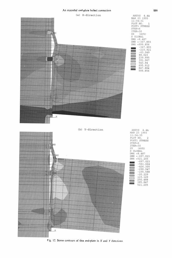
The displacement patterns of thin and thick end- plate, i.e. 12 and 25 mm, are shown in Figs 10 and 11, respectively. In the thin end-plate connection, the deformation at the back of the end-plate clearly consists of two separate sagging spans and the bolt under the tension flange is acting like a rigid support. Therefore, there is a two-span deformation pattern for which the web effect becomes a dominant par- ameter. However, for thick end-plate deformations, the back of the end-plate along the beam depth is almost linear starting from a maximum separation at the tension flange level and vanishing somewhere around the bolt in the compression side. There is a thus rigid-body type deformation along the beam web and the web effect is not as important as for the thin end-plate. Stress contours for the above connections confirm this observation. Again, for the thin end- plate, greater stresses are developed at the beam mid-depth and also at the beam to end-plate attach- ment point (Fig. 12a, b). However, the stresses for the thick end-plate are mainly in the bolts and tension flange to end-plate joint (Fig. 13a, b).
In order to evaluate closely the web effect, two adjusted cases are studied: (i) WEB-LESS: the orig- inal model without web elements of beam and column but with the same force (increased stress) and (ii) BOLT-LINE: the original model in the plane passing through the bolt-line for which one-half of the flange width under the same stress (decreased moment) is studied.
The first model is intended to clarify the effect of the web on the overall behaviour of the connection and is referred to as the web-less model in the study. Certainly, to compensate for the absence of the linear pressure loading on the web, the stress on the flanges has to be increased by approximately 15% to preserve the same moment. Defining the half-width of the

888 M. R.BAHAAR~ and A.N.SHERBOURNE
ANSYS 4.473 MAR 23 1993 11:34:42 PLOT NO. 3 POST1 STRESS STEP=6 ITER=jD UX D GLOBAL DMX =8.481 SMN =-1.205 SMX =5.826
Fig. 10. Deformation pattern of thin end-plate.
ANSYS 4.4A MAR 23 1993 12:25:03 PLOT NO. 1 POST1 STRESS STEP=1 ITER=30 UX D GLOBAL mix =6.49 SKN E-2.116 SMX =a.33
XI :y
-0.683985 0.032264 0.748514 1.465 2.181 2.897
Fig. I I. Deformation pattern of thick end-plate.
An extended end-plate bolted connection
(a) X-direction
(b) Y-direction
889
ANSYS 4.4A MAR 23 1993 11:34:31 PLOT NO. 1 POST1 STRESS STEP=6 ITERz30 sx (AK) S GLOEAL DMX =8.487 SMN =-367.893 SMX =999.856
.tiSYS 4.4A MAR 23 1993 11:34:35 PLOT NO. 2 POST1 STRESS STEP=6 ITER=30 S-Y (AVG) S GLOBAL DMX :P.487 SMN =-697.023 SMX ~521.205
Fig. 12. Stress contours of thin end-plate in X and Y directions

M.R. BAHAARI and A.N. SHERBOURNE
(a) X-direction
(b) Y-direction
ANSYS 4.4A MAR 23 1993 12:25:08 PLOT NO. 2 POST1 STRESS STEP=1 ITER=30 SX (AVG) S GLOBAL DMX =6.49 SMN =-401.346 SMX =923.182
ANSYS 4.4A MAR 23 1993 12:25:10 PLOT NO. 3 POST1 STRESS STEP=1 ITERx30 SY (AVG) S GLOBAL DMX =6.49 SMN =-360.358 SMX =369.227
Fig. 13. Stress contours of thick end-plate in X and Y directions.

An extended end-plate bolted connation 891
280
240
F
* Web-less . RolMle 0 Web-line * Test
I I I I I I I 0 5 10 I5 20 25 30 35 40
Rotation (1@3)
Fig. 14. Extended end-plate connection (12 mm).
components with only one bolt in each row, the second model is intended to approximate the bolt-line behaviour as an isolated portion from the remaining parts of the connection. Therefore, the stresses are kept the same as the original resulting in a smaller value of equivalent moment. This model is called the bolt-line model in this study.
Both of the above mentioned models are analysed for end-plate thicknesses of 12, 15, 18,20,22,25 and 30 mm and are compared with the original model in Figs 14-20. The difference between the web-less and original model is considerable for 12-18 mm plates and gradually vanishes in the range 20-30 mm. This difference, which can be attributed to the web effect, becomes clear exactly at the same point as the original model deviates from the test results {Fig. 9). However, the initial slope of both models and tests remain similar.
‘ii g ‘60 ‘i! # 120
s
80 * A a
40 *
.*
Web-less Bolt-line Web-line TestlSmm
I I I I I I J 0 5 10 15 20 25 30 35 40
Rotation ( 1tY3)
Fig. 15. Extended end-plate connection (15 mm).
* A
cl
Web-less Bolt-line Web-Iii
I d 5 I 10 I 15 I 20 I 25 I 30 I 35 I 40 I
Rotation ( 10-3)
Fig. 16. Extended end-plate connection (18 mm).
The situation in the bolt-line model is relatively better and, in spite of more flexibility in the plasticity level for thin end-plates, the difference, even in this range, becomes negligible for thicknesses between 20 and 30 mm. In fact, this model correlates with test data better than the original model. Therefore, for any extended end-plate connection, both models are run; if the difference between them is relatively small, the connection is classified as a ‘thick’ end-pIate for which the beam web effect is not mandatory and the ‘bolt-line’ model is used. However, a connection in which this difference is considerable is classified as ‘thin’, the web effect is crucial to the analysis and the original model is used. Since the original model overestimates the web effect and is stiffer than the tests, some reduction should be applied to the stiff- ness of the beam web. Some researchers have used a constant reduction factor to the response of the
* Web-less A Bolt-line 0 Web-fine * Test
6 5 10 15 20 25 30 35 40
ROtatioll (lo-‘)
Fig. 17. Extended end-plate connection (20 mm).

892 M. R. BAHAARI and A. N. S~R~UR~
200 x
7
6 160
i 120
9
80 * A 0
40
Web-fess Bolt-tine Web-line
%I- I I I I I
0 5 10 15 20 25 30 35 40
Rotation (lc3)
Fig. 18. Extended end-plate connection (22 mm).
model to modify the results [18]. However, it is clear that the percentage deviation of the prediction from the test results is hardly the same for various connec- tion arrangements and load levels. Therefore, the modulus of elasticity of the web elements is selected for reduction. Using 60% of the modulus of elas- ticity, the results would be adjusted as shown in Fig. 21, which shows the feasibility of this approach.
CONCLUSIONS
While four tests are certainly not conclusive re- garding the validity of the proposed models and behaviour of end-plate connections, the predicted results are within the range of accuracy of experimen- tal values and the correlation is certainly much better than that currently available in the literature. The following general observations are in order:
1. Even though additional restraint is given to the end-plate in the zone internal to the beam by the
+ Web-less A Bolt-tine o Web-line * Test
t ’ I I I I I I I
0 5 10 15 20 25 30 35 40
Rotation (UY3)
Fig. 19. Extended end-plate connection (25 mm).
* Web-less A Bolt-line o web-Iii
Fig. 20. Extended end-plate connection (30 mm).
Rotation (ltY3)
presence of the beam web, its influence on connection behaviour depends to a large extent on the end-plate thickness of the connection.
2. The difference between the bolt-line and web- line models creates a criterion from which two types of end-plate behaviour can be identified.
3. In the thin end-plate connection, the restraint created by the web causes a non-negligible dissymme- try with respect to the beam tension flange, both of the plate defo~ation and of the stress state of the plate and bolts. Consequently, models which make the plate and bolts behave symmetrically, such as the T-stub model, may not he able to predict the connec- tion response with satisfactory accuracy.
4. In thick end-plate connections, on the other hand, the web effect is negligible except for loads greater than S-90% of the ultimate strength of the connection, and the deformation pattern of the end- plate and the stress states of plate and bolts show
280
240
40
0
0 *
+ *
* __-- 0 :F *
.’ d-;
* ,a”’
,li u Modified web-tiae 12 mm * Test 12mm + Test 15mm 0 Mod&d web-line 15 mm
I I I I I I I I
5 10 1s 20 25 30 35 40
Rotation (10T3)
Fig. 21. Comparison of modified model and test results (60% of elastic modulus for beam web).

An extended end-plate bolted connection 893
relative symmetry with respect to the beam tension R. Narayanan), pp. 23-62. Elsevier Applied Science
flange. (1989).
5. Strain hardening is important in end-plate bolted connections and would affect the results. Strain hardening is activated at loads near failure especially at elements in the neighbourhood of the tension flange and end-plate attachment where, besides bending moments, large shear forces are developed.
12. J. A. Packer and L. J. Morris, A limit state design method for the tension region of bolted beam-column connections. The Structural Engineer 55, 446458 (1977).
13.
14.
6. No constant correlation can be accepted for the moment-rotation behaviour of the connection. In order to implement a continuous adjustment to the results, the elastic modulus of the beam web is reduced.
15.
Further work is necessary and warranted to develop the method more fully and test its limitations with various combinations of bolt, end-plate and beam and column size.
16.
17.
J. A. Packer and L. J. Morris, Correspondence on above paper. The Structural Engineer 56A, 217-223 (1978). S. K. Bose, G. M. McNeice and A. N. Sherbourne, Column webs in steel beam-to-column connections-I. Formulation and verification. Comput. Struct. 2, 253-279 (1972). S. K. Bose, Analysis and design of column webs in steel beam-to-column connections. Ph.D. dissertation, De- partment of Civil Engineering, University of Waterloo, Ontario, Canada (1970). A. N. Sherbourne et al., Analysis and design of column webs in steel beam-to-column connections. A report pre- sented to Canadian Steel Construction Council (1970). A. N. Sherbourne and D. N. S. Murthy, Computer simulation of column webs in structural steel connec- tions. Comput. Struct. 8, 479490 (1978). N. Krishnamurthy and D. E. Graddy, Correlation between 2- and 3-dimensional finite element analysis of steel bolted end plate connections. Comput. Struct. 6, 381-389 (1976). N. Krishnamurthy et al., Analytical Ma curves for end-plate connections. Journal of struct. Div., ASCE 105, 133-145 (1979). N. Krishnamurthy, Modelling and prediction of steel bolted connection behaviour. Comput. Struct. 11,75582 (1980). N. Krishnamurthy and R. E. Oswalt, Bolt head and weld effects in steel connection behavior. In Joints in Structural Steelwork, pp. 2.158-2.175. Pentech Press, London (1981). A. R. Kukreti, T. M. Murray and A. Abolmaali, End-plate connection moment-rotation relationship. J. Const. Steel Research 8, 137-157 (1987). S. A. Ioannides and T. S. Tarpy, Finite element analysis of unstiffened beam to column end plate connections. Proc. of 3rd Int. Conf on Finite Element Methodr, University of New South Wales, Australia, p. 49 (1979). W. M. Jenkins, C. S. Tong and A. T. Prescott, Moment- transmitting endplate connections in steel construction, and a proposed basis for flush endplate design. The Structural Engineer 64A, 121-132 (1986). C. Lee, Finite element analysis of steel beam-to-column end-plate connections. MASC thesis, Department of Civil Engineering, University of Waterloo, Ontario, Canada (1987). S. M. Maxwell, W. M. Jenkins and J. H. Howlett, A theoretical approach to the analysis of connection behavior. Proc. of Joints in Structural Steelwork, pp. 2.49-2.69 (1981). ANSYS, Structural nonlinearities seminar for revision 4.4, Swanson Analysis System Inc. (1989). G. J. Desalvo and R. W. Gorman, ANSYS, engineering analysis system user’s manual for revision 4.4, Vols I and II, Swanson Analysis System, Inc. (1989). ABAQUS Example Problems Manual, Ver. 4-8, Hibbit, Karlsson & Sorensen, Inc. (1989). R. D. Krieg and D. B. Krieg, Accuracies of numerical solution methods for the elastic-perfectly plastic model. ASME. J. Pressure Vessel Technol. 99, 5lC~515 (1977). H. L. Schreyer, R. F. Kulak and J. M. Kramer, Accurate numerical solutions for elastic-plastic models. ASME J. Pressure Vessel Technol. 99. 51&515 (1977). Foster Wheeler Corporation, Intermediate heat ex- change for fast flux test facility: evaluation of the inelastic computer programs. Report prepared for Washington ARD, Foster Wheeler Corporation, Livingston, NJ (1972).
Acknowledgements-The financial assistance of the Ministry of Culture and Higher Education of Iran for support of the primary author’s doctoral work is appreciated. The authors would also like to thank the EERC of the University of Waterloo for package preparation and the NSERC of Canada for research assistance through grant 41582 to the second author.
REFERENCES
1. S. W. Jones, P. A. Kirby and D. A. Nethercot, The analysis of frames with semi-rigid connections-a state- of-the-art report. J. Const. Steel Research 3, 2-13 (1983).
2. American Institute of Steel Construction, Load and Resistance Factor Design (LRFD), Specification for Structural Steel Buildings. Chicago, IL (1986).
3. J. B. Radziminski and A. Azizinamini, Prediction of moment-rotation behavior of semi-rigid beam to column connections. In Connections in Steel Structures (Edited by R. Biorhovde et al.) pp. 3340. Elsevier (1987).
4. R. Zandonini and P. Zanon, Experimental analysis of end plate connections. In Connections in Steel Structures (Edited bv R. Biorhovde et al.). vv. 41-51. Elsevier (1987). -
I. _.
5. W. M. Jenkins, Moment-transmitting bolted end-plate connections. In Structural Connections: Stability and Strength (Edited by R. Narayanan), pp. 121-134. El- sevier, London (1989).
6. G. A. Morris and J. A. Packer, Beam-to-column con- nections in steel frames. Can. J. Civ. Engng 14, 68-76 (1987).
7. T. M. Murray, Recent developments for the design of moment end-plate connections. J. Const. Steel Research 10, 133-162 (1988).
8. A. V. Goverdhan, A collection of experimental mo- ment-rotation curves and evaluation of predicting equations for semi-rigid connection. Master of Science thesis, Vanderbilt University, Nashville, TN (1983).
9. N. Kishi and W. F. Chen, Data base on steel beam-to- column connections. CE-STR-86-26, School of Civil Engineering, Purdue University, Lafayette, IN (1986).
10. D. A. Nethercot, Steel beam-to-column connections: a review of test data and their application to the evalu- ation of joint behavior on the performance of steel frames. CIRIA Project Record, Record 338, London (1985).
11. D. A. Nethercot and R. Zandonini, Methods of predic- tion of joint behavior: beam-to-column connections. In Structural Connections, Stability and Strength (Edited by
18.
19.
20.
21.
22.
23.
24.
25.
26.
27.
28.
29.
30.
31.
32.
CAS 52,so

本文献由“学霸图书馆-文献云下载”收集自网络,仅供学习交流使用。
学霸图书馆(www.xuebalib.com)是一个“整合众多图书馆数据库资源,
提供一站式文献检索和下载服务”的24 小时在线不限IP
图书馆。
图书馆致力于便利、促进学习与科研,提供最强文献下载服务。
图书馆导航:
图书馆首页 文献云下载 图书馆入口 外文数据库大全 疑难文献辅助工具


![[SATO] Bolted Flange Plate Moment Connections](https://img.pdfslide.net/doc/110x75/577cd67d1a28ab9e789c841c/sato-bolted-flange-plate-moment-connections.jpg)