Embed Size (px)
Citation preview
Computer Network Fundamentals 1
1.1 Introduction
The basic ideas in all types of communication are that there must be three
ingredients for the communication to be effective. First, there must be two entities,
dubbed a sender and a receiver. These two must have something they need to share.
Second, there must be a medium through which the sharable item is channeled. This
is the transmission medium. Finally, there must be an agreed-on set of communica-
tion rules or protocols. These three apply to every category or structure of
communication.
In this chapter, we will focus on these three components in a computer network.
But what is a computer network? The reader should be aware that our use of a
phrase computer network, from now on, will refer to the traditional computer
network. A computer network is a distributed system consisting of loosely coupled
computers and other devices. Any two of these devices, which we will from now on
refer to as network elements or transmitting elements without loss of generality, cancommunicate with each other through a communication medium. In order for these
connected devices to be considered a communicating network, there must be a set
of communicating rules or protocols each device in the network must follow to
communicate with another device in the network. The resulting combination
consisting of hardware and software is a computer communication network or
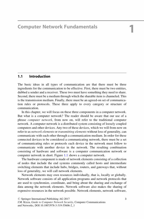
computer network in short. Figure 1.1 shows a computer network.
The hardware component is made of network elements consisting of a collection
of nodes that include the end systems commonly called hosts and intermediate
switching elements that include hubs, bridges, routers, and gateways that, without
loss of generality, we will call network elements.
Network elements may own resources individually, that is, locally or globally.
Network software consists of all application programs and network protocols that
are used to synchronize, coordinate, and bring about the sharing and exchange of
data among the network elements. Network software also makes the sharing of
expensive resources in the network possible. Network elements, network software,
# Springer International Publishing AG 2017
J.M. Kizza, Guide to Computer Network Security, Computer Communications
and Networks, DOI 10.1007/978-3-319-55606-2_1
3
and users all work together so that individual users can exchange messages and
share resources on other systems that are not readily available locally. The network
elements, together with their resources, may be of diverse hardware technologies,
and the software may be as different as possible, but the whole combination must
work together in unison.
Internetworking technology enables multiple, diverse underlying hardware
technologies and different software regimes to interconnect heterogeneous
networks and bring them to communicate smoothly. The smooth working of any
computer communication network is achieved through the low-level mechanisms
provided by the network elements and high-level communication facilities
provided by the software running on the communicating elements. Before we
discuss the working of these networks, let us first look at the different types of
networks.
1.2 Computer Network Models
There are several configuration models that form a computer network. The most
common of these are the centralized and distributed models. In a centralized model,
several computers and devices are interconnected and can talk to each other.
However, there is only one central computer, called the master, through which all
correspondence must take place. Dependent computers, called surrogates, may
have reduced local resources, such as memory, and sharable global resources are
controlled by the master at the center. Unlike the centralized model, however, the
distributed network consists of loosely coupled computers interconnected by a
communication network consisting of connecting elements and communication
channels. The computers themselves may own their resources locally or may
request resources from a remote computer. These computers are known by a string
of names, including host, client, or node. If a host has resources that other hosts
need, then that host is known as a server. Communication and sharing of resources
are not controlled by the central computer but are arranged between any two
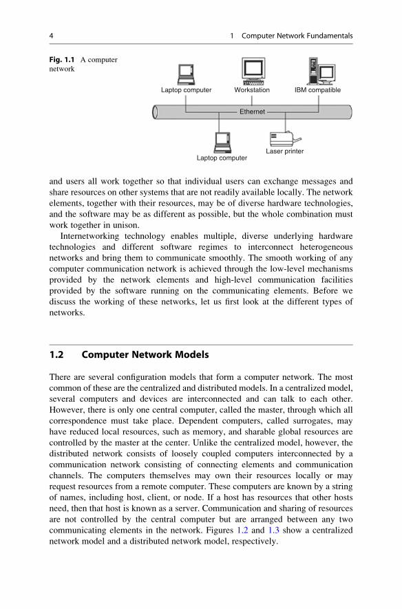
communicating elements in the network. Figures 1.2 and 1.3 show a centralized
network model and a distributed network model, respectively.
Laptop computer
Laptop computerLaser printer
Workstation
Ethernet
IBM compatible
Fig. 1.1 A computer
network
4 1 Computer Network Fundamentals
1.3 Computer Network Types
Computer networks come in different sizes. Each network is a cluster of network
elements and their resources. The size of the cluster determines the network type.
There are, in general, two main network types: the local area network (LAN) and
wide area network (WAN).
1.3.1 Local Area Networks (LANs)
A computer network with two or more computers or clusters of network and their
resources connected by a communication medium sharing communication
protocols and confined in a small geographic area, such as a building floor, a
building, or a few adjacent buildings, is called a local area network (LAN). The
advantage of a LAN is that all network elements are close together so the commu-
nication links maintain a higher speed of data movement. Also, because of the
proximity of the communicating elements, high-cost and high-quality
Surrogate ComputerSurrogate Computer
Surrogate Printer
Surrogate Laptop
Server/MasterFig. 1.2 A centralized
network model
Laptop
Laptop computer
computer
Computer
Workstation
Mac II
Fig. 1.3 A distributed
network model
1.3 Computer Network Types 5
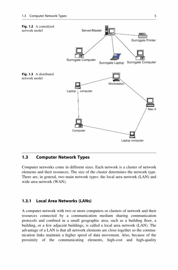
communicating elements can be used to deliver better service and high reliability.
Figure 1.4 shows a LAN.
1.3.2 Wide Area Networks (WANs)
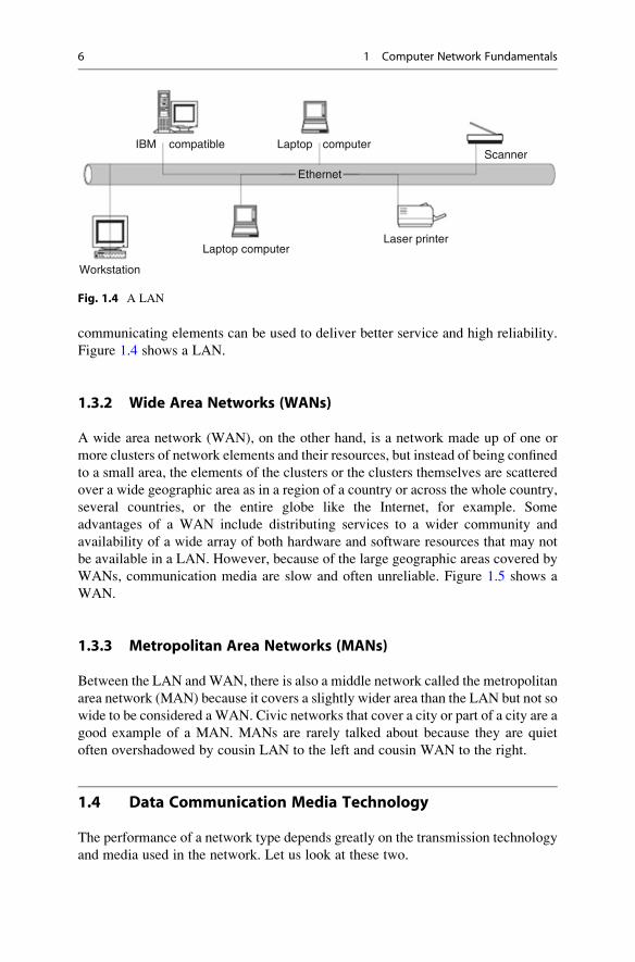
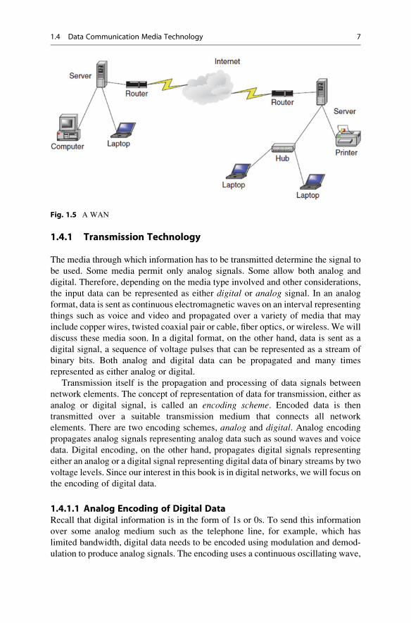
A wide area network (WAN), on the other hand, is a network made up of one or
more clusters of network elements and their resources, but instead of being confined
to a small area, the elements of the clusters or the clusters themselves are scattered
over a wide geographic area as in a region of a country or across the whole country,
several countries, or the entire globe like the Internet, for example. Some
advantages of a WAN include distributing services to a wider community and
availability of a wide array of both hardware and software resources that may not
be available in a LAN. However, because of the large geographic areas covered by
WANs, communication media are slow and often unreliable. Figure 1.5 shows a
WAN.
1.3.3 Metropolitan Area Networks (MANs)
Between the LAN and WAN, there is also a middle network called the metropolitan
area network (MAN) because it covers a slightly wider area than the LAN but not so
wide to be considered aWAN. Civic networks that cover a city or part of a city are a
good example of a MAN. MANs are rarely talked about because they are quiet
often overshadowed by cousin LAN to the left and cousin WAN to the right.
1.4 Data Communication Media Technology
The performance of a network type depends greatly on the transmission technology
and media used in the network. Let us look at these two.
Laptop computer
Laptop
Laser printer
Workstation
IBM compatibleScanner
Ethernet
computer
Fig. 1.4 A LAN
6 1 Computer Network Fundamentals
1.4.1 Transmission Technology
The media through which information has to be transmitted determine the signal to
be used. Some media permit only analog signals. Some allow both analog and
digital. Therefore, depending on the media type involved and other considerations,
the input data can be represented as either digital or analog signal. In an analog
format, data is sent as continuous electromagnetic waves on an interval representing
things such as voice and video and propagated over a variety of media that may
include copper wires, twisted coaxial pair or cable, fiber optics, or wireless. We will
discuss these media soon. In a digital format, on the other hand, data is sent as a
digital signal, a sequence of voltage pulses that can be represented as a stream of
binary bits. Both analog and digital data can be propagated and many times
represented as either analog or digital.
Transmission itself is the propagation and processing of data signals between
network elements. The concept of representation of data for transmission, either as
analog or digital signal, is called an encoding scheme. Encoded data is then
transmitted over a suitable transmission medium that connects all network
elements. There are two encoding schemes, analog and digital. Analog encoding
propagates analog signals representing analog data such as sound waves and voice
data. Digital encoding, on the other hand, propagates digital signals representing
either an analog or a digital signal representing digital data of binary streams by two
voltage levels. Since our interest in this book is in digital networks, we will focus on
the encoding of digital data.
1.4.1.1 Analog Encoding of Digital DataRecall that digital information is in the form of 1s or 0s. To send this information
over some analog medium such as the telephone line, for example, which has
limited bandwidth, digital data needs to be encoded using modulation and demod-
ulation to produce analog signals. The encoding uses a continuous oscillating wave,
Fig. 1.5 A WAN
1.4 Data Communication Media Technology 7
usually a sine wave, with a constant frequency signal called a carrier signal. Thecarrier has three modulation characteristics: amplitude, frequency, and phase shift.The scheme then uses a modem, a modulation-demodulation pair, to modulate and
demodulate the data signal based on any one of the three carrier characteristics or a
combination. The resulting wave is between a range of frequencies on both sides of
the carrier as shown below [1]:
• Amplitude modulation represents each binary value by a different amplitude of
the carrier frequency. The absence of or low carrier frequency may represent a
0 and any other frequency then represents a 1. But this is a rather inefficient
modulation technique and is therefore used only at low frequencies up to
1200 bps in voice grade lines.
• Frequency modulation also represents the two binary values by two different
frequencies close to the frequency of the underlying carrier. Higher frequencies
represent a 1 and low frequencies represent a 0. The scheme is less susceptible to
errors.
• Phase shift modulation changes the timing of the carrier wave, shifting the
carrier phase to encode the data. A 1 is encoded as a change in phase by
180 degrees and a 0 may be encoded as a 0 change in phase of a carrier signal.
This is the most efficient scheme of the three and it can reach a transmission rate
of up to 9600 bps.
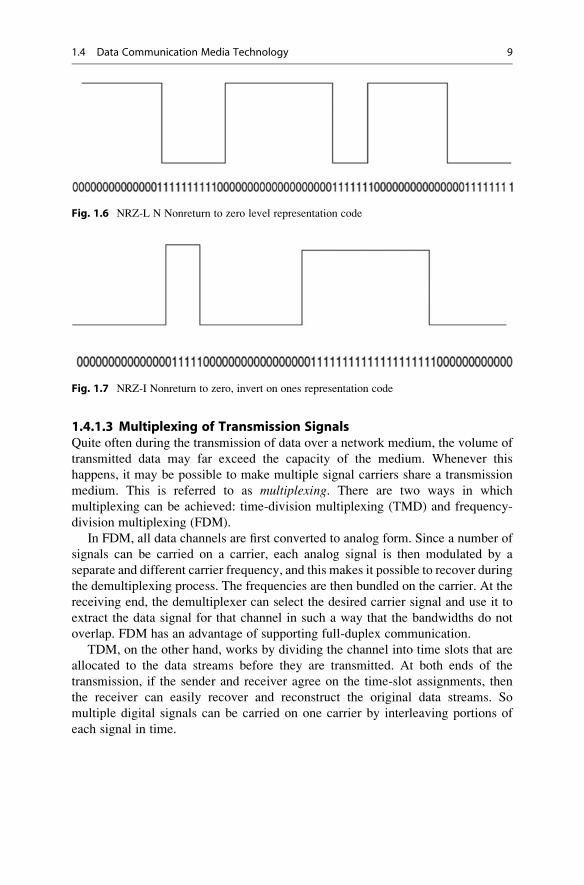
1.4.1.2 Digital Encoding of Digital DataIn this encoding scheme, which offers the most common and easiest way to transmit
digital signals, two binary digits are used to represent two different voltages. Within
a computer, these voltages are commonly 0 and 5 volts. Another procedure uses two
representation codes: nonreturn to zero level (NRZ-L), in which negative voltage
represents binary one and positive voltage represents binary zero, and nonreturn tozero, invert on ones (NRZ-I). See Figs. 1.6 and 1.7 for an example of these two
codes. In NRZ-L, whenever a 1 occurs, a transition from one voltage level to
another is used to signal the information. One problem with NRZ signaling
techniques is the requirement of a perfect synchronization between the receiver
and transmitter clocks. This is, however, reduced by sending a separate clock
signal. There are yet other representations such as the Manchester and differential
Manchester, which encode clock information along with the data.
One may wonder why go through the hassle of digital encoding and transmis-
sion. There are several advantages over its cousin, analog encoding. These include
the following:
• Plummeting costs of digital circuitry
• More efficient integration of voice, video, text, and image
• Reduction of noise and other signal impairment because of the use of repeaters
• Capacity of channels is utilized best with digital techniques
• Better encryption and hence better security than in analog transmission
8 1 Computer Network Fundamentals
1.4.1.3 Multiplexing of Transmission SignalsQuite often during the transmission of data over a network medium, the volume of
transmitted data may far exceed the capacity of the medium. Whenever this
happens, it may be possible to make multiple signal carriers share a transmission
medium. This is referred to as multiplexing. There are two ways in which
multiplexing can be achieved: time-division multiplexing (TMD) and frequency-
division multiplexing (FDM).
In FDM, all data channels are first converted to analog form. Since a number of
signals can be carried on a carrier, each analog signal is then modulated by a
separate and different carrier frequency, and this makes it possible to recover during
the demultiplexing process. The frequencies are then bundled on the carrier. At the
receiving end, the demultiplexer can select the desired carrier signal and use it to
extract the data signal for that channel in such a way that the bandwidths do not
overlap. FDM has an advantage of supporting full-duplex communication.
TDM, on the other hand, works by dividing the channel into time slots that are
allocated to the data streams before they are transmitted. At both ends of the
transmission, if the sender and receiver agree on the time-slot assignments, then
the receiver can easily recover and reconstruct the original data streams. So
multiple digital signals can be carried on one carrier by interleaving portions of
each signal in time.
Fig. 1.6 NRZ-L N Nonreturn to zero level representation code
Fig. 1.7 NRZ-I Nonreturn to zero, invert on ones representation code
1.4 Data Communication Media Technology 9
1.4.2 Transmission Media
As we have observed above, in any form of communication, there must be a
medium through which the communication can take place. So network elements
in a network need a medium in order to communicate. No network can function
without a transmission medium because there would be no connection between the
transmitting elements. The transmission medium plays a vital role in the perfor-
mance of the network. In total, characteristic quality, dependability, and overall
performance of a network depend heavily on its transmission medium. The trans-
mission medium also determines a network’s capacity in realizing the expected
network traffic, reliability for the network’s availability, size of the network in
terms of the distance covered, and the transmission rate. Network transmission
media can be either wired or wireless.
1.4.2.1 Wired Transmission MediaWired transmission media are used in fixed networks physically connecting every
network element. There are different types of physical media, the most common of
which are copper wires, twisted pair, coaxial cables, and optical fibers.
Copper wires have been traditionally used in communication because of their low
resistance to electrical currents that allows signals to travel even further. But copper
wires suffer interference from electromagnetic energy in the environment, and
because of this, they must always be insulated.
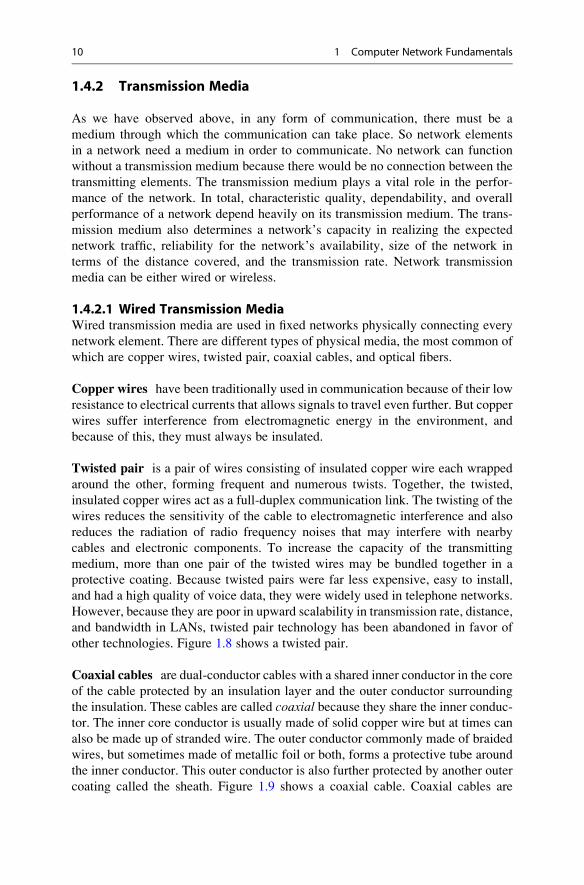
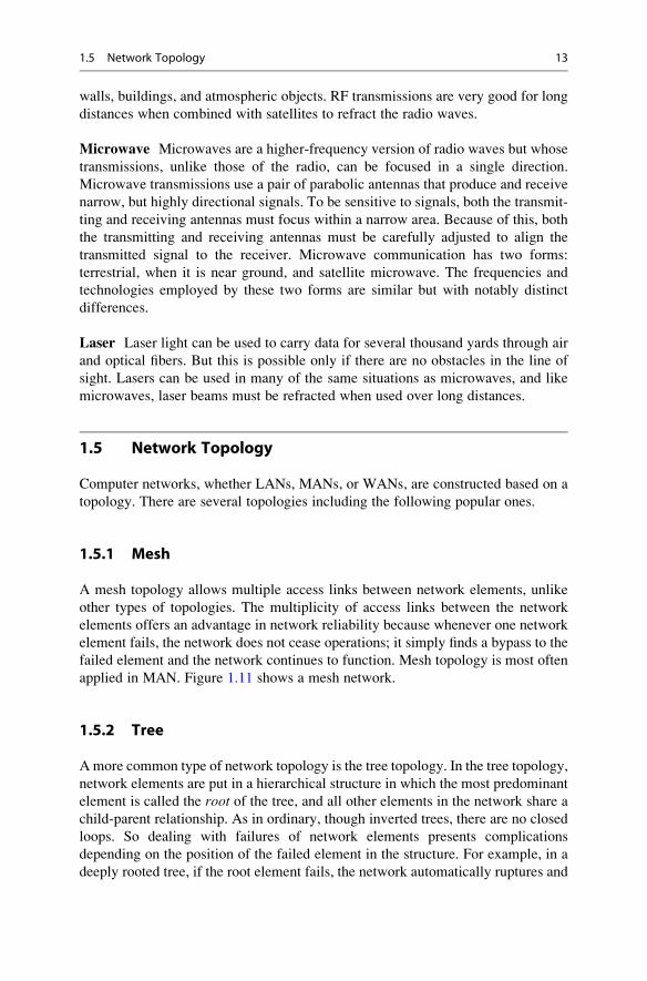
Twisted pair is a pair of wires consisting of insulated copper wire each wrapped
around the other, forming frequent and numerous twists. Together, the twisted,
insulated copper wires act as a full-duplex communication link. The twisting of the
wires reduces the sensitivity of the cable to electromagnetic interference and also
reduces the radiation of radio frequency noises that may interfere with nearby
cables and electronic components. To increase the capacity of the transmitting
medium, more than one pair of the twisted wires may be bundled together in a
protective coating. Because twisted pairs were far less expensive, easy to install,
and had a high quality of voice data, they were widely used in telephone networks.
However, because they are poor in upward scalability in transmission rate, distance,
and bandwidth in LANs, twisted pair technology has been abandoned in favor of
other technologies. Figure 1.8 shows a twisted pair.
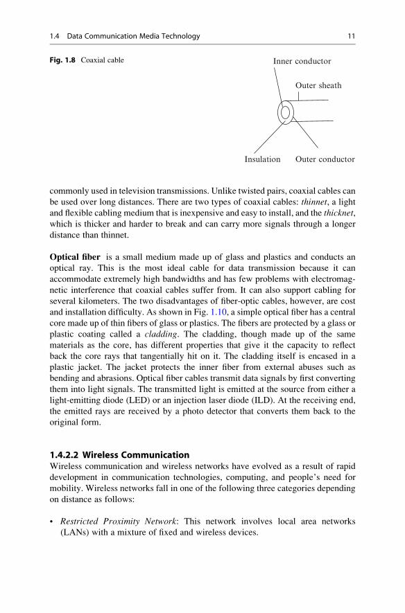
Coaxial cables are dual-conductor cables with a shared inner conductor in the core
of the cable protected by an insulation layer and the outer conductor surrounding
the insulation. These cables are called coaxial because they share the inner conduc-tor. The inner core conductor is usually made of solid copper wire but at times can
also be made up of stranded wire. The outer conductor commonly made of braided
wires, but sometimes made of metallic foil or both, forms a protective tube around
the inner conductor. This outer conductor is also further protected by another outer
coating called the sheath. Figure 1.9 shows a coaxial cable. Coaxial cables are
10 1 Computer Network Fundamentals
commonly used in television transmissions. Unlike twisted pairs, coaxial cables can
be used over long distances. There are two types of coaxial cables: thinnet, a lightand flexible cabling medium that is inexpensive and easy to install, and the thicknet,which is thicker and harder to break and can carry more signals through a longer
distance than thinnet.
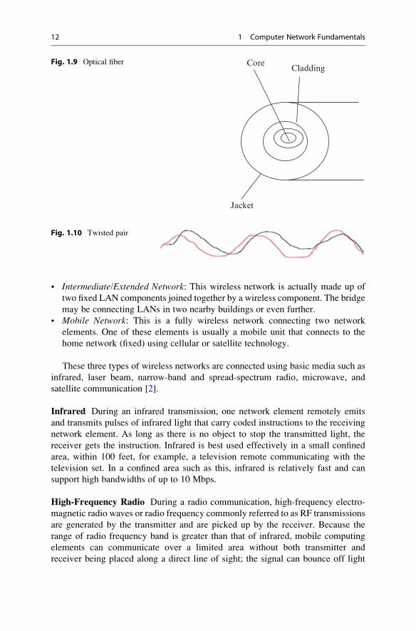
Optical fiber is a small medium made up of glass and plastics and conducts an
optical ray. This is the most ideal cable for data transmission because it can
accommodate extremely high bandwidths and has few problems with electromag-
netic interference that coaxial cables suffer from. It can also support cabling for
several kilometers. The two disadvantages of fiber-optic cables, however, are cost
and installation difficulty. As shown in Fig. 1.10, a simple optical fiber has a central
core made up of thin fibers of glass or plastics. The fibers are protected by a glass or
plastic coating called a cladding. The cladding, though made up of the same
materials as the core, has different properties that give it the capacity to reflect
back the core rays that tangentially hit on it. The cladding itself is encased in a
plastic jacket. The jacket protects the inner fiber from external abuses such as
bending and abrasions. Optical fiber cables transmit data signals by first converting
them into light signals. The transmitted light is emitted at the source from either a
light-emitting diode (LED) or an injection laser diode (ILD). At the receiving end,
the emitted rays are received by a photo detector that converts them back to the
original form.
1.4.2.2 Wireless CommunicationWireless communication and wireless networks have evolved as a result of rapid
development in communication technologies, computing, and people’s need for
mobility. Wireless networks fall in one of the following three categories depending
on distance as follows:
• Restricted Proximity Network: This network involves local area networks
(LANs) with a mixture of fixed and wireless devices.
Inner conductor
Outer conductor
Outer sheath
Insulation
Fig. 1.8 Coaxial cable
1.4 Data Communication Media Technology 11
• Intermediate/Extended Network: This wireless network is actually made up of
two fixed LAN components joined together by a wireless component. The bridge
may be connecting LANs in two nearby buildings or even further.
• Mobile Network: This is a fully wireless network connecting two network
elements. One of these elements is usually a mobile unit that connects to the
home network (fixed) using cellular or satellite technology.
These three types of wireless networks are connected using basic media such as
infrared, laser beam, narrow-band and spread-spectrum radio, microwave, and
satellite communication [2].
Infrared During an infrared transmission, one network element remotely emits
and transmits pulses of infrared light that carry coded instructions to the receiving
network element. As long as there is no object to stop the transmitted light, the
receiver gets the instruction. Infrared is best used effectively in a small confined
area, within 100 feet, for example, a television remote communicating with the
television set. In a confined area such as this, infrared is relatively fast and can
support high bandwidths of up to 10 Mbps.
High-Frequency Radio During a radio communication, high-frequency electro-
magnetic radio waves or radio frequency commonly referred to as RF transmissions
are generated by the transmitter and are picked up by the receiver. Because the
range of radio frequency band is greater than that of infrared, mobile computing
elements can communicate over a limited area without both transmitter and
receiver being placed along a direct line of sight; the signal can bounce off light
CoreCladding
Jacket
Fig. 1.9 Optical fiber
Fig. 1.10 Twisted pair
12 1 Computer Network Fundamentals
walls, buildings, and atmospheric objects. RF transmissions are very good for long
distances when combined with satellites to refract the radio waves.
Microwave Microwaves are a higher-frequency version of radio waves but whose
transmissions, unlike those of the radio, can be focused in a single direction.
Microwave transmissions use a pair of parabolic antennas that produce and receive
narrow, but highly directional signals. To be sensitive to signals, both the transmit-
ting and receiving antennas must focus within a narrow area. Because of this, both
the transmitting and receiving antennas must be carefully adjusted to align the
transmitted signal to the receiver. Microwave communication has two forms:
terrestrial, when it is near ground, and satellite microwave. The frequencies and
technologies employed by these two forms are similar but with notably distinct
differences.
Laser Laser light can be used to carry data for several thousand yards through air
and optical fibers. But this is possible only if there are no obstacles in the line of
sight. Lasers can be used in many of the same situations as microwaves, and like
microwaves, laser beams must be refracted when used over long distances.
1.5 Network Topology
Computer networks, whether LANs, MANs, or WANs, are constructed based on a
topology. There are several topologies including the following popular ones.
1.5.1 Mesh
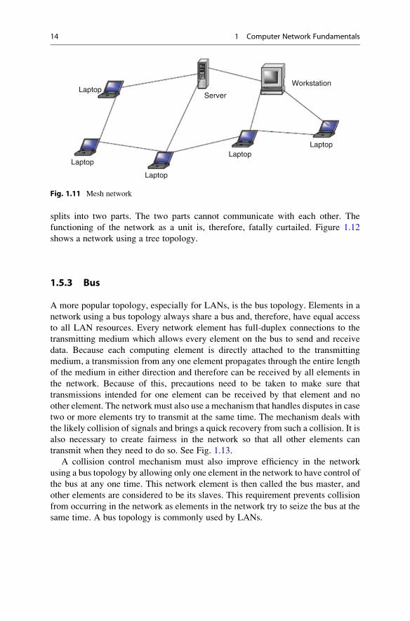
A mesh topology allows multiple access links between network elements, unlike
other types of topologies. The multiplicity of access links between the network
elements offers an advantage in network reliability because whenever one network
element fails, the network does not cease operations; it simply finds a bypass to the
failed element and the network continues to function. Mesh topology is most often
applied in MAN. Figure 1.11 shows a mesh network.
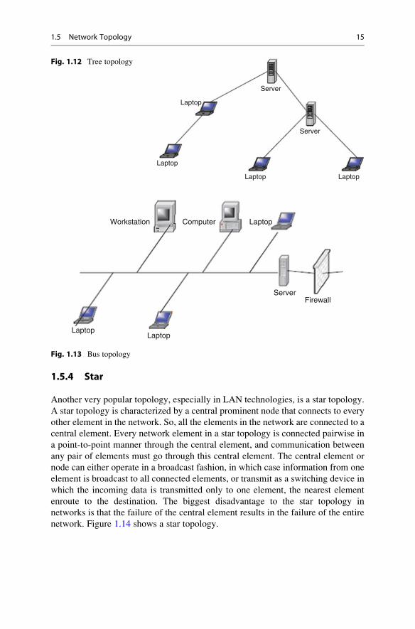
1.5.2 Tree
Amore common type of network topology is the tree topology. In the tree topology,
network elements are put in a hierarchical structure in which the most predominant
element is called the root of the tree, and all other elements in the network share a
child-parent relationship. As in ordinary, though inverted trees, there are no closed
loops. So dealing with failures of network elements presents complications
depending on the position of the failed element in the structure. For example, in a
deeply rooted tree, if the root element fails, the network automatically ruptures and
1.5 Network Topology 13
splits into two parts. The two parts cannot communicate with each other. The
functioning of the network as a unit is, therefore, fatally curtailed. Figure 1.12
shows a network using a tree topology.
1.5.3 Bus
A more popular topology, especially for LANs, is the bus topology. Elements in a
network using a bus topology always share a bus and, therefore, have equal access
to all LAN resources. Every network element has full-duplex connections to the
transmitting medium which allows every element on the bus to send and receive
data. Because each computing element is directly attached to the transmitting
medium, a transmission from any one element propagates through the entire length
of the medium in either direction and therefore can be received by all elements in
the network. Because of this, precautions need to be taken to make sure that
transmissions intended for one element can be received by that element and no
other element. The network must also use a mechanism that handles disputes in case
two or more elements try to transmit at the same time. The mechanism deals with
the likely collision of signals and brings a quick recovery from such a collision. It is
also necessary to create fairness in the network so that all other elements can
transmit when they need to do so. See Fig. 1.13.
A collision control mechanism must also improve efficiency in the network
using a bus topology by allowing only one element in the network to have control of
the bus at any one time. This network element is then called the bus master, and
other elements are considered to be its slaves. This requirement prevents collision
from occurring in the network as elements in the network try to seize the bus at the
same time. A bus topology is commonly used by LANs.
Laptop
Laptop
Laptop
LaptopLaptop
Server
Workstation
Fig. 1.11 Mesh network
14 1 Computer Network Fundamentals
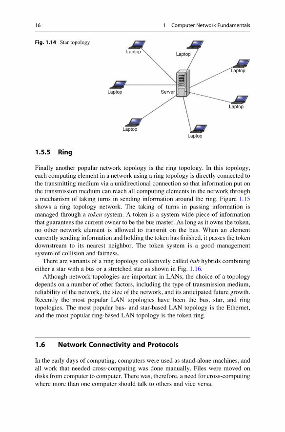
1.5.4 Star
Another very popular topology, especially in LAN technologies, is a star topology.
A star topology is characterized by a central prominent node that connects to every
other element in the network. So, all the elements in the network are connected to a
central element. Every network element in a star topology is connected pairwise in
a point-to-point manner through the central element, and communication between
any pair of elements must go through this central element. The central element or
node can either operate in a broadcast fashion, in which case information from one
element is broadcast to all connected elements, or transmit as a switching device in
which the incoming data is transmitted only to one element, the nearest element
enroute to the destination. The biggest disadvantage to the star topology in
networks is that the failure of the central element results in the failure of the entire
network. Figure 1.14 shows a star topology.
Laptop Laptop
Laptop
Laptop
Server
Server
Fig. 1.12 Tree topology
LaptopLaptop
LaptopWorkstation Computer
ServerFirewall
Fig. 1.13 Bus topology
1.5 Network Topology 15
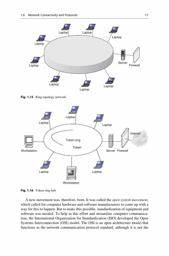
1.5.5 Ring
Finally another popular network topology is the ring topology. In this topology,
each computing element in a network using a ring topology is directly connected to
the transmitting medium via a unidirectional connection so that information put on
the transmission medium can reach all computing elements in the network through
a mechanism of taking turns in sending information around the ring. Figure 1.15
shows a ring topology network. The taking of turns in passing information is
managed through a token system. A token is a system-wide piece of information
that guarantees the current owner to be the bus master. As long as it owns the token,
no other network element is allowed to transmit on the bus. When an element
currently sending information and holding the token has finished, it passes the token
downstream to its nearest neighbor. The token system is a good management
system of collision and fairness.
There are variants of a ring topology collectively called hub hybrids combining
either a star with a bus or a stretched star as shown in Fig. 1.16.
Although network topologies are important in LANs, the choice of a topology
depends on a number of other factors, including the type of transmission medium,
reliability of the network, the size of the network, and its anticipated future growth.
Recently the most popular LAN topologies have been the bus, star, and ring
topologies. The most popular bus- and star-based LAN topology is the Ethernet,
and the most popular ring-based LAN topology is the token ring.
1.6 Network Connectivity and Protocols
In the early days of computing, computers were used as stand-alone machines, and
all work that needed cross-computing was done manually. Files were moved on
disks from computer to computer. There was, therefore, a need for cross-computing
where more than one computer should talk to others and vice versa.
Laptop
Laptop Laptop
LaptopLaptop
Laptop
Laptop
Server
Fig. 1.14 Star topology
16 1 Computer Network Fundamentals
A new movement was, therefore, born. It was called the open system movement,which called for computer hardware and software manufacturers to come up with a
way for this to happen. But to make this possible, standardization of equipment and
software was needed. To help in this effort and streamline computer communica-
tion, the International Organization for Standardization (ISO) developed the Open
Systems Interconnection (OSI) model. The OSI is an open architecture model that
functions as the network communication protocol standard, although it is not the
Laptop
Laptop Laptop
Laptop
Laptop
LaptopLaptop
ServerFirewallLaptop
Fig. 1.15 Ring topology network
Laptop
LaptopLaptop
LaptopLaptop
Workstation
Workstation
Server Firewall
Internet
Token-ring
Token
Fig. 1.16 Token ring hub
1.6 Network Connectivity and Protocols 17
most widely used one. The Transmission Control Protocol/Internet Protocol
(TCP/IP) model, a rival model to OSI, is the most widely used. Both OSI and
TCP/IP models use two protocol stacks, one at the source element and the other at
the destination element.
1.6.1 Open System Interconnection (OSI) Protocol Suite
The development of the OSI model was based on the secure premise that a
communication task over a network can be broken into seven layers, where each
layer represents a different portion of the task. Different layers of the protocol
provide different services and ensure that each layer can communicate only with its
own neighboring layers. That is, the protocols in each layer are based on the
protocols of the previous layers.
Starting from the top of the protocol stack, tasks and information move down
from the top layers until they reach the bottom layer where they are sent out over the
network media from the source system to the destination. At the destination, the
task or information rises back up through the layers until it reaches the top. Each
layer is designed to accept work from the layer above it and to pass work down to
the layer below it, and vice versa. To ease interlayer communication, the interfaces
between the layers are standardized. However, each layer remains independent and
can be designed independently, and each layer’s functionality should not affect the
functionalities of other layers above and below it.
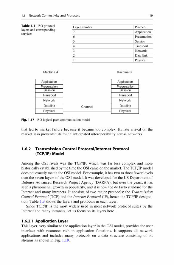
Table 1.1 shows an OSI model consisting of seven layers and the descriptions of
the services provided in each layer.
In peer-to-peer communication, the two communicating computers can initiate
and receive tasks and data. The task and data initiated from each computer start
from the top in the application layer of the protocol stack on each computer. The
tasks and data then move down from the top layers until they reach the bottom
layer, where they are sent out over the network media from the source system to the
destination. At the destination, the task and data rise back up through the layers
until the top. Each layer is designed to accept work from the layer above it and pass
work down to the layer below it. As data passes from layer to layer of the sender
machine, layer headers are appended to the data, causing the datagram to grow
larger. Each layer header contains information for that layer’s peer on the remote
system. That information may indicate how to route the packet through the network
or what should be done to the packet as it is handed back up the layers on the
recipient computer.
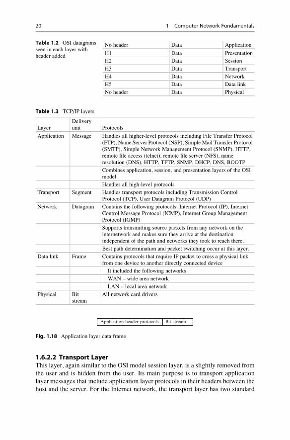
Figure 1.17 shows a logical communication model between two peer computers
using the OSI model. Table 1.2 shows the datagram with added header information
as it moves through the layers. Although the development of the OSI model was
intended to offer a standard for all other proprietary models, and it was as
encompassing of all existing models as possible, it never really replaced many of
those rival models it was intended to replace. In fact it is this “all-in-one” concept
18 1 Computer Network Fundamentals
that led to market failure because it became too complex. Its late arrival on the
market also prevented its much anticipated interoperability across networks.
1.6.2 Transmission Control Protocol/Internet Protocol(TCP/IP) Model
Among the OSI rivals was the TCP/IP, which was far less complex and more
historically established by the time the OSI came on the market. The TCP/IP model
does not exactly match the OSI model. For example, it has two to three fewer levels
than the seven layers of the OSI model. It was developed for the US Department of
Defense Advanced Research Project Agency (DARPA); but over the years, it has
seen a phenomenal growth in popularity, and it is now the de facto standard for the
Internet and many intranets. It consists of two major protocols: the TransmissionControl Protocol (TCP) and the Internet Protocol (IP), hence the TCP/IP designa-
tion. Table 1.3 shows the layers and protocols in each layer.
Since TCP/IP is the most widely used in most network protocol suites by the
Internet and many intranets, let us focus on its layers here.
1.6.2.1 Application LayerThis layer, very similar to the application layer in the OSI model, provides the user
interface with resources rich in application functions. It supports all network
applications and includes many protocols on a data structure consisting of bit
streams as shown in Fig. 1.18.
Table 1.1 ISO protocol
layers and corresponding
services
Layer number Protocol
7 Application
6 Presentation
5 Session
4 Transport
3 Network
2 Data link
1 Physical
Channel
Machine A
Application
PresentaionSession
Transport
Network
Datalink
Physical
Machine B
Application
PresentationSession
Transport
Network
Datalink
Physical
Fig. 1.17 ISO logical peer communication model
1.6 Network Connectivity and Protocols 19
1.6.2.2 Transport LayerThis layer, again similar to the OSI model session layer, is a slightly removed from
the user and is hidden from the user. Its main purpose is to transport application
layer messages that include application layer protocols in their headers between the
host and the server. For the Internet network, the transport layer has two standard
Table 1.2 OSI datagrams
seen in each layer with
header added
No header Data Application
H1 Data Presentation
H2 Data Session
H3 Data Transport
H4 Data Network
H5 Data Data link
No header Data Physical
Table 1.3 TCP/IP layers
Layer
Delivery
unit Protocols
Application Message Handles all higher-level protocols including File Transfer Protocol
(FTP), Name Server Protocol (NSP), Simple Mail Transfer Protocol
(SMTP), Simple Network Management Protocol (SNMP), HTTP,
remote file access (telnet), remote file server (NFS), name
resolution (DNS), HTTP, TFTP, SNMP, DHCP, DNS, BOOTP
Combines application, session, and presentation layers of the OSI
model
Handles all high-level protocols
Transport Segment Handles transport protocols including Transmission Control
Protocol (TCP), User Datagram Protocol (UDP)
Network Datagram Contains the following protocols: Internet Protocol (IP), Internet
Control Message Protocol (ICMP), Internet Group Management
Protocol (IGMP)
Supports transmitting source packets from any network on the
internetwork and makes sure they arrive at the destination
independent of the path and networks they took to reach there.
Best path determination and packet switching occur at this layer.
Data link Frame Contains protocols that require IP packet to cross a physical link
from one device to another directly connected device
It included the following networks
WAN – wide area network
LAN – local area network
Physical Bit
stream
All network card drivers
Application header protocols Bit stream
Fig. 1.18 Application layer data frame
20 1 Computer Network Fundamentals
protocols: Transmission Control Protocol (TCP) and User Datagram Protocol(UDP). TCP provides a connection-oriented service, and it guarantees the delivery
of all application layer packets to their destination. This guarantee is based on two
mechanisms: congestion control that throttles the transmission rate of the source
element when there is traffic congestion in the network and the flow control
mechanism that tries to match sender and receiver speeds to synchronize the flow
rate and reduce the packet drop rate. While TCP offers guarantees of delivery of the
application layer packets, UDP, on the other hand, offers no such guarantees. It
provides a nofrills connectionless service with just delivery and no
acknowledgements. But it is much more efficient and a protocol of choice for
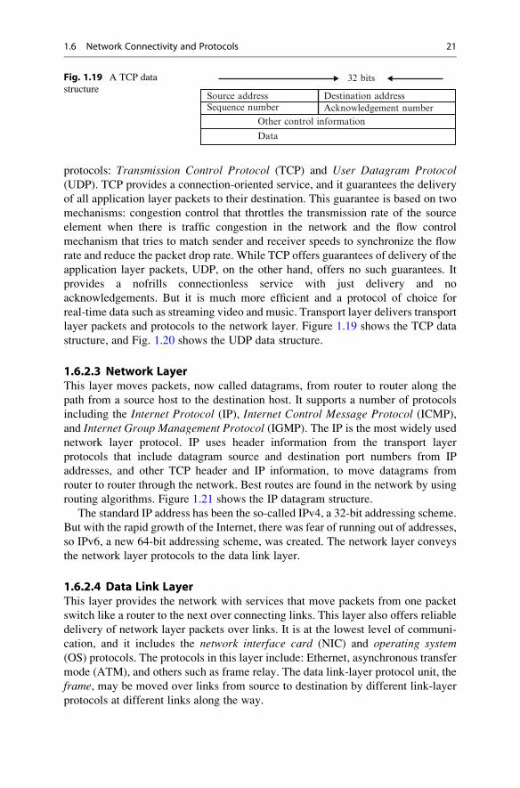
real-time data such as streaming video and music. Transport layer delivers transport
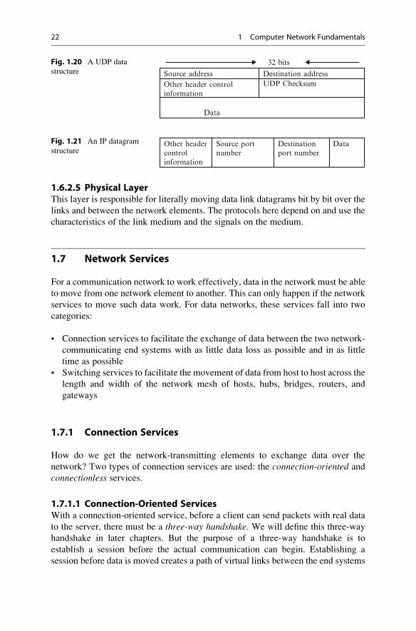
layer packets and protocols to the network layer. Figure 1.19 shows the TCP data
structure, and Fig. 1.20 shows the UDP data structure.
1.6.2.3 Network LayerThis layer moves packets, now called datagrams, from router to router along the
path from a source host to the destination host. It supports a number of protocols
including the Internet Protocol (IP), Internet Control Message Protocol (ICMP),
and Internet Group Management Protocol (IGMP). The IP is the most widely used
network layer protocol. IP uses header information from the transport layer
protocols that include datagram source and destination port numbers from IP
addresses, and other TCP header and IP information, to move datagrams from
router to router through the network. Best routes are found in the network by using
routing algorithms. Figure 1.21 shows the IP datagram structure.
The standard IP address has been the so-called IPv4, a 32-bit addressing scheme.
But with the rapid growth of the Internet, there was fear of running out of addresses,
so IPv6, a new 64-bit addressing scheme, was created. The network layer conveys
the network layer protocols to the data link layer.
1.6.2.4 Data Link LayerThis layer provides the network with services that move packets from one packet
switch like a router to the next over connecting links. This layer also offers reliable
delivery of network layer packets over links. It is at the lowest level of communi-
cation, and it includes the network interface card (NIC) and operating system(OS) protocols. The protocols in this layer include: Ethernet, asynchronous transfer
mode (ATM), and others such as frame relay. The data link-layer protocol unit, the
frame, may be moved over links from source to destination by different link-layer
protocols at different links along the way.
Source addressSequence number
Data
Other control information
Destination addressAcknowledgement number
32 bitsFig. 1.19 A TCP data
structure
1.6 Network Connectivity and Protocols 21
1.6.2.5 Physical LayerThis layer is responsible for literally moving data link datagrams bit by bit over the
links and between the network elements. The protocols here depend on and use the
characteristics of the link medium and the signals on the medium.
1.7 Network Services
For a communication network to work effectively, data in the network must be able
to move from one network element to another. This can only happen if the network
services to move such data work. For data networks, these services fall into two
categories:
• Connection services to facilitate the exchange of data between the two network-
communicating end systems with as little data loss as possible and in as little
time as possible
• Switching services to facilitate the movement of data from host to host across the
length and width of the network mesh of hosts, hubs, bridges, routers, and
gateways
1.7.1 Connection Services
How do we get the network-transmitting elements to exchange data over the
network? Two types of connection services are used: the connection-oriented and
connectionless services.
1.7.1.1 Connection-Oriented ServicesWith a connection-oriented service, before a client can send packets with real data
to the server, there must be a three-way handshake. We will define this three-way
handshake in later chapters. But the purpose of a three-way handshake is to
establish a session before the actual communication can begin. Establishing a
session before data is moved creates a path of virtual links between the end systems
Source address Destination addressUDP ChecksumOther header control
information
Data
32 bitsFig. 1.20 A UDP data
structure
Other headercontrolinformation
Source portnumber
Destinationport number
DataFig. 1.21 An IP datagram
structure
22 1 Computer Network Fundamentals
through a network and, therefore, guarantees the reservation and establishment of
fixed communication channels and other resources needed for the exchange of data
before any data is exchanged and as long as the channels are needed. For example,
this happens whenever we place telephone calls; before we exchange words, the
channels are reserved and established for the duration. Because this technique
guarantees that data will arrive in the same order it was sent in, it is considered to
be reliable. In short the service offers the following:
• Acknowledgments of all data exchanges between the end-systems
• Flow control in the network during the exchange
• Congestion control in the network during the exchange
Depending on the type of physical connections in place and the services required
by the systems that are communicating, connection-oriented methods may be
implemented in the data link layers or in the transport layers of the protocol
stack, although the trend now is to implement it more at the transport layer. For
example, TCP is a connection-oriented transport protocol in the transport layer.
Other network technologies that are connection-oriented include the frame relay
and ATMs.
1.7.1.2 Connectionless ServiceIn a connectionless service, there is no handshaking to establish a session between
the communicating end systems, no flow control, and no congestion control in the
network. This means that a client can start communicating with a server without
warning or inquiry for readiness; it simply sends streams of packets, called
datagrams, from its sending port to the server’s connection port in single point-
to-point transmissions with no relationship established between the packets and
between the end systems. There are advantages and of course disadvantages to this
type of connection service. In brief, the connection is faster because there is no
handshaking which can sometimes be time consuming, and it offers periodic burst
transfers with large quantities of data, and, in addition, it has simple protocol.
However, this service offers minimum services and no safeguards and guarantees to
the sender since there is no prior control information and no acknowledgment. In
addition, the service does not have the reliability of the connection-oriented method
and offers no error handling and no packet ordering; in addition, each packet self-
identifies that leads to long headers, and finally, there is no predefined order in the
arrival of packets.
Like the connection-oriented method, this service can operate both at the data
link and transport layers. For example, UDP, a connectionless service, operates at
the transport layer.
1.7 Network Services 23
1.7.2 Network Switching Services
Before we discuss communication protocols, let us take a detour and briefly discuss
data transfer by a switching element. This is a technique by which data is moved
from host to host across the length and width of the network mesh of hosts, hubs,
bridges, routers, and gateways. This technique is referred to as data switching. Thetype of data switching technique used by a network determines how messages are
transmitted between the two communicating elements and across that network.
There are two types of data switching techniques: circuit switching and packetswitching.
1.7.2.1 Circuit SwitchingIn circuit switching networks, one must reserve all the resources before setting up a
physical communication channel needed for communication. The physical connec-
tion, once established, is then used exclusively by the two end systems, usually
subscribers, for the duration of the communication. The main feature of such a
connection is that it provides a fixed data rate channel, and both subscribers must
operate at this rate. For example, in a telephone communication network, a
connected line is reserved between the two points before the users can start using
the service. One issue of debate on circuit switching is the perceived waste of
resources during the so-called silent periods when the connection is fully in force
but not being used by the parties. This situation occurs when, for example, during a
telephone network session, a telephone receiver is not hung up after use, leaving the
connection still established. During this period, while no one is utilizing the session,
the session line is still open.
1.7.2.2 Packet SwitchingPacket switching networks, on the other hand, do not require any resources to be
reserved before a communication session begins. These networks, however, require
the sending host to assemble all data streams to be transmitted into packets. If a
message is large, it is broken into several packets. Packet headers contain the source
and the destination network addresses of the two communicating end systems.
Then, each of the packets is sent on the communication links and across packet
switches (routers). On receipt of each packet, the router inspects the destination
address contained in the packet. Using its own routing table, each router then
forwards the packet on the appropriate link at the maximum available bit rate. As
each packet is received at each intermediate router, it is forwarded on the appropri-
ate link interspersed with other packets being forwarded on that link. Each router
checks the destination address, if it is the owner of the packet; it then reassembles
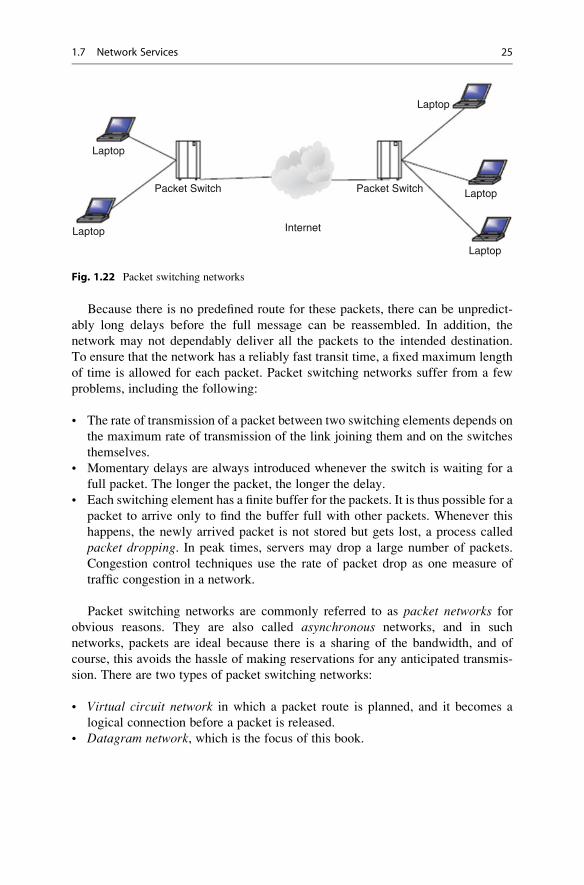
the packets into the final message. Figure 1.22 shows the role of routers in packet
switching networks.
Packet switches are considered to be store-and-forward transmitters, meaning
that they must receive the entire packet before the packet is retransmitted or
switched on to the next switch.
24 1 Computer Network Fundamentals
Because there is no predefined route for these packets, there can be unpredict-
ably long delays before the full message can be reassembled. In addition, the
network may not dependably deliver all the packets to the intended destination.
To ensure that the network has a reliably fast transit time, a fixed maximum length
of time is allowed for each packet. Packet switching networks suffer from a few
problems, including the following:
• The rate of transmission of a packet between two switching elements depends on
the maximum rate of transmission of the link joining them and on the switches
themselves.
• Momentary delays are always introduced whenever the switch is waiting for a
full packet. The longer the packet, the longer the delay.
• Each switching element has a finite buffer for the packets. It is thus possible for a
packet to arrive only to find the buffer full with other packets. Whenever this
happens, the newly arrived packet is not stored but gets lost, a process called
packet dropping. In peak times, servers may drop a large number of packets.
Congestion control techniques use the rate of packet drop as one measure of
traffic congestion in a network.
Packet switching networks are commonly referred to as packet networks for
obvious reasons. They are also called asynchronous networks, and in such
networks, packets are ideal because there is a sharing of the bandwidth, and of
course, this avoids the hassle of making reservations for any anticipated transmis-
sion. There are two types of packet switching networks:
• Virtual circuit network in which a packet route is planned, and it becomes a
logical connection before a packet is released.
• Datagram network, which is the focus of this book.
Laptop
Laptop
Laptop
Laptop
Laptop
Packet Switch Packet Switch
Internet
Fig. 1.22 Packet switching networks
1.7 Network Services 25
1.8 Network Connecting Devices
Before we discuss network connecting devices, let us revisit the network infrastruc-
ture. We have defined a network as a mesh of network elements, commonly referred
to as network nodes, connected together by conducting media. These network nodes
can be either at the ends of the mesh, in which case they are commonly known as
clients or in the middle of the network as transmitting elements. In a small network
such as a LAN, the nodes are connected together via special connecting and
conducting devices that take network traffic from one node and pass it on to the
next node. If the network is big internetwork (large networks of networks like
WANs and LANs), these networks are connected to other special intermediate
networking devices so that the Internet functions as a single large network.
Now let us look at network connecting devices and focus on two types of
devices: those used in networks (small networks such as LANs) and those used in
internetworks.
1.8.1 LAN Connecting Devices
Because LANs are small networks, connecting devices in LANs are less powerful
with limited capabilities. There are hubs, repeaters, bridges, and switches.
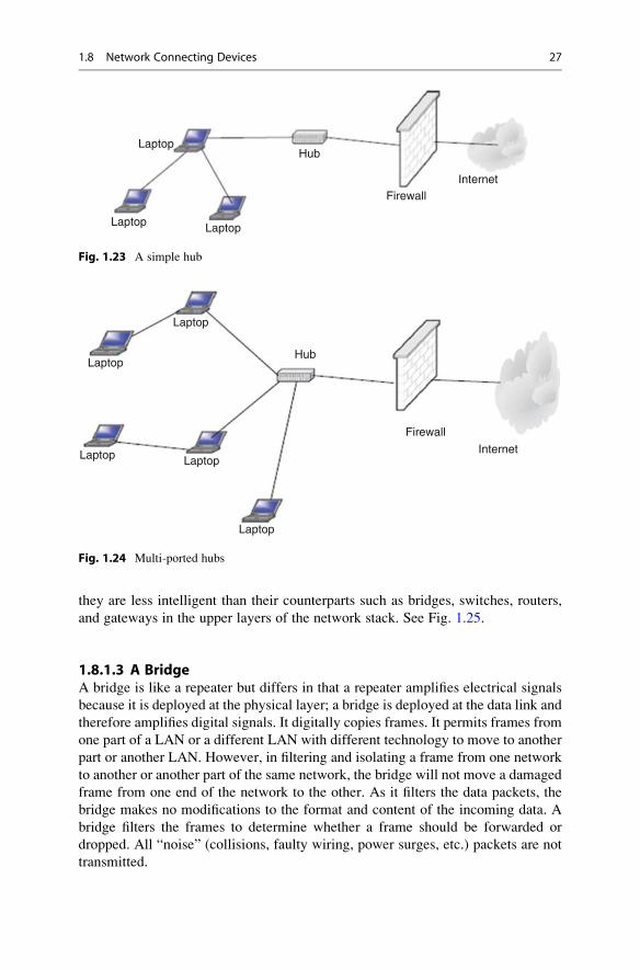
1.8.1.1 A HubThis is the simplest in the family of network connecting devices since it connects
the LAN components with identical protocols. It takes in imports and retransmits
them verbatim. It can be used to switch both digital and analog data. In each node,
presetting must be done to prepare for the formatting of the incoming data. For
example, if the incoming data is in digital format, the hub must pass it on as packets;
however, if the incoming data is analog, then the hub passes as a signal. There are
two types of hubs: simple and multiple port hubs, as shown in Figs. 1.23 and 1.24.
Multiple port hubs may support more than one computer up to its number of ports
and may be used to plan for the network expansion as more computers are added at
a later time.
Network hubs are designed to work with network adapters and cables and can
typically run at either 10 Mbps or 100 Mbps; some hubs can run at both speeds. To
connect computers with differing speeds, it is better to use hubs that run at both
speeds 10/100 Mbps.
1.8.1.2 A RepeaterA network repeater is a low-level local communication device at the physical layer
of the network that receives network signals, amplifies them to restore them to full
strength, and then retransmits them to another node in the network. Repeaters are
used in a network for several purposes including countering the attenuation that
occurs when signals travel long distances and extending the length of the LAN
above the specified maximum. Since they work at the lowest network stack layer,
26 1 Computer Network Fundamentals
they are less intelligent than their counterparts such as bridges, switches, routers,
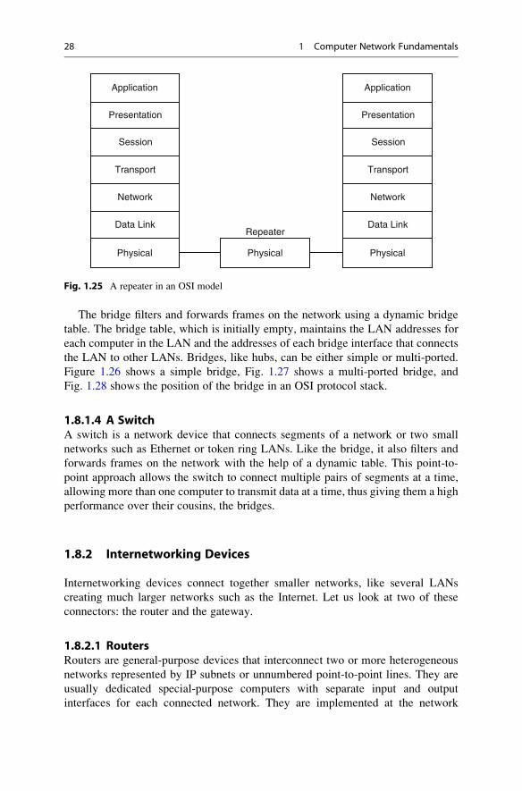
and gateways in the upper layers of the network stack. See Fig. 1.25.
1.8.1.3 A BridgeA bridge is like a repeater but differs in that a repeater amplifies electrical signals
because it is deployed at the physical layer; a bridge is deployed at the data link and
therefore amplifies digital signals. It digitally copies frames. It permits frames from
one part of a LAN or a different LAN with different technology to move to another
part or another LAN. However, in filtering and isolating a frame from one network
to another or another part of the same network, the bridge will not move a damaged
frame from one end of the network to the other. As it filters the data packets, the
bridge makes no modifications to the format and content of the incoming data. A
bridge filters the frames to determine whether a frame should be forwarded or
dropped. All “noise” (collisions, faulty wiring, power surges, etc.) packets are not
transmitted.
Hub
FirewallInternet
Laptop Laptop
Laptop
Fig. 1.23 A simple hub
Laptop
Laptop
Laptop Laptop
Laptop
Hub
Firewall
Internet
Fig. 1.24 Multi-ported hubs
1.8 Network Connecting Devices 27
The bridge filters and forwards frames on the network using a dynamic bridge
table. The bridge table, which is initially empty, maintains the LAN addresses for
each computer in the LAN and the addresses of each bridge interface that connects
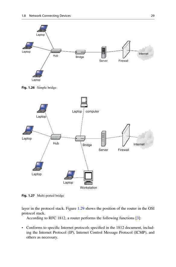
the LAN to other LANs. Bridges, like hubs, can be either simple or multi-ported.
Figure 1.26 shows a simple bridge, Fig. 1.27 shows a multi-ported bridge, and
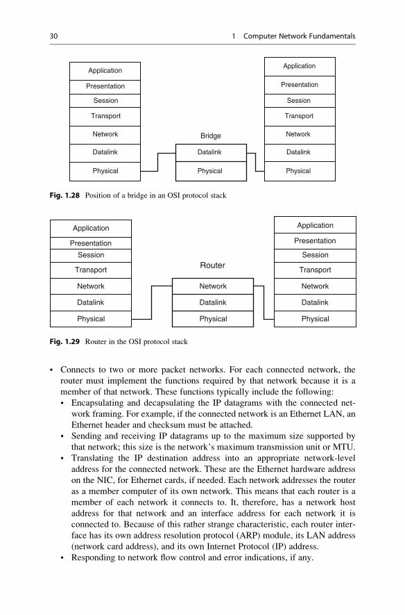
Fig. 1.28 shows the position of the bridge in an OSI protocol stack.
1.8.1.4 A SwitchA switch is a network device that connects segments of a network or two small
networks such as Ethernet or token ring LANs. Like the bridge, it also filters and
forwards frames on the network with the help of a dynamic table. This point-to-
point approach allows the switch to connect multiple pairs of segments at a time,
allowing more than one computer to transmit data at a time, thus giving them a high
performance over their cousins, the bridges.
1.8.2 Internetworking Devices
Internetworking devices connect together smaller networks, like several LANs
creating much larger networks such as the Internet. Let us look at two of these
connectors: the router and the gateway.
1.8.2.1 RoutersRouters are general-purpose devices that interconnect two or more heterogeneous
networks represented by IP subnets or unnumbered point-to-point lines. They are
usually dedicated special-purpose computers with separate input and output
interfaces for each connected network. They are implemented at the network
Physical
Data Link
Network
Transport
Session
Presentation
Application
PhysicalPhysical
RepeaterData Link
Network
Transport
Session
Presentation
Application
Fig. 1.25 A repeater in an OSI model
28 1 Computer Network Fundamentals
layer in the protocol stack. Figure 1.29 shows the position of the router in the OSI
protocol stack.
According to RFC 1812, a router performs the following functions [3]:
• Conforms to specific Internet protocols specified in the 1812 document, includ-
ing the Internet Protocol (IP), Internet Control Message Protocol (ICMP), and
others as necessary.
Laptop
Laptop
Laptop
Hub BridgeServer Firewall
Internet
Fig. 1.26 Simple bridge
Laptop
Laptop
Laptop
Laptop
Laptop
Hub Bridge
Server Firewall
computer
Internet
Workstation
Fig. 1.27 Multi-ported bridge
1.8 Network Connecting Devices 29
• Connects to two or more packet networks. For each connected network, the
router must implement the functions required by that network because it is a
member of that network. These functions typically include the following:
• Encapsulating and decapsulating the IP datagrams with the connected net-
work framing. For example, if the connected network is an Ethernet LAN, an
Ethernet header and checksum must be attached.
• Sending and receiving IP datagrams up to the maximum size supported by
that network; this size is the network’s maximum transmission unit or MTU.
• Translating the IP destination address into an appropriate network-level
address for the connected network. These are the Ethernet hardware address
on the NIC, for Ethernet cards, if needed. Each network addresses the router
as a member computer of its own network. This means that each router is a
member of each network it connects to. It, therefore, has a network host
address for that network and an interface address for each network it is
connected to. Because of this rather strange characteristic, each router inter-
face has its own address resolution protocol (ARP) module, its LAN address
(network card address), and its own Internet Protocol (IP) address.
• Responding to network flow control and error indications, if any.
Application
Presentation
Session
Transport
Network
Datalink
Physical
Application
Presentation
Session
Transport
Network
Datalink
Bridge
Datalink
Physical Physical
Fig. 1.28 Position of a bridge in an OSI protocol stack
Application
Presentation
Session
Transport
Network Network
Router
Datalink
Physical
Datalink
Physical
Application
Presentation
Session
Transport
Network
Datalink
Physical
Fig. 1.29 Router in the OSI protocol stack
30 1 Computer Network Fundamentals
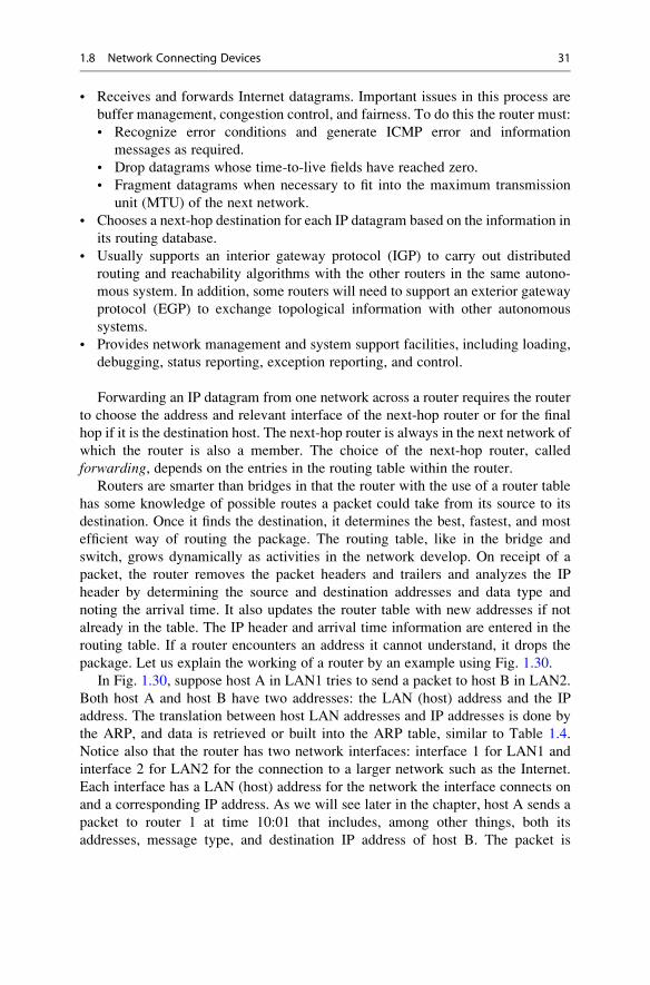
• Receives and forwards Internet datagrams. Important issues in this process are
buffer management, congestion control, and fairness. To do this the router must:
• Recognize error conditions and generate ICMP error and information
messages as required.
• Drop datagrams whose time-to-live fields have reached zero.
• Fragment datagrams when necessary to fit into the maximum transmission
unit (MTU) of the next network.
• Chooses a next-hop destination for each IP datagram based on the information in
its routing database.
• Usually supports an interior gateway protocol (IGP) to carry out distributed
routing and reachability algorithms with the other routers in the same autono-
mous system. In addition, some routers will need to support an exterior gateway
protocol (EGP) to exchange topological information with other autonomous
systems.
• Provides network management and system support facilities, including loading,
debugging, status reporting, exception reporting, and control.
Forwarding an IP datagram from one network across a router requires the router
to choose the address and relevant interface of the next-hop router or for the final
hop if it is the destination host. The next-hop router is always in the next network of
which the router is also a member. The choice of the next-hop router, called
forwarding, depends on the entries in the routing table within the router.
Routers are smarter than bridges in that the router with the use of a router table
has some knowledge of possible routes a packet could take from its source to its
destination. Once it finds the destination, it determines the best, fastest, and most
efficient way of routing the package. The routing table, like in the bridge and
switch, grows dynamically as activities in the network develop. On receipt of a
packet, the router removes the packet headers and trailers and analyzes the IP
header by determining the source and destination addresses and data type and
noting the arrival time. It also updates the router table with new addresses if not
already in the table. The IP header and arrival time information are entered in the
routing table. If a router encounters an address it cannot understand, it drops the
package. Let us explain the working of a router by an example using Fig. 1.30.
In Fig. 1.30, suppose host A in LAN1 tries to send a packet to host B in LAN2.
Both host A and host B have two addresses: the LAN (host) address and the IP
address. The translation between host LAN addresses and IP addresses is done by
the ARP, and data is retrieved or built into the ARP table, similar to Table 1.4.
Notice also that the router has two network interfaces: interface 1 for LAN1 and
interface 2 for LAN2 for the connection to a larger network such as the Internet.
Each interface has a LAN (host) address for the network the interface connects on
and a corresponding IP address. As we will see later in the chapter, host A sends a
packet to router 1 at time 10:01 that includes, among other things, both its
addresses, message type, and destination IP address of host B. The packet is
1.8 Network Connecting Devices 31
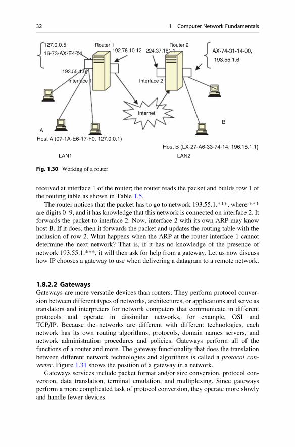
received at interface 1 of the router; the router reads the packet and builds row 1 of
the routing table as shown in Table 1.5.
The router notices that the packet has to go to network 193.55.1.***, where ***
are digits 0–9, and it has knowledge that this network is connected on interface 2. It
forwards the packet to interface 2. Now, interface 2 with its own ARP may know
host B. If it does, then it forwards the packet and updates the routing table with the
inclusion of row 2. What happens when the ARP at the router interface 1 cannot
determine the next network? That is, if it has no knowledge of the presence of
network 193.55.1.***, it will then ask for help from a gateway. Let us now discuss
how IP chooses a gateway to use when delivering a datagram to a remote network.
1.8.2.2 GatewaysGateways are more versatile devices than routers. They perform protocol conver-
sion between different types of networks, architectures, or applications and serve as
translators and interpreters for network computers that communicate in different
protocols and operate in dissimilar networks, for example, OSI and
TCP/IP. Because the networks are different with different technologies, each
network has its own routing algorithms, protocols, domain names servers, and
network administration procedures and policies. Gateways perform all of the
functions of a router and more. The gateway functionality that does the translation
between different network technologies and algorithms is called a protocol con-verter. Figure 1.31 shows the position of a gateway in a network.
Gateways services include packet format and/or size conversion, protocol con-
version, data translation, terminal emulation, and multiplexing. Since gateways
perform a more complicated task of protocol conversion, they operate more slowly
and handle fewer devices.
Internet
Interface 2
192.76.10.12
193.55.1.6)
224.37.181.1
Interface 1
Router 1 Router 2
Host B (LX-27-A6-33-74-14, 196.15.1.1)
Host A (07-1A-E6-17-F0, 127.0.0.1)
LAN1
A
B
AX-74-31-14-00,127.0.0.5
16-73-AX-E4-01
LAN2
193.55.1.6
Fig. 1.30 Working of a router
32 1 Computer Network Fundamentals
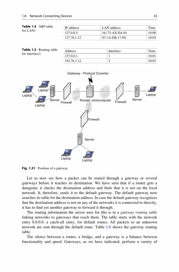
Let us now see how a packet can be routed through a gateway or several
gateways before it reaches its destination. We have seen that if a router gets a
datagram, it checks the destination address and finds that it is not on the local
network. It, therefore, sends it to the default gateway. The default gateway now
searches its table for the destination address. In case the default gateway recognizes
that the destination address is not on any of the networks it is connected to directly,
it has to find yet another gateway to forward it through.
The routing information the server uses for this is in a gateway routing tablelinking networks to gateways that reach them. The table starts with the network
entry 0.0.0.0, a catch-all entry, for default routes. All packets to an unknown
network are sent through the default route. Table 1.6 shows the gateway routing
table.
The choice between a router, a bridge, and a gateway is a balance between
functionality and speed. Gateways, as we have indicated, perform a variety of
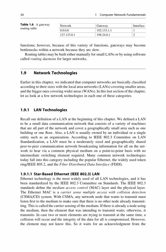
Table 1.4 ARP table
for LAN1IP address LAN address Time
127.0.0.5 16–73-AX-E4–01 10:00
127.76.1.12 07-1A-EB-17-F6 10:03
Table 1.5 Routing table
for interface1Address Interface Time
127.0.0.1 1 10:01
192.76.1.12 2 10:03
Gateway - Protocol Coverter
LaptopLaptopLaptop
Laptop
Laptop Laptop
Server Server
Server
Firewall
Firewall
Router minicomputer Firewall
Fig. 1.31 Position of a gateway
1.8 Network Connecting Devices 33
functions; however, because of this variety of functions, gateways may become
bottlenecks within a network because they are slow.
Routing tables may be built either manually for small LANs or by using software
called routing daemons for larger networks.
1.9 Network Technologies
Earlier in this chapter, we indicated that computer networks are basically classified
according to their sizes with the local area networks (LANs) covering smaller areas,
and the bigger ones covering wider areas (WANs). In this last section of the chapter,
let us look at a few network technologies in each one of these categories.
1.9.1 LAN Technologies
Recall our definition of a LAN at the beginning of this chapter. We defined a LAN
to be a small data communication network that consists of a variety of machines
that are all part of the network and cover a geographically small area such as one
building or one floor. Also, a LAN is usually owned by an individual or a single
entity such as an organization. According to IEEE 802.3 Committee on LAN
Standardization, a LAN must be a moderately sized and geographically shared
peer-to-peer communication network broadcasting information for all on the net-
work to hear via a common physical medium on a point-to-point basis with no
intermediate switching element required. Many common network technologies
today fall into this category including the popular Ethernet, the widely used token
ring/IEEE 805.2, and the Fiber Distributed Data Interface (FDDI).
1.9.1.1 Star-Based Ethernet (IEEE 802.3) LANEthernet technology is the most widely used of all LAN technologies, and it has
been standardized by the IEEE 802.3 Committee on Standards. The IEEE 802.3
standards define the medium access control (MAC) layer and the physical layer.
The Ethernet MAC is a carrier sense multiple access with collision detection(CSMA/CD) system. With CSMA, any network node that wants to transmit must
listen first to the medium to make sure that there is no other node already transmit-
ting. This is called the carrier sensing of the medium. If there is already a node using
the medium, then the element that was intending to transmit waits; otherwise, it
transmits. In case two or more elements are trying to transmit at the same time, a
collision will occur and the integrity of the data for all is compromised. However,
the element may not know this. So it waits for an acknowledgment from the
Table 1.6 A gateway
routing tableNetwork Gateway Interface
0.0.0.0 192.133.1.1 1
127.123.0.1 198.24.0.1 2
34 1 Computer Network Fundamentals
receiving node. The waiting period varies, taking into account maximum round-trip
propagation delay and other unexpected delays. If no acknowledgment is received
during that time, the element then assumes that a collision has occurred, and the
transmission was unsuccessful, and therefore it must retransmit. If more collisions
were to happen, then the element must now double the delay time and so on. After a
collision, when the two elements are in delay period, the medium may be idle and
this may lead to inefficiency. To correct this situation, the elements, instead of just
going into the delay mode, must continue to listen onto the medium as they
transmit. In this case, they will not only be doing carrier sensing but also detecting
a collision that leads to CSMA/CD. According to Stallings, the CSMA/CD scheme
follows the following algorithm [1]:
• If the medium is idle, transmit.
• If the medium is busy, continue to listen until idle, and then transmit
immediately.
• If collision is detected, transmit jamming signal for “collision warning” to all
other network elements.
• After jamming the signal, wait random time units and attempt to transmit.
A number of Ethernet LANs are based on the IEEE 802.3 standards, including
• 10 BASE-X (where X ¼ 2, 5, T and F; T ¼ twisted pair and F ¼ fiber optics)
• 100 BASE-T (where the T options include T4, TX, and FX)
• 1000 BASE-T (where T options include LX, SX, T, and CX)
The basic Ethernet transmission structure is a frame and it is shown in Fig. 1.32.
The source and destination fields contain 6-byte LAN addresses of the form
xx-xx-xx-xx-xx-xx, where x is a hexadecimal integer. The error detection field is
4 bytes of bits used for error detection, usually using the cyclic redundancy check(CRC) algorithm, in which the source and destination elements synchronize the
values of these bits.
1.9.1.2 Token Ring/IEEE 805.2Token ring LANs based on IEEE 805.2 are also used widely in commercial and
small industrial networks, although not as popular as Ethernet. The standard uses a
frame called a token that circulates around the network so that all network nodes
have equal access to it. As we have seen previously, token ring technology employs
a mechanism that involves passing the token around the network so that all network
elements have equal access to it.
Whenever a network element wants to transmit, it waits for the token on the ring
to make its way to the element’s connection point on the ring. When the token
arrives at this point, the element grabs it and changes one bit of the token that
becomes the start bit in the data frame the element will be transmitting. The element
then inserts data, addressing information and other fields, and then releases the
payload onto the ring. It then waits for the token to make a round and come back.
1.9 Network Technologies 35
The receiving host must recognize the destination MAC address within the frame as
its own. Upon receipt, the host identifies the last field indicating the recognition of
the MAC address as its own. The frame contents are then copied by the host, and the
frame is put back in circulation. On reaching the network element that still owns the
token, the element withdraws the token, and a new token is put on the ring for
another network element that may need to transmit.
Because of its round-robin nature, the token ring technique gives each network
element a fair chance of transmitting if it wants to. However, if the token ever gets
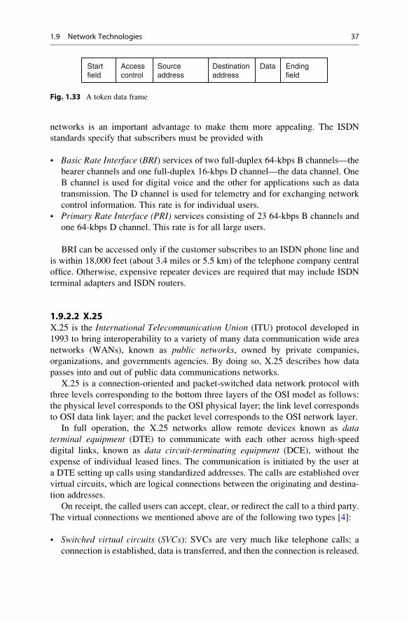
lost, the network business is halted. Figure 1.33 shows the structure of a token data
frame, and Fig. 1.16 shows the token ring structure.
Like Ethernet, the token ring has a variety of technologies based on the trans-
mission rates.
1.9.1.3 Other LAN TechnologiesIn addition to those we have discussed earlier, several other LAN technologies are
in use, including the following:
• Asynchronous transfer mode (ATM) with the goal of transporting real-time
voice, video, text, e-mail, and graphic data. ATM offers a full array of network
services that make it a rival of the Internet network.
• Fiber Distributed Data Interface (FDDI) is a dual-ring network that uses a token
ring scheme with many similarities to the original token ring technology.
• AppleTalk, the popular Mac users’ LAN.
1.9.2 WAN Technologies
As we defined it earlier, WANs are data networks like LANs, but they cover a wider
geographic area. Because of their sizes, WANs traditionally provide fewer services
to customers than LANs. Several networks fall into this category, including the
integrated services digital network (ISDN), X.25, frame relay, and the popular
Internet.
1.9.2.1 Integrated Services Digital Network (ISDN)ISDN is a system of digital phone connections that allows data to be transmitted
simultaneously across the world using end-to-end digital connectivity. It is a
network that supports the transmission of video, voice, and data. Because the
transmission of these varieties of data, including graphics, usually puts widely
differing demands on the communication network, service integration for these
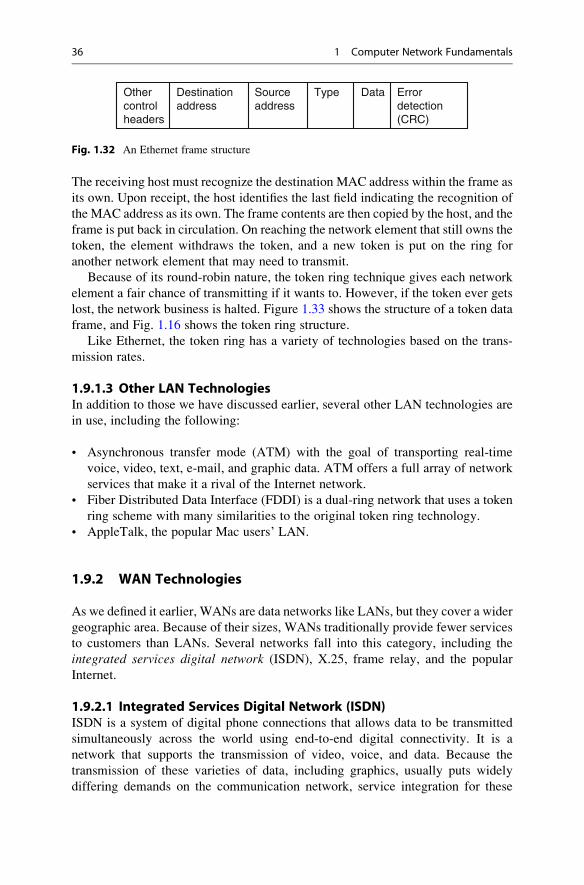
Othercontrolheaders
Destinationaddress
Sourceaddress
Type Data Errordetection(CRC)
Fig. 1.32 An Ethernet frame structure
36 1 Computer Network Fundamentals
networks is an important advantage to make them more appealing. The ISDN
standards specify that subscribers must be provided with
• Basic Rate Interface (BRI) services of two full-duplex 64-kbps B channels—the
bearer channels and one full-duplex 16-kbps D channel—the data channel. One
B channel is used for digital voice and the other for applications such as data
transmission. The D channel is used for telemetry and for exchanging network
control information. This rate is for individual users.
• Primary Rate Interface (PRI) services consisting of 23 64-kbps B channels and
one 64-kbps D channel. This rate is for all large users.
BRI can be accessed only if the customer subscribes to an ISDN phone line and
is within 18,000 feet (about 3.4 miles or 5.5 km) of the telephone company central
office. Otherwise, expensive repeater devices are required that may include ISDN
terminal adapters and ISDN routers.
1.9.2.2 X.25X.25 is the International Telecommunication Union (ITU) protocol developed in
1993 to bring interoperability to a variety of many data communication wide area
networks (WANs), known as public networks, owned by private companies,
organizations, and governments agencies. By doing so, X.25 describes how data
passes into and out of public data communications networks.
X.25 is a connection-oriented and packet-switched data network protocol with
three levels corresponding to the bottom three layers of the OSI model as follows:
the physical level corresponds to the OSI physical layer; the link level corresponds
to OSI data link layer; and the packet level corresponds to the OSI network layer.
In full operation, the X.25 networks allow remote devices known as dataterminal equipment (DTE) to communicate with each other across high-speed
digital links, known as data circuit-terminating equipment (DCE), without theexpense of individual leased lines. The communication is initiated by the user at
a DTE setting up calls using standardized addresses. The calls are established over
virtual circuits, which are logical connections between the originating and destina-
tion addresses.
On receipt, the called users can accept, clear, or redirect the call to a third party.
The virtual connections we mentioned above are of the following two types [4]:
• Switched virtual circuits (SVCs): SVCs are very much like telephone calls; a
connection is established, data is transferred, and then the connection is released.
Startfield
Accesscontrol
Sourceaddress
Destinationaddress
Data Endingfield
Fig. 1.33 A token data frame
1.9 Network Technologies 37
Each DTE on the network is given a unique DTE address that can be used much
like a telephone number.
• Permanent virtual circuits (PVCs): A PVC is similar to a leased line in that the
connection is always present. The logical connection is established permanently
by the packet-switched network administration. Therefore, data may always be
sent without any call setup.
Both of these circuits are used extensively, but since user equipment and
network systems supported both X.25 PVCs and X.25 SVCs, most users prefer
the SVCs since they enable the user devices to set up and tear down connections as
required.
Because X.25 is a reliable data communications with a capability over a wide
range of quality of transmission facilities, it provides advantages over other WAN
technologies, for example,
• Unlike frame relay and ATM technologies that depend on the use of high-quality
digital transmission facilities, X.25 can operate over either analog or digital
facilities.
• In comparison with TCP/IP, one finds that TCP/IP has only end-to-end error
checking and flow control, while X.25 is error checked from network element to
network element.
X.25 networks are in use throughout the world by large organizations with
widely dispersed and communication-intensive operations in sectors such as
finance, insurance, transportation, utilities, and retail.
1.9.2.3 Other WAN TechnologiesThe following are other WAN technologies that we would like to discuss but cannot
include because of space limitations:
• Frame relay is a packet-switched network with the ability to multiplex many
logical data conversions over a single connection. It provides flexible efficient
channel bandwidth using digital and fiber-optic transmission. It has many similar
characteristics to X.25 network except in format and functionality.
• Point-to-Point Protocol (PPP) is the Internet standard for transmission of IP
packets over serial lines. The point-to-point link provides a single,
preestablished communications path from the ending element through a carrier
network, such as a telephone company, to a remote network. These links can
carry datagram or data-stream transmissions.
• xDirect service line (xDSL) is a technology that provides an inexpensive, yet
very fast connection to the Internet.
• Switched multi-megabit data service (SMDS) is a connectionless service
operating in the range of 1.5–100 Mbps; any SMDS station can send a frame
to any other station on the same network.
• Asynchronous transfer mode (ATM) is already discussed as a LAN technology.
38 1 Computer Network Fundamentals
1.9.3 Wireless LANs
The rapid advances, miniaturization, and the popularity of wireless technology have
opened a new component of LAN technology. The mobility and relocation of
workers have forced companies to move into new wireless technologies with
emphasis on wireless networks extending the local LAN into a wireless LAN.
There are basically four types of wireless LANs [1]:
• LAN extension is a quick wireless extension to an existing LAN to accommo-
date new changes in space and mobile units.
• Cross-building interconnection establishes links across buildings between both
wireless and wired LANs.
• Nomadic access establishes a link between a LAN and a mobile wireless
communication device such as a laptop computer.
• Ad hoc networking is a peer-to-peer network temporarily set up to meet some
immediate need. It usually consists of laptops, handheld PCs, and other commu-
nication devices.
• Personal area networks (PANs) that include the popular Bluetooth networks.
There are several wireless IEEE 802.11-based LAN types, including:
• Infrared
• Spread spectrum
• Narrowband microwave
Wireless technology is discussed in further detail in Chapter 17.
1.10 Conclusion
We have developed the theory of computer networks and discussed the topologies,
standards, and technologies of these networks. Because we were limited by space,
we could not discuss a number of interesting and widely used technologies both in
LAN and WAN areas. However, our limited discussion of these technologies
should give the reader an understanding and scope of the changes that are taking
place in network technologies. We hope that the trend will keep the convergence of
the LAN, WAN, and wireless technologies on track so that the alarming number of
different technologies is reduced and basic international standards are established.
Exercises
1. What is a communication protocol?
2. Why do we need communication protocols?
3. List the major protocols discussed in this chapter.
4. In addition to ISO and TCP/IP, what are the other models?
1.10 Conclusion 39
5. Discuss two LAN technologies that are NOT Ethernet or token ring.
6. Why is Ethernet technology more appealing to users than the rest of the LAN
technologies?
7. What do you think are the weak points of TCP/IP?
8. Discuss the pros and cons of four LAN technologies.
9. List four WAN technologies.
10. What technologies are found in MANs? Which of the technologies listed in
8 and 9 can be used in MANs?
Advanced Exercises
1. X.25 and TCP/IP are very similar but there are differences. Discuss these
differences.
2. Discuss the reasons why ISDN failed to catch on as WAN technology.
3. Why is it difficult to establish permanent standards for a technology like WAN
or LAN?
4. Many people see Bluetooth as a personal wireless network (PAN). Why is this
so? What standard does Bluetooth use?
5. Some people think that Bluetooth is a magic technology that is going to change
the world. Read about Bluetooth and discuss this assertion.
6. Discuss the future of wireless LANs.
7. What is a wireless WAN?What kind of technology can be used in it? Is this the
wave of the future?
8. With the future in mind, compare and contrast ATMs and ISDN technologies.
9. Do you foresee a fusion between LAN, MAN, and WAN technologies in the
future? Support your response.
10. Network technology is in transition. Discuss the direction of network
technology.
References
1. Stallings W (2000) Local and metropolitan area network, 6th edn. Prentice Hall, Upper Saddle
River
2. Comar DE (2000) Internetworking with TCP/IP: principles, protocols, and architecture, 4th edn.
Prentice-Hall, Upper Saddle River
3. RFC (1812) Requirements for IP Version 4 Routers. http://www.cis.ohio-state.edu/cgi-bin/rfc/
rfc1812.html#sec-2.2.3
4. Sangoma Technologies http://www.sangoma.com/x25.htm
40 1 Computer Network Fundamentals