Embed Size (px)
Citation preview

Laboratory for Manufacturing Systems and Automation
Associate Professor Dimitris Mourtzis 1/59
Laboratory for Manufacturing Systems and AutomationDepartment of Mechanical Engineering and Aeronautics
University of Patras, Greece
COMPUTER NUMERICAL CONTROL OF MACHINE TOOLS
Dr. Dimitris Mourtzis
Associate professor
Patras, 2017
Laboratory for Manufacturing Systems and Automation
Associate Professor Dimitris Mourtzis 2/59
Chapter 14:
The Numerical Control Lathe

Laboratory for Manufacturing Systems and Automation
Associate Professor Dimitris Mourtzis 3/59
Table of Contents
Chapter 14: The Numerical Control Lathe……………………………………….4
14.1 Conventional & Slant Bed Arrangement.…………….…………………………………………...……….………..8
14.2 Axis Movement on a CNC Lathe…..…………………………………………….…………………………….17
14.3 Tool-holding Methods used on CNC Lathes......………………………………………………….……….21
14.4 Tool Offset Number…………………………..……………………………….……………………….…26
14.5 Other Parts of Modern CNC Lathes………………………………………………………..………37
14.6 How Feedrates are Specified on CNC Lathes…….…………………………………………..42
14.7 Machine Origin and Work Coordinate System……..……………………….……….……..49

Laboratory for Manufacturing Systems and Automation
Associate Professor Dimitris Mourtzis 4/59
Objectives
Describe the difference between a conventional lathe bed arrangement
and a slant bed arrangement, listing the advantages of the slant bed for
NC
Explain axis movement on a CNC lathe
Describe the method of tool-holding used on CNC turning machines
Explain what a tool offset number is
Laboratory for Manufacturing Systems and Automation
Associate Professor Dimitris Mourtzis 5/59
Objectives
Describe two methods of tool selection used on CNC turning machines
Describe how spindle speed is designated on gear head and variable
speed lathes
Explain how feedrates are specified on CNC turning equipment
Define Tool Nose Radius compensation (TNR)

Laboratory for Manufacturing Systems and Automation
Associate Professor Dimitris Mourtzis 6/59
Introduction
Up to this point, the programming features of CNC mills have been dis-
cussed, but numerical control is used for turning equipment as well
For the turning programs discussed in Chapter 14, word address format will
be used
The coding will be a version used with FANUC lathe controllers, designed
to be generic and so to illustrate the basic programming steps involved
A numerical control lab in a school will have equipment that differs in one
way or another from that presented here
Students are advised to familiarize themselves with the codes used for the
machines they will be using
(Seams W., “Computer Numerical Control, Concepts & Programming”)
Laboratory for Manufacturing Systems and Automation
Associate Professor Dimitris Mourtzis 7/59
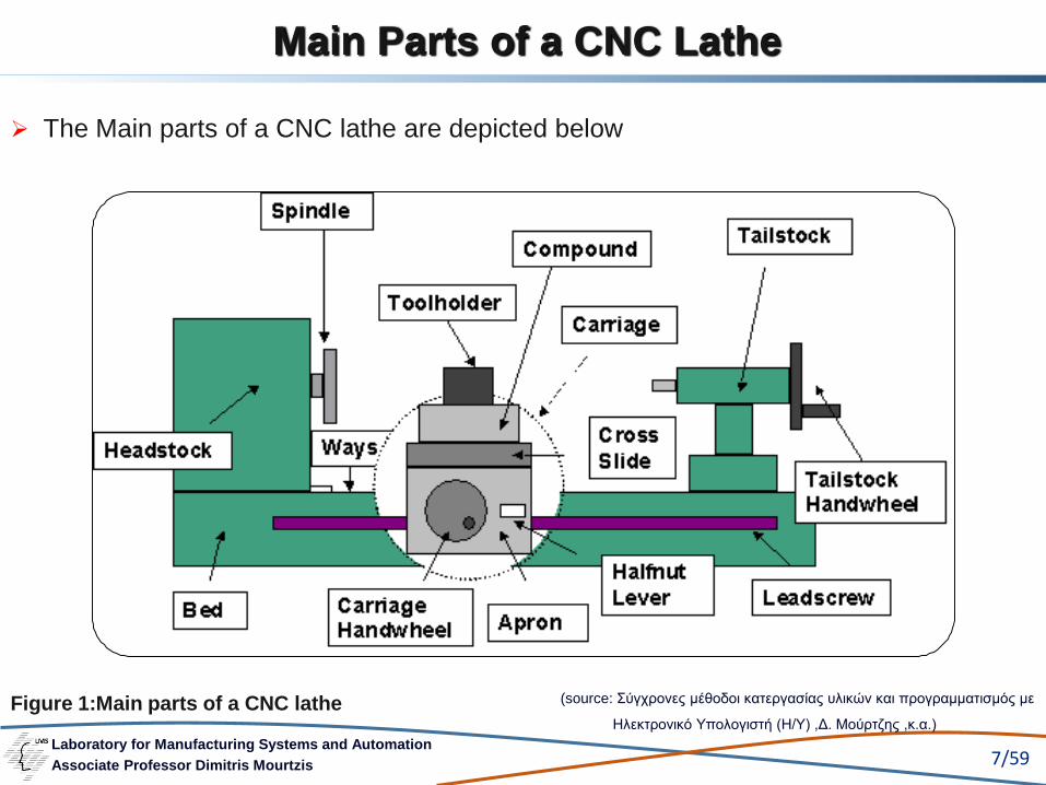
Main Parts of a CNC Lathe
➢ The Main parts of a CNC lathe are depicted below
Figure 1:Main parts of a CNC lathe (source: Σύγχρονες μέθοδοι κατεργασίας υλικών και προγραμματισμός με
Ηλεκτρονικό Υπολογιστή (Η/Υ) ,Δ. Μούρτζης ,κ.α.)

Laboratory for Manufacturing Systems and Automation
Associate Professor Dimitris Mourtzis 8/59
Lathe Bed Design
Older NC lathes, and those that have been converted to numerical control
with retrofit units, look like traditional engine lathes
The lathe carriage rests on the ways
The ways are in the same plane and are parallel to the floor, as illustrated
in Figure 2
This arrangement allows the machinist to reach all the controls readily. Since
the CNC lathe performs its operations automatically, this type of
arrangement is not necessary

Laboratory for Manufacturing Systems and Automation
Associate Professor Dimitris Mourtzis 9/59
In fact, it is quite awkward since the operator will be busy with other
responsibilities while the program is running and will not necessarily be
there to brush the chips off the ways
In a conventional lathe bed arrangement, the chips have nowhere to fall
except on the ways
To overcome this problem, many CNC lathes make use of the slant bed
design illustrated in Figure 3
Lathe Bed Design
Laboratory for Manufacturing Systems and Automation
Associate Professor Dimitris Mourtzis 10/59
Lathe Bed Design
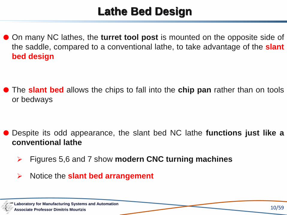
On many NC lathes, the turret tool post is mounted on the opposite side of
the saddle, compared to a conventional lathe, to take advantage of the slant
bed design
The slant bed allows the chips to fall into the chip pan rather than on tools
or bedways
Despite its odd appearance, the slant bed NC lathe functions just like a
conventional lathe
➢ Figures 5,6 and 7 show modern CNC turning machines
➢ Notice the slant bed arrangement

Laboratory for Manufacturing Systems and Automation
Associate Professor Dimitris Mourtzis 11/59
Figure 2: Bed arrangement on a conventional lathe
Lathe carriage rests on the ways
The ways are in the same plane and
parallel to the floor
The ways on a conventional lathe:
Lathe Bed Design
(Adapted from Seams W., “Computer Numerical Control, Concepts &
Programming”)

Laboratory for Manufacturing Systems and Automation
Associate Professor Dimitris Mourtzis 12/59
Lathe Bed Design
Figure 3: Slant bed for NC or CNC lathe
The slant bed arrangement allows the chips to fall into the chip pan rather
than on tools or bedways
(Αdapted from Seams W., “Computer Numerical Control, Concepts & Programming”)
Laboratory for Manufacturing Systems and Automation
Associate Professor Dimitris Mourtzis 13/59
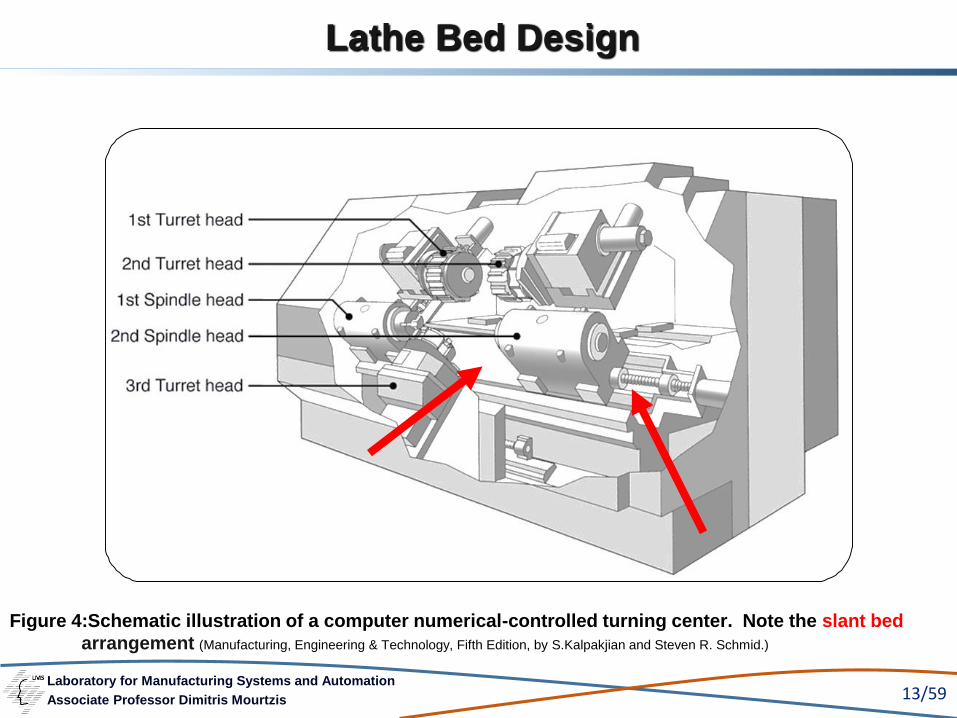
Lathe Bed Design
Figure 4:Schematic illustration of a computer numerical-controlled turning center. Note the slant bed
arrangement (Manufacturing, Engineering & Technology, Fifth Edition, by S.Kalpakjian and Steven R. Schmid.)

Laboratory for Manufacturing Systems and Automation
Associate Professor Dimitris Mourtzis 14/59
Lathe Bed Design
Figure 5:Slant Bed CNC Lathe(Photo courtesy of www.helmancnc.com)

Laboratory for Manufacturing Systems and Automation
Associate Professor Dimitris Mourtzis 15/59
Lathe Bed Design
Figure 6: Modern CNC turning centers(Photo courtesy of HYUNDAI KIA,SKT 460 CNC Turning Centre and MAZAK, Quick Turn Nexus 250MSY)
Chuck Size 381 mm
Bar Capacity 117 mm
Swing Diameter Over Bed 875 mm
Chuck Size 254 mm
Bar Capacity 76 mm
Swing Diameter Over Bed 673 mm

Laboratory for Manufacturing Systems and Automation
Associate Professor Dimitris Mourtzis 16/59
Lathe Bed Design
Figure 7: A five-axis CNC turning center (Photo courtesy of Mazak, Integrex 100-IIIST CNC Turning Center)

Laboratory for Manufacturing Systems and Automation
Associate Professor Dimitris Mourtzis 17/59
Axis Movement
The axis movement of a basic CNC lathe is diagrammed in Figure 8. Some
turning machines, such as that shown in Figure 7, are five-axis machines
In this chapter, only the basic two-axis machine is programmed. The
programming concepts learned on a two-axis machine are the foundation
necessary to program more complex machinery
The basic lathe has only two axes, X and Z
(Seams W., “Computer Numerical Control, Concepts & Programming”)
Laboratory for Manufacturing Systems and Automation
Associate Professor Dimitris Mourtzis 18/59
Axis Movement
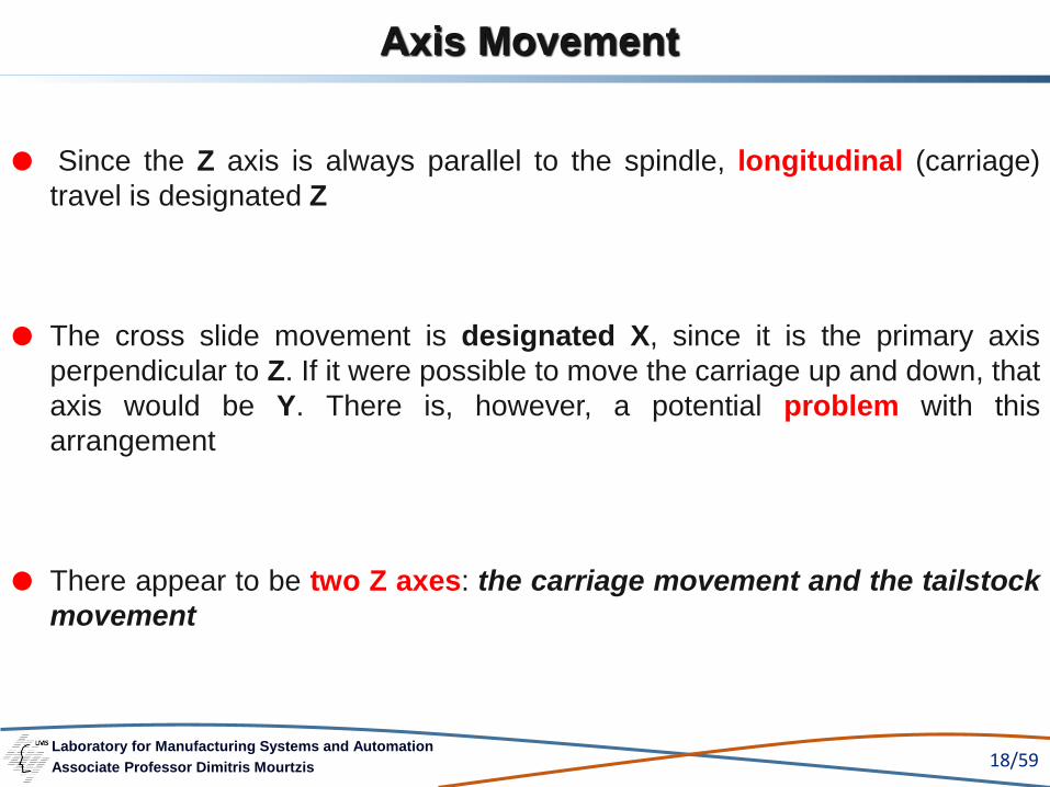
Since the Z axis is always parallel to the spindle, longitudinal (carriage)
travel is designated Z
The cross slide movement is designated X, since it is the primary axis
perpendicular to Z. If it were possible to move the carriage up and down, that
axis would be Y. There is, however, a potential problem with this
arrangement
There appear to be two Z axes: the carriage movement and the tailstock
movement

Laboratory for Manufacturing Systems and Automation
Associate Professor Dimitris Mourtzis 19/59
Axis Movement
Figure 8: Lathe axis movement Z Axis
X A
xis
Basic lathe has only two axes , X and Z
(Adapted from Seams W., “Computer Numerical Control, Concepts &
Programming”)

Laboratory for Manufacturing Systems and Automation
Associate Professor Dimitris Mourtzis 20/59
Axis Movement
To eliminate this problem, the tailstock is usually called the W axis on
lathes with programmable tailstocks
Programmable tailstocks, which are rear turret assemblies on CNC
equipment, are the third and sometimes fourth axes on more complex
equipment
The turning center in Figure 7 has two programmable saddles
In such cases, the axes of the second saddle are usually designated W and
U, with W being saddle travel and U being cross slide travel
There are some imported lathes on which the X-axis direction is reversed.
The programmer must determine if such a situation exists before writing the
lathe program

Laboratory for Manufacturing Systems and Automation
Associate Professor Dimitris Mourtzis 21/59
Toolholders and Tool Changing
Either a rigid toolholder or a tool turret is used to hold the tools on an NC
lathe
Figure 6 shows a CNC chucker employing a rigid toolholder. The turning
center in Figure 7 employs a tool turret in which the various tools needed
for lathe operations are placed in tool-holders
When a tool change is necessary, the appropriate turret is indexed to the
next tool needed
(Seams W., “Computer Numerical Control, Concepts & Programming”)

Laboratory for Manufacturing Systems and Automation
Associate Professor Dimitris Mourtzis 22/59
Simple lathes use six-sided turrets; larger turning machines use eight-, ten-,
and twelve-sided turrets
With the development of robotics, new tool changing and work handling
schemes are appearing. Figure 15 shows a robot arm used for handling
workpieces, and Figure 16 illustrates the robot in operation
To teach the basics of CNC programming, this text will focus on
non-robotic tool change
Toolholders and Tool Changing
Laboratory for Manufacturing Systems and Automation
Associate Professor Dimitris Mourtzis 23/59
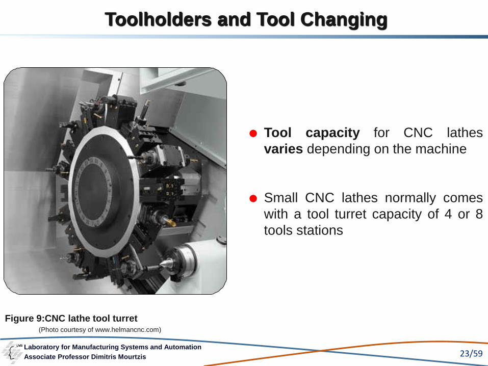
Toolholders and Tool Changing
Tool capacity for CNC lathes
varies depending on the machine
Small CNC lathes normally comes
with a tool turret capacity of 4 or 8
tools stations
Figure 9:CNC lathe tool turret(Photo courtesy of www.helmancnc.com)
Laboratory for Manufacturing Systems and Automation
Associate Professor Dimitris Mourtzis 24/59
Toolholders and Tool Changing
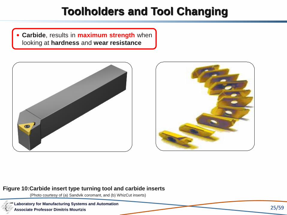
Toolholders used on NC turning machines are of very rigid design
The tools used for turning are of the carbide insert type, made to much
more exacting tolerances than conventional lathe insert tooling
A tool change command in a turning program either changes the turret
position or causes an automatic tool change, depending on the type of
machine used
(Seams W., “Computer Numerical Control, Concepts & Programming”)
Laboratory for Manufacturing Systems and Automation
Associate Professor Dimitris Mourtzis 25/59
Figure 10:Carbide insert type turning tool and carbide inserts(Photo courtesy of (a) Sandvik coromant, and (b) WhizCut inserts)
Carbide, results in maximum strength when
looking at hardness and wear resistance
Toolholders and Tool Changing

Laboratory for Manufacturing Systems and Automation
Associate Professor Dimitris Mourtzis 26/59
Toolholders and Tool Changing
In a CNC turning program for a machine with a rigid toolholder, M06 is used to
initiate an automatic tool change. The T address is used (as it is in milling
programs) to specify the desired tool. The T address also calls up the tool offsets.
The format for automatic tool change is:
➢ Where M06 initiates the tool change,
➢ T is the tool address,
➢ n1 is the tool number, and
➢ n2 is the tool offset number
Turret Position T is used in a similar manner with turret tool selection. The format is:
➢ Where the first number is the turret position and
➢ the second is the tool offset number
M06Tn1 n2
Automatic Tool Change

Laboratory for Manufacturing Systems and Automation
Associate Professor Dimitris Mourtzis 27/59
Toolholders and Tool Changing
Since one tool may be used in several positions, a turret position is used
rather than a tool number. The turret position corresponds to the turret
station number
T01 will index the tool in station one into position
Some NC lathes can utilize more than one tool on a single station. It is
possible, therefore, for T0101 to refer to one tool and T0111 to refer to
another. This is referred to as piggybacking a tool station
Laboratory for Manufacturing Systems and Automation
Associate Professor Dimitris Mourtzis 28/59
One other point should be kept in mind when changing tools: the carriage
(or tailstock) does not necessarily move to a tool change location
It is often necessary, therefore, first to move the carriage or tailstock turret
out of the way before making a tool change
It may also be necessary to program a dwell (G04) to halt the
program, giving the tool time to index to position safely
Toolholders and Tool Changing

Laboratory for Manufacturing Systems and Automation
Associate Professor Dimitris Mourtzis 29/59
Toolholders and Tool Changing
Figure 11:Tool offset diagram

Laboratory for Manufacturing Systems and Automation
Associate Professor Dimitris Mourtzis 30/59
Tool Nose Radius Compensation
The tool nose radius and tool nose vector numbers are optional. They are
entered if using cutter comp
Cutter diameter compensation is called tool nose radius compensation
(TNR comp) on turning machines
The tool radius tells the MCU the amount of compensation that is to be
used. With NC machining centers this value was entered in a comp register
Tool Nose Radius & Standard Tool Nose Vector Numbers
Laboratory for Manufacturing Systems and Automation
Associate Professor Dimitris Mourtzis 31/59
TNR comp is utilized just as cutter comp was in Chapter 10. It can be used
to program the part line or fine tune the tool path to compensate for tool
wear
The major difference is that lathe tools are not completely circular as is a
milling cutter
To aid in proper compensation of the tool path and correctly identify alarm
conditions, a tool nose vector number is entered in the register
Tool Nose Radius Compensation
Laboratory for Manufacturing Systems and Automation
Associate Professor Dimitris Mourtzis 32/59
Tool nose vector numbers tell the MCU the orientation of the tool nose
Figure 12 shows the various directions in which a tool may be oriented
These directions are referred to as vectors
Each vector has a number associated with it that is used to describe the
tool orientation to the MCU
Tool Nose Radius Compensation
(Seams W., “Computer Numerical Control, Concepts & Programming”)

Laboratory for Manufacturing Systems and Automation
Associate Professor Dimitris Mourtzis 33/59
Figure 12: Tool nose vectors
The various directions in which a
tool may be oriented
Tool Nose Radius Compensation
(Adapted from Seams W., “Computer Numerical Control, Concepts & Programming”)

Laboratory for Manufacturing Systems and Automation
Associate Professor Dimitris Mourtzis 34/59
The tool nose may be programmed in one of two ways when TNR comp is
not active:
1. by the tool edge or
2. by the tool nose radius centerline
Tool edge programming is adequate for simple straight line cuts where
the part surfaces intersect each other at right angles
Problems are encountered, when angles and especially arcs are
programmed this way
Figure 17(a) illustrates this point
Tool Edge Programming
Tool Edge versus Centerline Programming
Laboratory for Manufacturing Systems and Automation
Associate Professor Dimitris Mourtzis 35/59
If the tool edge is programmed, the I and K center-points of the illustrated
arc must be shifted. This results in a tool path that does not follow the
desired arc exactly
The amount of error that is induced depends on the size of the cutter and
the radius of the arc
In any case, tool edge programming should not be used when
encountering arcs and angles
Tool Edge Programming
Laboratory for Manufacturing Systems and Automation
Associate Professor Dimitris Mourtzis 36/59
Tool centerline programming is identical to the centerline programming
done when milling
Figure 17(b) demonstrates how the cutter centerlines and part surface
centerlines coincide when the center of the tool nose radius is
programmed
Tool Centerline Programming
Laboratory for Manufacturing Systems and Automation
Associate Professor Dimitris Mourtzis 37/59
Quicksetters
A fairly recent development has been the use of quicksetters—arms with
tool sensors on them
During job setup, the arm is lowered into position, the operator jogs a tool
to the presetting position, and touches it off on the sensor
The quicksetter automatically sets the values of the work coordinate
and the tool offset registers
Other Parts of Modern CNC lathes

Laboratory for Manufacturing Systems and Automation
Associate Professor Dimitris Mourtzis 38/59
Quicksetters can also measure the size of
tools before cutting starts, and
Check for tool damage or breakage during
the machining operation
Figure 13: CNC lathe tool setter (Photo courtesy Renishaw probe systems)
Other Parts of Modern CNC lathes
Laboratory for Manufacturing Systems and Automation
Associate Professor Dimitris Mourtzis 39/59
Other Parts of Modern CNC lathes
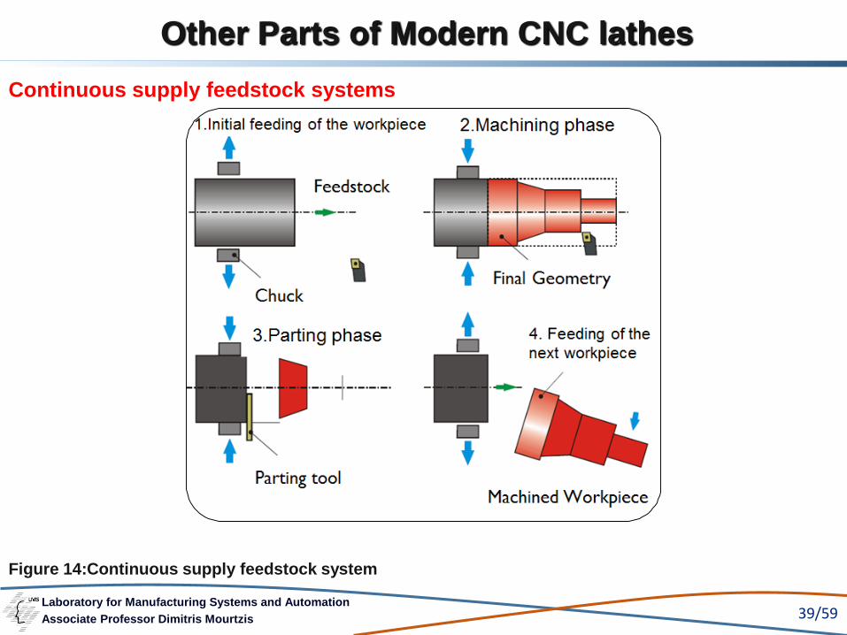
Continuous supply feedstock systems
Figure 14:Continuous supply feedstock system

Laboratory for Manufacturing Systems and Automation
Associate Professor Dimitris Mourtzis 40/59
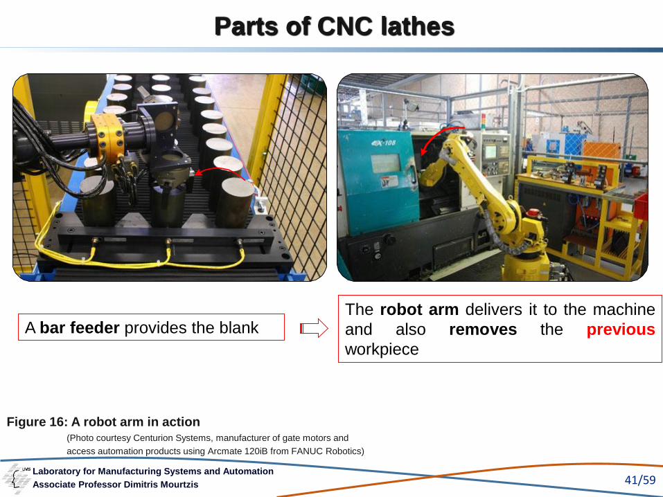
(Photo courtesy of Wanner Engineering, Nakamura-Tome WT-150 lathe, using a Fanuc M16iB robot arm)
Fanuc M16iB robot arm used
for handling workpieces
The second gripper head
allows the exchange of the
previous workpiece
Figure 15: A robot arm used for part load and unload
Other Parts of Modern CNC lathes
Robot arms used for handling workpieces
Laboratory for Manufacturing Systems and Automation
Associate Professor Dimitris Mourtzis 41/59
(Photo courtesy Centurion Systems, manufacturer of gate motors and
access automation products using Arcmate 120iB from FANUC Robotics)
Figure 16: A robot arm in action
A bar feeder provides the blankThe robot arm delivers it to the machine
and also removes the previous
workpiece
Parts of CNC lathes
Laboratory for Manufacturing Systems and Automation
Associate Professor Dimitris Mourtzis 42/59
Spindle Speeds
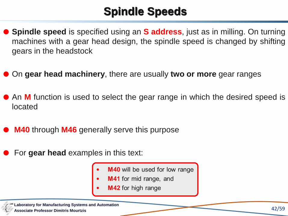
Spindle speed is specified using an S address, just as in milling. On turning
machines with a gear head design, the spindle speed is changed by shifting
gears in the headstock
On gear head machinery, there are usually two or more gear ranges
An M function is used to select the gear range in which the desired speed is
located
M40 through M46 generally serve this purpose
For gear head examples in this text:
Laboratory for Manufacturing Systems and Automation
Associate Professor Dimitris Mourtzis 43/59
Spindle Speeds
The following chart shows a sample of speed ranges for gear head
machines. This chart is not for a particular machine but is representative of
the type of spindle speed spread found on a machine
Some CNC turning machines use a variable speed drive with which an
infinite number of speeds are available between the highest and lowest
speeds
In these cases, the speed is selected using the S address as it is in milling

Laboratory for Manufacturing Systems and Automation
Associate Professor Dimitris Mourtzis 44/59
HIGH RANGE
285 335 380 450
530 660 900 1200
1800 2100 2500 3000
MEDIUM RANGE
55 70 95 120
140 155 175 200
235 260 290 300
LOW RANGE
10 15 20 25
30 40 50 65
75 90 110 125
Chart 1: A sample of speed ranges for gear head machines
Spindle Speeds

Laboratory for Manufacturing Systems and Automation
Associate Professor Dimitris Mourtzis 45/59
Spindle Speeds
Figure 17(a): Error induced by programming tool edge
(Adapted from Seams W., “Computer Numerical Control, Concepts & Programming”)

Laboratory for Manufacturing Systems and Automation
Associate Professor Dimitris Mourtzis 46/59
Spindle Speeds
Figure 17(b):Tool nose centreline programming
(Adapted from Seams W., “Computer Numerical Control, Concepts &
Programming”)

Laboratory for Manufacturing Systems and Automation
Associate Professor Dimitris Mourtzis 47/59
Feed-rates
With a CNC lathe, assigning feedrates is quite simple
A G98 or G94 code (depending on the controller) tells the MCU that the
following feedrate is in inches per minute
➢ For example, G98 F7 specifies a feedrate of 7 inches per minute.
A G99 or G95 in a turning program specifies a feedrate in inches per
revolution
➢ For example, G99 F.015 specifies a feedrate of .015 inch per
revolution
(Seams W., “Computer Numerical Control, Concepts & Programming”)
Laboratory for Manufacturing Systems and Automation
Associate Professor Dimitris Mourtzis 48/59
Machine Origin and Work Coordinate Systems
An NC lathe generally has a fixed zero position assumed by the executive
program upon power-up. This position is known as the home zero or
machine origin
The physical location of this position varies from controller to controller and
machine model to machine model
It is usually one of two locations: X0 = centerline of the spindle, Z0 = the
chuck mounting surface of the spindle, or X0 = extreme X + location, Z0
= extreme Z + location
It is usually necessary to establish a zero point on the part different from
the machine origin location. This position is called the work coordinate
system or part zero

Laboratory for Manufacturing Systems and Automation
Associate Professor Dimitris Mourtzis 49/59
Machine Origin and Work Coordinate Systems
Where:
G50 = the axis preset command
xx.xxxx = the X-axis distance to the part zero
zz.zzzz = the Z-axis distance to the part zero
There are two methods used to accomplish this:
The first method involves the use of an axis preset command—G50. The
G50 transfers the zero point from the home zero to the coordinates
specified with the command
The format for a G50 command is:
G50 Xxx.xxxx Zzz.zzzz
(Seams W., “Computer Numerical Control, Concepts & Programming”)

Laboratory for Manufacturing Systems and Automation
Associate Professor Dimitris Mourtzis 50/59
Machine Origin and Work Coordinate Systems
A G50 command is issued at the start of each tool. Since the programmer
will not know the axis preset distances in advance, zeros should be used or
some other prearranged value in the G50 line
The actual values will be determined by the setup person and
edited in the control when the job is set up
The second method uses registers called work coordinates. These are
registers in the MCU that tell the MCU the distance from home zero to the
part zero

Laboratory for Manufacturing Systems and Automation
Associate Professor Dimitris Mourtzis 51/59
If a machine has more than one available work coordinate, multiple
zero points may be used for complex programming
Another advantage to multiple work coordinates is the ability to have
more than one program loaded in the MCU, each with its own work
coordinate
This is a decided advantage when running several repeating jobs
through a turning center
Machine Origin and Work Coordinate Systems
(Seams W., “Computer Numerical Control, Concepts & Programming”)
Laboratory for Manufacturing Systems and Automation
Associate Professor Dimitris Mourtzis 52/59
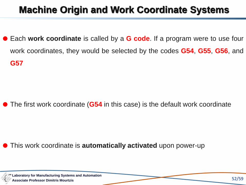
Machine Origin and Work Coordinate Systems
Each work coordinate is called by a G code. If a program were to use four
work coordinates, they would be selected by the codes G54, G55, G56, and
G57
The first work coordinate (G54 in this case) is the default work coordinate
This work coordinate is automatically activated upon power-up

Laboratory for Manufacturing Systems and Automation
Associate Professor Dimitris Mourtzis 53/59
If using only the default work coordinate, the G code may be omitted
The work coordinate values are entered by the setup person when the job
is prepared
The programmer must instruct the setup personnel the position on
the part of the part zero location
Machine Origin and Work Coordinate Systems
(Seams W., “Computer Numerical Control, Concepts & Programming”)
Laboratory for Manufacturing Systems and Automation
Associate Professor Dimitris Mourtzis 54/59
Summary 1/3
CNC turning machines often use a slant bed arrangement to protect the
machine ways from chips. Although different in appearance, the functioning
of a slant bed and conventional bed machine is identical
There are two basic axes, X and Z, on a CNC lathe. If the lathe has
additional axes, they are generally designated U and W
TNR stands for tool nose radius compensation. TNR is the equivalent in
CNC turning to cutter diameter compensation in milling
A tool turret or a rigid toolholder is used to hold the tools on an NC lathe

Laboratory for Manufacturing Systems and Automation
Associate Professor Dimitris Mourtzis 55/59
Tool offset are entered into the MCU prior to running the program to
compensate for minor setup adjustments
A standard tool nose vector number is used to identify the orientation of
a particular tool when using TNR
A tool change command in turning programs will either change the turret
position or cause an automatic tool change, depending on the type of
machine used
The tool change format for turret changing is: T n1 n2
Where T is the tool change command, n1 is the turret position and n2 is the
tool offset
Summary 2/3
Laboratory for Manufacturing Systems and Automation
Associate Professor Dimitris Mourtzis 56/59
Summary
The format for automatic tool change is : M06 T n1 n2
Where M06 initiates the tool change, T is the tool address, n1 is the tool
number, and n2 is the tool offset number
Spindle speeds are specified directly using the S address. On gear head
machines, it is necessary to specify the gear range when selecting a
range outside the active one.
Feedrates on CNC lathes can be specified either in inches per minute
(using G94 or G98), or in inches per revolution (using G95 or G99).
To set a part at X0/Z0 point, it is necessary to transfer the machine origin
to the workpiece using a G code
Laboratory for Manufacturing Systems and Automation
Associate Professor Dimitris Mourtzis 57/59
Vocabulary Introduced in this chapter
Centerline programming
Lathe bed
Quicksetter
Slant bed
Tool edge programming
Tool nose radius
Tool nose vector number
Tool offset numbers
Tool turret
Turret position

Laboratory for Manufacturing Systems and Automation
Associate Professor Dimitris Mourtzis 58/59
1. Chryssolouris G., «Manufacturing Systems: Theory and Practice», 2nd Edition, 2006, Springer-Verlag
2. http://www.centsys.co.za/
3. http://www.dptechnology.com/
4. http://www.sandvik.coromant.com/
5. http://www.hyundai-wiamachine.com/
6. http://www.renishaw.com/
7. Kalpakjian S., «Manufacturing Engineering and Technology», 2nd Edition, 1992, Addison-Wesley Publishing
company
8. Kalpakjian,Schmid,<<Manufacturing Processes for Engineering Materials>>, 5th ed. 2008
9. Mattson M., “CNC Programming, Principles and Applications”, Delmar, 2002
10. Moriwaki T., “Multi-Functional Machine Tool”, CIRP Annals Manufacturing Technology, Vol. 57/2, 2008, pp.
736-749
References

Laboratory for Manufacturing Systems and Automation
Associate Professor Dimitris Mourtzis 59/59
References
11. Seams W., “Computer Numerical Control, Concepts & Programming”, 4th Edition, Delmar, 2002
12. www.mazak.com
13. www.whizcut.com/carbide.html
14. Γ. Χρυσολούρης, «Συστήματα Παραγωγής Θεωρία και Πράξη» Μέρος Ι και ΙΙ, Εκπαιδευτικές Σημειώσεις,
Πανεπιστήμιο Πατρών, 2001,
15. Γ. Χρυσολούρης, Δ. Μούρτζης, Κ. Τσίρμπας, Σ. Καραγιάννης, “Ορθογωνική Κοπή”, Εκπαιδευτικές
Σημειώσεις, Πανεπιστήμιο Πατρών, 2000
16. Γ. Χρυσολούρης, Δ. Μούρτζης, και άλλοι, “Εργαστήρια Μηχανουργικής Τεχνολογίας Ι και ΙI”»,
Εκπαιδευτικές Σημειώσεις για το εργαστήριο του αντιστοίχου μαθήματος, Πανεπιστήμιο Πατρών, 2008
(4η Έκδοση)
17. Δ. Μούρτζης, “Αριθμητικός Έλεγχος Εργαλειομηχανών” Εκπαιδευτικές Σημειώσεις, Πανεπιστήμιο
Πατρών, 2011 (3η Έκδοση)
18. Πετρόπουλου Π.Γ., «Μηχανουργική Τεχνολογία – ΙΙ. Τεχνολογία κατεργασιών κοπής των μετάλλων»,
1998, Εκδόσεις Ζήτη
19. Σύγχρονες μέθοδοι κατεργασίας υλικών και προγραμματισμός με Ηλεκτρονικό Υπολογιστή (Η/Υ) ,Δ.
Μούρτζης ,Κ. Σαλωνίτης