Embed Size (px)
Citation preview

Computer Setup (F10) Utility GuideHP Compaq 6000 Pro Business PCs

© Copyright 2009 Hewlett-PackardDevelopment Company, L.P. Theinformation contained herein is subject tochange without notice.
Microsoft, Windows, and Windows Vista areeither trademarks or registered trademarksof Microsoft Corporation in the United Statesand/or other countries.
The only warranties for HP products andservices are set forth in the express warrantystatements accompanying such productsand services. Nothing herein should beconstrued as constituting an additionalwarranty. HP shall not be liable for technicalor editorial errors or omissions containedherein.
This document contains proprietaryinformation that is protected by copyright. Nopart of this document may be photocopied,reproduced, or translated to anotherlanguage without the prior written consent ofHewlett-Packard Company.
Computer Setup (F10) Utility Guide
HP Compaq 6000 Pro Business PCs
First Edition (September 2009)
Document Part Number: 576437-001

About This BookThis guide provides instructions on how to use Computer Setup. This tool is used to reconfigure andmodify computer default settings when new hardware is installed and for maintenance purposes.
WARNING! Text set off in this manner indicates that failure to follow directions could result in bodilyharm or loss of life.
CAUTION: Text set off in this manner indicates that failure to follow directions could result in damageto equipment or loss of information.
NOTE: Text set off in this manner provides important supplemental information.
ENWW iii

iv About This Book ENWW
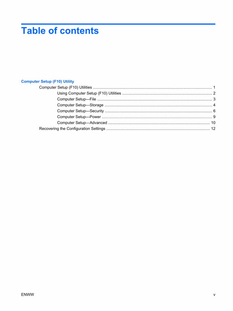
Table of contents
Computer Setup (F10) UtilityComputer Setup (F10) Utilities ............................................................................................................. 1
Using Computer Setup (F10) Utilities .................................................................................. 2Computer Setup—File ......................................................................................................... 3Computer Setup—Storage .................................................................................................. 4Computer Setup—Security .................................................................................................. 6Computer Setup—Power ..................................................................................................... 9Computer Setup—Advanced ............................................................................................. 10
Recovering the Configuration Settings ............................................................................................... 12
ENWW v

vi ENWW

Computer Setup (F10) Utility
Computer Setup (F10) UtilitiesUse Computer Setup (F10) Utility to do the following:
● Change factory default settings.
● Set the system date and time.
● Set, view, change, or verify the system configuration, including settings for processor, graphics,memory, audio, storage, communications, and input devices.
● Modify the boot order of bootable devices such as hard drives, optical drives, or USB flash mediadevices.
● Enable Quick Boot, which is faster than Full Boot but does not run all of the diagnostic tests runduring a Full Boot. You can set the system to:
❑ always Quick Boot (default);
❑ periodically Full Boot (from every 1 to 30 days); or
❑ always Full Boot.
● Select Post Messages Enabled or Disabled to change the display status of Power-On Self-Test(POST) messages. Post Messages Disabled suppresses most POST messages, such as memorycount, product name, and other non-error text messages. If a POST error occurs, the error isdisplayed regardless of the mode selected. To manually switch to Post Messages Enabled duringPOST, press any key (except F1 through F12).
● Establish an Ownership Tag, the text of which is displayed each time the system is turned on orrestarted.
● Enter the Asset Tag or property identification number assigned by the company to this computer.
● Enable the power-on password prompt during system restarts (warm boots) as well as duringpower-on.
● Establish a setup password that controls access to the Computer Setup (F10) Utility and thesettings described in this section.
● Secure integrated I/O functionality, including the serial, USB, or parallel ports, audio, or embeddedNIC, so that they cannot be used until they are unsecured.
● Enable or disable removable media boot ability.
● Solve system configuration errors detected but not automatically fixed during the Power-On Self-Test (POST).
ENWW Computer Setup (F10) Utilities 1
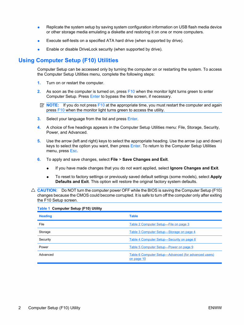
● Replicate the system setup by saving system configuration information on USB flash media deviceor other storage media emulating a diskette and restoring it on one or more computers.
● Execute self-tests on a specified ATA hard drive (when supported by drive).
● Enable or disable DriveLock security (when supported by drive).
Using Computer Setup (F10) UtilitiesComputer Setup can be accessed only by turning the computer on or restarting the system. To accessthe Computer Setup Utilities menu, complete the following steps:
1. Turn on or restart the computer.
2. As soon as the computer is turned on, press F10 when the monitor light turns green to enterComputer Setup. Press Enter to bypass the title screen, if necessary.
NOTE: If you do not press F10 at the appropriate time, you must restart the computer and againpress F10 when the monitor light turns green to access the utility.
3. Select your language from the list and press Enter.
4. A choice of five headings appears in the Computer Setup Utilities menu: File, Storage, Security,Power, and Advanced.
5. Use the arrow (left and right) keys to select the appropriate heading. Use the arrow (up and down)keys to select the option you want, then press Enter. To return to the Computer Setup Utilitiesmenu, press Esc.
6. To apply and save changes, select File > Save Changes and Exit.
● If you have made changes that you do not want applied, select Ignore Changes and Exit.
● To reset to factory settings or previously saved default settings (some models), select ApplyDefaults and Exit. This option will restore the original factory system defaults.
CAUTION: Do NOT turn the computer power OFF while the BIOS is saving the Computer Setup (F10)changes because the CMOS could become corrupted. It is safe to turn off the computer only after exitingthe F10 Setup screen.
Table 1 Computer Setup (F10) Utility
Heading Table
File Table 2 Computer Setup—File on page 3
Storage Table 3 Computer Setup—Storage on page 4
Security Table 4 Computer Setup—Security on page 6
Power Table 5 Computer Setup—Power on page 9
Advanced Table 6 Computer Setup—Advanced (for advanced users)on page 10
2 Computer Setup (F10) Utility ENWW
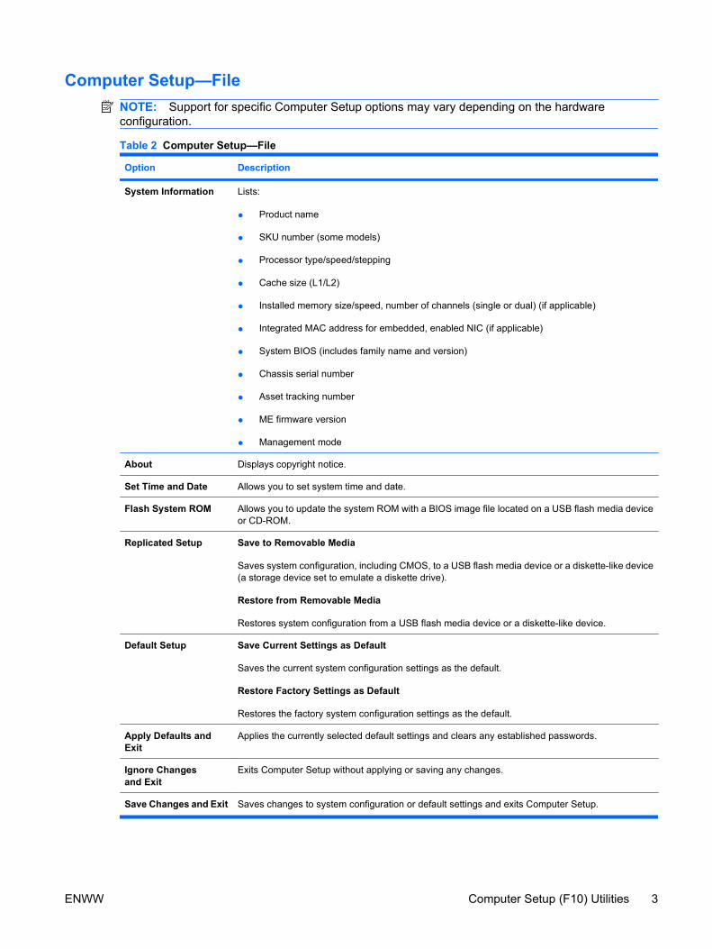
Computer Setup—FileNOTE: Support for specific Computer Setup options may vary depending on the hardwareconfiguration.
Table 2 Computer Setup—File
Option Description
System Information Lists:
● Product name
● SKU number (some models)
● Processor type/speed/stepping
● Cache size (L1/L2)
● Installed memory size/speed, number of channels (single or dual) (if applicable)
● Integrated MAC address for embedded, enabled NIC (if applicable)
● System BIOS (includes family name and version)
● Chassis serial number
● Asset tracking number
● ME firmware version
● Management mode
About Displays copyright notice.
Set Time and Date Allows you to set system time and date.
Flash System ROM Allows you to update the system ROM with a BIOS image file located on a USB flash media deviceor CD-ROM.
Replicated Setup Save to Removable Media
Saves system configuration, including CMOS, to a USB flash media device or a diskette-like device(a storage device set to emulate a diskette drive).
Restore from Removable Media
Restores system configuration from a USB flash media device or a diskette-like device.
Default Setup Save Current Settings as Default
Saves the current system configuration settings as the default.
Restore Factory Settings as Default
Restores the factory system configuration settings as the default.
Apply Defaults andExit
Applies the currently selected default settings and clears any established passwords.
Ignore Changesand Exit
Exits Computer Setup without applying or saving any changes.
Save Changes and Exit Saves changes to system configuration or default settings and exits Computer Setup.
ENWW Computer Setup (F10) Utilities 3
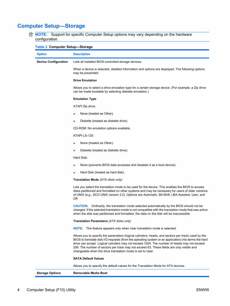
Computer Setup—StorageNOTE: Support for specific Computer Setup options may vary depending on the hardwareconfiguration.
Table 3 Computer Setup—Storage
Option Description
Device Configuration Lists all installed BIOS-controlled storage devices.
When a device is selected, detailed information and options are displayed. The following optionsmay be presented:
Drive Emulation
Allows you to select a drive emulation type for a certain storage device. (For example, a Zip drivecan be made bootable by selecting diskette emulation.)
Emulation Type
ATAPI Zip drive:
● None (treated as Other).
● Diskette (treated as diskette drive).
CD-ROM: No emulation options available.
ATAPI LS-120:
● None (treated as Other).
● Diskette (treated as diskette drive).
Hard Disk:
● None (prevents BIOS data accesses and disables it as a boot device).
● Hard Disk (treated as hard disk).
Translation Mode (ATA disks only)
Lets you select the translation mode to be used for the device. This enables the BIOS to accessdisks partitioned and formatted on other systems and may be necessary for users of older versionsof UNIX (e.g., SCO UNIX version 3.2). Options are Automatic, Bit-Shift, LBA Assisted, User, andOff.
CAUTION: Ordinarily, the translation mode selected automatically by the BIOS should not bechanged. If the selected translation mode is not compatible with the translation mode that was activewhen the disk was partitioned and formatted, the data on the disk will be inaccessible.
Translation Parameters (ATA disks only)
NOTE: This feature appears only when User translation mode is selected.
Allows you to specify the parameters (logical cylinders, heads, and sectors per track) used by theBIOS to translate disk I/O requests (from the operating system or an application) into terms the harddrive can accept. Logical cylinders may not exceed 1024. The number of heads may not exceed256. The number of sectors per track may not exceed 63. These fields are only visible andchangeable when the drive translation mode is set to User.
SATA Default Values
Allows you to specify the default values for the Translation Mode for ATA devices.
Storage Options Removable Media Boot
4 Computer Setup (F10) Utility ENWW
Option Description
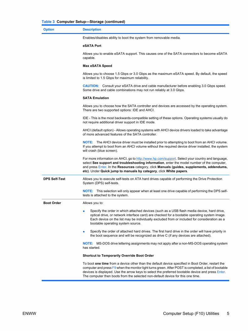
Enables/disables ability to boot the system from removable media.
eSATA Port
Allows you to enable eSATA support. This causes one of the SATA connectors to become eSATAcapable.
Max eSATA Speed
Allows you to choose 1.5 Gbps or 3.0 Gbps as the maximum eSATA speed. By default, the speedis limited to 1.5 Gbps for maximum reliability.
CAUTION: Consult your eSATA drive and cable manufacturer before enabling 3.0 Gbps speed.Some drive and cable combinations may not run reliably at 3.0 Gbps.
SATA Emulation
Allows you to choose how the SATA controller and devices are accessed by the operating system.There are two supported options: IDE and AHCI.
IDE - This is the most backwards-compatible setting of these options. Operating systems usually donot require additional driver support in IDE mode.
AHCI (default option) - Allows operating systems with AHCI device drivers loaded to take advantageof more advanced features of the SATA controller.
NOTE: The AHCI device driver must be installed prior to attempting to boot from an AHCI volume.If you attempt to boot from an AHCI volume without the required device driver installed, the systemwill crash (blue screen).
For more information on AHCI, go to http://www.hp.com/support. Select your country and language,select See support and troubleshooting information, enter the model number of the computer,and press Enter. In the Resources category, click Manuals (guides, supplements, addendums,etc). Under Quick jump to manuals by category, click White papers.
DPS Self-Test Allows you to execute self-tests on ATA hard drives capable of performing the Drive ProtectionSystem (DPS) self-tests.
NOTE: This selection will only appear when at least one drive capable of performing the DPS self-tests is attached to the system.
Boot Order Allows you to:
● Specify the order in which attached devices (such as a USB flash media device, hard drive,optical drive, or network interface card) are checked for a bootable operating system image.Each device on the list may be individually excluded from or included for consideration as abootable operating system source.
● Specify the order of attached hard drives. The first hard drive in the order will have priority inthe boot sequence and will be recognized as drive C (if any devices are attached).
NOTE: MS-DOS drive lettering assignments may not apply after a non-MS-DOS operating systemhas started.
Shortcut to Temporarily Override Boot Order
To boot one time from a device other than the default device specified in Boot Order, restart thecomputer and press F9 when the monitor light turns green. After POST is completed, a list of bootabledevices is displayed. Use the arrow keys to select the preferred bootable device and press Enter.The computer then boots from the selected non-default device for this one time.
Table 3 Computer Setup—Storage (continued)
ENWW Computer Setup (F10) Utilities 5
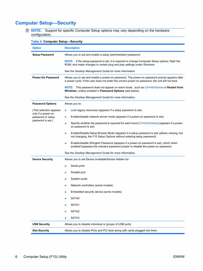
Computer Setup—SecurityNOTE: Support for specific Computer Setup options may vary depending on the hardwareconfiguration.
Table 4 Computer Setup—Security
Option Description
Setup Password Allows you to set and enable a setup (administrator) password.
NOTE: If the setup password is set, it is required to change Computer Setup options, flash theROM, and make changes to certain plug and play settings under Windows.
See the Desktop Management Guide for more information.
Power-On Password Allows you to set and enable a power-on password. The power-on password prompt appears aftera power cycle. If the user does not enter the correct power-on password, the unit will not boot.
NOTE: This password does not appear on warm boots , such as Ctrl+Alt+Delete or Restart fromWindows, unless enabled in Password Options (see below).
See the Desktop Management Guide for more information.
Password Options
(This selection appearsonly if a power-onpassword or setuppassword is set.)
Allows you to:
● Lock legacy resources (appears if a setup password is set)
● Enable/disable network server mode (appears if a power-on password is set)
● Specify whether the password is required for warm boot (Ctrl+Alt+Delete) (appears if a power-on password is set)
● Enable/Disable Setup Browse Mode (appears if a setup password is set) (allows viewing, butnot changing, the F10 Setup Options without entering setup password)
● Enable/disable Stringent Password (appears if a power-on password is set), which whenenabled bypasses the onboard password jumper to disable the power-on password.
See the Desktop Management Guide for more information.
Device Security Allows you to set Device Available/Device Hidden for:
● Serial ports
● Parallel port
● System audio
● Network controllers (some models)
● Embedded security device (some models)
● SATA0
● SATA1
● SATA2
● SATA3
USB Security Allows you to disable individual or groups of USB ports.
Slot Security Allows you to disable PCIe and PCI slots along with cards plugged into them.
6 Computer Setup (F10) Utility ENWW
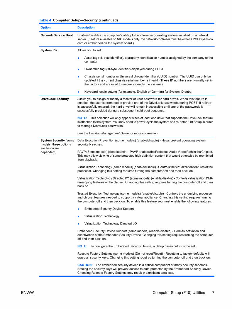
Option Description
Network Service Boot Enables/disables the computer’s ability to boot from an operating system installed on a networkserver. (Feature available on NIC models only; the network controller must be either a PCI expansioncard or embedded on the system board.)
System IDs Allows you to set:
● Asset tag (18-byte identifier), a property identification number assigned by the company to thecomputer.
● Ownership tag (80-byte identifier) displayed during POST.
● Chassis serial number or Universal Unique Identifier (UUID) number. The UUID can only beupdated if the current chassis serial number is invalid. (These ID numbers are normally set inthe factory and are used to uniquely identify the system.)
● Keyboard locale setting (for example, English or German) for System ID entry.
DriveLock Security Allows you to assign or modify a master or user password for hard drives. When this feature isenabled, the user is prompted to provide one of the DriveLock passwords during POST. If neitheris successfully entered, the hard drive will remain inaccessible until one of the passwords issuccessfully provided during a subsequent cold-boot sequence.
NOTE: This selection will only appear when at least one drive that supports the DriveLock featureis attached to the system. You may need to power-cycle the system and re-enter F10 Setup in orderto manage DriveLock passwords.
See the Desktop Management Guide for more information.
System Security (somemodels: these optionsare hardwaredependent)
Data Execution Prevention (some models) (enable/disable) - Helps prevent operating systemsecurity breaches.
PAVP (Some models) (disabled/min) - PAVP enables the Protected Audio Video Path in the Chipset.This may allow viewing of some protected high definition content that would otherwise be prohibitedfrom playback.
Virtualization Technology (some models) (enable/disable) - Controls the virtualization features of theprocessor. Changing this setting requires turning the computer off and then back on.
Virtualization Technology Directed I/O (some models) (enable/disable) - Controls virtualization DMAremapping features of the chipset. Changing this setting requires turning the computer off and thenback on.
Trusted Execution Technology (some models) (enable/disable) - Controls the underlying processorand chipset features needed to support a virtual appliance. Changing this setting requires turningthe computer off and then back on. To enable this feature you must enable the following features:
● Embedded Security Device Support
● Virtualization Technology
● Virtualization Technology Directed I/O
Embedded Security Device Support (some models) (enable/disable) - Permits activation anddeactivation of the Embedded Security Device. Changing this setting requires turning the computeroff and then back on.
NOTE: To configure the Embedded Security Device, a Setup password must be set.
Reset to Factory Settings (some models) (Do not reset/Reset) - Resetting to factory defaults willerase all security keys. Changing this setting requires turning the computer off and then back on.
CAUTION: The embedded security device is a critical component of many security schemes.Erasing the security keys will prevent access to data protected by the Embedded Security Device.Choosing Reset to Factory Settings may result in significant data loss.
Table 4 Computer Setup—Security (continued)
ENWW Computer Setup (F10) Utilities 7
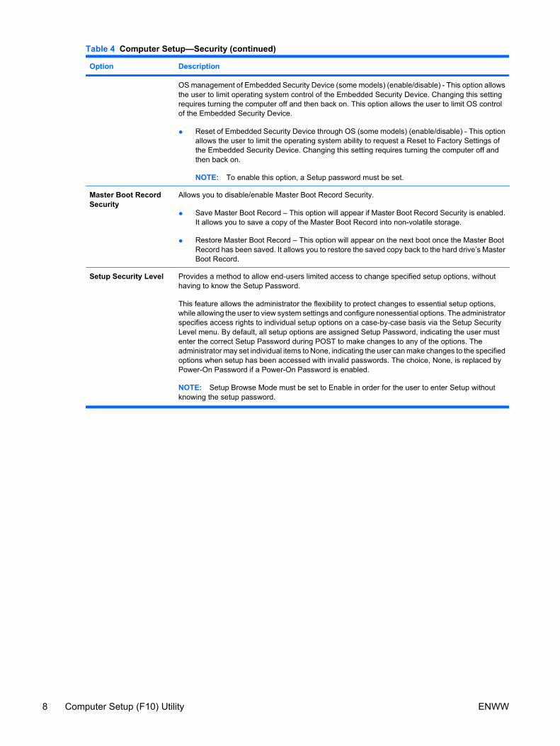
Option Description
OS management of Embedded Security Device (some models) (enable/disable) - This option allowsthe user to limit operating system control of the Embedded Security Device. Changing this settingrequires turning the computer off and then back on. This option allows the user to limit OS controlof the Embedded Security Device.
● Reset of Embedded Security Device through OS (some models) (enable/disable) - This optionallows the user to limit the operating system ability to request a Reset to Factory Settings ofthe Embedded Security Device. Changing this setting requires turning the computer off andthen back on.
NOTE: To enable this option, a Setup password must be set.
Master Boot RecordSecurity
Allows you to disable/enable Master Boot Record Security.
● Save Master Boot Record – This option will appear if Master Boot Record Security is enabled.It allows you to save a copy of the Master Boot Record into non-volatile storage.
● Restore Master Boot Record – This option will appear on the next boot once the Master BootRecord has been saved. It allows you to restore the saved copy back to the hard drive’s MasterBoot Record.
Setup Security Level Provides a method to allow end-users limited access to change specified setup options, withouthaving to know the Setup Password.
This feature allows the administrator the flexibility to protect changes to essential setup options,while allowing the user to view system settings and configure nonessential options. The administratorspecifies access rights to individual setup options on a case-by-case basis via the Setup SecurityLevel menu. By default, all setup options are assigned Setup Password, indicating the user mustenter the correct Setup Password during POST to make changes to any of the options. Theadministrator may set individual items to None, indicating the user can make changes to the specifiedoptions when setup has been accessed with invalid passwords. The choice, None, is replaced byPower-On Password if a Power-On Password is enabled.
NOTE: Setup Browse Mode must be set to Enable in order for the user to enter Setup withoutknowing the setup password.
Table 4 Computer Setup—Security (continued)
8 Computer Setup (F10) Utility ENWW
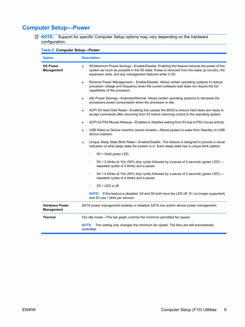
Computer Setup—PowerNOTE: Support for specific Computer Setup options may vary depending on the hardwareconfiguration.
Table 5 Computer Setup—Power
Option Description
OS PowerManagement
● S5 Maximum Power Savings—Enable/Disable. Enabling this feature reduces the power of thissystem as much as possible in the S5 state. Power is removed from the wake up circuitry, theexpansion slots, and any management features while in S5.
● Runtime Power Management— Enable/Disable. Allows certain operating systems to reduceprocessor voltage and frequency when the current software load does not require the fullcapabilities of the processor.
● Idle Power Savings—Extended/Normal. Allows certain operating systems to decrease theprocessors power consumption when the processor is idle.
● ACPI S3 Hard Disk Reset—Enabling this causes the BIOS to ensure hard disks are ready toaccept commands after resuming from S3 before returning control to the operating system.
● ACPI S3 PS2 Mouse Wakeup—Enables or disables waking from S3 due to PS2 mouse activity.
● USB Wake on Device Insertion (some models)—Allows system to wake from Standby on USBdevice insertion.
● Unique Sleep State Blink Rates—Enable/Disable. This feature is designed to provide a visualindication of what sleep state the system is in. Each sleep state has a unique blink pattern.
◦ S0 = Solid green LED.
◦ S3 = 3 blinks at 1Hz (50% duty cycle) followed by a pause of 2 seconds (green LED) —repeated cycles of 3 blinks and a pause.
◦ S4 = 4 blinks at 1Hz (50% duty cycle) followed by a pause of 2 seconds (green LED) —repeated cycles of 4 blinks and a pause.
◦ S5 = LED is off.
NOTE: If this feature is disabled, S4 and S5 both have the LED off. S1 (no longer supported)and S3 use 1 blink per second.
Hardware PowerManagement
SATA power management enables or disables SATA bus and/or device power management.
Thermal Fan idle mode—This bar graph controls the minimum permitted fan speed.
NOTE: This setting only changes the minimum fan speed. The fans are still automaticallycontrolled.
ENWW Computer Setup (F10) Utilities 9
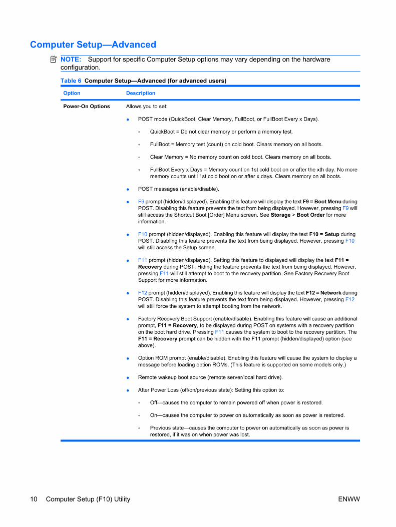
Computer Setup—AdvancedNOTE: Support for specific Computer Setup options may vary depending on the hardwareconfiguration.
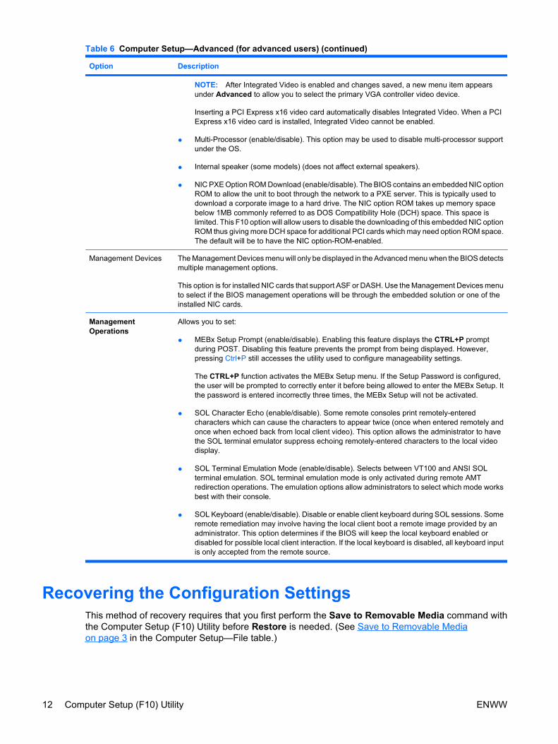
Table 6 Computer Setup—Advanced (for advanced users)
Option Description
Power-On Options Allows you to set:
● POST mode (QuickBoot, Clear Memory, FullBoot, or FullBoot Every x Days).
◦ QuickBoot = Do not clear memory or perform a memory test.
◦ FullBoot = Memory test (count) on cold boot. Clears memory on all boots.
◦ Clear Memory = No memory count on cold boot. Clears memory on all boots.
◦ FullBoot Every x Days = Memory count on 1st cold boot on or after the xth day. No morememory counts until 1st cold boot on or after x days. Clears memory on all boots.
● POST messages (enable/disable).
● F9 prompt (hidden/displayed). Enabling this feature will display the text F9 = Boot Menu duringPOST. Disabling this feature prevents the text from being displayed. However, pressing F9 willstill access the Shortcut Boot [Order] Menu screen. See Storage > Boot Order for moreinformation.
● F10 prompt (hidden/displayed). Enabling this feature will display the text F10 = Setup duringPOST. Disabling this feature prevents the text from being displayed. However, pressing F10will still access the Setup screen.
● F11 prompt (hidden/displayed). Setting this feature to displayed will display the text F11 =Recovery during POST. Hiding the feature prevents the text from being displayed. However,pressing F11 will still attempt to boot to the recovery partition. See Factory Recovery BootSupport for more information.
● F12 prompt (hidden/displayed). Enabling this feature will display the text F12 = Network duringPOST. Disabling this feature prevents the text from being displayed. However, pressing F12will still force the system to attempt booting from the network.
● Factory Recovery Boot Support (enable/disable). Enabling this feature will cause an additionalprompt, F11 = Recovery, to be displayed during POST on systems with a recovery partitionon the boot hard drive. Pressing F11 causes the system to boot to the recovery partition. TheF11 = Recovery prompt can be hidden with the F11 prompt (hidden/displayed) option (seeabove).
● Option ROM prompt (enable/disable). Enabling this feature will cause the system to display amessage before loading option ROMs. (This feature is supported on some models only.)
● Remote wakeup boot source (remote server/local hard drive).
● After Power Loss (off/on/previous state): Setting this option to:
◦ Off—causes the computer to remain powered off when power is restored.
◦ On—causes the computer to power on automatically as soon as power is restored.
◦ Previous state—causes the computer to power on automatically as soon as power isrestored, if it was on when power was lost.
10 Computer Setup (F10) Utility ENWW
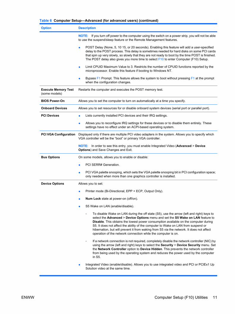
Option Description
NOTE: If you turn off power to the computer using the switch on a power strip, you will not be ableto use the suspend/sleep feature or the Remote Management features.
● POST Delay (None, 5, 10 15, or 20 seconds). Enabling this feature will add a user-specifieddelay to the POST process. This delay is sometimes needed for hard disks on some PCI cardsthat spin up very slowly, so slowly that they are not ready to boot by the time POST is finished.The POST delay also gives you more time to select F10 to enter Computer (F10) Setup.
● Limit CPUID Maximum Value to 3. Restricts the number of CPUID functions reported by themicroprocessor. Enable this feature if booting to Windows NT.
● Bypass F1 Prompt. This feature allows the system to boot without pressing F1 at the promptwhen the configuration changes.
Execute Memory Test(some models)
Restarts the computer and executes the POST memory test.
BIOS Power-On Allows you to set the computer to turn on automatically at a time you specify.
Onboard Devices Allows you to set resources for or disable onboard system devices (serial port or parallel port).
PCI Devices ● Lists currently installed PCI devices and their IRQ settings.
● Allows you to reconfigure IRQ settings for these devices or to disable them entirely. Thesesettings have no effect under an ACPI-based operating system.
PCI VGA Configuration Displayed only if there are multiple PCI video adapters in the system. Allows you to specify whichVGA controller will be the “boot” or primary VGA controller.
NOTE: In order to see this entry, you must enable Integrated Video (Advanced > DeviceOptions) and Save Changes and Exit.
Bus Options On some models, allows you to enable or disable:
● PCI SERR# Generation.
● PCI VGA palette snooping, which sets the VGA palette snooping bit in PCI configuration space;only needed when more than one graphics controller is installed.
Device Options Allows you to set:
● Printer mode (Bi-Directional, EPP + ECP, Output Only).
● Num Lock state at power-on (off/on).
● S5 Wake on LAN (enable/disable).
◦ To disable Wake on LAN during the off state (S5), use the arrow (left and right) keys toselect the Advanced > Device Options menu and set the S5 Wake on LAN feature toDisable. This obtains the lowest power consumption available on the computer duringS5. It does not affect the ability of the computer to Wake on LAN from suspend orhibernation, but will prevent it from waking from S5 via the network. It does not affectoperation of the network connection while the computer is on.
◦ If a network connection is not required, completely disable the network controller (NIC) byusing the arrow (left and right) keys to select the Security > Device Security menu. Setthe Network Controller option to Device Hidden. This prevents the network controllerfrom being used by the operating system and reduces the power used by the computerin S5.
● Integrated Video (enable/disable). Allows you to use integrated video and PCI or PCIEx1 UpSolution video at the same time.
Table 6 Computer Setup—Advanced (for advanced users) (continued)
ENWW Computer Setup (F10) Utilities 11
Option Description
NOTE: After Integrated Video is enabled and changes saved, a new menu item appearsunder Advanced to allow you to select the primary VGA controller video device.
Inserting a PCI Express x16 video card automatically disables Integrated Video. When a PCIExpress x16 video card is installed, Integrated Video cannot be enabled.
● Multi-Processor (enable/disable). This option may be used to disable multi-processor supportunder the OS.
● Internal speaker (some models) (does not affect external speakers).
● NIC PXE Option ROM Download (enable/disable). The BIOS contains an embedded NIC optionROM to allow the unit to boot through the network to a PXE server. This is typically used todownload a corporate image to a hard drive. The NIC option ROM takes up memory spacebelow 1MB commonly referred to as DOS Compatibility Hole (DCH) space. This space islimited. This F10 option will allow users to disable the downloading of this embedded NIC optionROM thus giving more DCH space for additional PCI cards which may need option ROM space.The default will be to have the NIC option-ROM-enabled.
Management Devices The Management Devices menu will only be displayed in the Advanced menu when the BIOS detectsmultiple management options.
This option is for installed NIC cards that support ASF or DASH. Use the Management Devices menuto select if the BIOS management operations will be through the embedded solution or one of theinstalled NIC cards.
ManagementOperations
Allows you to set:
● MEBx Setup Prompt (enable/disable). Enabling this feature displays the CTRL+P promptduring POST. Disabling this feature prevents the prompt from being displayed. However,pressing Ctrl+P still accesses the utility used to configure manageability settings.
The CTRL+P function activates the MEBx Setup menu. If the Setup Password is configured,the user will be prompted to correctly enter it before being allowed to enter the MEBx Setup. Itthe password is entered incorrectly three times, the MEBx Setup will not be activated.
● SOL Character Echo (enable/disable). Some remote consoles print remotely-enteredcharacters which can cause the characters to appear twice (once when entered remotely andonce when echoed back from local client video). This option allows the administrator to havethe SOL terminal emulator suppress echoing remotely-entered characters to the local videodisplay.
● SOL Terminal Emulation Mode (enable/disable). Selects between VT100 and ANSI SOLterminal emulation. SOL terminal emulation mode is only activated during remote AMTredirection operations. The emulation options allow administrators to select which mode worksbest with their console.
● SOL Keyboard (enable/disable). Disable or enable client keyboard during SOL sessions. Someremote remediation may involve having the local client boot a remote image provided by anadministrator. This option determines if the BIOS will keep the local keyboard enabled ordisabled for possible local client interaction. If the local keyboard is disabled, all keyboard inputis only accepted from the remote source.
Recovering the Configuration SettingsThis method of recovery requires that you first perform the Save to Removable Media command withthe Computer Setup (F10) Utility before Restore is needed. (See Save to Removable Mediaon page 3 in the Computer Setup—File table.)
Table 6 Computer Setup—Advanced (for advanced users) (continued)
12 Computer Setup (F10) Utility ENWW

NOTE: It is recommended that you save any modified computer configuration settings to a a USBflash media device or a diskette-like device (a storage device set to emulate a diskette drive) and savethe device for possible future use.
To restore the configuration, insert a USB flash media device or other storage media emulating a diskettewith the saved configuration and perform the Restore from Removable Media command with theComputer Setup (F10) Utility. (See Restore from Removable Media on page 3 in the Computer Setup—File table.)
ENWW Recovering the Configuration Settings 13