Embed Size (px)
Citation preview
Computer simulation of an F-4 Phantom crashing into a reinforced concrete wall
M. Itoh1, M. Katayama1 & R. Rainsberger2 1CRC Solution Corp., Japan 2XYZ Scientific Applications Inc., U.S.A.
Abstract
This paper presents a numerical simulation of an aircraft crashing into a reinforced concrete wall by using a general-purpose hydrocode AUTODYN®. Computational results are compared with the experimental ones obtained by a full-scale aircraft impact test conducted at Sandia National Laboratories in New Mexico, USA, in 1988. An actual F-4 Phantom jetfighter was used in the test. The geometry of the finite element model of the aircraft is adjusted to fit to the data given in the test report and also available publicly. Two engines, a fuel tank, and water to simulate the fuel weight are considered in the numerical model. The numerical results show good agreements with the experimental ones as to an impact force, damage to the wall and the crushing behaviour of the aircraft. Keywords: numerical simulation, aircraft impact, F-4 phantom, reinforced concrete, hydrocode, AUTODYN®, impact force, finite element.
1 Introduction
An aircraft generally consists of many components such as a fuselage, main wings, tail wings, engines, landing gears, avionics equipments, ribs/stringers, seats, fuel tanks with fuel inside, and so forth. To take every component into account in a numerical model requires a lot of human resources in addition to increasing loads on a computing capacity, because it is not an easy task in most cases to obtain detailed data on the geometrical arrangements of these parts especially of a military aircraft.
In this study we propose a finite element model which is reasonably simple and accurate enough to simulate the impact of an aircraft on a deformable target.
© 2005 WIT Press WIT Transactions on Modelling and Simulation, Vol 40, www.witpress.com, ISSN 1743-355X (on-line)
Computational Ballistics II 207
The fundamental idea is to consider only major components having large masses like a fuselage, wings, engines and fuel. They are modelled so that their shapes and sizes are in agreement with the ones of actual aircrafts. The masses of other remaining components are distributed uniformly to the fuselage and the wings. As for the constitutive model the strain hardening and the strain rate effects are considered because of the highly nonlinear characteristics of the impact phenomena.
We verify the applicability and the accuracy of the model by comparing numerical results with experimental ones. The impact test we selected for this purpose is the one performed by Sandia National Laboratories under terms of a contract with the Muto Institute of Structural Mechanics, Inc., of Tokyo [1, 2, 4]. The test yielded an extensive set of response data, of which we focus on the following major measurements,
1) Crushing behaviour of the F-4, 2) Impact force loaded on the target, 3) Damage to the concrete.
Recommendations for future studies are also presented to improve the accuracy of the proposed model.
2 Full-scale aircraft impact test
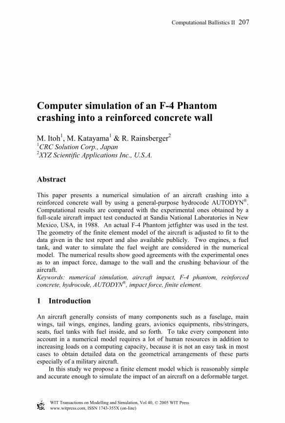
Before describing the numerical simulation we briefly summarize the impact test. The primary purpose of the test was aimed at determining the impact force as a function of time when an F-4 Phantom impacts onto a massive, essentially rigid, reinforced concrete. Fig.1 is the moment photograph of the impact.
Figure 1: The moment photograph of the F-4 impacting the target.
© 2005 WIT Press WIT Transactions on Modelling and Simulation, Vol 40, www.witpress.com, ISSN 1743-355X (on-line)
208 Computational Ballistics II
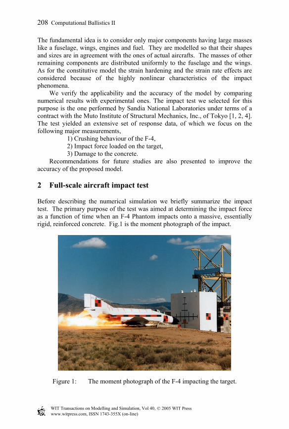
The test configuration of the F-4 is shown in Fig.2. The front and the main landing gears were removed. Instead a sled with a carriage structure was attached on the under surface of the aircraft. The sled was mounted on two rails of 600 meter long which guided the F-4, accelerated by rockets, to the target. The impact speed was 215 m/s.
The total impact weight was 19 tonnes comprising 12.7 tonnes of the F-4, 1.5 tonnes of the sled and the carriage, 4.8 tonnes of water which is used to simulate the weight of fuel. The weight specification is listed in Table 1.
The target was a rectangular block of reinforced concrete 7 meter square and 3.66 meter thick which weighs 469 tonnes (i.e. approximately 25 times heavier than the F-4). It was placed on an air-bearing platform which enabled almost free movement in the direction of impact.
Figure 2: Test configuration of F-4 Phantom.
11.71
m
Pusher Sled with 36Super Zuni Rockets
CarriageSupport
Nike Rockets(Total 5)
J 12 J 14 J 10 J 4J 8 J 7 J 6 J 9 J 5 J 1
Water Brake Carriage Shoes
5.02
m
17.74 m
J 11J 13
© 2005 WIT Press WIT Transactions on Modelling and Simulation, Vol 40, www.witpress.com, ISSN 1743-355X (on-line)
Computational Ballistics II 209
3 Finite element model
3.1 F-4 phantom
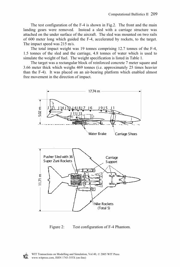
The geometry of the fuselage of the F-4 Phantom is created first by the general-purpose mesh generation computer program TrueGrid [5]. Then the obtained geometry is imported into the finite element model of the AUTODYN® [6] as shown in Fig.3. The size of the F-4 is adjusted to fit to the configurations shown in Fig.2.
Because of the intense impact loading condition a constitutive model for the material of the aircraft is required to consider the strain hardening and the strain rate effects. The Johnson-Cook model is adopted and the material properties of the 2024-T351 aluminium are taken from [7]. The material properties of Glass-Epoxy for the windshield are taken from the material library of AUTODYN®.
Figure 3: Finite element model of an F-4 Phantom, a total of 58,800 elements
including two engines and water inside a fuel tank
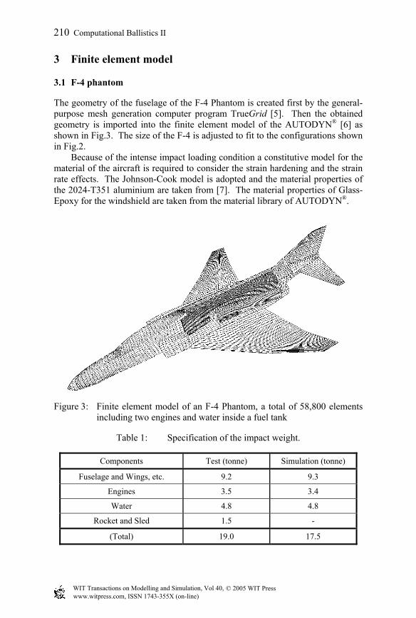
Table 1: Specification of the impact weight.
Components Test (tonne) Simulation (tonne)
Fuselage and Wings, etc. 9.2 9.3
Engines 3.5 3.4
Water 4.8 4.8
Rocket and Sled 1.5 -
(Total) 19.0 17.5
© 2005 WIT Press WIT Transactions on Modelling and Simulation, Vol 40, www.witpress.com, ISSN 1743-355X (on-line)
210 Computational Ballistics II
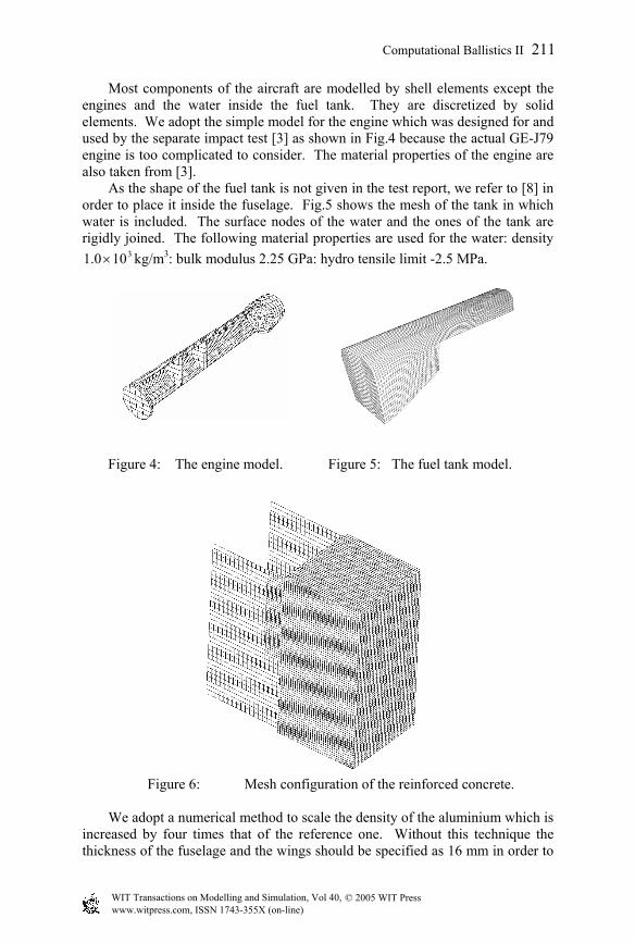
Most components of the aircraft are modelled by shell elements except the engines and the water inside the fuel tank. They are discretized by solid elements. We adopt the simple model for the engine which was designed for and used by the separate impact test [3] as shown in Fig.4 because the actual GE-J79 engine is too complicated to consider. The material properties of the engine are also taken from [3].
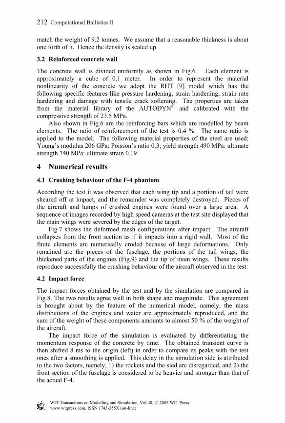
As the shape of the fuel tank is not given in the test report, we refer to [8] in order to place it inside the fuselage. Fig.5 shows the mesh of the tank in which water is included. The surface nodes of the water and the ones of the tank are rigidly joined. The following material properties are used for the water: density
3100.1 × kg/m3: bulk modulus 2.25 GPa: hydro tensile limit -2.5 MPa.
Figure 4: The engine model. Figure 5: The fuel tank model.
Figure 6: Mesh configuration of the reinforced concrete. We adopt a numerical method to scale the density of the aluminium which is
increased by four times that of the reference one. Without this technique the thickness of the fuselage and the wings should be specified as 16 mm in order to
© 2005 WIT Press WIT Transactions on Modelling and Simulation, Vol 40, www.witpress.com, ISSN 1743-355X (on-line)
Computational Ballistics II 211
match the weight of 9.2 tonnes. We assume that a reasonable thickness is about one forth of it. Hence the density is scaled up.
3.2 Reinforced concrete wall
The concrete wall is divided uniformly as shown in Fig.6. Each element is approximately a cube of 0.1 meter. In order to represent the material nonlinearity of the concrete we adopt the RHT [9] model which has the following specific features like pressure hardening, strain hardening, strain rate hardening and damage with tensile crack softening. The properties are taken from the material library of the AUTODYN® and calibrated with the compressive strength of 23.5 MPa.
Also shown in Fig.6 are the reinforcing bars which are modelled by beam elements. The ratio of reinforcement of the test is 0.4 %. The same ratio is applied to the model. The following material properties of the steel are used: Young’s modulus 206 GPa: Poisson’s ratio 0.3; yield strength 490 MPa: ultimate strength 740 MPa: ultimate strain 0.19.
4 Numerical results
4.1 Crushing behaviour of the F-4 phantom
According the test it was observed that each wing tip and a portion of tail were sheared off at impact, and the remainder was completely destroyed. Pieces of the aircraft and lumps of crushed engines were found over a large area. A sequence of images recorded by high speed cameras at the test site displayed that the main wings were severed by the edges of the target.
Fig.7 shows the deformed mesh configurations after impact. The aircraft collapses from the front section as if it impacts into a rigid wall. Most of the finite elements are numerically eroded because of large deformations. Only remained are the pieces of the fuselage, the portions of the tail wings, the thickened parts of the engines (Fig.9) and the tip of main wings. These results reproduce successfully the crushing behaviour of the aircraft observed in the test.
4.2 Impact force
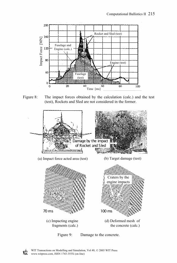
The impact forces obtained by the test and by the simulation are compared in Fig.8. The two results agree well in both shape and magnitude. This agreement is brought about by the feature of the numerical model, namely, the mass distributions of the engines and water are approximately reproduced, and the sum of the weight of these components amounts to almost 50 % of the weight of the aircraft.
The impact force of the simulation is evaluated by differentiating the momentum response of the concrete by time. The obtained transient curve is then shifted 8 ms to the origin (left) in order to compare its peaks with the test ones after a smoothing is applied. This delay in the simulation side is attributed to the two factors, namely, 1) the rockets and the sled are disregarded, and 2) the front section of the fuselage is considered to be heavier and stronger than that of the actual F-4.
© 2005 WIT Press WIT Transactions on Modelling and Simulation, Vol 40, www.witpress.com, ISSN 1743-355X (on-line)
212 Computational Ballistics II
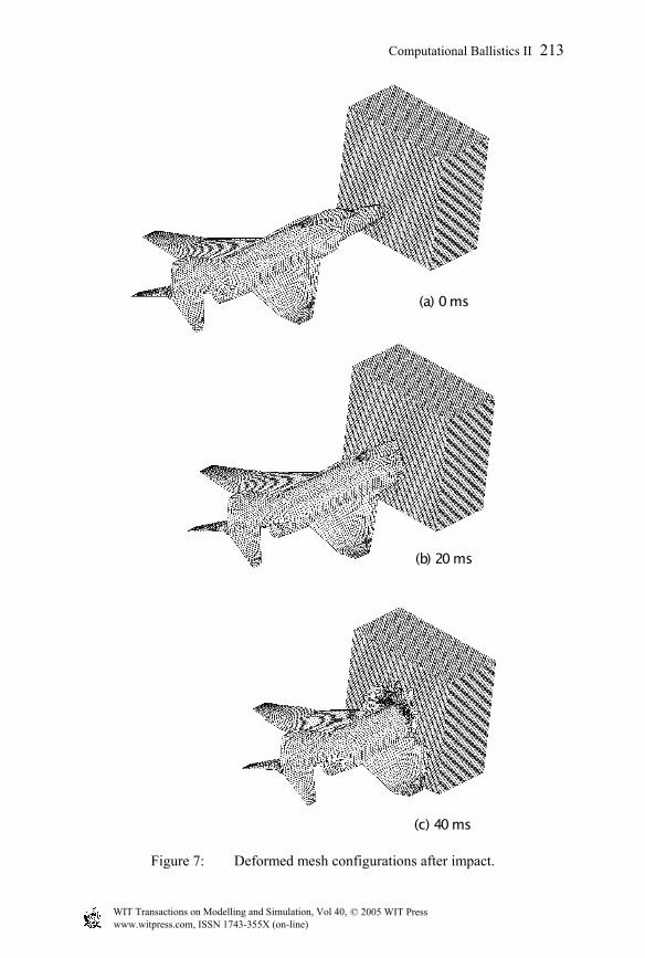
Figure 7: Deformed mesh configurations after impact.
(a) 0 ms
(b) 20 ms
(c) 40 ms
© 2005 WIT Press WIT Transactions on Modelling and Simulation, Vol 40, www.witpress.com, ISSN 1743-355X (on-line)
Computational Ballistics II 213
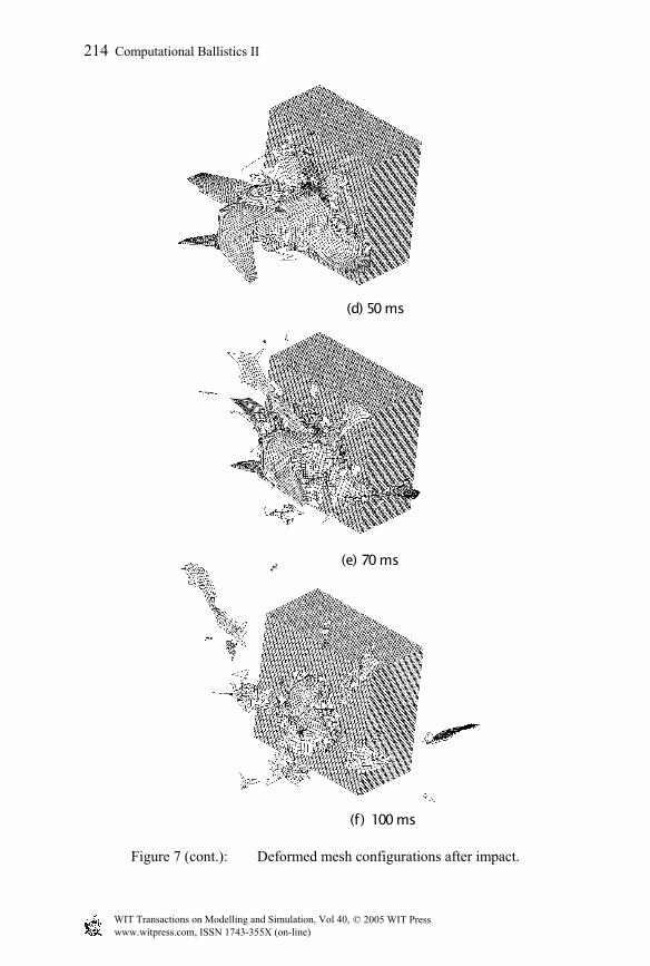
Figure 7 (cont.): Deformed mesh configurations after impact.
(d) 50 ms
(e) 70 ms
(f ) 100 ms
© 2005 WIT Press WIT Transactions on Modelling and Simulation, Vol 40, www.witpress.com, ISSN 1743-355X (on-line)
214 Computational Ballistics II
Engine (test)
Rocket and Sled (test)
Fuselage(test)
Fuselage andEngine (calc.)
Time [ms]
Impa
ct F
orce
[M
N]
Figure 8: The impact forces obtained by the calculation (calc.) and the test (test), Rockets and Sled are not considered in the former.
of Rocket and Sled
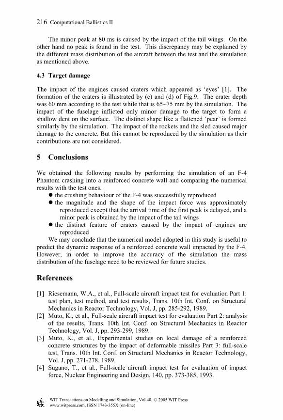
(a) Impact force acted area (test)
(c) Impacting engine fragments (calc.)
(d) Deformed mesh of the concrete (calc.)
Craters by theengine impacts
100 ms
Figure 9: Damage to the concrete.
(b) Target damage (test)
Damage by the impact
70 ms
© 2005 WIT Press WIT Transactions on Modelling and Simulation, Vol 40, www.witpress.com, ISSN 1743-355X (on-line)
Computational Ballistics II 215
The minor peak at 80 ms is caused by the impact of the tail wings. On the other hand no peak is found in the test. This discrepancy may be explained by the different mass distribution of the aircraft between the test and the simulation as mentioned above.
4.3 Target damage
The impact of the engines caused craters which appeared as ‘eyes’ [1]. The formation of the craters is illustrated by (c) and (d) of Fig.9. The crater depth was 60 mm according to the test while that is 65~75 mm by the simulation. The impact of the fuselage inflicted only minor damage to the target to form a shallow dent on the surface. The distinct shape like a flattened ‘pear’ is formed similarly by the simulation. The impact of the rockets and the sled caused major damage to the concrete. But this cannot be reproduced by the simulation as their contributions are not considered.
5 Conclusions
We obtained the following results by performing the simulation of an F-4 Phantom crashing into a reinforced concrete wall and comparing the numerical results with the test ones.
the crushing behaviour of the F-4 was successfully reproduced the magnitude and the shape of the impact force was approximately
reproduced except that the arrival time of the first peak is delayed, and a minor peak is obtained by the impact of the tail wings
the distinct feature of craters caused by the impact of engines are reproduced
We may conclude that the numerical model adopted in this study is useful to predict the dynamic response of a reinforced concrete wall impacted by the F-4. However, in order to improve the accuracy of the simulation the mass distribution of the fuselage need to be reviewed for future studies.
References
[1] Riesemann, W.A., et al., Full-scale aircraft impact test for evaluation Part 1: test plan, test method, and test results, Trans. 10th Int. Conf. on Structural Mechanics in Reactor Technology, Vol. J, pp. 285-292, 1989.
[2] Muto, K., et al., Full-scale aircraft impact test for evaluation Part 2: analysis of the results, Trans. 10th Int. Conf. on Structural Mechanics in Reactor Technology, Vol. J, pp. 293-299, 1989.
[3] Muto, K., et al., Experimental studies on local damage of a reinforced concrete structures by the impact of deformable missiles Part 3: full-scale test, Trans. 10th Int. Conf. on Structural Mechanics in Reactor Technology, Vol. J, pp. 271-278, 1989.
[4] Sugano, T., et al., Full-scale aircraft impact test for evaluation of impact force, Nuclear Engineering and Design, 140, pp. 373-385, 1993.
© 2005 WIT Press WIT Transactions on Modelling and Simulation, Vol 40, www.witpress.com, ISSN 1743-355X (on-line)
216 Computational Ballistics II
[5] TrueGrid User Manual Version 2.1, XYZ Scientific Applications, 2001. [6] AUTODYN Theory Manual, Century Dynamics, 2001. [7] Johnson, G.R. and Cook, W.H., A constitutive model and data for materials
subjected to large strain, high strain rates, and high temperatures, Proc. Int. Sympo. Ballistics, pp. 541-547, 1983.
[8] Famous airplanes of the world, No.23 (in Japanese), Bunrin-do, Tokyo, 1972.
[9] Reidel, W., et al., Penetration of reinforced concrete by BETA-B-500, numerical analysis using a new macroscopic concrete model for hydrocodes, 9th Int. Sympo., Interaction of the Effects of Motions with Structures, 1999.
© 2005 WIT Press WIT Transactions on Modelling and Simulation, Vol 40, www.witpress.com, ISSN 1743-355X (on-line)
Computational Ballistics II 217