Embed Size (px)
Citation preview
Louisiana State UniversityLSU Digital Commons
LSU Historical Dissertations and Theses Graduate School
1987
Computer Simulation of Hydrostatic Co-Extrusionof Bimetallic Compounds.Mohammad Mohammad abadi DehghaniLouisiana State University and Agricultural & Mechanical College
Follow this and additional works at: https://digitalcommons.lsu.edu/gradschool_disstheses
This Dissertation is brought to you for free and open access by the Graduate School at LSU Digital Commons. It has been accepted for inclusion inLSU Historical Dissertations and Theses by an authorized administrator of LSU Digital Commons. For more information, please [email protected].
Recommended CitationDehghani, Mohammad Mohammad abadi, "Computer Simulation of Hydrostatic Co-Extrusion of Bimetallic Compounds." (1987).LSU Historical Dissertations and Theses. 4444.https://digitalcommons.lsu.edu/gradschool_disstheses/4444
INFORMATION TO USERS
The most advanced technology has been used to photograph and reproduce this manuscript from the microfilm master. UMI films the original text directly from the copy submitted. Thus, some dissertation copies are in typewriter face, while others may be from a computer printer.
In the unlikely event that the author did not send UMI a complete manuscript and there are missing pages, these will be noted. Also, if unauthorized copyrighted material had to be removed, a note will indicate the deletion.
Oversize m aterials (e.g., maps, drawings, charts) are reproduced by sectioning the original, beginning at the upper left-hand comer and continuing from left to right in equal sections with small overlaps. Each oversize page is available as one exposure on a standard 35 mm slide or as a 17" x 23" black and white photographic print for an additional charge.
Photographs included in the original manuscript have been reproduced xerographically in this copy. 35 mm slides or 6" x 9" black and white photographic prints are available for any photographs or illustrations appearing in this copy for an additional charge. Contact UMI directly to order.
UMIA c c e ss in g th e World's Information s in c e 1938
3 0 0 North Z eeb Road, Ann Arbor, Ml 48106-1346 USA

O rder N u m b er 8811402
C om puter sim ulation o f hydrostatic co-extrusion o f b im etallic com pounds
Dehghani, Mohammad Mohammad Abadi, Ph.D.
The Louisiana State University and Agricultural and Mechanical Col., 1987
U M I300 N. ZeebRd.Ann Arbor, MI 48106


PLEASE NOTE:
In all c a se s th is m aterial h a s been film ed in th e b es t possib le w ay from th e available copy. Problem s en co u n te red with this d o cu m en t have been identified here with a c h eck mark V .
1. G lossy p h o to g rap h s or p a g e s ______
2. Colored illustrations, paper o r p r in t_______
3. Photographs with dark b a c k g ro u n d _____
4. Illustrations a re p o o r c o p y _______
5. P ag es with b lack m arks, not original c o p y ______
6. Print show s th ro u g h a s th ere is tex t on both sides of p a g e ________
7. Indistinct, broken o r small print on several pages l /
8. Print ex ceed s m arg in re q u ire m e n ts______
9. Tightly bound c o p y with print lo st in s p in e ________
10. C om puter p rin tou t p ag es with indistinct p rin t_______
11. P a g e (s )_____________ lacking w hen m aterial received, a n d not available from schoo l o rauthor.
12. P a g e (s )_____________ seem to b e m issing in num bering only as text follows.
13. Two p ag es n u m b e re d . Text follows.
14. Curling and w rinkled p a g e s _______
15. Dissertation c o n ta in s p ag es w ith print a t a slant, filmed a s received__________
16. O ther_______________________________________________________________________________
UMI

COMPUTER SIMULATION OF HYDROSTATIC CO-EXTRUSION OF BIMETALLIC COMPOUNDS
A Disser ta t ion
Submitted to the Graduate Faculty of the Louisiana Sta te University and
Agricultura l and Mechanical College in p a r t i a l f u l f i l lm e n t of the
requirements fo r the degree of Doctor of Philosophy
in
The Department of Mechanical Engineering
byMohammad M. Dehghani
B.S.M.E., Louisiana S ta te Univers ity , 1980 M.S.M.E., Louisiana S ta te Univers ity , 1982
December, 1987
ACKLOWLEDGMENTS
I would l ik e to express my s incere apprecia t ion to my major
p ro fesso r , Dr. Craig S. Hart ley , fo r his invaluable advice, d i r e c t io n ,
and encouragement in the course of t h i s research. His support was
u nfa i l ing and endured throughout t h i s work, even in his absence.
For consu l ta t ion and help on various aspects of t h i s work, I am
g ra te fu l to the members o f my committee, namely Dr. Mehdi Sabbaghian,
Dr. George Voyajis, and Dr. Haravi11 Eaton.
I a l so would l ike to extend my g ra t i tu d e to those i n s t i t u t i o n s
which have contr ibuted in d i f f e r e n t ways to t h i s study: to the s t a f f
and fellow s tudents of the Mechanical Engineering Department a t
Louisiana S ta te Univers ity fo r providing the opportunity and the
environment necessary fo r t h i s work; to the Westinghouse Laboratories
fo r providing the ex trus ion press and the extruded m a te r ia l s ; to the
United Sta tes Air Force Material Laboratories fo r the a ss is tance in
preparing the t e s t m a te r i a l s ; and to the Louisiana Department of
Transporta tion and Development fo r provision of the computational
equipment, without which the completion of t h i s work was in jeopardy.
For valuable suggestions and co n tac t s , I am indebted to Professor
Raghu Sirtenvasson of Wright S ta te Univers i ty , to Dr. Man. Iyer of
Westinghouse Labora tor ies , and to Dr. Ramzy Adams of the Louisiana
Department o f Transporta tion and Development.
My f u r th e r thanks go to Mrs. Dot S te r l in g of the Computer Division
of the Louisiana Department of Transporta tion and Development fo r her
devoted and e f f e c t iv e a ss i s tance whenever needed and fo r her enduring
pa tience .
F ina l ly , the whole owes i t s coherent exis tence to Ms. Libbye
Morris, who kept track of a stream of disconnected material and buttoned
up the loose ends. She i s a lso the r e c ip ien t of the c r e d i t fo r ed i t ing
and typing the e n t i r e manuscript .
TABLE OF CONTENTS
Page
Acknowledgments ..................................................................................................... i i
L i s t of T a b l e s ........................................................................................................ v i i
L is t of F i g u r e s .........................................................................................................v i i i
A b s t r a c t ...................................................................................................................... x i i
CHAPTER 1 - INTRODUCTION .................................................................................... 1
1.1 General Pr inc ip les ................................................................................... 1
1.1.1 The Extrusion Process ............................................................... 11.1 .2 H is to r ica l Development ............................................................... 31.1 .3 Comparison with Other Deformation Processes .................... 10
1.2 Types of E x t r u s i o n ................................................................................... 14
1.2.1 Direct Extrusion ............................................................................ 151.2 .2 Ind i rec t Extrusion ........................................................................ 171.2 .3 Hydrostat ic Extrusion ............................................................... 20
1 .2 .3 .1 Method of Operation ................................................... 211 .2 .3 .2 Simple Hydrostatic Extrusion .............................. 231 .2 .3 .3 F lu id - to -F lu id Hydrostatic Extrusion . . . . 241 .2 .3 .4 Augmented Hydrostatic Extrusion ............................ 251 .2 .3 .5 Continuous and Semicontinuous
Hydrostat ic Extrusion................................................. 261.2 .4 Hydrostat ic Co-extrusion ........................................................... 27
1.3 Advantages and Disadvantages of Different Methodsof O p e r a t i o n ................................................................................................. 29
1.4 Defects and Preventive Measures .......................................................... 31
1.5 Scope of the S t u d y ................................................................................... 33I
CHAPTER 2 - LITERATURE SURVEY ......................................................................... 35
2.1 Theoretical Background ........................................................................... 372.1 .1 I n t r o d u c t i o n .................................................................................... 372 .1 .2 Basic C o n c e p t s ................................................................................ 382 .1 .3 C o - e x t r u s i o n .................................................................................... 47
2.2 Prevail ing Theories .................................................................................... 50
2.2 .1 Analytical Approaches ............................................................... 502 .2 .1 .1 Energy Method .............................................................. 502 .2 .1 .2 Slab A n a l y s i s .............................................................. 532 .2 .1 .3 Lower Bound Analysis ............................................. 542 .2 .1 .4 Upper Bound Analysis ............................................. 54
2 .2 .2 Numerical Approaches .................................................................... 55
CHAPTER 3 - FINITE ELEMENT ANALYSIS OF METAL FORMING PROCESSES . . 57
3.1 I n t r o d u c t i o n ................................................................................................ 57
3.2 T h e o r y ............................................................................................................ 59
3.2 .1 Basic M e c h a n i c s .......................................................................... . 603 .2 .1 .1 Displacements .............................................................. 603 .2 .1 .2 S t ra in Measures ............................................................ 623 .2 .1 .3 S t ra in Rates ................................................................... 673 .2 .1 .4 S t ress Measures and S t ra in Rates ...................... 68
3 .2 .2 Governing Equations fo r E la s to -p la s t i cD e f o r m a t i o n .................................................................................... 70
3 .2 .3 Const i tu t ive Equations fo r E la s to -P la s t i cD e f o r m a t i o n .................................................................................... 72
3.3 The F in i te Element Program ..................................................................... 74
3.4 Simulation Parameters ............................................................................... 78
CHAPTER 4 - HYDROSTATIC EXTRUSION EXPERIMENTS ...................................... 81
4.1 I n t r o d u c t i o n ................................................................................................ 81
4.2 Hydrostatic Extrusion Experiments ...................................................... 81
4.2 .1 Experimental F a c i l i t i e s .......................................................... 814 .2 .2 Experimental Procedure .............................................................. 83
4.3 Residual S t ress Measurements ............................................................... 86
4 .3 .1 Residual S t resses ....................................................................... 864 .3 .2 Sachs' Boring-out Technique .................................................. 87
4 .3 .2 .1 Radial S t resses ........................................................... 874 .3 .2 .2 Tangential S t resses ................................................... 894 .3 .2 .3 Longitudinal S tresses ............................................... 91
4 .3 .3 Electro-chemical Machining ...................................................... 92
4.4 Experimental S t ress Measurements ...................................................... 96
4.4 .1 Experimental F a c i l i t i e s and Materia ls ............................. 964 .4 .2 Sample Preparat ion ....................................................................... 994 .4 .3 Cal ib ra t ion o f Electro-chemical Machining .................... 1004 .4 .4 Experimental Procedure ............................................................... 101
v
CHAPTER 5 - RESULTS AND DISCUSSION............................................................... 103
5.1 Simulation Results .................................................................................... 103
5.2 Experimental Results ................................................................................ 124
5.3 Effec t of the Process V a r i a b l e s ........................................................... 126
CHAPTER 6 - CONCLUSIONS AND RECOMMENDATIONS .......................................... 131
6.1 Extrusion P r e s s u r e ............................................................... 131
6.2 Residual S tresses .................................................................................... 131
REFERENCES................................................................................................................. 132
VITA.............................................................................................................................. 138
APPENDIX A - SIMULATION RESULTS OF HYDROSTATIC EXTRUSION ................... 139
vi
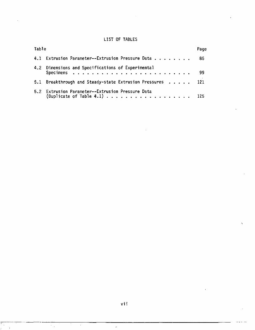
LIST OF TABLES
Table Page
4.1 Extrusion Parameter—Extrusion Pressure Data .................... 85
4.2 Dimensions and Spec i f ica t ions of ExperimentalS p e c i m e n s ..................................................................................................... 99
5.1 Breakthrough and S teady-s ta te Extrusion Pressures ....... 121
5.2 Extrusion Parameter—Extrusion Pressure Data(Duplicate of Table 4 . 1 ) ........................................................................ 125
vi i
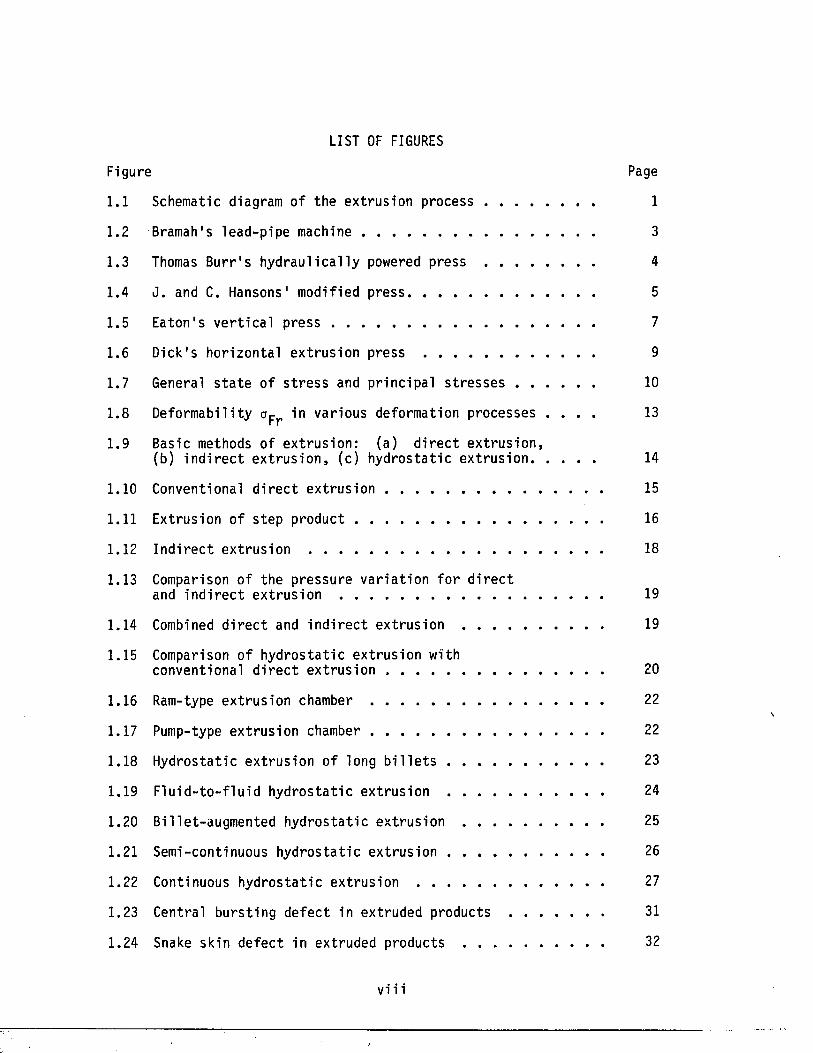
LIST OF FIGURES
Figure Page
1.1 Schematic diagram of the extrus ion process ............................ 1
1.2 Bramah's lead-pipe machine .............................................................. 3
1.3 Thomas Burr ' s hyd rau l ica l ly powered press ................................. 4
1.4 J . and C. Hansons' modified p r e s s ................................................... 5
1.5 Eaton 's v e r t i c a l press ...................................................................... 7
1.6 Dick's horizonta l ex t rus ion press ............................................ 9
1.7 General s t a t e of s t r e s s and pr incipal s t r e s s e s ......................... 10
1.8 Deformabili ty <jpr in various deformation processes . . . . 13
1.9 Basic methods of ex t rus ion : (a) d i r e c t ex t rus ion ,(b) i n d i r e c t ex t ru s io n , (c) hydros ta t ic e x t ru s io n ................. 14
1.10 Conventional d i r e c t extrusion .......................................................... 15
1.11 Extrusion of s tep p r o d u c t .................................................................. 16
1.12 In d i r ec t ex trus ion ............................................................................... 18
1.13 Comparison of the pressure v a r ia t ion fo r d i r e c tand in d i r e c t ex t rus ion ........................................................................ 19
1.14 Combined d i r e c t and in d i r e c t extrus ion .................................. 19
1.15 Comparison of hydros ta t ic extrusion withconventional d i r e c t extrus ion . ....................................................... 20
1.16 Ram-type extrus ion chamber .............................................................. 22
1.17 Pump-type extrus ion chamber .............................................................. 22
1.18 Hydrostatic ex trus ion of long b i l l e t s ......................................... 23
1.19 F lu id - to - f lu id hyd ros ta t ic extrusion ......................................... 24
1.20 Billet-augmented hydros ta t ic ex trus ion........ .................................. 25
1.21 Semi-continuous hydros ta t ic extrusion ......................................... 26
1.22 Continuous hydros ta t ic extrusion .................................................. 27
1.23 Central burs ting defec t in extruded products ......................... 31
1.24 Snake skin defect in extruded products........ .................................. 32
vi i i
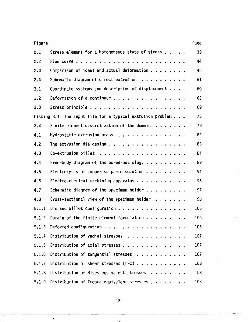
Figure Page
2.1 S tress element f o r a homogeneous s t a t e of s t r e s s ................ 39
2.2 Flow c u r v e ................................................................................................ 44
2.3 Comparison of ideal and actual deformation............................... 46
2.4 Schematic diagram of d i r e c t ex trus ion ..................................... 51
3.1 Coordinate systems and desc r ip t ion of displacement . . . . 60
3.2 Deformation of a con t inuum .............................................................. 62
3.3 Stress p r inc ip le ................................................................................... 69
Lis ting 3.1 The input f i l e fo r a typica l extrusion problem . . . 75
3.4 F in i te element d i s c r e t i z a t i o n of the domain ......................... 79
4.1 Hydrostatic extrusion press .......................................................... 82
4.2 The ext rusion die d e s i g n .................................................................. 83
4.3 Co-extrusion b i l l e t ........................................................................... 84
4.4 Free-body diagram of the bored-out slug, ................................. 89
4.5 E lec t ro lys is of copper sulphate so lu t ion . . ............................ 94
4.6 Electro-chemical machining apparatus ......................................... 96
4.7 Schematic diagram of the specimen holder ................................. 97
4.8 Cross-sect ional view of the specimen h o l d e r ........................ 98
5.1 .1 Die and b i l l e t c o n f i g u r a t i o n .......................................................... 106
5.1 .2 Domain of the f i n i t e element formulation ................................. 106
5.1 .3 Deformed conf igura tion ...................................................................... 106
5 .1 .4 D is t r ibu t ion of radia l s t r e s s e s . . ..................................... 107
5.1 .5 D is t r ibu t ion of axial s t r e s s e s ...................................................... 107
5 .1 .6 D is t r ibu t ion of tangen t ia l s t r e s s e s ..................... . . . . . 107
5.1 .7 D is t r ibu t ion of shear s t r e s s e s ( r - z ) ......................................... 108
5 .1 .8 D is t r ibu t ion of Mises equivalent s t r e s s e s .............................. 108
5 .1 .9 D is t r ibu t ion of Tresca equivalent s t r e s s e s ............................... 108
ix
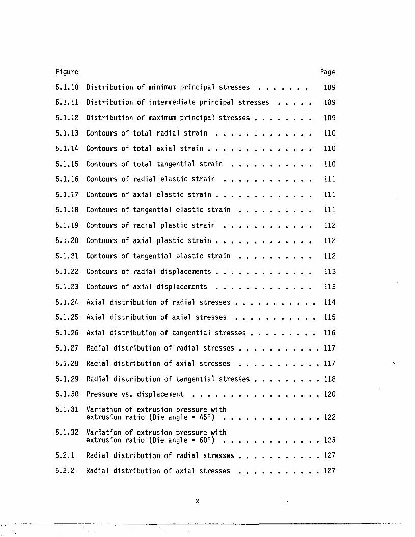
Page
109
109
109
110
110
110
111
111
111
112
112
112
113
113
114
115
116
117
117
118
120
122
123
127
127
D is t r ibu t ion of minimum pr incipal s t r e s s e s . .
D is t r ibu t ion of intermediate pr incipal s t r e s s e s
D is t r ibu t ion of maximum pr incipal s t r e s s e s . .
Contours of to t a l rad ia l s t r a i n .........................
Contours of t o t a l axial s t r a i n . . . .................
Contours of t o t a l tangen t ia l s t r a i n .................
Contours of rad ia l e l a s t i c s t r a i n .....................
Contours of axial e l a s t i c s t r a i n .........................
Contours of tangent ia l e l a s t i c s t r a i n . . . .
Contours of rad ia l p l a s t i c s t r a i n .....................
Contours of axial p l a s t i c s t r a i n .........................
Contours of tangen t ia l p l a s t i c s t r a i n . . . .
Contours of rad ia l displacements .........................
Contours of axial displacements .........................
Axial d i s t r i b u t io n of rad ia l s t r e s se s .................
Axial d i s t r i b u t io n of axia l s t r e s s e s .................
Axial d i s t r i b u t io n o f tangen t ia l s t r e s s e s . . .
Radial d i s t r i b u t io n of rad ia l s t r e s s e s . . . .
Radial d i s t r i b u t i o n of axial s t r e s s e s . . . .
Radial d i s t r i b u t io n of tangen t ia l s t r e s s e s . .
Pressure vs. displacement ......................................
Variat ion of ex trus ion pressure with extrusion r a t i o (Die angle = 45°) .....................
Variation of ex trus ion pressure with extrusion r a t i o (Die angle = 60°) .....................
Radial d i s t r i b u t io n of rad ia l s t r e s s e s . . . .
Radial d i s t r i b u t i o n of axia l s t r e s s e s . . . .
x
Figure Page
5.2 .3 Radial d i s t r i b u t io n of tangent ia l s t r e s s e s .................................. 128
5 .2 .4 Radial d i s t r i b u t io n of rad ia l s t r e s s e s .......................................... 129
5.2 .5 Radial d i s t r i b u t io n of axial s t r e sse s .......................................... 129
5.2 .6 Radial d i s t r i b u t io n of tangent ia l s t r e s s e s .................................. 130
xi
ABSTRACT
A study of hydros ta t ic co-extrusion of a ha rd -co re / so f t -c lad b i
m e ta l l i c compound has been conducted. The research employs the Sachs'
boring-out technique to determine the residual s t r e s s d i s t r i b u t io n in a
h y d ro s ta t i c a l ly co-extruded copper-clad Glidcop composite. A p a ra l le l
simulation of the res idual s t r e s s d i s t r i b u t io n in such composites
extruded to extrusion r a t i o s of 2.25, 4 .0 , and 7.5 was conducted using
the ABAQUS f i n i t e element code. The version of the code employed uses
an e l a s t i c - p l a s t i c c o n s t i tu t iv e law fo r materia l behavior and does not
simulate deformation heating e f f e c t s . Data f o r the mechanical
p rope r t ie s were obtained experimentally by constant t rue s t r a i n - r a t e
t e s t s on material iden t ica l to t h a t used in the ex trus ion experiments.
The r e s u l t s ind ica te t h a t the ext rusion pressure var ies l in e a r ly
with the natural logarithm of the extrusion r a t i o . The simulation
r e s u l t s obtained fo r t h i s p ressure , however, are genera lly higher than
those found in experiments. Comparison of the experimental and
numerical r e s u l t s of the res idual s t r e s s e s in d ica te t h a t although the
two r e s u l t s are q u a l i t a t i v e l y s im i la r , they are q u a n t i t a t iv e ly
d i f f e r e n t . In a l l cases , the experimental r e s u l t s were much lower than
those of numerical c a lc u la t io n s , implying t h a t some recovery has
occurred during the extrusion process.
The inves t iga t ion shows, however, t h a t f i n i t e element analys is in
conjunction with experimental measurements can be appl ied successfu l ly
to p red ic t and ve r i fy the q u a l i t a t i v e res idual s t r e s s pa t te rns developed
in h y d ro s ta t i c a l ly extruded products.

Dedicated to the memory of my f a th e r and to my mother.
CHAPTER 1
INTRODUCTION
1.1 General Pr incip les
1.1 .1 The Extrusion Process
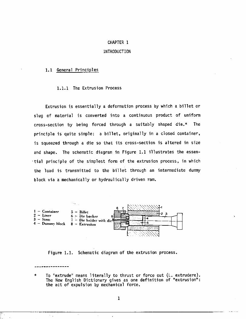
Extrusion i s e s s e n t i a l l y a deformation process by which a b i l l e t or
slug of materia l i s converted in to a continuous product of uniform
c ross -sec t ion by being forced through a su i tab ly shaped d ie .* The
p r inc ip le i s qu i te simple: a b i l l e t , o r ig in a l ly in a closed con ta iner ,
i s squeezed through a die so t h a t i t s c ross -sec t ion i s a l t e red in s ize
and shape. The schematic diagram in Figure 1.1 i l l u s t r a t e s the essen
t i a l p r in c ip le of the simplest form of the ext rusion process, in which
the load i s transmit ted to the b i l l e t through an intermedia te dummy
block via a mechanically or hydrau l ica l ly driven ram.
1 — C ontainer2 — L iner3 — Stem4 — Dummy block
Figure 1.1. Schematic diagram of the ex trus ion process.
To "extrude" means l i t e r a l l y to th r u s t or force out (L. ex t rudere) . The New English Dictionary gives as one d e f in i t io n of "extrus ion": the a c t of expulsion by mechanical force .
5 — Billet6 — Die back er £7 — Die ho lder with die8 — E xtrusion
1
2
The remarkable developments in extrus ion techniques and equipment
have aided every re la ted sec to r of indus try . The extrus ion process
provides a p rac t ica l f a b r i c a t in g method fo r producing a l im i t l e s s
v a r ie ty of p a ra l le l surfaced shapes to meet almost any design demand.
Cross-sect ions of varying geometry and complexity can be extruded.
Hollow, s o l id , th i c k , t h i n , simple, or i n t r i c a t e sec tions of any s ize
can be produced a t room temperature or a t higher temperatures , depending
on the m a te r ia l , die conf igura t ion , press s i z e , and method. In f a c t ,
there is v i r t u a l l y no shape th a t cannot be produced with the e a s i ly
extruded a l lo y s . However, d iverse sec t io n s , n a tu ra l ly associa ted with
varying degrees of d i f f i c u l t y , have been c l a s s i f i e d systemat ica l ly
according to t h e i r shapes.
An addit ional meri t o f extrus ion is t h a t i t a ffords an invaluable
means of working c e r ta in a l loys t h a t are not processed s a t i s f a c t o r i l y by
o the r forming methods, such as ro l l in g or forging. Powders and some
tender mater ia ls are good examples of such a l lo y s .
From the meta l lurg ica l point of view, perhaps the main contr ibution
has been made outs ide the extrusion process, in the development of new
a l loys fo r use in ex t rus ion ; in improved tool s t e e l s ; in providing more
homogeneous and sound b i l l e t s ; e t c .
Generally, the advances made in extrus ion have re su l ted la rge ly
from progress in engineering design and const ruction m a te r ia l s , combined
with the gradual a cq u is i t io n of technica l experience.
1.1 .2 H is to r ica l Development
The famous B r i t i sh hydraulic engineer Joseph Bramah most l ik e ly had
3
the e a r l i e s t perception of the p r inc ip le s of ex t rus ion . I t has been
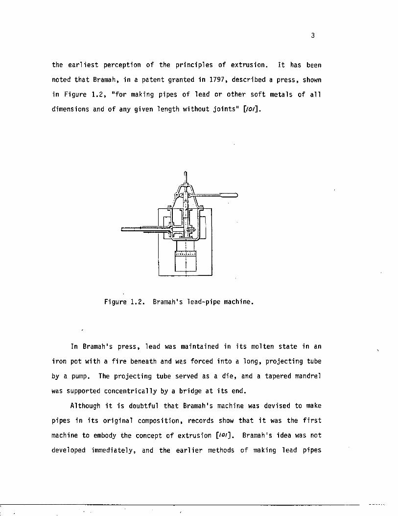
noted t h a t Bramah, in a pa tent granted in 1797, described a p ress , shown
in Figure 1 .2 , " for making pipes of lead or o ther s o f t metals of a l l
dimensions and of any given length without j o in t s " [/o/].
Figure 1.2. Bramah's lead-pipe machine.
In Bramah's p re ss , lead was maintained in i t s molten s t a t e in an
iron pot with a f i r e beneath and we,s forced in to a long, pro jec t ing tube
by a pump. The p ro jec t ing tube served as a d ie , and a tapered mandrel
was supported concen t r ica l ly by a bridge a t i t s end.
Although i t is doubtful t h a t Bramah's machine was devised to make
pipes in i t s o r ig ina l composition, records show th a t i t was the f i r s t
machine to embody the concept of extrus ion [/<>/]. Bramah's idea was not
developed immediately, and the e a r l i e r methods of making lead pipes
4
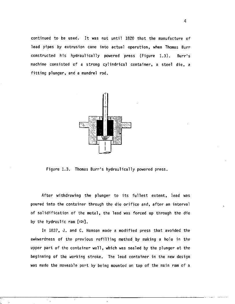
continued to be used. I t was not un t i l 1820 t h a t the manufacture of
lead pipes by extrusion came in to actual opera t ion , when Thomas Burr
constructed his hydrau l ica l ly powered press (Figure 1 .3 ) . Burr ' s
machine consis ted of a st rong cy l ind r ica l con ta ine r , a s tee l d ie , a
f i t t i n g plunger, and a mandrel rod.
t
Figure 1.3. Thomas Burr 's hydrau l ica l ly powered press .
After withdrawing the plunger to i t s f u l l e s t e x ten t , lead was
poured in to the conta iner through the die o r i f i c e and, a f t e r an in te rva l
of s o l i d i f i c a t i o n of the meta l , the lead was forced up through the die
by the hydraulic ram [/o/].
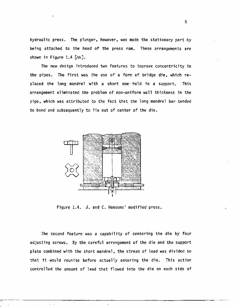
In 1837, J . and C. Hanson made a modified press t h a t avoided the
awkwardness of the previous r e f i l l i n g method by making a hole in the
upper pa r t o f the conta iner w a l l , which was sealed by the plunger a t the
beginning of the working s t roke . The lead conta iner in the new design
was made the moveable pa r t by being mounted on top of the main ram of a
5
hydraulic p ress . The plunger, however, was made the s t a t io n a r y pa r t by
being a ttached to the head of the press ram. These arrangements are
shown in Figure 1.4 [/o/].
The new design introduced two fea tu res to improve co n cen t r ic i ty in
the pipes. The f i r s t was the use of a form of bridge d ie , which r e
placed the long mandrel with a shor t one- held in a support . This
arrangement e liminated the problem of non-uniform wall th ickness in the
pipe , which was a t t r i b u t e d to the f a c t t h a t the long mandrel bar tended
to bend and subsequently to l i e out of cen te r of the d ie .
Figure 1.4. J . and C. Hansons' modified press .
The second fea tu re was a c a p a b i l i ty of cente ring the die by four
ad just ing screws. By the carefu l arrangement of the die and the support
p la te combined with the shor t mandrel, the stream of lead was divided so
t h a t i t would reun i te before a c tu a l ly en ter ing the d ie . This action
con tro l led the amount of lead t h a t flowed in to the die on each side of
6
the mandrel [/£?/].
By mid-century, the process o f lead ext rusion had become firmly
e s tab l i shed . At t h i s t ime, however, the problem of corrosion became
obvious. The next noteworthy developments arose from the i n t e r e s t then
being taken in the production of t i n - l i n e d pipes to overcome the danger
of lead poisoning t h a t occurs when lead pipes are used to convey ce r ta in
waters and o ther l i q u id s . Running molten t i n ins ide lengths o f extruded
pipe was one simple so lu t ion of ten p rac t iced .
In 1863, Shaw used a press in which p recas t hollow b i l l e t s of lead,
with an i n t e r n a l ly c a s t sleeve of t i n , were charged into the container
to produce a b i -m e ta l l i c pipe [/0 /] . A d i f f i c u l t y was encountered in
a r r iv ing a t the exact shape o f sleeve to produce a uniform l in ing of t i n
in the pipe . Four years l a t e r , in 1867, Hamon invented a remarkable
press in France th a t overcame the problem of corrosion by incorporat ing
many advanced fe a tu re s .
Hamon's machine was the f i r s t example of a heated conta iner which,
through ducts in i t s oute r j a c k e t , allowed c i r c u la t io n of steam or hot
gases to r a i se i t s temperature to 210°C. Although the hydraulic accumu
l a t o r had been invented e a r l i e r , Hamon was the f i r s t to introduce i t
in to the extrus ion press [ /o/] .
The next stage in the evolution o f the process was the in troduct ion
in 1870 of the i n d i r e c t , or inver ted , method of ex t rus ion . I t was
int roduced, s imultaneously, by two independent sources—Haines and J .
and W. Weems. The new technique made i t possib le to produce a more
uniform coating o f t i n in the pipe. This was because the r e l a t i v e
displacement of the b i l l e t and the conta iner walls was avoided; th e re
fo re , the metal remained undisturbed except in the v i c in i ty of the die .
7
With the rapid development o f the e l e c t r i c a l indus try came the need
fo r a p ro tec t ive envelope th a t would sh ie ld cables aga ins t mechanical
damage and would enable them to be submerged in water. Lead seemed to
be the ideal materia l fo r the ta sk . I t was r e l a t i v e l y immune to corro
sion and was s o f t and p l ia b le enough to be used in the laying opera
t io n s . In f a c t , by 1879 the f i r s t methods of extruding a lead sheath
d i r e c t l y onto cables were devised in France and Germany by Borel and
Wesslan, re sp ec t iv e ly . They used v e r t i c a l ex trus ion presses to extrude
hollow-cast b i l l e t s of lead over an insu la ted conductor in the form of a
tubu la r sheath. The conductor was passed in to the press through a
hollow mandrel and then was issued through the tubu la r ram [/<?/].
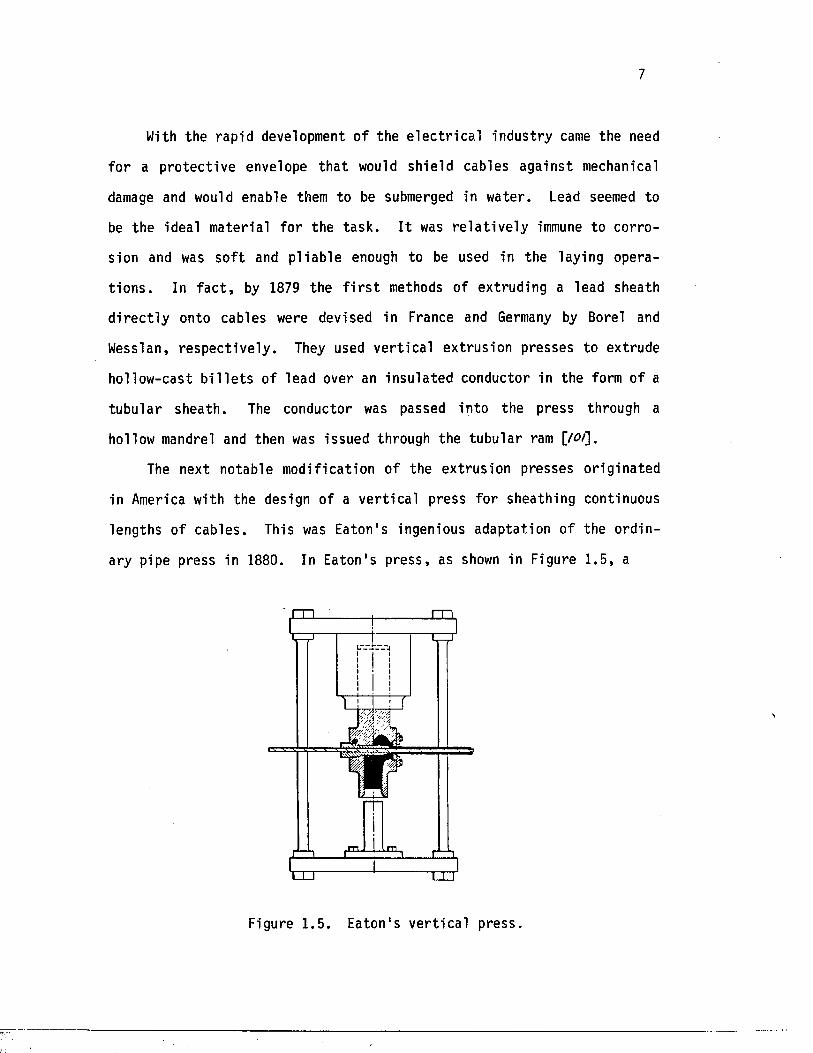
The next notable modifica tion of the extrusion presses o r ig inated
in America with the design of a v e r t i c a l press fo r sheathing continuous
lengths of cables . This was Eaton's ingenious adapta tion of the o rd in
ary pipe press in 1880. In Eaton's p ress , as shown in Figure 1.5, a
Figure 1.5. Eaton 's v e r t i c a l press .
8
charge of lead was cas t and s o l i d i f i e d in the conta iner made to flow
c i rcum fe ren t ia l ly around a mandrel over the cable t h a t was threaded
through the mandrel. The mandrel was a t a r ig h t angle to the axis of
the conta iner [/o j ]. While the development of the v e r t i c a l press ensued,
the evolut ion of the hor izontal press continued. In i t s modern form,
the horizontal press has almost e n t i r e l y surpassed o ther types.
The outstanding achievements brought about by extrusion in the
serv ice of the lead industry d i rec ted a t t e n t io n to the possible u t i l i z a
t ion of the process fo r metals with b e t t e r mechanical p ro p e r t i e s , such
as brass . Records show t h a t several e f f o r t s to extrude brass a lloys
were made during the 19th century, but the d i f f i c u l t i e s proved to be too
g re a t , and the lead presses used fo r experiments were unsuitable
The major problem with extruding b ra s s , as compared with lead, was
t h a t even the brasses most fe a s ib le for hot work had to be heated to a
temperature of a t l e a s t 600°C before they became p l a s t i c enough to
undergo the heavy deformation involved in ex trus ion . Therefore, the
problem was not only t h a t of providing a powerful p re ss , but a lso of
providing con ta ine rs , d i e s , and o ther press components t h a t could
withstand the severe thermal and s t r e s s conditions required of the
extrusion opera tion.
Few special s t e e l s had been developed in the 1800s, however, and
s o f t dies continued to be deformed along with the b i l l e t s in the ex t ru
sion of hard brasses . I t is the re fore had to overestimate the achieve
ment of Alexander Dick in overcoming the obs tac le s involved. His
decis ive invention in 1883 la id the foundation of the modern hot ex t ru
sion process, which now has been extended f a r beyond i t s o r ig inal
9
l im i t a t ions to a stage a t which i t has become one of the major metal
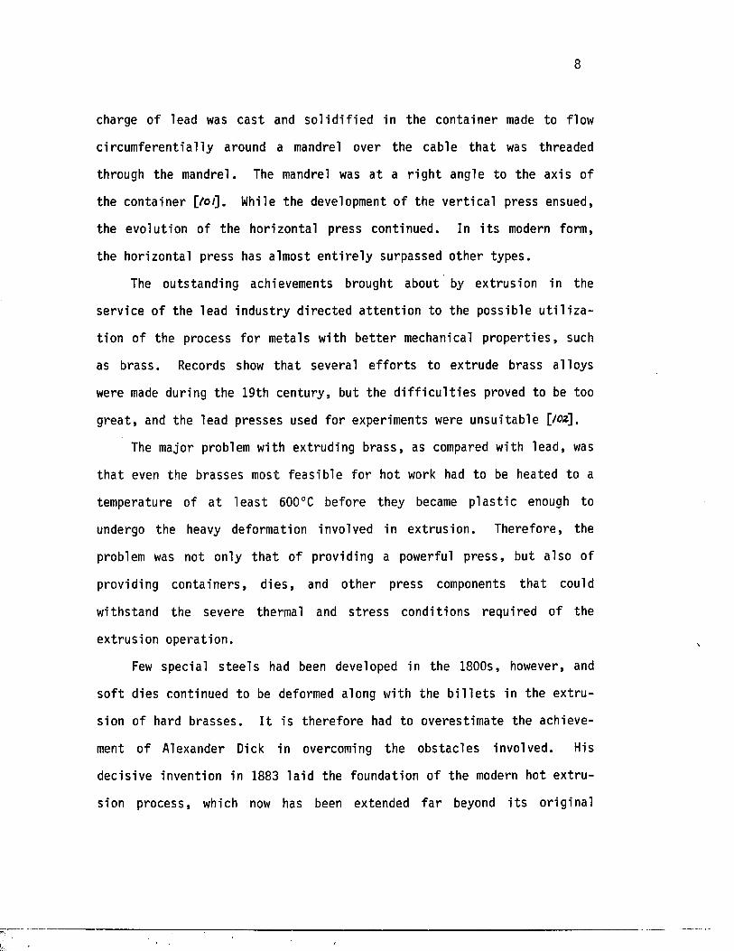
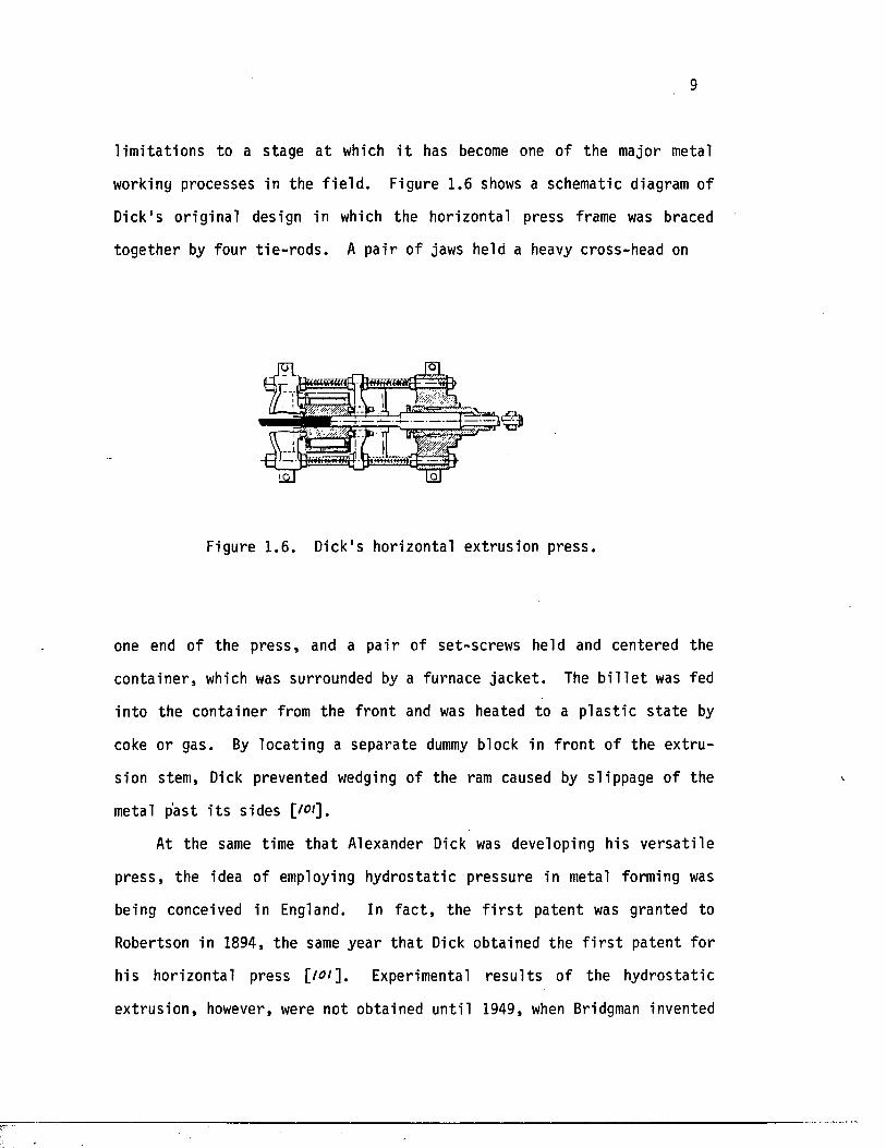
working processes in the f i e l d . Figure 1.6 shows a schematic diagram of
Dick's o r ig ina l design in which the horizonta l press frame was braced
toge ther by four t i e - r o d s . A pa i r of jaws held a heavy cross-head on
Figure 1.6. Dick's hor izontal extrusion press .
one end of the p ress , and a p a i r of set-screws held and centered the
con ta iner , which was surrounded by a furnace ja ck e t . The b i l l e t was fed
in to the conta iner from the f ron t and was heated to a p l a s t i c s t a t e by
coke or gas. By locat ing a separa te dummy block in f ro n t o f the ex t ru
sion stem, Dick prevented wedging of the ram caused by sl ippage of the
metal past i t s sides [iof].
At the same time t h a t Alexander Dick was developing his v e r s a t i l e
p re ss , the idea of employing hydros ta t ic pressure in metal forming was
being conceived in England. In f a c t , the f i r s t pa tent was granted to
Robertson in 1894, the same year t h a t Dick obtained the f i r s t pa tent fo r
his horizontal press [to1"]. Experimental r e s u l t s of the hydros ta tic
ex t rus ion , however, were not obtained un t i l 1949, when Bridgman invented
10
his high-pressure s ea l . Then he found himself in a unique pos i t ion to
study the high-pressure e f f e c t s on m a te r ia l s , and he spent the r e s t of
his l i f e doing experiments which led to a mountain o f research papers on
the subjec t [/ft*]. The f i r s t high-pressure un i t bearing Bridgman's name
was manufactured by Harwood Engineering Company of Newhall, England
[/0V]. At the same time, a s im i la r type of press was produced by the
Pressure Technology of America, headed by Bobrowsky
Systematic hydros ta t ic ex trus ion of m ater ia ls was s t a r t e d in
England by Pugh a t the National Engineering Laboratory in Glasgow. He
developed the process of hydros ta t ic ext rusion to the ex ten t o f indus
t r i a l production [/°6]. In the Soviet Union, Vereshehayin of the High
Pressure Laboratory o f The Academy of Sciences began the study of high
pressure , and the f i r s t r e s u l t s appeared in 1957 [/ofl.
The f i r s t seminar on hydros ta t ic metal working processes was held
a t B a t t e l l e Columbus Laboratories in 1967 [/M]. This f i r s t exclusive
conference ind ica tes the g rea t progress in high-pressure engineering
th a t was made in the 1960s. Today, a f t e r two decades of research and
development, the techniques of hydros ta t ic extrusion have progressed to
such a level t h a t they are now es tab l i shed as an in d u s t r ia l process.
The process has been applied success fu l ly to copper tubings , copper-clad
aluminum wire , f ine wires of noble meta ls , tubings
of aluminum a l lo y s , and so fo r th .
1.1 .3 Comparison with Other Deformation Processes
The most s ig n i f i c a n t advantage of the extrus ion process i s th a t i t
provides an invaluable means of forming c e r ta in a l loys t h a t can be
11
deformed only s l i g h t l y by o ther techniques . This is because of the
favorable compressive s t a t e of s t r e s s reached in the material during the
extrusion process ; t h i s ind ica tes a high capacity fo r deformation f a r
beyond the a b i l i t y of o ther methods. In f a c t , in the c l a s s i f i c a t i o n of
deformation processes , ex trus ion i s l i s t e d under the heading of "com
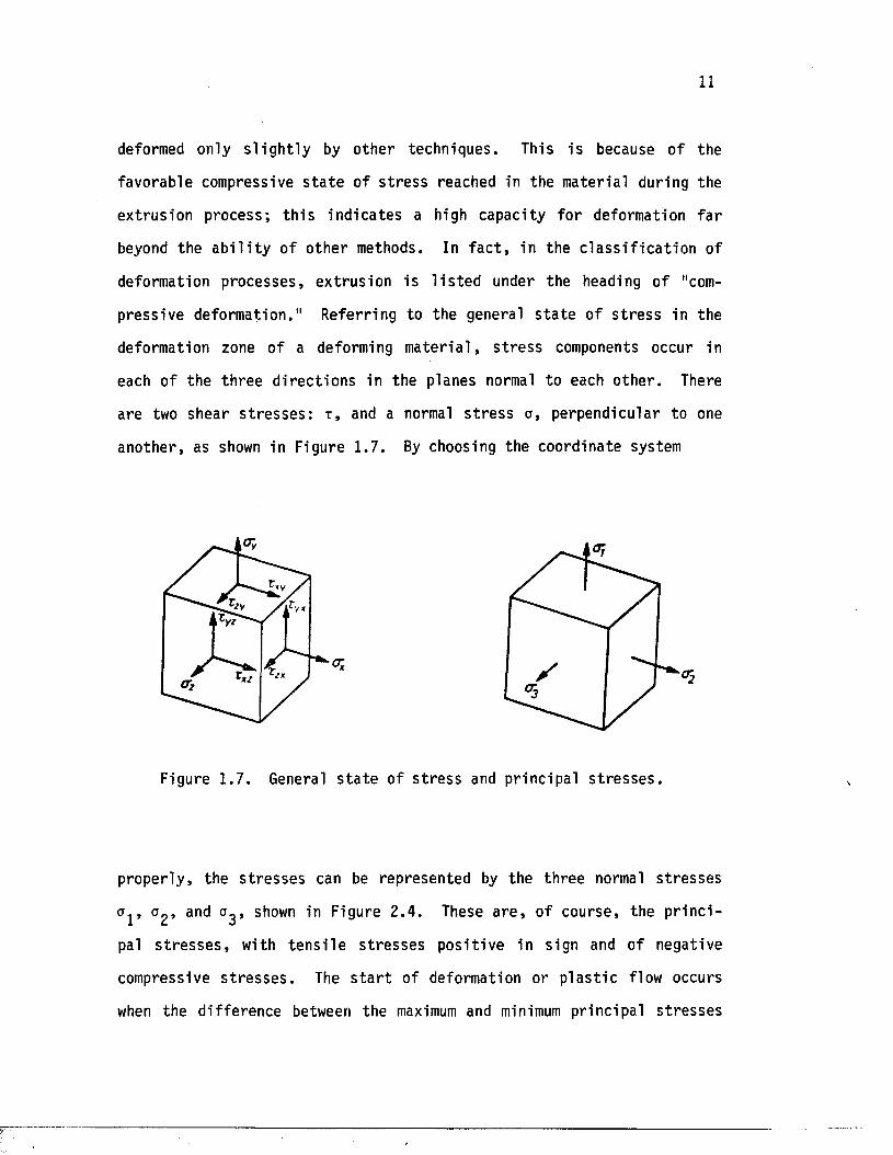
press ive deformation." Referring to the general s t a t e of s t r e s s in the
deformation zone of a deforming m a te r ia l , s t r e s s components occur in
each of the th ree d i rec t io n s in the planes normal to each o the r . There
are two shear s t r e s s e s : t , and a normal s t r e s s o, perpendicular to one
another , as shown in Figure 1.7. By choosing the coordinate system
Figure 1.7. General s t a t e of s t r e s s and pr incipal s t r e s s e s .
properly , the s t r e s s e s can be represented by the three normal s t r e sse s
Uj, a 2 , and shown in Figure 2 .4 . These a r e , o f course, the p r i n c i
pal s t r e s s e s , with t e n s i l e s t r e s s e s p os i t ive in sign and of negative
compressive s t r e s s e s . The s t a r t o f deformation or p l a s t i c flow occurs
when the d i f ference between the maximum and minimum principal s t r e sse s
12
exceeds a c e r t a in value ca l l ed flow s t r e s s k . I f a i s the maximumP 1
pr inc ipa l s t r e s s and a^ the minimum, then, according to Tresca 's y ie ld
c r i t e r i o n , the p l a s t i c flow i n i t i a t e s when
Therefore , as long as the s t r e s s grad ien t i s maintained a t the value of
flow s t r e s s , the deformation process will continue to occur whether the
s t r e s s e s are compressive or t e n s i l e . However, an important fea tu re of
ex trus ion i s t h a t a l l th ree p r inc ipa l s t r e s s e s are compressive, in
co n t ra s t to most o ther deformation processes . The tangen t ia l and rad ia l
s t r e s s e s have approximately the same magnitude but are le ss than
which i s the maximum pr inc ipa l s t r e s s .
The advantage of p l a s t i c deformation under a s t a t e of mult iaxia l
compression i s the very high s t r a i n t h a t can be a t ta ined in ex trus ion .
Even though the y ie ld s t r e s s according to Tresca i s independent of the
s t a t e o f s t r e s s , the workabi l i ty increases with increasing mean or
hydros ta t ic pressure :
am = 1/3 (a j + a 2 + a ).
This very important f a c t makes the process of hydros ta t ic extrusion even
more advantageous over o ther ex trus ion techniques .
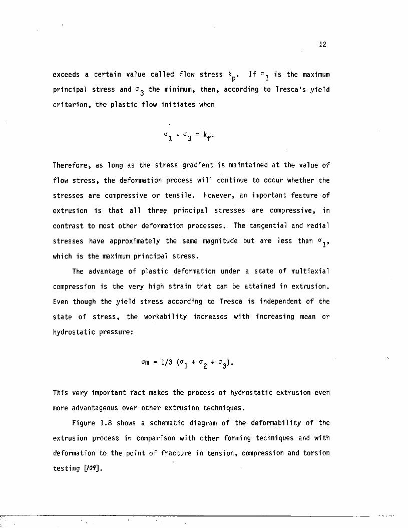
Figure 1.8 shows a schematic diagram of the deformabil i ty of the
extrusion process in comparison with o ther forming techniques and with
deformation to the point of f r a c tu re in tens ion , compression and to rs ion
t e s t in g [/Of],
13
Uniaxial co m p ress io n te st Uniaxial tensile test
! ^Torsion test
"3
Figure 1 .8 . Deformability Gpr in various deformation processes.
The extrusion process , l ike every other forming method, is not
without i t s shortcomings. The e f f e c t of f r i c t i o n can lead to the
development of a t e n s i l e s t r e s s exceeding the t e n s i l e s t rength a t the
surface of the materia l which, in tu rn , can cause surface de fec ts .
Thus, the e x t r u d a b i l i ty o f many metals is l im i ted . For tunately , because
there is l i t t l e or no f r i c t i o n between the b i l l e t and the die in hydro
s t a t i c ex t rus ion , the r e s u l t i s a more uniform deformation of the
extruded product.
14
1.2 Types of Extrusion
The proper t ie s and, in p a r t i c u l a r , the q u a l i ty o f extruded products
are influenced by the manner in which the metal has been extruded to
take up i t s f ina l dimensions and form. In f a c t , the complex r e l a t i o n
ship between the ex trus ion parameters and the flow c h a r a c t e r i s t i c s of
various a l loys makes i t impossible to use the same method fo r a l l
m a te r ia l s . D ifferen t methods are assoc ia ted with d i f f e r e n t m a te r ia ls .
According to the typica l flow behavior of a given a l lo y , a special
method of operat ion is implemented to ensure the optimum q u a l i ty of the
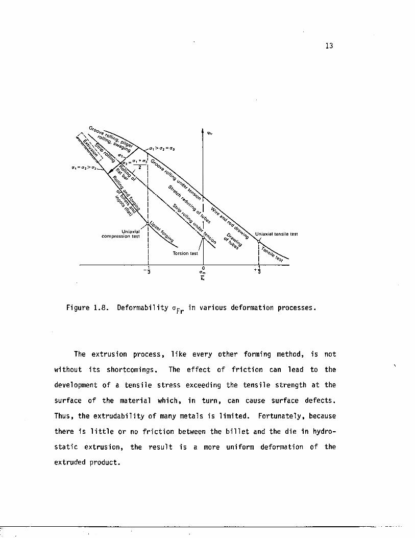
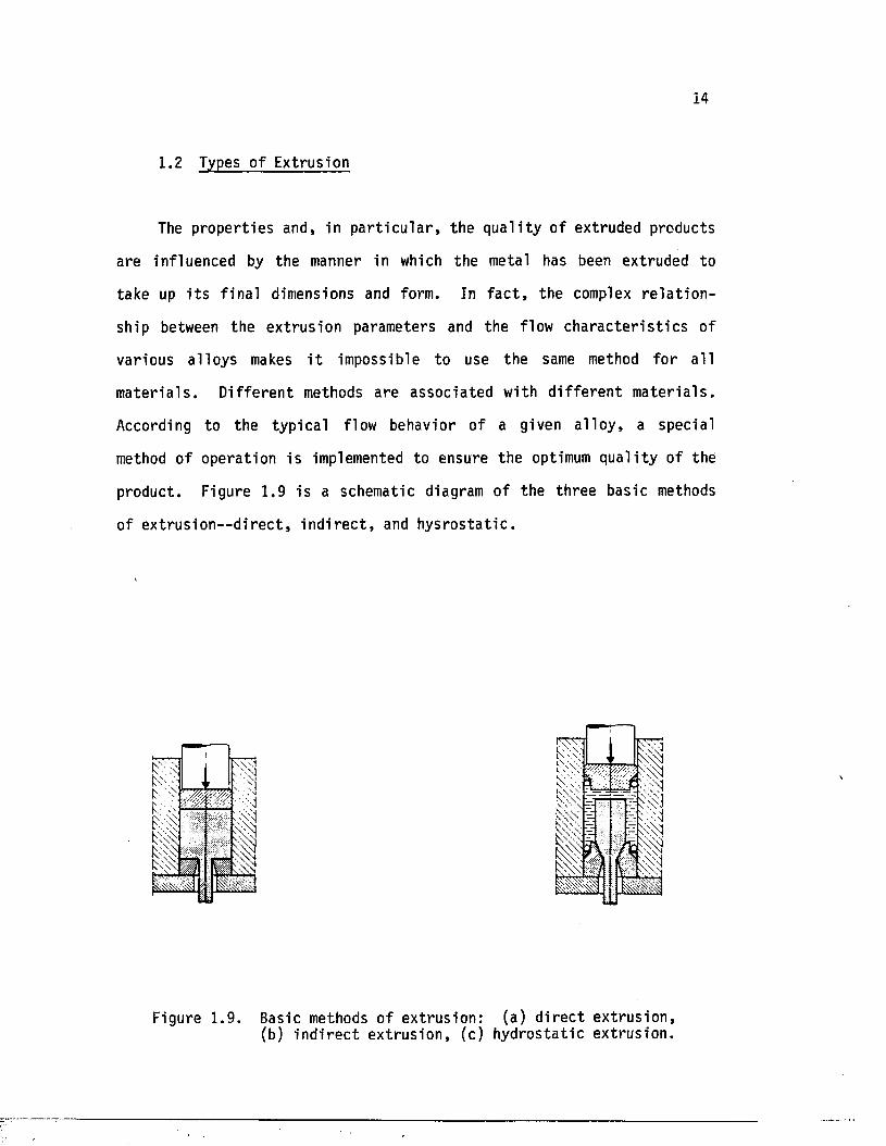
product. Figure 1.9 is a schematic diagram of the three basic methods
of ex t rus ion—d i r e c t , i n d i r e c t , and h y s ro s t a t i c .
Figure 1 .9 . Basic methods o f extrusion: (a ) d ire c t extrusion,(b ) in d ire c t extrusion , (c ) hydrostatic extrusion.
15
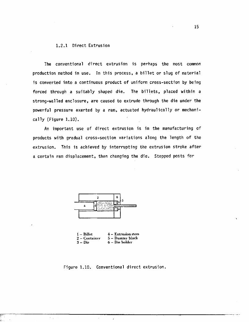
1.2.1 Direct Extrusion
The conventional d i r e c t ex trus ion i s perhaps the most common
production method in use. In t h i s process , a b i l l e t or slug of material
i s converted in to a continuous product of uniform c ross -sec t ion by being
forced through a su i t a b ly shaped d ie . The b i l l e t s , placed within a
strong-walled enclosure , a re caused to extrude through the die under the
powerful pressure exerted by a ram, actuated hydrau l ica l ly or mechani
c a l l y (Figure 1.10).
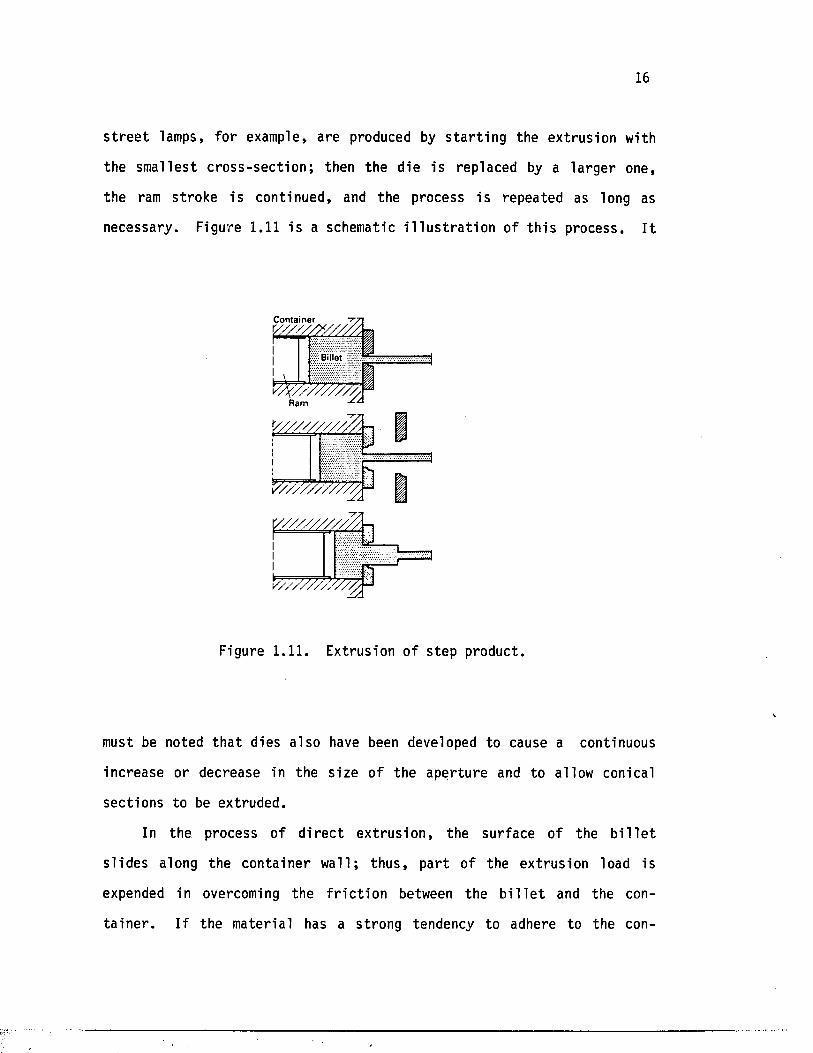
An important use of d i r e c t extrusion i s in the manufacturing of
products with gradual c ro s s -sec t ion va r ia t ions along the length of the
ex trus ion . This is achieved by in te r ru p t in g the extrusion st roke a f t e r
a c e r ta in ram displacement, then changing the d ie . Stepped posts for
2 6-3
4 5
1 - Billet 4 - E xtrusion stem2 — C on tainer 5 — Dummy block3 — Die 6 - Die hoider
Figure 1.10. Conventional d i r e c t ex t rus ion .
16
s t r e e t lamps, fo r example, are produced by s t a r t i n g the extrusion with
the smal les t c ro s s - s e c t io n ; then the die i s replaced by a l a rge r one,
the ram st roke is continued, and the process i s repeated as long as
necessary. Figure 1.11 i s a schematic i l l u s t r a t i o n of t h i s process. I t
C ontainer
Ram
v / / / / / / / / /Z \
V /// / / / / / / / / /
V //////S V / /
Figure 1.11. Extrusion o f s tep product.
must be noted t h a t dies a lso have been developed to cause a continuous
increase or decrease in the s ize of the aper tu re and to allow conical
sec tions to be extruded.
In the process of d i r e c t ex t ru s ion , the surface of the b i l l e t
s l id e s along the conta iner wal l ; thus , pa r t of the extrusion load is
expended in overcoming the f r i c t i o n between the b i l l e t and the con
t a i n e r . I f the mater ia l has a st rong tendency to adhere to the con
17
t a in e r wal l , then the per iphera l layer of the mater ia l adjacent to the
wall moves slower than the inner m a te r i a l , r e su l t in g in a nonuniform
flow p a t te rn . This nonuniformity o f the flow can cause product defects
such as cen tra l burs t ing and voids.
The d i r e c t ex trus ion process can be conducted with or without a
lu b r i can t . The use o f the lub r ica ted process n a tu ra l ly r e s u l t s in a
lower extrusion load and makes possib le the extrusion of some very
d i f f i c u l t a l lo y s . In comparison with the production methods using no
lu b r i c a n t , the presence of a good lub r i can t between the b i l l e t and the
conta iner r e s u l t s in a r e l a t i v e l y uniform s t r a i n r a t e over most of the
c ros s -sec t ion of the b i l l e t . Therefore , the e n t i r e b i l l e t is more
uniformly deformed, and the b i l l e t surface a lso forms the surface of the
extruded product—with the advantage th a t the impurit ie s on the sur face ,
such as oxides, are not drawn in to the product. The lub r ican t used
var ies from a l loy to a l lo y . For extrusion of s t e e l , fo r example, the
conta iner and the die have to be w e l l - lu b r i ca te d , whereas for copper the
s e l f - l u b r i c a t i n g oxide layer i s s u f f i c i e n t .
In s p i t e o f the po ten t ia l advantages, the lub r ican ts can be harmful
i f used improperly. Several noted cases of surface defects have been
caused by an excess or shortage o f lu b r i can t ; these cases are not
encountered in the usual method of unlubrica ted extrusion [//o]. Numer
ous papers have been published in the area of lub r i ca t ion in
ex t rus ion ; some of these a re l i s t e d in ReferencesM*HIZ-.
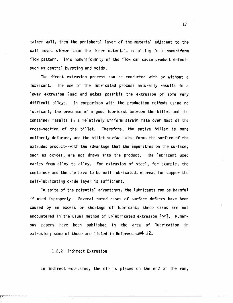
1.2.2 In d i r ec t Extrusion
In in d i r e c t ex t ru s ion , the die is placed on the end of the ram,
18
which is bored out to allow the passage of the extruded product. The
hollow stem moves r e l a t i v e l y to the con ta ine r , but there i s no r e l a t i v e
displacement between the b i l l e t and the conta iner (Figure 1.12). The
1
1 — Billet 4 — E xtrusion stem2 — C ontainer 5 - Dummy block3 - D ie 6 — Die hoider
Figure 1.12. Ind i rec t ex t rus ion .
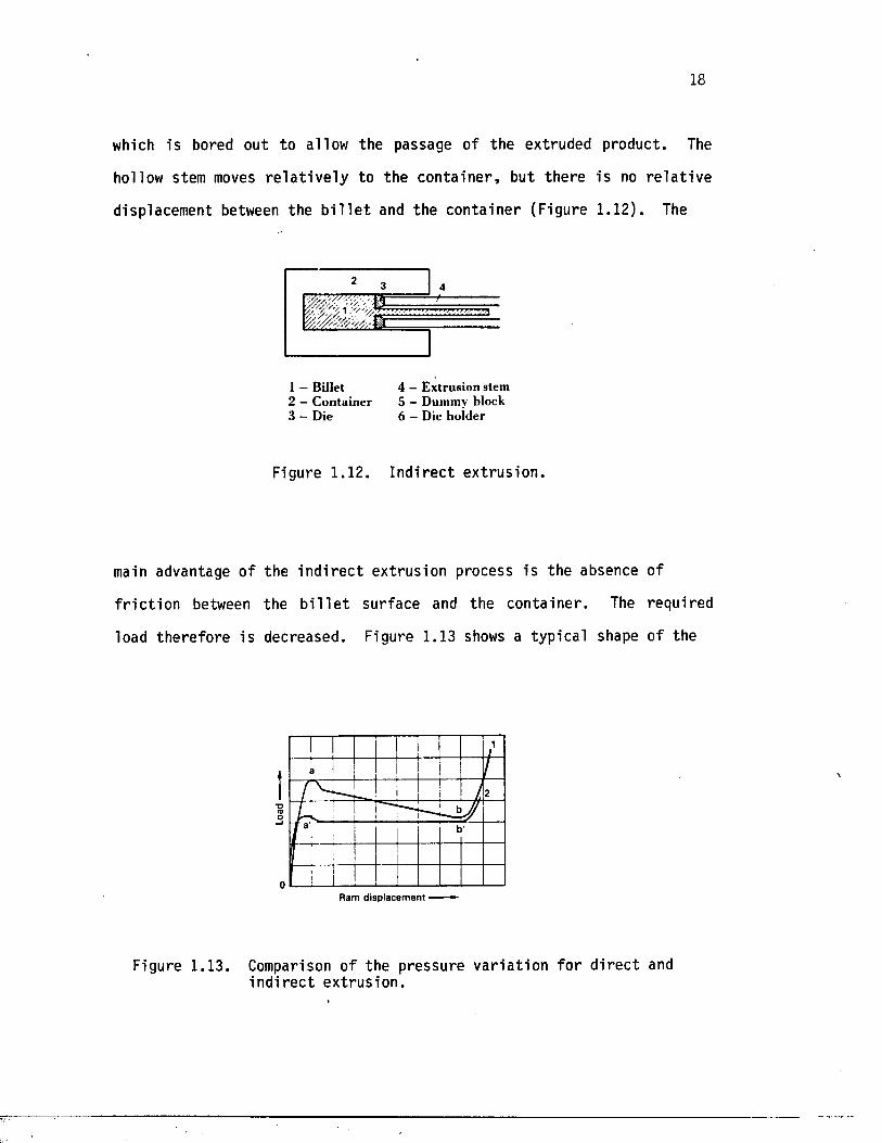
main advantage of the in d i r e c t extrusion process i s the absence of
f r i c t i o n between the b i l l e t surface and the con ta iner . The required
load the re fore i s decreased. Figure 1.13 shows a typica l shape of the
(OO—I
0Ram d isp lacem ent
Figure 1.13. Comparison of the pressure v a r i a t io n fo r d i r e c t and in d i r e c t ex t rus ion .
19
extrusion load ram displacement diagram fo r d i r e c t and in d i r e c t ex t ru
s ion. The d i f fe rence in the two peak values of pressure in d i r e c t and
in d i r e c t processes is a t t r i b u t e d to the s ig n i f i c a n t f r i c t i o n between the
surface of the b i l l e t and the con ta iner wall [ / a j ] . In f a c t , in the case
of an aluminum rod, an average savings of 30 percent in the load r e
quirements, compared to t h a t of d i r e c t ex t ru s ion , has been reported
[//*<]. Another d is t ingu ish ing fea tu re of the i n d i r e c t extrus ion process
is a l so contr ibu ted to the absence of f r i c t i o n a t the conta iner wal l—
th i s f ea tu re i s t h a t the only l im i t a t i o n of the b i l l e t length is the
length of the stem and, th e re fo re , much longer containers can be used.
This, in tu rn , means th a t longer products can be extruded by the in
d i r e c t method.
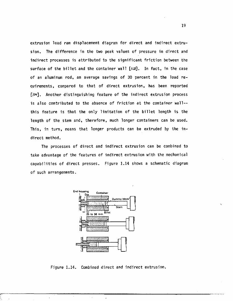
The processes of d i r e c t and in d i r e c t extrusion can be combined to
take advantage of the fea tu res of i n d i r e c t extrus ion with the mechanical
c a p a b i l i t i e s of d i r e c t presses . Figure 1.14 shows a schematic diagram
of such arrangements.
End housing P A n t l i n a r
D um m y block'
Billet
' *•••/, 'v
Figure 1 .14. Combined d ire c t and in d ire c t extrusion.
20
The process begins with i n d i r e c t ext rusion and the re fo re avoids the
i n i t i a l peak load assoc ia ted with the d i r e c t process. During th i s
s tage , the conta iner i s f r ee to move a x ia l ly 20 to 50 mm before i t
reaches a stop on the die holder. At t h i s po in t , the normal d i r e c t
extrusion takes over, and the remainder o f the process i s completed.
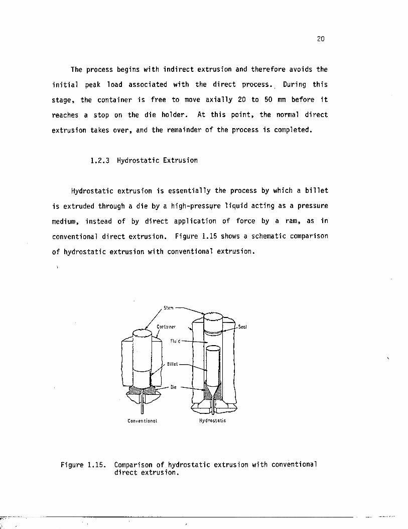
Hydrostatic ext rusion i s e s s e n t i a l l y the process by which a b i l l e t
is extruded through a die by a high-pressure l iqu id acting as a pressure
medium, ins tead of by d i r e c t app l ica t ion of force by a ram, as in
conventional d i r e c t ex t rus ion . Figure 1.15 shows a schematic comparison
of hydros ta t ic extrusion with conventional ex trus ion .
1.2 .3 Hydrostatic Extrusion
^ B ille t
C o n v e n t io n a l H y d ro s ta t ic
Figure 1.15. Comparison of hydros ta t ic extrusion with conventional d i r e c t ex t rus ion .
21
Also known as ramless, f l u i d , or hydraulic ex t rus ion , hydros ta t ic
extrus ion is one of the most prominent metal-working processes upon
which considerable research has been done in recen t year s . Although the
idea was patented by J . Robertson in 1893, i t was not un i t ! about t h i r t y
years ago t h a t the process was proposed as a new lubr ica ted extrusion
process. From th a t time on, the process has been applied to meta ls ,
special a l lo y s , and composite m a te r ia l s , with the r e s u l t s of d iverse
research and development j u s t i f y i n g i t s vas t u t i l i z a t i o n in indus t ry .
Today many hydros ta t ic ex trus ion presses up to 40 MN are in use world
wide as research and production presses [w ]»
One of the s i g n i f i c a n t fea tu res of the hydros ta t ic extrusion
process i s t h a t there i s no f r i c t i o n between the b i l l e t and the con
t a in e r wall ; thus , the length of the b i l l e t i s not l imited as i t is in
conventional ex t rus ion . Superior l u b r i c a t io n , a favorable s t r e s s
condition fo r metal deformation, and b e t t e r q u a l i ty products are a lso
advantages of hydros ta t ic ex trus ion over conventional ex t rus ion .
1 .2 .3 .1 Method of operation
In the process o f hydros ta t ic ex t ru s ion , the b i l l e t i s forced
' through the die from a high-pressure chamber in to an atmospheric-
pressure or a low-pressure chamber. In conventional ex t ru s ion , the
material maintains con tac t with th ree components: the d ie , chamber, and
the ram or dummy block. In hydros ta t ic ex t ru s ion , on the o ther hand,
the mater ia l i s surrounded by the l iqu id and is in contact with the die
only. In f a c t , when hydrodynamic lu b r ica t io n p re v a i l s , even contac t
with the die i s avoided.
22
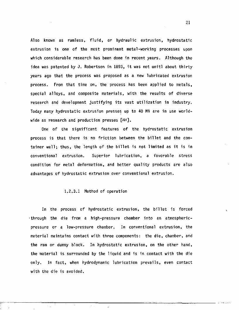
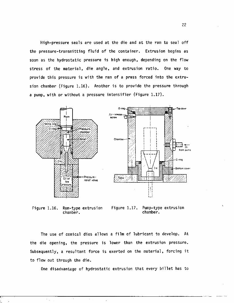
High-pressure sea ls are used a t the die and a t the ram to seal o f f
the p ressu re - t ransm i t t ing f l u i d o f the con ta iner . Extrusion begins as
soon as the hydros ta t ic pressure is high enough, depending on the flow
s t r e s s of the m a te r ia l , die angle , and extrus ion r a t i o . One way to
provide t h i s pressure i s with the ram of a press forced in to the ex t ru
sion chamber (Figure 1 .16). Another i s to provide the pressure through
a pump, with or without a pressure i n t e n s i f i e r (Figure 1.17).
/ / / / / / / / / / / , / o v M i t r e r,n9?&
Pressu re / / / /Y / / cham ber
ipressure
P re ssu re - ‘ y / , relief valve
■Top cover
screw
r~
C ham ber-
0 ring
Die •B ottom cover
Table
Figure 1.16. Ram-type extrus ion Figure 1.17. Pump-type extrusion chamber. chamber.
The use of conical d ies allows a fi lm of lub r ican t to develop. At
the die opening, the pressure i s lower than the extrus ion pressure .
Subsequently, a r e s u l t a n t force is exerted on the m a te r ia l , forcing i t
to flow out through the d ie .
One disadvantage of hydros ta t ic extrusion th a t every b i l l e t has to
23
be prepared labor ious ly to match the die angle so t h a t a seal i s formed
a t the s t a r t of the extrusion process. Another disadvantage is th a t a t
low extrusion r a t i o s , surface defects reappear in an elongated form on
the surface of the product. At low r a t i o s , th e re fo re , the e n t i r e
surface o f the b i l l e t generally has to be machined.
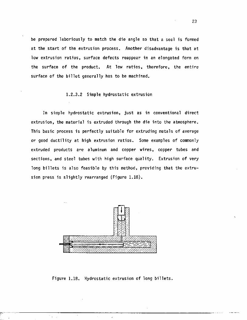
1 .2 .3 .2 Simple hydros ta t ic extrus ion
In simple hydros ta t ic ex t rus ion , j u s t as in conventional d i r e c t
ex t rus ion , the material i s extruded through the die into the atmosphere.
This basic process i s p e r fec t ly su i tab le fo r extruding metals of average
or good d u c t i l i t y a t high extrusion r a t i o s . Some examples of commonly
extruded products are aluminum and copper wires , copper tubes and
sec t io n s , and s tee l tubes with high surface q u a l i ty . Extrusion of very
long b i l l e t s is a lso fe a s ib le by th i s method, providing th a t the ex t ru
sion press i s s l i g h t l y rearranged (Figure 1.18).
Figure 1 .18 . Hydrostatic extrusion o f long b i l l e t s .
24
Mater ials can f r a c tu re during simple hydros ta t ic ext rusion because
the hydros ta t ic pressure f a l l s toward zero a t the die e x i t . One remedy
is to use the f l u i d - t o - f l u i d hydros ta t ic ex t rus ion technique.
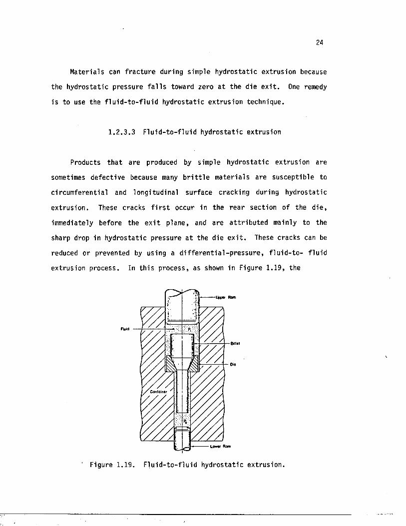
1 .2 .3 .3 F lu id - to - f lu id hydros ta t ic ext rusion
Products t h a t are produced by simple hyd ros ta t ic extrus ion are
sometimes defect ive because many b r i t t l e m ate r ia l s are suscep t ib le to
c ircumferentia l and longitudinal surface cracking during hydros ta t ic
ex t rus ion . These cracks f i r s t occur in the rea r sec tion of the d ie ,
immediately before the e x i t plane, and are a t t r i b u t e d mainly to the
sharp drop in hydros ta t ic pressure a t the die e x i t . These cracks can be
reduced or prevented by using a d i f f e r e n t i a l - p r e s s u r e , f l u i d - t o - f lu id
extrusion process . In t h i s process , as shown in Figure 1.19, the
(Jpptr Rom
Fluid
8Ht«t
Die
C o n ta in e r
Lower Rom
' Figure 1.19. F lu id - to - f lu id hydrostatic extrusion.
25
product i s extruded in to a hydraulic pressure chamber containing a
s u f f i c i e n t l y high back p ressure , ins tead of in to the atmosphere as in
simple hydros ta t ic ex t rus ion .
Although th i s method provides a reasonable so lu t ion , i t has several
disadvantages t h a t l im i t i t s app l ica t ion as a production technique. The
main setback i s higher too l ing and opera tional cost of the secondary
pressure chamber. The b i l l e t length t h a t can be used is a lso severely
l imited by the length of the back pressure conta iner .
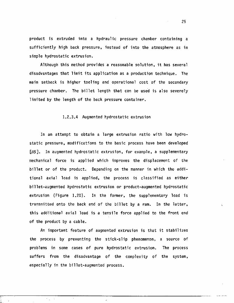
1 .2 .3 .4 Augmented hydros ta t ic ext rusion
In an attempt to obtain a large ext rusion r a t i o with low hydro
s t a t i c p ressure , modif ications to the basic process have been developed
[//5]. In augmented hydros ta t ic ex t rus ion , fo r example, a supplementary
mechanical force is applied which improves the displacement of the
b i l l e t or of the product. Depending on the manner in which the addi
t iona l axia l load is app l ied , the process i s c l a s s i f i e d as e i t h e r
bil le t-augmented hydros ta t ic extrusion or product-augmented hydros ta tic
extrus ion (Figure 1.20). In the former, the supplementary load is
transmit ted onto the back end of the b i l l e t by a ram. In the l a t t e r ,
t h i s addit iona l axial load is a t e n s i l e force applied to the f ron t end
of the product by a cable .
An important fea tu re of augmented ext rusion i s t h a t i t s t a b i l i z e s
the process by preventing the s t i c k - s l i p phenomenon, a source of
problems in some cases of pure hydros ta t ic ex t rus ion . The process
su f fe rs from the disadvantage o f the complexity of the system,
e sp ec ia l ly in the bil let -augmented process.
26
High-pressureconnectionjzm .
FF-' Ram B ille t
Figure 1.20. B i l l e t augmented hydros ta t ic ex t rus ion .
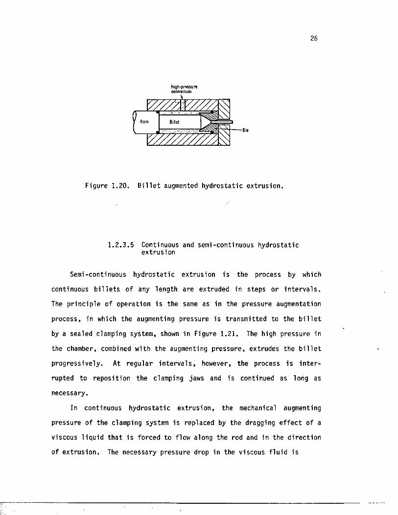
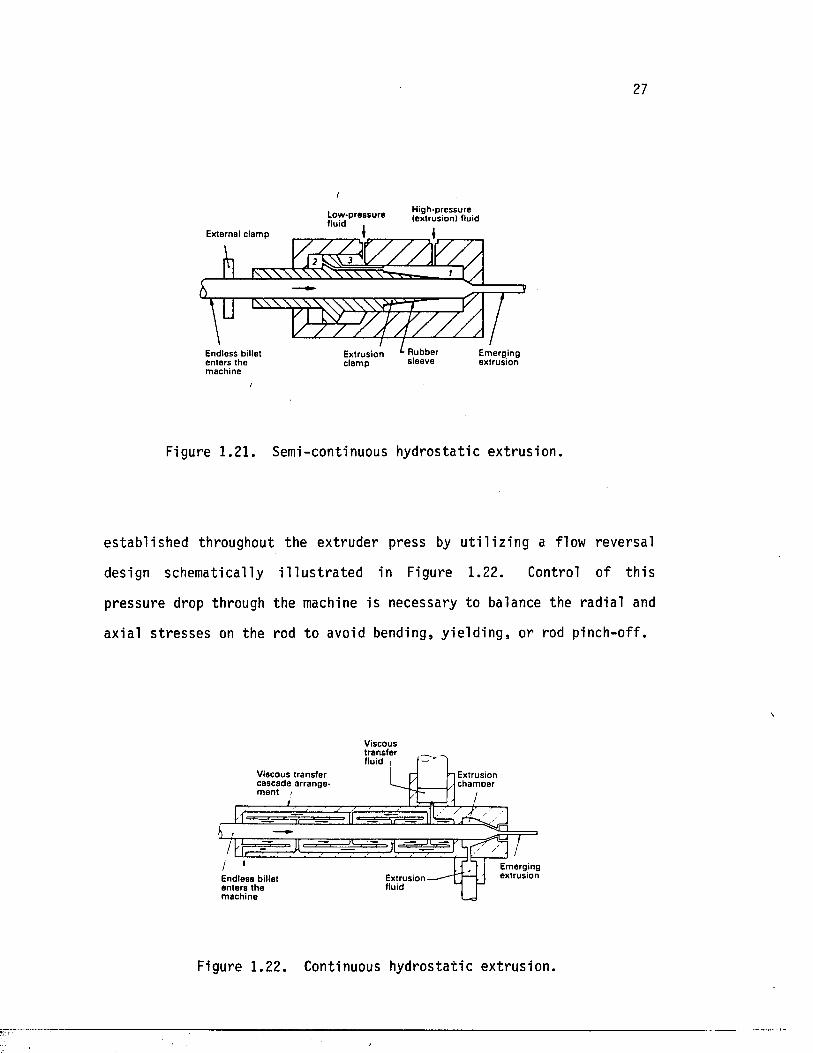
1 .2 .3 .5 Continuous and semi-continuous hydros ta t ic extrusion
Semi-continuous hydros ta t ic ext rusion i s the process by which
continuous b i l l e t s of any length are extruded in steps or i n t e rv a l s .
The p r inc ip le of opera tion i s the same as in the pressure augmentation
process, in which the augmenting pressure is transmit ted to the b i l l e t
by a sealed clamping system, shown in Figure 1.21. The high pressure in
the chamber, combined with the augmenting pressure , extrudes the b i l l e t
progress ively . At regu la r i n t e r v a l s , however, the process i s i n t e r
rupted to repos i t ion the clamping jaws and is continued as long as
necessary.
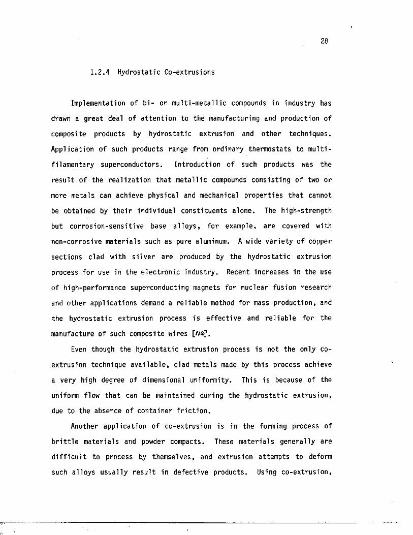
In continuous hydros ta t ic ex t rus ion , the mechanical augmenting
pressure of the clamping system is replaced by the dragging e f f e c t of a
viscous l iqu id th a t is forced to flow along the rod and in the d i rec t ion
of ex t rus ion . The necessary pressure drop in the viscous f lu id is
27
Low -pressure fluid , (extrusion) fluid
External clam p
Rubbersleeve
Em ergingextrusion
E ndless billet en te rs the
Extrusionclam p
m achinei
Figure 1.21. Semi-continuous hydros ta t ic ex trus ion .
e s tab l i shed throughout the ex truder press by u t i l i z i n g a flow reversal
design schematically i l l u s t r a t e d in Figure 1.22. Control of th i s
pressure drop through the machine i s necessary to balance the rad ia l and
axia l s t r e s s e s on the rod to avoid bending, y i e ld in g , or rod pinch-off .
Viscoustransfer fluid i
V iscous transfer casc ad e a rran g e m en t i
Extrusioncham ber
Em ergingextrusionExtrusion
fluidE ndless billet en te rs the m ach ine
Figure 1 .22 . Continuous hydrostatic extrusion.
f
28
1.2 .4 Hydrostatic Co-extrusions
Implementation of b i - or m ul t i -m eta l l ic compounds in indus try has
drawn a g rea t deal of a t t e n t io n to the manufacturing and production of
composite products by hydros ta t ic extrusion and o ther techniques .
Application of such products range from ordinary thermostats to m u l t i -
f i lamenta ry superconductors. Introduction of such products was the
r e s u l t of the r e a l i z a t i o n th a t meta l l ic compounds cons is t ing of two or
more metals can achieve physical and mechanical p roper t ie s t h a t cannot
be obtained by t h e i r individual cons t i tuen ts alone. The high-s trength
but co r ro s io n -sen s i t iv e base a l lo y s , fo r example, are covered with
non-corrosive m ate r ia ls such as pure aluminum. A wide v a r i e ty of copper
sec tions clad with s i l v e r are produced by the hydros ta t ic extrusion
process fo r use in the e l ec t ro n ic industry. Recent increases in the use
of high-performance superconducting magnets for nuclear fusion research
and other app l ica t ions demand a r e l i a b l e method fo r mass production, and
the hydros ta t ic extrusion process i s e f f e c t iv e and r e l i a b l e fo r the
manufacture of such composite wires [Wfe],
Even though the hydros ta t ic ext rusion process i s not the only co
ext rusion technique a v a i l a b le , clad metals made by t h i s process achieve
a very high degree of dimensional uniformity. This is because of the
uniform flow th a t can be maintained during the hydros ta t ic ex t rus ion ,
due to the absence of conta iner f r i c t i o n .
Another app l ica t ion of co-extrusion is in the forming process of
b r i t t l e m ate r ia ls and powder compacts. These m ate r ia ls genera l ly are
d i f f i c u l t to process by themselves, and extrusion attempts to deform
such a l loys usual ly r e s u l t in defec t ive products. Using co-extrus ion ,
29
however, a s o f t e r , more deformable metal surrounds the d i f f i c u l t - t o -
extrude m a te r ia l , and the matrix i s j o i n t l y extruded to form the desired
conf igura t ion . The product then i s machined and, upon removal of the
c lad , the f ina l product is revealed.
Clad-composite metals genera l ly are extruded in two d isp o s i t io n s of
t h e i r individual c o n s t i tu en t s : s o f t - c o re , hard-clad composites, such as
copper-clad aluminum ba rs , or hard-core , s o f t - c l a d products , such as
aluminum wires clad with s o f t lead . In genera l , due to the d i f fus ion
t h a t takes place during hydros ta t ic ex t ru s ion , clad-composite metals
produced by t h i s technique possess a st rong bonding between t h e i r
components. However, in extreme cases , such as those of la rge flow
s t r e s s r a t i o , sl ippage of the inner and oute r layers can occur a t the
in t e r f a c e , causing defec ts in the product. These defects vary depending
on whether the b i l l e t s t ru c tu r e i s s o f t - c o re , hard-clad or hard-core ,
s o f t - c l a d . In the case of the former, fo r example, clad f r a c tu re may
occur as the s o f t core i s extruded only when s l ipp ing occurs and com
pression a t the die corresponds to the f r ac tu re s t r e s s of the outer
layer . In the l a t t e r s i t u a t i o n , however, the s o f t clad i s extruded
while the hard core may a c t as a mandrel on the pipe ex trus ion .
Each conf igura t ion , th e re fo re , has i t s range of processing para
meters over which successful extrus ions can be obta ined. With proper
choice of independent parameters, such as extrusion r a t i o , die angle,
and volume f r ac t io n o f the b i l l e t c o n s t i tu e n t s , the product is
a sound, so l id rod.
30
1.3 Advantages and Disadvantages o f Dif feren t Methods of Operation
The complex re la t io n s h ip between the extrusion parameters and the
flow c h a r a c t e r i s t i c s of various a l lo y s , toge ther with the desired
q u a l i ty of the extruded products , d i c t a t e s the extrusion method adopted
fo r each case. There are d i s t i n c t advantages and disadvantages a s so c i
ated with each method. In d i r e c t ex t ru s ion , s im p l ic i ty is the main
advantage. Higher ex trus ion load i s needed, however, to overcome the
f r i c t i o n between the surface of the b i l l e t and the conta iner wal l .
Therefore, i f the materia l has a st rong tendency to adhere to the
conta iner w a l l , the r e s u l t i s a nonuniform flow p a t t e rn , which can cause
product defec ts such as cen t ra l burs ting and voids.
The main advantage of the i n d i r e c t extrus ion process is the absence
of f r i c t i o n between the b i l l e t surface and the con ta iner . The required
load the re fo re is decreased. The disadvantage of the process is tha t
the c ross -sec t iona l area of the product i s l imited by the s ize of the
hollow stem. Also, the defec ts or impurit ies on the b i l l e t surface
a f f e c t the surface of the product. Therefore, an addit ional machining
operat ion i s needed to obta in the best r e s u l t s .
The most s i g n i f i c a n t advantage charac te r iz ing the hydros ta tic
extrusion process is the complete e l imination of f r i c t i o n between the
b i l l e t and the conta iner wal l . The load a t the s t a r t o f extrus ion is
much lower, and b i l l e t s of any length can be used. Superior lu b r i ca
t i o n , a favorable s t r e s s condition fo r metal deformation, and b e t t e r
q u a l i ty products a lso are advantages of hydros ta t ic extrus ion over
conventional ex trus ion .
Hydrostatic ex trus ion has i t s disadvantages. Design and manufac-
31
t u r ing of high-pressure chambers and sea ls are d i f f i c u l t and expensive.
Also, repeated high p re s su r i za t ion of the chamber can cause fa t igue and
f a i l u r e . Another disadvantage i s the laborious prepara tion of the
b i l l e t s . The lead end of every b i l l e t must be tapered to match the die
angle in order to form a seal a t the s t a r t of the process. Also, the
e n t i r e surface of the b i l l e t s generally has to be machined to remove
surface defects which would reappear in an elongated form on the
extruded product.
1.4 Defects and Preventive Measures
Extrusion defects genera l ly are the r e s u l t o f nonuniform deforma
t ion of the m a te r ia l . There are two kinds of d e fec t s—in te rna l d e fec t s ,
such as centra l bu rs t ing , and external d e fec t s , such as surface crack
ing.
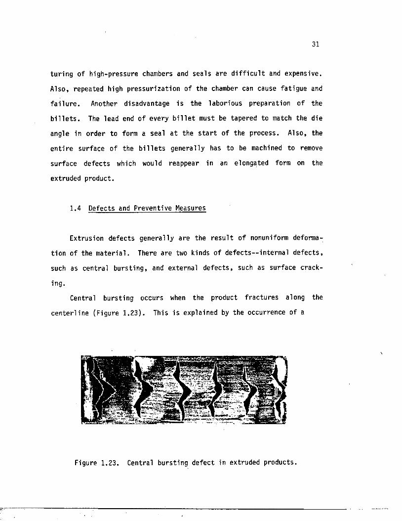
Central burs ting occurs when the product f r a c tu re s along the
cen te r l in e (Figure 1 .23). This i s explained by the occurrence of a
Figure 1.23. Central burs ting defect in extruded products.
32
s t a t e of hydros ta t ic tension ( t r i a x i a l tens ion) near the axis of the
b i l l e t . Hydrostatic tension i s the r e s u l t of formations a t high r a t io s
of b i l l e t diameter to the deformation contac t zone. Therefore, the
phenomenon is most l i k e ly to occur in extrus ions with high die angles
and low extrusion r a t i o s .
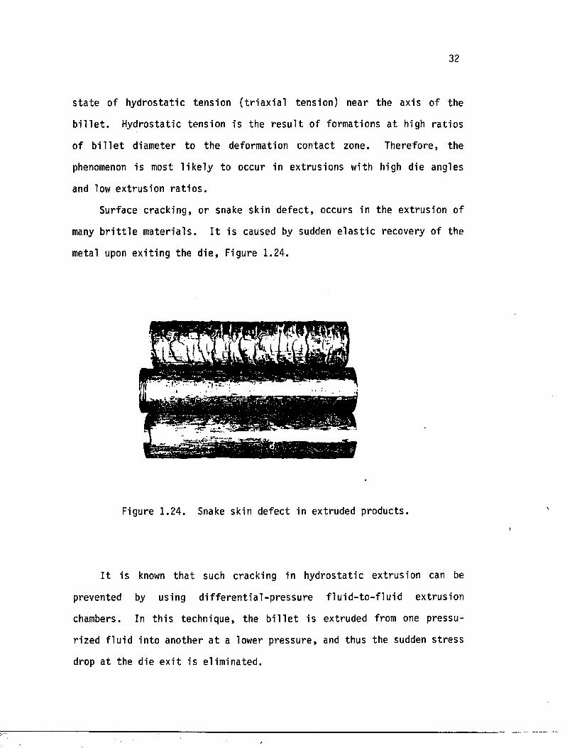
Surface cracking, or snake skin d e fec t , occurs in the extrusion of
many b r i t t l e m a te r ia l s . I t i s caused by sudden e l a s t i c recovery of the
metal upon ex i t in g the d ie , Figure 1.24.
Figure 1.24. Snake skin defec t in extruded products.
I t is known t h a t such cracking in hydros ta t ic extrus ion can be
prevented by using d i f f e r e n t i a l - p r e s s u r e f l u i d - t o - f l u i d ext rusion
chambers. In t h i s technique, the b i l l e t is extruded from one pressu
rized f lu id in to another a t a lower p ressure , and thus the sudden s t r e s s
drop a t the die e x i t i s el iminated.
33
Another approach in prevention o f the surface defect i s ext rusion
by using a double-reduction d ie . In t h i s approach, the major b i l l e t
reduction takes place a t the f i r s t land and a small reduction a t the
second land. The second reduction imposes a counterpressure in the form
of a longitudinal compressive e l a s t i c s t r e s s to the extruding product
upon e x i t from the f i r s t d ie . This prevents c ircumferentia l cracks by
reducing the axial t e n s i l e s te s ses in the oute r f ib e r s of the
product.
1.5 Scope of the Study
This inves t iga t ion is a study of hydros ta t ic co-extrusion of
b i -m eta l l ic compounds of hard-core , s o f t - c l a d m a te r ia l s . S p e c i f i c a l ly ,
the research inves t iga te s the extrus ion of copper-clad copper a l loys and
consis ts o f two phases—analy t ica l and experimental.
The ana ly t ica l phase of the inves t iga t ion i s the computer simula
t ion of the extrusion process. A nonlinear e l a s t o p l a s t i c f i n i t e element
program (ABAQUS) i s used to inves t iga te the e f f e c t s of die angle ,
extrusion r a t i o , and volume f r ac t io n of the core on the ext rusion
pressure , deformed geometry, and the res idual s t r e s s d i s t r i b u t io n in the
product. Die angles of 45° and 60° are used. Three extrusion ra t io s
(2.25, 4 .0 , and 7.5) are simulated. B i l l e t s of 100 percent copper and
100 percent copper a l l o y s , along with composites of 50 percent and 75
percent core , a lso are inves t iga ted .
The experimental phase o f the study includes the hydros ta t ic
extrusion of b i l l e t s and composites of copper and copper a l l o y s , as well
as the electrochemical material-removing experiment of residual
34
s t r e s s determination in the extruded specimens. The r e s u l t s of the two
phases then are compared to y ie ld conclusions concerning the e n t i r e
inves t iga t ion and to c a l i b r a t e the numerical s imula tion. The ca l ib ra ted
f i n i t e element program then can be used to p red ic t the proper arrange
ments of process va r iab les fo r products of b e t t e r q u a l i ty .
CHAPTER 2
LITERATURE SURVEY
Even though the idea of employing hydros ta t ic pressure fo r metal
working was f i r s t introduced in the nineteen th century , experimental
proofs of the pressure-induced d u c t i l i t y in m ate r ia l s were not ava i lab le
un t i l Bridgman's extensive study of the sub jec t . The r e s u l t s of his
in v es t iga t ion of the behavior of metals under pressure were published in
the form of a monograph [201] in 1949. He invented the high-pressure
s e a l , which put him in a uniquely advantageous pos i t ion to study the
e f f e c t s of high pressure on the metals. As a r e s u l t , he devoted the
r e s t o f his l i f e to the study of the f a sc in a t in g world of high pressure ,
and the r e s u l t s of his work l a t e r were compiled in to a seven-volume
monograph t i t l e d Collected Experimental Papers of P. W. Bridgman [ZD,*].
With the a s s i s tan ce of Abbot, former research a s s i s t a n t of Bridgman, the
Harwood Engineering Company of Newhall, Scotland manufactured the f i r s t
high-pressure u n i t ca l led the Bridgman Press. Shor tly t h e r e a f t e r , the
Pressure Technology Corporation of America, headed by Bobrowsky, pro
duced a s im i la r type of press [203].
The f i r s t repor t on hydros ta t ic ex trus ion out o f the Soviet Union
appeared in 1957 [2dY]. The work had been i n i t i a t e d the re by Vereshcha
gin o f the high-pressure labora to ry of the Academy of Sciences.
In Great B r i t a in , meanwhile, systematic work on the hydros ta t ic
extrusion of m ate r ia ls was s t a r t e d a t the National Engineering Labora
tory in Glasgow by H. H. D. Pugh [**£]. He and his a s s i s t a n t s developed
the technique of hydros ta t ic extrusion to today 's level of indus t r ia l
35
36
production.
M. Nishihara 's e a r ly recognition of the importance of the e f f e c t s
of hydros ta t ic pressure on the mechanical p roper t ie s of mater ia ls led to
a s e r ie s of research a t room temperature [ZOfc.ZO'il] and a t e levated temper
a tures [Z08,Z09] a t Doshisha Univers ity in Kyoto, Japan. He determined
the s t rength and d u c t i l i t y of carbon s t e e l , magnesium, t i tan ium, and
zinc a t pressures up to 5 ki lobars and temperatures up to 600°C \po\.
In indus t ry , there were four pioneers who used the new technology
on a commercial basis--ASEA in Sweden, Lips BV of Holland, the Western
E lec t r ic Company in the United S ta te s , and Kobe Steel in Japan [£// ] .
The main advantage of the new technique fo r commercial production was
the extremely high reduction r a t i o s obtained in one s ingle pass. The
disadvantage was the l im i ta t io n of being a batch technique. I t is not
without reason, th e re fo re , th a t the decade of the 1970s saw an increase
in the commercial use of the batch-type production un i t on one hand, and
of research and development of a continuous process on the o ther.
Numerous ideas on the continuous process were conceived, and some of
them were subjected to experimentation.
Continuous ex trus ion was introduced f i r s t by Fuchs [Z/z], His
viscous drag extrusion marked the beginning of a s e r ie s of at tempts to
use the technique in forms other than batch production. Other novel
methods were proposed as w e l l , such as "continuous extrus ion forming,"
or so-ca l led "conforming," by Green [Z/3]; " l in e a r continuous ex t rus ion ,"
or " l inex ," by Black and Voorhes [2A/]; "ex t ro l l ing" by Avitzur [2/5]; and
"hydros ta t ic extrusion with continuous feed" by Kobe Steel [2/fc].
Great progress a lso has been repor ted with regard to the theory of
hydros ta t ic ex trus ion . Analytical methods t h a t had been used in
37
conjunction with metal forming processes p r io r to the hydros ta t ic
ex trus ion technique were brought in to the ana lys is of the new process.
S p e c i f i c a l ly , the slab method, or free-body approach, was the most
f requent ly employed. Other techniques such as "extremum p r in c ip le s , "
the " s l ip l in e f i e l d theory ," and e sp e c ia l ly the "upper bound approach"
a lso have been qu i te successful [21*?]. Analytical formulas made i t
possib le to p red ic t the pressure required to extrude mater ia ls with a
prescribed amount of deformation which, in tu rn , was useful in
determining the optimum shape of the die and the s e lec t ion of o ther
process parameters.
More re c en t ly , however, numerical techniques such as f i n i t e d i f f e r
ences and f i n i t e elements have been appl ied to analyze the s t r e s s and
s t r a i n d i s t r i b u t io n s in the products. The mathematical t o o l s , however,
require the accura te , c o n s t i t u t i v e equation of the b i l l e t materia l to be
known as the basis o f the c a lc u la t io n .
2.1 THEORETICAL BACKGROUND
2.1 .1 Introduct ion
Because of the s im p l ic i ty in handling, some of the ana ly t ica l
methods have been applied to many of the forming processes . In the case
of hydros ta t ic ex t rus ion , the s lab method, the lower bound theory , and
the upper bound theory have been employed to est imate the s t r e s s e s as
well as the extrus ion pressure [2tf]. The s l i p l in e f i e l d method pre
sents an accura te so lu t ion fo r plane s t r a i n problems with r i g i d , per
f e c t l y p l a s t i c m a te r ia l s . Various s l i p l in e f i e l d s fo r ext rusion are
38
c i t e d by Johnson and Kudo [2.1?]. Other th eo re t ic a l methods such as
Ewing's s e r i e s method [220] and C o l l in s ' matrix method [22/] were proposed
l a t e r . These methods, however, are l imi ted to plane s t r a i n problems and
do not seem to be usable in p rac t ica l s i t u a t i o n s .
In recen t y e a r s , on the o ther hand, a new and more accurate numeri
cal ana lys is of the ex trus ion process has been obtained by employing the
f i n i t e element technique. The f i n i t e element method is a numerical
technique fo r solving d i f f e r e n t i a l equations governing engineering
problems by dividing the materia l in to many hypothetical elements i n t e r
connected a t nodal po in ts . For ana lys is of metal forming, there are two
schemes of the f i n i t e element method, i . e . , an e l a s t i c - p l a s t i c one and a
r i g i d - p l a s t i c one. In l a t e r s ec t io n s , the abovementioned th e o r ie s , as
well as the f i n i t e element method, are discussed in more d e t a i l .
To express the equations of mechanics in Cartesian coordinates in
simple forms, i t i s convenient to use the s t r e s s tensor :
where the f i r s t subsc r ip t o f a s t r e s s component re fe r s to the d i rec t ion
of the normal to the a rea , and the second subscr ip t r e fe r s to the d i r e c
t ion of the force component, Figure 2.1 .
2 .1 .2 Basic Concepts
( 2 . 1 )
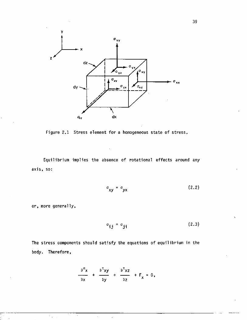
39
V
vv
v*XV
dy 'x zzx
dx
Figure 2.1 S tress element fo r a homogeneous s t a t e of s t r e s s .
Equilibrium implies the absence of ro ta t io n a l e f f e c t s around any
a x i s , so:
a = a ( 2 . 2 )xy yx v ‘
o r , more genera l ly ,
The s t r e s s components should s a t i s f y the equations of equi l ibrium in the
body. Therefore,
9°x 3Txy 3txz + ------ + + F = 0,3x 3y 3z
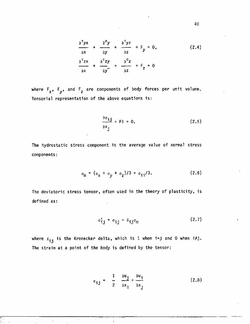
40
9Tyx a°y 9Tyz +--- ------ + + F = 0, (2.4)
9x ay az y
9 t 2X 9t z y 9° Z + — _ + -------- + F = 0
ax ay az
where F , F , and F are components of body forces per un i t volume, x y zTensorial rep resen ta t ion of the above equations i s :
a _•— ^ + Fi = 0. (2.5)
9xj
The hydros ta t ic s t r e s s component i s the average value of normal s t r e s s
components:
°m = (ax + °y + az ^ = c i i /3* (2.6)
The dev ia to r ic s t r e s s t enso r , of ten used in the theory o f p l a s t i c i t y , is
defined as:
a i j = a i j ’ 6i j am (2*7)
where 6-. i s the Kronecker d e l t a , which i s 1 when i=j and 0 when i ^ j . ̂0
The s t r a i n a t a point of the body i s defined by the tensor :
-i j
1 au, au._ — I + — L ( 2 .8 )
a x . axj
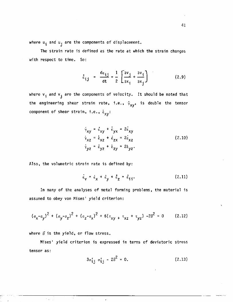
41
where u. and u. are the components o f displacement.* J
The s t r a i n r a t e is defined as the r a t e a t which the s t r a i n changes
with respec t to t ime. So:
de- • 1e - = J = -
1J dt 2 L a x . ax *)av. av.—1 + — | ( 2 . 9 )
where v. and v. are the components of v e lo c i ty . I t should be noted th a t■ Jthe engineering shear s t r a i n r a t e , i . e . , j , i s double the tensorxycomponent o f shear s t r a i n , i . e . , exy:
V = r + r = 2 PYx y x y y x fcxy
i'xz = Sxz + =zx = 2=xz <2’ 10)
*yz ■ £yz + £zy = 2lyz'
Also, the volumetric s t r a i n r a t e i s defined by:
K = £x + + l z = E*ii* (2*n )
In many of the analyses o f metal forming problems, the materia l is
assumed to obey von Mises1 y ie ld c r i t e r i o n :
( o x - o y ) 2 + (oy ~oz ) 2 + ( c z - o x ) 2 + 6(Txy + t xz + xy z ) - 2 a 2 = 0 ( 2 . 1 2 )
where a i s the y i e l d , or flow s t r e s s .
Mises1 y i e ld c r i t e r i o n i s expressed in terms of d ev ia to r ic s t r e s s
tensor as:
3 a \ . a j j - 2a2 = 0. ( 2 . 13)
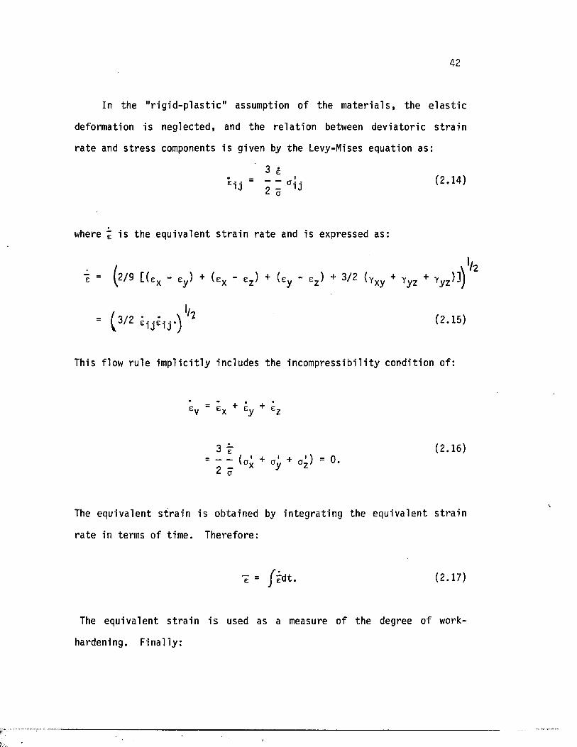
42
In the " r i g i d - p l a s t i c " assumption of the m a te r i a l s , the e l a s t i c
deformation is neglec ted , and the r e l a t i o n between d ev ia to r ic s t r a i n
r a t e and s t r e s s components i s given by the Levy-Mises equation as:
3 g
Ei j ~ : i ai3 (2,14)a
where % i s the equivalent s t r a i n r a t e and is expressed as:
1 = (2/9 [ ( ex - ey ) + ( e x - ez ) + (ey - ez ) + 3/2 (yxy + Yyz + yy z )] j
= ( 3 /2 (2 - 15)
This flow ru le im p l i c i t l y includes the incompress ib i l i ty condition of:
V*
e = e + e + eE.y C-x C.y C-z
3 t (2 .16)= (av + a,', + a^) = 0.
a
The equivalent s t r a i n i s obtained by in teg ra t in g the equivalent s t r a in
r a t e in terms of t ime. Therefore:
e = y"edt. (2 .17)
The equivalent s t r a i n i s used as a measure o f the degree of work-
hardening. F inally :
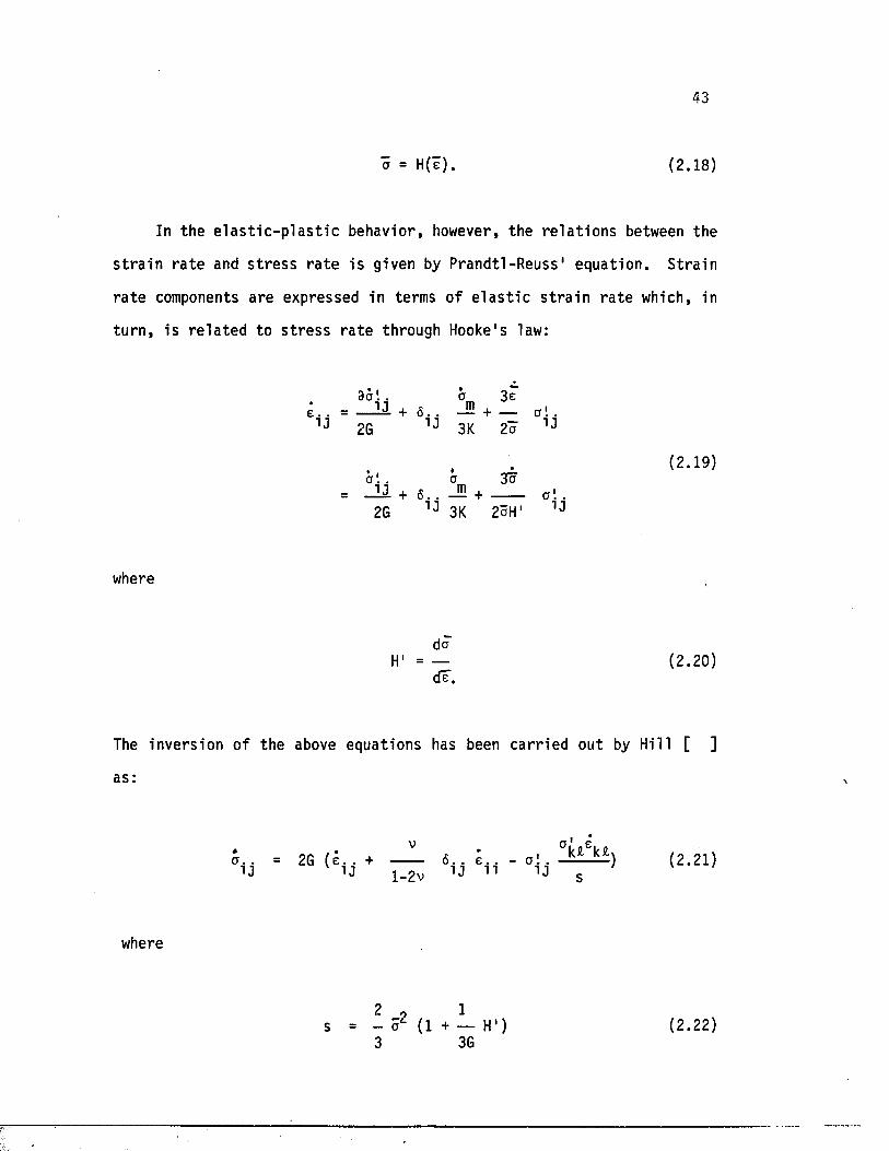
43
a = H(e). (2.18)
In the e l a s t i c - p l a s t i c behavior, however, the r e l a t io n s between the
s t r a i n r a t e and s t r e s s r a t e i s given by Prandtl -Reuss ' equat ion. S tra in
r a t e components are expressed in terms of e l a s t i c s t r a i n r a t e which, in
tu rn , i s r e l a t e d to s t r e s s r a t e through Hooke's law:
9ct! . a 3ee . . = _ M + 6 . . -E + — a ! .
1J 2G 1J 3K 2 a 1J
2G 1J 3K 2aH1 1J
where
(2.19)
daH' = — (2.20)
dT.
The invers ion of the above equations has been ca r r ied out by Hill [ ]
as:
a. . = 2G ( e . . + i j v iJ l -2v
6. . e . .IJ 11
, Pk£ekfcv i J c
( 2 . 2 1 )
where
2 , 1- o* (1 + — H') (2.22)3 3G
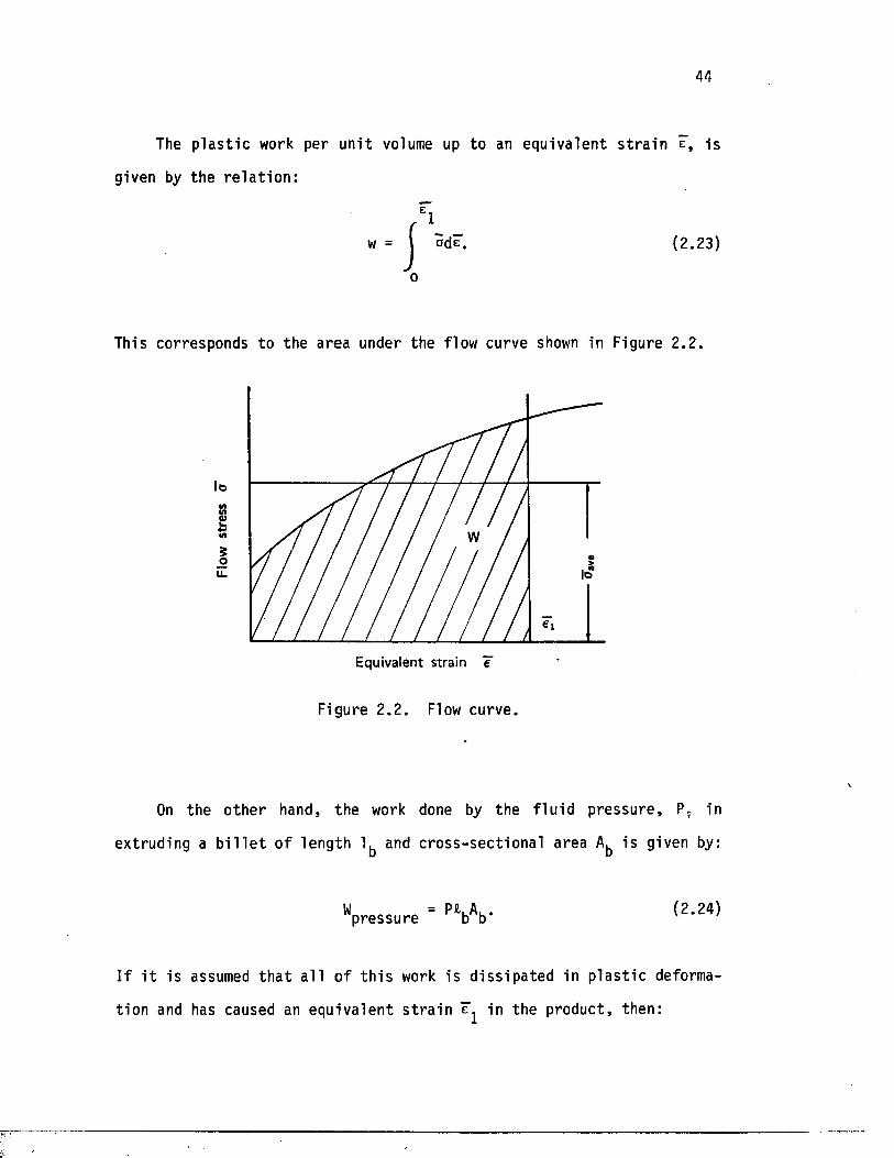
44
The p l a s t i c work per un i t volume up to an equivalent s t r a i n e, is
given by the r e l a t i o n :
'1w = \ odeT.
o■I
(2.23)
This corresponds to the area under the flow curve shown in Figure 2.2 .
loMtn
Equivalent strain e
Figure 2 .2 . Flow curve.
On the o ther hand, the work done by the f lu i d p ressure , P. in
extruding a b i l l e t o f length 1^ and c ross -sec t iona l area i s given by:
"pressure " M b V (2 ' 24)
I f i t is assumed t h a t a l l o f t h i s work is d i s s ipa ted in p l a s t i c deforma
tion and has caused an equivalent s t r a i n in the product, then:
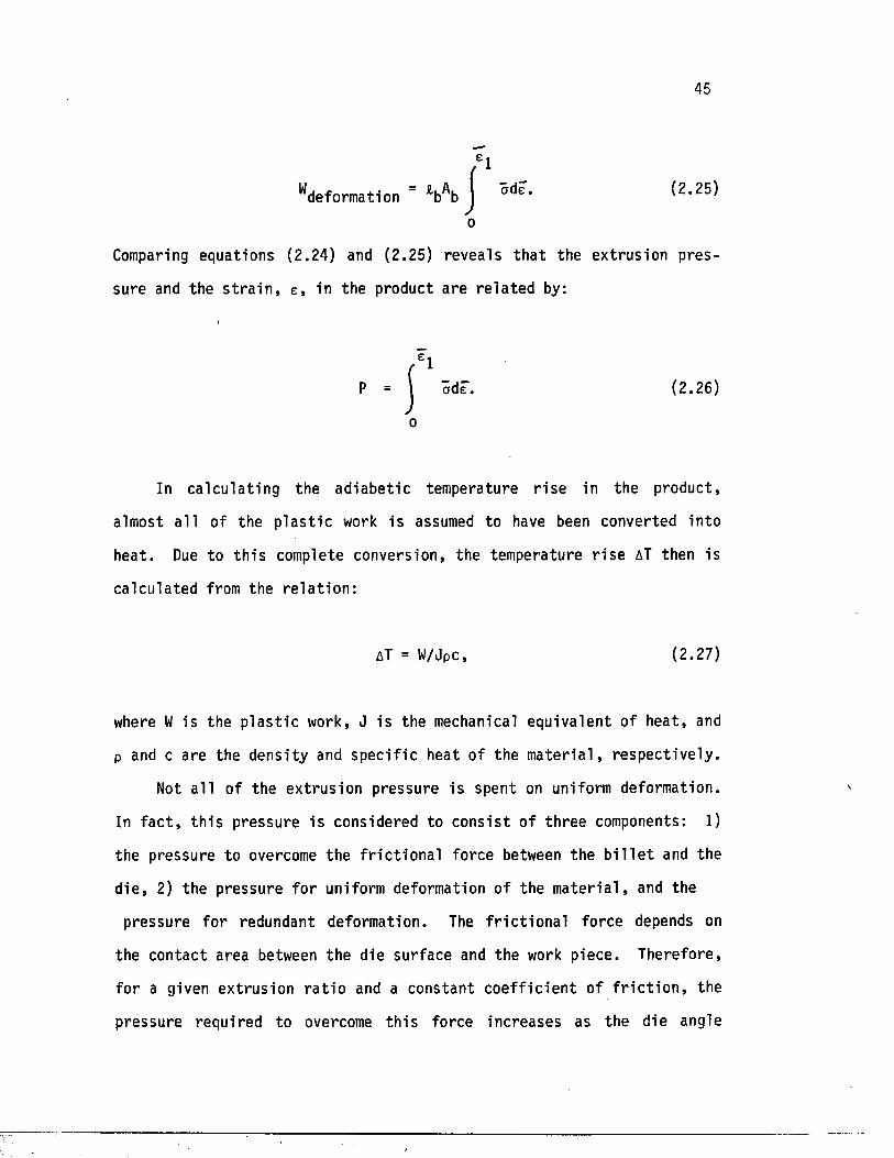
45
^deformation " £b^b (2.25)
o
Comparing equations (2.24) and (2.25) reveals t h a t the extrus ion p res
sure and the s t r a i n , e , in the product are r e l a t e d by:
In ca lcu la t ing the ad iab e t ic temperature r i s e in the product,
almost a l l of the p l a s t i c work is assumed to have been converted in to
heat. Due to t h i s complete conversion, the temperature r i s e AT then is
ca lcu la ted from the r e l a t i o n :
where W is the p l a s t i c work, J i s the mechanical equivalent o f hea t , and
p and c are the densi ty and s p ec i f ic heat of the m a te r ia l , r e spec t ive ly .
Not a l l of the ex trus ion pressure is spent on uniform deformation.
In f a c t , t h i s pressure i s considered to c o n s i s t of th ree components: 1)
the pressure to overcome the f r i c t i o n a l force between the b i l l e t and the
d ie , 2) the pressure fo r uniform deformation of the m a te r i a l , and the
pressure fo r redundant deformation. The f r i c t i o n a l force depends on
the con tac t area between the die surface and the work piece . Therefore,
fo r a given extrus ion r a t i o and a constant c o e f f i c i e n t of f r i c t i o n , the
pressure required to overcome th i s force increases as the die angle
P (2.26)
o
AT = W/Jpc (2.27)
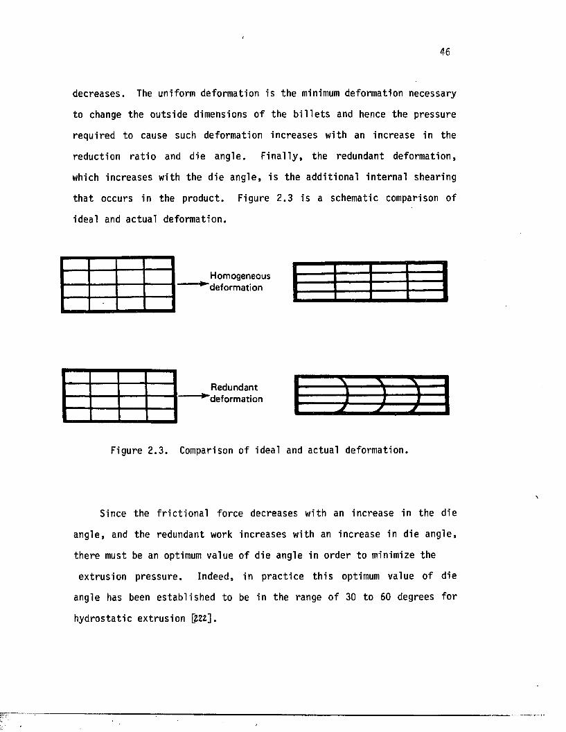
46
decreases . The uniform deformation is the minimum deformation necessary
to change the outs ide dimensions of the b i l l e t s and hence the pressure
required to cause such deformation increases with an increase in the
reduction r a t i o and die angle . F in a l ly , the redundant deformation,
which increases with the die angle , i s the add i t iona l in te rna l shearing
th a t occurs in the product . Figure 2.3 i s a schematic comparison of
ideal and actual deformation.
H o m o g en eo u s^ d e f o r m a t i o n
R e d u n d a n t"^ d e fo rm a t io n
Figure 2 .3 . Comparison of ideal and actual deformation.
Since the f r i c t i o n a l force decreases with an increase in the die
angle , and the redundant work increases with an increase in die angle,
there must be an optimum value of die angle in order to minimize the
extrus ion pressure . Indeed, in p rac t ice t h i s optimum value of die
angle has been e s tab l i shed to be in the range of 30 to 60 degrees fo r
hydros ta t ic ex trus ion [Z22].
\
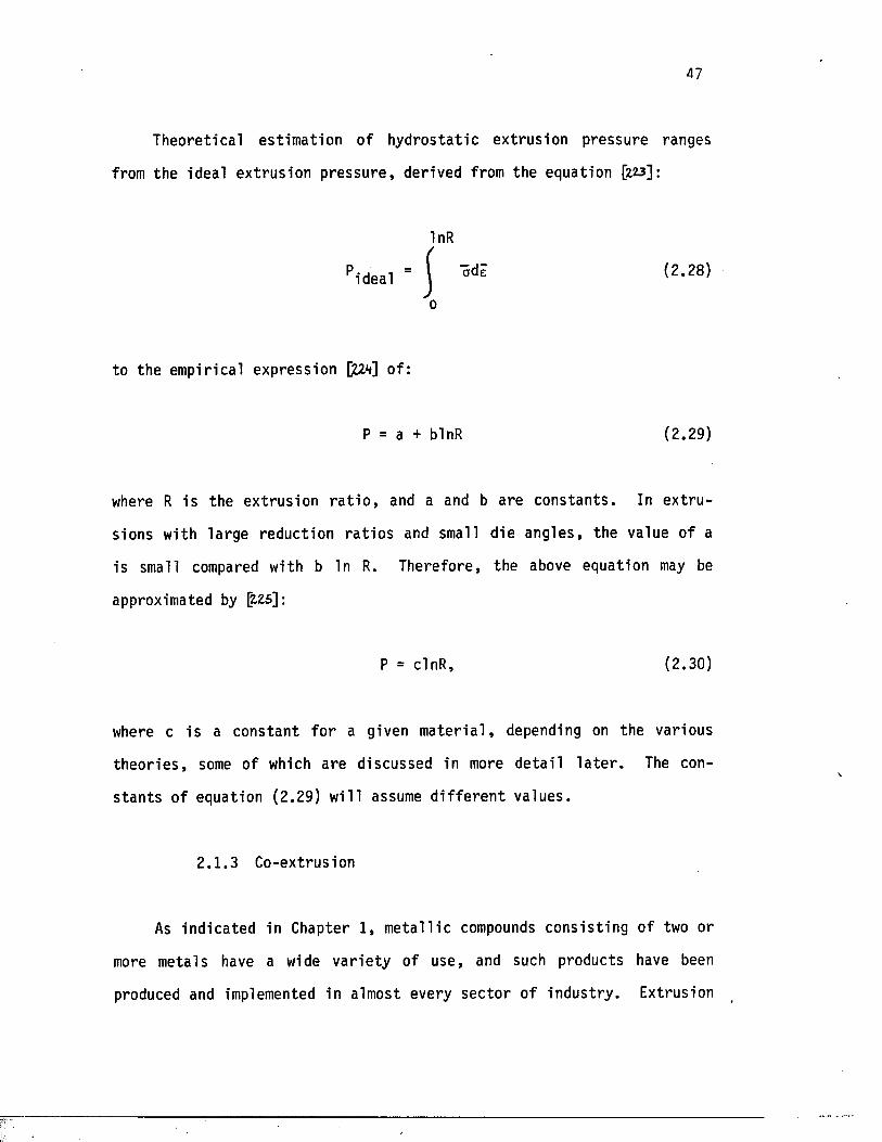
47
Theoretical es timation of hydros ta t ic ex trus ion pressure ranges
from the ideal ex trus ion p ressu re , derived from the equation [Z23]:
InR
Pideal ’ ] <2 ' 28>0
to the empirical expression C&V] of:
P = a + blnR (2.29)
where R i s the ex trus ion r a t i o , and a and b are cons tan ts . In e x t ru
sions with la rge reduction r a t i o s and small die angles , the value of a
is small compared with b In R. Therefore, the above equation may be
approximated by [z.25]:
P = clnR, (2.30)
where c i s a constant f o r a given m a te r i a l , depending on the various
th e o r i e s , some of which are discussed in more d e ta i l l a t e r . The con
s tan t s of equation (2.29) wi l l assume d i f f e r e n t va lues .
2 .1 .3 Co-extrusion
As indica ted in Chapter 1, m e ta l l ic compounds cons is t ing of two or
more metals have a wide va r ie ty of use, and such products have been
produced and implemented in almost every sec to r of indus t ry . Extrusion
48
in general and hydros ta t ic ex trus ion in p a r t i c u l a r provide e f f i c i e n t
means o f producing such products and, th e re fo re , numerous inves t iga t ions
have been ca r r ied out by researchers in the pas t [226,211,22*8,229,2?o].
The ana lys is of co-extrus ion of b im e ta l l ic compounds has been
categorized by the d i sp o s i t io n s of t h e i r individual c o n s t i tu e n t s , namely
so f t - c o r e , hard-clad composites, or hard-core , s o f t - c l a d products.
Copper-clad aluminum bars are an example of the former, while Glidcop
(hard copper a l loys ) clad with copper represen t the l a t t e r . Current
inves t iga t ion i s of the hard-core , so f t - c l a d composite.
The th e o re t ic a l inves t iga t ions of co-extrusion have ranged from
empirical techniques [131,232.] to complex upper bound analyses [233] with
computer-aided numerical simulation techniques appearing in recen t years
[23v,235,Z3fc].
In order to obtain est imates of the extrusion pressure fo r com
posi te b i l l e t s , Alexander and Hartley [23*7] made extensions to the
analys is developed fo r homogeneous m a te r ia l s . They es tab l i shed an upper
bound on extrus ion pressure by choosing p a r t i c u l a r ve loc i ty f i e l d s . The
pressure expression used was of the form in equation 2.29, and the
c o e f f i c i en t s a and b were r e l a t e d to the volume f r ac t io n of the c o n s t i t
uents . Alexander and Hartley a lso e s tab l i shed a lower bound on the
extrus ion pressure simply by determining the weighted average of the
lower bounds fo r a s o l id cy l in d r ica l core surrounded by an annular
sheath.
The in t e r f a c i a l s t reng th of copper-clad aluminum rodes were in
vest iga ted by Lugosi, e t . al Cl3e0, and i t was found th a t severe f l u c tu a
tions o f extrus ion pressure were assoc ia ted with b i l l e t s with low
in te r f a c i a l s t reng th . This was because of the f a s t e r extrus ion of
49
aluminum cores compared to a copper sheath adhering to the die and
acting as a die o r i f i c e .
In the study of the hydros ta t ic co-extrusion of aluminum and
copper, Hartley and Sr inivasan [2.3s] in ves t iga ted the development of
s t r e s s e s during ex trus ions under d i f f e r e n t processing conditions of die
angle , ex t rus ion r a t i o , and volume f r ac t io n of the core. They concluded
t h a t lower die angles in general promote a more uniform metal flow and
lower re s idual s t r e s s magnitudes.
In t h e i r analys is of hydros ta t ic co-extrusion of b im e ta l l ic com
pounds, Avitzur e t . al [2VO,JWl ] concluded t h a t , in genera l , f r a c tu re of
the hard co n s t i tu en t is more probable than of the s o f t e r one, the
smaller the range of safe extrus ion parameters. The conclusions are
valid regard less of the arrangement o f the cons t i tuen ts as s o f t - c o re ,
hard-c lad , or vice versa . i
Another in t e r e s t i n g inves t iga t ion of the b im eta l l ic compounds with
hard cores was repor ted by Osakada e t . al pW2]. They studied th ree
d i f f e r e n t modes of deformation of such composites, depending on the
r a t i o of y ie ld and the s t reng th of the two m a te r ia l s . Uniform deforma
tion was re fe r re d to the products in which both m ate r ia ls deformed to
the same reduction. Cladding, however, occurred when the clad mater ia l
was much s o f t e r than the core . In t h i s case , no deformation o f the core
occurred, and the s o f t e r c lad deformed to cover the hard core f r ac tu re s
due to t e n s i l e necking.
50
2.2 PREVAILING THEORIES
2.2 .1 Analyt ical Approaches
One of the major concerns regarding any forming operat ion is the
predic t ion of the ex te rn a l ly -ap p l ied loads required to cause the metal
to flow and deform to the desi red conf igura t ion . Due to the uncer ta in
t i e s introduced during complex deformations, such fac to rs as f r i c t i o n ,
non-homogeneous deformation, s t r a i n hardening, and exact values of load
requirements are seldom p red ic tab le . Nevertheless, by imposing p e r t i
nent assumptions, several techniques have been developed which enable an
approximation of these loads. Generally, however, these techniques do
not provide a means fo r p red ic t ing o ther informat ion, such as the
mechanical proper t ies of the product. Some of the preva i l ing ana ly t ica l
techniques fo r force p red ic t ion are explained b r i e f ly in the next sec
t ion .
2 .2 .1 .1 Energy method
The deformation energy method i s the s implest method fo r predic tiont
of external loads. This technique assumes th a t the process is ideal in
the sense t h a t external work i s completely u t i l i z e d to cause deformation
only, i . e . , there are no f r i c t i o n a l losses or redundant work. In r e a l
i t y , however, f r i c t i o n a l work i s consumed a t the in te r face of the work
piece and the d ie . Redundant work a lso e x i s t s and is caused by
in te rna l d i s to r t i o n [JW3].
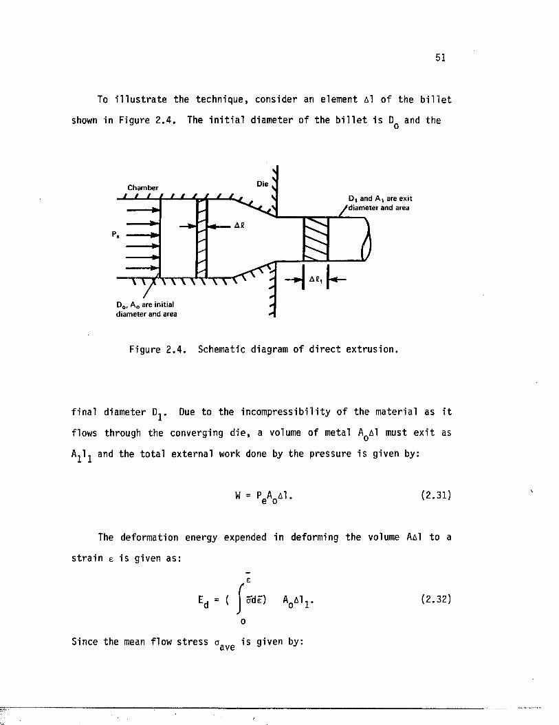
51
To i l l u s t r a t e the technique, consider an element Al of the b i l l e t
shown in Figure 2 .4 . The i n i t i a l diameter of the b i l l e t i s Dq and the
Die ^
A S
ChamberD, and A , are exit
/d ia m e te r and area
A S ,
D0. A 0 are initial d iam ete r and area
Figure 2 .4 . Schematic diagram of d i r e c t ex t rus ion .
f ina l diameter Dj. Due to the incompress ib i l i ty of the materia l as i t
flows through the converging d ie , a volume of metal Aqa1 must e x i t as
A j l j and the to ta l external work done by the pressure i s given by:
W = P eA0Al. (2.31)
The deformation energy expended in deforming the volume AaI to a
s t r a i n e is given as:
e
= ( ^cdeT) ApAlj. (2.32)
0
Since the mean flow s t r e s s a is given by:a VG
52
aave1 e - f ade
* n(2.33)
then:
Ed = (oave W (2.34)
Also, since the deformation i s assumed to be id e a l ly uniform, the
equivalent s t r a i n in the product i s :
by equating the ex ternal work to the energy consumed in deforming the
workpiece, t h i s equation r e s u l t s :
I t r e l a t e s the external pressure of the deforming materia l to the e x t ru
sion r a t i o and to the average s t r e s s of deformation. As mentioned
e a r l i e r , t h i s s im p l i s t i c approach neglec ts f r i c t i o n and provides no
d e t a i l s regarding metal flow.
(2.35)
Therefore:
(2.36)
53
2 .2 .1 .2 Slab analys is
The s lab method, a l so ca l l ed the f ree body equi l ibrium approach,
was developed to c a lc u la te s t r e s s e s and loads by in teg ra t in g the d i f f e r
e n t i a l equation of equil ibr ium under a s im pl i f ied s t r e s s s t a t e . The
assumption of planar sec t ions remaining planar is made and, th e re fo re ,
the deformation i s considered to be homogeneous in regard to the d e t e r
mination of induced s t r a i n . Moreover, although the e f f e c t s of surface
f r i c t i o n are included in the force balance, they d o n ' t inf luence the
in te rna l d i s to r t i o n of the materia l or of the o r i e n ta t io n of pr inc ipal
d i r e c t io n s .
Because of i t s s im p l ic i ty , the s lab method has been applied to many
forming processes. Osakada and Mellor [mm] showed t h a t the required
pressure fo r ex trus ion of a materia l with y ie ld s t r e s s Oy through a
conical die of an included angle a a t an ex trus ion r a t i o R is expressed
as:
P = ov (1 + — — ) (R^Cota - 1 ) + (2.38)pCota 3 i3
where p i s the f r i c t i o n c o e f f i c i e n t between the die and the workpiece.
For small die angles , where pCota < 1» the above equation is s impl i f ied
to:
4aP = o., { (1 + pCota)InR + ——}
y 3/3(2.39)
54
2 .2 .1 .3 Lower bound analys is
This method was developed on the basis of the v a r ia t iona l p r in c ip le
and some cons tra in ing condi t ions . The con t r ibu t ion of f r i c t i o n , fo r
example, i s e n t i r e l y ignored. As the name sugges ts , the analys is pro
vides an underestimate of the exact load from a s t a t i c a l l y admissible
s t r e s s f i e l d . The d e ta i l ed desc r ip t ion o f t h i s theorem is lengthy and
beyond the scope of t h i s study. The reader , however, i s re fe r red to a
book by Prager and Hodge [2.45 ] , in which the lower bound theorem is
presented as:
"Among a l l s t a t i c a l l y admissable s t r e s s f i e l d s , the actual one
maximizes the expression:
where I i s the computed power supplied by the tool over surfaces over
which v e loc i ty i s p rescr ibed ."
In the above equat ion, T̂ are the normal components of surface
t r a c t io n over which v e lo c i ty i s prescr ibed , i . e . , the in te r fa c e between
the ram and the b i l l e t in d i r e c t ex t rus ion . The v.. i s the ram ve loc i ty
in t h a t case.
v
(2.40)
2 .2 .1 .4 Upper bound analys is
The upper bound ana lys is is another technique based on the v a r i a
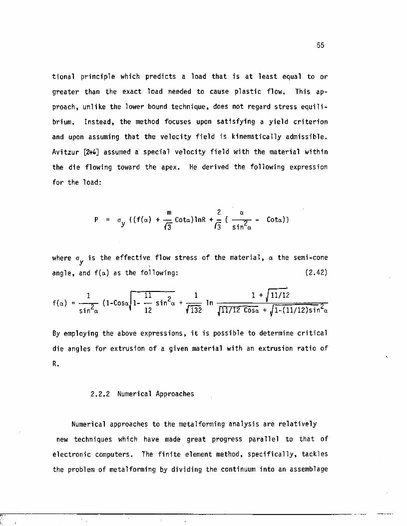
55
t iona l p r inc ip le which p red ic ts a load th a t i s a t l e a s t equal to or
g rea te r than the exact load needed to cause p l a s t i c flow. This ap
proach, unl ike the lower bound technique, does not regard s t r e s s e q u i l i
brium. Ins tead , the method focuses upon s a t i s fy in g a y ie ld c r i t e r i o n
and upon assuming th a t the v e loc i ty f i e l d is kinematically admissible .
Avitzur [2V6] assumed a specia l ve loc i ty f i e l d with the materia l within
the die flowing toward the apex. He derived the following expression
for the load:
m 2 aP = ( ( f (a) + — Cota)lnR + - ( ----- *---------Cota)}
y (2 (3 -Sin a
where a i s the e f f e c t iv e flow s t r e s s of the m a te r ia l , a the semi-coney \
angle, and f ( a ) as the following: (2.42)
1 I H “ 1 1 + 11/12f (a ) = -----5- ( 1-CoSal 1 sin a + In —— ■
S i n a ’ 12 f l 32 ^11/12 Cosa + ^ l - ( l l / 1 2 ) s i n a
By employing the above express ions , i t is possible to determine c r i t i c a l
die angles fo r extrus ion o f a given material with an ext rusion r a t i o of
R.
2 .2 .2 Numerical Approaches
Numerical approaches to the metalforming analys is are r e l a t i v e l y
new techniques which have made grea t progress p a ra l le l to t h a t of
e le c t ro n ic computers. The f i n i t e element method, s p e c i f i c a l l y , tackles
the problem of metalforming by dividing the continuum into an assemblage
56
of d i s c r e t e , q u a d r i la te ra l regions ca l led elements. This numerical
method which has been used in t h i s study is the subjec t of the next
chapter.
f
CHAPTER 3
FINITE ELEMENT ANALYSIS OF METAL FORMING PROCESSES
3.1 INTRODUCTION
The underlying idea of the f i n i t e element method is t h a t any
continuous quan t i ty can be approximated by a s e t o f piecewise continuous
funct ions defined over a number o f components assembled to represent the
quan t i ty . The d i s c r e t i z a t i o n of continuum can be done i n t u i t i v e l y by
c rea t ing an analogy between real d i s c r e te elements and f i n i t e portions
of the continuum domain. In f a c t , the concept of the f i n i t e element
analys is was conceived in the ea r ly 1940s when McHenry [3oi], Hrenikoff
[302] , and Newmark [3os] showed t h a t adequate so lu t ions to a continuum
problem could be obtained by s u b s t i t u t in g an arrangement of simple
e l a s t i c bars fo r small port ions of the continuum. Therefore , i t is from
the view of engineering analogy th a t the term " f i n i t e element" has come
about.
The method had i t s b i r t h in the aerospace indus try in the ea r ly
1950s and was f i r s t presented in the pub l ica t ion by Turner, Clough,
Martin, and Topp [30V]. In f a c t , Clough [?oS] was the f i r s t to use the
term " f i n i t e element," which he defines as "a standard methodology
applicable to d i s c r e te systems." The publ ica t ion by Turner, e t . al in
1956 stimulated o ther researchers and re su l ted in several technical
a r t i c l e s t h a t discussed the app l ica t ion of the method to s t ru c tu ra l and
so l id mechanics.
In 1963, Melosh [3ofe] showed t h a t the f i n i t e element was ac tu a l ly a
57
58
v ar ia t ion of the well-known Raleigh-Ritz procedure. This was an
important th eo re t ic a l con t r ibu t ion and helped numerous o ther researchers
to b e t t e r understand and apply the technique in t h e i r respec t ive f i e ld s
of study.
The connection o f the f i n i t e element method with a minimization
procedure quickly led to i t s extens ive use in structural problems in
which the method produced a s e t o f equil ibrium equations by minimizing
the potentia l energy o f the system. The publ icat ions by Zienkiewicz and
Cheung [30?], Wilson and Nickell [305], and Visser [307] were f i r s t in
showing the applicat ion o f the f i n i t e element method to heat transfer
problems. The applicat ion to f lu id mechanics, par t icu lar ly to the flow
through a porous medium, fol lowed immediately [3/o],
Today a grea t number o f numerical analys ts have turned to f i n i t e
elements, and the technique i t s e l f has advanced from a procedure fo r
solving s t ru c tu ra l problems to a general numerical method fo r solving a
d i f f e r e n t i a l equation or systems of d i f f e r e n t i a l equations . This
advancement has been accomplished in a shor t period of time and has been
a s s i s t ed by the development of high-speed d i g i t a l computers. Currently ,
there are a number of general purpose f i n i t e element programs ava i lab le
th a t are capable of handling problems of any magnitude in v i r t u a l l y
every sec to r o f the engineering d i s c i p l in e . In t h i s work, a non- l inea r ,
large deformation, e l a s t o - p l a s t i c f i n i t e element code, ABAQUS [3/1], has
been used to simulate the hydros ta t ic co-extrus ion of b i -m e ta l l i c
compounds, the analys is o f which is presented in the sec t ions th a t
follow.
59
3.2 THEORY
In the ana lys is of metal forming, the re are two schemes of the
f i n i t e element method. The f i r s t i s the " r i g i d - p l a s t i c , " or "flow"
an a ly s i s , which assumes t h a t the metal i s a non-Newtonian f lu id having a
v i s co - p l a s t i c or r i g i d - p l a s t i c behavior [31/2.]. The second scheme is the
so l id approach, or the e l a s t i c - p l a s t i c analys is [313,3)*/,3)6 ,3 ifa]. The
r i g i d - p l a s t i c assumption i s not f e a s ib le fo r the ana lys is in which the
res idual s t r e s s e s are concerned. This is due to the f a c t th a t in th i s
approach the e l a s t i c deformations are neglec ted , and the s t r a i n or
s t r a i n r a t e components a re only p l a s t i c ones [3 )7] . Large metal
deformations, however, are e l a s t i c - p l a s t i c in nature and are generally
non- l inea r both in mate ria l p roper t ie s and in geometry. The
n o n - l i n e a r i t i e s in such deformations are assoc ia ted with large
displacements involving r i g i d body motions and s t r a in s [3/8].
Lee and McMeeking [ 3IS, 320 ] showed t h a t in most cases of
e l a s t i c - p l a s t i c metal deformation, the e l a s t i c response i s e s s e n t i a l l y
unchanged by p l a s t i c deformation, and the two behaviors can be
considered uncoupled. This is because the e l a s t i c p roper t ie s depend on
the arrangement of atoms in the bulk and are b a s ica l ly unaffected by
moderate p l a s t i c flow, which is due to the movement of d is loca t ions
[32.1]. Therefore, since e l a s t i c and p l a s t i c deformations are due to
d i f f e r e n t processes in the l a t t i c e , i t is j u s t i f i a b l e to separa te them
in the c o n s t i t u t i v e equations governing the e l a s t i c - p l a s t i c deformation
of metals. Before proceeding with these equations, however, a b r i e f
summary of the continuum mechanics is due, and the following sec t ions of
t h i s chapter are devoted to t h i s purpose.
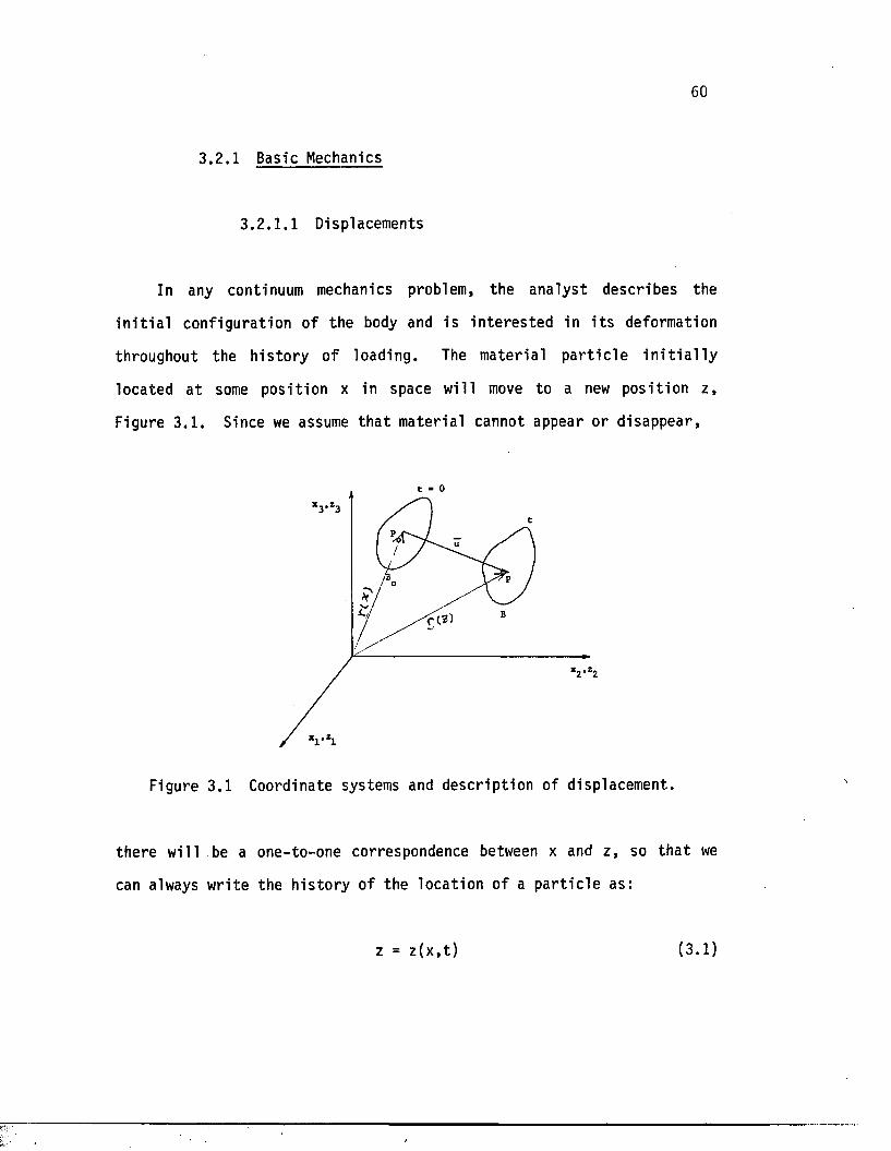
60
3.2 .1 Basic Mechanics
3 .2 .1 .1 Displacements
In any continuum mechanics problem, the ana lys t describes the
i n i t i a l configura tion of the body and i s in t e re s t ed in i t s deformation
throughout the h i s to ry o f loading. The materia l p a r t i c l e i n i t i a l l y
located a t some pos i t ion x in space will move to a new pos i t ion z ,
Figure 3 .1 . Since we assume t h a t materia l cannot appear or disappear,
Figure 3.1 Coordinate systems and desc r ip t ion of displacement.
there wi l l .be a one-to-one correspondence between x and z , so th a t we
can always wri te the h i s to ry of the locat ion of a p a r t i c l e as:
z = z ( x , t ) (3.1)
61
and th i s re la t io n sh ip can be inve r ted , i . e . , we know x when we know z
and t . Therefore,
xi = xi (z1 ,z2 ,z 3 , t ) i = 1,2 ,3 (3.2)
and
Zj = z j (x^ ,x2 »x3 , t ) i - 1,2 ,3 (3.3)
The above transformations are assumed to be s ing le-value and continuous,
provided th a t :
3z.0 < de t . ------ < “ (3.4)
8xj
9ziwhere the — - is the Jacobian.3Xj
Now, depending on whether or not the displacement vector is
associa ted with a point in the o r ig ina l or deformed conf igura t ion , the
components of the displacement vector are given by the following
r e l a t io n s :
u i ( xi , x2»x3) - z.*(xj , x2 , x3) - Xi (3.5)
u^ Z p Z g .Z g ) - z.j - xi ( z 1,z 2 ,z3) (3.6)
The materia l desc r ip t ion o f the ve loc i ty vector is simply the time
der iva t ive of the displacement vector ; thus ,
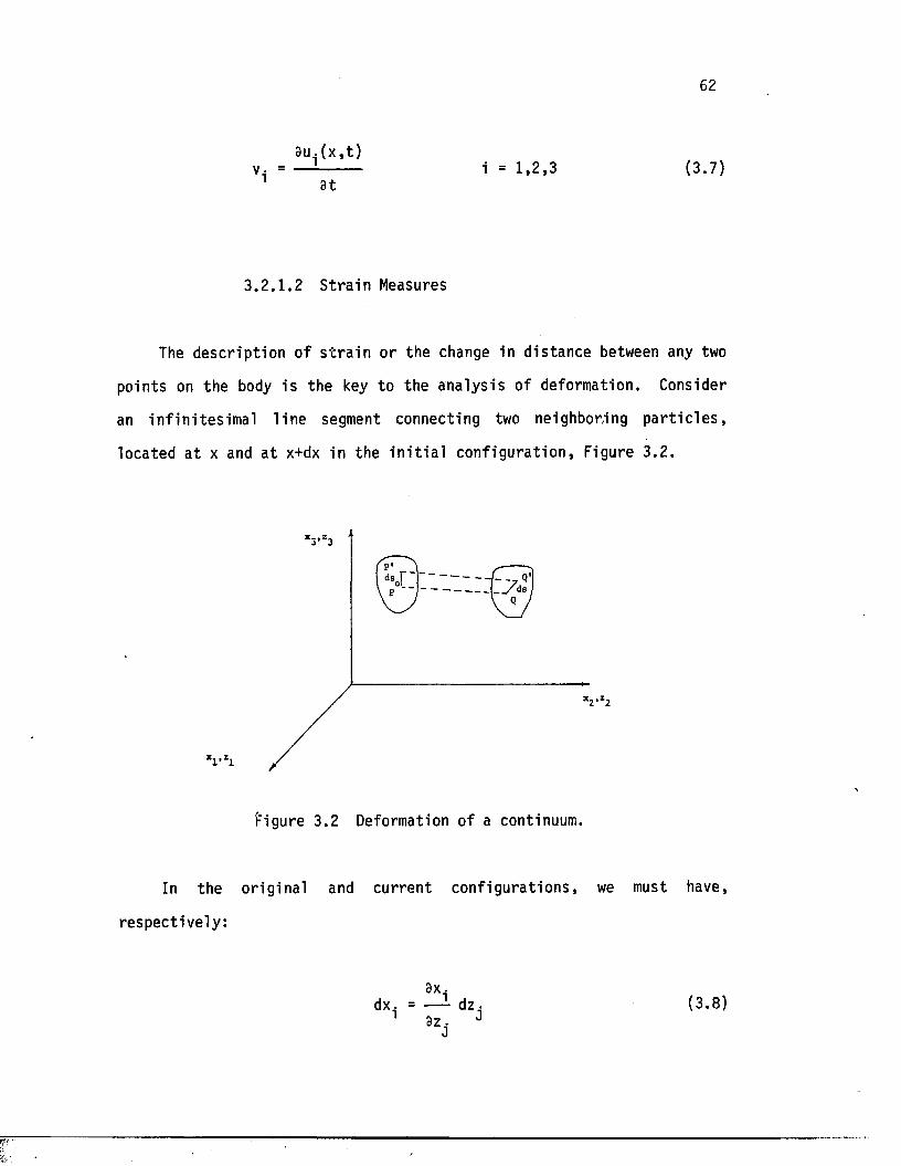
62
a u . ( x , t )V - = — -------- i = 1,2 ,3 (3.7)
1 a t
3 .2 .1 .2 S t r a in Measures
The desc r ip t ion of s t r a i n or the change in d is tance between any two
points on the body i s the key to the ana lys is of deformation. Consider
an in f in i te s im a l l in e segment connecting two neighboring p a r t i c l e s ,
located a t x and a t x+dx in the i n i t i a l conf igu ra t ion , Figure 3.2 .
f igure 3.2 Deformation of a continuum.
In the o r ig inal and curren t conf igura t ions , we must have,
re spec t ive ly :
3x .dx. = — - dz. (3.8)
63
and
3zdz. = — !• dx.
1 9x, JJ
(3 .9)
Also, in the i n i t i a l and cu rren t conf igura t ion , we can wr i te :
? ? ? ? ds„ = dx, + dx0 + dx, o 1 c 3 (3.10)
and
ds2 = d z j2 + dz22 + dz32 (3.11)
or simply:
and
dsQ2 = dx^ ’ dx
ds2 = dz^ ' dz
(3.12)
(3.13)
I t is usual ly important to d is t ingu ish r ig id body motion and s t r a in in g
motion. Therefore, the s t r e t c h of the in f in i tes im al gauge length ds0
is defined as:
ds dzT •-----T-----
dz i
dso dx • dx(3.14)
64
and i f A = 1, there is no s t r a i n involved—the gauge length has
undergone r i g i d body motion only. I f A * 1, however, there i s s t r a i n ,
and in order to define t h i s motion, we may rewri te expressions (3.10)
and (3 .11) , using the Kronecker d e l t a , as:
3x. 3 x .ds = 6 . -dx-dx . = 6 —1 dz dz (3.15)
o i j i j 'J j z 3Z ' =>r s
and
3z. 3z •ds = 6. .dz .dz. = 6 . . i dx dx (3.16)g g r S>
Useful r e s u l t s are obtained by sub t rac t ing the expressions (3.10) and
(3.11) from one another ; th e re fo re ,
? o 3zds - dso = (6r s ----------------6i j } dxi dxj
° * 3 X • 3 X . J J* J
(3.17)
or
o p ^ X _d S - ds0 = <6, . - 6rs — — ) d ^ d l j (3.18)
We define the s t r a i n tensors :
65
3Za 9zh e . . = i (6 _ 1 - 6 . . )1J r s 9x. 3x. 1J
' J
(3 .19 )
and
9xr 3xsh . . = i ( « . . - « )U U rsi J
(3.20)
so t h a t :
ds2 - dso2 ' 2e1j dxi dxj (3.21)
and
ds - d s 0 = 2 h , j dz ,dZ j (3.22)
The s t r a i n tensor e - • i s the materia l desc r ip t ion of a s t r a in" J
tenso r and i s known as Green's s t r a i n t enso r , while h . . i s the spa t ia l* J
form of the s t r a i n tensor and is ca l led Cauchy's or Almansi 's s t r a in
tensor .
Using the components of the displacement vector u, and the
r e l a t i o n s :
9z„ 9u= — - + 6 . ,
9x. 9X. r i
9x 9ur & __r9Z. " n ‘ " 9X. 1 1
(3 .23 )
66
these forms of the s t r a i n tensors may be wr i t t en as:
e i j " *311 • 3U • 3U 3 U ,
J 1 ^ Q Q3 x i 3Xj ax^ 3Xj (3.24)
and
- *3U • 3U • 3U 3U
J .j. * ^ “ Q3 Z . 3 2 . 3 Z . 3 Z . (3.25)
In the unabridged nota tion (x ,y ,z fo r Xj.XgjXgj and u,v,w for
u ^ ^ s U ^ ) , the Green's s t r a i n tensor exx i s expressed as:
3 U 1 e = — + —
X X 3 X 2
2 2 3 U 3 V
ax ay
3 W
3 Z(3.26)
Designating e^ as the measure of extension per un i t undeformed length ,
or
ds - ds.e l = ds.
(3.27)
then e^ can be re l a t e d to the mater ia l s t r a i n tensor by the expression:
e = (2en + 1)* - 1 (3.28)
67
dvic s t r a i n
s t r a i n tenso r ; as
The volumetric s t r a i n clv^ i s expressed in terms of the material
dV = J (3.29)dV_
where J is the Jacobi an and is expressed as:
J = (1 + 21 + 4 I I e + 8 I I I e )* (3.30)
where I , II , and I I I are the f i r s t , second, and t h i r d s t r a in e e ein v a r ia n t s , r e sp ec t iv e ly , and are defined as:
1e ~ eAAI I e = l / 2 ( e AAe BB - eC[)eCD) (3.31)
m e = 1 /6( 2eABeBCeCA " 3eEFeEFeMM + eNNePPeQQ^
3 .2 .1 .3 S t ra in Rates
The materia l s t r a i n r a t e tensor is the time d e r iva t ive of the
mater ia l s t r a i n tensor and i s defined as:
3e
e i j =i j
3t
3 V • 3 V •— I + — 13 X ■ 3 X •
J *
(3.32)
68
where:
Dt(ds2 - dsQ2) = 2e..j dx^x^ (3.33)
Sim i la r ly , the sp a t i a l s t r a in r a t e tensor i s the time de r iva t ive of
the s p a t i a l s t r a i n tensor and is expressed as:
h i j 9t 23Vi 9Vj, 9 2 . 9 Z .
(3.34)
where:
Dt(ds2 - ds02) ■= 2 h , . d Z l d Z j (3.35)
The materia l and s p a t i a l s t r a in r a t e tensors are r e la ted through
the expression:
9Z. gz-i
= " kl’ J
(3.36)
3 .2 .1 .4 S t ress Measures and Stress Rates
Referring to Figure 3 .3 , the materia l s t r e s s vector defined
as the surface force per un i t area in the undeformed body, may be
expressed in terms of t ^ j as follows:
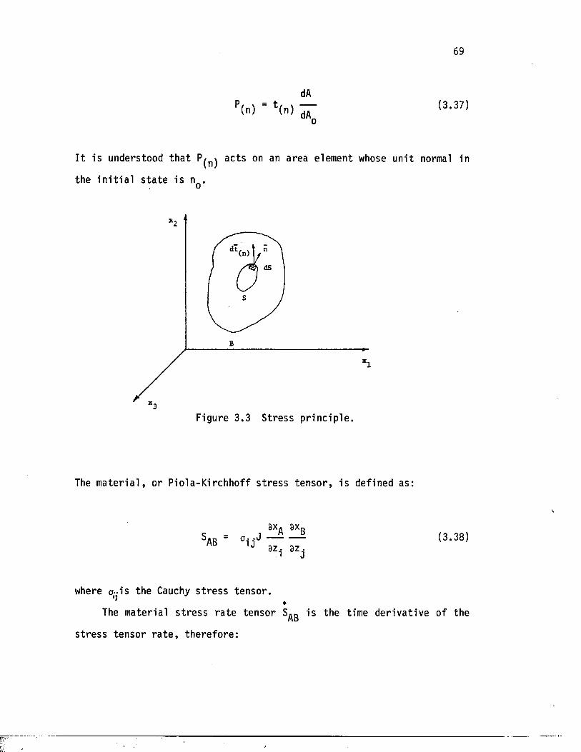
69
P(n) = *(n)dA
dA_(3.37)
I t i s understood th a t ac ts on an area element whose un i t normal in
the i n i t i a l s t a t e i s nQ.
(n)
Figure 3.3 S tress p r in c ip le .
The m a te r i a l , or P iola-Kirchhoff s t r e s s t en so r , is defined as:
ax. ax„SAB = ou J — — (3.38)
3Z, 82j
where a--is the Cauchy s t r e s s tensor .
The materia l s t r e s s r a t e tensor S^g i s the time de r iva t ive of the
s t r e s s tensor r a t e , the re fo re :
3 .2 .2 Governing Equations fo r E l a s to -p la s t i c Deformation
The fundamental equation which describes the mechanics of
e l a s t o - p l a s t i c deformation i s the Lagrangean desc r ip t ion of the r a te
equation given by the expression
where [ s ] is the materia l r a t e of the unsymmetric nominal s t r e s s tensor
or the f i r s t Pio lo-Kirchhoff s t r e s s tenso r ; {b}, the body force
i n t e n s i ty vector ; and {f} , the surface t r a c t io n vector . In the above
equation, a l l in teg ra t io n s are performed in the re fe rence conf igura t ion .
In the Eulerian d esc r ip t ion of the deformation, however, the motion is
described in terms of t rue s t r e s s and t ru e s t r a i n , both of which are
defined with re spec t to an Eulerian or cu r ren t re fe rence frame. This is
a more appropr ia te way of s t a t i n g the r a t e equation since the laws of
p l a s t i c i t y are usually formulated with reference to the current
conf igura tion ( ) . The scheme t h a t is most popular among the
researchers in the f i e l d of la rge incremental metal deformation,
however, is the "updated Lagrangean" scheme, in which the s t a t e a t a
time t is taken as the re fe rence fo r displacements t h a t occur a t time
t+At ( ) . This updated Lagrangean desc r ip t ion of equation 3.40, as
(3.40)
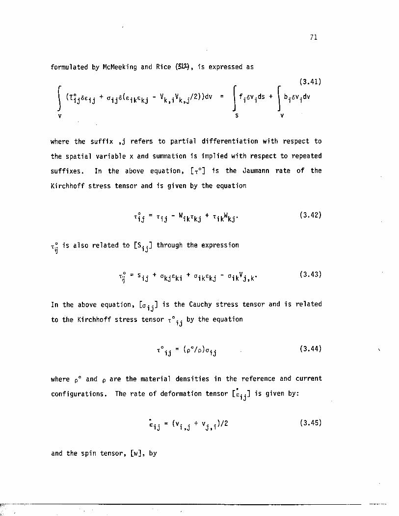
71
formulated by McMeeking and Rice (3W), is expressed as
(3 .41 )
(Ti j 6ei j + ° i j fi{eikekj ' Vk , i Vk , j /2))dv = f.fiv.ds + I b.fiv-dv
where the su f f ix , j r e f e r s to p a r t i a l d i f f e r e n t i a t i o n with respec t to
the sp a t i a l va r iab le x and summation is implied with respec t to repeated
su f f ix e s . In the above equat ion, [ T°] is the Jaumann r a t e of the
Kirchhoff s t r e s s tensor and is given by the equation
t?,- - !,• i - W. .T. . + t-ii-W... ( 3 . 42)ri j Ti j i k Tkj Tik kj '
T° i s a lso re la ted to [ S . . ] through the expression ij ' J
In
TIj = s i j + ak jeki + a ik ekj ' ° i k Vj , k ‘ (3 ‘43)
the above equat ion, i s the Cauchy s t r e s s tensor and i s re la ted* «J
to the Kirchhoff s t r e s s tensor T° i • by the equation■ J
T°1j = ( P0 /P)a i j (3 -44)
where p° and p are the materia l d e n s i t i e s in the reference and curren t
conf igura t ions . The r a t e o f deformation tensor i s given by:' J
'ei j ■ (vi . j + vj , i ) /2 (3 -45)
and the spin tenso r , [w], by
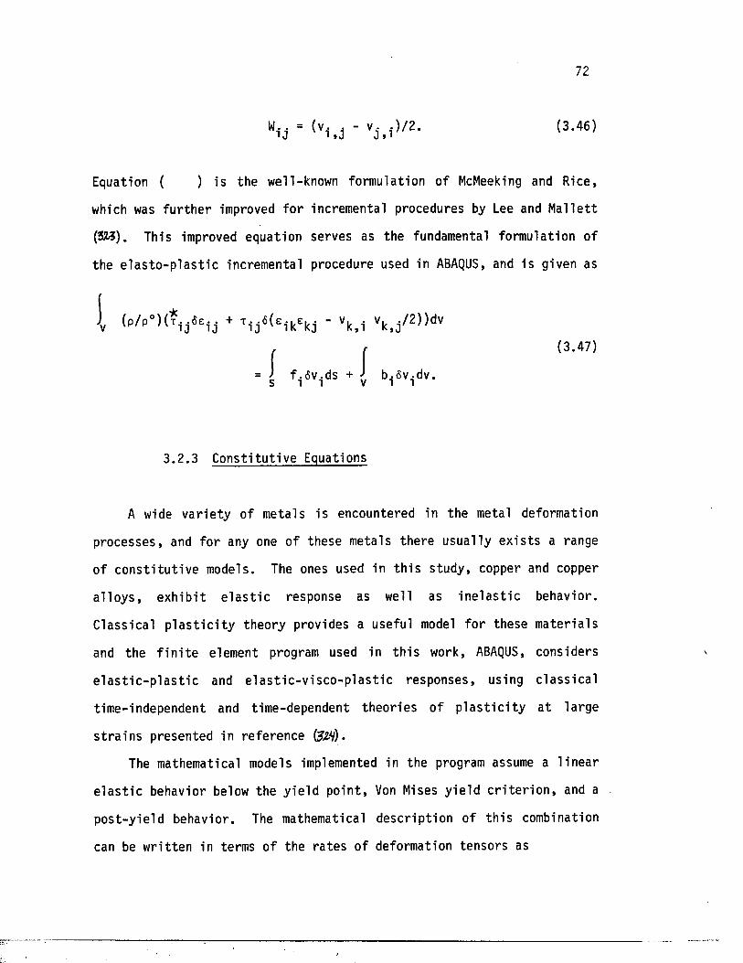
72
(3 .46 )
Equation ( ) is the well-known formulation of McMeeking and Rice,
which was fu r th e r improved fo r incremental procedures by Lee and Mal le t t
(32/3). This improved equation serves as the fundamental formulation of
the e l a s t o - p l a s t i c incremental procedure used in ABAQUS, and is given as
A wide v a r ie ty of metals is encountered in the metal deformation
processes , and fo r any one of these metals there usually e x i s t s a range
of c o n s t i t u t i v e models. The ones used in t h i s study, copper and copper
a l l o y s , e x h ib i t e l a s t i c response as well as i n e l a s t i c behavior.
Class ical p l a s t i c i t y theory provides a useful model fo r these mater ia ls
and the f i n i t e element program used in t h i s work, ABAQUS, considers
e l a s t i c - p l a s t i c and e l a s t i c - v i s c o - p l a s t i c responses, using c la s s i c a l
time-independent and time-dependent theor ie s o f p l a s t i c i t y a t large
s t r a i n s presented in reference (3&V).
The mathematical models implemented in the program assume a l in e a r
e l a s t i c behavior below the y ie ld po in t , Von Mises y ie ld c r i t e r i o n , and a
pos t -y ie ld behavior. The mathematical desc r ip t ion of th i s combination
can be wr i t t en in terms of the r a te s of deformation tensors as
v,, , /2 ) )dv
(3.47)
3 .2 .3 Cons t i tu t ive Equations
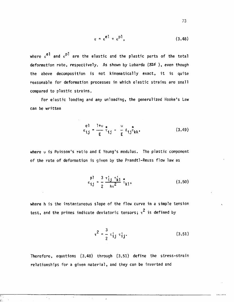
73
e = ee ̂ + , (3.48)
where ee ̂ and are the e l a s t i c and the p l a s t i c pa r t s of the to ta l
deformation r a t e , re sp ec t iv e ly . As shown by Lubarda (32£ ) , even though
the above decomposition is not kinematica lly exac t , i t is qu i te
reasonable fo r deformation processes in which e l a s t i c s t r a in s are small
compared to p l a s t i c s t r a i n s .
For e l a s t i c loading and any unloading, the generalized Hooke's Law
can be wr i t t en
el 1+u * u *
! i j ' T TU ' i V k k ’ (3 ' 49)
where u i s Poisson 's r a t i o and E Young's modulus. The p l a s t i c component
of the r a t e of deformation is given by the Prandtl-Reuss flow law as
Pl 3 t i j ,(3.50)
where h i s the instantaneous slope of the flow curve in a simple tension
t e s t , and the primes ind ica te d ev ia to r ic t enso rs ; t is defined by
2 3x = - t '. . t ! .. (3.51)l j i j
Therefore , equations (3.48) through (3.51) def ine the s t r e s s - s t r a i n
re la t ionsh ips fo r a given m a te r ia l , and they can be inverted and
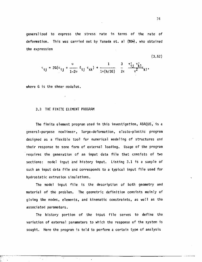
74
generalized to express the s t r e s s r a t e in terms of the r a te of
deformation. This was ca r r ied out by Yamada e t . al (32U), who obtained
the expression
(3.52)
u 1 3 t ! T't . . = 2G(e. + ----------- 6 . . e . . ) + --------------------- - -----------* — e. , ,
i j i j j_2u i j kk l+(h/3G) 2e x Kl
where G is the shear modulus.
3.3 THE FINITE ELEMENT PROGRAM
The f i n i t e element program used in t h i s in v e s t ig a t io n , ABAQUS, is a
general-purpose nonl inear , la rge-deformation, e l a s t o - p l a s t i c program
designed as a f l e x ib le tool fo r numerical modeling of s t ru c tu re s and
t h e i r response to some form of external loading. Usage of the program
requires the generation o f an input data f i l e th a t cons is t s o f two
sec t ions : model input and h is to ry input. L is t ing 3.1 i s a sample of
such an input data f i l e and corresponds to a typica l input f i l e used for
hydros ta t ic extrusion simula tions.
The model input f i l e is the desc r ip t ion of both geometry and
materia l of the problem. The geometric d e f in i t io n cons is t s mainly of
giving the nodes, elements, and kinematic c o n s t r a in t s , as well as the
assoc ia ted parameters.
The h is to ry port ion of the input f i l e serves to define the
v a r ia t ion of external parameters to which the response of the system is
sought. Here the program is to ld to perform a ce r ta in type of analys is
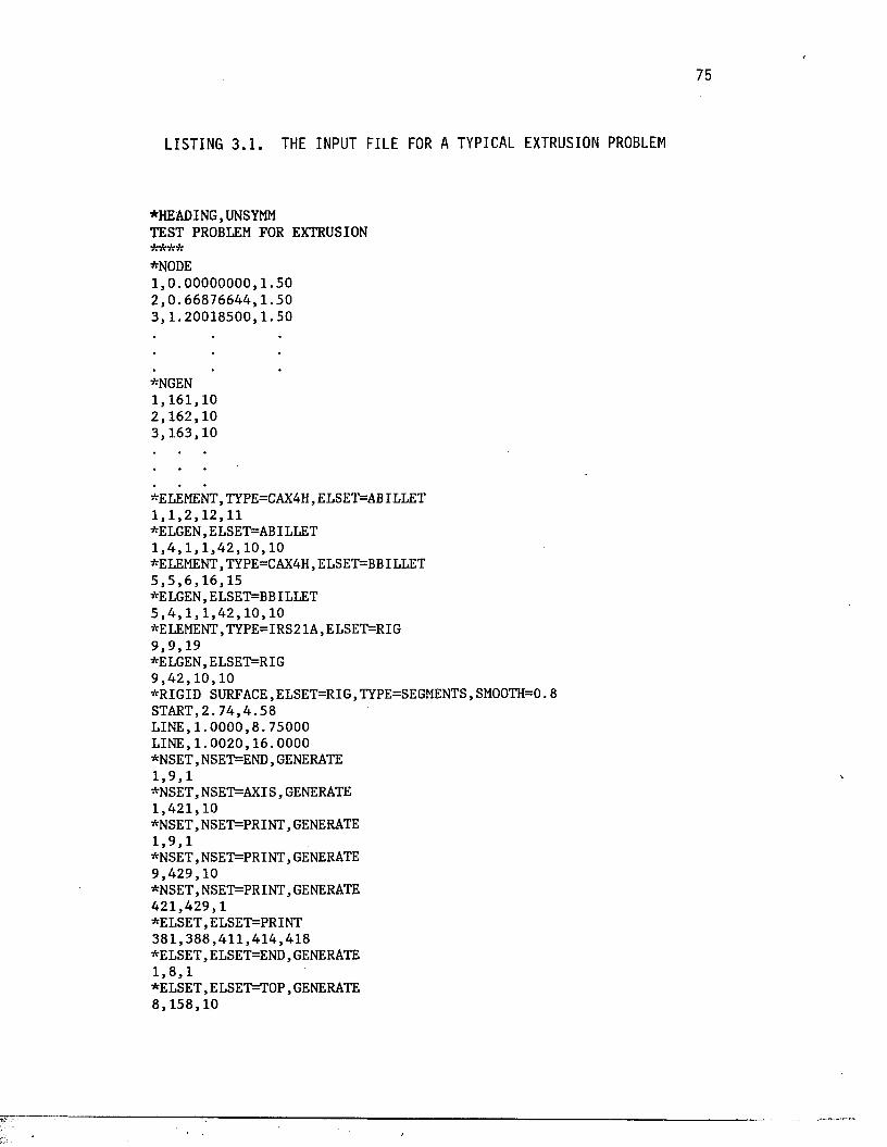
LISTING 3 .1 . THE INPUT FILE FOR A TYPICAL EXTRUSION PROBLEM
*HEADING, UNSYMMTEST PROBLEM FOR EXTRUSION
*NODE1 . 0 . 0 0 0 0 0 0 0 0 . 1 . 5 02 . 0 . 6 6 8 7 6 6 4 4 . 1 . 5 0 3 , 1 . 2 0 0 1 8 5 0 0 , 1 . 5 0
*NGEN1 , 1 6 1 , 1 02 , 1 6 2 , 1 03 , 1 6 3 , 1 0
*ELEMENT,TYPE=CAX4H,ELSET=ABILLET 1 , 1 , 2 , 1 2 ,11 *ELGEN, ELSET=ABILLET1 . 4 . 1 . 1 . 4 2 . 1 0 . 1 0*ELEMENT, TYPE=CAX4H, ELSET=BBILLET5 , 5 , 6 , 1 6 , 1 5*ELGEN, ELSET=BBILLET5 . 4 . 1 . 1 . 4 2 . 1 0 . 1 0 *ELEMENT,TYPE=IRS21A,ELSET=RIG 9 , 9 , 1 9*ELGEN,ELSET=RIG9 . 4 2 . 1 0 . 1 0* R IG ID SURFACE, ELSET=RIG,TYPE=SEGMENTS, SMOOTH=0. 8S TA R T,2 . 7 4 , 4 . 5 8L I N E , 1 . 0 0 0 0 , 8 . 7 5 0 0 0L I N E , 1 . 0 0 2 0 , 1 6 . 0 0 0 0*N SET, NSET=END, GENERATE1 . 9 . 1*NSET,NSET=AXIS, GENERATE1 . 4 2 1 . 1 0*NSET,NSET=PRINT,GENERATE1 . 9 . 1*N SET, NSET=PRINT, GENERATE9 . 4 2 9 . 1 0*N SET, NSET=PRINT, GENERATE4 2 1 . 4 2 9 . 1*ELSET,ELSET=PRINT 3 8 1 , 3 8 8 , 4 1 1 , 4 1 4 , 4 1 8 * E L SE T , ELSET=END, GENERATE1 .8 . 1*ELSET,ELSET=TO P, GENERATE8 . 1 5 8 . 1 0
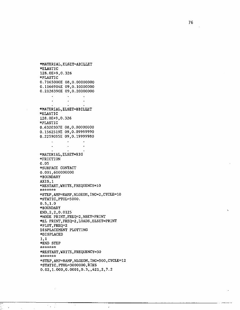
♦MATERIAL,ELSET=ABILLET♦ELASTIC1 2 8 . O E + 9 ,0 . 3 2 6♦PLASTIC0 . 7 1 6 5 0 0 0 E 0 8 , 0 . 0 0 0 0 0 0 0 0 0 . 1 1 6 6 9 0 4 E 0 9 , 0 . 1 0 0 0 0 0 0 0 0 . 2 1 2 6 3 9 0 E 0 9 , 0 . 2 0 0 0 0 0 0 0
♦MATERIAL, ELSET=BBILLET♦ELASTIC1 2 8 . O E + 9 ,0 . 3 2 6♦PLASTIC0 . 6 3 2 0 3 0 7 E 0 8 , 0 . 0 0 0 0 0 0 0 0 0 . 1 5 6 2 5 1 9 E 0 9 , 0 . 0 9 9 9 9 9 9 0 0 . 2 2 5 9 0 9 5 E 0 9 , 0 . 1 9 9 9 9 9 8 0
♦MATERIAL,ELSET=RIG♦FRICTIO N0 . 0 5♦SURFACE CONTACT 0 . 0 0 1 , 6 0 0 0 0 0 0 0 0 ♦BOUNDARY A X I S , 1♦RESTART, WRITE, FREQUENCY=10 * * * * * * *
♦ S T E P , AMP=RAMP, NLGEOM, IN C = 2 , CYCLE=10 ♦ S T A T IC , P T O L = 5000 .0 . 5 , 1 . 0 ♦BOUNDARY EN D,2 , 2 , 0 . 0 1 2 5♦NODE P R IN T ,FR EQ = 2, NSET=PRINT ♦EL PRINT,FREQ=2,LOADS,ELSET=PRINT ♦PLOT,FREQ=2 DISPLACEMENT PLOTTING ♦DISPLACED1 , 1♦END STEP * * * * * * *
♦RESTART, WRITE, FREQUENCY=30 * * * * * * *
♦STEP,AMP=RAMP, NLGEOM,INC=500, CYCLE=12 ♦S T A T IC , P T O L = 3 0 0 0 0 0 0 , RIKS 0 . 0 2 , 1 . 0 0 0 , 0 . 0 0 0 1 , 0 . 3 , , 4 2 1 , 2 , 7 . 2
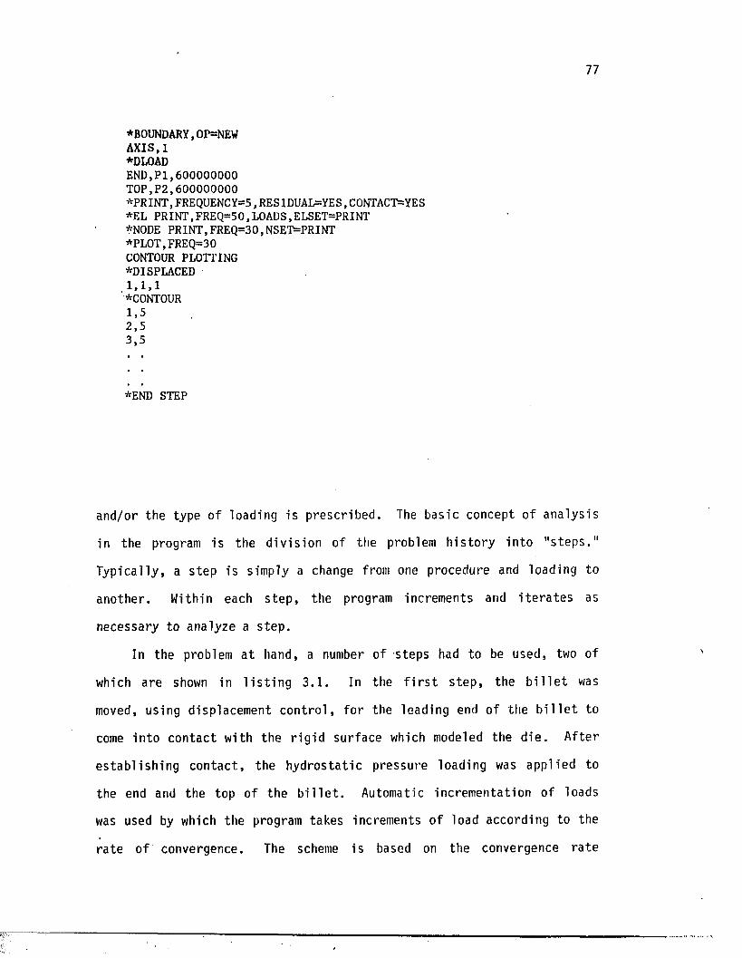
77
*BOUNDARY,OP=NEWA X I S , 1*DLOADE N D , P I , 6 0 0 0 0 0 0 0 0 T O P , P 2 , 6 0 0 0 0 0 0 0 0*PRINT,FREQUENCY=5, RESIDUAL=YES, CONTACT=YES *EL P R IN T , FREQ=50,LOADS, ELSET=PRINT *N0DE PRIN T,FR EQ =30,N SET=PR IN T *PLOT,FREQ =30 CONTOUR PLOTTING *DISPLACED1 , 1, 1 *CONTOUR1.52 . 53 . 5
*END STEP
and/or the type of loading i s prescr ibed . The basic concept of analys is
in the program is the d iv is ion of the problem h is to ry in to " s t eps ."
Typically , a s tep is simply a change from one procedure and loading to
another . Within each s t e p , the program increments and i t e r a t e s as
necessary to analyze a s tep .
In the problem a t hand, a number of steps had to be used, two of
which are shown in l i s t i n g 3 .1 . In the f i r s t s t ep , the b i l l e t was
moved, using displacement co n t ro l , fo r the leading end of the b i l l e t to
come in to contac t with the r ig id surface which modeled the d ie . After
e s tab l i sh in g con tac t , the hydros ta t ic pressure loading was applied to
the end and the top of the b i l l e t . Automatic incrementation of loads
was used by which the program takes increments of load according to the
r a te of convergence. The scheme is based on the convergence ra te
78
observed in the i t e r a t i o n process a t each increment. After four
i t e r a t i o n s , the program checks the convergence r a t e and estimates i f
convergence i s l i k e ly with in the maximum number of i t e r a t i o n s allowed.
I f no t , the increment s ize i s reduced by a f a c to r of four . I f , on the
o ther hand, the convergence is achieved in le ss than one h a l f of the
maximum number of i t e r a t i o n s allowed, the increment s ize is increased by
a f a c to r of 1.5. This process is continued u n t i l the maximum value of
the load i s achieved, or u n t i l the ana lys is i s completed.
The procedure " input options" of the program provides the
d e f in i t io n of the type of ana lys is needed to obta in the response of any
s t ru c tu re under an external loading. S t a t i c analys is is used in
hydros ta t ic extrusion problems due to the f a c t t h a t i n e r t i a e f f e c t s are
i n s ig n i f i c a n t . Because of n o n l in e a r i ty , however, the analys is requires
the so lu t ion of nonlinear equil ibr ium equat ions . This is normally done
using Newton's method. In the case of ex trus ion problems, however,
t h i s technique i s not e f f i c i e n t and often f a i l s in the neighborhood of
c r i t i c a l po in ts . The modified Riks' a lgor ithm, of fered by the program,
is one way of t rac ing nonlinear response from the p re - l im i t in to the
p o s t - l im i t range. I t chooses increments based on c on t ro l l ing the path
length along the load-displacement response curve, and thus obta ins
so lu t ions regard less of whether the response is s tab le or unstable .
Deta il s of the modified Riks' method are presented in a paper by E. Ramm
(KS).
3.4 SIMULATION PARAMETERS
The problem was t r e a te d axisymmetrically and th e re fo re , ha l f of the
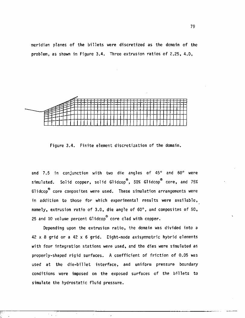
79
meridian planes of the b i l l e t s were d i s c re t i ze d as the domain of the
problem, as shown in Figure 3 .4 . Three ext rusion r a t i o s of 2.25, 4 .0 ,
Figure 3 .4 . F in i te element d i s c r e t i z a t i o n o f the domain.
and 7.5 in conjunction with two die angles of 45° and 60° were
simulated. Solid copper, so l id Glidcop®, 50% Glidcop® core , and 75%<5)Glidcop core composites were used. These simulation arrangements were
in addit ion to those fo r which experimental r e s u l t s were a v a i l ab le ,
namely, ext rusion r a t i o o f 3 .0 , die angle of 60°, and composites o f 50,
25 and 10 volume percent Glidcop core clad with copper.
Depending upon the extrusion r a t i o , the domain was divided in to a
42 x 8 gr id or a 42 x 6 g r id . Eight-node axisymmetric hybrid elements
with four in teg ra t ion s t a t io n s were used, and the dies were simulated as
properly-shaped r ig id sur faces . A c o e f f i c i e n t of f r i c t i o n o f 0.05 was
used a t the d i e - b i 1 l e t i n t e r f a c e , and uniform pressure boundary
conditions were imposed on the exposed surfaces of the b i l l e t s to
simulate the hydros ta t ic f lu i d pressure .
80
The materia l p roper t ie s o f Glidcop were determined by a s e r ie s of
t e s t s in which samples of the mater ia l were machined and t e s t ed in a
tension machine. A sa tu ra t ion - type equation of the form
O = os - (os - crm) exp (—— (--------1)) (3.53)a s°m em
was used to obtain the flow curve where a g i s the sa tu ra t ion s t r e s s and
a and e are the s t r e s s and s t r a i n of maximum load. For copper, values m m 'of 141.8 Mpa, 115.19 Mpa, and 0.2884 were used fo r a s , am, and em,
re sp ec t iv e ly . Glidcop® and copper have the same modulus of e l a s t i c i t y ,
and a value o f 128 GPA was used fo r both. Also, Poisson's r a t i o of both
m ater ia ls was assumed to be 0.326.
CHAPTER 4
HYDROSTATIC EXTRUSION EXPERIMENTS
4.1 INTRODUCTION
Presented in t h i s chapte r are a desc r ip t ion of the hydros ta t ic
ex trus ion experiments as well as the res idual s t r e s s measurements
conducted a t the Westinghouse Research & Development Center, P i t t sburgh ,
Pennsylvania. The d e t a i l s of these experiments are based on the repor t
by Iyer , Lovic, and Male [40/]. The re s idual s t r e s s measurements were
ca r r ied out using Sachs' boring-out method, which assures a contro l led
metal removal r a te without damaging the specimen.
4.2 HYDROSTATIC EXTRUSION EXPERIMENTS
4.2 .1 Experimental F a c i l i t i e s
Figure 4.1 shows a schematic diagram of the Bridgman-Birch v e r t i c a l
ex trus ion press used in the ex trus ion experiments. The press was
equipped with a 38-mm chamber capable o f withstanding pressures up to 765
Mpa. Also, a v e r s a t i l e hydraulic system f a c i l i t a t e d the use of constant
ram v e lo c i t i e s of up to 15 mm/sec. The ram v e loc i ty was con tro l led in
the experiment by a pressure-compensating system component of the press.
This assured " s t i ck s l i p " - f r e e ex t ru s ions . A l in e a r and a pressure
transducer input module, a t ransduce r -am pl i f i e r , and a l im i t control
output module were among the a u x i l i a ry instruments of the press .
Dies used in the experiments were fab r ica ted from A2 tool s tee l and
81
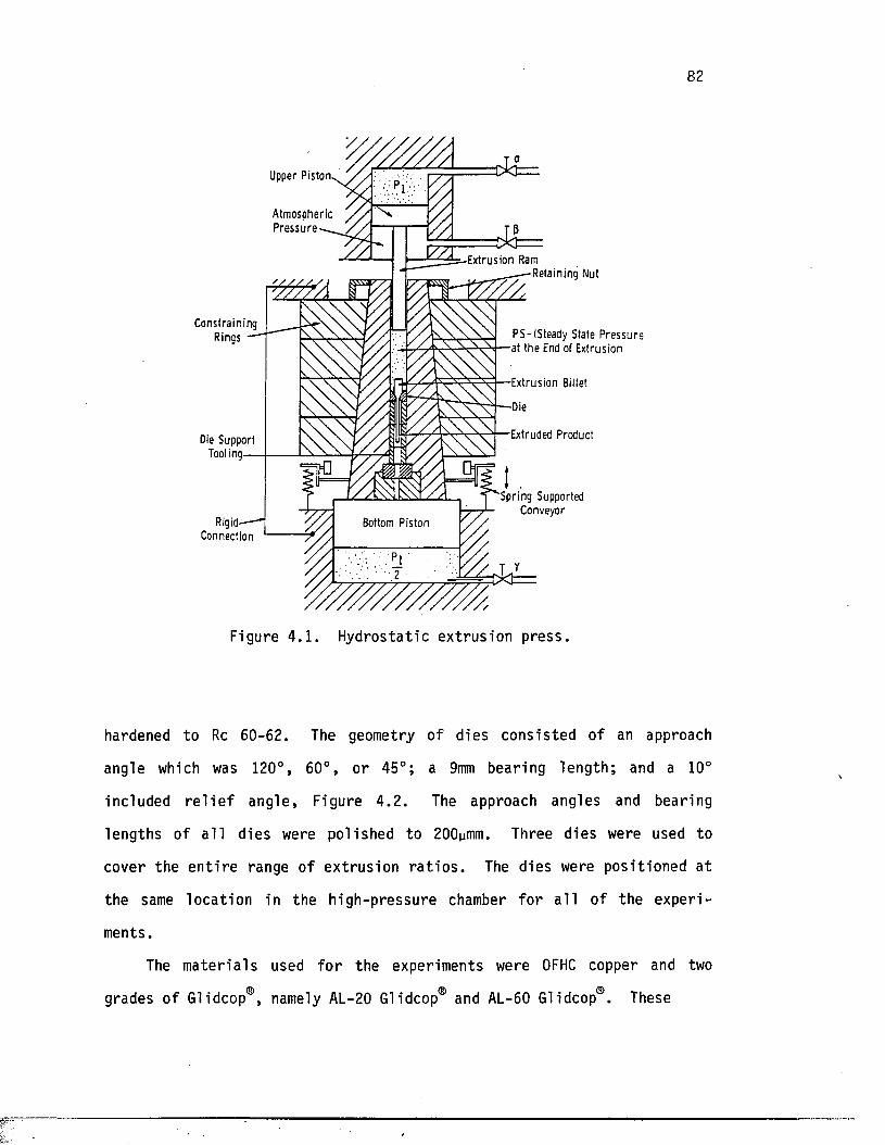
U pper P i s t o n
A tm o s p h e r i c P r e s s u r e
C o n s t r a i n i n g R in g s
Die S u p p o r t Tooling
Rigid' C o n n e c t io n
Bottom P i s t o n
E x t r u s i o n Ram— - R e ta i n i n g N ut
P S - ( S t e a d y S ta te P r e s s u r e a t t h e End of E x t r u s i o n
E x t r u s i o n Billet
Die
E x t ru d e d P r o d u c t
S p r i n g S u p p o r te d y y C o n v e y o r
Figure 4 .1 . Hydrostatic ext rusion press .
hardened to Rc 60-62. The geometry of dies consis ted of an approach
angle which was 120°, 60°, or 45°; a 9mm bearing length ; and a 10°
included r e l i e f angle, Figure 4 .2 . The approach angles and bearing
lengths of a l l dies were polished to 200umm. Three dies were used to
cover the e n t i r e range of ex trus ion r a t i o s . The dies were posit ioned a t
the same locat ion in the high-pressure chamber fo r a l l of the exper i
ments.
The m ate r ia ls used fo r the experiments were OFHC copper and two
grades of Glidcop®, namely AL-20 Glidcop® and AL-60 Glidcop®. These
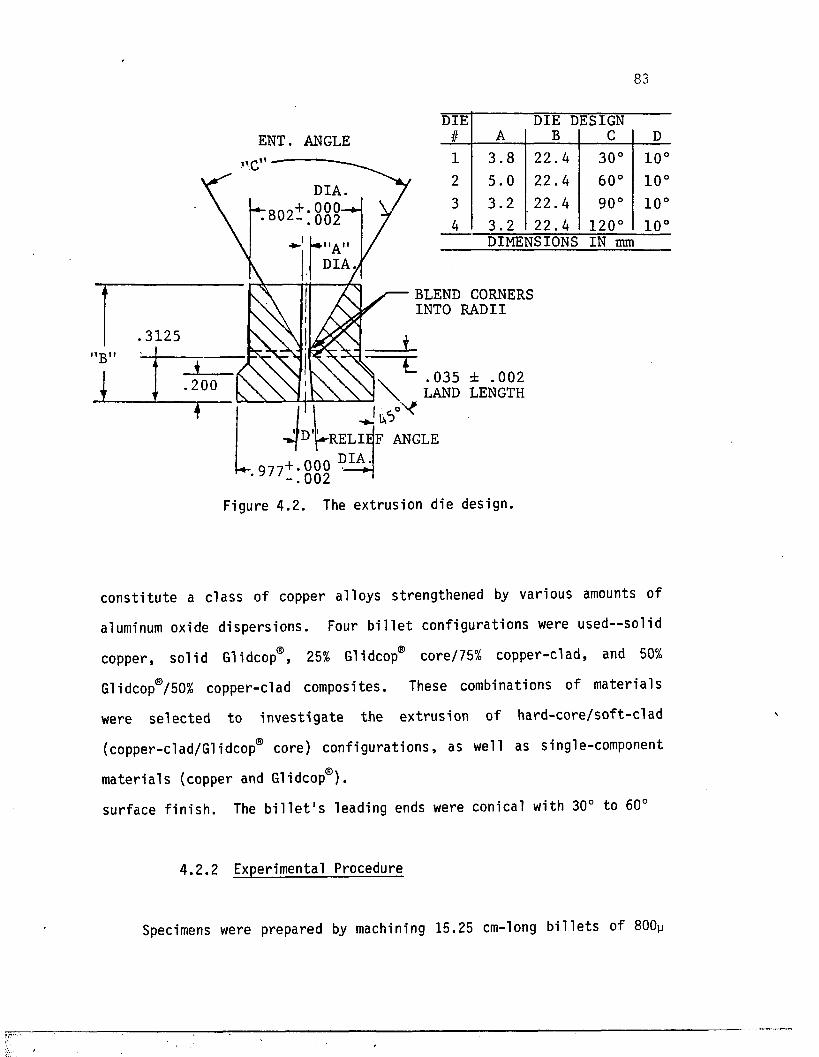
83
ENT. ANGLE, n ,
on0+ .0 0 0 8 02- . 0 0 2
RELIE F ANGLE
+ . 0 0 0 ■
DIE DIE DESIGN# A B C D
1 3 . 8 2 2 . 4 3 0 ° 1 0 °2 5 . 0 2 2 . 4 6 0 ° 1 0 °
3 3 . 2 2 2 . 4 9 0 ° 1 0 °4 3 . 2 f 2 2 . 4 1 2 0 ° 1 0 °
DIMENSIONS IN mm
BLEND CORNERS INTO RADII
. 0 3 5 ± .002 LAND LENGTH
. 002
Figure 4 .2 . The extrus ion die design.
c o n s t i tu t e a c las s of copper a l loys st rengthened by various amounts of
aluminum oxide d i spe r s ions . Four b i l l e t conf igura tions were used—sol id
copper, so l id Glidcop®, 25% Glidcop® core/75% copper-clad, and 50%
Glidcop®/50% copper-clad composites. These combinations of mater ia ls
were se lec ted to in v e s t ig a te the ex trus ion of ha rd -co re / so f t -c lad
(copper-clad/Glidcop® core) conf igura t ions , as well as single-component
m ate r ia l s (copper and Glidcop®).
surface f i n i s h . The b i l l e t ' s leading ends were conical with 30° to 60°
4 .2 .2 Experimental Procedure
Specimens were prepared by machining 15.25 cm-long b i l le t s o f 800y
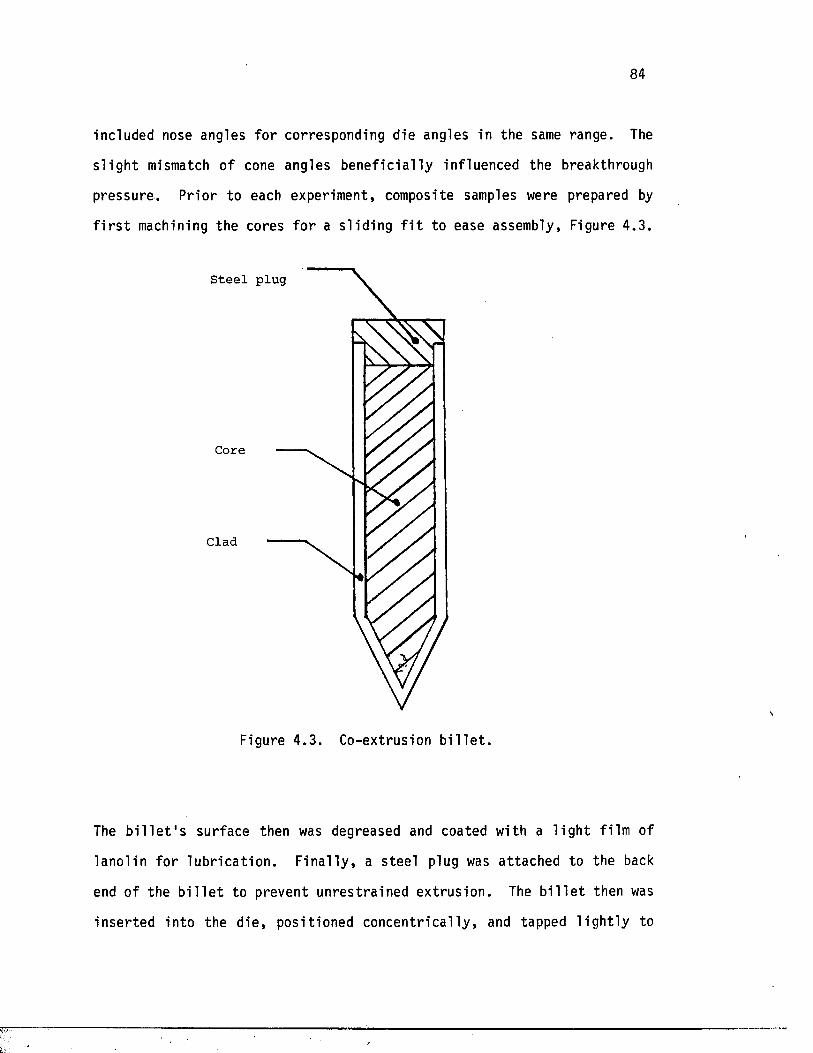
84
included nose angles fo r corresponding die angles in the same range. The
s l i g h t mismatch of cone angles b e n e f ic i a l ly influenced the breakthrough
pressure . P r io r to each experiment, composite samples were prepared by
f i r s t machining the cores f o r a s l id in g f i t to ease assembly, Figure 4 .3 .
Steel plug
Core
Clad
Figure 4 .3 . Co-extrusion b i l l e t .
The b i l l e t ' s surface then was degreased and coated with a l i g h t f ilm of
lano l in fo r lu b r i ca t io n . F in a l ly , a s tee l plug was a ttached to the back
end of the b i l l e t to prevent unres t ra ined ex trus ion . The b i l l e t then was
in se r ted in to the d ie , posit ioned co n cen t r ic a l ly , and tapped l i g h t l y to
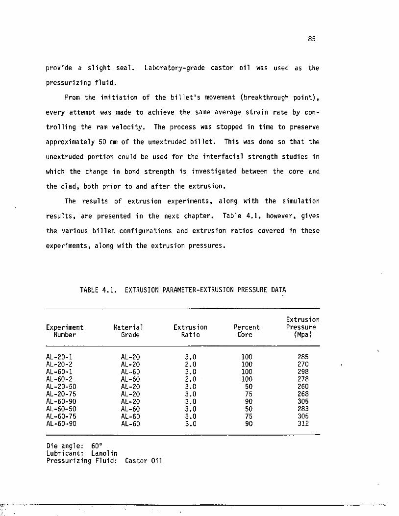
85
provide a s l i g h t s ea l . Laboratory-grade cas to r o i l was used as the
pressur iz ing f l u i d .
From the i n i t i a t i o n of the b i l l e t ' s movement (breakthrough po in t ) ,
every attempt was made to achieve the same average s t r a i n r a te by con
t r o l l i n g the ram ve loc i ty . The process was stopped in time to preserve
approximately 50 mm of the unextruded b i l l e t . This was done so th a t the
unextruded portion could be used fo r the i n t e r f a c i a l s t rength s tudies in
which the change in bond s t reng th i s inves t iga ted between the core and
the c lad , both p r io r to and a f t e r the ex trus ion .
The r e s u l t s of extrusion experiments, along with the simulation
r e s u l t s , are presented in the next chapter. Table 4 .1 , however, gives
the various b i l l e t configura tions and extrusion r a t i o s covered in these
experiments, along with the extrus ion pressures .
TABLE 4.1 . EXTRUSION PARAMETER-EXTRUSION PRESSURE DATA
ExtrusionExperiment Material Extrusion Percent Pressure
Number Grade Ratio Core (Mpa)
AL-20-1 AL-20 3.0 100 285AL-20-2 AL-20 2.0 100 270AL-60-1 AL-60 3.0 100 298AL-60-2 AL-60 2.0 100 278AL-20-50 AL-20 3.0 50 260AL-20-75 AL-20 3.0 75 268AL-60-90 AL-20 3.0 90 305AL-60-50 AL-60 3.0 50 283AL-60-75 AL-60 3.0 75 305AL-60-90 AL-60 3.0 90 312
Die angle: 60°Lubricant: LanolinPressur iz ing Fluid: Castor Oil
86
4.3 RESIDUAL STRESS MEASUREMENTS
4.3 .1 Residual S t resses
Residual s t r e s s e s are those present in a body in the absence of a l l
external fo rces . Also ca l l ed in te rna l or locked-in s t r e s s e s , these a r i s e
from several causes: e l a s t i c recovery a f t e r non-uniform p l a s t i c deforma
t io n , phase transformation , thermal expansion, or a combination of the
above. Evaluation of these s t r e s s e s is of i n t e r e s t from both s c i e n t i f i c
and technological viewpoints since the na ture , magnitude, and d i s t r i b u
tion of such s t r e s se s inf luence the mechanical behavior o f the product.
Therefore, the design of forming opera t ions , such as hydros ta t ic ex t ru
s ion , would b enef i t from a knowledge of the r e la t io n sh ip s among in te rna l
s t r e s s d i s t r i b u t i o n s , process geometry, and materia l p rope r t ie s .
Removal of i n t e r n a l ly - s t r e s s e d materia l from a body causes the
remainder of the body to a l t e r i t s shape in order to maintain e q u i l i
brium. Employment of t h i s warping e f f e c t i s the main concept in many
techniques fo r res idual s t r e s s measurement. Indeed, by adopting proper
boundary condi t ions , d i f f e r e n t methods have been developed to measure
residual s t r e s s e s in cy l in d r ica l rods , tubes , and composites with ax i-
symmetric, anti-symmetric , and non-symmetric t r i a x i a l s t r e s s e s . Early
formulations, however, assumed e l a s t i c i so tropy and materia l homogeneity
to r e l a t e measured s t r a in s and s t r e s s e s . A recent development t r e a t s the
case of a cy l ind r ica l composite having n concentr ic layers of d i f f e r e n t
m a te r ia l s , a l l exh ib i t ing c y l in d r ica l e l a s t i c orthotropy [?«-].
In t h i s study, Sachs' boring-out technique is employed to determine
experimentally the res idual s t r e s s d i s t r i b u t io n s of extruded products. A
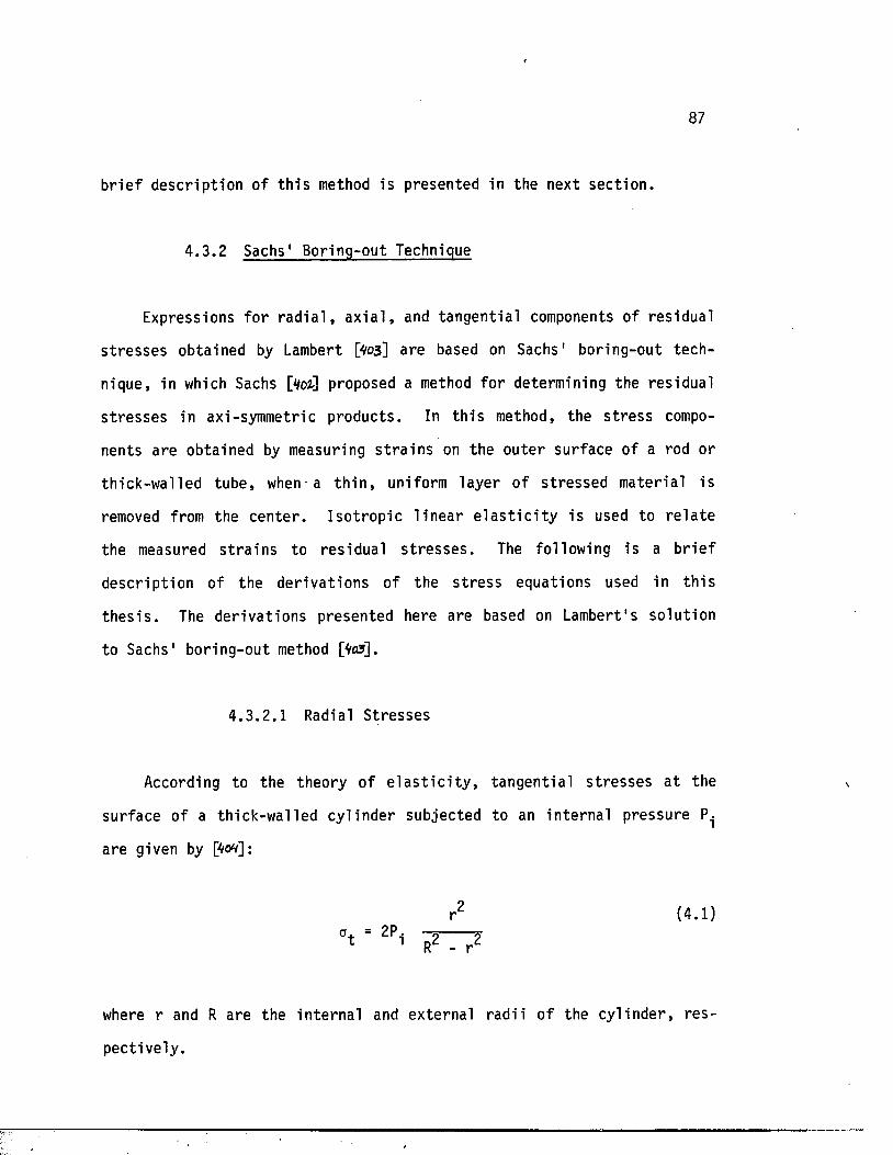
87
b r i e f desc r ip t ion of t h i s method i s presented in the next sec t ion .
4 .3 .2 Sachs' Boring-out Technique
Expressions fo r r a d i a l , a x i a l , and tangen t ia l components of res idual
s t r e s s e s obtained by Lambert [yo3] are based on Sachs' boring-out tech
nique, in which Sachs [V02] proposed a method fo r determining the res idual
s t r e s s e s in axi-symmetric products . In t h i s method, the s t r e s s compo
nents are obtained by measuring s t r a i n s on the oute r surface of a rod or
th ick-walled tube, when- a t h i n , uniform layer of s t re ssed materia l is
removed from the cen te r . I so t rop ic l in e a r e l a s t i c i t y is used to r e l a t e
the measured s t r a i n s to res idual s t r e s s e s . The following i s a b r i e f
desc r ip t ion of the de r iva t ions of the s t r e s s equations used in th i s
th e s i s . The der iva t ions presented here are based on Lambert's so lu tion
to Sachs' boring-out method [V05] .
4 .3 .2 .1 Radial S tresses
According to the theory of e l a s t i c i t y , tangen t ia l s t r e s se s a t the
surface of a th ick-walled cy l inder subjected to an in te rna l pressure
are given by pr<w]:
where r and R are the in te rna l and external rad i i o f the cy l inde r , res
pect ive ly .
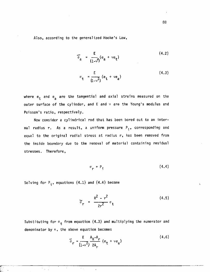
88
Also, according to the general ized Hooke's Law,
E (4 .2 )a
E (4.3)
where e. and e are the tangen t ia l and axial s t r a in s measured on thet cl
outer surface of the cy l in d e r , and E and v are the Young's modulus and
Poisson 's r a t i o , r e sp ec t iv e ly .
Now consider a c y l in d r ic a l rod t h a t has been bored out to an i n t e r
nal radius r . As a r e s u l t , a uniform pressure P.., corresponding and
equal to the o r ig ina l rad ia l s t r e s s a t radius r , has been removed from
the ins ide boundary due to the removal of materia l containing res idual
s t r e s s e s . Therefore,
Solving fo r P^, equations (4.1) and (4.4) become
Subs t i tu t ing fo r from equation (4.3) and mul tip ly ing the numerator and
denominator by ir, the above equation becomes
ar(4.5)
(4 .6 )a = --- ^ ------
r ( i - v 2; 2a,
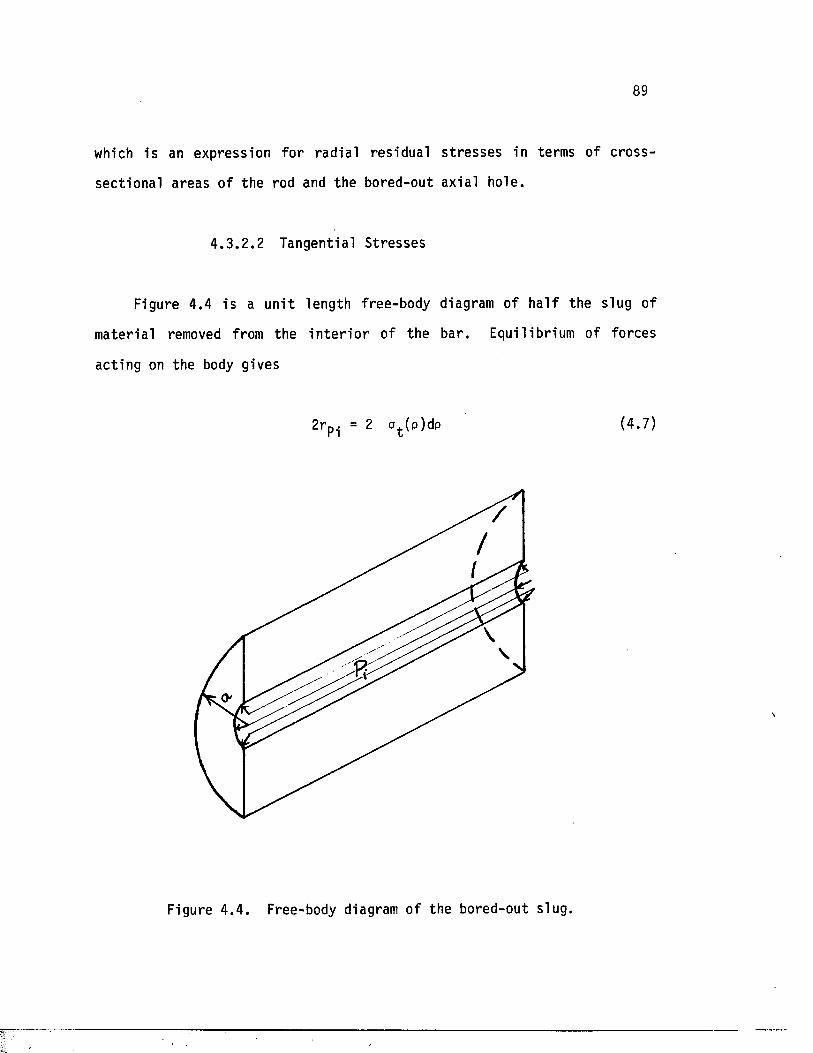
89
which i s an expression fo r rad ia l res idual s t r e s s e s in terms of c ross-
sec t iona l areas o f the rod and the bored-out axia l hole.
4 .3 .2 .2 Tangential S tresses
Figure 4.4 is a u n i t length free-body diagram of h a l f the slug of
materia l removed from the i n t e r i o r of the bar. Equilibrium of forces
acting on the body gives
2 rpi = 2 a t (p)dp (4.7)
Figure 4 .4 . Free-body diagram o f the bored-out slug.
90
S u b s t i tu t in g expressions (4 .4) and (4.5) fo r P.. and rearranging the
r e su l t in g express ion, the above equation becomes
E R2- r 2o+(p)dp = .-----5 , --------- ( e + + v e . ) ( 4 .8 )
( H 7 ) 2r ' =t '
D i f f e ren t ia t io n with respec t to r r e s u l t s in
r*
° t (r ) =(IV)
-R2- r 2 R2- r 2 de
2rT - 0 +2r dr
(4.9)
where
G = e . + ve . (4 .10 )u a
Multiplying the numerator and denominator by n and noting th a t
d0 d0 dA d0— = --------- £ = 2 i r r ------ (4.11)dr dAr dr dAr
equation (4.9) becomes
>t ( p)1 ( i V j L
de Ad + A„Ar - A ) -------------- 2------ H e | (4.12)
R r dAr 2Ar
which i s an expression fo r tangent ia l res idual s t r e s se s in terms of
c ross -sec t iona l areas of the rod and the bored-out axial hole.
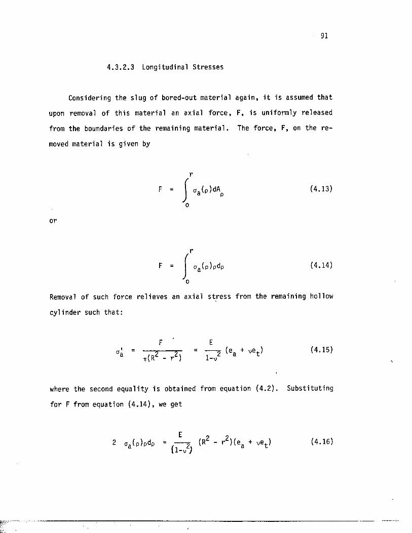
4 .3 .2 .3 Longitudinal Stresses
Considering the slug o f bored-out materia l again , i t is assumed th a t
upon removal of th i s mater ia l an axial fo rce , F, is uniformly re leased
from the boundaries of the remaining m a te r ia l . The fo rce , F, on the r e
moved materia l is given by
r
F = | oa (p)dAp (4.13)
o
or
a f l ( p ) p d p (4.14)
Removal of such force re l i ev es an axial s t r e s s from the remaining hollow
cy l inder such th a t :
EoL = — ;—5--------- 2“ = 2 ( e a + v e t ) ( 4 * 1 5 )a ttOT - r ‘ ) 1-X
where the second eq u a l i ty i s obtained from equation (4 .2 ) . Subs t i tu t ing
fo r F from equation (4 .14) , we get
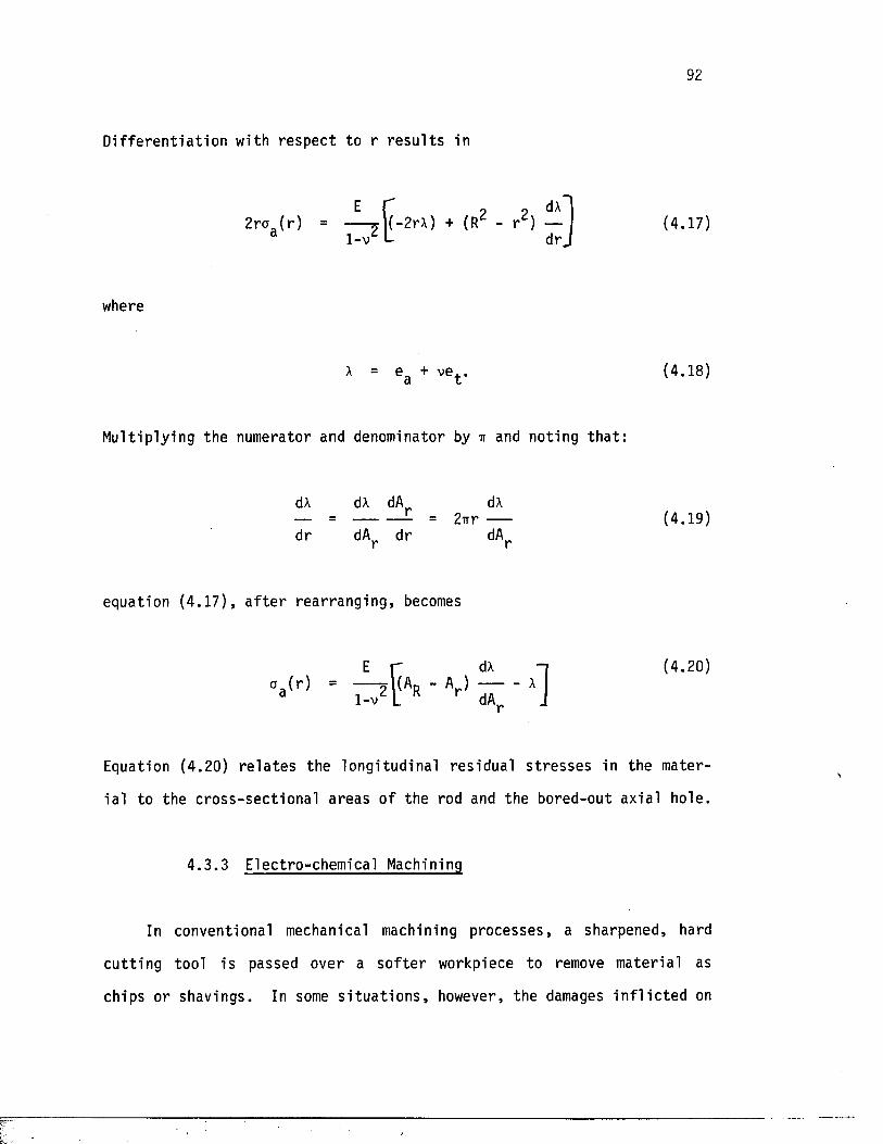
92
D if fe ren t ia t io n with respec t to r r e s u l t s in
2rag(r )-4-1-v L
2rA) + (R2 - r 2)dA
dr .(4.17)
where
A = e , + ve . .a L
(4.18)
Multiplying the numerator and denominator by it and noting th a t :
dA dA dA dA— = --------- = 2 i r r ------ (4.19)dr dA^ dr dAr
equation (4 .17) , a f t e r rearranging, becomes
E r dA -idA -] (4.20)
Equation (4.20) r e l a t e s the longitudinal res idual s t r e s s e s in the mater
ia l to the c ross -sec t iona l areas of the rod and the bored-out axial hole.
4 .3 .3 Electro-chemical Machining
In conventional mechanical machining processes, a sharpened, hard
c u t t ing tool is passed over a s o f t e r workpiece to remove materia l as
chips or shavings. In some s i t u a t i o n s , however, the damages i n f l i c t e d on
93
the mater ia l due to such machining processes are not acceptable . Thermal
damages, fo r example, could cause recovery to occur in some m a te r ia l s ,
a l t e r i n g the nature of p roper t ie s such as the res idual s t r e s s e s p/05].
Mechanical damages, on the o ther hand, are too de s t ruc t ive in s i tu a t io n s
such as sample preparation fo r microscopic observations . I t is neces
sary , th e re fo re , to remove materia l with minimum damage to the workpiece
due to the removal process i t s e l f . As a r e s u l t , a number of non-
t r a d i t i o n a l machining processes have been developed fo r s c i e n t i f i c and
commercial operat ions which take advantage o f techniques le ss harmful to
the remaining piece [Vofe]. Among these techniques , e l e c t r i c discharge
machining (EDM), chemical machining (CHM), and electro-chemical machining
(ECM) are the most widely-used mater ia l removal opera tions which use
processes o ther than shearing o f f by physical con tac t .
The opera ting p r inc ip le s of processes such as chemical and e l e c t r o
chemical machining are not newly invented but have been properly im
proved. Chemical e tch ing , for example, has been used fo r decoration and
p r in t in g purposes fo r many cen tur ies p o ? ] . More re c en t ly , since the
advent of m ic ro -e lec t ron ics , the process has been used extens ive ly to
produce pr in ted c i r c u i t boards in which the workpiece is purposely
exposed to a corrosive medium in order to corrode a l l exposed areas .
The e lectro-chemical machining process i s not new, e i t h e r . The
basis of i t s operation is the phenomenon of e l e c t r o l y s i s , the laws of
which were es tab l i shed by Faraday in 1833 [ ] . E lec t ro ly s i s i s the name
given to the chemical process which occurs when an e l e c t r i c cur ren t is
passed between two conductors dipped into a l iq u id so lu t ion . A typical
example is th a t of two copper wires connected to a source of d i r e c t cur
ren t and immersed in a so lu t ion o f copper sulphate in water, Figure 4 .5 .
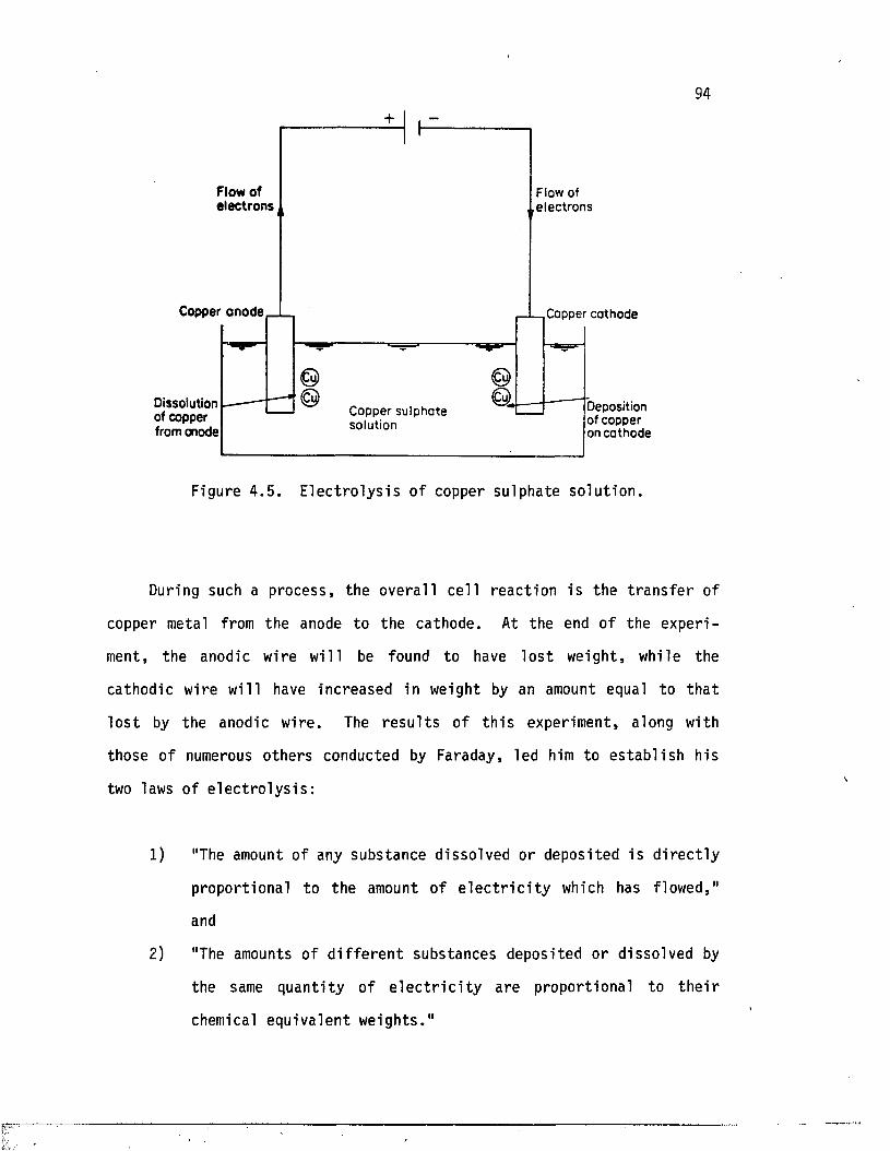
94
Flow o f e le c tro n s
Copper anode
Dissolution of copper from anode
Flow of e l e c t r o ns
Copper su l p ha t e solut ion
Copper c a t hode
Deposi t ion of copper on c a t h o d e
Figure 4 .5 . E l ec t ro ly s i s of copper sulphate so lu t ion .
During such a process , the overa ll ce l l reac t ion is the t r a n s f e r of
copper metal from the anode to the cathode. At the end of the exper i
ment, the anodic wire wil l be found to have l o s t weight, while the
cathodic wire will have increased in weight by an amount equal to th a t
l o s t by the anodic wire. The r e s u l t s of t h i s experiment, along with
those of numerous others conducted by Faraday, led him to e s t a b l i s h his
two laws of e l e c t r o l y s i s :
1) "The amount of any substance dissolved or deposited i s d i r e c t ly
propor tional to the amount of e l e c t r i c i t y which has flowed,"
and
2) "The amounts of d i f f e r e n t substances deposited or dissolved by
the same quant i ty of e l e c t r i c i t y are proport ional to t h e i r
chemical equivalent weights ."
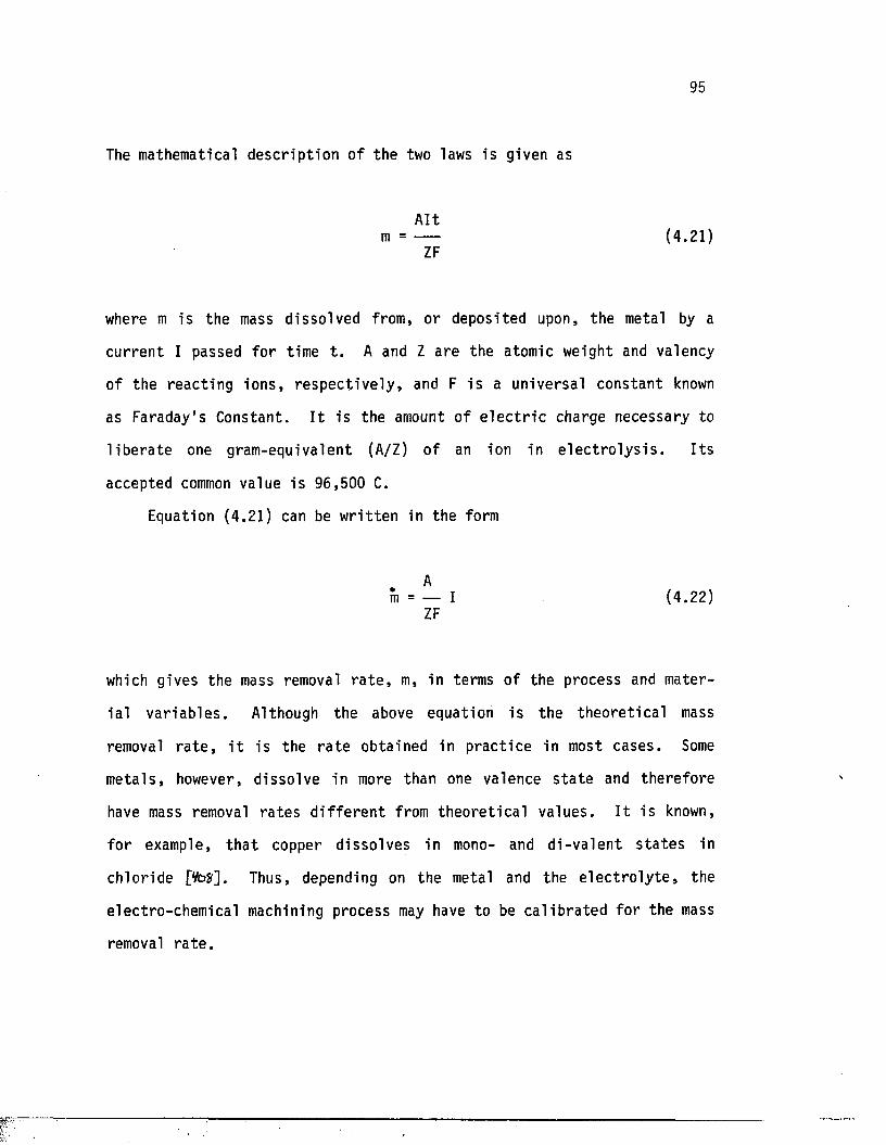
95
The mathematical d esc r ip t ion of the two laws is given as
Altm = ----- (4.21)
ZF
where m is the mass disso lved from, or deposited upon, the metal by a
cu rren t I passed fo r time t . A and Z are the atomic weight and valency
of the reac t ing ions , r e sp ec t iv e ly , and F i s a universal constant known
as Faraday's Constant. I t is the amount of e l e c t r i c charge necessary to
l i b e r a t e one gram-equivalent (A/Z) o f an ion in e l e c t r o l y s i s . I t s
accepted common value i s 96,500 C.
Equation (4.21) can be w r i t t en in the form
Am = — I (4.22)
ZF
which gives the mass removal r a t e , m, in terms of the process and mater
ia l v a r iab le s . Although the above equation i s the theo re t ic a l mass
removal r a t e , i t is the r a t e obtained in p rac t ice in most cases. Some
meta ls , however, d is so lve in more than one valence s t a t e and therefore
have mass removal ra te s d i f f e r e n t from th eo re t ic a l values . I t i s known,
fo r example, t h a t copper d is solves in mono- and d i -v a len t s t a t e s in
chloride pfctf]. Thus, depending on the metal and the e l e c t r o l y t e , the
electro-chemical machining process may have to be c a l ib ra ted fo r the mass
removal r a t e .
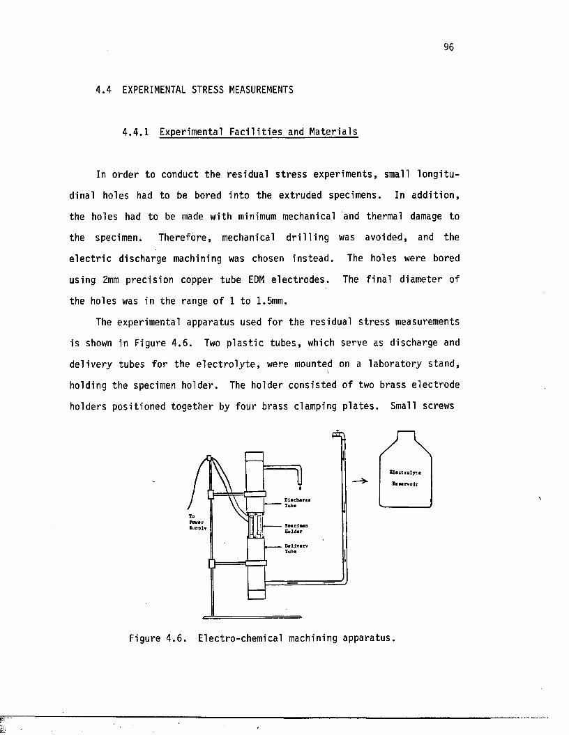
96
4.4 EXPERIMENTAL STRESS MEASUREMENTS
4.4 .1 Experimental F a c i l i t i e s and Materials
In order to conduct the res idual s t r e s s experiments, small lo n g i tu
dinal holes had to be bored in to the extruded specimens. In ad d i t ion ,
the holes had to be made with minimum mechanical and thermal damage to
the specimen. Therefore, mechanical d r i l l i n g was avoided, and the
e l e c t r i c discharge machining was chosen ins tead . The holes were bored
using 2mm prec is ion copper tube EDM e lec t ro d es . The f ina l diameter of
the holes was in the range of 1 to 1.5mm.
The experimental apparatus used fo r the re s idual s t r e s s measurements
is shown in Figure 4 .6 . Two p l a s t i c tubes , which serve as discharge and
de l ivery tubes fo r the e l e c t r o l y t e , were mounted on a labora to ry stand,-i
holding the specimen holder. The holder consis ted of two brass e lec t rode
holders posit ioned together by four brass clamping p la te s . Small screws
Figure 4 .6 . Electro-chemical machining apparatus.
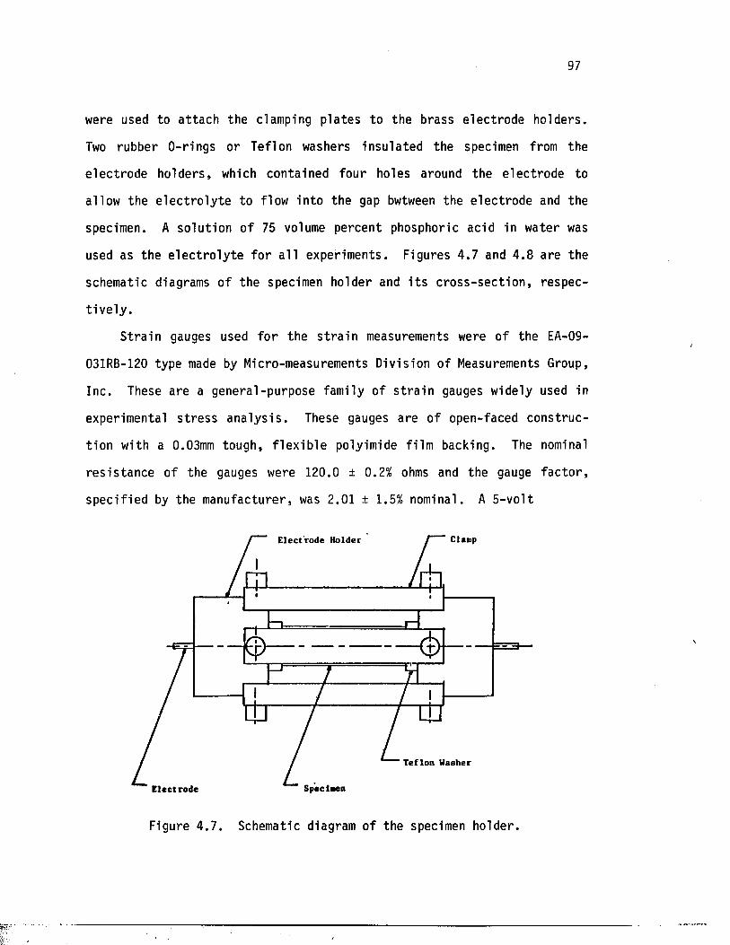
97
were used to a t tach the clamping p la te s to the brass e lec t rode holders .
Two rubber 0-r ings or Teflon washers insu la ted the specimen from the
e lec t rode holders , which contained four holes around the e lec t rode to
allow the e l e c t r o l y t e to flow in to the gap bwtween the e lec t rode and the
specimen. A so lu t ion of 75 volume percent phosphoric acid in water was
used as the e l e c t r o l y t e fo r a l l experiments. Figures 4.7 and 4 .8 are the
schematic diagrams of the specimen holder and i t s c ro s s - s e c t io n , respec
t i v e l y .
S tra in gauges used f o r the s t r a i n measurements were of the EA-09-
031RB-120 type made by Micro-measurements Division of Measurements Group,
Inc. These are a general-purpose family o f s t r a i n gauges widely used in
experimental s t r e s s a n a ly s i s . These gauges are of open-faced const ruc
tion with a 0.03mm tough, f l e x ib l e polyimide fi lm backing. The nominal
r e s i s tan ce of the gauges were 120.0 ± 0 .2% ohms and the gauge f a c to r ,
spec i f ied by the manufacturer, was 2.01 ± 1.5% nominal. A 5 -vo l t
E lec tro de Holder Clanp
(j> — £ r )
Teflon Washer
E lec trode
Figure 4 .7 . Schematic diagram o f the specimen holder.
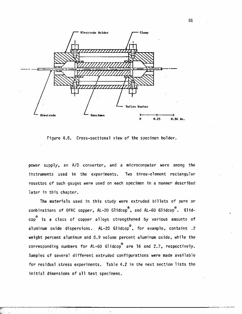
98
E lec tro de Holder Claap
7 7 7 7 7 7 7 7 7 /7 7 7 7 7 /7 -;
WZZZZZL7ZZZZZZZL
E lect rode
Teflon Washer
Soeclmen I---------- I-0 .25 0 .5 0 In .
Figure 4 .8 . Cross-sect ional view of the specimen holder.
power supply, an A/D conver te r , and a microcomputer were among the
instruments used in the experiments. Two three-e lement rec tangular
ro s e t t e s of such gauges were used on each specimen in a manner described
l a t e r in t h i s chapter.
The mater ia ls used in t h i s study were extruded b i l l e t s of pure or
combinations of OFHC copper, AL-20 Glidcop®, and AL-60 Glidcop®. Glid-
cop is a c lass of copper a l loys strengthened by various amounts of
aluminum oxide d i sper s ions . AL-20 Glidcop , fo r example, contains .2
weight percent aluminum and 0.9 volume percent aluminum oxide , while the
corresponding numbers fo r AL-60 Glidcop are 16 and 2 .7 , re spec t ive ly .
Samples of several d i f f e r e n t extruded conf igura tions were made ava i lab le
fo r residual s t r e s s experiments. Table 4.2 in the next sec t ion l i s t s the
i n i t i a l dimensions of a l l t e s t specimens.
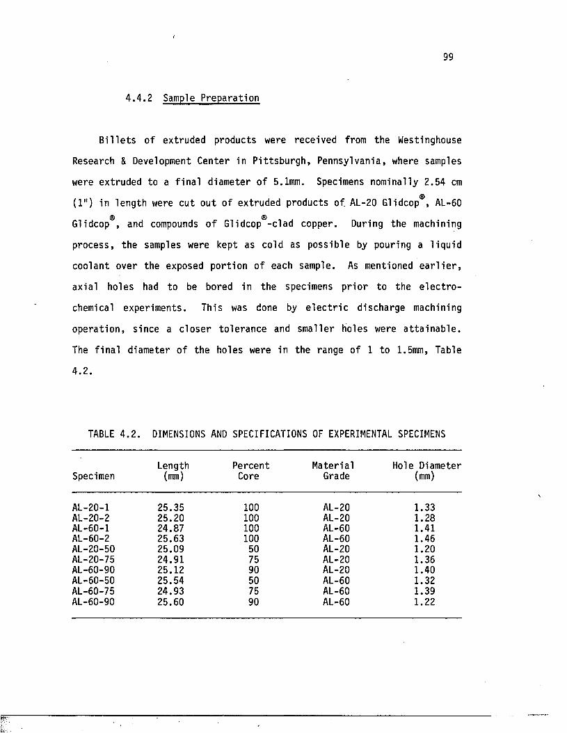
99
4 .4 .2 Sample Preparation
B i l l e t s of extruded products were received from the Westinghouse
Research & Development Center in P i t t sburgh , Pennsylvania, where samples
were extruded to a f in a l diameter of 5.1mm. Specimens nominally 2.54 cm
(1") in length were cut out of extruded products of. AL-20 Glidcop , AL-60® ®
Glidcop , and compounds o f Glidcop -c lad copper. During the machining
process , the samples were kept as cold as possible by pouring a l iqu id
coolant over the exposed portion of each sample. As mentioned e a r l i e r ,
axial holes had to be bored in the specimens p r io r to the e l e c t r o
chemical experiments. This was done by e l e c t r i c discharge machining
opera tion , since a c lo se r to le rance and smaller holes were a t t a in a b le .
The f ina l diameter of the holes were in the range of 1 to 1.5mm, Table
4.2.
TABLE 4 .2 . DIMENSIONS AND SPECIFICATIONS OF EXPERIMENTAL SPECIMENS
Length Percent Material Hole DiameterSpecimen (mm) Core Grade (mm)
AL-20-1 25.35 100 AL-20 1.33AL-20-2 25.20 100 AL-20 1.28AL-60-1 24.87 100 AL-60 1.41AL-60-2 25.63 100 AL-60 1.46AL-20-50 25.09 50 AL-20 1.20AL-20-75 24.91 75 AL-20 1.36AL-60-90 25.12 90 AL-20 1.40AL-60-50 25.54 50 AL-60 1.32AL-60-75 24.93 75 AL-60 1.39AL-60-90 25.60 90 AL-60 1.22
100
Fin a l ly , the surface of each specimen was thoroughly cleaned and
s t r a i n gauges were mounted so th a t the middle element was aligned with
the long itudinal axis o f the specimen a t t h i s s tage . The specimens were
mounted on the ECM appara tus , and the work proceeded in a manner des
cr ibed in Section 4 .4 .4 .
4 .4 .3 Cal ib ra t ion of Electro-chemical Machining
As mentioned in Section 4 .3 , although equation (4.22) could be used
to determine the r a t e of mass removal in most cases , a more accurate
r e s u l t i s obtained through actual experiments in which a known curren t is
passed through the c e l l f o r d i f f e r e n t lengths of time and the mass
removed a f t e r each run i s measured. This was accomplished by using the
experimental set -up shown in Figure 4 .3 , with the specimen as anode and
the clamping p la te s as cathode.
A so lu t ion of 75 volume percent phosphoric acid in water was used as
e l e c t r o l y t e and the c a l i b r a t i o n experiment was conducted fo r a l l three
m a te r ia l s , namely copper Glidcop-60®, and Glidcop-20®. The mass removed
a f t e r each run then was determined and l i n e r equations were obtained;
these r e l a t e the mass removed, m in mg, to t ime, t in minutes, fo r each
m a te r ia l . The equation fo r copper, a t a cu r ren t o f 0.6 amp, is
m = 18.4332t + 1.1325. (4.23)
For Glidcop-20®, a t the same cu r ren t , the equation was found to be
m = 17.6382t + 1.2410, (4 .24 )
101
and fo r Glidcop-60 , the equation is
m = 15.3116t + 0.9812. (4.25)
4 .4 .4 Experimental Procedure
AL-20 Glidcop , AL-60 Glidcop , and copper-clad Glidcop core
specimens were prepared as explained in Section 4 .4 .2 and were mounted in
the elec tro-chemical machining apparatus shown in Figure 4 .3 . A p re c i
sion copper rod was used as cathode and was inser ted in the axial hole
through the brass e lec t rode holders . Each gauge was made the ac t ive leg
of a s t r a i n gauge bridge. After c a l i b r a t i n g the bridges , a cur ren t of
0.6 amp was passed through the elec tro-chemical c e l l , which was made up
of the specimen, the e l e c t r o l y t e , and the cathodic copper tube. The
bridge input was 5 VDC and the amplified voltage change across the bridge
was converted to d i g i t a l s igna l s by the A/D conver te r and recorded by the
microcomputer every four minutes.
After each successful experiment, the q u a n t i t i e s 0 and A of equa
tions (4.10) and (4.18) were determined, and the mass removal r a te was
converted to area removal r a t e using the equation
m = pv = pAL. (4.26)
After f inding A and 6 in terms of the area removed, the data were
smoothed using the le as t - sq u a re curve f i t t i n g technique, and the slopes
de/dA and dA/dA were determined. Equations (4 .6 ) , (4 .12 ) , and (4.20)
102
then were used to determine the r a d i a l , t a n g e n t i a l , and rad ia l s t r e s s e s ,
re spec t ive ly . These r e s u l t s , along with the f i n i t e element r e s u l t s , are
presented in the next chapte r . Conclusive remarks with regard to the
comparison of the experimental and numerical r e s u l t s are made in Chapter
6 .
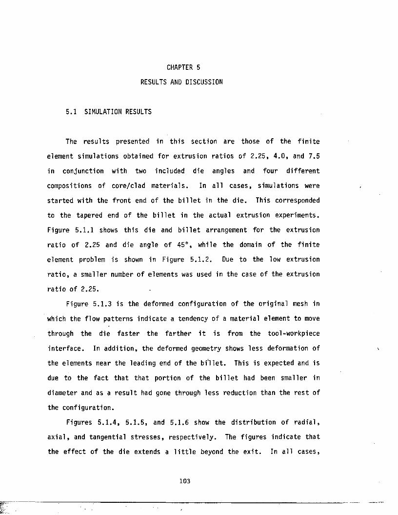
CHAPTER 5
RESULTS AND DISCUSSION
5.1 SIMULATION RESULTS
The r e s u l t s presented in t h i s sec tion are those of the f i n i t e
element simula tions obtained fo r extrusion r a t i o s o f 2.25, 4 .0 , and 7.5
in conjunction with two included die angles and four d i f f e r e n t
compositions of core /c lad m a te r ia l s . In a l l cases , simulations were
s t a r t e d with the f ro n t end of the b i l l e t in the d ie . This corresponded
to the tapered end of the b i l l e t in the actual ext rusion experiments.
Figure 5 .1 .1 shows th i s die and b i l l e t arrangement fo r the extrusion
r a t i o of 2.25 and die angle of 45°, while the domain of the f i n i t e
element problem is shown in Figure 5 .1 .2 . Due to the low extrusion
r a t i o , a smaller number of elements was used in the case o f the extrusion
r a t i o o f 2.25.
Figure 5.1 .3 i s the deformed conf igura tion of the o r ig ina l mesh in
which the flow pa t te rns ind ica te a tendency of a mater ia l element to move
through the die f a s t e r the f a r th e r i t i s from the tool-workpiece
in te r f a c e . In ad d i t ion , the deformed geometry shows le ss deformation of
the elements near the leading end of the b i ' l l e t . This is expected and is
due to the f a c t t h a t t h a t port ion of the b i l l e t had been smal ler in
diameter and as a r e s u l t had gone through less reduction than the r e s t of
the conf igura t ion .
Figures 5 .1 .4 , 5 .1 .5 , and 5 .1 .6 show the d i s t r i b u t io n o f r a d i a l ,
a x i a l , and tangen t ia l s t r e s s e s , re spec t ive ly . The f igures ind ica te tha t
the e f f e c t of the die extends a l i t t l e beyond the e x i t . In a l l cases,
103
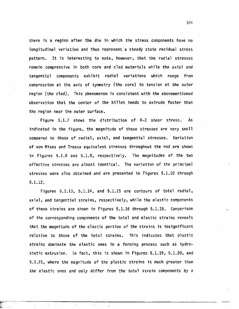
104
there is a region a f t e r the die in which the s t r e s s components have no
longitudinal v a r ia t ion and thus represen t a steady s t a t e res idual s t r e s s
p a t t e rn . I t i s i n t e r e s t i n g to note , however, t h a t the rad ia l s t r e s s e s
remain compressive in both core and clad m ate r ia ls while the axial and
tangen t ia l components ex h ib i t rad ia l v a r ia t io n s which range from
compression a t the axis of symmetry (the core) to tension a t the outer
region (the c lad ) . This phenomenon is cons i s ten t with the abovementioned
observation t h a t the cen te r o f the b i l l e t tends to extrude f a s t e r than
the region near the oute r su r face .
Figure 5 .1 .7 shows the d i s t r i b u t io n of R-Z shear s t r e s s . As
indicated in the f ig u r e , the magnitude of these s t r e s s e s are very small
compared to those of r a d i a l , a x i a l , and tangen t ia l s t r e s s e s . Variation
of von Mises and Tresca equivalent s t r e s s e s throughout the rod are shown
in Figures 5 .1 .8 and 5 .1 .9 , re spec t ive ly . The magnitudes of the two
e f f e c t iv e s t r e s s e s are almost i d e n t i c a l . The va r ia t io n of the pr incipal
s t r e s s e s were a lso obtained and are presented in Figures 5.1.10 through
5.1.12.
Figures 5 .1 .13 , 5 .1 .14 , and 5.1.15 are contours of to t a l r a d i a l ,
a x i a l , and tangen t ia l s t r a i n s , r e sp ec t iv e ly , while the e l a s t i c components
of these s t r a i n s are shown in Figures 5.1.16 through 5 .1 .18. Comparison
of the corresponding components o f the t o t a l and e l a s t i c s t r a in s reveals
t h a t the magnitude of the e l a s t i c por tion of the s t r a i n s i s i n s ig n i f i c a n t
r e l a t i v e to those of the to t a l s t r a i n s . This ind ica tes t h a t p l a s t i c
s t r a in s dominate the e l a s t i c ones in a forming process such as hydro
s t a t i c ex t rus ion . In f a c t , t h i s is shown in Figures 5 .1 .19 , 5 .1 .20 , and
5.1 .21, where the magnitude o f the p l a s t i c s t r a in s i s much g rea te r than
the e l a s t i c ones and only d i f f e r from the to t a l s t r a i n components by a
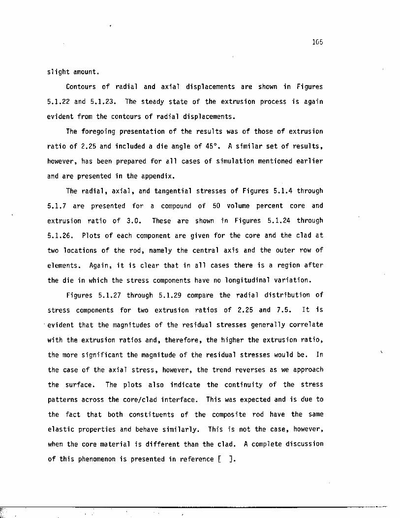
f
105
s l i g h t amount.
Contours of rad ia l and axia l displacements are shown in Figures
5.1.22 and 5 .1 .23. The steady s t a t e of the ex trus ion process i s again
evident from the contours of rad ia l displacements.
The foregoing presen ta t ion of the r e s u l t s was o f those of extrusion
r a t i o of 2.25 and included a die angle o f 45°. A s im i la r s e t o f r e s u l t s ,
however, has been prepared fo r a l l cases of simulation mentioned e a r l i e r
and are presented in the appendix.
The r a d i a l , a x i a l , and tangen t ia l s t r e s s e s of Figures 5 .1 .4 through
5 .1 .7 are presented fo r a compound of 50 volume percent core and
extrusion r a t i o o f 3 .0 . These are shown in Figures 5 .1 .24 through
5 .1 .26. Plots of each component are given fo r the core and the clad a t
two locat ions o f the rod, namely the centra l axis and the oute r row of
elements. Again, i t is c l e a r t h a t in a l l cases there i s a region a f t e r
the die in which the s t r e s s components have no longitudinal v a r i a t io n .
Figures 5.1.27 through 5.1.29 compare the rad ia l d i s t r i b u t i o n of
s t r e s s components fo r two extrusion r a t i o s of 2.25 and 7 .5 . I t is
evident th a t the magnitudes o f the res idual s t r e s s e s genera l ly c o r r e la t e
with the extrus ion r a t io s and, th e re fo re , the higher the ex trus ion r a t i o ,
the more s ig n i f i c a n t the magnitude of the res idual s t r e s s e s would be. In
the case of the axial s t r e s s , however, the trend reverses as we approach
the surface . The p lo ts a lso ind ica te the con t inu i ty of the s t r e s s
pa t te rns across the core /c lad in te r f a c e . This was expected and is due to
the f a c t t h a t both cons t i tuen ts of the composite rod have the same
e l a s t i c proper t ies and behave s im i la r ly . This is not the case, however,
when the core mater ia l is d i f f e r e n t than the c lad. A complete d iscussion
of t h i s phenomenon is presented in reference [ ] .
Figure 5.1 .1 Die and b i l l e t conf igura t ion . (<*= 22.5° R = 2.25 % core = 100)
Figure 5 .1 .2 Domain of the f i n i t e element formulation. ( a = 22.5° R = 2.25 % core = 100)
7 Z
Figure 5 .1 .3 Deformed conf igura t ion . (0t= 22.5° R = 2.25 % core = 100)
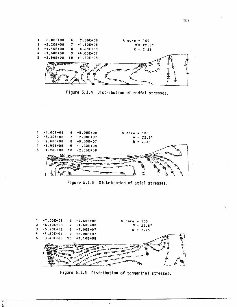
12345
123H5
123h5
107
- 6 . 0 0 E + 0 8 6 - 2 . 0 0 E + 0 8- 5 . 2 0 E + 0 8 7 -1 . 2 0 E + 0 8
. 4 0 E + 0 8 8 - 4 . 0 0 E + 0 8- 3 . 6 0 E + 0 8 9 + 4 . 0 0 E + 0 7- 2 . 8 0 E + 0 8 10 + 1 . 2 0 E + 08
% c o r e
R = 2 . 2 5
m LU 0 0 £ u UJ
Figure 5 .1 .4 D is t r ibu t ion o f rad ia l s t r e s s e s ,
- 4 . 0 0 E + 0 8 6 - 5 . 0 0 E + 0 8- 3 . 3 0 E + 0 8 7 + 2 . 0 0 E + 0 7- 2 . 6 0 E + 0 8 8 + 9 . 0 0 E + 0 7- 1 . 90E+OB 9 + 1 . 6 0 E + 0 8- 1 . 2 0 E + 0 8 1 0 + 2 . 3 0 E + 0 8
% c o r e2 2 . 5
CDEDTDTD
r ^ Ul ^ ---^
Figure 5 .1 .5 D is t r ibu t ion of ax ia l s t r e s s e s ,
■ 7 . 0 0 E + 0 8 ■ 6 . 1 0 E + 0 8 ■ 5 . 2 0 E + 0 8 • k . 3 0 E + 0 8 • 3 . 4 0 E + 0 8
- 2 . 5 0 E + 0 8 -1 . 6 0 E + 0 8 - 7 . 0 0 E + 0 7 +2 . 0 0 E + 0 7 + 1 . 1 0 E + 0 8
% c o r e = 100 a = 2 2 . 5 ' R = 2 . 2 5
Figure 5 .1 .6 D is t r ibu t ion of tangen t ia l s t r e s s e s .
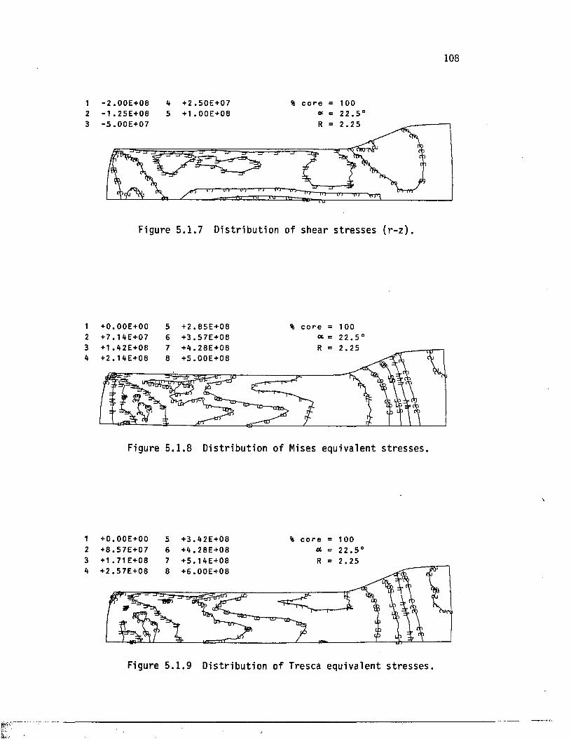
123
1234
1234
108
■ 2 . 0 0 E + 0 8 ■1 . 2 5 E + 0 8
+ 2 . 5 0 E + 07 + 1 . 0 0 E + 0 8
% c o r e = 100« = 2 2 . 5 *
5 . 0 0 E + 0 7
-PT-PT
Figure 5 .1 .7 D is t r ib u t io n o f shear s t r e s s e s ( r - z ) .
+ 0 . 0 0 E + 0 0 + 7 . 1 4 E + 0 7
56
+ 2 . 8 5 E + 0 8+ 3 . 5 7 E + 0 8
% c o r e = 100oc = 2 2 . 5 ‘
+ 1 . 4 2 E + 0 8 + 2 . 1 4 E + 0 8
2 . 2 5
Figure 5 .1 .8 D is t r ibu t ion of Mises equivalent s t r e s s e s .
+ 0 . 0 0 E + 0 0 + 8 . 5 7 E + 0 7 + 1 . 7 1 E +08
+ 3 . 4 2 E + 0 8+ 4 . 2 8 E + 0 8+ 5 . 1 4 E + 0 8
% c o r e = 100 * = 2 2 . 5 ' R = 2 . 2 5
+ 2 . 5 7 E + 0 8 + 6 . 0 0 E + 0 8
Figure 5 .1 .9 D is t r ibu t ion of Tresca equivalent s t r e s s e s .
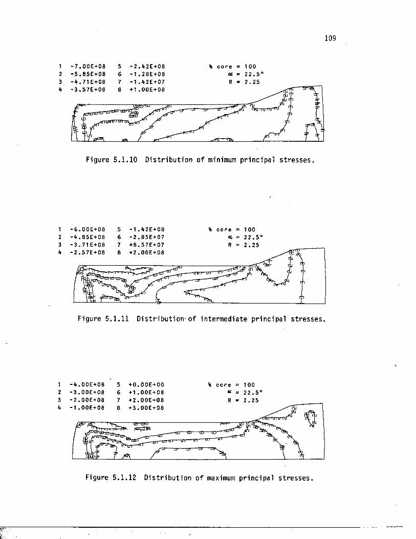
1234
1234
1234
109
- 7 . 0 0 E + 0 8 ■ 5 . 8 5 E + 0 8 ■ 4 . 7 1 E+08
5 - 2 . 4 2 E + 0 86 - 1 . 2 8 E + 0 87 - 1 . 4 2 E + 0 7
% c o r e Oi
R
1 0 0
2 2 . 5 '2 . 2 5
- 3 . 5 7 E + 0 8 + 1 . OOE+08
c 3
t 3
Figure 5 .1 .10 D is t r ibu t ion of minimum pr inc ipa l s t r e s s e s .
- 6 . 0 0 E + 0 8 - 4 . 8 5 E + 0 8 ■ 3 . 7 1 E+08
56 7
- 1 . 4 2 E + 0 8 - 2 . 8 5 E + 0 7 + 8 . 5 7 E + 0 7
% c o r e = 100X = 2 2 . 5 ' R = 2 . 2 5
- 2 . 5 7 E + 0 8 + 2 . OOE+08
|iS'*-rrfT”'3fc:n
Figure 5.1.11 D is t r ib u t io n - o f inte rmediate p r inc ipa l s t r e s s e s .
- 4 . 0 0 E + 0 8 - 3 . 0 0 E + 08 - 2 . 0 0 E + 0 8 - 1 . 0 0 E + 0 8
5 + 0 . 0 0 E + 0 06 + 1 . 0 0 E + 0 87 + 2 . OOE+088 + 3 . 0 0 E + 0 8
% c o r e = 100 at = 2 2 . 5 ' R = 2 . 2 5
tE=a5D
Figure 5.1 .12 D is t r ibu t ion o f maximum pr inc ipa l s t r e s s e s .
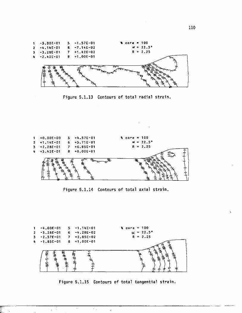
1234
1234
1234
110
■ 5 . 0 0 E - 0 1■ 4 . 1 4 E - 0 1■ 3 . 2 8 E - 0 1
56 7
- 1 . 5 7 E - 0 1 - 7 . 1 4 E - 0 2 + 1 . 4 2 E - 0 2
% c o r e * 100erf = 2 2 . 5 ‘ R = 2 . 2 5
+ 1 . 0 0 E - 0 1
ft 3
( .3
Figure 5 .1 .13 Contours of t o t a l rad ia l s t r a i n .
+ 0 . 0 0 E - 0 0 + 1 . 1 4 E - 0 1
+ 4 . 5 7 E - 0 1+ 5 . 7 1 E - 0 1
% c o r e = 100«* = 2 2 . 5 '
2 . 2 5+ 6 . 8 5 E - 0 1+ 8 . 0 0 E - 0 1
Figure 5 .1 .14 Contours o f to t a l axial s t r a i n .
- 4 . 0 0 E - 0 1- 3 . 2 8 E - 0 1- 2 . 5 7 E - 0 1
- 1 . 1 4 E - 0 1 - 4 . 2 8 E - 0 2 + 2 . 8 5 E - 0 2
% c o r e = 100C*. = 2 2 . 5 ' R = 2 . 2 5
+ 1 . 0 0 E - 0 11 . 8 5 E - 0 1
o
Figure 5 .1 .15 Contours o f to ta l tangentia l s t ra in .
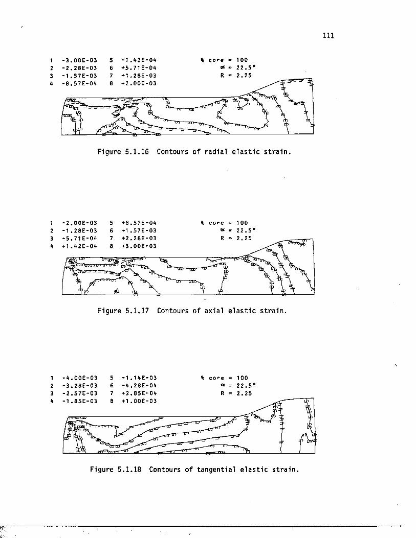
I l l
1 - 3 . 0 0 E - 0 3 5 - 1 . 4 2 E - 0 4 % c o r e = 1 0 02 - 2 . 2 8 E - 0 3 6 + 5 . 7 1 E - 0 4 <* = 2 2 . 5 °
+ 1 . 2 8 E - 0 3 + 2 . 0 0 E - 0 3
T 3 ------
T tT
Figure 5.1.16 Contours of rad ia l e l a s t i c s t r a i n .
- 2 . 0 0 E - 0 3 -1 . 2 8 E - 0 3
+ 8 . 5 7 E - 0 4 + 1 . 5 7 E - 0 3
% c o r e = 1 0 0 « = 2 2 . 5 ‘
+ 2 . 2 8 E - 0 3+ 3 . 0 0 E - 0 3
2 . 2 53 - 5 . 7 1 E - 0 44 + 1 . 4 2 E - 0 4
HUT
1UU MET
Figure 5.1.17 Contours of ax ia l e l a s t i c s t r a i n .
- 4 . 0 0 E - 0 3- 3 . 2 8 E - 0 3- 2 . 5 7 E - 0 3
- 1 . 1 4 E - 0 3 - 4 . 2 8 E - 0 4 + 2 . 8 5 E - 0 4
c o r e = 1 0 0 « = 2 2 . 5 * R = 2 . 2 5
1 . 8 5 E - 0 3
Figure 5 .1 .1 8 Contours o f tangentia l e la s t ic s t ra in .
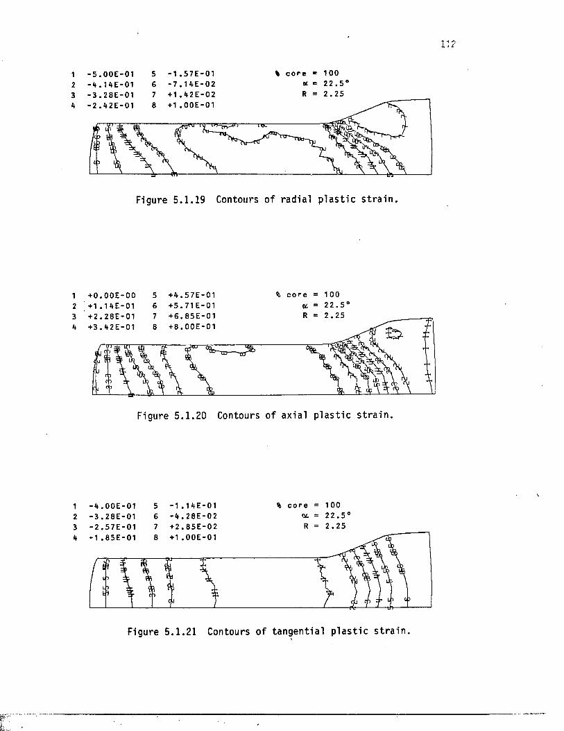
i i 2
1 - 5 . 0 0 E - 0 1 5 - 1 . 5 7 E - 0 1 % c o r e * 1 0 02 - 4 . 1 4 E - 0 1 G - 7 . 1 4 E - 0 2 <* = 2 2 . 5 °3 - 3 . 2 8 E - 0 1 7 + 1 . 4 2 E - 0 2 R = 2 . 2 5
+ 1 . 0 0 E - 0 12 . 4 2 E - 0 1
13
Figure 5 .1.19 Contours of rad ia l p l a s t i c s t r a i n .
+ 0 . 0 0 E - 0 0 + 1 . 1 4 E - 0 1
+ 4 . 5 7 E - 0 1 + 5 . 7 1 E -0 1
c o r e = 1 0 0 Oi = 2 2 . 5 '
2 . 2 5+ 6 . 8 5 E - 0 1+ 8 . 0 0 E - 0 1
3 + 2 . 2 8 E - 0 14 + 3 . 4 2 E - 0 1
0)
Figure 5 .1 .20 Contours of axia l p l a s t i c s t r a i n .
- 4 . 0 0 E - 0 1- 3 . 2 8 E - 0 1- 2 . 5 7 E - 0 1
- 1 . 1 4 E - 0 1 - 4 . 2 8 E - 0 2 + 2 . 8 5 E - 0 2
% c o r e = 1 00 ot = 2 2 . 5 ' R = 2 . 2 5
8 + 1 . 0 0 E - 0 11 . 8 5 E - 0 1
15
Figure 5 .1 .21 Contours o f tangentia l p la s t ic s t ra in .
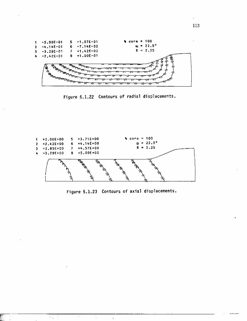
113
1 - 5 . 0 0 E - 0 1 5 - 1 . 5 7 E - 0 1 * c o r e « 1 0 02 - 4 . 1 4 E - 0 1 6 - 7 . 1 E - 02 OL - 2 2 . 5 °
2 . 2 5+ 1 . 4 2 E - 0 2 + 1 . 0 0 E - 0 14
■nr TO-m-
TTTTT TTT TTT ■or
‘tD ® CD- t o -TD" xcr to- to-
Figure 5 .1 .22 Contours of rad ia l displacements.
+ 2 . 0 0 E + 0 0 + 2 . 4 2 E+ 00
56
+ 3 . 7 1 E +0 0 + 4 . 1 4 E + 0 0
% c o r e = 100C* = 2 2 . 5 '
2 . 2 53 + 2 . 8 5 E + 0 04 + 3 . 2 8 E + 0 0
Figure 5 .1 .23 Contours o f axial displacements.
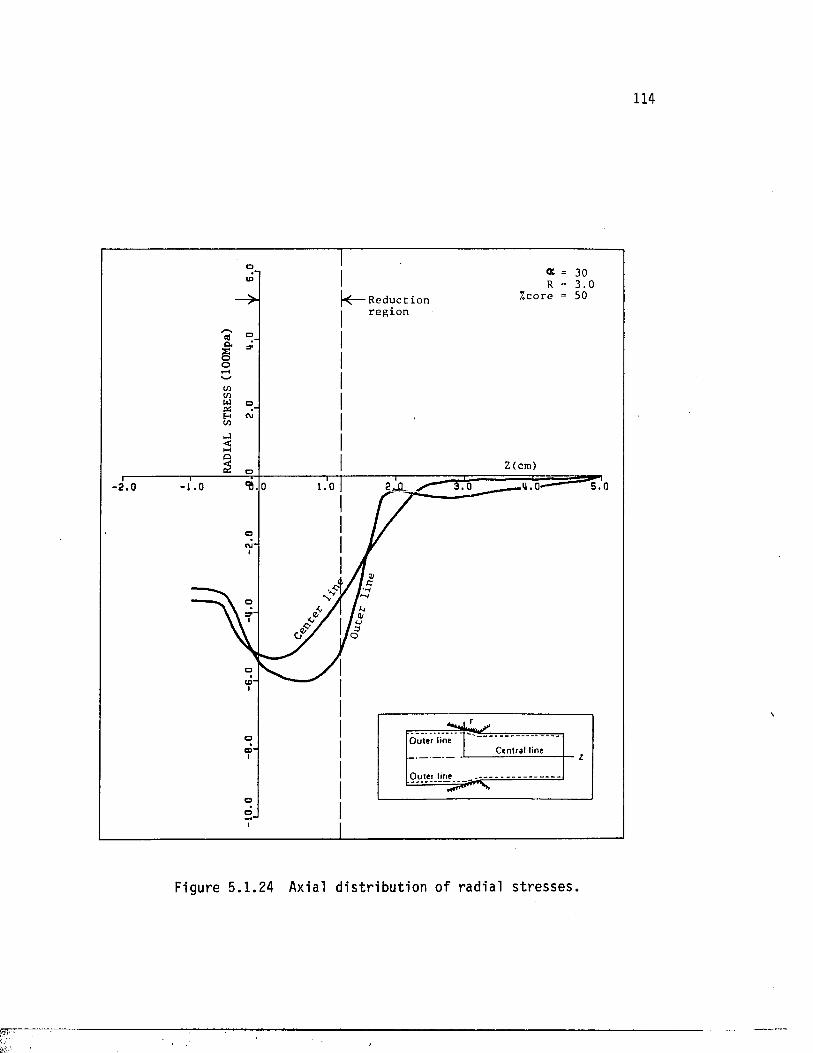
114
R e d u c t io nr e g i o n
o
2 (cm)
- 2 . 0
oC\J'
o
<D“
Outer tineCentral lineCD'
Outer line
o
Figure 5 .1 .24 Axial d is t r ib u t io n o f rad ia l stresses.
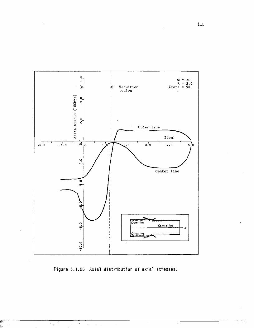
115
h - R e d u c t io n I r e g io n
%core
o
O u te r l i n e
Z(cm)- 2 . 0
C e n t e r l i n e
Outer lineCentral line
Outer line
Figure 5 .1 .25 Axial d is t r ib u t io n o f ax ia l stresses.
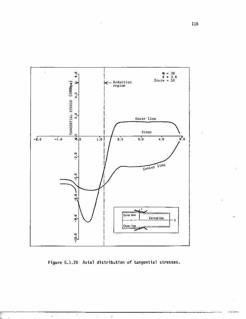
116
1^— R e d u c t io n r e g io n
co
O u te r l i n e
Z(cm)
- 2 . 0
—— l i n eC e n te t
o
Outer lineCentral lineCD“
Outer line
Figure 5 .1 .2 6 Axial d is t r ib u t io n o f tangentia l stresses.
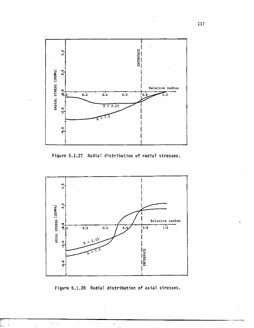
m
R e l a t i v e r a d iu s
0 . 2
2 . 2 5
a
Figure 5.1.27 Radial d i s t r i b u t io n o f rad ia l s t r e s s e s .
R e la t i v e r a d iu s
Q. 2
o
Figure 5 .1 .2 8 Radial d is tr ib u t io n of a x ia l stresses.
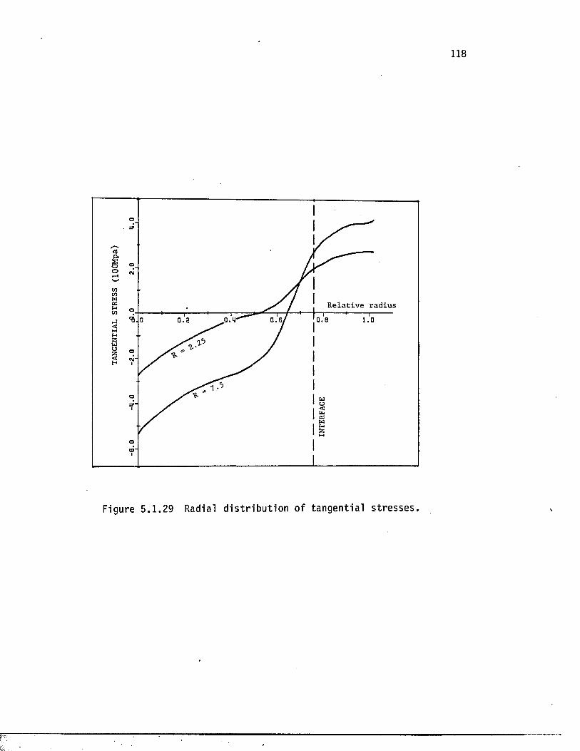
o
R e la t iv e r a d iu s
Figure 5.1.29 Radial d i s t r i b u t io n of tangen t ia l s t r e s s e s .
119
In the simulation of the ex trus ion problem, the f lu i d pressure of
the actual press was simulated as pressure boundary conditions on the
back end and top of the b i l l e t s . As the extrusion proceeded, the
simulation process was stopped in due time to remove the load from th a t
por tion of the rod which had entered the d ie . In continuing the process,
the cycle was repeated u n t i l the steady s t a t e was acquired. This
condit ion is evident from Figure 5 .1 .30 , in which the va r ia t ion of the
load f a c to r i s p lo t ted aga ins t the displacement of the back end of the
b i l l e t . Load f a c to r i s a c o e f f i c i e n t t h a t the program uses as a
m u l t ip l i e r of the assigned load. Afte r a peak in the load value, the
breakthrough pressure , the magnitude o f the pressure remains e s s e n t i a l l y
constant. Small v a r ia t io n of the pressure i s due to the minor lag in
pressure compensation. As the b i l l e t moves forward, the volume of the
chamber inc reases ; as a r e s u l t , the pressure drops only fo r the pump to
compensate for the d e f i c i t amount.
Table 5.1 gives the numerical values of the breakthrough and steady-
s t a t e pressure fo r a l l cases. The breakthrough pressure is general ly
higher than the steady s t a t e value and corresponds to the peak value of
the load shown in Figure 5 .1 .30.
Figures 5.1.31 and 5.1.32 show the va r ia t ions of extrusion pressure
with ext rusion r a t i o . For a l l four b i l l e t conf igura t ions , the r e la t io n
between the steady s t a t e pressure and the natura l logarithm of the
ext rusion is l i n e a r , which i s cons is ten t with the empirical equations
presented in Chapter 2.
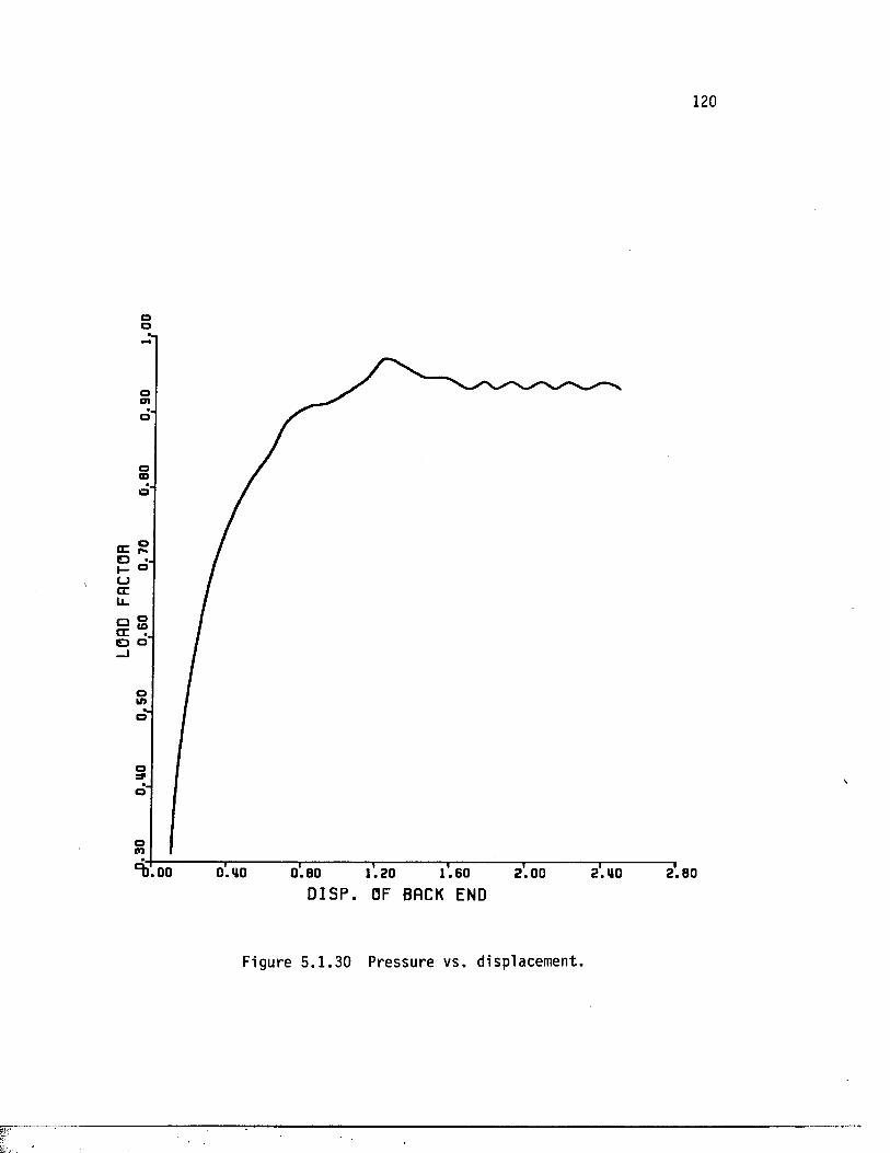
120
oo
O)
CD
JH— wCC r- OCJcrLl_
ino
n
0.8000 0 .U0 1.20D I S P . OF BACK END
1.60 2 .0 0 2.80
Figure 5 .1 .3 0 Pressure vs. displacement.
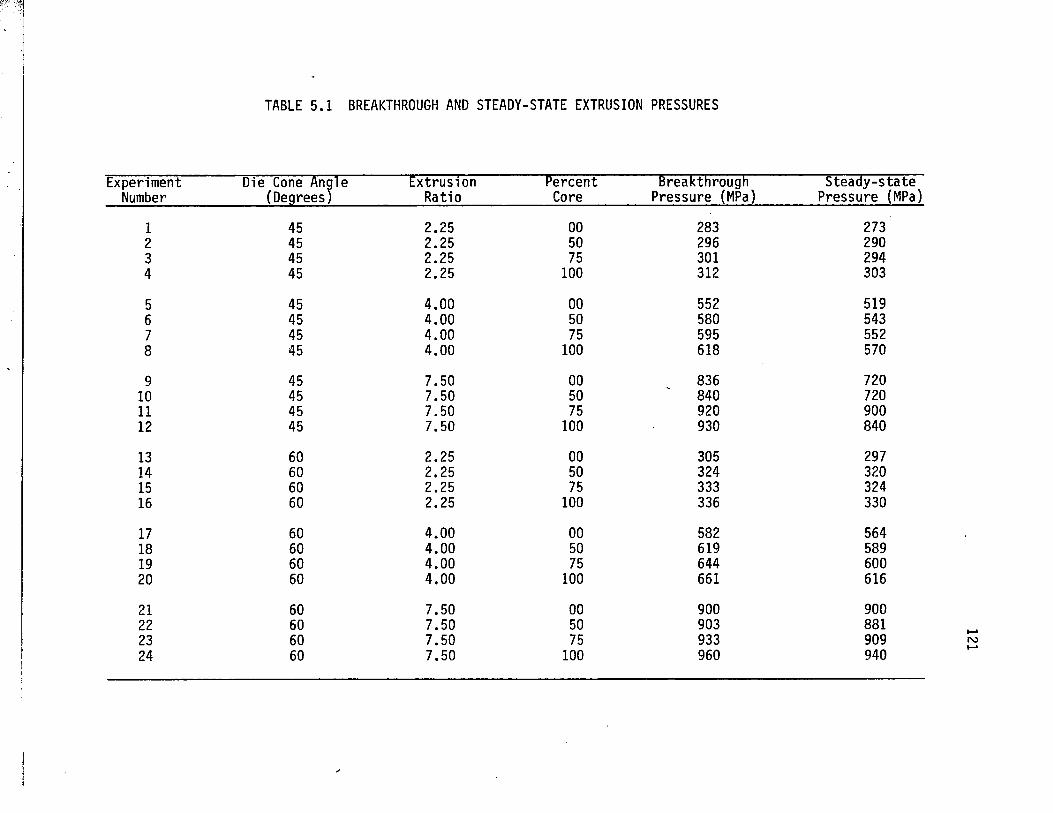
TABLE 5.1 BREAKTHROUGH AND STEADY-STATE EXTRUSION PRESSURES
ExperimentNumber
Die Cone Angle (Degrees)
ExtrusionRatio
PercentCore
Breakthrough Pressure (MPa)
Steady-s ta te Pressure (MPa)
1 45 2.25 00 283 2732 45 2.25 50 296 2903 45 2.25 75 301 2944 45 2.25 100 312 303
5 45 4.00 00 552 5196 45 4.00 50 580 5437 45 4.00 75 595 5528 45 4.00 100 618 570
9 45 7.50 00 836 72010 45 7.50 50 840 72011 45 7.50 75 920 90012 45 7.50 100 930 840
13 60 2.25 00 305 29714 60 2.25 50 324 32015 60 2.25 75 333 32416 60 2.25 100 336 330
17 60 4.00 00 582 56418 60 4.00 50 619 58919 60 4.00 75 644 60020 60 4.00 100 661 616
21 60 7.50 00 900 90022 60 7.50 50 903 88123 60 7.50 75 933 90924 60 7.50 100 960 940
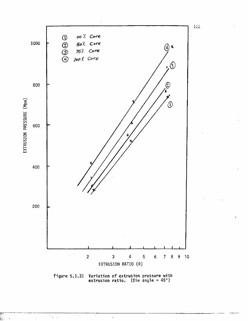
EXTR
USIO
N PR
ESSU
RE
(Mpa
)
1000
800
600
400
200
2 3 4 5 6 7 8 9 10
EXTRUSION RATIO (R)
Figure 5 .1 .31 Var ia tion o f extrusion pressure withextrusion r a t io . (Die angle = 45°)
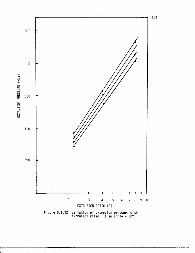
EXTR
USIO
N PR
ESSU
RE
(Mpa
)
1000
800
600
400
200
2 3 4 5 6 7 8 9 10EXTRUSION RATIO (R)
Figure 5 .1 .32 V aria t io n o f extrusion pressure withextrusion r a t io . (Die angle = 60°)
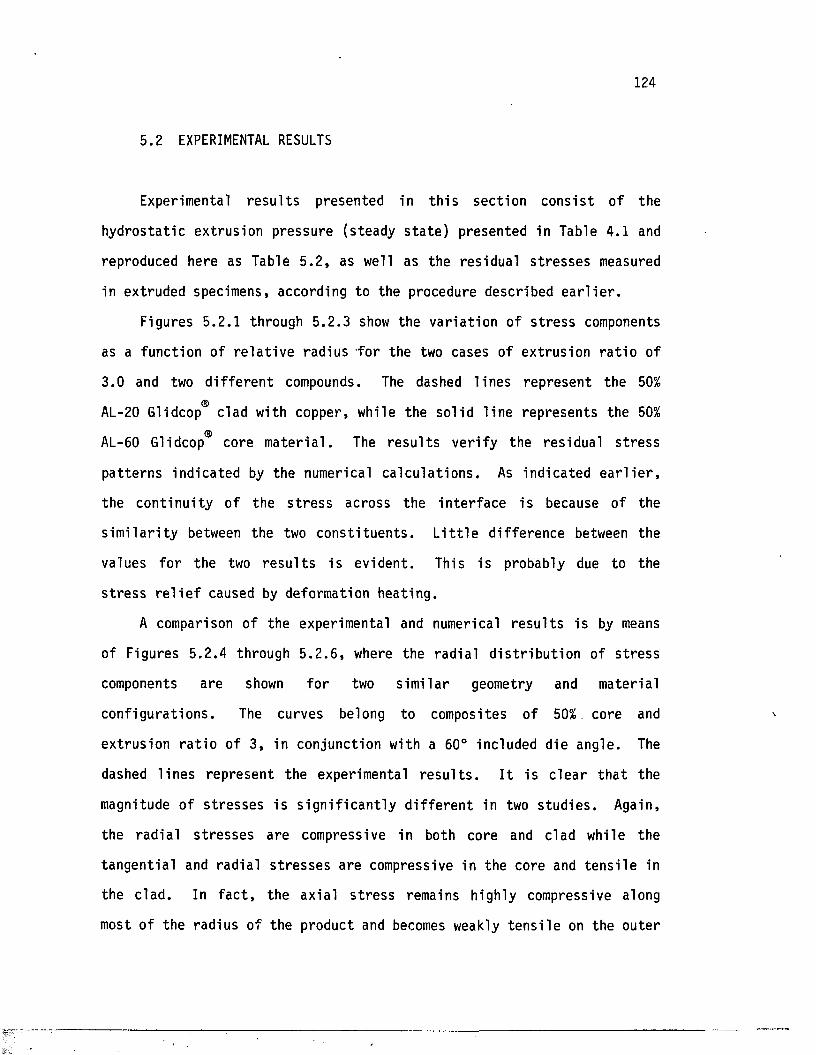
124
5.2 EXPERIMENTAL RESULTS
Experimental r e s u l t s presented in t h i s sec t ion co n s i s t o f the
hydros ta t ic ex trus ion pressure (steady s t a t e ) presented in Table 4.1 and
reproduced here as Table 5 .2 , as well as the res idual s t r e s s e s measured
in extruded specimens, according to the procedure described e a r l i e r .
Figures 5.2 .1 through 5 .2 .3 show the va r ia t ion of s t r e s s components
as a function of r e l a t i v e radius for the two cases of extrusion r a t i o of
3.0 and two d i f f e r e n t compounds. The dashed l ines represent the 50%
AL-20 Glidcop clad with copper, while the so l id l ine represents the 50%<5>AL-60 Glidcop core m a te r ia l . The r e s u l t s ve r i fy the res idual s t r e s s
pa t te rns indica ted by the numerical c a lc u la t io n s . As indica ted e a r l i e r ,
the con t inu i ty of the s t r e s s across the in te r face i s because of the
s i m i l a r i t y between the two c o n s t i tu en ts . L i t t l e d i f ference between the
values fo r the two r e s u l t s i s evident . This is probably due to the
s t r e s s r e l i e f caused by deformation heating .
A comparison of the experimental and numerical r e s u l t s i s by means
of Figures 5 .2 .4 through 5 .2 .6 , where the rad ia l d i s t r i b u t io n of s t r e s s
components are shown fo r two s im i la r geometry and material
conf igura t ions . The curves belong to composites of 50% core and
extrus ion r a t i o of 3, in conjunction with a 60° included die angle. The
dashed l ines represent the experimental r e s u l t s . I t is c le a r t h a t the
magnitude of s t r e s s e s i s s i g n i f i c a n t ly d i f f e r e n t in two s tu d ie s . Again,
the rad ia l s t r e s s e s are compressive in both core and clad while the
tangen t ia l and rad ia l s t r e s s e s are compressive in the core and t e n s i l e in
the c lad . In f a c t , the ax ia l s t r e s s remains highly compressive along
most of the radius of the product and becomes weakly t e n s i l e on the outer
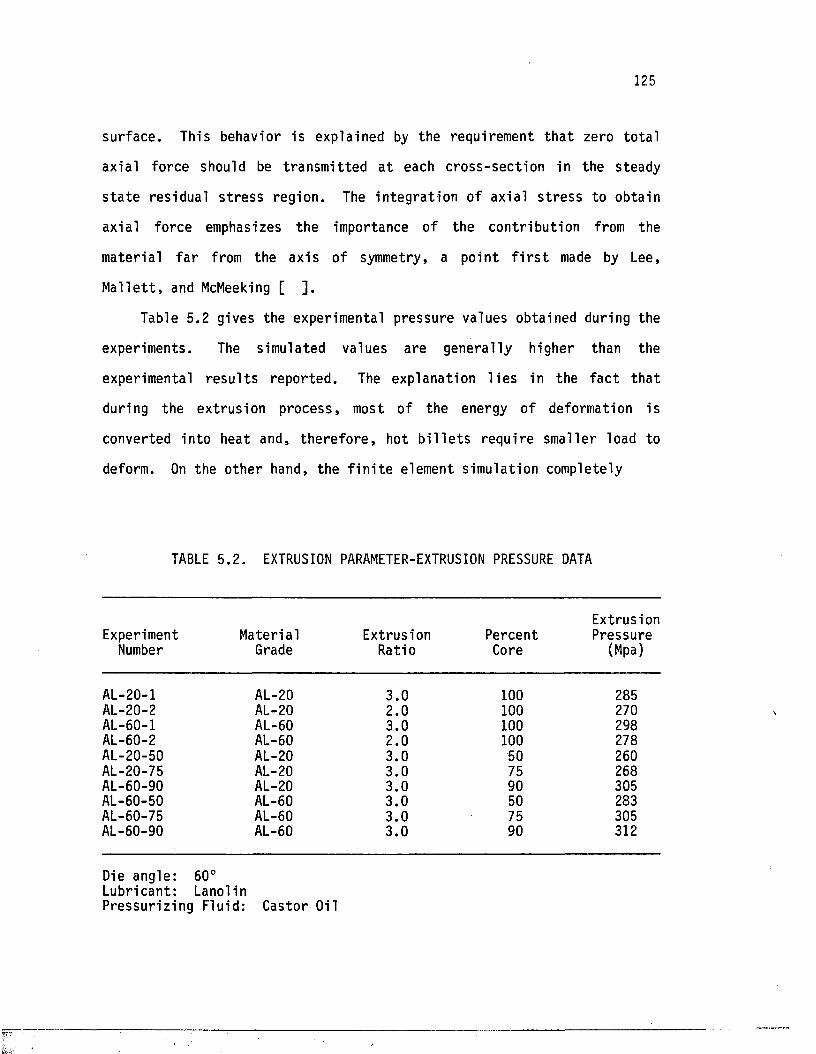
125
surface . This behavior is explained by the requirement th a t zero to ta l
axia l force should be t ransm it ted a t each c ross -sec t ion in the steady
s t a t e res idual s t r e s s region . The in teg ra t ion of axial s t r e s s to obtain
axial force emphasizes the importance of the contr ibut ion from the
mater ia l f a r from the axis of symmetry, a poin t f i r s t made by Lee,
M a l le t t , and McMeeking [ ] .
Table 5.2 gives the experimental pressure values obtained during the
experiments. The simulated values are generally higher than the
experimental r e s u l t s reported . The explanation l i e s in the f a c t tha t
during the extrus ion process , most of the energy of deformation is
converted in to heat and, th e re fo re , hot b i l l e t s require smaller load to
deform. On the o ther hand, the f i n i t e element simulation completely
TABLE 5.2. EXTRUSION PARAMETER-EXTRUSION PRESSURE DATA
ExperimentNumber
MaterialGrade
ExtrusionRatio
PercentCore
ExtrusionPressure
(Mpa)
AL-20-1 AL-20 3.0 100 285AL-20-2 AL-20 2.0 100 270AL-60-1 AL-60 3.0 100 298AL-60-2 AL-60 2.0 100 278AL-20-50 AL-20 3.0 50 260AL-20-75 AL-20 3.0 75 268,AL-60-90 AL-20 3.0 90 305AL-60-50 AL-60 3.0 50 283AL-60-75 AL-60 3.0 75 305AL-60-90 AL-60 3.0 90 312
Die angle: 60°Lubricant: LanolinPressur iz ing Fluid: Castor Oil
ignores the temperature e f f e c t and, consequently, no considera tion heat
is incorporated in to the numerical r e s u l t s .
5.3 EFFECT OF THE PROCESS VARIABLES
The e f f e c t of the process va r iab les and material composition on the
extrus ion pressure i s c lea r from the r e s u l t s of previous sec t ions . In
f a c t , Figures 5.1.31 and 5.1.32 show the va r ia t ion of extrusion pressure
with extrus ion r a t i o . As the figures in d ic a te , fo r a given die angle the
extrus ion pressure increases l i n e a r ly with the natura l logarithm of the
extrus ion r a t i o , i . e . , the higher the extrusion r a t i o , the higher the
extrus ion pressure . I t i s a lso evident th a t the pressure increases with
an increase in volume of the core m a te r ia l . This i s expected and is due
to the f a c t th a t the core materia l is harder than the copper cladding and
th e re fo re , i t requires more pressure to extrude.
The e f f e c t of die angle on the pressure can be seen from Table 5.1.
At a l l extrusion r a t i o s , the extrus ion pressure is higher fo r a die angle
of 60° than i t s corresponding value fo r a die angle of 45°.
Unfortunately, t h i s f ina l point cannot be concluded from the experimental
r e s u l t s since a l l experiments were conducted a t a die angle of 60°. In
p ra c t ic e , however, the smal ler die angle may have some inverse e f f e c t , as
t h i s decrease would be o f f s e t by the increase in f r i c t i o n due to the
g rea te r length of the low-angle die fo r the same extrus ion r a t i o .
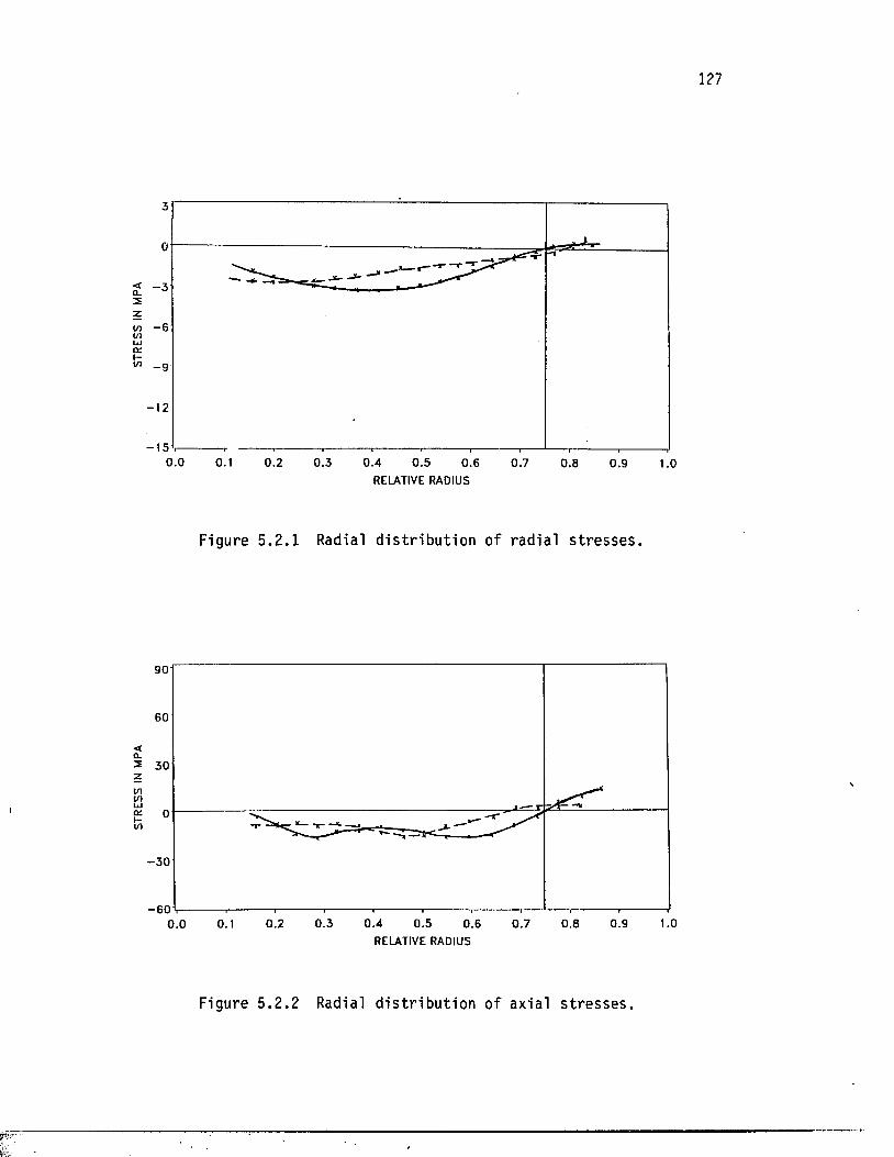
STRE
SS
IN MP
A ST
RESS
IN
MPA
- 6
- 9
- 1 50.0 0.1 0.3 0.4 0.50.2 0.6 0.7 0.8 0.9 1.0
RELATIVE RADIUS
Figure 5.2 .1 Radial d i s t r i b u t io n of rad ia l s t r e s s e s .
—r** - .._*—
0.0 0.1 0.2 0.3 0 .4 0.5 0.6 0.7 0.8 0.9 1.0RELATIVE RADIUS
Figure 5 .2 .2 Radial d is tr ib u t io n o f ax ia l stresses.
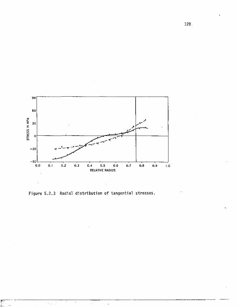
STRE
SS
IN M
PA128
S'
__» r- ~ y
S✓
- r
u i ----------------------1------ ,----------------------1 ■ , i , .................. ................ ., —
0.0 0.1 0.2 0.3 0 .4 0.5 0.6 0.7 0.8 0.9 1.0RELATIVE RADIUS
Figure 5 .2 .3 Radial d i s t r i b u t i o n of tangent ia l s t r e s s e s .
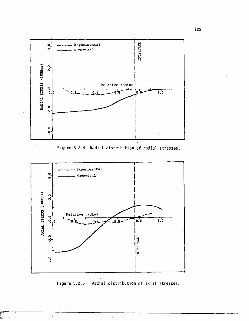
E x p e r i m e n t a lN u m e r ic a l
H
CM
O
R e l a t i v e r a d i u so
•CM
O
Figure 5 .2 .4 Radial d i s t r i b u t io n of radia l s t r e s s e s .
ExperimentalNumericalo
o
Relative radius
H
M
Figure 5 .2 .5 Radial d is tr ib u t io n o f axia l stresses.
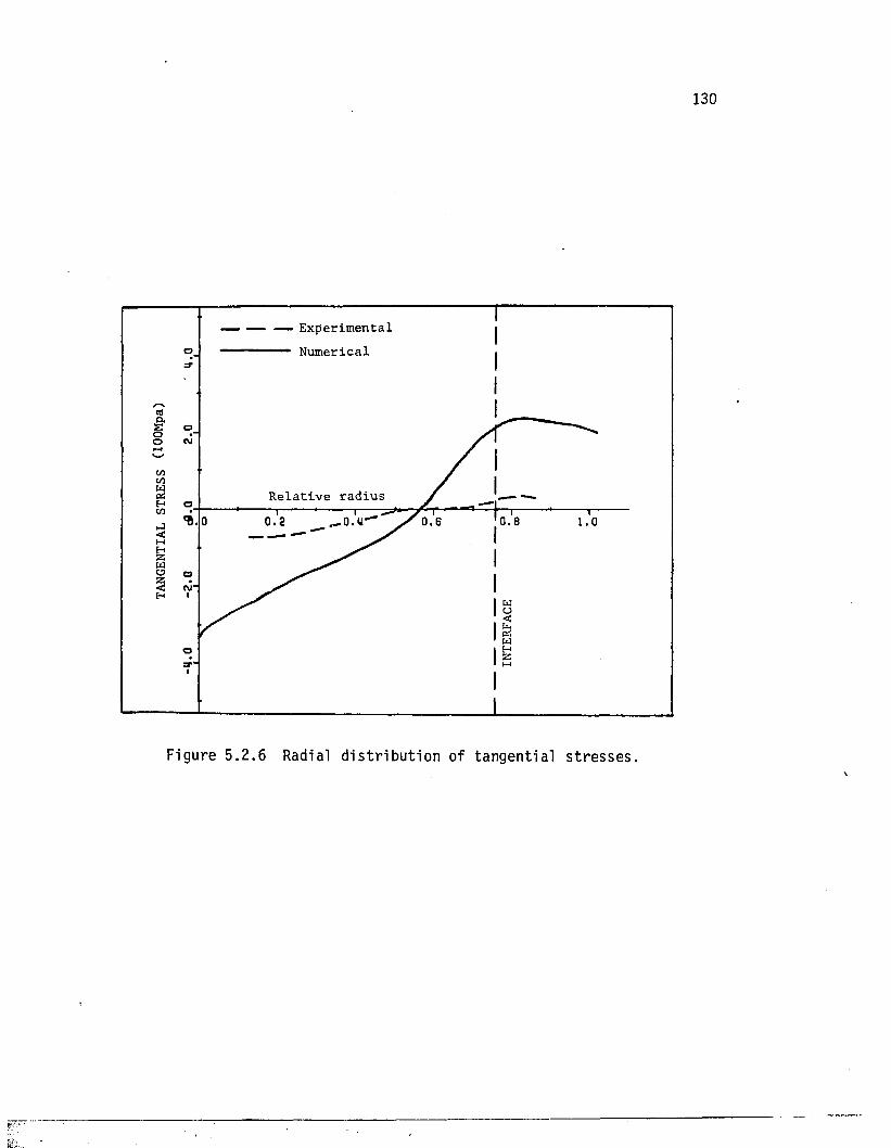
130
E x p e r i m e n t a l
N u m e r i c a lo
oCM
R e l a t i v e r a d i u so
a*'
Figure 5 .2 .6 Radial d i s t r i b u t io n of tangent ia l s t r e s s e s .
CHAPTER 6
CONCLUSIONS
6.1 EXTRUSION PRESSURE
Extrusion pressure r e s u l t s obtained show th a t the ext rusion pressure
increases l i n e a r ly with the natural logarithm of the extrusion r a t i o .
Also, higher pressure values are associa ted with higher die angles . The
simulation r e s u l t s are generally g rea te r than the experimental r e s u l t s .
6.2 RESIDUAL STRESSES
Radial res idual s t r e s s e s are compressive throughout the thickness of
the product, while the axia l and tangent ia l components o f s t r e s s are
compressive in the core and t e n s i l e in the c lad . The magnitude of the
rad ia l s t r e s s e s , however, is smaller than th a t of the axia l and
tangen t ia l s t r e s s e s .
The simulation values obtained fo r a l l components of res idual
s t r e s s e s are higher than in the experimental r e s u l t s . The trend in most
is the same.
The r e s u l t s ind ica te the con t inu i ty of the s t r e s s pa t te rns across
the i n t e r fa c e . This is due to the s im i l a r i t y in the cons t i tu en ts .
131
REFERENCES
101 Pearson, C.E., Extrusion of Metals, John Wiley & Sons, I n c . , London, pp. 5-9, 1944.
102 P e te rs , F .P . , "Producing Lead fo r Chemical Equipment," Met. I n d . , vol. 56, pp. 436,-438, 1940.
103 "Collected Experimental Papers o f P.W. Bridgman," Harvard Universi ty Press , 1964.
104 Hydrostatic Extrusion--Theory and A pp l ica t ions , N. Inoue and M. Nishihara, Eds. , E l sev ie r , London, 1985, p. 1.
105 Fuchs, F . J . , The Wire J o u rn a l , Oct. 1960, pp. 105-113.
106 Vodar, B. and J . K ie f fe r , The Mechanical Behavior of Materia ls Under P ressu re , Edited by H.H.D. Pugh, Applied Science Publ i shers , 1971, pp. 1-53.
107 Beresner, B . J . , L.R. Veveshchagin, Yu. N., Izv. Akad. Nank SSSR, O td l . Tech. Nank, 5 , 1957, pp. 48-55.
108 Vodar and K ie f fe r , Ibid .
109 Laue, K. and H. Stenger , Ext rusion , American Society fo r Metals, Ohio, p. 5, 1981.
110 But le r , L.H., "The Effec t o f Lubricants on the Growth of Surface Contact Areas During P la s t i c Deformation of Metals," J . I n s t . Meta ls , 89:116, 1960.
111 Williams, C.G., "Mechanism of the Action of Extreme Pressure Lubr icants , Proc. Royal Socie ty , 212A, p. 512, 1952. -
112 Leland, J .F . and J.W. Helms, "Troubles with Cold Extrusion May Be Traced to Lubr ica t ion ," SAE J o u rn a l , p. 43, Nobember 1954.
113 Laue and Stenger, I b i d . , p. 89.
114 Ib id .
115 I b i d . , p. 98.
116 Massat, H. and B. Vodar, "Forming and Extrusion Apparatus with Accurate Pressure Control Up to 20 kbar ," Hydrostat ic Ext rusion , H.L.D. Pugh, Ed,, Mechanical Engineering Pub l ica t ions , London, pp. 59-71, 1974.
201 Bridgman, P.W., Physics of High P ressu re , In t . Textbooks of Exact Sciences, Gr. Bells and Sans, L td . , London, 1949.
132
133
202 "Collected Experimental Papers of P.W. Bridgman," Ibid .
203 Hy d ro s ta t i c Extrusion—Theory and Appl ica t ions , Ib id . Nishihara,
204 Beresner and Veveshchagin, Ibid.
205 Vodar and Kie f fe r , Ib id .
206 Nishihara , M., K. Tanaka and T. Muramatsu, Proc. 75h Japan Cong.Test . Mat. , vo l. 7, p. 154, 1964.
207 Nishihara, M., e t . a l , Proc. 8th Japan Cong. Test . Mat. , vol. 8, p. 73, 1965.
208 Nishihara, M., K. Tanaka, S. Yamamoto and Y. Yamaguchi, J . Soc.Materia ls Science, Japan, vol. 16, pp. 169-173, 1967.
209 Nishihara , M., K. Tanaka, S. Yamamoto and Y. Yamaguchi, Proc. 10th Japan Cong. Tes t . Mat. , vol. 10, pp. 50-53, 1967.
210 Nishihara, M., and K. Izawa, Science and Engineering Review ofDoshisha Univers ity , vol. 9, pp. 41-64, 1968.
211 Nishihara, M., P rep r in t s , NEL/AIRAPT In te rna t iona l Conference onHydrostatic Extrusion, Univ. S t i r l i n g , Scotland, 1973, pp. 33-81.
212 Fuchs, Ibid.
213 Green, D., Journal of the I n s t i t u t e of Metals, vo l. 100, pp. 295-300, 1972.
214 Black, J .T . and W.G. Voorhes, Journal of Engineering fo r Indus t ry , Trans. ASME, vol. 100, pp. 37-42, 1978.
215 Avitzur, B., The Wire J o u rn a l , pp. 73-80, Ju ly 1975.
216 Nishihara , M., T. Matsushita and Y. Yamaguchi, P rep r in t s , 14th Annual Meeting of European High Pressure Research Group, Dublin, Ir e land , Sept. 6-8 , 1976.
217 Inoue, N., and M. Nishihara , Hydrostatic Extrusion, Chapter 2, E lsev ie r , London, 1985.
218 I b i d . , pp. 21-40.
219 Johnson, W. and H. Kudo, The Mechanics of Metal Extrusion, Manchester University Press , 1962.
220 Ewing, D .J .F . , J . Mech. Phys. S o l id s , vol. 15, pp. 105-114, 1967.
221 Col l ins , I . F . , Proc. Roy. Soc. London, A-303, pp. 217-338, 1968.
222 Osakada, K. and Y. Niimi, In t . J . Mech. S c i . , vol. 17, pp. 241-254, 1975.
134
223 Yamaguchi, M., T. Matsushita, M. Nuguchi, and T. F u j i t a , Proc. 1972 Japanese Spring Conf. Tech. P l a s t i c i t y , Nagoya, May 11-13, pp. 69-72
224 Johnson and Kudo, Ibid.
225 Hydrostatic Extrusion—Theory and A pp l ica t ions , p. 13.
226 Avitzur, B., R. Wu, S. Ta lbe r t and Y.T. Chou, "Cri te r ion for Prevention of Core Fracture During Extrusion of Bimetal Rods," J . Eng. In d . , Trans. ASME Series B, vol. 104, pp. 293-304, 1982.
227 Lowenstein, P.W. and W.B. Tuff in , "Metallurgical Bonding of Dissimila r Metals by Co-extrusion," Met. Eng. Quart , vol. 4, pp. 26-31, 1964.
228 Blazynski, T.Z. and M. Matin, "The Response of Implosively Prewelded Arrays of Rods to Processing by Hydrostatic Extrus ion," J . Mech. Work. Techno! . , vol. 6, pp. 291-302, 1982.
229 Dull, D., E.B. Kendall and L. Raymond, "Ti-Be Composite Produced by Co-extrusion of Powder," Mater ia ls Technology - An Interamerican Approach fo r the 70s, ASMF̂ United Engineering Center, New York, 1970.
230 Johnsson, S . , "Recent Developments in Hydrostatic Extrusion," Wire World I n t i . , vo l. 11, pp. 23-27, 1969.
231 Alexander, J .M. , "Hydrostatic Extrusion--The S ta te of the Art ," CME, vol. 9, pp. 108-111, 1973.
232 Pacheco, L.A. and J.M. Alexander, "On the Hydrostatic Extrusion of Copper-covered Aluminum Rods," Numerical Methods in Indus t r ia l Forming Processes , J .F .T . Pit tman, R.D. Wood, J.M. Alexander and O.C. Zeinkeiwicz, Eds. , Pineridge Press , Swansea, U.K., pp. 205-216, 1982.
233 K. Osakada, M. Limb and P.B. Mellor, "Hydrostatic Extrusion of Composite Rods with Hard Cores," In t . J . Mech. S c i . , vol. 15, pp. 291-307, 1973.
234 Hartley, C .S. , "Upper Bound Analysis of Extrusion of Axisymmetric Piecewise Homegeneous Tubes," In t . J . Mech. S c i . , vo l. 15, pp. 651-663, 1973.
235 Lee, E.H., R.L. Mal le t t and R.M. McMeeking, "Stress and Deformation Analysis of Metal Forming Processes ," Numerical Modeling of Manu- fac tu r ing Processes, PVP-PB-025, R.F. Jones, J r . , H. Armen and J .T . Fond, Eds . , ASME, New York, pp. 19-33, 1977.
236 Alexander, J.M. and B. Lengyel, Hydrostatic Ext rusion , Mills and Boon, London, 1971.
135
237 Alexander, J.M. and C.S. Hartley, "On the Hydrostatic Extrusion of Copper-covered Aluminum Rods," Hydrostatic Extrusion, H. L7, D. Pugh, Ed., Mechanical Engineering Publ ica t ions , London, pp. 72-78, 1974.
238 Lugosi, R., C.S. Hartley and A.T. Male, "The Influence of I n te r f a c ia l Shear Yield Strength on the Deformation Mechanics o f an Axi-Symmetric Two-Component System," Westinghouse Research Lab. Tech. Document No. 77-1D4-PR0EN-P1, 1977.
239 Hartley, C.S. and R. Sr in ivasan , "Const i tu t ive Equations fo r Large P la s t i c Deformation of Metals," J . Eng. Mat. Technol. , vol. 105, pp. 162-167, 1983.
240 Avitzur, B., "Analysis o f Wire Drawing and Extrusions Through Conical Dies of a Large Cone Angle," J . Eng. In d . , Trans. ASME Series B, vol. 87, pp. 89-96, 1965.
241 Avitzur , B., "Hydrostatic Extrus ion," J . Eng. Ind. Trans. ASME Series B, vol. 87, pp. 487-493, 1965.
242 Osakada, K., J . Nakano and K. Mori, "F in i te Element Method for R ig id -p la s t ic Analysis of Metal Forming--Formulation fo r F in i te Deformation," In t . J . Mech. S c i . , vo l. 24, pp. 459-468, 1982.
243 Avitzur, B., Metal Forming: Processes and Analysis , Tata-McGraw- H i l l , New Delhi, 1977.
244 Osakada, K. and P.B. Mellor, In t . J . Mech. S c i . , vo l. 15, pp. 291-307, 1973.
245 Prager, W. and P.G. Hodge, J r . , Theory of Per fec t ly P la s t i c S o l id s , Chapman & Hall , L td . , London, 195II
246 Avitzur, B., "The Production of Bi-metal Rod and Wire," The Wire Jo u rn a l , vol. 3, pp. 42-49, 1970.
301 McHenry, D., "A L a t t ice Analogy fo r the Solution of Plane St ress Problems," J . I n s t . Civ. Eng., vol. 21, pp. 59-82, 1943.
302 Newmark, N.M., "Numerical Methods of Analysis in Bars, P la te s , and E las t i c Bodies," Numerical Methods in Analysis in Engineering, L.E. Grin tner , Ed., Macmillan, 1949.
303 Hrenikoff, A., "Solution of Problems in E l a s t i c i t y by the Framework Method," J . Appl. Mech., A8, pp. 169-175, 1941.
304 Turner, M.J. , R.W. Clough, H.C. Martin, and L .J . Topp, "S t i f fne ss and Deflection Analysis of Complex S t ru c tu res , " J . Aero. S c i . , 23:9, pp. 805-823, 1956.
305 Clough, R.W., "The F in i te Element in Plane S tress Analysis ," Proc. 2nd ASCE Conf. on Elec t ron ic Computation, P i t t sburgh , Pa . , Sept. 1960.
306
307
308
309
310
311
312
313
314
315
316
317
318
319
320
136
Melosh, R . J . , "Struc tura l Analysis o f S o l ids ," Proc. ASCE, ST4, pp. 205-223, Aug. 1963.
Zienkiewicz, O.C. and Y.K. Cheung, "F in i te Elements in the Solution of Fie ld Problems, The Engineer, pp. 507-510, 1965.
Wilson, E.L. and R.E. Nickel ! , "Application of F in i te Element Method to Heat Conduction Analysis ," Nucl. Eng. Design, vol. 4, pp. 1-11, 1966.
Visser, W., "A F in i te Element Method for the Determination of Non- s t a t io n a r y Temperature D is t r ibu t ion and Thermal Deformations," Proc. Conf. on Matrix Methods in S t ruc tu ra l Mechanics, Air Force Ins t . Tech., Wright-Patterson Air Field Base, Ohio, 1965.
Ghaboussi, J . and E.L. Wilson, "Flow of Compressible Fluids in E las t ic Media," In t . J . Num. Meth. Eng., vol. 5, pp. 419-442, 1973.
ABAQUS: A General Purpose Nonlinear F in i te Element Program, Hibbi t , Karlsson, and Sorensen, In c . , 1982.
Chandra, A. and S. Mukherjee, "Boundary Element Formulations fo r Large S t r a i n —Large Deformation Problems of V is co p la s t i c i ty , " In t . J . Solids S t r u c t u r e s , 20:1, pp. 41-53, 1984.
Osias, J .R. and J .L . Swedlow, "F in i te E la s to - p l a s t i c Deformation: I-Theory and Numerical Examples," In t . J . Solids S t ruc tu res , vo l. 10, pp. 321-339, 1974.
Lee, E.H., "E la s to -p la s t i c Deformation a t F in i te S t r a i n s , " J . Appl. Mech., vol. 36, pp. 1-6, 1969.
H ibbit , H.D., P.V. Marcal, and J.R. Rice, "A Fin i te Element Formulation fo r Problems of Large S t ra in and Large Displacement," In t . J . Solids S t r u c t u r e s , vo l. 6, pp. 1069-1086, 1970.
Nagtegaal, J .C. and J .E . De Jong, "Some Computational Aspects of E l a s t i c - p l a s t i c Large S tra in Analysis ," In t . J . Num. Meth. Eng., vo l. 17, pp. 15-41, 1981.
Turner, M.J. , E.H. D i l l , H.C. Martin, and R.J. Melosh, "Large Deflections o f S t ructures Subjected to Heating and External Loads," J . Aerospace S c i . , vol. 27, pp. 97-102, 1960.
Nemat-Nasser, S . , "Decomposition of S t ra in Measures and Their Rates in F in i te Deformation E l a s t o p l a s t i c i t y , " In t . J . Solids S t ruc tu res , vol. 15, pp. 155-166, 1979.
Lee, E.H. and R.M. McMeeking, "Concerning E la s t i c and P la s t i c Components of Deformation," In t . J . Solids S t ru c tu re s , vol. 16, pp. 715-721, 1980.
Lee, E.H., "Analyses of the Propagation of Plane E l a s t i c - p l a s t i c Waves of F in i te S t r a i n , " J . Appl. Mech., vol. 34, pp. 931-936, 1967.
137
321 Lee, E.H., R.L. M al le t t , and R.M. McMeeking, "Stress and Deformation Analysis o f Metal Forming Processes," Numerical Modeling of Manufacturing Processes , PVP-PB-025, R.F. Jones, H. Armen, and J .T . Fong, Eds. , ASME, pp. 19-33, 1977.
322 McMeeking, R.M. and J .R . Rice, "F in i te Element Formulations for Problems of Large E l a s t i c - p l a s t i c Deformation," In t . J . Solids S t r u c t u r e s , vol. 11, pp. 601-616, 1975.
323 Lee, E.H. and R.L. M al l e t t , "Stress and Deformation Analysis of the Metal Extrusion Process," Comp. Meth. in Appl. Mech. Engr. , vol. 10, pp. 339-353, 1977.
324 ABAQUS: Theory Manual, Ibid .
325 Lubarda, V.A. and E.H. Lee, "A Correct Definit ion of E las t ic and P la s t i c Deformation and I t s Computational S ign i f icance ," J . Appl. Mech., vol . 48, 35-40, 1981.
326 Yamada, Y., N. Yoshimura, and T. Sakurai , "P la s t i c St ress St rain Matrix and I t s Application fo r the Solution of E l a s t i c - p l a s t i c Problems by the F in i te Element Method," In t . J . Mech. S c i . , vol. 10, 1968.
327 Ramm, E., "S t ra teg ie s fo r Tracing the Nonlinear Response Near Limit Po in ts ," Nonlinear F in i te Element Analysis in St ructura l Mechanics, W. Wunde!ich, IT S te in , and K.J. Bathe, Eds . , Springer-Verlag, Ber l in , 1981.
401 Lovic, W.R., N.C. Iye r , and A.T. Male, "Deformation Processing by Hydrostatic Co-extrusion: Status Report," Westinghouse R & D CenterReport No. 81-2D4-C0DEF-R1, 1981.
402 Sachs, G., "Der Nachwies innerer Spannungen in Stangen und Rohren," Z. Metal! . , vol . 19, pp. 352-357, 1927.
403 Lambert, J .W., "A Method of Deriving Residual S tress Equations," Experimental S t ress Analysis , vol. 12, pp. 91-96, 1954.
404 Timoshenko, S. and Goodier, Theory of E l a s t i c i t y , New York, McGraw- H i l l , 1951.
405 Kato, B. and H. Aoki, "Residual S tresses in Cold Formed Tubes," J . of S t ra in Analysis , vol. 13, pp. 193-204, 1978.
406 Springborn, R.K., Ed., Non-t radit ional Machining Processes , ASME, Dearborn, Mich., 1967.
407 Hoare, J . and M. LaBoda, "Electrochemical Machining," Technigues of Electrochemistry , Vol. 3 , E. Yeager and A.J. Salkindl Eds. , John Wiley & Sons, New York, pp. 48-104, 1978.
408 McGeough, J .A . , P r inc ip les of Electrochemical Machining, Chapman & Hall , London, 1973”
VITA
Mohammad Dehghani was born on August 22, 1955, in Tehran, Iran. After completing primary and secondary education in Tehran's high schools , he jo ined the I ranian armed forces in November 1975.
In June 1977 he entered Louisiana S ta te Universi ty in Baton Rouge, Louisiana. He earned his B.S. degree in December 1980 and his M.S. degree in August 1982, both in Mechanical Engineering. He then beganthe Ph.D. program in Mechanical Engineering.
138
D O C T O R A L E X A M IN A T IO N A N D D IS S E R T A T IO N R E P O R T
Candidate: Mohammad M. Dehghani
Major Field: Mechanical Engineering
Title o f Dissertation: Computer Simulation of Hydrostatic Co-Extrusion of Bimetall icCompounds
Approved:
tajor Professor and Chairman
Dean of the Graduate Spnool
EX A M IN IN G COM M ITTEE:
Date of Examination:
June 29, 1987