Embed Size (px)
Citation preview
You have a vision ...
PEAK-System Technik
You are working on the future of your company and
planning successful products for tomorrow‘s markets?
You want to translate your projects into reality, so you
look for a responsive and reliable partner?
You set great importance to the functionality of your
development tools and the quality of the hardware you
use?
Whether you need a plug-in card for the PC, a
microcontroller module for temperature recording, a
program to monitor your system, or just the right kind of
cable –
with our product range we can help you concentrate on
what is important to you: developing successful products.
PEAK-System Technik puts creative teams of experienced
and highly-motivated specialists at your disposal, open to
new ways, open to new solutions. Talk over your aims and
objectives with us.
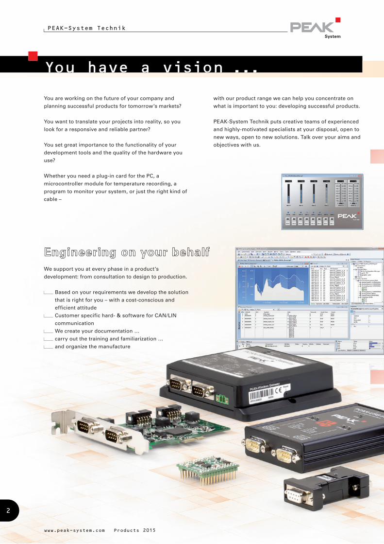
We support you at every phase in a product‘s
development: from consultation to design to production.
Based on your requirements we develop the solution
that is right for you – with a cost-conscious and
efficient attitude
Customer specific hard- & software for CAN/LIN
communication
We create your documentation …
carry out the training and familiarization …
and organize the manufacture
www.peak-system.com Products 2015
2

... we do the rest.
PEAK-System Technik
CAN FD connections for High-speed USB 2.0
CAN/LIN interfaces for conventional PC interfaces and
embedded applications
I/O modules with CAN connection for control,
measured data recording, and processing
Converters for different physical transmission types
(bus converter modules)
Routers and gateways for the forwarding of messages
between CAN busses and other networks
Data loggers and diagnostic hardware
Products for education, demonstrations, and test
setups
Chip solutions for the CAN connection to
USB, PCI, and PCI Express
CAN development systems for
Windows 8.1, 7, Vista, CE 6.x and for Linux
Programming interfaces for various protocols and
standards
Software to monitor and diagnose CAN and LIN
busses
Programs for recording, playback, and simulation of
message traffic
Configuration software for CAN hardware from
PEAK-System
Helpful CAN accessories
PC adapter cards for PC/104 Small Form Factor Boards
CAN cables and adapters for various applications
One of our products fits your portfolio?
Your development department is under pressure?
We have the ideal solution for you:
Adaptation of our products to your specific needs
Available as customer OEM product
(your logo, your case)
Translation of your ideas into
ready-to-manufacture products
Advice and consultation on hardware and
software development
Fixed-price development on your behalf
www.peak-system.com Products 2015
3

Preview 2015
PEAK-System Technik
www.peak-system.com Products 2015
With the release of various PC interfaces and software
products, PEAK-System is a pioneer in the introduction of
the new CAN FD standard.
With CAN FD (Flexible Data rate) the robust and long-
lasting CAN specification has been extended with
properties which are primarily designed for larger
amounts of data. Higher bit rates up to 12 Mbit/s for the
data of the CAN frames and the use of up to 64 data bytes
in a single CAN frame are the main criteria.
CAN FD is downward-compatible to the CAN 2.0 A/B
standard, thus CAN FD nodes can be used in existing CAN
networks. However, in this case the CAN FD extensions
are not applicable.
Since the first implementations of CAN FD, the protocol
has been improved and is now included in the standard
ISO 11898-1. The revised CAN FD standard is not
compatible with the original protocol. PEAK-System takes
this into account by supporting both protocol versions
with their CAN FD interfaces. If required, the user can
switch to the CAN FD protocol used in the environment by
software („Non-ISO“ and „ISO“).
PEAK-System enhances its CAN product range step by
step with CAN FD ability. Our CAN interfaces for the USB
port are already available with CAN FD support and will
be complemented by the 6-channel version PCAN-USB X6
in 2015. The integration of CAN FD connectivity in custom
hardware designs can be achieved with the Stamp module
PCAN-Chip USB.
For the range of plug-in cards the implementation
of the new standard starts with the PCI Express slot.
A counterpart to the existing, freely programmable
PCAN-Router for routing two CAN FD channels is in
development.
For the third quarter of 2015, the publication of the
completely revised PCAN-Explorer 6 is scheduled.
During the same period the PCAN-Developer package for
Windows for developing extensive software projects with
CAN FD connection will be released.
If you are interested, please observe the press releases
and news about product releases on the PEAK-System
website.
4

PEAK-System Technik
www.peak-system.com Products 2015
Version 6 of the comprehensive Windows software
for monitoring and analyzing CAN data traffic will be
enhanced in addition to the CAN FD support by many
new features such as ...
Extensive revision of the user interface with improved
dialogs for creating transmit messages and managing
signals
Simultaneous connections with mutliple CAN
interfaces independent of the hardware type
Playback of trace files
Direct recording of the CAN data traffic into files with
the option to spilt them during the tracing process
Enhanced processing of huge trace files
Exporting entire projects including linked files to
handy data packets for archiving or sharing
Automatic notification about new software versions
and support with the update process
Various improvements of the PCAN-Explorer add-ins ...
Plotter add-in: Decoupling the configuration of Y-axis
and channels to improve presentation and handling
Instruments Panel add-in: New instruments like
an analog 360° display and a shape element for
displaying squares, rectangles, circles, and ellipses
A new version of the PCAN-Symbol Editor with many
enhancements will be released as well ...
New user interface with Quick Start function
Allows for the first time to create signals in
symbol files
With a signal the representation of CAN data can be
defined and used for multiple symbols
Function to convert symbol files between their
different file formats
Dynamic text search for symbols, signals, menu
commands, recently opened files, and more
The PCAN-Explorer 6 is expected to be available in the
third quarter of 2015.
5

PEAK-System Technik
HARDWAREPC Interfaces
PCAN-USB FD 11
PCAN-USB Pro FD 12
PCAN-USB X6 14
PCAN-USB 16
PCAN-USB Hub 17
PCAN-PCI 18
PCAN-PCI Express 19
PCAN-cPCI 20
PCAN-miniPCI 21
PCAN-miniPCIe 22
PCAN-PC/104 23
PCAN-PC/104-Plus 24
PCAN-PC/104-Plus Quad 25
PCAN-PCI/104-Express 26
PCAN-ExpressCard 34 27
PCAN-ExpressCard 28
PCAN-PC Card 29
PCAN-ISA 30
PCAN-Dongle 31
Chip Solutions
PCAN-Chip PCI & PCIe 32
PCAN-Chip USB 33
PCAN-Chip USB Eval 33
Couplers & Converters
PCAN-Optoadapter 34
PCAN-Repeater DR 35
PCAN-LWL 36
PLIN-LWL 37
PCAN-AU5790 38
PCAN-B10011S 39
PCAN-TJA1054 40
I/O Modules
PCAN-MicroMod 41
PCAN-MicroMod Evaluation Board 41
PCAN-MicroMod Analog 1 & 2 42
PCAN-MicroMod Digital 1 & 2 43
PCAN-MicroMod Mix 1 44
PCAN-MicroMod Mix 2 45
PCAN-MicroMod Mix 3 46
PCAN-MIO 47
MU-Thermocouple1 CAN 48
PLIN-Slave 49
PCAN-GPS 50
PEAK-gridARM Evaluation Board 51
Routers & Gateways
PCAN-Gateways 52
PCAN-Gateway Applications 54
Virtual PCAN-Gateway 56
PCAN-Wireless Gateway 57
PCAN-Wireless Gateway DR 58
PCAN-Ethernet Gateway DR 59
PCAN-RS-232 60
PCAN-Router 61
PCAN-Router Pro 62
PCAN-Router DR 64
PCAN-LIN 65
PCAN-GPRS Link 66
Diagnostics & Education
PCAN-Diag 2 68
PCAN-MiniDisplay 71
Serial Bus Simulator 72
A constantly updated overview of our products can be found at . . .6
PEAK-System Technik
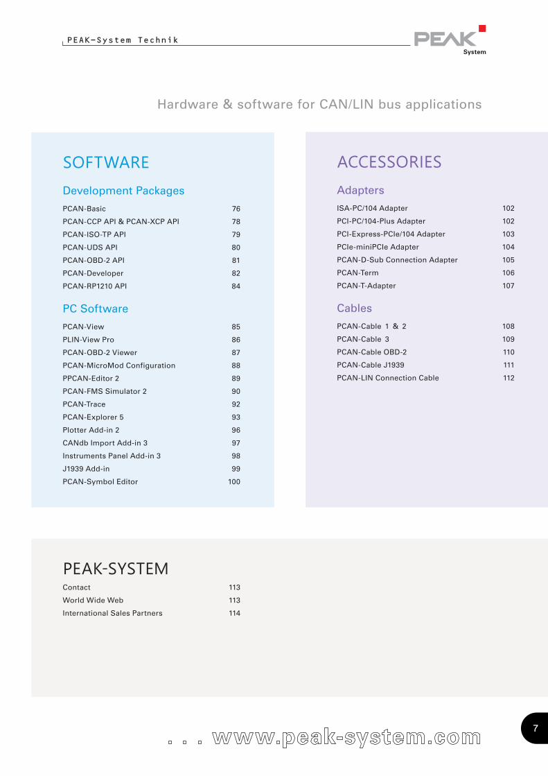
ACCESSORIESAdapters
ISA-PC/104 Adapter 102
PCI-PC/104-Plus Adapter 102
PCI-Express-PCIe/104 Adapter 103
PCIe-miniPCIe Adapter 104
PCAN-D-Sub Connection Adapter 105
PCAN-Term 106
PCAN-T-Adapter 107
Cables
PCAN-Cable 1 & 2 108
PCAN-Cable 3 109
PCAN-Cable OBD-2 110
PCAN-Cable J1939 111
PCAN-LIN Connection Cable 112
SOFTWARE Development Packages
PCAN-Basic 76
PCAN-CCP API & PCAN-XCP API 78
PCAN-ISO-TP API 79
PCAN-UDS API 80
PCAN-OBD-2 API 81
PCAN-Developer 82
PCAN-RP1210 API 84
PC Software
PCAN-View 85
PLIN-View Pro 86
PCAN-OBD-2 Viewer 87
PCAN-MicroMod Configuration 88
PPCAN-Editor 2 89
PCAN-FMS Simulator 2 90
PCAN-Trace 92
PCAN-Explorer 5 93
Plotter Add-in 2 96
CANdb Import Add-in 3 97
Instruments Panel Add-in 3 98
J1939 Add-in 99
PCAN-Symbol Editor 100
PEAK-SYSTEMContact 113
World Wide Web 113
International Sales Partners 114
Hardware & software for CAN/LIN bus applications
7

PEAK-System Technik
We were successfully certified according to the
international standards ISO 9001:2008 and ISO 14001:2004
in October 2014. Our management system combines
the requirements of the standard ISO 9001 for quality
management systems and the ones of the standard
ISO 14001 for environmental management
systems.
With the certification, we
provide a documented proof
for our quality-conscious and
customer-oriented business
as well as our responsible
management of resources and
environment. The certification
was carried out by
DEKRA Certification GmbH.
The certificates are available
on our website in the languages
German, English, and French for
download.
Development, manufacturing and sales of hardware and software for applications in the mobile and industrial communication sector
www.peak-system.com Products 2015
We have our own products and customer-specific
OEM products produced by reputable manufacturing
companies in Germany and throughout Europe.
8
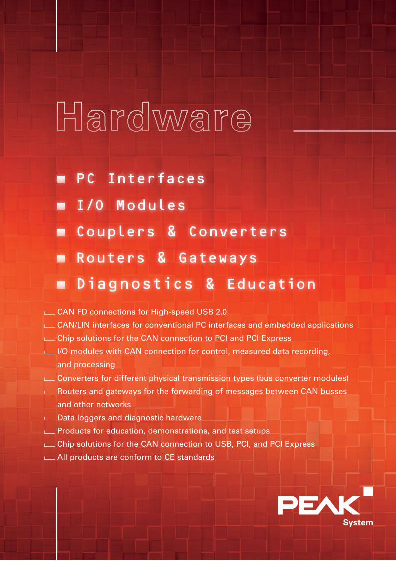
PC Interfaces
I/O Modules
Couplers & Converters
Routers & Gateways
Diagnostics & Education
CAN FD connections for High-speed USB 2.0
CAN/LIN interfaces for conventional PC interfaces and embedded applications
Chip solutions for the CAN connection to PCI and PCI Express
I/O modules with CAN connection for control, measured data recording,
and processing
Converters for different physical transmission types (bus converter modules)
Routers and gateways for the forwarding of messages between CAN busses
and other networks
Data loggers and diagnostic hardware
Products for education, demonstrations, and test setups
Chip solutions for the CAN connection to USB, PCI, and PCI Express
All products are conform to CE standards
www.peak-system.com Products 2015
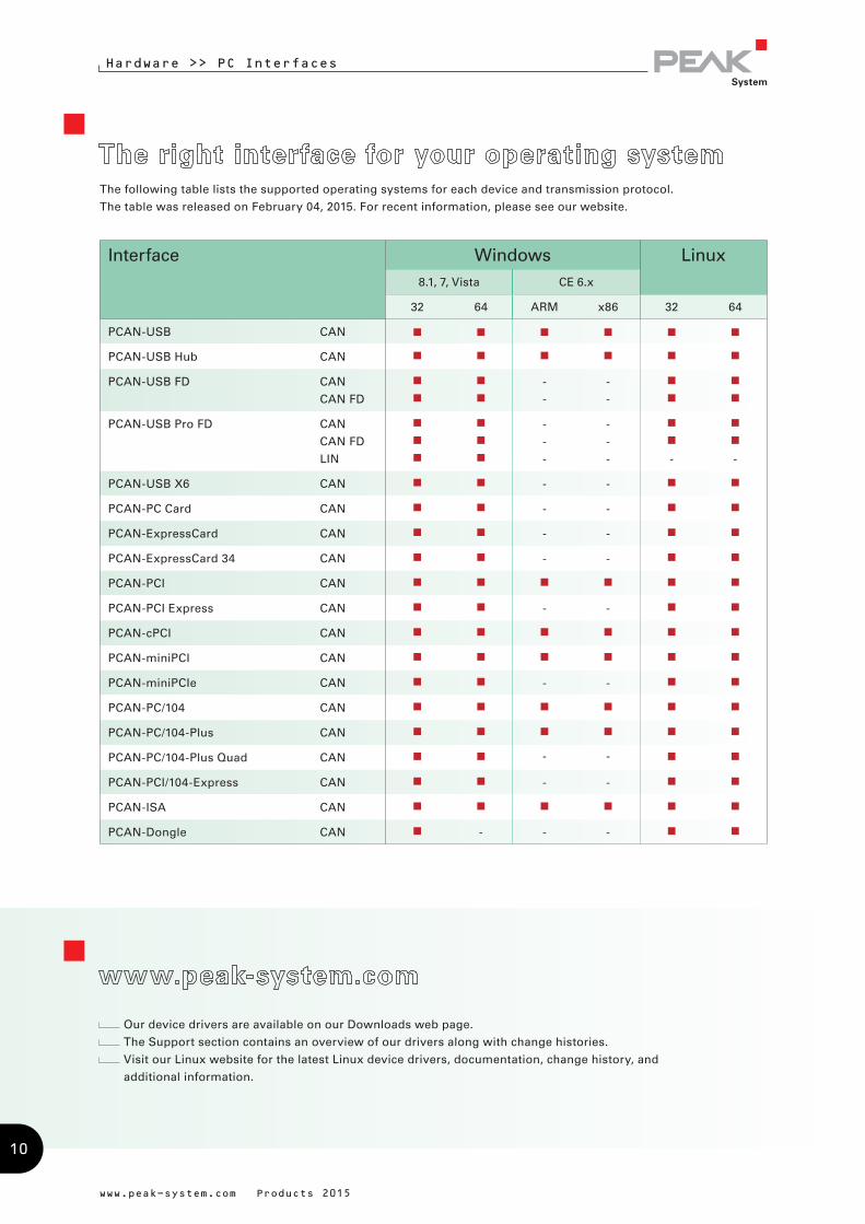
Hardware >> PC Interfaces
The following table lists the supported operating systems for each device and transmission protocol.
The table was released on February 04, 2015. For recent information, please see our website.
Our device drivers are available on our Downloads web page.
The Support section contains an overview of our drivers along with change histories.
Visit our Linux website for the latest Linux device drivers, documentation, change history, and
additional information.
Interface Windows Linux8.1, 7, Vista CE 6.x
32 64 ARM x86 32 64
PCAN-USB CAN
PCAN-USB Hub CAN
PCAN-USB FD CAN
CAN FD
-
-
-
-
PCAN-USB Pro FD CAN
CAN FD
LIN
-
-
-
-
-
- - -
PCAN-USB X6 CAN - -
PCAN-PC Card CAN - -
PCAN-ExpressCard CAN - -
PCAN-ExpressCard 34 CAN - -
PCAN-PCI CAN
PCAN-PCI Express CAN - -
PCAN-cPCI CAN
PCAN-miniPCI CAN
PCAN-miniPCIe CAN - -
PCAN-PC/104 CAN
PCAN-PC/104-Plus CAN
PCAN-PC/104-Plus Quad CAN - -
PCAN-PCI/104-Express CAN - -
PCAN-ISA CAN
PCAN-Dongle CAN - - -
10
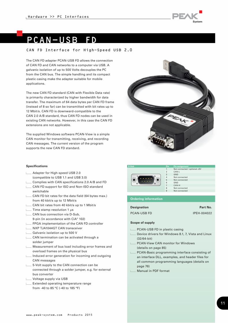
Designation Part No.
PCAN-USB FD IPEH-004022
Scope of supply
PCAN-USB FD in plastic casing
Device drivers for Windows 8.1, 7, Vista and Linux
(32/64-bit)
PCAN-View CAN monitor for Windows
(details on page 85)
PCAN-Basic programming interface consisting of
an interface DLL, examples, and header files for
all common programming languages (details on
page 76)
Manual in PDF format
Ordering information
D-Sub Pin Pin assignment1 Not connected / optional +5V2 CAN-L3 GND4 Not connected5 Not connected6 GND7 CAN-H8 Not connected9 Not connected
PCAN-USB FD
Hardware >> PC Interfaces
CAN FD Interface for High-Speed USB 2.0
www.peak-system.com Products 2015
Specifications
Adapter for High-speed USB 2.0
(compatible to USB 1.1 and USB 3.0)
Complies with CAN specifications 2.0 A/B and FD
CAN FD support for ISO and Non-ISO standard
switchable
CAN FD bit rates for the data field (64 bytes max.)
from 40 kbit/s up to 12 Mbit/s
CAN bit rates from 40 kbit/s up to 1 Mbit/s
Time stamp resolution 1 µs
CAN bus connection via D-Sub,
9-pin (in accordance with CiA® 102)
FPGA implementation of the CAN FD controller
NXP TJA1044GT CAN transceiver
Galvanic isolation up to 500 V
CAN termination can be activated through a
solder jumper
Measurement of bus load including error frames and
overload frames on the physical bus
Induced error generation for incoming and outgoing
CAN messages
5-Volt supply to the CAN connection can be
connected through a solder jumper, e.g. for external
bus converter
Voltage supply via USB
Extended operating temperature range
from -40 to 85 °C (-40 to 185 °F)
The CAN FD adapter PCAN-USB FD allows the connection
of CAN FD and CAN networks to a computer via USB. A
galvanic isolation of up to 500 Volts decouples the PC
from the CAN bus. The simple handling and its compact
plastic casing make the adapter suitable for mobile
applications.
The new CAN FD standard (CAN with Flexible Data rate)
is primarily characterized by higher bandwidth for data
transfer. The maximum of 64 data bytes per CAN FD frame
(instead of 8 so far) can be transmitted with bit rates up to
12 Mbit/s. CAN FD is downward-compatible to the
CAN 2.0 A/B standard, thus CAN FD nodes can be used in
existing CAN networks. However, in this case the CAN FD
extensions are not applicable.
The supplied Windows software PCAN-View is a simple
CAN monitor for transmitting, receiving, and recording
CAN messages. The current version of the program
supports the new CAN FD standard.
11
PCAN-USB Pro FD
Hardware >> PC Interfaces
CAN FD and LIN Interface for High-Speed USB 2.0
www.peak-system.com Products 2015
The monitor application PLIN-View Pro as well as the PLIN
programming interface are also included in the scope of
supply.
Specifications
Adapter for High-speed USB 2.0
(compatible to USB 1.1 and USB 3.0)
Transmitting and receiving of CAN FD and LIN
messages using 2 D-Sub connections (both with pin
assignment for the CAN FD and LIN bus)
Time stamp resolution 1 µs
5-Volt supply at the D-Sub connector can be activated
through a solder jumper, e.g. for external bus
converter
Voltage supply via USB
Extended operating temperature range
from -40 to 85 °C (-40 to 185 °F)
CAN operation properties:
Complies with CAN specifications 2.0 A/B and FD
CAN FD support for ISO and Non-ISO standard
switchable
CAN FD bit rates for the data field (64 bytes max.)
from 40 kbit/s up to 12 Mbit/s
CAN bit rates from 40 kbit/s up to 1 Mbit/s
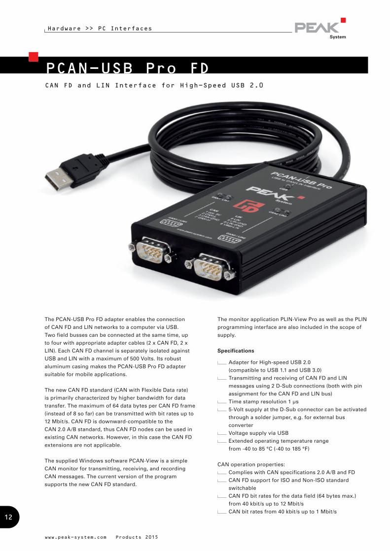
The PCAN-USB Pro FD adapter enables the connection
of CAN FD and LIN networks to a computer via USB.
Two field busses can be connected at the same time, up
to four with appropriate adapter cables (2 x CAN FD, 2 x
LIN). Each CAN FD channel is separately isolated against
USB and LIN with a maximum of 500 Volts. Its robust
aluminum casing makes the PCAN-USB Pro FD adapter
suitable for mobile applications.
The new CAN FD standard (CAN with Flexible Data rate)
is primarily characterized by higher bandwidth for data
transfer. The maximum of 64 data bytes per CAN FD frame
(instead of 8 so far) can be transmitted with bit rates up to
12 Mbit/s. CAN FD is downward-compatible to the
CAN 2.0 A/B standard, thus CAN FD nodes can be used in
existing CAN networks. However, in this case the CAN FD
extensions are not applicable.
The supplied Windows software PCAN-View is a simple
CAN monitor for transmitting, receiving, and recording
CAN messages. The current version of the program
supports the new CAN FD standard.
12
Hardware >> PC Interfaces
www.peak-system.com Products 2015
Designation Part No.
PCAN-USB Pro FD IPEH-004061
Scope of supply
PCAN-USB Pro FD in aluminum casing
CAN FD interface drivers for Windows 8.1, 7, Vista
and Linux (32/64 bit)
LIN interface drivers for Windows 8.1, 7, Vista
(32/64 bit)
PCAN-View CAN monitor for Windows
(details on page 85)
PLIN-View Pro LIN monitor for Windows
(details on page 86)
PCAN-Basic programming interface consisting of
an interface DLL, examples, and header files for
all common programming languages
(details on page 76)
PLIN-API programming interface consisting of an
interface DLL, an example, and header files for all
common programming languages
Manual in PDF format
Please note: The PCAN-USB Pro FD can be used
alternatively for the PCAN-USB Pro, because this CAN
interface is no longer manufactured!
The PCAN-USB Pro FD behaves identically concerning
the CAN and LIN functionality.
Ordering information
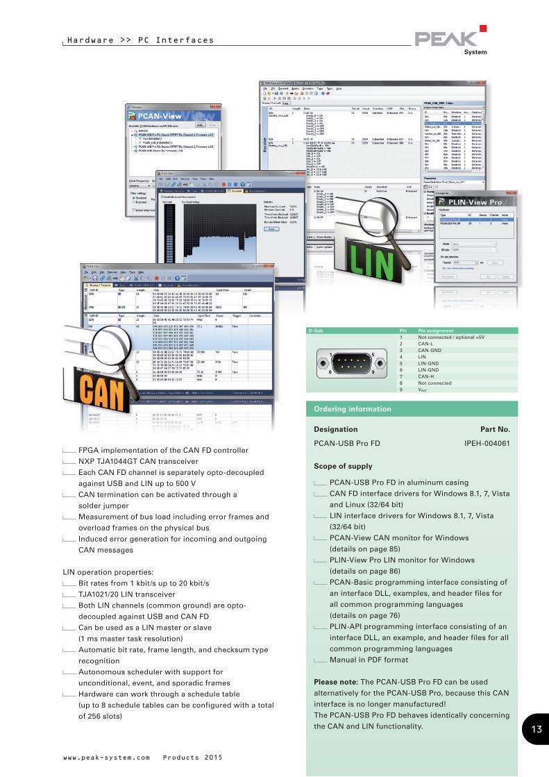
D-Sub Pin Pin assignment1 Not connected / optional +5V2 CAN-L3 CAN-GND4 LIN5 LIN-GND6 LIN-GND7 CAN-H8 Not connected9 VBAT
FPGA implementation of the CAN FD controller
NXP TJA1044GT CAN transceiver
Each CAN FD channel is separately opto-decoupled
against USB and LIN up to 500 V
CAN termination can be activated through a
solder jumper
Measurement of bus load including error frames and
overload frames on the physical bus
Induced error generation for incoming and outgoing
CAN messages
LIN operation properties:
Bit rates from 1 kbit/s up to 20 kbit/s
TJA1021/20 LIN transceiver
Both LIN channels (common ground) are opto-
decoupled against USB and CAN FD
Can be used as a LIN master or slave
(1 ms master task resolution)
Automatic bit rate, frame length, and checksum type
recognition
Autonomous scheduler with support for
unconditional, event, and sporadic frames
Hardware can work through a schedule table
(up to 8 schedule tables can be configured with a total
of 256 slots)
13
PCAN-USB X6
Hardware >> PC Interfaces
www.peak-system.com Products 2015
Specifications
Adapter for High-speed USB 2.0
(compatible to USB 1.1 and USB 3.0)
6 High-speed CAN channels via plugable transceiver
modules. Alternative transceivers for Low-speed CAN
and Single-wire CAN on request
Complies with CAN specifications 2.0 A/B and FD
CAN FD support for ISO and Non-ISO standard
switchable
CAN FD bit rates above 1 Mbit/s for the maximum of
64 bytes of the data field
CAN bit rates from 40 kbit/s up to 1 Mbit/s
Time stamp resolution 1 µs
FPGA implementation of the CAN FD controller
Status LEDs for CAN channels, USB upstream, and
power supply
Connection via D-Sub connectors or M12 circular
connectors
Aluminum casing with increased Ingress Protection
(only for IPEH-004027-M12)
High-speed USB 2.0 downstream port
(only for IPEH-004027)
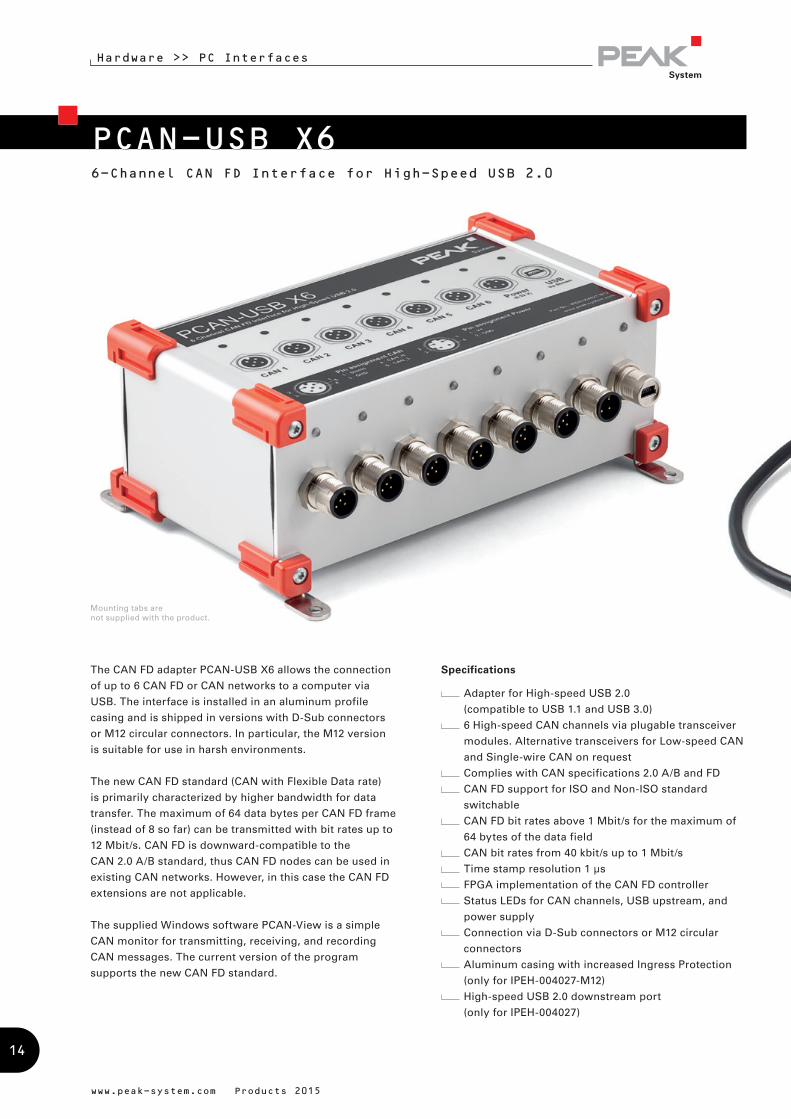
The CAN FD adapter PCAN-USB X6 allows the connection
of up to 6 CAN FD or CAN networks to a computer via
USB. The interface is installed in an aluminum profile
casing and is shipped in versions with D-Sub connectors
or M12 circular connectors. In particular, the M12 version
is suitable for use in harsh environments.
The new CAN FD standard (CAN with Flexible Data rate)
is primarily characterized by higher bandwidth for data
transfer. The maximum of 64 data bytes per CAN FD frame
(instead of 8 so far) can be transmitted with bit rates up to
12 Mbit/s. CAN FD is downward-compatible to the
CAN 2.0 A/B standard, thus CAN FD nodes can be used in
existing CAN networks. However, in this case the CAN FD
extensions are not applicable.
The supplied Windows software PCAN-View is a simple
CAN monitor for transmitting, receiving, and recording
CAN messages. The current version of the program
supports the new CAN FD standard.
6-Channel CAN FD Interface for High-Speed USB 2.0
Mounting tabs are not supplied with the product.
14

Hardware >> PC Interfaces
www.peak-system.com Products 2015
CAN termination switchable, separately for each CAN
channel (transceiver-dependent)
Measurement of bus load including error frames and
overload frames on the physical bus
Induced error generation for incoming and outgoing
CAN messages
Voltage supply from 9 to 32 V
Extended operating temperature range
from -40 to 85 °C (-40 to 185 °F)
Designation Part No.
PCAN-USB X6 IPEH-004027
PCAN-USB X6 with M12 circular connectors IPEH-004027-M12
Scope of supply
PCAN-USB X6 in aluminum casing
IPEH-004027: Mating connector for power supply
Device drivers for Windows 8.1, 7, Vista and Linux
(32/64-bit)
PCAN-View CAN monitor for Windows
(details on page 85)
PCAN-Basic programming interface consisting of
an interface DLL, examples, and header files for
all common programming languages
(details on page 76)
Manual in PDF format
Note: Expected to be available in Q4 2015
Ordering information
15
PCAN-USBCAN Interface for USB
Hardware >> PC Interfaces
www.peak-system.com Products 2015
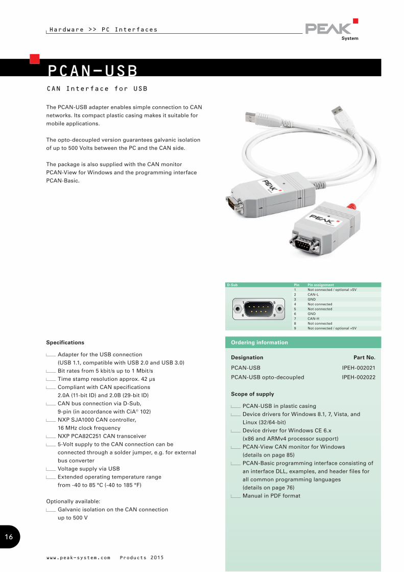
The PCAN-USB adapter enables simple connection to CAN
networks. Its compact plastic casing makes it suitable for
mobile applications.
The opto-decoupled version guarantees galvanic isolation
of up to 500 Volts between the PC and the CAN side.
The package is also supplied with the CAN monitor
PCAN-View for Windows and the programming interface
PCAN-Basic.
Specifications
Adapter for the USB connection
(USB 1.1, compatible with USB 2.0 and USB 3.0)
Bit rates from 5 kbit/s up to 1 Mbit/s
Time stamp resolution approx. 42 µs
Compliant with CAN specifications
2.0A (11-bit ID) and 2.0B (29-bit ID)
CAN bus connection via D-Sub,
9-pin (in accordance with CiA® 102)
NXP SJA1000 CAN controller,
16 MHz clock frequency
NXP PCA82C251 CAN transceiver
5-Volt supply to the CAN connection can be
connected through a solder jumper, e.g. for external
bus converter
Voltage supply via USB
Extended operating temperature range
from -40 to 85 °C (-40 to 185 °F)
Optionally available:
Galvanic isolation on the CAN connection
up to 500 V
Designation Part No.
PCAN-USB IPEH-002021
PCAN-USB opto-decoupled IPEH-002022
Scope of supply
PCAN-USB in plastic casing
Device drivers for Windows 8.1, 7, Vista, and
Linux (32/64-bit)
Device driver for Windows CE 6.x
(x86 and ARMv4 processor support)
PCAN-View CAN monitor for Windows
(details on page 85)
PCAN-Basic programming interface consisting of
an interface DLL, examples, and header files for
all common programming languages
(details on page 76)
Manual in PDF format
Ordering information
D-Sub Pin Pin assignment1 Not connected / optional +5V2 CAN-L3 GND4 Not connected5 Not connected6 GND7 CAN-H8 Not connected9 Not connected / optional +5V
16
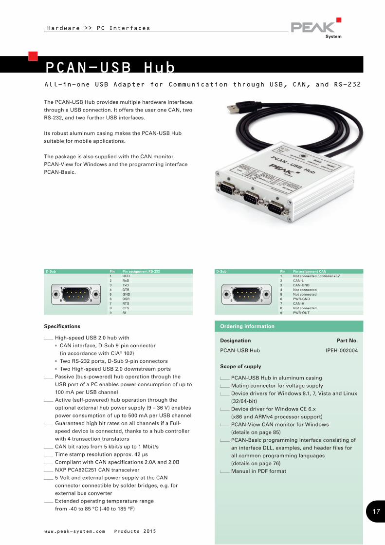
PCAN-USB HubAll-in-one USB Adapter for Communication through USB, CAN, and RS-232
Hardware >> PC Interfaces
The PCAN-USB Hub provides multiple hardware interfaces
through a USB connection. It offers the user one CAN, two
RS-232, and two further USB interfaces.
Its robust aluminum casing makes the PCAN-USB Hub
suitable for mobile applications.
The package is also supplied with the CAN monitor
PCAN-View for Windows and the programming interface
PCAN-Basic.
www.peak-system.com Products 2015
Specifications
High-speed USB 2.0 hub with
CAN interface, D-Sub 9-pin connector
(in accordance with CiA® 102)
Two RS-232 ports, D-Sub 9-pin connectors
Two High-speed USB 2.0 downstream ports
Passive (bus-powered) hub operation through the
USB port of a PC enables power consumption of up to
100 mA per USB channel
Active (self-powered) hub operation through the
optional external hub power supply (9 – 36 V) enables
power consumption of up to 500 mA per USB channel
Guaranteed high bit rates on all channels if a Full-
speed device is connected, thanks to a hub controller
with 4 transaction translators
CAN bit rates from 5 kbit/s up to 1 Mbit/s
Time stamp resolution approx. 42 µs
Compliant with CAN specifications 2.0A and 2.0B
NXP PCA82C251 CAN transceiver
5-Volt and external power supply at the CAN
connector connectible by solder bridges, e.g. for
external bus converter
Extended operating temperature range
from -40 to 85 °C (-40 to 185 °F)
Designation Part No.
PCAN-USB Hub IPEH-002004
Scope of supply
PCAN-USB Hub in aluminum casing
Mating connector for voltage supply
Device drivers for Windows 8.1, 7, Vista and Linux
(32/64-bit)
Device driver for Windows CE 6.x
(x86 and ARMv4 processor support)
PCAN-View CAN monitor for Windows
(details on page 85)
PCAN-Basic programming interface consisting of
an interface DLL, examples, and header files for
all common programming languages
(details on page 76)
Manual in PDF format
Ordering information
D-Sub Pin Pin assignment RS-2321 DCD2 RxD3 TxD4 DTR5 GND6 DSR7 RTS8 CTS9 RI
D-Sub Pin Pin assignment CAN1 Not connected / optional +5V2 CAN-L3 CAN-GND4 Not connected5 Not connected6 PWR-GND7 CAN-H8 Not connected9 PWR-OUT
17

PCAN-PCI
Hardware >> PC Interfaces
CAN Interface for PCI
The PCAN-PCI card enables the connection of a PC with
PCI slots to CAN networks.
The card is available as a single or dual-channel version.
The opto-decoupled versions also guarantee galvanic
isolation of up to 500 Volts between the PC and the CAN
sides.
The package is also supplied with the CAN monitor
PCAN-View for Windows and the programming interface
PCAN-Basic.
www.peak-system.com Products 2015
Designation Part No.
PCAN-PCI Single Channel IPEH-002064
PCAN-PCI Dual Channel IPEH-002065
PCAN-PCI Single Channel opto-decoupled IPEH-002066
PCAN-PCI Dual Channel opto-decoupled IPEH-002067
Scope of supply
PCAN-PCI card
Device drivers for Windows 8.1, 7, Vista and Linux
(32/64-bit)
Device driver for Windows CE 6.x
(x86 and ARMv4 processor support)
PCAN-View CAN monitor for Windows
(details on page 85)
PCAN-Basic programming interface consisting of
an interface DLL, examples, and header files for
all common programming languages
(details on page 76)
Manual in PDF format
Ordering information
D-Sub Pin Pin assignment 1 Not connected / optional +5V2 CAN-L3 GND4 Not connected5 Not connected6 GND7 CAN-H8 Not connected9 Not connected / optional +5V
Specifications
PC plug-in card for PCI slots
Bit rates from 5 kbit/s up to 1 Mbit/s
Compliant with CAN specifications
2.0A (11-bit ID) and 2.0B (29-bit ID)
CAN bus connection via D-Sub,
9-pin (in accordance with CiA® 102)
NXP SJA1000 CAN controller, 16 MHz clock frequency
NXP PCA82C251 CAN transceiver
5-Volt supply to the CAN connection can be
connected through a solder jumper, e.g. for external
bus converter
Extended operating temperature range
from -40 to 85 °C (-40 to 185 °F)
Optionally available:
Single-channel or dual-channel version
Galvanic isolation on the CAN connection up to 500 V,
separate for each CAN channel
18
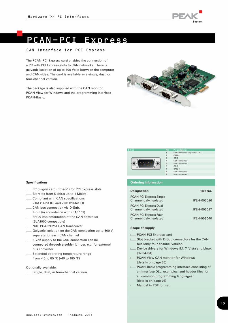
CAN Interface for PCI Express
The PCAN-PCI Express card enables the connection of
a PC with PCI Express slots to CAN networks. There is
galvanic isolation of up to 500 Volts between the computer
and CAN sides. The card is available as a single, dual, or
four-channel version.
The package is also supplied with the CAN monitor
PCAN-View for Windows and the programming interface
PCAN-Basic.
Specifications
PC plug-in card (PCIe-x1) for PCI Express slots
Bit rates from 5 kbit/s up to 1 Mbit/s
Compliant with CAN specifications
2.0A (11-bit ID) and 2.0B (29-bit ID)
CAN bus connection via D-Sub,
9-pin (in accordance with CiA® 102)
FPGA implementation of the CAN controller
(SJA1000 compatible)
NXP PCA82C251 CAN transceiver
Galvanic isolation on the CAN connection up to 500 V,
separate for each CAN channel
5-Volt supply to the CAN connection can be
connected through a solder jumper, e.g. for external
bus converter
Extended operating temperature range
from -40 to 85 °C (-40 to 185 °F)
Optionally available:
Single, dual, or four-channel version
www.peak-system.com Products 2015
PCAN-PCI Express
Hardware >> PC Interfaces
Designation Part No.
PCAN-PCI Express Single Channel galv. isolated IPEH-003026
PCAN-PCI Express Dual Channel galv. isolated IPEH-003027
PCAN-PCI Express Four Channel galv. isolated IPEH-003040
Scope of supply
PCAN-PCI Express card
Slot bracket with D-Sub connectors for the CAN
bus (only four-channel version)
Device drivers for Windows 8.1, 7, Vista and Linux
(32/64-bit)
PCAN-View CAN monitor for Windows
(details on page 85)
PCAN-Basic programming interface consisting of
an interface DLL, examples, and header files for
all common programming languages
(details on page 76)
Manual in PDF format
Ordering information
D-Sub Pin Pin assignment 1 Not connected / optional +5V2 CAN-L3 GND4 Not connected5 Not connected6 GND7 CAN-H8 Not connected9 Not connected
19
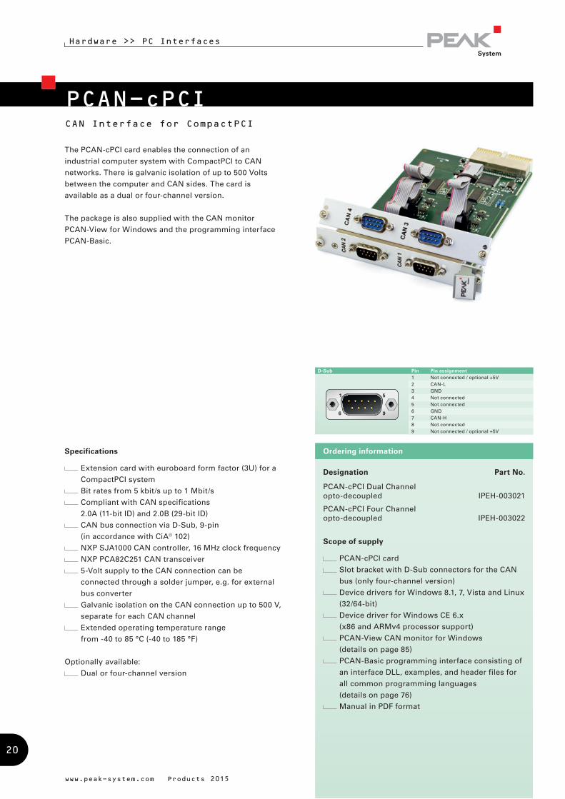
PCAN-cPCICAN Interface for CompactPCI
Hardware >> PC Interfaces
The PCAN-cPCI card enables the connection of an
industrial computer system with CompactPCI to CAN
networks. There is galvanic isolation of up to 500 Volts
between the computer and CAN sides. The card is
available as a dual or four-channel version.
The package is also supplied with the CAN monitor
PCAN-View for Windows and the programming interface
PCAN-Basic.
Specifications
Extension card with euroboard form factor (3U) for a
CompactPCI system
Bit rates from 5 kbit/s up to 1 Mbit/s
Compliant with CAN specifications
2.0A (11-bit ID) and 2.0B (29-bit ID)
CAN bus connection via D-Sub, 9-pin
(in accordance with CiA® 102)
NXP SJA1000 CAN controller, 16 MHz clock frequency
NXP PCA82C251 CAN transceiver
5-Volt supply to the CAN connection can be
connected through a solder jumper, e.g. for external
bus converter
Galvanic isolation on the CAN connection up to 500 V,
separate for each CAN channel
Extended operating temperature range
from -40 to 85 °C (-40 to 185 °F)
Optionally available:
Dual or four-channel version
www.peak-system.com Products 2015
Designation Part No.
PCAN-cPCI Dual Channel opto-decoupled IPEH-003021
PCAN-cPCI Four Channel opto-decoupled IPEH-003022
Scope of supply
PCAN-cPCI card
Slot bracket with D-Sub connectors for the CAN
bus (only four-channel version)
Device drivers for Windows 8.1, 7, Vista and Linux
(32/64-bit)
Device driver for Windows CE 6.x
(x86 and ARMv4 processor support)
PCAN-View CAN monitor for Windows
(details on page 85)
PCAN-Basic programming interface consisting of
an interface DLL, examples, and header files for
all common programming languages
(details on page 76)
Manual in PDF format
Ordering information
D-Sub Pin Pin assignment1 Not connected / optional +5V2 CAN-L3 GND4 Not connected5 Not connected6 GND7 CAN-H8 Not connected9 Not connected / optional +5V
20

Hardware >> PC Interfaces
PCAN-miniPCICAN Interface for Mini PCI
The PCAN-miniPCI card enables the connection of
embedded PCs and laptops with Mini PCI slots to CAN
networks.
The card is available as a single or dual-channel version.
The opto-decoupled versions also guarantee galvanic
isolation of up to 300 Volts between the PC and the CAN
sides.
The package is also supplied with the CAN monitor
PCAN-View for Windows and the programming interface
PCAN-Basic.
Designation Part No.
PCAN-miniPCI Dual Ch. IPEH-003045
PCAN-miniPCI Single Ch. opto-decoupled IPEH-003046
PCAN-miniPCI Dual Ch. opto-decoupled IPEH-003047
Scope of supply
PCAN-miniPCI card
Connection cable including D-Sub plug for each
channel
Device drivers for Windows 8.1, 7, Vista and Linux
(32/64-bit)
Device driver for Windows CE 6.x
(x86 and ARMv4 processor support)
PCAN-View CAN monitor for Windows
(details on page 85)
PCAN-Basic programming interface consisting of
an interface DLL, examples, and header files for
all common programming languages
(details on page 76)
Manual in PDF format
Ordering informationSpecifications
CAN interface for the Mini PCI slot
CAN bus connection via connection cable and D-Sub,
9-pin (in accordance with CiA® 102)
Bit rates from 40 kbit/s up to 1 Mbit/s
Compliant with CAN specifications
2.0A (11-bit ID) and 2.0B (29-bit ID)
NXP SJA1000 CAN controller, 16 MHz clock frequency
NXP TJA1040 CAN transceiver
Space-saving dimensions thanks to SMD technology
5-Volt supply to the CAN connection can be
connected through a solder jumper, e.g. for external
bus converter
Operating temperature range
from 0 to 70 °C (32 to 158 °F)
Optionally available:
Single-channel or dual-channel version
Galvanic isolation on the CAN connection up to 300 V,
separate for each CAN channel
www.peak-system.com Products 2015
D-Sub Pin Pin assignment1 Not connected / optional +5V2 CAN-L3 GND4 Not connected5 Not connected6 GND7 CAN-H8 Not connected9 Not connected
21
Hardware >> PC Interfaces
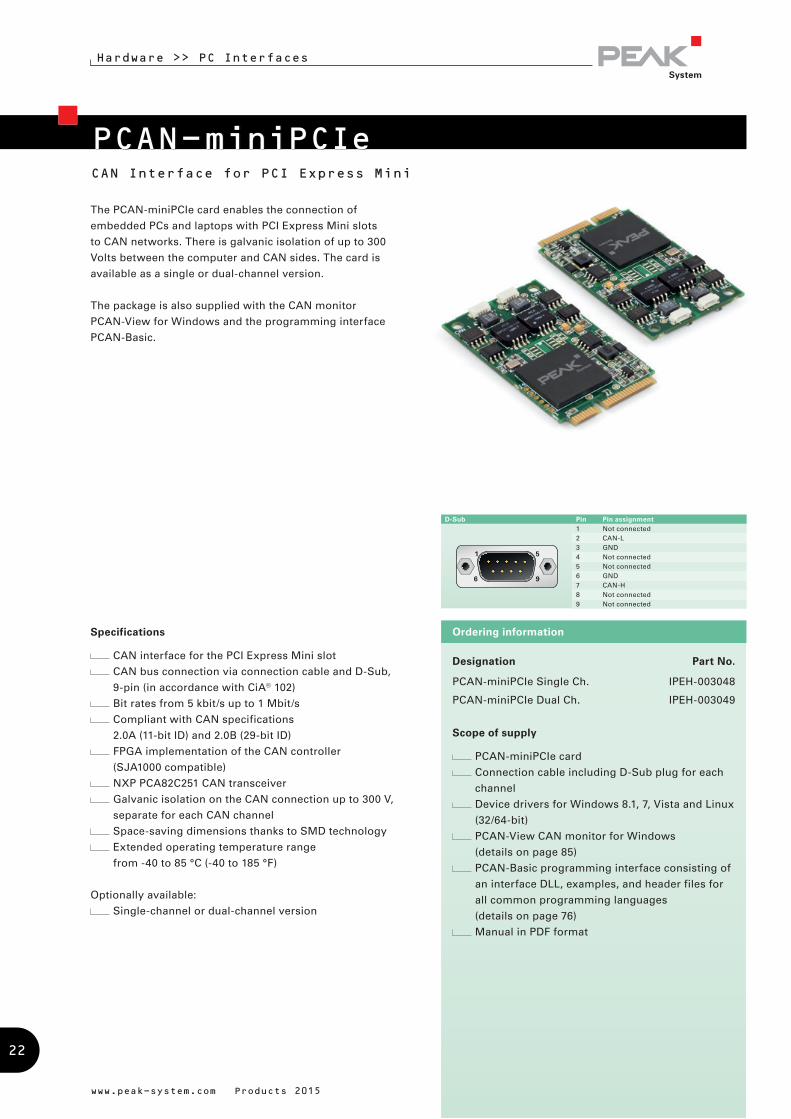
PCAN-miniPCIeCAN Interface for PCI Express Mini
The PCAN-miniPCIe card enables the connection of
embedded PCs and laptops with PCI Express Mini slots
to CAN networks. There is galvanic isolation of up to 300
Volts between the computer and CAN sides. The card is
available as a single or dual-channel version.
The package is also supplied with the CAN monitor
PCAN-View for Windows and the programming interface
PCAN-Basic.
Designation Part No.
PCAN-miniPCIe Single Ch. IPEH-003048
PCAN-miniPCIe Dual Ch. IPEH-003049
Scope of supply
PCAN-miniPCIe card
Connection cable including D-Sub plug for each
channel
Device drivers for Windows 8.1, 7, Vista and Linux
(32/64-bit)
PCAN-View CAN monitor for Windows
(details on page 85)
PCAN-Basic programming interface consisting of
an interface DLL, examples, and header files for
all common programming languages
(details on page 76)
Manual in PDF format
Ordering informationSpecifications
CAN interface for the PCI Express Mini slot
CAN bus connection via connection cable and D-Sub,
9-pin (in accordance with CiA® 102)
Bit rates from 5 kbit/s up to 1 Mbit/s
Compliant with CAN specifications
2.0A (11-bit ID) and 2.0B (29-bit ID)
FPGA implementation of the CAN controller
(SJA1000 compatible)
NXP PCA82C251 CAN transceiver
Galvanic isolation on the CAN connection up to 300 V,
separate for each CAN channel
Space-saving dimensions thanks to SMD technology
Extended operating temperature range
from -40 to 85 °C (-40 to 185 °F)
Optionally available:
Single-channel or dual-channel version
www.peak-system.com Products 2015
D-Sub Pin Pin assignment1 Not connected2 CAN-L3 GND4 Not connected5 Not connected6 GND7 CAN-H8 Not connected9 Not connected
22
PCAN-PC/104
Hardware >> PC Interfaces
CAN Interface for PC/104
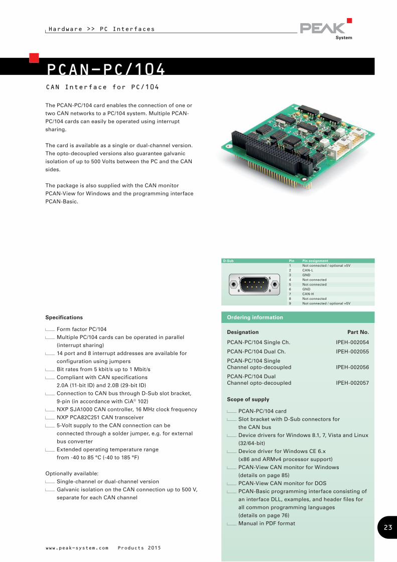
The PCAN-PC/104 card enables the connection of one or
two CAN networks to a PC/104 system. Multiple PCAN-
PC/104 cards can easily be operated using interrupt
sharing.
The card is available as a single or dual-channel version.
The opto-decoupled versions also guarantee galvanic
isolation of up to 500 Volts between the PC and the CAN
sides.
The package is also supplied with the CAN monitor
PCAN-View for Windows and the programming interface
PCAN-Basic.
www.peak-system.com Products 2015
Specifications
Form factor PC/104
Multiple PC/104 cards can be operated in parallel
(interrupt sharing)
14 port and 8 interrupt addresses are available for
configuration using jumpers
Bit rates from 5 kbit/s up to 1 Mbit/s
Compliant with CAN specifications
2.0A (11-bit ID) and 2.0B (29-bit ID)
Connection to CAN bus through D-Sub slot bracket,
9-pin (in accordance with CiA® 102)
NXP SJA1000 CAN controller, 16 MHz clock frequency
NXP PCA82C251 CAN transceiver
5-Volt supply to the CAN connection can be
connected through a solder jumper, e.g. for external
bus converter
Extended operating temperature range
from -40 to 85 °C (-40 to 185 °F)
Optionally available:
Single-channel or dual-channel version
Galvanic isolation on the CAN connection up to 500 V,
separate for each CAN channel
Designation Part No.
PCAN-PC/104 Single Ch. IPEH-002054
PCAN-PC/104 Dual Ch. IPEH-002055
PCAN-PC/104 Single Channel opto-decoupled IPEH-002056
PCAN-PC/104 Dual Channel opto-decoupled IPEH-002057
Scope of supply
PCAN-PC/104 card
Slot bracket with D-Sub connectors for
the CAN bus
Device drivers for Windows 8.1, 7, Vista and Linux
(32/64-bit)
Device driver for Windows CE 6.x
(x86 and ARMv4 processor support)
PCAN-View CAN monitor for Windows
(details on page 85)
PCAN-View CAN monitor for DOS
PCAN-Basic programming interface consisting of
an interface DLL, examples, and header files for
all common programming languages
(details on page 76)
Manual in PDF format
Ordering information
D-Sub Pin Pin assignment 1 Not connected / optional +5V2 CAN-L3 GND4 Not connected5 Not connected6 GND7 CAN-H8 Not connected9 Not connected / optional +5V
23
PCAN-PC/104-PlusCAN Interface for PC/104-Plus
Hardware >> PC Interfaces
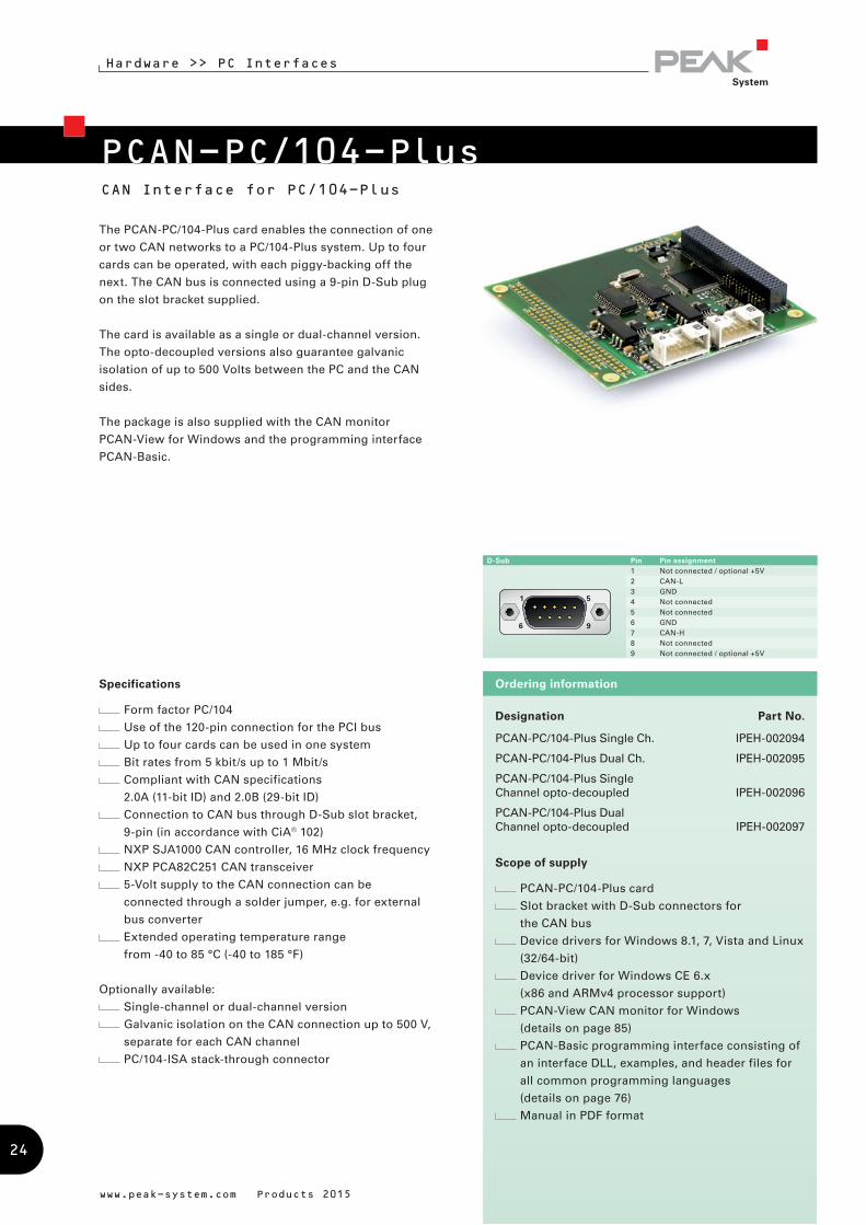
The PCAN-PC/104-Plus card enables the connection of one
or two CAN networks to a PC/104-Plus system. Up to four
cards can be operated, with each piggy-backing off the
next. The CAN bus is connected using a 9-pin D-Sub plug
on the slot bracket supplied.
The card is available as a single or dual-channel version.
The opto-decoupled versions also guarantee galvanic
isolation of up to 500 Volts between the PC and the CAN
sides.
The package is also supplied with the CAN monitor
PCAN-View for Windows and the programming interface
PCAN-Basic.
www.peak-system.com Products 2015
Designation Part No.
PCAN-PC/104-Plus Single Ch. IPEH-002094
PCAN-PC/104-Plus Dual Ch. IPEH-002095
PCAN-PC/104-Plus Single Channel opto-decoupled IPEH-002096
PCAN-PC/104-Plus Dual Channel opto-decoupled IPEH-002097
Scope of supply
PCAN-PC/104-Plus card
Slot bracket with D-Sub connectors for
the CAN bus
Device drivers for Windows 8.1, 7, Vista and Linux
(32/64-bit)
Device driver for Windows CE 6.x
(x86 and ARMv4 processor support)
PCAN-View CAN monitor for Windows
(details on page 85)
PCAN-Basic programming interface consisting of
an interface DLL, examples, and header files for
all common programming languages
(details on page 76)
Manual in PDF format
Ordering informationSpecifications
Form factor PC/104
Use of the 120-pin connection for the PCI bus
Up to four cards can be used in one system
Bit rates from 5 kbit/s up to 1 Mbit/s
Compliant with CAN specifications
2.0A (11-bit ID) and 2.0B (29-bit ID)
Connection to CAN bus through D-Sub slot bracket,
9-pin (in accordance with CiA® 102)
NXP SJA1000 CAN controller, 16 MHz clock frequency
NXP PCA82C251 CAN transceiver
5-Volt supply to the CAN connection can be
connected through a solder jumper, e.g. for external
bus converter
Extended operating temperature range
from -40 to 85 °C (-40 to 185 °F)
Optionally available:
Single-channel or dual-channel version
Galvanic isolation on the CAN connection up to 500 V,
separate for each CAN channel
PC/104-ISA stack-through connector
D-Sub Pin Pin assignment1 Not connected / optional +5V2 CAN-L3 GND4 Not connected5 Not connected6 GND7 CAN-H8 Not connected9 Not connected / optional +5V
24

PCAN-PC/104-Plus QuadFour-Channel CAN Interface for PC/104-Plus
Hardware >> PC Interfaces
Designation Part No.
PCAN-PC/104-Plus Quad IPEH-002099
Scope of supply
PCAN-PC/104-Plus Quad card
Two slot brackets with D-Sub connectors for
the CAN bus
Device drivers for Windows 8.1, 7, Vista and Linux
(32/64-bit)
PCAN-View CAN monitor for Windows
(details on page 85)
PCAN-Basic programming interface consisting of
an interface DLL, examples, and header files for
all common programming languages
(details on page 76)
Manual in PDF format
Ordering information
The PCAN-PC/104-Plus Quad card enables the connection
of four CAN networks to a PC/104-Plus system. Up to four
cards can be operated, with each piggy-backing off the
next. The CAN bus is connected using a 9-pin D-Sub plug
on the slot brackets supplied. There is galvanic isolation of
up to 500 Volts between the computer and CAN sides.
The package is also supplied with the CAN monitor
PCAN-View for Windows and the programming interface
PCAN-Basic.
Specifications
Form factor PC/104
Use of the 120-pin connection for the PCI bus
Up to four cards can be used in one system
Bit rates from 5 kbit/s up to 1 Mbit/s
Compliant with CAN specifications
2.0A (11-bit ID) and 2.0B (29-bit ID)
Connection to CAN bus through D-Sub slot brackets,
9-pin (in accordance with CiA® 102)
FPGA implementation of the CAN controller
(SJA1000 compatible)
NXP PCA82C251 CAN transceiver
Galvanic isolation on the CAN connection up to 500 V,
separate for each CAN channel
5-Volt supply to the CAN connection can be connected
through a solder jumper, e.g. for external bus
converter
Extended operating temperature range
from -40 to 85 °C (-40 to 185 °F)
Optionally available:
PC/104-ISA stack-through connector
www.peak-system.com Products 2015
D-Sub Pin Pin assignment1 Not connected / optional +5V2 CAN-L3 GND4 Not connected5 Not connected6 GND7 CAN-H8 Not connected9 Not connected / optional +5V
25
Hardware >> PC Interfaces
CAN Interface for PCI/104-Express
PCAN-PCI/104-Express
Designation Part No.
PCAN-PCI/104-Express Single Ch. opto-decoupled IPEH-003056
PCAN-PCI/104-Express Dual Ch. opto-decoupled IPEH-003057
PCAN-PCI/104-Express Quad IPEH-003058
Scope of supply
PCAN-PCI/104-Express card
Slot bracket with D-Sub connector(s) for
the CAN bus (two for the four-channel version)
Device drivers for Windows 8.1, 7, Vista and Linux
(32/64-bit)
PCAN-View CAN monitor for Windows
(details on page 85)
PCAN-Basic programming interface consisting of
an interface DLL, examples, and header files for
all common programming languages
(details on page 76)
Manual in PDF format
Ordering information
www.peak-system.com Products 2015
D-Sub Pin Pin assignment1 Not connected2 CAN-L3 GND4 Not connected5 Not connected6 GND7 CAN-H8 Not connected9 Not connected / optional +5V
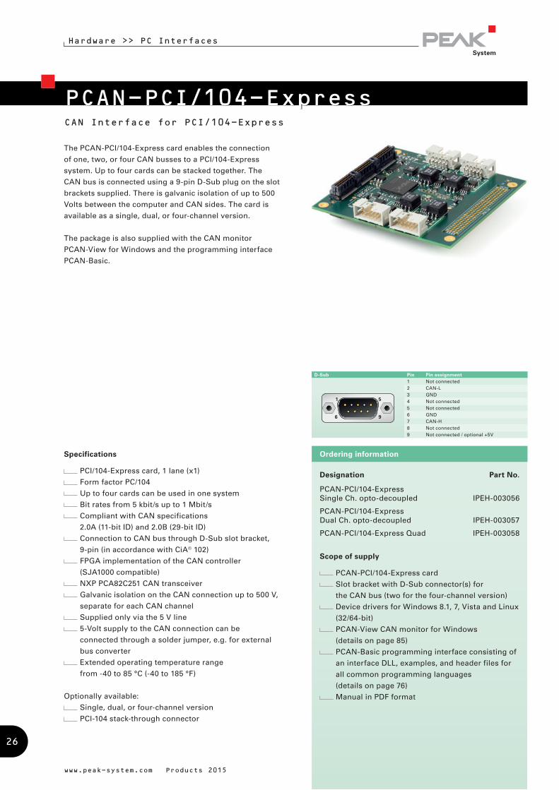
The PCAN-PCI/104-Express card enables the connection
of one, two, or four CAN busses to a PCI/104-Express
system. Up to four cards can be stacked together. The
CAN bus is connected using a 9-pin D-Sub plug on the slot
brackets supplied. There is galvanic isolation of up to 500
Volts between the computer and CAN sides. The card is
available as a single, dual, or four-channel version.
The package is also supplied with the CAN monitor
PCAN-View for Windows and the programming interface
PCAN-Basic.
Specifications
PCI/104-Express card, 1 lane (x1)
Form factor PC/104
Up to four cards can be used in one system
Bit rates from 5 kbit/s up to 1 Mbit/s
Compliant with CAN specifications
2.0A (11-bit ID) and 2.0B (29-bit ID)
Connection to CAN bus through D-Sub slot bracket,
9-pin (in accordance with CiA® 102)
FPGA implementation of the CAN controller
(SJA1000 compatible)
NXP PCA82C251 CAN transceiver
Galvanic isolation on the CAN connection up to 500 V,
separate for each CAN channel
Supplied only via the 5 V line
5-Volt supply to the CAN connection can be
connected through a solder jumper, e.g. for external
bus converter
Extended operating temperature range
from -40 to 85 °C (-40 to 185 °F)
Optionally available:
Single, dual, or four-channel version
PCI-104 stack-through connector
26
Specifications
Card for the ExpressCard slot
Type ExpressCard/34 (compatible with
ExpressCard/54 slots)
Bit rates from 5 kbit/s up to 1 Mbit/s
Compliant with CAN specifications
2.0A (11-bit ID) and 2.0B (29-bit ID)
CAN bus connection via D-Sub,
9-pin (in accordance with CiA® 102)
FPGA implementation of the CAN controller
(SJA1000 compatible)
NXP PCA82C251 CAN transceiver
Galvanic isolation on the CAN connection up to 300 V
Extended operating temperature range
from -40 to 85 °C (-40 to 185 °F)
Hardware >> PC Interfaces
www.peak-system.com Products 2015
PCAN-ExpressCard 34CAN Interface for the ExpressCard/34 Slot
Ordering information
Designation Part No.
PCAN-ExpressCard 34 IPEH-003004
Scope of supply
PCAN-ExpressCard 34 CAN interface
Device drivers for Windows 8.1, 7, Vista and Linux
(32/64-bit)
PCAN-View CAN monitor for Windows
(details on page 85)
PCAN-Basic programming interface consisting of
an interface DLL, examples, and header files for
all common programming languages
(details on page 76)
Manual in PDF format
D-Sub Pin Pin assignment1 Not connected2 CAN-L3 GND4 Not connected5 Not connected6 GND7 CAN-H8 Not connected9 Not connected
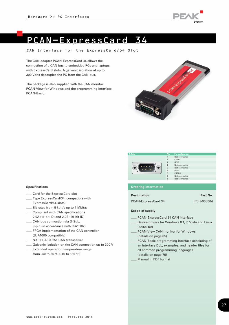
The CAN adapter PCAN-ExpressCard 34 allows the
connection of a CAN bus to embedded PCs and laptops
with ExpressCard slots. A galvanic isolation of up to
300 Volts decouples the PC from the CAN bus.
The package is also supplied with the CAN monitor
PCAN-View for Windows and the programming interface
PCAN-Basic.
27
Hardware >> PC Interfaces
www.peak-system.com Products 2015
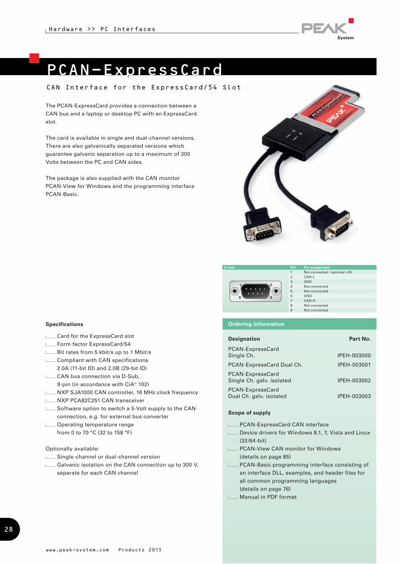
PCAN-ExpressCardCAN Interface for the ExpressCard/54 Slot
The PCAN-ExpressCard provides a connection between a
CAN bus and a laptop or desktop PC with an ExpressCard
slot.
The card is available in single and dual-channel versions.
There are also galvanically separated versions which
guarantee galvanic separation up to a maximum of 300
Volts between the PC and CAN sides.
The package is also supplied with the CAN monitor
PCAN-View for Windows and the programming interface
PCAN-Basic.
Specifications
Card for the ExpressCard slot
Form factor ExpressCard/54
Bit rates from 5 kbit/s up to 1 Mbit/s
Compliant with CAN specifications
2.0A (11-bit ID) and 2.0B (29-bit ID)
CAN bus connection via D-Sub,
9-pin (in accordance with CiA® 102)
NXP SJA1000 CAN controller, 16 MHz clock frequency
NXP PCA82C251 CAN transceiver
Software option to switch a 5-Volt supply to the CAN
connection, e.g. for external bus converter
Operating temperature range
from 0 to 70 °C (32 to 158 °F)
Optionally available:
Single-channel or dual-channel version
Galvanic isolation on the CAN connection up to 300 V,
separate for each CAN channel
Ordering information
Designation Part No.
PCAN-ExpressCard Single Ch. IPEH-003000
PCAN-ExpressCard Dual Ch. IPEH-003001
PCAN-ExpressCard Single Ch. galv. isolated IPEH-003002
PCAN-ExpressCard Dual Ch. galv. isolated IPEH-003003
Scope of supply
PCAN-ExpressCard CAN interface
Device drivers for Windows 8.1, 7, Vista and Linux
(32/64-bit)
PCAN-View CAN monitor for Windows
(details on page 85)
PCAN-Basic programming interface consisting of
an interface DLL, examples, and header files for
all common programming languages
(details on page 76)
Manual in PDF format
D-Sub Pin Pin assignment1 Not connected / optional +5V2 CAN-L3 GND4 Not connected5 Not connected6 GND7 CAN-H8 Not connected9 Not connected
28
Hardware >> PC Interfaces
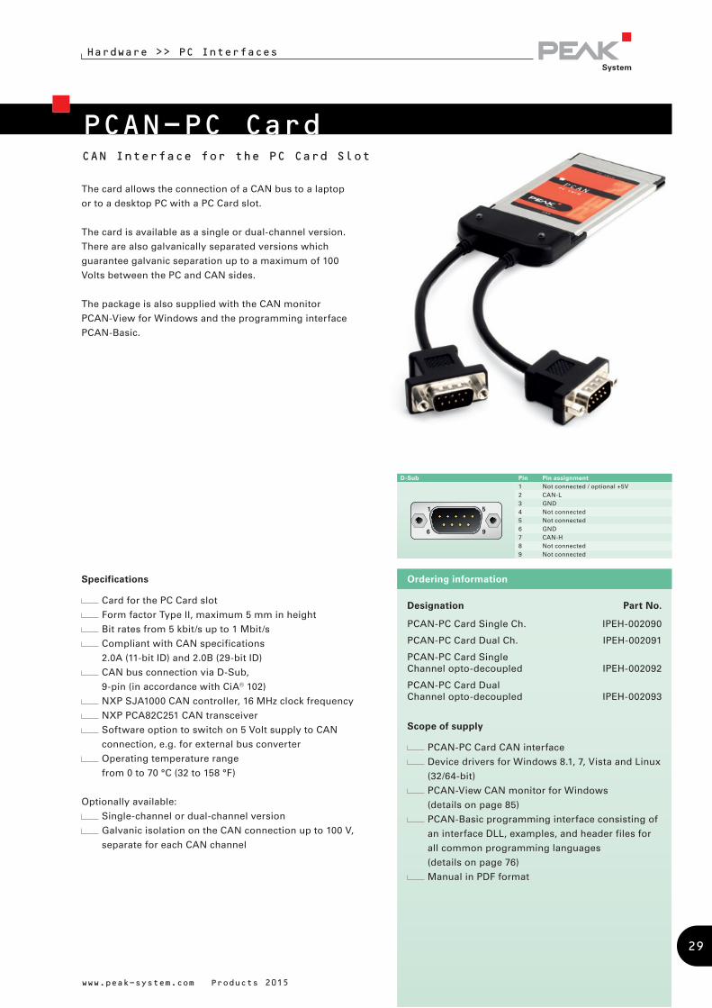
PCAN-PC CardCAN Interface for the PC Card Slot
The card allows the connection of a CAN bus to a laptop
or to a desktop PC with a PC Card slot.
The card is available as a single or dual-channel version.
There are also galvanically separated versions which
guarantee galvanic separation up to a maximum of 100
Volts between the PC and CAN sides.
The package is also supplied with the CAN monitor
PCAN-View for Windows and the programming interface
PCAN-Basic.
www.peak-system.com Products 2015
Designation Part No.
PCAN-PC Card Single Ch. IPEH-002090
PCAN-PC Card Dual Ch. IPEH-002091
PCAN-PC Card Single Channel opto-decoupled IPEH-002092
PCAN-PC Card Dual Channel opto-decoupled IPEH-002093
Scope of supply
PCAN-PC Card CAN interface
Device drivers for Windows 8.1, 7, Vista and Linux
(32/64-bit)
PCAN-View CAN monitor for Windows
(details on page 85)
PCAN-Basic programming interface consisting of
an interface DLL, examples, and header files for
all common programming languages
(details on page 76)
Manual in PDF format
Ordering informationSpecifications
Card for the PC Card slot
Form factor Type II, maximum 5 mm in height
Bit rates from 5 kbit/s up to 1 Mbit/s
Compliant with CAN specifications
2.0A (11-bit ID) and 2.0B (29-bit ID)
CAN bus connection via D-Sub,
9-pin (in accordance with CiA® 102)
NXP SJA1000 CAN controller, 16 MHz clock frequency
NXP PCA82C251 CAN transceiver
Software option to switch on 5 Volt supply to CAN
connection, e.g. for external bus converter
Operating temperature range
from 0 to 70 °C (32 to 158 °F)
Optionally available:
Single-channel or dual-channel version
Galvanic isolation on the CAN connection up to 100 V,
separate for each CAN channel
D-Sub Pin Pin assignment 1 Not connected / optional +5V2 CAN-L3 GND4 Not connected5 Not connected6 GND7 CAN-H8 Not connected9 Not connected
29
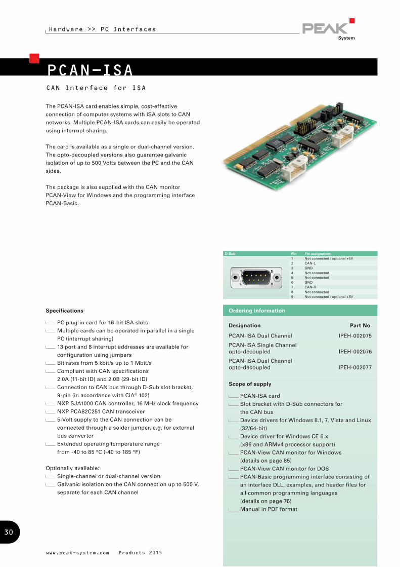
PCAN-ISACAN Interface for ISA
Hardware >> PC Interfaces
Designation Part No.
PCAN-ISA Dual Channel IPEH-002075
PCAN-ISA Single Channel opto-decoupled IPEH-002076
PCAN-ISA Dual Channel opto-decoupled IPEH-002077
Scope of supply
PCAN-ISA card
Slot bracket with D-Sub connectors for
the CAN bus
Device drivers for Windows 8.1, 7, Vista and Linux
(32/64-bit)
Device driver for Windows CE 6.x
(x86 and ARMv4 processor support)
PCAN-View CAN monitor for Windows
(details on page 85)
PCAN-View CAN monitor for DOS
PCAN-Basic programming interface consisting of
an interface DLL, examples, and header files for
all common programming languages
(details on page 76)
Manual in PDF format
Ordering information
The PCAN-ISA card enables simple, cost-effective
connection of computer systems with ISA slots to CAN
networks. Multiple PCAN-ISA cards can easily be operated
using interrupt sharing.
The card is available as a single or dual-channel version.
The opto-decoupled versions also guarantee galvanic
isolation of up to 500 Volts between the PC and the CAN
sides.
The package is also supplied with the CAN monitor
PCAN-View for Windows and the programming interface
PCAN-Basic.
Specifications
PC plug-in card for 16-bit ISA slots
Multiple cards can be operated in parallel in a single
PC (interrupt sharing)
13 port and 8 interrupt addresses are available for
configuration using jumpers
Bit rates from 5 kbit/s up to 1 Mbit/s
Compliant with CAN specifications
2.0A (11-bit ID) and 2.0B (29-bit ID)
Connection to CAN bus through D-Sub slot bracket,
9-pin (in accordance with CiA® 102)
NXP SJA1000 CAN controller, 16 MHz clock frequency
NXP PCA82C251 CAN transceiver
5-Volt supply to the CAN connection can be
connected through a solder jumper, e.g. for external
bus converter
Extended operating temperature range
from -40 to 85 °C (-40 to 185 °F)
Optionally available:
Single-channel or dual-channel version
Galvanic isolation on the CAN connection up to 500 V,
separate for each CAN channel
www.peak-system.com Products 2015
D-Sub Pin Pin assignment 1 Not connected / optional +5V2 CAN-L3 GND4 Not connected5 Not connected6 GND7 CAN-H8 Not connected9 Not connected / optional +5V
30
Hardware >> PC Interfaces
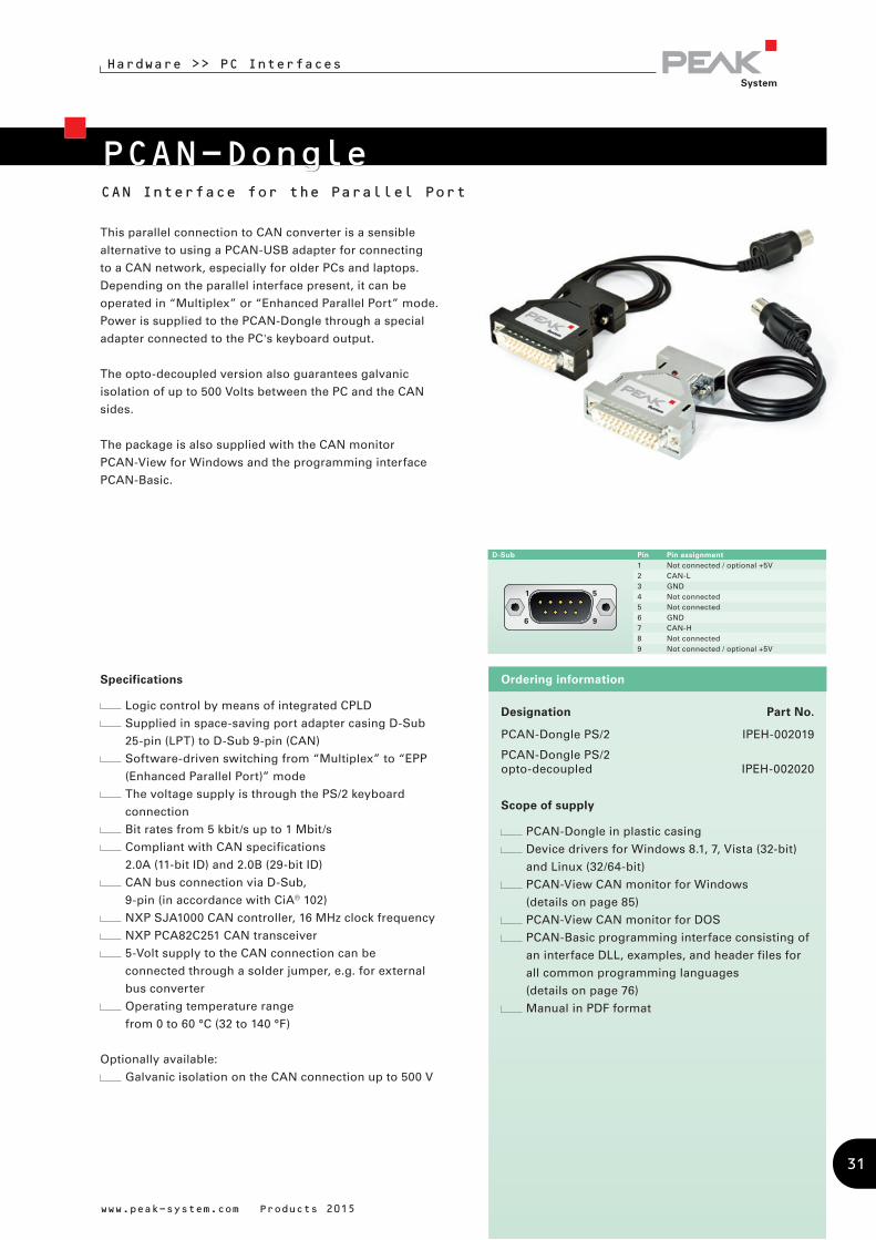
PCAN-DongleCAN Interface for the Parallel Port
This parallel connection to CAN converter is a sensible
alternative to using a PCAN-USB adapter for connecting
to a CAN network, especially for older PCs and laptops.
Depending on the parallel interface present, it can be
operated in “Multiplex” or “Enhanced Parallel Port” mode.
Power is supplied to the PCAN-Dongle through a special
adapter connected to the PC's keyboard output.
The opto-decoupled version also guarantees galvanic
isolation of up to 500 Volts between the PC and the CAN
sides.
The package is also supplied with the CAN monitor
PCAN-View for Windows and the programming interface
PCAN-Basic.
Specifications
Logic control by means of integrated CPLD
Supplied in space-saving port adapter casing D-Sub
25-pin (LPT) to D-Sub 9-pin (CAN)
Software-driven switching from “Multiplex” to “EPP
(Enhanced Parallel Port)” mode
The voltage supply is through the PS/2 keyboard
connection
Bit rates from 5 kbit/s up to 1 Mbit/s
Compliant with CAN specifications
2.0A (11-bit ID) and 2.0B (29-bit ID)
CAN bus connection via D-Sub,
9-pin (in accordance with CiA® 102)
NXP SJA1000 CAN controller, 16 MHz clock frequency
NXP PCA82C251 CAN transceiver
5-Volt supply to the CAN connection can be
connected through a solder jumper, e.g. for external
bus converter
Operating temperature range
from 0 to 60 °C (32 to 140 °F)
Optionally available:
Galvanic isolation on the CAN connection up to 500 V
www.peak-system.com Products 2015
Designation Part No.
PCAN-Dongle PS/2 IPEH-002019
PCAN-Dongle PS/2 opto-decoupled IPEH-002020
Scope of supply
PCAN-Dongle in plastic casing
Device drivers for Windows 8.1, 7, Vista (32-bit)
and Linux (32/64-bit)
PCAN-View CAN monitor for Windows
(details on page 85)
PCAN-View CAN monitor for DOS
PCAN-Basic programming interface consisting of
an interface DLL, examples, and header files for
all common programming languages
(details on page 76)
Manual in PDF format
Ordering information
D-Sub Pin Pin assignment 1 Not connected / optional +5V2 CAN-L3 GND4 Not connected5 Not connected6 GND7 CAN-H8 Not connected9 Not connected / optional +5V
31
Reset & Clock Power
FPGACAN
Transceiver
1 ... 4
SPI FlashProgramming
Interface (optional)
PCI Level
Converter
(optional)
PCI Bus CAN Bus 1 ... 4
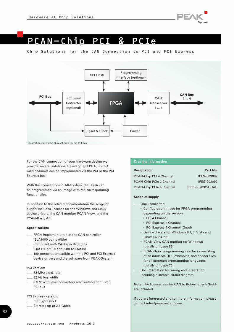
Illustration shows the chip solution for the PCI bus
Hardware >> Chip Solutions
www.peak-system.com Products 2015
PCAN-Chip PCI & PCIeChip Solutions for the CAN Connection to PCI and PCI Express
Designation Part No.
PCAN-Chip PCI 4 Channel IPES-003092
PCAN-Chip PCIe 2 Channel IPES-002092
PCAN-Chip PCIe 4 Channel IPES-002092-QUAD
Scope of supply
One license for:
Configuration image for FPGA programming
depending on the version:
PCI 4 Channel
PCI Express 2 Channel
PCI Express 4 Channel (Quad)
Device drivers for Windows 8.1, 7, Vista and
Linux (32/64-bit)
PCAN-View CAN monitor for Windows
(details on page 85)
PCAN-Basic programming interface consisting
of an interface DLL, examples, and header files
for all common programming languages
(details on page 76)
Documentation for wiring and integration
including a sample circuit diagram
Note: The license fees for CAN to Robert Bosch GmbH
are included.
If you are interested and for more information, please
contact [email protected].
Ordering informationFor the CAN connection of your hardware design we
provide several solutions. Based on an FPGA, up to 4
CAN channels can be implemented via the PCI or the PCI
Express bus.
With the license from PEAK-System, the FPGA can
be programmed via an image with the corresponding
functionality.
In addition to the related documentation the scope of
supply includes licenses for the Windows and Linux
device drivers, the CAN monitor PCAN-View, and the
PCAN-Basic API.
Specifications
FPGA implementation of the CAN controller
(SJA1000 compatible)
Compliant with CAN specifications
2.0A (11-bit ID) and 2.0B (29-bit ID)
100-percent compatible with the PCI and PCI Express
device drivers and the software from PEAK-System
PCI version:
33 MHz clock rate
32 bit bus width
3.3 V; with level converters also suitable for 5-Volt
PCI bus
PCI Express version:
PCI Express x1
Bit rates up to 2.5 Gbit/s
32
PCAN-Chip USB
Hardware >> Chip Solutions
www.peak-system.com Products 2015
Stamp Module for the Implementation of CAN FD to USB Connections
PCAN-Chip USB
Specifications
High-speed USB 2.0 (compatible to USB 1.1 & 3.0)
FPGA implementation of the CAN FD controller
Complies with CAN specifications 2.0 A/B and FD
CAN FD support for ISO and Non-ISO standard
switchable
Measurement of bus load including error frames and
overload frames on the physical bus
Induced error generation for incoming and outgoing
CAN messages
100-percent compatible with the USB device drivers
and the software from PEAK-System
2 connections for status LEDs
Voltage supply 3.3 V DC
New firmware can be loaded via USB
Dimensions: 25 x 30 mm
Extended operating temperature range
from -40 to 85 °C (-40 to 185 °F)
PCAN-Chip USB EvalSpecifications
CAN bus connection via D-Sub,
9-pin (in accordance with CiA® 102)
Slot for CAN transceiver modules by PEAK-System
USB connector type B, standard ESD protection
circuit
LEDs for CAN status and power supply
Voltage supply via USB
Designation Part No.
PCAN-Chip USB IPEH-004025
PCAN-Chip USB Eval IPEH-004026
Scope of supply PCAN-Chip USB
PCAN-Chip USB
Documentation for wiring and integration
including a sample circuit diagram
One license per chip for:
Device drivers for Windows 8.1, 7, Vista and
Linux (32/64-bit)
PCAN-View CAN monitor for Windows
(details on page 85)
PCAN-Basic programming interface consisting
of an interface DLL, examples, and header files
for all common programming languages
(details on page 76)
Scope of supply PCAN-Chip USB Eval
PCAN-Chip USB Eval
PCAN-Chip USB inkl. Lieferumfang
Note: The license fees for CAN to Robert Bosch GmbH
are included.
If you are interested and for more information, please
contact [email protected].
Ordering information
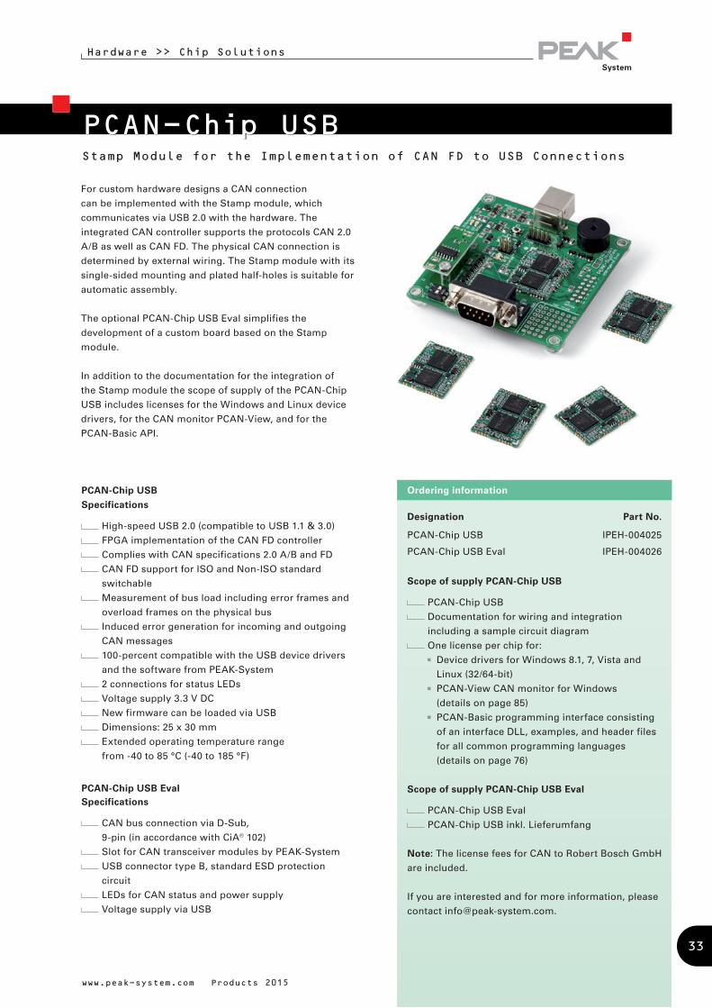
For custom hardware designs a CAN connection
can be implemented with the Stamp module, which
communicates via USB 2.0 with the hardware. The
integrated CAN controller supports the protocols CAN 2.0
A/B as well as CAN FD. The physical CAN connection is
determined by external wiring. The Stamp module with its
single-sided mounting and plated half-holes is suitable for
automatic assembly.
The optional PCAN-Chip USB Eval simplifies the
development of a custom board based on the Stamp
module.
In addition to the documentation for the integration of
the Stamp module the scope of supply of the PCAN-Chip
USB includes licenses for the Windows and Linux device
drivers, for the CAN monitor PCAN-View, and for the
PCAN-Basic API.
33
PCAN-OptoadapterPlug-on Adapter for Decoupling CAN Networks
Hardware >> Couplers & Converters
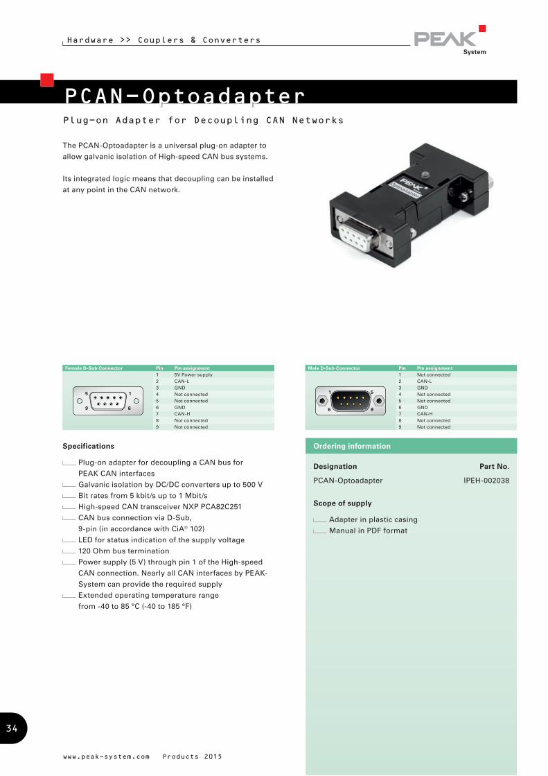
The PCAN-Optoadapter is a universal plug-on adapter to
allow galvanic isolation of High-speed CAN bus systems.
Its integrated logic means that decoupling can be installed
at any point in the CAN network.
www.peak-system.com Products 2015
Designation Part No.
PCAN-Optoadapter IPEH-002038
Scope of supply
Adapter in plastic casing
Manual in PDF format
Ordering informationSpecifications
Plug-on adapter for decoupling a CAN bus for
PEAK CAN interfaces
Galvanic isolation by DC/DC converters up to 500 V
Bit rates from 5 kbit/s up to 1 Mbit/s
High-speed CAN transceiver NXP PCA82C251
CAN bus connection via D-Sub,
9-pin (in accordance with CiA® 102)
LED for status indication of the supply voltage
120 Ohm bus termination
Power supply (5 V) through pin 1 of the High-speed
CAN connection. Nearly all CAN interfaces by PEAK-
System can provide the required supply
Extended operating temperature range
from -40 to 85 °C (-40 to 185 °F)
Male D-Sub Connector Pin Pin assignment1 Not connected2 CAN-L3 GND4 Not connected5 Not connected6 GND7 CAN-H8 Not connected9 Not connected
Female D-Sub Connector Pin Pin assignment1 5V Power supply2 CAN-L3 GND4 Not connected5 Not connected6 GND7 CAN-H8 Not connected9 Not connected
34
PCAN-Repeater DRCAN Repeater for the Decoupling of Bus Segments
Hardware >> Couplers & Converters
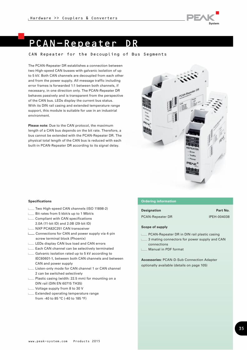
The PCAN-Repeater DR establishes a connection between
two High-speed CAN busses with galvanic isolation of up
to 5 kV. Both CAN channels are decoupled from each other
and from the power supply. All message traffic including
error frames is forwarded 1:1 between both channels, if
necessary, in one direction only. The PCAN-Repeater DR
behaves passively and is transparent from the perspective
of the CAN bus. LEDs display the current bus status.
With its DIN rail casing and extended temperature range
support, this module is suitable for use in an industrial
environment.
Please note: Due to the CAN protocol, the maximum
length of a CAN bus depends on the bit rate. Therefore, a
bus cannot be extended with the PCAN-Repeater DR. The
physical total length of the CAN bus is reduced with each
built-in PCAN-Repeater DR according to its signal delay.
Specifications
Two High-speed CAN channels (ISO 11898-2)
Bit rates from 5 kbit/s up to 1 Mbit/s
Compliant with CAN specifications
2.0A (11-bit ID) and 2.0B (29-bit ID)
NXP PCA82C251 CAN transceiver
Connections for CAN and power supply via 4-pin
screw terminal block (Phoenix)
LEDs display CAN bus load and CAN errors
Each CAN channel can be selectively terminated
Galvanic isolation rated up to 5 kV according to
IEC60601-1, between both CAN channels and between
CAN and power supply
Listen-only mode for CAN channel 1 or CAN channel
2 can be switched selectively
Plastic casing (width: 22.5 mm) for mounting on a
DIN rail (DIN EN 60715 TH35)
Voltage supply from 8 to 30 V
Extended operating temperature range
from -40 to 85 °C (-40 to 185 °F)
www.peak-system.com Products 2015
Designation Part No.
PCAN-Repeater DR IPEH-004038
Scope of supply
PCAN-Repeater DR in DIN rail plastic casing
3 mating connectors for power supply and CAN
connections
Manual in PDF format
Accessories: PCAN-D-Sub Connection Adapter
optionally available (details on page 105)
Ordering information
35
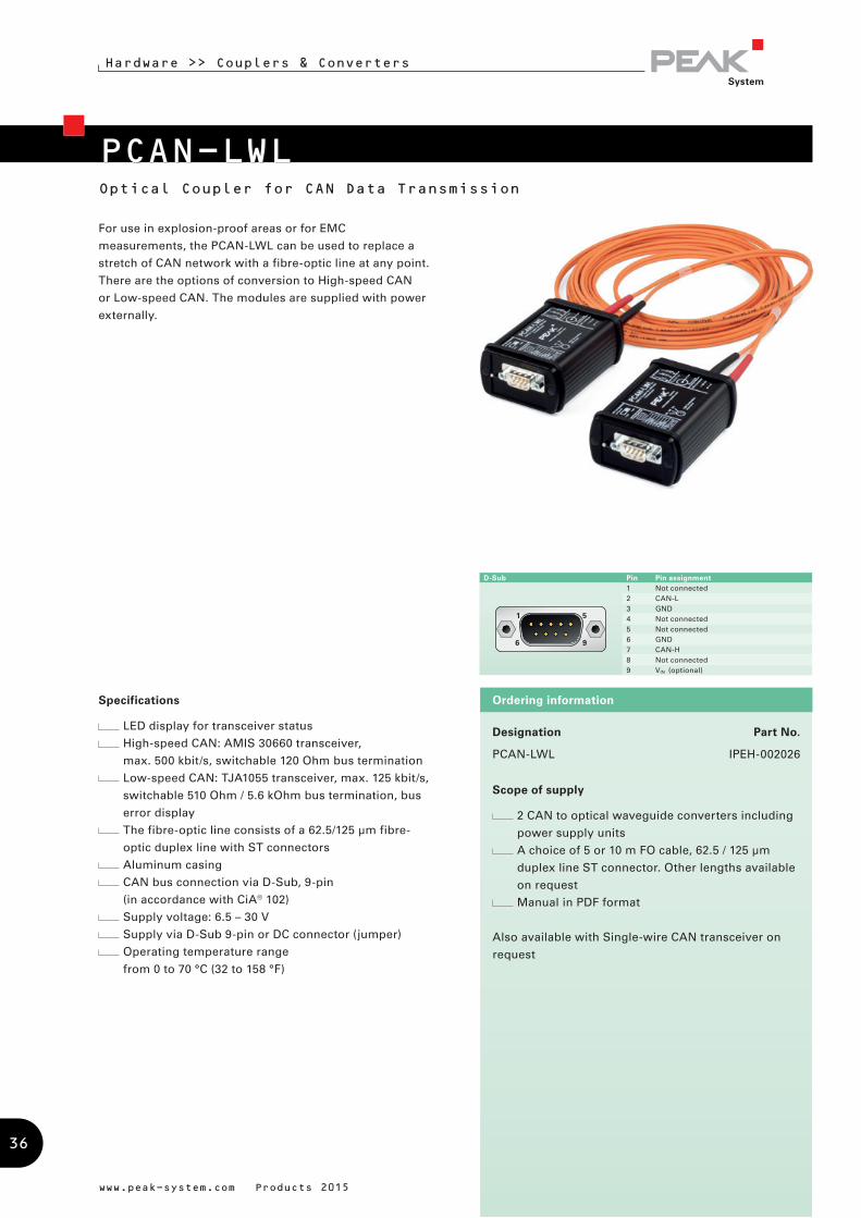
PCAN-LWLOptical Coupler for CAN Data Transmission
Hardware >> Couplers & Converters
For use in explosion-proof areas or for EMC
measurements, the PCAN-LWL can be used to replace a
stretch of CAN network with a fibre-optic line at any point.
There are the options of conversion to High-speed CAN
or Low-speed CAN. The modules are supplied with power
externally.
Designation Part No.
PCAN-LWL IPEH-002026
Scope of supply
2 CAN to optical waveguide converters including
power supply units
A choice of 5 or 10 m FO cable, 62.5 / 125 µm
duplex line ST connector. Other lengths available
on request
Manual in PDF format
Also available with Single-wire CAN transceiver on
request
Ordering informationSpecifications
LED display for transceiver status
High-speed CAN: AMIS 30660 transceiver,
max. 500 kbit/s, switchable 120 Ohm bus termination
Low-speed CAN: TJA1055 transceiver, max. 125 kbit/s,
switchable 510 Ohm / 5.6 kOhm bus termination, bus
error display
The fibre-optic line consists of a 62.5/125 µm fibre-
optic duplex line with ST connectors
Aluminum casing
CAN bus connection via D-Sub, 9-pin
(in accordance with CiA® 102)
Supply voltage: 6.5 – 30 V
Supply via D-Sub 9-pin or DC connector (jumper)
Operating temperature range
from 0 to 70 °C (32 to 158 °F)
www.peak-system.com Products 2015
D-Sub Pin Pin assignment 1 Not connected 2 CAN-L3 GND4 Not connected5 Not connected6 GND7 CAN-H8 Not connected9 VIN (optional)
36
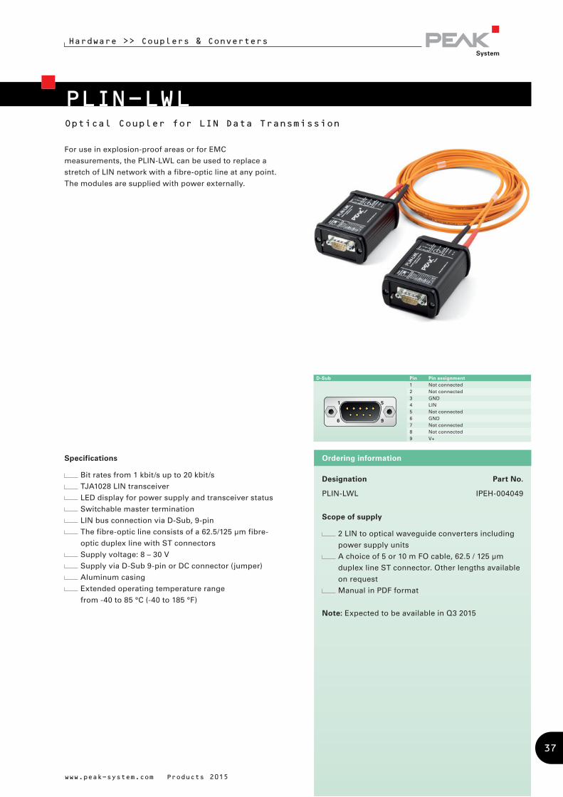
PLIN-LWL
Hardware >> Couplers & Converters
www.peak-system.com Products 2015
Designation Part No.
PLIN-LWL IPEH-004049
Scope of supply
2 LIN to optical waveguide converters including
power supply units
A choice of 5 or 10 m FO cable, 62.5 / 125 µm
duplex line ST connector. Other lengths available
on request
Manual in PDF format
Note: Expected to be available in Q3 2015
Ordering information
D-Sub Pin Pin assignment 1 Not connected 2 Not connected 3 GND4 LIN5 Not connected6 GND7 Not connected 8 Not connected9 V+
Specifications
Bit rates from 1 kbit/s up to 20 kbit/s
TJA1028 LIN transceiver
LED display for power supply and transceiver status
Switchable master termination
LIN bus connection via D-Sub, 9-pin
The fibre-optic line consists of a 62.5/125 µm fibre-
optic duplex line with ST connectors
Supply voltage: 8 – 30 V
Supply via D-Sub 9-pin or DC connector (jumper)
Aluminum casing
Extended operating temperature range
from -40 to 85 °C (-40 to 185 °F)
For use in explosion-proof areas or for EMC
measurements, the PLIN-LWL can be used to replace a
stretch of LIN network with a fibre-optic line at any point.
The modules are supplied with power externally.
Optical Coupler for LIN Data Transmission
37
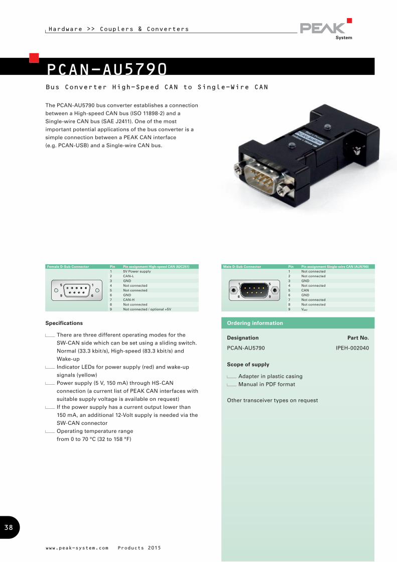
PCAN-AU5790Bus Converter High-Speed CAN to Single-Wire CAN
Hardware >> Couplers & Converters
The PCAN-AU5790 bus converter establishes a connection
between a High-speed CAN bus (ISO 11898-2) and a
Single-wire CAN bus (SAE J2411). One of the most
important potential applications of the bus converter is a
simple connection between a PEAK CAN interface
(e.g. PCAN-USB) and a Single-wire CAN bus.
Specifications
There are three different operating modes for the
SW-CAN side which can be set using a sliding switch.
Normal (33.3 kbit/s), High-speed (83.3 kbit/s) and
Wake-up
Indicator LEDs for power supply (red) and wake-up
signals (yellow)
Power supply (5 V, 150 mA) through HS-CAN
connection (a current list of PEAK CAN interfaces with
suitable supply voltage is available on request)
If the power supply has a current output lower than
150 mA, an additional 12-Volt supply is needed via the
SW-CAN connector
Operating temperature range
from 0 to 70 °C (32 to 158 °F)
www.peak-system.com Products 2015
Designation Part No.
PCAN-AU5790 IPEH-002040
Scope of supply
Adapter in plastic casing
Manual in PDF format
Other transceiver types on request
Ordering information
Male D-Sub Connector Pin Pin assignment Single-wire CAN (AU5790)1 Not connected2 Not connected3 GND4 Not connected5 CAN6 GND7 Not connected8 Not connected9 VBAT
Female D-Sub Connector Pin Pin assignment High-speed CAN (82C251) 1 5V Power supply2 CAN-L3 GND4 Not connected5 Not connected6 GND7 CAN-H8 Not connected9 Not connected / optional +5V
38

PCAN-B10011SBus Converter High-Speed CAN to Truck Trailer CAN
Hardware >> Couplers & Converters
Designation Part No.
PCAN-B10011S IPEH-002041
Scope of supply
Adapter in plastic casing
Power supply unit
Manual in PDF format
Other transceiver types on request
Ordering information
The PCAN-B10011S bus converter establishes a
connection between a High-speed CAN bus (ISO 11898-2)
and a Truck Trailer CAN bus (ISO 11992-1). One of the most
important potential applications of the bus converter is a
simple connection between a PEAK CAN interface
(e.g. PCAN-USB) and a Truck Trailer CAN bus.
Specifications
Direct connection to a High-speed CAN bus through a
D-Sub connector, 9-pin with switchable termination
Direct connection of the Truck Trailer CAN bus
through a D-Sub connector, 9-pin with switchable
termination (master/slave mode)
Connection of the Truck Trailer CAN via 9-pin D-Sub
connector
Normal or listen-only operating mode
Data transfer rates up to 125 kbit/s
Power supply via Truck Trailer CAN bus or self-
sufficient with power supply unit
Adjustable Truck Trailer system voltage (11 - 26 V) for
power through mains power pack
Status display for power supply and error states
via LEDs
Extended operating temperature range
from -40 to 85 °C (-40 to 185 °F)
www.peak-system.com Products 2015
Male D-Sub Connector Pin Pin assignment Truck Trailer CAN (B10011S)1 Not connected2 CAN-L3 GND4 Not connected5 Not connected6 GND7 CAN-H8 Not connected9 VBAT
Female D-Sub Connector Pin Pin assignment High-speed CAN (82C251) 1 Not connected2 CAN-L3 GND4 Not connected5 Not connected6 GND7 CAN-H8 Not connected9 Not connected
39

Designation Part No.
PCAN-TJA1054 IPEH-002039
Scope of supply
Adapter in plastic casing
Manual in PDF format
Other transceiver types on request
Ordering information
Bus Converter High-Speed CAN to Low-Speed CAN
Hardware >> Couplers & Converters
The PCAN-TJA1054 bus converter establishes a
connection between a High-speed CAN bus (ISO 11898-2)
and a Low-speed CAN bus (ISO 11898-3). One of the most
important potential applications of the bus converter is a
simple connection between a PEAK CAN interface
(e.g. PCAN-USB) and a Low-speed CAN bus.
Specifications
Adapter from High-speed CAN to Low-speed CAN
Bit rates up to 125 kbit/s
CAN transceiver NXP PCA82C251 and TJA1055
Termination resistors for Low-speed CAN can be
switched (560 Ohm / 5.66 kOhm)
Power LED
Error LED (Low-speed CAN)
CAN bus connection via D-Sub,
9-pin (in accordance with CiA® 102)
Power supply (5 V) through pin 1 of the High-speed
CAN connection. Nearly all CAN interfaces by PEAK-
System can provide the required supply
Extended operating temperature range
from -40 to 85 °C (-40 to 185 °F)
www.peak-system.com Products 2015
PCAN-TJA1054
Male D-Sub Connector Pin Pin assignment Low-speed CAN (TJA1055)1 Not connected2 CAN-L3 GND4 Not connected5 Not connected6 GND7 CAN-H8 Not connected9 Not connected
Female D-Sub Connector Pin Pin assignment High-speed CAN (82C251) 1 5V Power supply2 CAN-L3 GND4 Not connected5 Not connected6 GND7 CAN-H8 Not connected9 Not connected
40
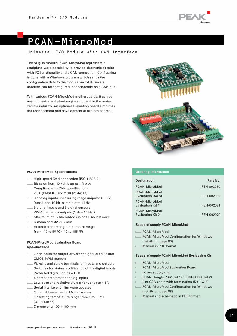
PCAN-MicroModUniversal I/O Module with CAN Interface
Hardware >> I/O Modules
The plug-in module PCAN-MicroMod represents a
straightforward possibility to provide electronic circuits
with I/O functionality and a CAN connection. Configuring
is done with a Windows program which sends the
configuration data to the module via CAN. Several
modules can be configured independently on a CAN bus.
With various PCAN-MicroMod motherboards, it can be
used in device and plant engineering and in the motor
vehicle industry. An optional evaluation board simplifies
the enhancement and development of custom boards.
Designation Part No.
PCAN-MicroMod IPEH-002080
PCAN-MicroMod Evaluation Board IPEH-002082
PCAN-MicroMod Evaluation Kit 1 IPEH-002081
PCAN-MicroMod Evaluation Kit 2 IPEH-002079
Scope of supply PCAN-MicroMod
PCAN-MicroMod
PCAN-MicroMod Configuration for Windows
(details on page 88)
Manual in PDF format
Scope of supply PCAN-MicroMod Evaluation Kit
PCAN-MicroMod
PCAN-MicroMod Evaluation Board
Power supply unit
PCAN-Dongle PS/2 (Kit 1) / PCAN-USB (Kit 2)
2 m CAN cable with termination (Kit 1 & 2)
PCAN-MicroMod Configuration for Windows
(details on page 88)
Manual and schematic in PDF format
Ordering informationPCAN-MicroMod Specifications
High-speed CAN connection (ISO 11898-2)
Bit rates from 10 kbit/s up to 1 Mbit/s
Compliant with CAN specifications
2.0A (11-bit ID) and 2.0B (29-bit ID)
8 analog inputs, measuring range unipolar 0 - 5 V,
(resolution 10 bit, sample rate 1 kHz)
8 digital inputs and 8 digital outputs
PWM/frequency outputs (1 Hz – 10 kHz)
Maximum of 32 MicroMods in one CAN network
Dimensions: 32 x 35 mm
Extended operating temperature range
from -40 to 85 °C (-40 to 185 °F)
PCAN-MicroMod Evaluation BoardSpecifications
Open-collector output driver for digital outputs and
CMOS PWM outputs
Pickoffs and screw terminals for inputs and outputs
Switches for status modification of the digital inputs
Protected digital inputs + LED
4 potentiometers for analog inputs
Low-pass and resistive divider for voltages > 5 V
Serial interface for firmware updates
Optional Low-speed CAN transceiver
Operating temperature range from 0 to 85 °C
(32 to 185 °F)
Dimensions: 100 x 100 mm
www.peak-system.com Products 2015
41
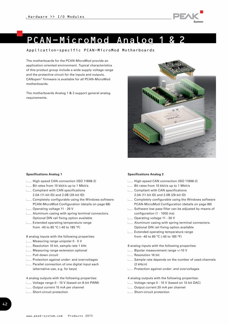
PCAN-MicroMod Analog 1 & 2Application-specific PCAN-MicroMod Motherboards
Hardware >> I/O Modules
The motherboards for the PCAN-MicroMod provide an
application-oriented environment. Typical characteristics
of this product group include a wide supply voltage range
and the protective circuit for the inputs and outputs.
CANopen® firmware is available for all PCAN-MicroMod
motherboards.
The motherboards Analog 1 & 2 support general analog
requirements.
Specifications Analog 1
High-speed CAN connection (ISO 11898-2)
Bit rates from 10 kbit/s up to 1 Mbit/s
Compliant with CAN specifications
2.0A (11-bit ID) and 2.0B (29-bit ID)
Completely configurable using the Windows software
PCAN-MicroMod Configuration (details on page 88)
Operating voltage 11 - 26 V
Aluminum casing with spring terminal connectors.
Optional DIN rail fixing option available
Extended operating temperature range
from -40 to 85 °C (-40 to 185 °F)
8 analog inputs with the following properties:
Measuring range unipolar 0 - 5 V
Resolution 10 bit, sample rate 1 kHz
Measuring range extension optional
Pull-down circuit
Protection against under- and overvoltages
Parallel connection of one digital input each
(alternative use, e.g. for keys)
4 analog outputs with the following properties:
Voltage range 0 - 10 V (based on 8-bit PWM)
Output current 15 mA per channel
Short-circuit protection
Specifications Analog 2
High-speed CAN connection (ISO 11898-2)
Bit rates from 10 kbit/s up to 1 Mbit/s
Compliant with CAN specifications
2.0A (11-bit ID) and 2.0B (29-bit ID)
Completely configurable using the Windows software
PCAN-MicroMod Configuration (details on page 88)
Software low-pass filter can be adjusted by means of
configuration (1 - 1000 ms)
Operating voltage 11 - 30 V
Aluminum casing with spring terminal connectors.
Optional DIN rail fixing option available
Extended operating temperature range
from -40 to 85 °C (-40 to 185 °F)
8 analog inputs with the following properties:
Bipolar measurement range +/-10 V
Resolution 16 bit
Sample rate depends on the number of used channels
(2 kHz/n)
Protection against under- and overvoltages
4 analog outputs with the following properties:
Voltage range 0 - 10 V (based on 12-bit DAC)
Output current 20 mA per channel
Short-circuit protection
www.peak-system.com Products 2015
42
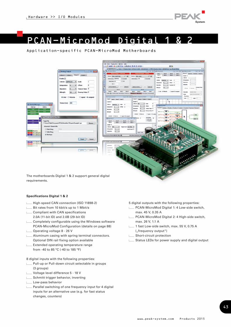
The motherboards Digital 1 & 2 support general digital
requirements.
Specifications Digital 1 & 2
High-speed CAN connection (ISO 11898-2)
Bit rates from 10 kbit/s up to 1 Mbit/s
Compliant with CAN specifications
2.0A (11-bit ID) and 2.0B (29-bit ID)
Completely configurable using the Windows software
PCAN-MicroMod Configuration (details on page 88)
Operating voltage 8 - 26 V
Aluminum casing with spring terminal connectors.
Optional DIN rail fixing option available
Extended operating temperature range
from -40 to 85 °C (-40 to 185 °F)
8 digital inputs with the following properties:
Pull-up or Pull-down circuit selectable in groups
(3 groups)
Voltage level difference 5 - 18 V
Schmitt trigger behavior, inverting
Low-pass behavior
Parallel switching of one frequency input for 4 digital
inputs for an alternative use (e.g. for fast status
changes, counters)
PCAN-MicroMod Digital 1 & 2Application-specific PCAN-MicroMod Motherboards
Hardware >> I/O Modules
5 digital outputs with the following properties:
PCAN-MicroMod Digital 1: 4 Low-side switch,
max. 45 V, 0.35 A
PCAN-MicroMod Digital 2: 4 High-side switch,
max. 26 V, 1.1 A
1 fast Low-side switch, max. 55 V, 0.75 A
(„frequency output“)
Short-circuit protection
Status LEDs for power supply and digital output
www.peak-system.com Products 2015
43
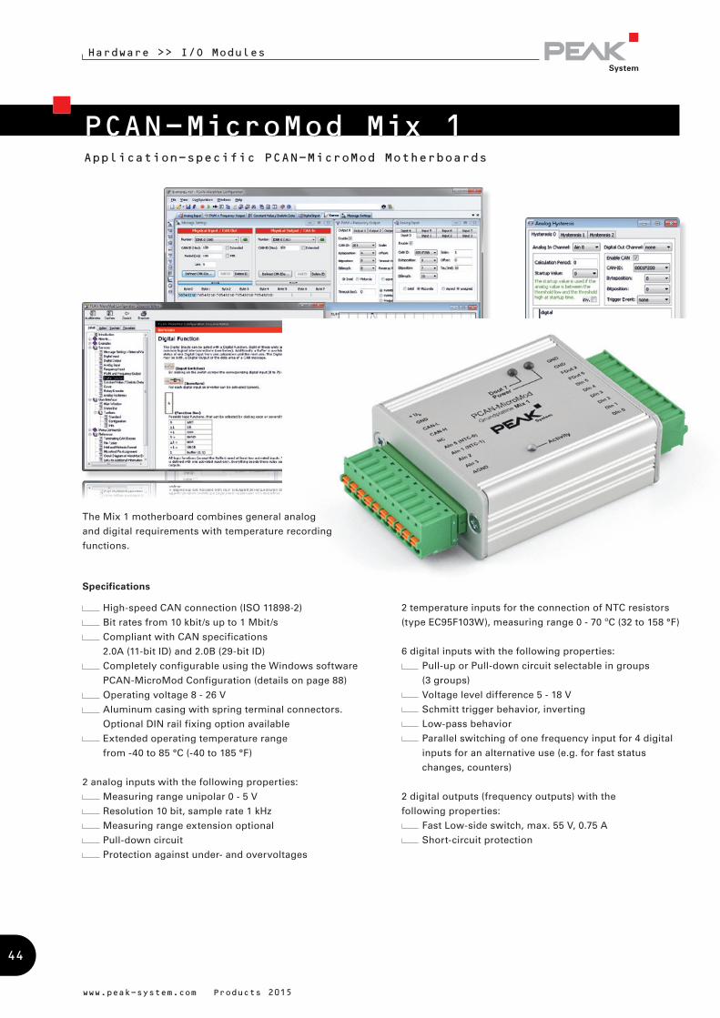
Application-specific PCAN-MicroMod Motherboards
Hardware >> I/O Modules
The Mix 1 motherboard combines general analog
and digital requirements with temperature recording
functions.
2 temperature inputs for the connection of NTC resistors
(type EC95F103W), measuring range 0 - 70 ºC (32 to 158 °F)
6 digital inputs with the following properties:
Pull-up or Pull-down circuit selectable in groups
(3 groups)
Voltage level difference 5 - 18 V
Schmitt trigger behavior, inverting
Low-pass behavior
Parallel switching of one frequency input for 4 digital
inputs for an alternative use (e.g. for fast status
changes, counters)
2 digital outputs (frequency outputs) with the
following properties:
Fast Low-side switch, max. 55 V, 0.75 A
Short-circuit protection
Specifications
High-speed CAN connection (ISO 11898-2)
Bit rates from 10 kbit/s up to 1 Mbit/s
Compliant with CAN specifications
2.0A (11-bit ID) and 2.0B (29-bit ID)
Completely configurable using the Windows software
PCAN-MicroMod Configuration (details on page 88)
Operating voltage 8 - 26 V
Aluminum casing with spring terminal connectors.
Optional DIN rail fixing option available
Extended operating temperature range
from -40 to 85 °C (-40 to 185 °F)
2 analog inputs with the following properties:
Measuring range unipolar 0 - 5 V
Resolution 10 bit, sample rate 1 kHz
Measuring range extension optional
Pull-down circuit
Protection against under- and overvoltages
www.peak-system.com Products 2015
PCAN-MicroMod Mix 1
44
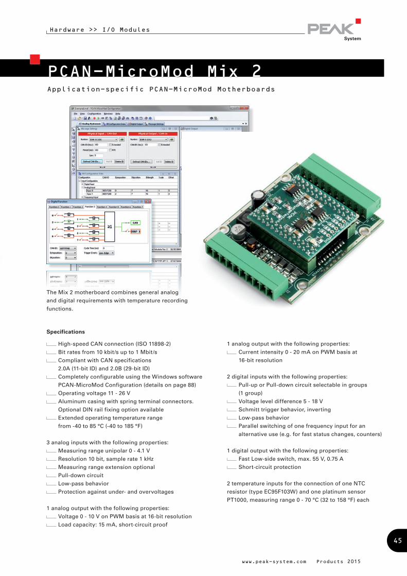
Application-specific PCAN-MicroMod Motherboards
Hardware >> I/O Modules
PCAN-MicroMod Mix 2
1 analog output with the following properties:
Current intensity 0 - 20 mA on PWM basis at
16-bit resolution
2 digital inputs with the following properties:
Pull-up or Pull-down circuit selectable in groups
(1 group)
Voltage level difference 5 - 18 V
Schmitt trigger behavior, inverting
Low-pass behavior
Parallel switching of one frequency input for an
alternative use (e.g. for fast status changes, counters)
1 digital output with the following properties:
Fast Low-side switch, max. 55 V, 0.75 A
Short-circuit protection
2 temperature inputs for the connection of one NTC
resistor (type EC95F103W) and one platinum sensor
PT1000, measuring range 0 - 70 °C (32 to 158 °F) each
Specifications
High-speed CAN connection (ISO 11898-2)
Bit rates from 10 kbit/s up to 1 Mbit/s
Compliant with CAN specifications
2.0A (11-bit ID) and 2.0B (29-bit ID)
Completely configurable using the Windows software
PCAN-MicroMod Configuration (details on page 88)
Operating voltage 11 - 26 V
Aluminum casing with spring terminal connectors.
Optional DIN rail fixing option available
Extended operating temperature range
from -40 to 85 °C (-40 to 185 °F)
3 analog inputs with the following properties:
Measuring range unipolar 0 - 4.1 V
Resolution 10 bit, sample rate 1 kHz
Measuring range extension optional
Pull-down circuit
Low-pass behavior
Protection against under- and overvoltages
1 analog output with the following properties:
Voltage 0 - 10 V on PWM basis at 16-bit resolution
Load capacity: 15 mA, short-circuit proof
The Mix 2 motherboard combines general analog
and digital requirements with temperature recording
functions.
www.peak-system.com Products 2015
45
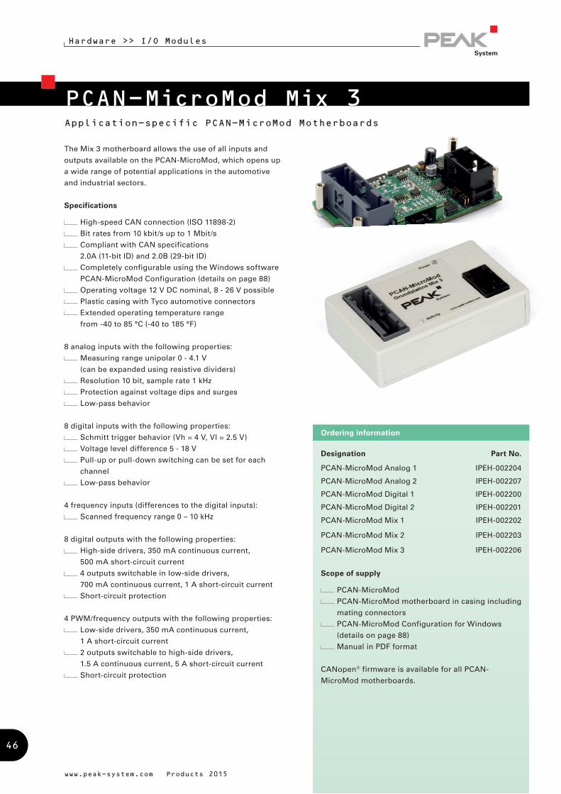
Designation Part No.
PCAN-MicroMod Analog 1 IPEH-002204
PCAN-MicroMod Analog 2 IPEH-002207
PCAN-MicroMod Digital 1 IPEH-002200
PCAN-MicroMod Digital 2 IPEH-002201
PCAN-MicroMod Mix 1 IPEH-002202
PCAN-MicroMod Mix 2 IPEH-002203
PCAN-MicroMod Mix 3 IPEH-002206
Scope of supply
PCAN-MicroMod
PCAN-MicroMod motherboard in casing including
mating connectors
PCAN-MicroMod Configuration for Windows
(details on page 88)
Manual in PDF format
CANopen® firmware is available for all PCAN-
MicroMod motherboards.
Ordering information
Application-specific PCAN-MicroMod Motherboards
Hardware >> I/O Modules
The Mix 3 motherboard allows the use of all inputs and
outputs available on the PCAN-MicroMod, which opens up
a wide range of potential applications in the automotive
and industrial sectors.
Specifications
High-speed CAN connection (ISO 11898-2)
Bit rates from 10 kbit/s up to 1 Mbit/s
Compliant with CAN specifications
2.0A (11-bit ID) and 2.0B (29-bit ID)
Completely configurable using the Windows software
PCAN-MicroMod Configuration (details on page 88)
Operating voltage 12 V DC nominal, 8 - 26 V possible
Plastic casing with Tyco automotive connectors
Extended operating temperature range
from -40 to 85 °C (-40 to 185 °F)
8 analog inputs with the following properties:
Measuring range unipolar 0 - 4.1 V
(can be expanded using resistive dividers)
Resolution 10 bit, sample rate 1 kHz
Protection against voltage dips and surges
Low-pass behavior
8 digital inputs with the following properties:
Schmitt trigger behavior (Vh = 4 V, Vl = 2.5 V)
Voltage level difference 5 - 18 V
Pull-up or pull-down switching can be set for each
channel
Low-pass behavior
4 frequency inputs (differences to the digital inputs):
Scanned frequency range 0 – 10 kHz
8 digital outputs with the following properties:
High-side drivers, 350 mA continuous current,
500 mA short-circuit current
4 outputs switchable in low-side drivers,
700 mA continuous current, 1 A short-circuit current
Short-circuit protection
4 PWM/frequency outputs with the following properties:
Low-side drivers, 350 mA continuous current,
1 A short-circuit current
2 outputs switchable to high-side drivers,
1.5 A continuous current, 5 A short-circuit current
Short-circuit protection
www.peak-system.com Products 2015
PCAN-MicroMod Mix 3
46
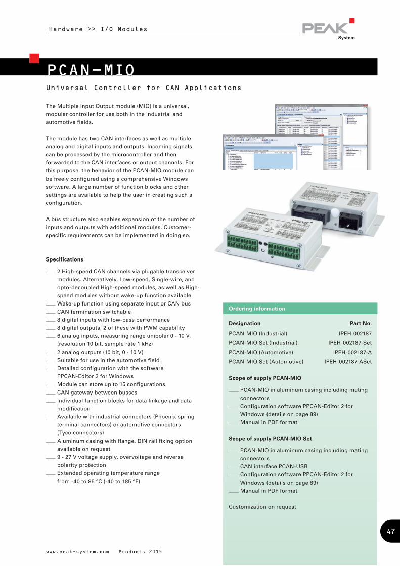
PCAN-MIOUniversal Controller for CAN Applications
Designation Part No.
PCAN-MIO (Industrial) IPEH-002187
PCAN-MIO Set (Industrial) IPEH-002187-Set
PCAN-MIO (Automotive) IPEH-002187-A
PCAN-MIO Set (Automotive) IPEH-002187-ASet
Scope of supply PCAN-MIO
PCAN-MIO in aluminum casing including mating
connectors
Configuration software PPCAN-Editor 2 for
Windows (details on page 89)
Manual in PDF format
Scope of supply PCAN-MIO Set
PCAN-MIO in aluminum casing including mating
connectors
CAN interface PCAN-USB
Configuration software PPCAN-Editor 2 for
Windows (details on page 89)
Manual in PDF format
Customization on request
Ordering information
The Multiple Input Output module (MIO) is a universal,
modular controller for use both in the industrial and
automotive fields.
The module has two CAN interfaces as well as multiple
analog and digital inputs and outputs. Incoming signals
can be processed by the microcontroller and then
forwarded to the CAN interfaces or output channels. For
this purpose, the behavior of the PCAN-MIO module can
be freely configured using a comprehensive Windows
software. A large number of function blocks and other
settings are available to help the user in creating such a
configuration.
A bus structure also enables expansion of the number of
inputs and outputs with additional modules. Customer-
specific requirements can be implemented in doing so.
Specifications
2 High-speed CAN channels via plugable transceiver
modules. Alternatively, Low-speed, Single-wire, and
opto-decoupled High-speed modules, as well as High-
speed modules without wake-up function available
Wake-up function using separate input or CAN bus
CAN termination switchable
8 digital inputs with low-pass performance
8 digital outputs, 2 of these with PWM capability
6 analog inputs, measuring range unipolar 0 - 10 V,
(resolution 10 bit, sample rate 1 kHz)
2 analog outputs (10 bit, 0 - 10 V)
Suitable for use in the automotive field
Detailed configuration with the software
PPCAN-Editor 2 for Windows
Module can store up to 15 configurations
CAN gateway between busses
Individual function blocks for data linkage and data
modification
Available with industrial connectors (Phoenix spring
terminal connectors) or automotive connectors
(Tyco connectors)
Aluminum casing with flange. DIN rail fixing option
available on request
9 - 27 V voltage supply, overvoltage and reverse
polarity protection
Extended operating temperature range
from -40 to 85 °C (-40 to 185 °F)
www.peak-system.com Products 2015
Hardware >> I/O Modules
47
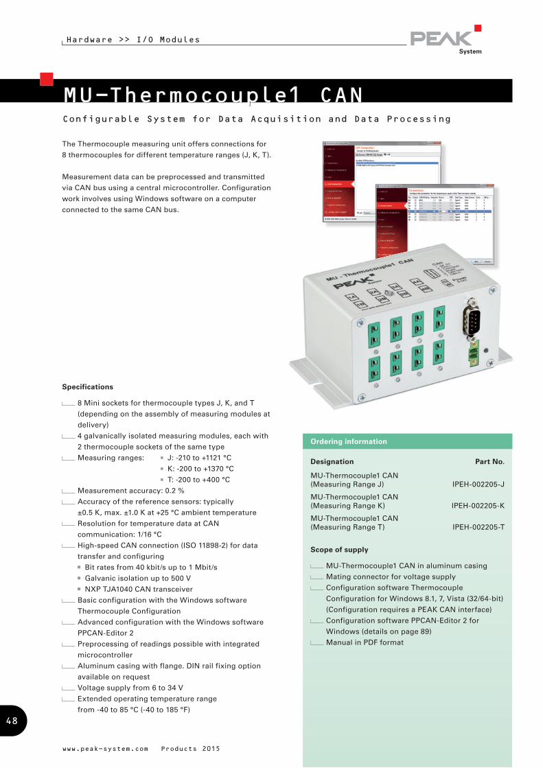
MU-Thermocouple1 CANConfigurable System for Data Acquisition and Data Processing
Hardware >> I/O Modules
Designation Part No.
MU-Thermocouple1 CAN (Measuring Range J) IPEH-002205-J
MU-Thermocouple1 CAN (Measuring Range K) IPEH-002205-K
MU-Thermocouple1 CAN (Measuring Range T) IPEH-002205-T
Scope of supply
MU-Thermocouple1 CAN in aluminum casing
Mating connector for voltage supply
Configuration software Thermocouple
Configuration for Windows 8.1, 7, Vista (32/64-bit)
(Configuration requires a PEAK CAN interface)
Configuration software PPCAN-Editor 2 for
Windows (details on page 89)
Manual in PDF format
Ordering information
The Thermocouple measuring unit offers connections for
8 thermocouples for different temperature ranges (J, K, T).
Measurement data can be preprocessed and transmitted
via CAN bus using a central microcontroller. Configuration
work involves using Windows software on a computer
connected to the same CAN bus.
Specifications
8 Mini sockets for thermocouple types J, K, and T
(depending on the assembly of measuring modules at
delivery)
4 galvanically isolated measuring modules, each with
2 thermocouple sockets of the same type
Measuring ranges: J: -210 to +1121 °C
K: -200 to +1370 °C
T: -200 to +400 °C
Measurement accuracy: 0.2 %
Accuracy of the reference sensors: typically
±0.5 K, max. ±1.0 K at +25 °C ambient temperature
Resolution for temperature data at CAN
communication: 1/16 °C
High-speed CAN connection (ISO 11898-2) for data
transfer and configuring
Bit rates from 40 kbit/s up to 1 Mbit/s
Galvanic isolation up to 500 V
NXP TJA1040 CAN transceiver
Basic configuration with the Windows software
Thermocouple Configuration
Advanced configuration with the Windows software
PPCAN-Editor 2
Preprocessing of readings possible with integrated
microcontroller
Aluminum casing with flange. DIN rail fixing option
available on request
Voltage supply from 6 to 34 V
Extended operating temperature range
from -40 to 85 °C (-40 to 185 °F)
www.peak-system.com Products 2015
48
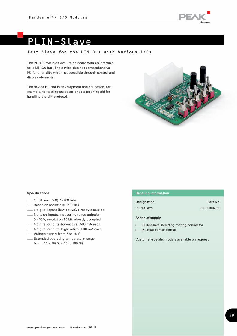
www.peak-system.com Products 2015
Designation Part No.
PLIN-Slave IPEH-004050
Scope of supply
PLIN-Slave including mating connector
Manual in PDF format
Customer-specific models available on request
Ordering informationSpecifications
1 LIN bus (v2.0), 19200 bit/s
Based on Melexis MLX80103
5 digital inputs (low-active), already occupied
3 analog inputs, measuring range unipolar
0 - 18 V, resolution 10 bit, already occupied
4 digital outputs (low-active), 500 mA each
4 digital outputs (high-active), 500 mA each
Voltage supply from 7 to 18 V
Extended operating temperature range
from -40 to 85 °C (-40 to 185 °F)
PLIN-Slave
Hardware >> I/O Modules
Test Slave for the LIN Bus with Various I/Os
The PLIN-Slave is an evaluation board with an interface
for a LIN 2.0 bus. The device also has comprehensive
I/O functionality which is accessible through control and
display elements.
The device is used in development and education, for
example, for testing purposes or as a teaching aid for
handling the LIN protocol.
49
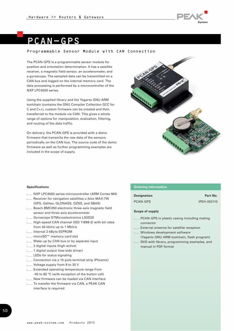
Programmable Sensor Module with CAN Connection
Designation Part No.
PCAN-GPS IPEH-002110
Scope of supply
PCAN-GPS in plastic casing including mating
connector
External antenna for satellite reception
Windows development software
(Yagarto GNU ARM toolchain, flash program)
DVD with library, programming examples, and
manual in PDF format
Ordering information
www.peak-system.com Products 2015
PCAN-GPS
Hardware >> Routers & Gateways
The PCAN-GPS is a programmable sensor module for
position and orientation determination. It has a satellite
receiver, a magnetic field sensor, an accelerometer, and
a gyroscope. The sampled data can be transmitted on a
CAN bus and logged on the internal memory card. The
data processing is performed by a microcontroller of the
NXP LPC4000 series.
Using the supplied library and the Yagarto GNU ARM
toolchain (contains the GNU Compiler Collection GCC for
C and C++), custom firmware can be created and then
transferred to the module via CAN. This gives a whole
range of options for manipulation, evaluation, filtering,
and routing of the data traffic.
On delivery, the PCAN-GPS is provided with a demo
firmware that transmits the raw data of the sensors
periodically on the CAN bus. The source code of the demo
firmware as well as further programming examples are
included in the scope of supply.
Specifications
NXP LPC4000 series microcontroller (ARM Cortex-M4)
Receiver for navigation satellites u-blox MAX-7W
(GPS, Galileo, GLONASS, QZSS, and SBAS)
Bosch BMC050 electronic three-axis magnetic field
sensor and three-axis accelerometer
Gyroscope STMicroelectronics L3GD20
High-speed CAN channel (ISO 11898-2) with bit rates
from 40 kbit/s up to 1 Mbit/s
Internal 2-kByte EEPROM
microSD™ memory card slot
Wake-up by CAN bus or by separate input
2 digital inputs (high-active)
1 digital output (low-side driver)
LEDs for status signaling
Connection via a 10-pole terminal strip (Phoenix)
Voltage supply from 8 to 30 V
Extended operating temperature range from
-40 to 85 °C (with exception of the button cell)
New firmware can be loaded via CAN interface
To transfer the firmware via CAN, a PEAK CAN
interface is required
50

Hardware >> I/O Modules
Designation Part No.
PEAK-gridARM Evaluation Board IPEH-004051
Scope of supply
PEAK-gridARM Evaluation Board
USB connection cable (type B)
Flat ribbon cable for RS-232 debugging port to
D-Sub, 9-pin
Software and Documentation
µClinux-dist development environment
and toolchain
Board support package (BSP) for Linux
with source and binaries
Hardware manual with circuit diagrams,
BSP user guide
Ordering information
www.peak-system.com Products 2015
PEAK-gridARM Evaluation BoardLinux-based Development Platform for the gridARMTM Microcontroller
Specifications
ARM7 gridARMTM microcontroller (80 MHz)
Linux operating system (version 2.6.36)
4 MByte NOR flash with 16-bit data bus access
8 MByte NOR flash with 32-bit data bus access
64 MByte SDRAM with 32-bit data bus access
I²C EEPROM for device configuration
4 MByte SPI flash
Memory card slot for additional memory capacity
Real-time clock (RTC) with battery
Two alternative JTAG sockets
Push button for hardware reset
Voltage supply via USB or an external power supply
unit (8 - 30 V)
Dimensions: 110 x 110 mm
Additional HD44780-compatible text display available
on request
Communication:
Gigabit Ethernet (10/100/1000 Mbit/s)
High-speed CAN channel (ISO 11898-2) with
Bit rates from 5 kbit/s up to 1 Mbit/s
CAN bus connection via D-Sub, 9-pin
(in accordance with CiA® 102)
NXP CAN transceiver PCA82C251
USB 2.0 Full-speed (USB Device Port)
Two RS-232 connectors for debugging and terminal
access
SPI bus (1 MHz) for two external extensions
I²C bus (400 kHz) for external extensions
Inputs and outputs:
8 digital inputs, occupied with 6 push buttons, an RTC
alarm, and memory card detection
8 digital outputs, occupied with 7 LEDs and a buzzer
5 analog inputs, occupied with 4 potentiometers
Optional use of I/O ports with external wiring via
jumpers
LEDs for µC status, supply, CAN, and RS-232
Grid Connect® has developed the ARM7 microcontroller
gridARMTM as System on a Chip solution (SoC) aiming
for embedded applications in the field of industrial
communication. The PEAK-gridARM evaluation board is
a Linux-based development platform for the gridARMTM
microcontroller. It has connectors for Gigabit Ethernet,
High-speed CAN, USB 2.0, RS-232, SPI, and I²C. Digital
and analog inputs of the evaluation board are manipulated
by push buttons and potentiometers. The microcontroller
state as well as the states for supply and data traffic are
indicated by LEDs. A board support package (BSP) for
Linux gives access to the hardware resources of the PEAK-
gridARM evaluation board.
The gridARM™ microcontroller by the U.S. company
Grid Connect is distributed in Europe exclusively by
PEAK-System.
51
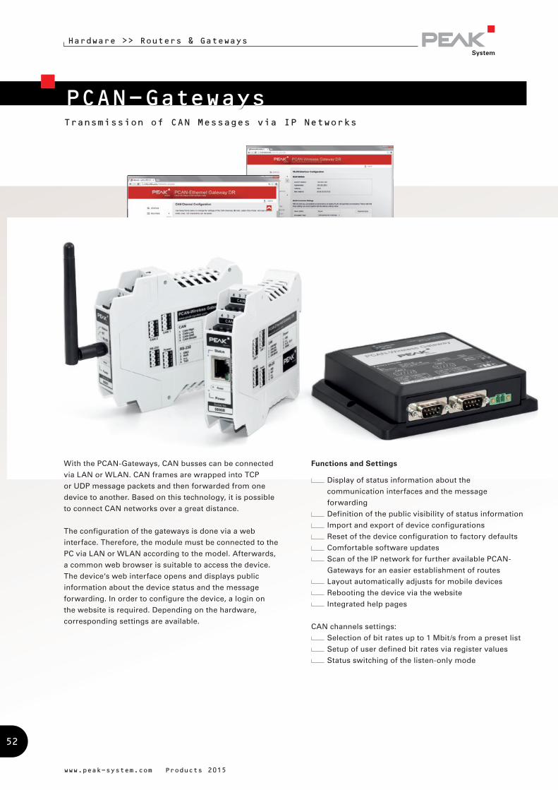
Hardware >> Routers & Gateways
PCAN-Gateways
www.peak-system.com Products 2015
With the PCAN-Gateways, CAN busses can be connected
via LAN or WLAN. CAN frames are wrapped into TCP
or UDP message packets and then forwarded from one
device to another. Based on this technology, it is possible
to connect CAN networks over a great distance.
The configuration of the gateways is done via a web
interface. Therefore, the module must be connected to the
PC via LAN or WLAN according to the model. Afterwards,
a common web browser is suitable to access the device.
The device‘s web interface opens and displays public
information about the device status and the message
forwarding. In order to configure the device, a login on
the website is required. Depending on the hardware,
corresponding settings are available.
Functions and Settings
Display of status information about the
communication interfaces and the message
forwarding
Definition of the public visibility of status information
Import and export of device configurations
Reset of the device configuration to factory defaults
Comfortable software updates
Scan of the IP network for further available PCAN-
Gateways for an easier establishment of routes
Layout automatically adjusts for mobile devices
Rebooting the device via the website
Integrated help pages
CAN channels settings:
Selection of bit rates up to 1 Mbit/s from a preset list
Setup of user defined bit rates via register values
Status switching of the listen-only mode
Transmission of CAN Messages via IP Networks
52
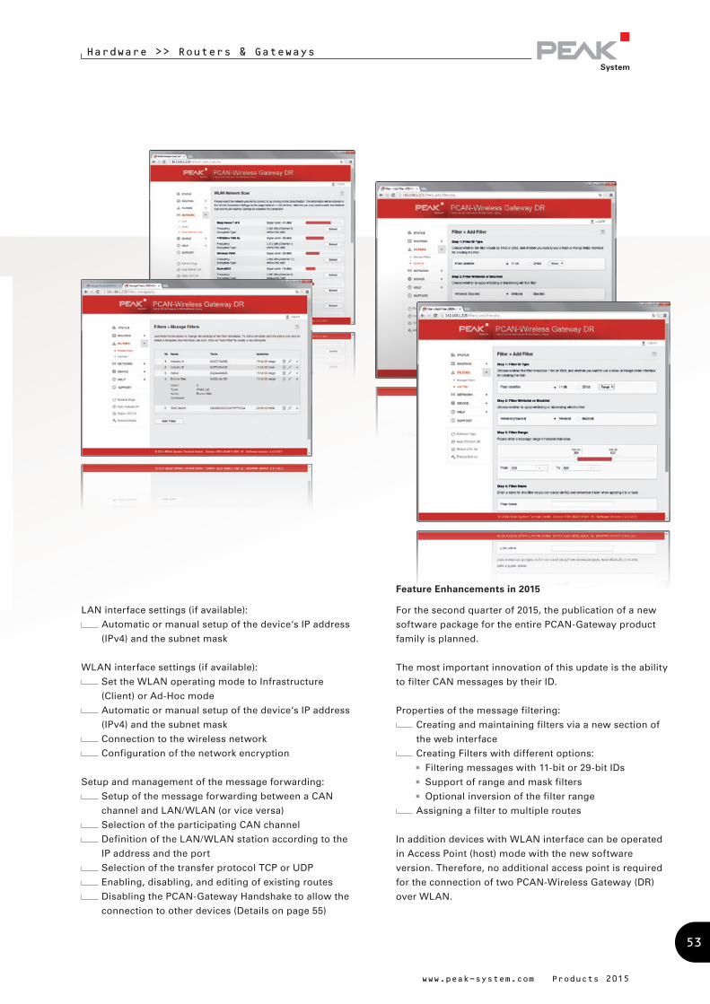
Hardware >> Routers & Gateways
Feature Enhancements in 2015
For the second quarter of 2015, the publication of a new
software package for the entire PCAN-Gateway product
family is planned.
The most important innovation of this update is the ability
to filter CAN messages by their ID.
Properties of the message filtering:
Creating and maintaining filters via a new section of
the web interface
Creating Filters with different options:
Filtering messages with 11-bit or 29-bit IDs
Support of range and mask filters
Optional inversion of the filter range
Assigning a filter to multiple routes
In addition devices with WLAN interface can be operated
in Access Point (host) mode with the new software
version. Therefore, no additional access point is required
for the connection of two PCAN-Wireless Gateway (DR)
over WLAN.
LAN interface settings (if available):
Automatic or manual setup of the device‘s IP address
(IPv4) and the subnet mask
WLAN interface settings (if available):
Set the WLAN operating mode to Infrastructure
(Client) or Ad-Hoc mode
Automatic or manual setup of the device‘s IP address
(IPv4) and the subnet mask
Connection to the wireless network
Configuration of the network encryption
Setup and management of the message forwarding:
Setup of the message forwarding between a CAN
channel and LAN/WLAN (or vice versa)
Selection of the participating CAN channel
Definition of the LAN/WLAN station according to the
IP address and the port
Selection of the transfer protocol TCP or UDP
Enabling, disabling, and editing of existing routes
Disabling the PCAN-Gateway Handshake to allow the
connection to other devices (Details on page 55)
www.peak-system.com Products 2015
53
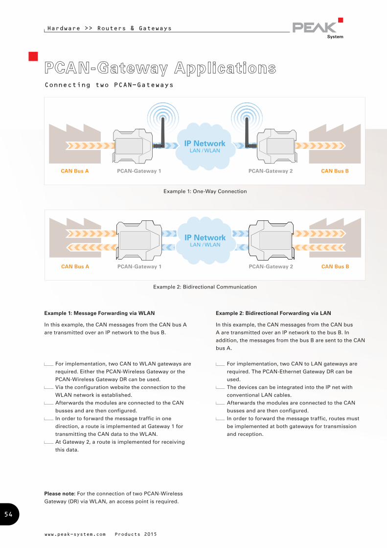
Hardware >> Routers & Gateways
www.peak-system.com Products 2015
Example 1: Message Forwarding via WLAN
In this example, the CAN messages from the CAN bus A
are transmitted over an IP network to the bus B.
For implementation, two CAN to WLAN gateways are
required. Either the PCAN-Wireless Gateway or the
PCAN-Wireless Gateway DR can be used.
Via the configuration website the connection to the
WLAN network is established.
Afterwards the modules are connected to the CAN
busses and are then configured.
In order to forward the message traffic in one
direction, a route is implemented at Gateway 1 for
transmitting the CAN data to the WLAN.
At Gateway 2, a route is implemented for receiving
this data.
Example 2: Bidirectional Forwarding via LAN
In this example, the CAN messages from the CAN bus
A are transmitted over an IP network to the bus B. In
addition, the messages from the bus B are sent to the CAN
bus A.
For implementation, two CAN to LAN gateways are
required. The PCAN-Ethernet Gateway DR can be
used.
The devices can be integrated into the IP net with
conventional LAN cables.
Afterwards the modules are connected to the CAN
busses and are then configured.
In order to forward the message traffic, routes must
be implemented at both gateways for transmission
and reception.
CAN Bus A PCAN-Gateway 1 PCAN-Gateway 2 CAN Bus B
IP NetworkLAN / WLAN
Example 1: One-Way Connection
CAN Bus A PCAN-Gateway 1 PCAN-Gateway 2
IP NetworkLAN / WLAN
CAN Bus B
Example 2: Bidirectional Communication
Connecting two PCAN-Gateways
Please note: For the connection of two PCAN-Wireless
Gateway (DR) via WLAN, an access point is required.
54
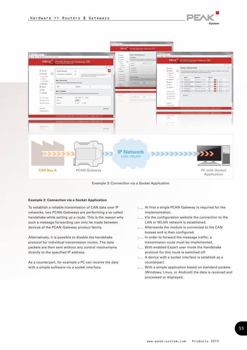
CAN Bus A PCAN-Gateway PC with Socket Application
IP NetworkLAN / WLAN
Example 3: Connection via a Socket Application
Example 3: Connection via a Socket Application
To establish a reliable transmission of CAN data over IP
networks, two PCAN-Gateways are performing a so called
handshake while setting up a route. This is the reason why
such a message forwarding can only be made between
devices of the PCAN-Gateway product family.
Alternatively, it is possible to disable the handshake
protocol for individual transmission routes. The data
packets are then sent without any control mechanisms
directly to the specified IP address.
As a counterpart, for example a PC can receive the data
with a simple software via a socket interface.
At first a single PCAN-Gateway is required for the
implementation.
Via the configuration website the connection to the
LAN or WLAN network is established.
Afterwards the module is connected to the CAN
busses and is then configured.
In order to forward the message traffic, a
transmission route must be implemented.
With enabled Expert user mode the Handshake
protocol for this route is switched off.
A device with a socket interface is establish as a
counterpart.
With a simple application based on standard sockets
(Windows, Linux, or Android) the data is received and
processed or displayed.
Hardware >> Routers & Gateways
www.peak-system.com Products 2015
55

Hardware >> Router & Gateways
www.peak-system.com Produkte 2015
Specifications
Supports the operating systems
Windows 8.1, 7, Vista (32/64-bit)
Connection of several PCAN-Gateways with a
computer via IP-based networks
Optional use of different LAN and WLAN network
adapters
Configuration software to set up and manage
message forwarding
System requirements
Windows 8.1, 7, Vista (32/64-bit)
At least 512 MB RAM and 1 GHz CPU
LAN- or WLAN network interface
Scope of supply
Virtual PCAN-Gateway software package consisting of
configuration software, Windows service, and driver
Documentation in HTML Help format
The current version …
… is available on the product DVD
(supplied with our hardware)
… can be downloaded from the Internet free of charge at
www.peak-system.com
Note: Expected to be available in Q1 2015
Windows Software for Direct Access to PCAN-Gateways
CAN Bus A PCAN-Gateway PC with Virtual PCAN-Gateway
CAN Bus B
IP NetworkLAN / WLAN
Example 4: Connection via the Software Virtual PCAN-Gateway
The Virtual PCAN-Gateway software package provides
access for Windows computers to devices of the PCAN-
Gateway product line over IP-based networks. Various
LAN and WLAN network adapters can be used.
Analog to the bidirectional connection of two PCAN-
Gateways, message forwarding with so-called routes
must be set up between the hardware and the software.
At first, two routes have to be created on the configuration
website of the hardware, one for sending and another for
receiving. Then, the appropriate counterparts of these
routes must be established within the configuration
software.
Due to this connection, the PCAN-Gateways are being
integrated in the established PCAN environment and
can be used like a conventional PEAK CAN interface. For
example, the traffic on the CAN channels can be displayed
and traced by the PCAN-View CAN monitor.
Note: The software requires a PCAN-Gateway as a
counterpart. It is not possible to establish a connection
between two computers with the Virtual PCAN-Gateway.
56
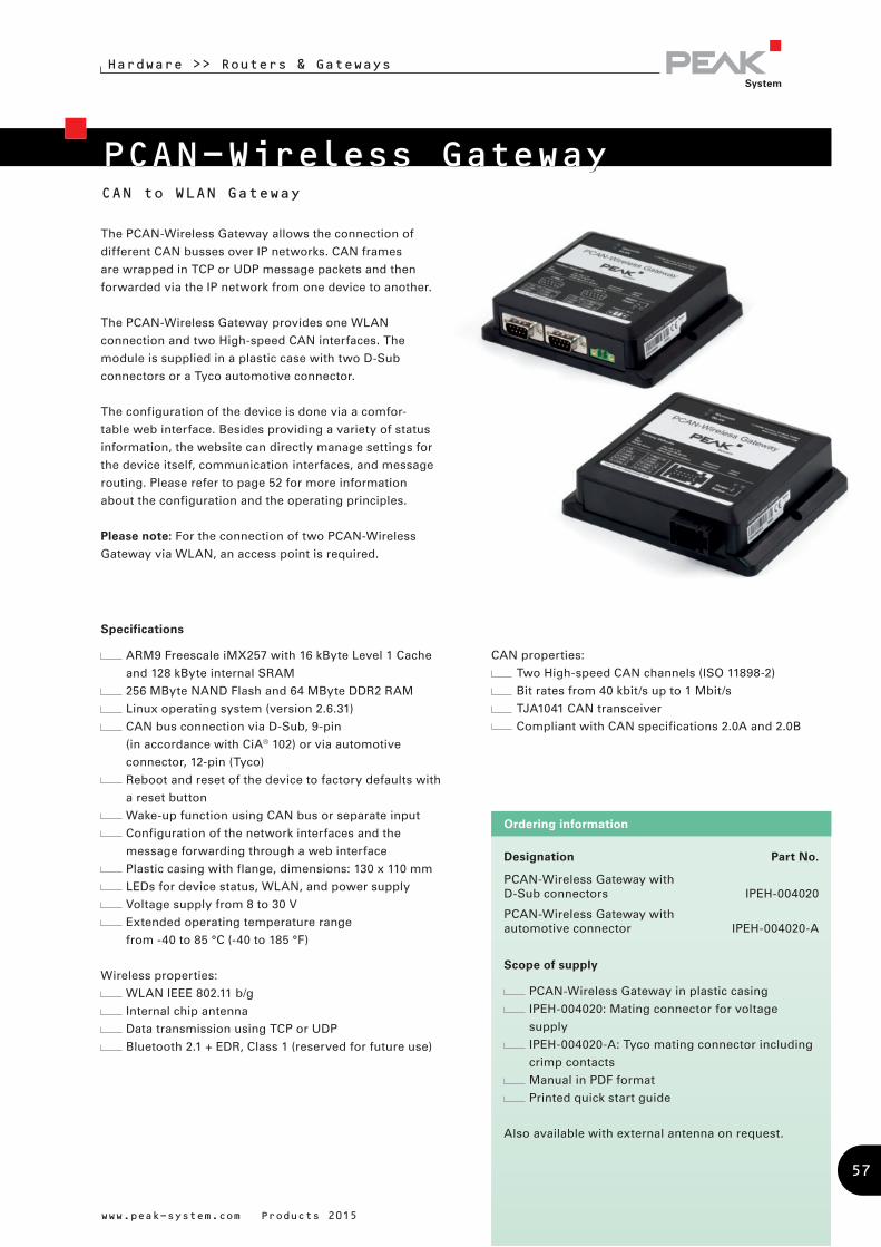
Designation Part No.
PCAN-Wireless Gateway with D-Sub connectors IPEH-004020
PCAN-Wireless Gateway with automotive connector IPEH-004020-A
Scope of supply
PCAN-Wireless Gateway in plastic casing
IPEH-004020: Mating connector for voltage
supply
IPEH-004020-A: Tyco mating connector including
crimp contacts
Manual in PDF format
Printed quick start guide
Also available with external antenna on request.
Ordering information
CAN to WLAN Gateway
Hardware >> Routers & Gateways
PCAN-Wireless Gateway
Specifications
ARM9 Freescale iMX257 with 16 kByte Level 1 Cache
and 128 kByte internal SRAM
256 MByte NAND Flash and 64 MByte DDR2 RAM
Linux operating system (version 2.6.31)
CAN bus connection via D-Sub, 9-pin
(in accordance with CiA® 102) or via automotive
connector, 12-pin (Tyco)
Reboot and reset of the device to factory defaults with
a reset button
Wake-up function using CAN bus or separate input
Configuration of the network interfaces and the
message forwarding through a web interface
Plastic casing with flange, dimensions: 130 x 110 mm
LEDs for device status, WLAN, and power supply
Voltage supply from 8 to 30 V
Extended operating temperature range
from -40 to 85 °C (-40 to 185 °F)
Wireless properties:
WLAN IEEE 802.11 b/g
Internal chip antenna
Data transmission using TCP or UDP
Bluetooth 2.1 + EDR, Class 1 (reserved for future use)
CAN properties:
Two High-speed CAN channels (ISO 11898-2)
Bit rates from 40 kbit/s up to 1 Mbit/s
TJA1041 CAN transceiver
Compliant with CAN specifications 2.0A and 2.0B
www.peak-system.com Products 2015
The PCAN-Wireless Gateway allows the connection of
different CAN busses over IP networks. CAN frames
are wrapped in TCP or UDP message packets and then
forwarded via the IP network from one device to another.
The PCAN-Wireless Gateway provides one WLAN
connection and two High-speed CAN interfaces. The
module is supplied in a plastic case with two D-Sub
connectors or a Tyco automotive connector.
The configuration of the device is done via a comfor-
table web interface. Besides providing a variety of status
information, the website can directly manage settings for
the device itself, communication interfaces, and message
routing. Please refer to page 52 for more information
about the configuration and the operating principles.
Please note: For the connection of two PCAN-Wireless
Gateway via WLAN, an access point is required.
57
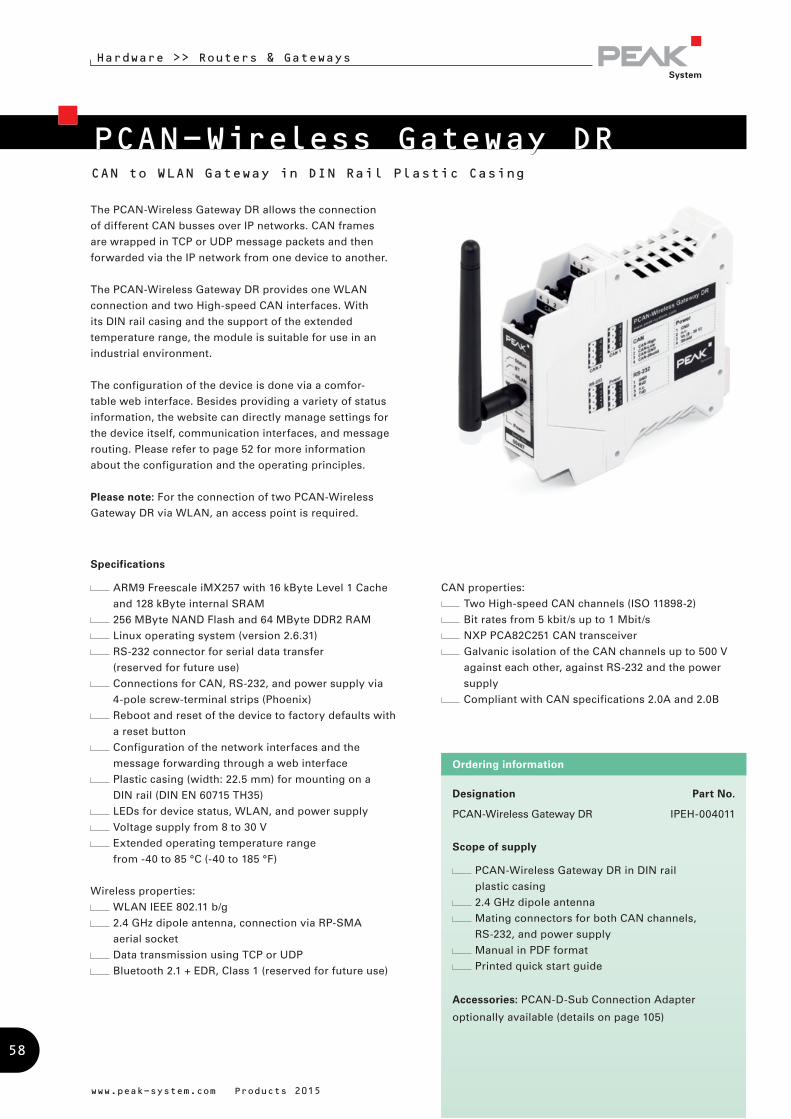
Designation Part No.
PCAN-Wireless Gateway DR IPEH-004011
Scope of supply
PCAN-Wireless Gateway DR in DIN rail
plastic casing
2.4 GHz dipole antenna
Mating connectors for both CAN channels,
RS-232, and power supply
Manual in PDF format
Printed quick start guide
Accessories: PCAN-D-Sub Connection Adapter
optionally available (details on page 105)
Ordering information
Hardware >> Routers & Gateways
www.peak-system.com Products 2015
CAN to WLAN Gateway in DIN Rail Plastic Casing
PCAN-Wireless Gateway DR
CAN properties:
Two High-speed CAN channels (ISO 11898-2)
Bit rates from 5 kbit/s up to 1 Mbit/s
NXP PCA82C251 CAN transceiver
Galvanic isolation of the CAN channels up to 500 V
against each other, against RS-232 and the power
supply
Compliant with CAN specifications 2.0A and 2.0B
Specifications
ARM9 Freescale iMX257 with 16 kByte Level 1 Cache
and 128 kByte internal SRAM
256 MByte NAND Flash and 64 MByte DDR2 RAM
Linux operating system (version 2.6.31)
RS-232 connector for serial data transfer
(reserved for future use)
Connections for CAN, RS-232, and power supply via
4-pole screw-terminal strips (Phoenix)
Reboot and reset of the device to factory defaults with
a reset button
Configuration of the network interfaces and the
message forwarding through a web interface
Plastic casing (width: 22.5 mm) for mounting on a
DIN rail (DIN EN 60715 TH35)
LEDs for device status, WLAN, and power supply
Voltage supply from 8 to 30 V
Extended operating temperature range
from -40 to 85 °C (-40 to 185 °F)
Wireless properties:
WLAN IEEE 802.11 b/g
2.4 GHz dipole antenna, connection via RP-SMA
aerial socket
Data transmission using TCP or UDP
Bluetooth 2.1 + EDR, Class 1 (reserved for future use)
The PCAN-Wireless Gateway DR allows the connection
of different CAN busses over IP networks. CAN frames
are wrapped in TCP or UDP message packets and then
forwarded via the IP network from one device to another.
The PCAN-Wireless Gateway DR provides one WLAN
connection and two High-speed CAN interfaces. With
its DIN rail casing and the support of the extended
temperature range, the module is suitable for use in an
industrial environment.
The configuration of the device is done via a comfor-
table web interface. Besides providing a variety of status
information, the website can directly manage settings for
the device itself, communication interfaces, and message
routing. Please refer to page 52 for more information
about the configuration and the operating principles.
Please note: For the connection of two PCAN-Wireless
Gateway DR via WLAN, an access point is required.
58
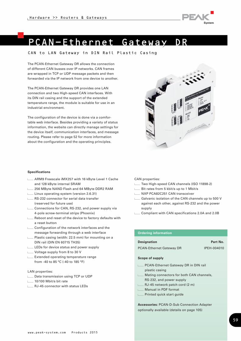
Designation Part No.
PCAN-Ethernet Gateway DR IPEH-004010
Scope of supply
PCAN-Ethernet Gateway DR in DIN rail
plastic casing
Mating connectors for both CAN channels,
RS-232, and power supply
RJ-45 network patch cord (2 m)
Manual in PDF format
Printed quick start guide
Accessories: PCAN-D-Sub Connection Adapter
optionally available (details on page 105)
Ordering information
Hardware >> Routers & Gateways
www.peak-system.com Products 2015
CAN to LAN Gateway in DIN Rail Plastic Casing
PCAN-Ethernet Gateway DR
The PCAN-Ethernet Gateway DR allows the connection
of different CAN busses over IP networks. CAN frames
are wrapped in TCP or UDP message packets and then
forwarded via the IP network from one device to another.
The PCAN-Ethernet Gateway DR provides one LAN
connection and two High-speed CAN interfaces. With
its DIN rail casing and the support of the extended
temperature range, the module is suitable for use in an
industrial environment.
The configuration of the device is done via a comfor-
table web interface. Besides providing a variety of status
information, the website can directly manage settings for
the device itself, communication interfaces, and message
routing. Please refer to page 52 for more information
about the configuration and the operating principles.
CAN properties:
Two High-speed CAN channels (ISO 11898-2)
Bit rates from 5 kbit/s up to 1 Mbit/s
NXP PCA82C251 CAN transceiver
Galvanic isolation of the CAN channels up to 500 V
against each other, against RS-232 and the power
supply
Compliant with CAN specifications 2.0A and 2.0B
Specifications
ARM9 Freescale iMX257 with 16 kByte Level 1 Cache
and 128 kByte internal SRAM
256 MByte NAND Flash and 64 MByte DDR2 RAM
Linux operating system (version 2.6.31)
RS-232 connector for serial data transfer
(reserved for future use)
Connections for CAN, RS-232, and power supply via
4-pole screw-terminal strips (Phoenix)
Reboot and reset of the device to factory defaults with
a reset button
Configuration of the network interfaces and the
message forwarding through a web interface
Plastic casing (width: 22.5 mm) for mounting on a
DIN rail (DIN EN 60715 TH35)
LEDs for device status and power supply
Voltage supply from 8 to 30 V
Extended operating temperature range
from -40 to 85 °C (-40 to 185 °F)
LAN properties:
Data transmission using TCP or UDP
10/100 Mbit/s bit rate
RJ-45 connector with status LEDs
59
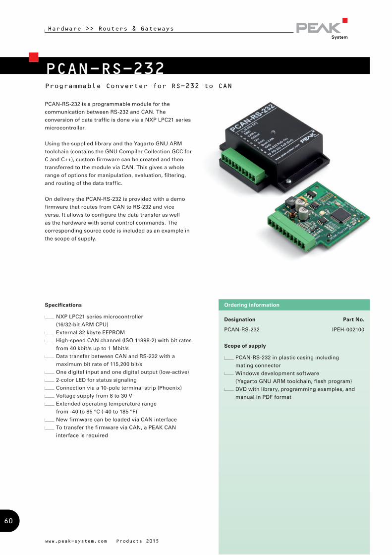
Programmable Converter for RS-232 to CAN
Designation Part No.
PCAN-RS-232 IPEH-002100
Scope of supply
PCAN-RS-232 in plastic casing including
mating connector
Windows development software
(Yagarto GNU ARM toolchain, flash program)
DVD with library, programming examples, and
manual in PDF format
Ordering information
www.peak-system.com Products 2015
PCAN-RS-232
PCAN-RS-232 is a programmable module for the
communication between RS-232 and CAN. The
conversion of data traffic is done via a NXP LPC21 series
microcontroller.
Using the supplied library and the Yagarto GNU ARM
toolchain (contains the GNU Compiler Collection GCC for
C and C++), custom firmware can be created and then
transferred to the module via CAN. This gives a whole
range of options for manipulation, evaluation, filtering,
and routing of the data traffic.
On delivery the PCAN-RS-232 is provided with a demo
firmware that routes from CAN to RS-232 and vice
versa. It allows to configure the data transfer as well
as the hardware with serial control commands. The
corresponding source code is included as an example in
the scope of supply.
Hardware >> Routers & Gateways
Specifications
NXP LPC21 series microcontroller
(16/32-bit ARM CPU)
External 32 kbyte EEPROM
High-speed CAN channel (ISO 11898-2) with bit rates
from 40 kbit/s up to 1 Mbit/s
Data transfer between CAN and RS-232 with a
maximum bit rate of 115,200 bit/s
One digital input and one digital output (low-active)
2-color LED for status signaling
Connection via a 10-pole terminal strip (Phoenix)
Voltage supply from 8 to 30 V
Extended operating temperature range
from -40 to 85 °C (-40 to 185 °F)
New firmware can be loaded via CAN interface
To transfer the firmware via CAN, a PEAK CAN
interface is required
60
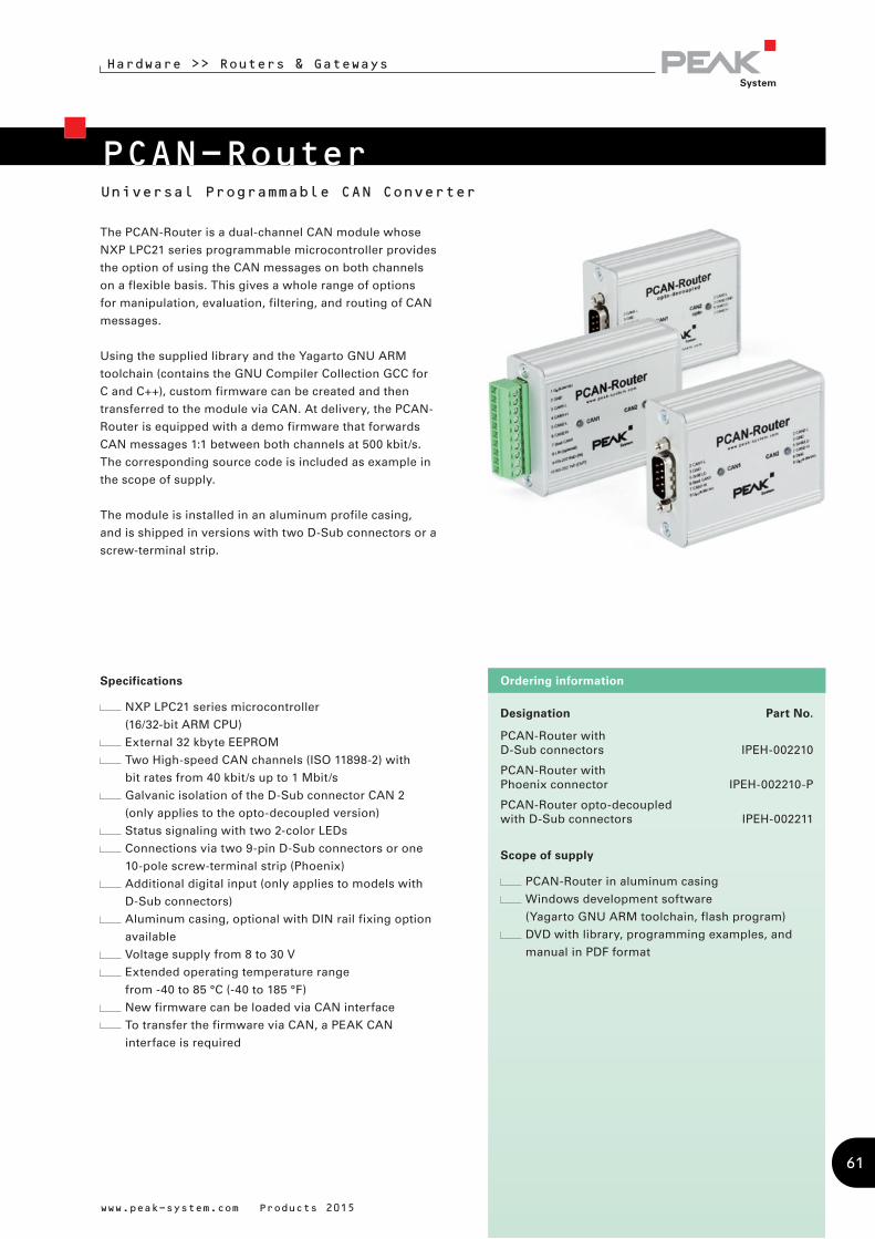
Universal Programmable CAN Converter
Designation Part No.
PCAN-Router with D-Sub connectors IPEH-002210
PCAN-Router with Phoenix connector IPEH-002210-P
PCAN-Router opto-decoupled with D-Sub connectors IPEH-002211
Scope of supply
PCAN-Router in aluminum casing
Windows development software
(Yagarto GNU ARM toolchain, flash program)
DVD with library, programming examples, and
manual in PDF format
Ordering informationSpecifications
NXP LPC21 series microcontroller
(16/32-bit ARM CPU)
External 32 kbyte EEPROM
Two High-speed CAN channels (ISO 11898-2) with
bit rates from 40 kbit/s up to 1 Mbit/s
Galvanic isolation of the D-Sub connector CAN 2
(only applies to the opto-decoupled version)
Status signaling with two 2-color LEDs
Connections via two 9-pin D-Sub connectors or one
10-pole screw-terminal strip (Phoenix)
Additional digital input (only applies to models with
D-Sub connectors)
Aluminum casing, optional with DIN rail fixing option
available
Voltage supply from 8 to 30 V
Extended operating temperature range
from -40 to 85 °C (-40 to 185 °F)
New firmware can be loaded via CAN interface
To transfer the firmware via CAN, a PEAK CAN
interface is required
www.peak-system.com Products 2015
PCAN-Router
Hardware >> Routers & Gateways
The PCAN-Router is a dual-channel CAN module whose
NXP LPC21 series programmable microcontroller provides
the option of using the CAN messages on both channels
on a flexible basis. This gives a whole range of options
for manipulation, evaluation, filtering, and routing of CAN
messages.
Using the supplied library and the Yagarto GNU ARM
toolchain (contains the GNU Compiler Collection GCC for
C and C++), custom firmware can be created and then
transferred to the module via CAN. At delivery, the PCAN-
Router is equipped with a demo firmware that forwards
CAN messages 1:1 between both channels at 500 kbit/s.
The corresponding source code is included as example in
the scope of supply.
The module is installed in an aluminum profile casing,
and is shipped in versions with two D-Sub connectors or a
screw-terminal strip.
61
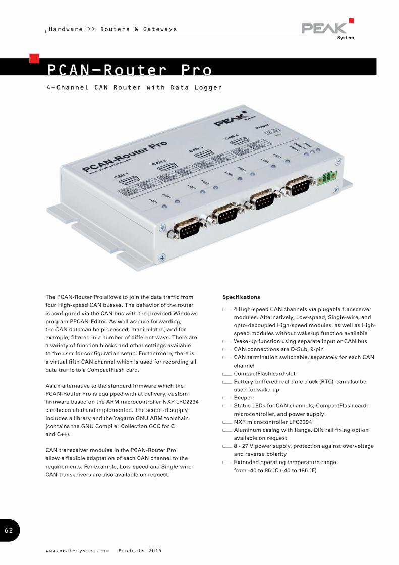
4-Channel CAN Router with Data Logger
www.peak-system.com Products 2015
PCAN-Router Pro
Hardware >> Routers & Gateways
The PCAN-Router Pro allows to join the data traffic from
four High-speed CAN busses. The behavior of the router
is configured via the CAN bus with the provided Windows
program PPCAN-Editor. As well as pure forwarding,
the CAN data can be processed, manipulated, and for
example, filtered in a number of different ways. There are
a variety of function blocks and other settings available
to the user for configuration setup. Furthermore, there is
a virtual fifth CAN channel which is used for recording all
data traffic to a CompactFlash card.
As an alternative to the standard firmware which the
PCAN-Router Pro is equipped with at delivery, custom
firmware based on the ARM microcontroller NXP LPC2294
can be created and implemented. The scope of supply
includes a library and the Yagarto GNU ARM toolchain
(contains the GNU Compiler Collection GCC for C
and C++).
CAN transceiver modules in the PCAN-Router Pro
allow a flexible adaptation of each CAN channel to the
requirements. For example, Low-speed and Single-wire
CAN transceivers are also available on request.
Specifications
4 High-speed CAN channels via plugable transceiver
modules. Alternatively, Low-speed, Single-wire, and
opto-decoupled High-speed modules, as well as High-
speed modules without wake-up function available
Wake-up function using separate input or CAN bus
CAN connections are D-Sub, 9-pin
CAN termination switchable, separately for each CAN
channel
CompactFlash card slot
Battery-buffered real-time clock (RTC), can also be
used for wake-up
Beeper
Status LEDs for CAN channels, CompactFlash card,
microcontroller, and power supply
NXP microcontroller LPC2294
Aluminum casing with flange. DIN rail fixing option
available on request
8 - 27 V power supply, protection against overvoltage
and reverse polarity
Extended operating temperature range
from -40 to 85 °C (-40 to 185 °F)
62

Designation Part No.
PCAN-Router Pro IPEH-002212
Scope of supply
PCAN-Router Pro in aluminum casing including
mating connector for power supply
Configuration software PPCAN-Editor 2 for
Windows (details on page 89)
Conversion software PEAK-Converter for
Windows 8.1, 7, Vista (32/64-bit)
Industrial CompactFlash card (min. 1 GB)
Windows development software
(Yagarto GNU ARM toolchain, flash program)
DVD with library, programming examples, and
manual in PDF format
Customization and customer-specific firmware
available on request
Ordering information
Hardware >> Routers & Gateways
www.peak-system.com Products 2015
Properties of the standard firmware:
Detailed configuration with the software
PPCAN-Editor 2 for Windows
Various function blocks for data processing and
manipulation
Configurable beeper
Configurable CAN channel status LEDs
Recording of CAN data and error frames to a
CompactFlash card
Conversion of logging data to various output formats
using Windows software
Note about the programmability:
Since March 2013, a toolchain and a library are available
for programming custom firmware for the PCAN-Router
Pro. Please note that due to various hardware extensions
only devices with a serial number from 100 can be
equipped with custom firmware.
63
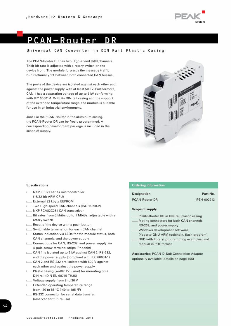
Designation Part No.
PCAN-Router DR IPEH-002213
Scope of supply
PCAN-Router DR in DIN rail plastic casing
Mating connectors for both CAN channels,
RS-232, and power supply
Windows development software
(Yagarto GNU ARM toolchain, flash program)
DVD with library, programming examples, and
manual in PDF format
Accessories: PCAN-D-Sub Connection Adapter
optionally available (details on page 105)
Ordering information
www.peak-system.com Products 2015
Hardware >> Routers & Gateways
Universal CAN Converter in DIN Rail Plastic Casing
PCAN-Router DR
The PCAN-Router DR has two High-speed CAN channels.
Their bit rate is adjusted with a rotary switch on the
device front. The module forwards the message traffic
bi-directionally 1:1 between both connected CAN busses.
The ports of the device are isolated against each other and
against the power supply with at least 500 V. Furthermore,
CAN 1 has a separation voltage of up to 5 kV conforming
with IEC 60601-1. With its DIN rail casing and the support
of the extended temperature range, the module is suitable
for use in an industrial environment.
Just like the PCAN-Router in the aluminum casing,
the PCAN-Router DR can be freely programmed. A
corresponding development package is included in the
scope of supply.
Specifications
NXP LPC21 series microcontroller
(16/32-bit ARM CPU)
External 32 kbyte EEPROM
Two High-speed CAN channels (ISO 11898-2)
NXP PCA82C251 CAN transceiver
Bit rates from 5 kbit/s up to 1 Mbit/s, adjustable with a
rotary switch
Reset of the device with a push button
Switchable termination for each CAN channel
Status indication via LEDs for the module status, both
CAN channels, and the power supply
Connections for CAN, RS-232, and power supply via
4-pole screw-terminal strips (Phoenix)
CAN 1 is isolated up to 5 kV against CAN 2, RS-232,
and the power supply (compliant with IEC 60601-1)
CAN 2 and RS-232 are isolated with 500 V against
each other and against the power supply
Plastic casing (width: 22.5 mm) for mounting on a
DIN rail (DIN EN 60715 TH35)
Voltage supply from 8 to 30 V
Extended operating temperature range
from -40 to 85 °C (-40 to 185 °F)
RS-232 connector for serial data transfer
(reserved for future use)
64

PCAN-LINInterface for LIN, CAN, and RS-232
The PCAN-LIN module enables CAN, LIN, and serial
participants to communicate. The module is supplied in
a plastic casing and includes firmware which enables
data to be exchanged between the different bus systems.
Various modes can be set up with the aid of configuration
software. Then for instance the module acting as the LIN
master can request data and route the incoming LIN data
to the CAN bus and/or the serial interface. Data can be
routed between CAN and LIN with an ID offset.
Specifications
General-purpose gateway (or router when using
Acceptance Code / Acceptance Mask feature) from:
RS-232 to LIN (and back)
CAN to LIN (and back)
RS-232 to CAN (limited bandwidth)
CAN bit rates up to 1 Mbit/s
LIN bit rates of 1 – 20 kbit/s
Transmitting/receiving LIN 1.x and 2.x frames
Available for use as LIN master or slave
Simulation of LIN slaves. Data can be changed via
CAN frames
Processing a user-definable LIN ID list (scheduler with
limited number of entries, cyclic handling if required)
Individual LIN frames can be initiated via CAN or
RS-232
Voltage supply from 9 to 30 V
Extended operating temperature range
from -40 to 85 °C (-40 to 185 °F)
Optionally available:
High-speed (ISO 11898-2) or Low-speed (ISO 11898-3)
CAN transceiver module
Galvanic isolation between RS-232 and CAN/LIN up to
1 kV (only for High-speed CAN)
www.peak-system.com Products 2015
Female D-Sub Connector Pin Pin assignment RS-2321 Not connected2 T x D (RS-232-level)3 R x D (RS-232-level)4 Not connected5 GND6 Not connected7 Not connected8 Not connected9 Not connected
Designation Part No.
PCAN-LIN High-speed CAN IPEH-002025
PCAN-LIN Low-speed CAN IPEH-002028
PCAN-LIN High-speed CAN opto-decoupled IPEH-002029
Scope of supply
PCAN-LIN in plastic casing
Configuration and monitoring tool PCAN-LIN
Config for Windows 8.1, 7, Vista (32/64-bit)
Manual in PDF format
Accessories: PCAN-LIN Connection Cable optionally
available (details on page 112)
Ordering information
Male D-Sub Connector Pin Pin assignment CAN/LIN1 VBat 9 - 30V (Imax ~ 130mA)2 CAN-L3 GND4 LIN data5 Not connected6 GND7 CAN-H8 Not connected9 Not connected
Hardware >> Routers & Gateways
65
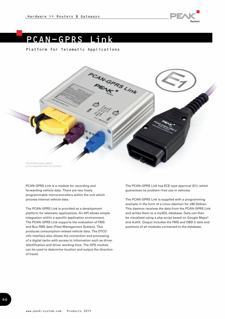
Platform for Telematic Applications
PCAN-GPRS Link is a module for recording and
forwarding vehicle data. There are two freely
programmable microcontrollers within the unit which
process internal vehicle data.
The PCAN-GPRS Link is provided as a development
platform for telematic applications. An API allows simple
integration within a specific application environment.
The PCAN-GPRS Link supports the evaluation of FMS
and Bus FMS data (Fleet Management System). This
produces consumption-related vehicle data. The DTCO
info interface also allows the connection and processing
of a digital tacho with access to information such as driver
identification and driver working time. The GPS module
can be used to determine location and output the direction
of travel.
The PCAN-GPRS Link has ECE type approval (E1), which
guarantees its problem–free use in vehicles.
The PCAN-GPRS Link is supplied with a programming
example in the form of a Linux daemon for x86 Debian.
This daemon receives the data from the PCAN-GPRS Link
and writes them to a mySQL database. Data can then
be visualized using a php script based on Google Maps*
and AJAX. Output includes the FMS and OBD-2 data and
positions of all modules connected to the database.
www.peak-system.com Products 2015
PCAN-GPRS Link
The PCAN-Cable OBD-2 is not supplied with the product.
Hardware >> Routers & Gateways
66
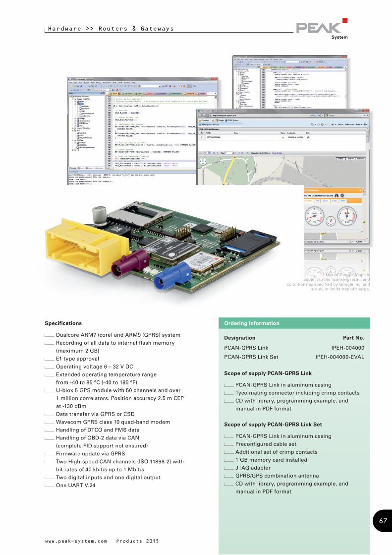
Designation Part No.
PCAN-GPRS Link IPEH-004000
PCAN-GPRS Link Set IPEH-004000-EVAL
Scope of supply PCAN-GPRS Link
PCAN-GPRS Link in aluminum casing
Tyco mating connector including crimp contacts
CD with library, programming example, and
manual in PDF format
Scope of supply PCAN-GPRS Link Set
PCAN-GPRS Link in aluminum casing
Preconfigured cable set
Additional set of crimp contacts
1 GB memory card installed
JTAG adapter
GPRS/GPS combination antenna
CD with library, programming example, and
manual in PDF format
Ordering informationSpecifications
Dualcore ARM7 (core) and ARM9 (GPRS) system
Recording of all data to internal flash memory
(maximum 2 GB)
E1 type approval
Operating voltage 6 – 32 V DC
Extended operating temperature range
from -40 to 85 °C (-40 to 185 °F)
U-blox 5 GPS module with 50 channels and over
1 million correlators. Position accuracy 2.5 m CEP
at -130 dBm
Data transfer via GPRS or CSD
Wavecom GPRS class 10 quad-band modem
Handling of DTCO and FMS data
Handling of OBD-2 data via CAN
(complete PID support not ensured)
Firmware update via GPRS
Two High-speed CAN channels (ISO 11898-2) with
bit rates of 40 kbit/s up to 1 Mbit/s
Two digital inputs and one digital output
One UART V.24
www.peak-system.com Products 2015
* Use of Google Maps is subject to the licensing terms and
conditions as specified by Google Inc. and is only in limits free of charge.
Hardware >> Routers & Gateways
67
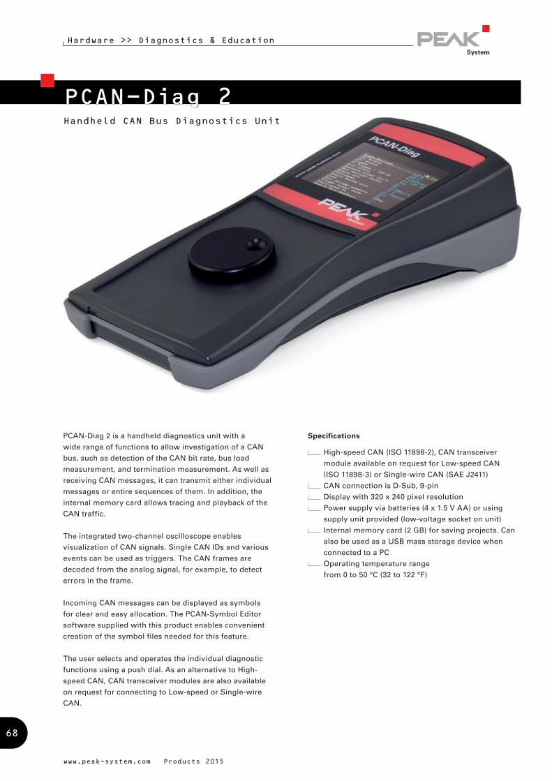
Handheld CAN Bus Diagnostics Unit
Hardware >> Diagnostics & Education
www.peak-system.com Products 2015
PCAN-Diag 2
PCAN-Diag 2 is a handheld diagnostics unit with a
wide range of functions to allow investigation of a CAN
bus, such as detection of the CAN bit rate, bus load
measurement, and termination measurement. As well as
receiving CAN messages, it can transmit either individual
messages or entire sequences of them. In addition, the
internal memory card allows tracing and playback of the
CAN traffic.
The integrated two-channel oscilloscope enables
visualization of CAN signals. Single CAN IDs and various
events can be used as triggers. The CAN frames are
decoded from the analog signal, for example, to detect
errors in the frame.
Incoming CAN messages can be displayed as symbols
for clear and easy allocation. The PCAN-Symbol Editor
software supplied with this product enables convenient
creation of the symbol files needed for this feature.
The user selects and operates the individual diagnostic
functions using a push dial. As an alternative to High-
speed CAN, CAN transceiver modules are also available
on request for connecting to Low-speed or Single-wire
CAN.
Specifications
High-speed CAN (ISO 11898-2), CAN transceiver
module available on request for Low-speed CAN
(ISO 11898-3) or Single-wire CAN (SAE J2411)
CAN connection is D-Sub, 9-pin
Display with 320 x 240 pixel resolution
Power supply via batteries (4 x 1.5 V AA) or using
supply unit provided (low-voltage socket on unit)
Internal memory card (2 GB) for saving projects. Can
also be used as a USB mass storage device when
connected to a PC
Operating temperature range
from 0 to 50 °C (32 to 122 °F)
68
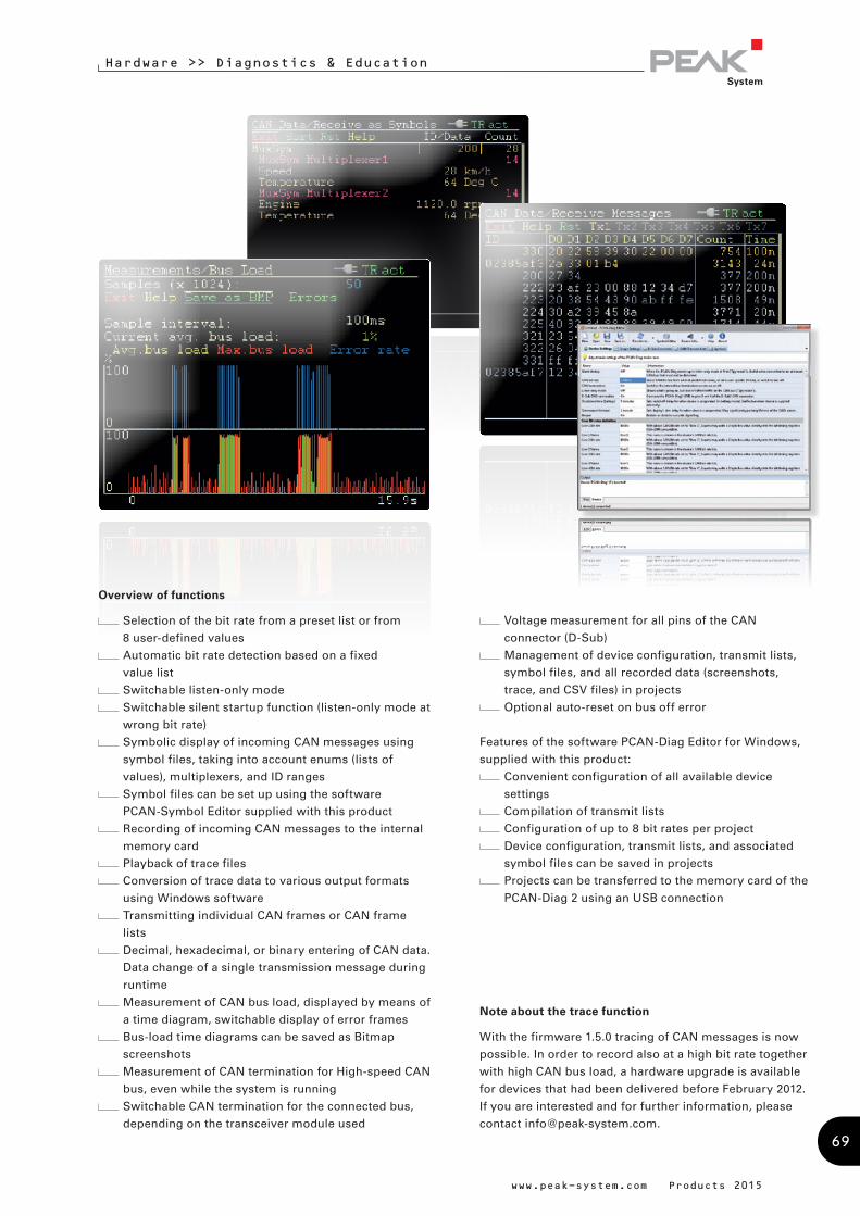
Hardware >> Diagnostics & Education
Overview of functions
Selection of the bit rate from a preset list or from
8 user-defined values
Automatic bit rate detection based on a fixed
value list
Switchable listen-only mode
Switchable silent startup function (listen-only mode at
wrong bit rate)
Symbolic display of incoming CAN messages using
symbol files, taking into account enums (lists of
values), multiplexers, and ID ranges
Symbol files can be set up using the software
PCAN-Symbol Editor supplied with this product
Recording of incoming CAN messages to the internal
memory card
Playback of trace files
Conversion of trace data to various output formats
using Windows software
Transmitting individual CAN frames or CAN frame
lists
Decimal, hexadecimal, or binary entering of CAN data.
Data change of a single transmission message during
runtime
Measurement of CAN bus load, displayed by means of
a time diagram, switchable display of error frames
Bus-load time diagrams can be saved as Bitmap
screenshots
Measurement of CAN termination for High-speed CAN
bus, even while the system is running
Switchable CAN termination for the connected bus,
depending on the transceiver module used
Voltage measurement for all pins of the CAN
connector (D-Sub)
Management of device configuration, transmit lists,
symbol files, and all recorded data (screenshots,
trace, and CSV files) in projects
Optional auto-reset on bus off error
Features of the software PCAN-Diag Editor for Windows,
supplied with this product:
Convenient configuration of all available device
settings
Compilation of transmit lists
Configuration of up to 8 bit rates per project
Device configuration, transmit lists, and associated
symbol files can be saved in projects
Projects can be transferred to the memory card of the
PCAN-Diag 2 using an USB connection
Note about the trace function
With the firmware 1.5.0 tracing of CAN messages is now
possible. In order to record also at a high bit rate together
with high CAN bus load, a hardware upgrade is available
for devices that had been delivered before February 2012.
If you are interested and for further information, please
contact [email protected].
www.peak-system.com Products 2015
69
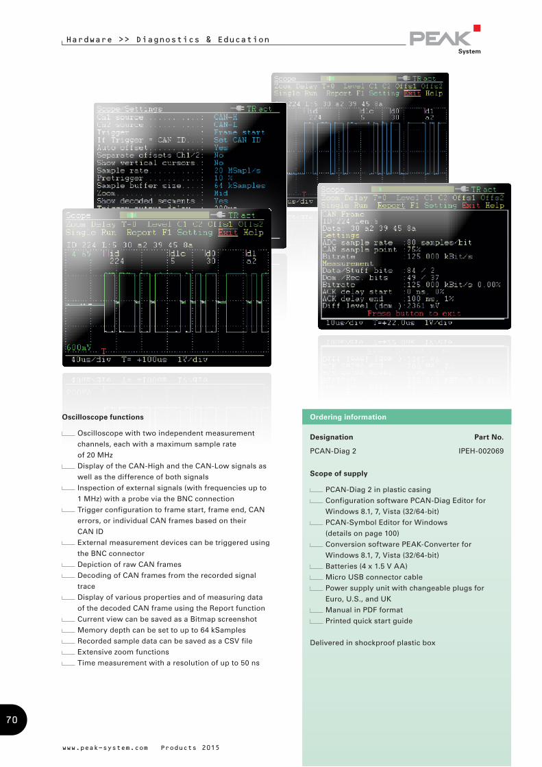
www.peak-system.com Products 2015
Designation Part No.
PCAN-Diag 2 IPEH-002069
Scope of supply
PCAN-Diag 2 in plastic casing
Configuration software PCAN-Diag Editor for
Windows 8.1, 7, Vista (32/64-bit)
PCAN-Symbol Editor for Windows
(details on page 100)
Conversion software PEAK-Converter for
Windows 8.1, 7, Vista (32/64-bit)
Batteries (4 x 1.5 V AA)
Micro USB connector cable
Power supply unit with changeable plugs for
Euro, U.S., and UK
Manual in PDF format
Printed quick start guide
Delivered in shockproof plastic box
Ordering informationOscilloscope functions
Oscilloscope with two independent measurement
channels, each with a maximum sample rate
of 20 MHz
Display of the CAN-High and the CAN-Low signals as
well as the difference of both signals
Inspection of external signals (with frequencies up to
1 MHz) with a probe via the BNC connection
Trigger configuration to frame start, frame end, CAN
errors, or individual CAN frames based on their
CAN ID
External measurement devices can be triggered using
the BNC connector
Depiction of raw CAN frames
Decoding of CAN frames from the recorded signal
trace
Display of various properties and of measuring data
of the decoded CAN frame using the Report function
Current view can be saved as a Bitmap screenshot
Memory depth can be set to up to 64 kSamples
Recorded sample data can be saved as a CSV file
Extensive zoom functions
Time measurement with a resolution of up to 50 ns
Hardware >> Diagnostics & Education
70

www.peak-system.com Products 2015
PCAN-MiniDisplayVisualization and Recording of CAN Data
Hardware >> Diagnostics & Education
The PCAN-MiniDisplay is used as a human-machine
interface for the visualization of CAN data. For the
connection to the CAN bus, it has a High-speed and a
Single-wire CAN connector. The graphic representation
of incoming CAN data is configured before using the unit
and then is performed on a TFT display.
Besides the display of CAN data, the PCAN-MiniDisplay
can also be used for data logging. The data traffic is
recorded to a memory card and can be analyzed on a PC
later on.
In addition to the built-in PCAN-MiniDisplay there is a
version in plastic casing with push buttons available. This
can be used to create and evaluate application-specific
configurations. Furthermore, the user can switch between
different configurations during operation.
Specifications
CAN connection via a High-speed CAN and a Single-
wire CAN channel (ISO 11898-2, SAE J2411)
TFT display with 320 x 240 pixel resolution
High-speed USB 2.0 port for access to the memory
card using a PC
Slot for microSD memory card (max. 32 GByte)
Freely configurable visualization of CAN data via
text files
Running configurations from the memory card
Optional auto-start of a single configuration using a
default name
Recording of incoming CAN messages to the internal
memory card
Conversion of trace data to various output formats
using Windows software
Filtering of CAN IDs per CAN channel
Wake-up function via CAN
Dimensions: 70 x 50 mm
Voltage supply from 8 to 27 V
Extended operating temperature range
from -40 to 85 °C (-40 to 185 °F)
Optionally available: PCAN-MiniDisplay Case
Device in plastic casing with 3 push buttons for menu
navigation and to switch between multiple display
configurations
Designation Part No.
PCAN-MiniDisplay IPEH-002262
PCAN-MiniDisplay Case IPEH-002262-KSM01
Scope of supply PCAN-MiniDisplay
PCAN-MiniDisplay
Conversion software PEAK-Converter for
Windows 8.1, 7, Vista (32/64-bit)
Manual in PDF format
Scope of supply PCAN-MiniDisplay Case
PCAN-MiniDisplay in plastic casing
Cable set for power supply, CAN, and
digital inputs
Conversion software PEAK-Converter for
Windows 8.1, 7, Vista (32/64-bit)
Manual in PDF format
Ordering information
71
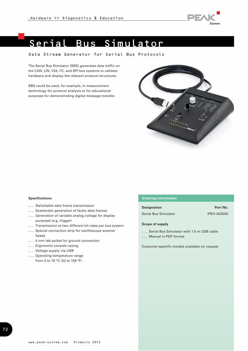
The Serial Bus Simulator (SBS) generates data traffic on
the CAN, LIN, V24, I2C, and SPI bus systems to validate
hardware and display the relevant protocol structures.
SBS could be used, for example, in measurement
technology for protocol analysis or for educational
purposes for demonstrating digital message transfer.
www.peak-system.com Products 2015
Designation Part No.
Serial Bus Simulator IPEH-003050
Scope of supply
Serial Bus Simulator with 1.5 m USB cable
Manual in PDF format
Customer-specific models available on request
Ordering information
Serial Bus SimulatorData Stream Generator for Serial Bus Protocols
Hardware >> Diagnostics & Education
Specifications
Switchable data frame transmission
Systematic generation of faulty data frames
Generation of variable analog voltage for display
purposes (e.g. trigger)
Transmission at two different bit rates per bus system
Special connection strip for oscilloscope scanner
heads
4 mm lab socket for ground connection
Ergonomic console casing
Voltage supply via USB
Operating temperature range
from 0 to 70 °C (32 to 158 °F)
72
Development Packages
PC Software
CAN development systems for Windows 8.1, 7, Vista, CE 6.x and for Linux
Programming interfaces for various protocols and standards
Software to monitor and diagnose CAN and LIN busses
Programs for recording, playback, and simulation of message traffic
Configuration software for CAN hardware from PEAK-System
PEAK-System Technik GmbH designs customer-specific software for
PC and embedded systems. We support you from the idea through to
the finished product.
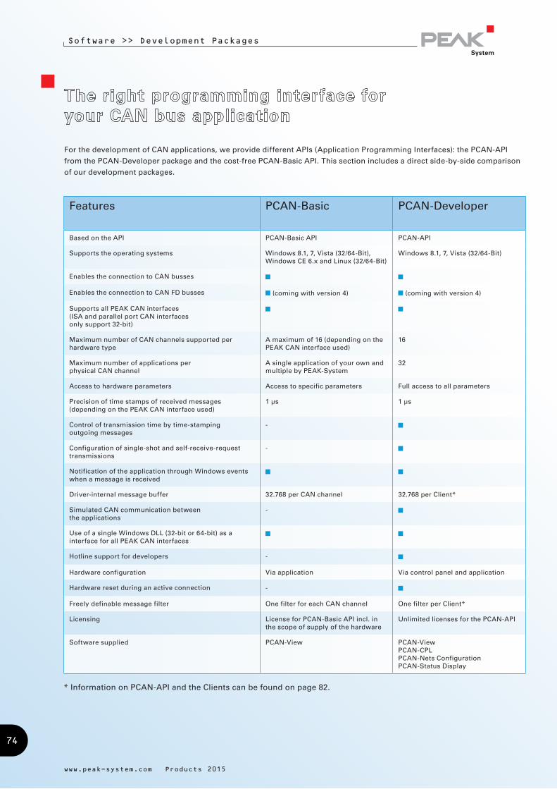
Software >> Development Packages
www.peak-system.com Products 2015
For the development of CAN applications, we provide different APIs (Application Programming Interfaces): the PCAN-API
from the PCAN-Developer package and the cost-free PCAN-Basic API. This section includes a direct side-by-side comparison
of our development packages.
* Information on PCAN-API and the Clients can be found on page 82.
Features PCAN-Basic PCAN-Developer
Based on the API PCAN-Basic API PCAN-API
Supports the operating systems Windows 8.1, 7, Vista (32/64-Bit), Windows CE 6.x and Linux (32/64-Bit)
Windows 8.1, 7, Vista (32/64-Bit)
Enables the connection to CAN busses
Enables the connection to CAN FD busses (coming with version 4) (coming with version 4)
Supports all PEAK CAN interfaces (ISA and parallel port CAN interfaces only support 32-bit)
Maximum number of CAN channels supported per hardware type
A maximum of 16 (depending on the PEAK CAN interface used)
16
Maximum number of applications per physical CAN channel
A single application of your own and multiple by PEAK-System
32
Access to hardware parameters Access to specific parameters Full access to all parameters
Precision of time stamps of received messages (depending on the PEAK CAN interface used)
1 µs 1 µs
Control of transmission time by time-stamping outgoing messages
-
Configuration of single-shot and self-receive-request transmissions
-
Notification of the application through Windows events when a message is received
Driver-internal message buffer 32.768 per CAN channel 32.768 per Client*
Simulated CAN communication between the applications
-
Use of a single Windows DLL (32-bit or 64-bit) as a interface for all PEAK CAN interfaces
Hotline support for developers -
Hardware configuration Via application Via control panel and application
Hardware reset during an active connection -
Freely definable message filter One filter for each CAN channel One filter per Client*
Licensing License for PCAN-Basic API incl. in the scope of supply of the hardware
Unlimited licenses for the PCAN-API
Software supplied PCAN-View PCAN-ViewPCAN-CPLPCAN-Nets ConfigurationPCAN-Status Display
74

Software >> Development Packages
PCAN-BasicDevelopment of applications with CAN and CAN FD connections
PCAN-ISO-TPTransfer of data packages
according to ISO-TP (ISO 15765-2)
PCAN-XCPCommunication with ECUs according to the Universal
Measurement and Calibration Protocol (XCP)
PCAN-UDSCommunication with ECUs
according to UDS (ISO 14229-1)
PCAN-OBD-2Vehicle diagnostics according to
OBD-2 (ISO 15765-4)
PCAN-CCPCommunication with ECUs
according to the CAN Calibration Protocol (CCP)
Dependencies of the different programming interfaces
The automotive sector has standardized protocols for communication with control units as well as the exchange of diagnostic
data and big data packages via CAN. We have implemented programming interfaces for several standards. They are based on
the CAN connection of PCAN-Basic.
The APIs are available free of charge and can be downloaded from our website. They each contain DLLs for 32-bit and
64-bit Windows applications, header files for various programming languages, programming examples in C++, and detailed
documentation.
Note: The programming interfaces can only be used with PC CAN interfaces from PEAK-System.
www.peak-system.com Products 2015
75
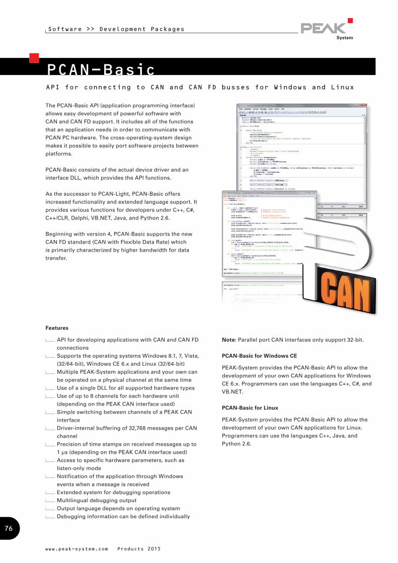
PCAN-Basic
Software >> Development Packages
www.peak-system.com Products 2015
API for connecting to CAN and CAN FD busses for Windows and Linux
The PCAN-Basic API (application programming interface)
allows easy development of powerful software with
CAN and CAN FD support. It includes all of the functions
that an application needs in order to communicate with
PCAN PC hardware. The cross-operating-system design
makes it possible to easily port software projects between
platforms.
PCAN-Basic consists of the actual device driver and an
interface DLL, which provides the API functions.
As the successor to PCAN-Light, PCAN-Basic offers
increased functionality and extended language support. It
provides various functions for developers under C++, C#,
C++/CLR, Delphi, VB.NET, Java, and Python 2.6.
Beginning with version 4, PCAN-Basic supports the new
CAN FD standard (CAN with Flexible Data Rate) which
is primarily characterized by higher bandwidth for data
transfer.
Note: Parallel port CAN interfaces only support 32-bit.
PCAN-Basic for Windows CE
PEAK-System provides the PCAN-Basic API to allow the
development of your own CAN applications for Windows
CE 6.x. Programmers can use the languages C++, C#, and
VB.NET.
PCAN-Basic for Linux
PEAK-System provides the PCAN-Basic API to allow the
development of your own CAN applications for Linux.
Programmers can use the languages C++, Java, and
Python 2.6.
Features
API for developing applications with CAN and CAN FD
connections
Supports the operating systems Windows 8.1, 7, Vista,
(32/64-bit), Windows CE 6.x and Linux (32/64-bit)
Multiple PEAK-System applications and your own can
be operated on a physical channel at the same time
Use of a single DLL for all supported hardware types
Use of up to 8 channels for each hardware unit
(depending on the PEAK CAN interface used)
Simple switching between channels of a PEAK CAN
interface
Driver-internal buffering of 32,768 messages per CAN
channel
Precision of time stamps on received messages up to
1 µs (depending on the PEAK CAN interface used)
Access to specific hardware parameters, such as
listen-only mode
Notification of the application through Windows
events when a message is received
Extended system for debugging operations
Multilingual debugging output
Output language depends on operating system
Debugging information can be defined individually
76
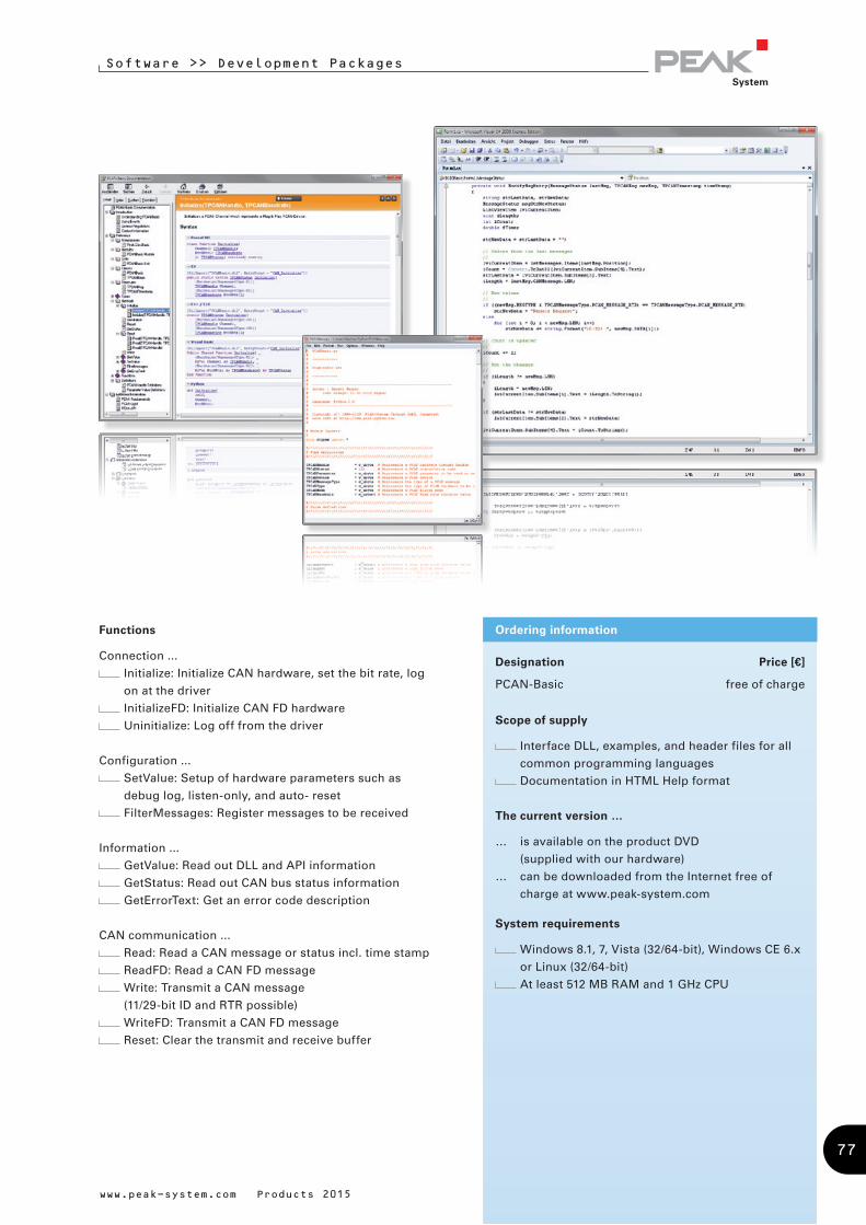
Software >> Development Packages
Designation Price [€]
PCAN-Basic free of charge
Scope of supply
Interface DLL, examples, and header files for all
common programming languages
Documentation in HTML Help format
The current version …
… is available on the product DVD
(supplied with our hardware)
… can be downloaded from the Internet free of
charge at www.peak-system.com
System requirements
Windows 8.1, 7, Vista (32/64-bit), Windows CE 6.x
or Linux (32/64-bit)
At least 512 MB RAM and 1 GHz CPU
Ordering information
www.peak-system.com Products 2015
Functions
Connection ...
Initialize: Initialize CAN hardware, set the bit rate, log
on at the driver
InitializeFD: Initialize CAN FD hardware
Uninitialize: Log off from the driver
Configuration ...
SetValue: Setup of hardware parameters such as
debug log, listen-only, and auto- reset
FilterMessages: Register messages to be received
Information ...
GetValue: Read out DLL and API information
GetStatus: Read out CAN bus status information
GetErrorText: Get an error code description
CAN communication ...
Read: Read a CAN message or status incl. time stamp
ReadFD: Read a CAN FD message
Write: Transmit a CAN message
(11/29-bit ID and RTR possible)
WriteFD: Transmit a CAN FD message
Reset: Clear the transmit and receive buffer
77

Software >> Development Packages
www.peak-system.com Products 2015
PCAN-CCP API & PCAN-XCP APIAPIs for the Communication with Control Units
The PCAN-CCP API is a programming interface for the
communication between Windows applications (Masters)
and electronic control units (Slave ECUs). The API is based
on the CAN Calibration Protocol (CCP) by ASAM and is
mainly deployed for development in the automotive area.
The Universal Measurement and Calibration Protocol
(XCP) is a further development of CCP, but not compatible.
XCP supports multiple transmission mediums. The
corresponding programming interface by PEAK-System
is called PCAN-XCP API which uses the CAN bus as
transmission medium analogous to the PCAN-CCP API.
Both APIs utilize the programming interface PCAN-Basic
for accessing the CAN hardware in the computer. PCAN-
Basic is included with every CAN interface from PEAK-
System. The PCAN-CCP API and PCAN-XCP API packages
are available free of charge.
Designation Price [€]
PCAN-CCP API free of charge
PCAN-XCP API free of charge
Scope of supply
Interface DLL, examples, and header files for all
common programming languages
Documentation in PDF format
Documentation in HTML Help format
The current version …
… is available on the product DVD
(supplied with our hardware)
… can be downloaded from the Internet free of
charge at www.peak-system.com
System requirements
Windows 8.1, 7, Vista (32/64-bit)
At least 512 MB RAM and 1 GHz CPU
PC CAN interface from PEAK-System
PCAN-Basic API
Ordering informationFeatures
Windows DLLs for the development of 32-bit and
64-bit applications
Physical communication via CAN using a CAN
interface of the PCAN series
Uses the PCAN-Basic programming interface to
access the CAN hardware in the computer
Thread-safe API
One API function for each command of the CCP/XCP
standards
Additional commands for communication
management
78

www.peak-system.com Products 2015
Software >> Development Packages
PCAN-ISO-TP APIAPI Implementation of the ISO-TP Standard (ISO 15765-2)
ISO-TP (ISO 15765-2) is an international standard for
the transfer of data packages via CAN. Above CAN (OSI
layers 1 and 2), the protocol covers the OSI layers 3
(Network Layer) and 4 (Transport Layer). It can transmit
data packages of up to 4095 Bytes per CAN message. The
data bytes are transmitted segmented with multiple CAN
frames.
The PCAN-ISO-TP API implements the functionality
of the standard on the basis of 10 functions. They are
categorized in Allocation, Configuration, Address Mapping
Configuration, Information, and Communication.
PCAN-ISO-TP uses the PCAN-Basic programming interface
to access the CAN hardware in the computer. PCAN-Basic
is supplied with each CAN interface of PEAK-System.
Designation Price [€]
PCAN-ISO-TP API free of charge
Scope of supply
Interface DLL, examples, and header files for all
common programming languages
Documentation in PDF format
Documentation in HTML Help format
The current version …
… is available on the product DVD
(supplied with our hardware)
… can be downloaded from the Internet free of
charge at www.peak-system.com
System requirements
Windows 8.1, 7, Vista (32/64-bit)
At least 512 MB RAM and 1 GHz CPU
PC CAN interface from PEAK-System
PCAN-Basic API
Ordering informationFeatures
Implementation of the ISO-TP protocol (ISO 15765-2)
for the transfer of data packages up to 4095 Bytes via
the CAN bus
Windows DLLs for the development of 32-bit and
64-bit applications
Physical communication via CAN using a CAN
interface of the PCAN series
Uses the PCAN-Basic programming interface to
access the CAN hardware in the computer
79
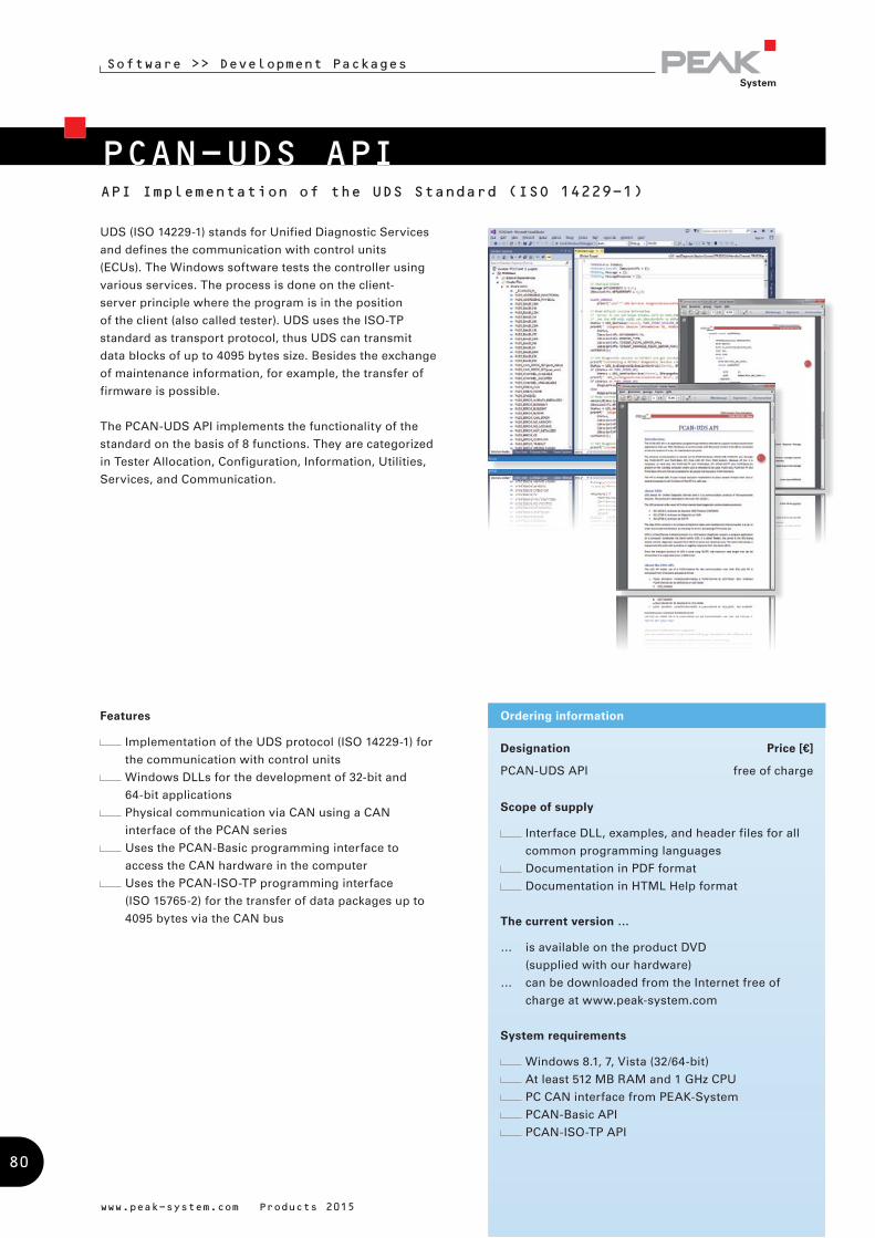
Software >> Development Packages
www.peak-system.com Products 2015
PCAN-UDS API
Designation Price [€]
PCAN-UDS API free of charge
Scope of supply
Interface DLL, examples, and header files for all
common programming languages
Documentation in PDF format
Documentation in HTML Help format
The current version …
… is available on the product DVD
(supplied with our hardware)
… can be downloaded from the Internet free of
charge at www.peak-system.com
System requirements
Windows 8.1, 7, Vista (32/64-bit)
At least 512 MB RAM and 1 GHz CPU
PC CAN interface from PEAK-System
PCAN-Basic API
PCAN-ISO-TP API
Ordering informationFeatures
Implementation of the UDS protocol (ISO 14229-1) for
the communication with control units
Windows DLLs for the development of 32-bit and
64-bit applications
Physical communication via CAN using a CAN
interface of the PCAN series
Uses the PCAN-Basic programming interface to
access the CAN hardware in the computer
Uses the PCAN-ISO-TP programming interface
(ISO 15765-2) for the transfer of data packages up to
4095 bytes via the CAN bus
API Implementation of the UDS Standard (ISO 14229-1)
UDS (ISO 14229-1) stands for Unified Diagnostic Services
and defines the communication with control units
(ECUs). The Windows software tests the controller using
various services. The process is done on the client-
server principle where the program is in the position
of the client (also called tester). UDS uses the ISO-TP
standard as transport protocol, thus UDS can transmit
data blocks of up to 4095 bytes size. Besides the exchange
of maintenance information, for example, the transfer of
firmware is possible.
The PCAN-UDS API implements the functionality of the
standard on the basis of 8 functions. They are categorized
in Tester Allocation, Configuration, Information, Utilities,
Services, and Communication.
80
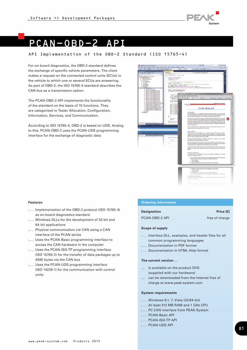
www.peak-system.com Products 2015
Software >> Development Packages
PCAN-OBD-2 APIAPI Implementation of the OBD-2 Standard (ISO 15765-4)
Designation Price [€]
PCAN-OBD-2 API free of charge
Scope of supply
Interface DLL, examples, and header files for all
common programming languages
Documentation in PDF format
Documentation in HTML Help format
The current version …
… is available on the product DVD
(supplied with our hardware)
… can be downloaded from the Internet free of
charge at www.peak-system.com
System requirements
Windows 8.1, 7, Vista (32/64-bit)
At least 512 MB RAM and 1 GHz CPU
PC CAN interface from PEAK-System
PCAN-Basic API
PCAN-ISO-TP API
PCAN-UDS API
Ordering informationFeatures
Implementation of the OBD-2 protocol (ISO 15765-4)
as on-board diagnostics standard
Windows DLLs for the development of 32-bit and
64-bit applications
Physical communication via CAN using a CAN
interface of the PCAN series
Uses the PCAN-Basic programming interface to
access the CAN hardware in the computer
Uses the PCAN-ISO-TP programming interface
(ISO 15765-2) for the transfer of data packages up to
4095 bytes via the CAN bus
Uses the PCAN-UDS programming interface
(ISO 14229-1) for the communication with control
units
For on-board diagnostics, the OBD-2 standard defines
the exchange of specific vehicle parameters. The client
makes a request on the connected control units (ECUs) in
the vehicle to which one or several ECUs are answering.
As part of OBD-2, the ISO 15765-4 standard describes the
CAN bus as a transmission option.
The PCAN-OBD-2 API implements the functionality
of the standard on the basis of 15 functions. They
are categorized in Tester Allocation, Configuration,
Information, Services, and Communication.
According to ISO 15765-4, OBD-2 is based on UDS. Analog
to this, PCAN-OBD-2 uses the PCAN-UDS programming
interface for the exchange of diagnostic data.
81
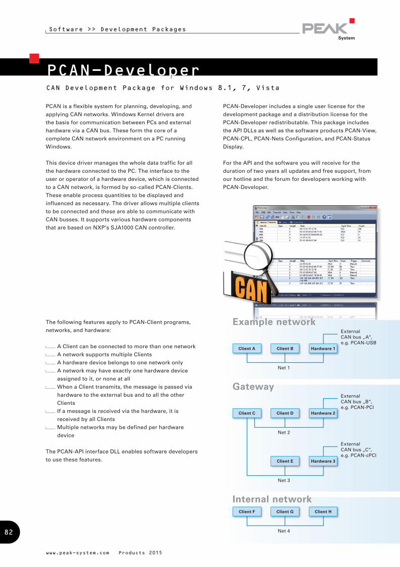
PCAN-DeveloperCAN Development Package for Windows 8.1, 7, Vista
Software >> Development Packages
www.peak-system.com Products 2015
PCAN is a flexible system for planning, developing, and
applying CAN networks. Windows Kernel drivers are
the basis for communication between PCs and external
hardware via a CAN bus. These form the core of a
complete CAN network environment on a PC running
Windows.
This device driver manages the whole data traffic for all
the hardware connected to the PC. The interface to the
user or operator of a hardware device, which is connected
to a CAN network, is formed by so-called PCAN-Clients.
These enable process quantities to be displayed and
influenced as necessary. The driver allows multiple clients
to be connected and these are able to communicate with
CAN busses. It supports various hardware components
that are based on NXP’s SJA1000 CAN controller.
The following features apply to PCAN-Client programs,
networks, and hardware:
A Client can be connected to more than one network
A network supports multiple Clients
A hardware device belongs to one network only
A network may have exactly one hardware device
assigned to it, or none at all
When a Client transmits, the message is passed via
hardware to the external bus and to all the other
Clients
If a message is received via the hardware, it is
received by all Clients
Multiple networks may be defined per hardware
device
The PCAN-API interface DLL enables software developers
to use these features.
PCAN-Developer includes a single user license for the
development package and a distribution license for the
PCAN-Developer redistributable. This package includes
the API DLLs as well as the software products PCAN-View,
PCAN-CPL, PCAN-Nets Configuration, and PCAN-Status
Display.
For the API and the software you will receive for the
duration of two years all updates and free support, from
our hotline and the forum for developers working with
PCAN-Developer.
Net 1
External CAN bus „A“, e.g. PCAN-USB
Client A Client B Hardware 1
Example network
Net 4
Client F Client G Client H
Internal network
Net 2
External CAN bus „B“, e.g. PCAN-PCI
Client C Client D Hardware 2
Net 3
External CAN bus „C“, e.g. PCAN-cPCI
Client E Hardware 3
Gateway
82

Software >> Development Packages
Designation Part No.
PCAN-Developer IPES-002070
Scope of supply
PCAN-API
PCAN-Developer license package
Software: PCAN-View, PCAN-CPL, PCAN-Nets
Configuration, and PCAN-Status Display
Header files, units, and examples
Documentation in HTML Help format
System requirements
Windows 8.1, 7, Vista (32/64-bit)
At least 512 MB RAM and 1 GHz CPU
Note: Parallel port CAN interfaces only support 32-bit.
Ordering information
www.peak-system.com Products 2015
Control of the transmission timing by specifying time
stamps when transmitting messages
Comprehensive programming manual (HTML Help
format) and runnable sample source code
Collection of tools for CAN system configuration,
parameterization, and visualization
Features
Supports the operating systems Windows 8.1, 7, Vista
(32/64-bit)
Use of a Windows DLL for 32-bit or 64-bit as
programming interface (API) for all supported
hardware types
Up to 32 applications can be operated per physical
CAN channel at the same time
Use of up to 16 channels for each hardware unit
Driver-internal buffering of 32,768 messages per
Client. Buffer size can be configured via the API
Precision of time stamps on received messages up to
1 µs (depending on the PEAK CAN interface used)
Hardware configuration using the control panel or
application
Simulated CAN communication between applications
via Clients
Configuration of single-shot and self-receive-request
transmissions
Access to all available hardware parameters such as
listen-only mode
Interrupt-driven reception of CAN messages from
the hardware into a FIFO buffer within the driver,
complete with time stamp
Notification of the application through Windows
events when a message is received
Supports CAN specifications 2.0A (11-bit ID) and 2.0B
(29-bit ID)
83

www.peak-system.com Products 2015
Designation Part No.
PCAN-RP1210 API IPES-002099
PCAN-Developer RP1210-Extension IPES-002099-FL
Scope of supply PCAN-RP1210 API
PCAN-RP1210 API
PCAN-Nets Configuration
PCAN-CPL
Documentation in PDF format
Documentation in HTML Help format
Scope of supply PCAN-Developer RP1210 Extension
PCAN-RP1210 API
Enhanced PCAN-Developer
redistributable package
PCAN-Nets Configuration
Documentation in PDF format
Documentation in HTML Help format
System requirements
Windows 8.1, 7, Vista (32/64-bit)
At least 512 MB RAM and 1 GHz CPU
Ordering information
PCAN-RP1210 APIRP1210 Development Package and RP1210 Connectivity to PEAK CAN Interfaces
Software >> Development Packages
Features
RP1210 (Version A and C) implementation according
to the specification by TMC
Development of own RP1210 applications
Use of RP1210 applications with PEAK CAN interfaces
Support of CAN and SAE J1939 networks
Note: The PCAN-Developer RP1210 Extension is only
available in conjunction with a valid PCAN-Developer
license.
The Recommended Practice 1210 was defined by
the Technology and Maintenance Council (TMC) as a
standardized API for communication between Windows
applications and communication networks in vehicles.
The PCAN-RP1210 API by PEAK-System is an
implementation of the RP1210 versions A and C with
support for CAN and SAE J1939 networks. Thus the API
makes it possible to develop own RP1210 applications and
to use already existing ones with CAN interfaces by PEAK-
System.
With the PCAN-RP1210 API you get a single user license
for the development package and for the RP1210
connectivity to PEAK CAN interfaces. The PCAN-
Developer RP1210 Extension contains a distribution
license for the PCAN-RP1210 API DLLs. With this extension
your customers can install the DLLs via the PCAN-
Developer redistributable package.
84
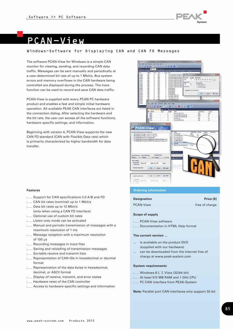
PCAN-ViewWindows-Software for Displaying CAN and CAN FD Messages
Software >> PC Software
Designation Price [€]
PCAN-View free of charge
Scope of supply
PCAN-View software
Documentation in HTML Help format
The current version …
… is available on the product DVD
(supplied with our hardware)
… can be downloaded from the Internet free of
charge at www.peak-system.com
System requirements
Windows 8.1, 7, Vista (32/64-bit)
At least 512 MB RAM and 1 GHz CPU
PC CAN interface from PEAK-System
Note: Parallel port CAN interfaces only support 32-bit
Ordering information
www.peak-system.com Products 2015
The software PCAN-View for Windows is a simple CAN
monitor for viewing, sending, and recording CAN data
traffic. Messages can be sent manually and periodically at
a user-determined bit rate of up to 1 Mbit/s. Bus system
errors and memory overflows in the CAN hardware being
controlled are displayed during the process. The trace
function can be used to record and save CAN data traffic.
PCAN-View is supplied with every PCAN PC hardware
product and enables a fast and simple initial hardware
operation. All available PEAK CAN interfaces are listed in
the connection dialog. After selecting the hardware and
the bit rate, the user can access all the software functions,
hardware-specific settings, and information.
Beginning with version 4, PCAN-View supports the new
CAN FD standard (CAN with Flexible Data rate) which
is primarily characterized by higher bandwidth for data
transfer.
Features
Support for CAN specifications 2.0 A/B and FD
CAN bit rates (nominal) up to 1 Mbit/s
Data bit rates up to 12 Mbit/s
(only when using a CAN FD interface)
Optional use of custom bit rates
Listen-only mode can be activated
Manual and periodic transmission of messages with a
maximum resolution of 1 ms
Message reception with a maximum resolution
of 100 µs
Recording messages in trace files
Saving and reloading of transmission messages
Sortable receive and transmit lists
Representation of CAN-IDs in hexadecimal or decimal
format
Representation of the data bytes in hexadecimal,
decimal, or ASCII format
Display of receive, transmit, and error states
Hardware reset of the CAN controller
Access to hardware-specific settings and information
85
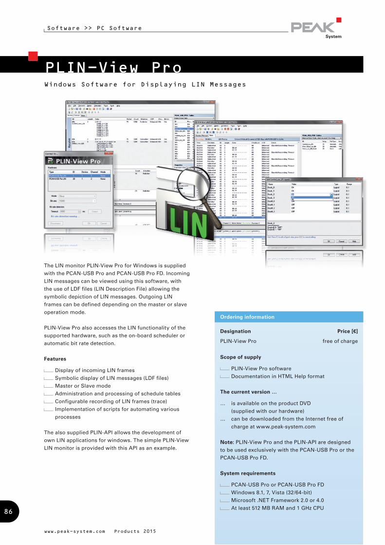
PLIN-View ProWindows Software for Displaying LIN Messages
Software >> PC Software
Designation Price [€]
PLIN-View Pro free of charge
Scope of supply
PLIN-View Pro software
Documentation in HTML Help format
The current version …
… is available on the product DVD
(supplied with our hardware)
… can be downloaded from the Internet free of
charge at www.peak-system.com
Note: PLIN-View Pro and the PLIN-API are designed
to be used exclusively with the PCAN-USB Pro or the
PCAN-USB Pro FD.
System requirements
PCAN-USB Pro or PCAN-USB Pro FD
Windows 8.1, 7, Vista (32/64-bit)
Microsoft .NET Framework 2.0 or 4.0
At least 512 MB RAM and 1 GHz CPU
Ordering information
www.peak-system.com Products 2015
The LIN monitor PLIN-View Pro for Windows is supplied
with the PCAN-USB Pro and PCAN-USB Pro FD. Incoming
LIN messages can be viewed using this software, with
the use of LDF files (LIN Description File) allowing the
symbolic depiction of LIN messages. Outgoing LIN
frames can be defined depending on the master or slave
operation mode.
PLIN-View Pro also accesses the LIN functionality of the
supported hardware, such as the on-board scheduler or
automatic bit rate detection.
Features
Display of incoming LIN frames
Symbolic display of LIN messages (LDF files)
Master or Slave mode
Administration and processing of schedule tables
Configurable recording of LIN frames (trace)
Implementation of scripts for automating various
processes
The also supplied PLIN-API allows the development of
own LIN applications for windows. The simple PLIN-View
LIN monitor is provided with this API as an example.
86
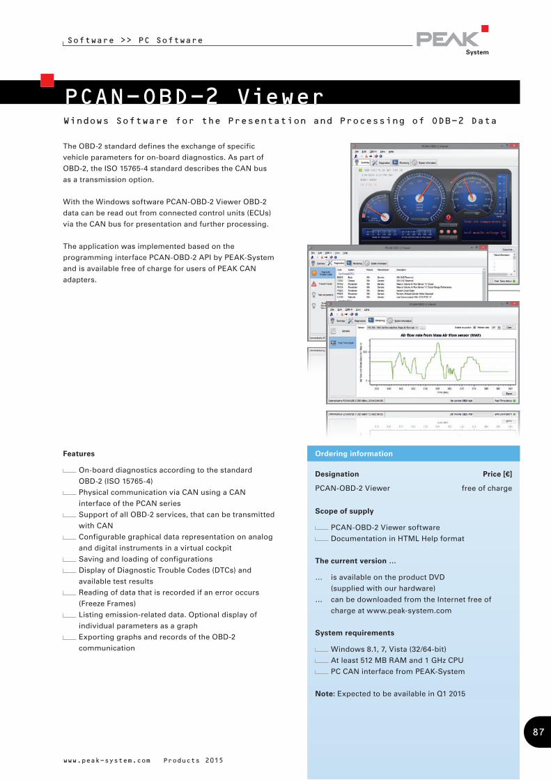
PCAN-OBD-2 Viewer
Software >> PC Software
www.peak-system.com Products 2015
Designation Price [€]
PCAN-OBD-2 Viewer free of charge
Scope of supply
PCAN-OBD-2 Viewer software
Documentation in HTML Help format
The current version …
… is available on the product DVD
(supplied with our hardware)
… can be downloaded from the Internet free of
charge at www.peak-system.com
System requirements
Windows 8.1, 7, Vista (32/64-bit)
At least 512 MB RAM and 1 GHz CPU
PC CAN interface from PEAK-System
Note: Expected to be available in Q1 2015
Ordering information
The OBD-2 standard defines the exchange of specific
vehicle parameters for on-board diagnostics. As part of
OBD-2, the ISO 15765-4 standard describes the CAN bus
as a transmission option.
With the Windows software PCAN-OBD-2 Viewer OBD-2
data can be read out from connected control units (ECUs)
via the CAN bus for presentation and further processing.
The application was implemented based on the
programming interface PCAN-OBD-2 API by PEAK-System
and is available free of charge for users of PEAK CAN
adapters.
Windows Software for the Presentation and Processing of ODB-2 Data
Features
On-board diagnostics according to the standard
OBD-2 (ISO 15765-4)
Physical communication via CAN using a CAN
interface of the PCAN series
Support of all OBD-2 services, that can be transmitted
with CAN
Configurable graphical data representation on analog
and digital instruments in a virtual cockpit
Saving and loading of configurations
Display of Diagnostic Trouble Codes (DTCs) and
available test results
Reading of data that is recorded if an error occurs
(Freeze Frames)
Listing emission-related data. Optional display of
individual parameters as a graph
Exporting graphs and records of the OBD-2
communication
87

PCAN-MicroMod ConfigurationWindows Configuration Software for PCAN-MicroMod Products
Software >> PC Software
www.peak-system.com Products 2015
The PCAN-MicroMod Configuration software can be used
to configure all products based on the PCAN-MicroMod.
Specific configuration options are available for the PCAN-
MicroMod itself, the motherboards, and the Evaluation
board, depending on the hardware in use.
Configuration data is transmitted to the module via
CAN. Use of unique module IDs allows independent
configuration of multiple devices on a single CAN bus.
Designation Price [€]
PCAN-MicroMod Configuration free of charge
Scope of supply
PCAN-MicroMod Configuration software
Documentation in HTML Help format
The current version …
… is available on the product DVD
(supplied with our hardware)
… can be downloaded from the Internet free of
charge at www.peak-system.com
System requirements
Windows 8.1, 7, Vista (32/64-bit)
At least 512 MB RAM and 1 GHz CPU
Ordering informationFeatures
Product-specific configuration options:
Periodic and edge-triggered transmission of CAN
messages
Logical linking of digital inputs
Direct conversion from analog inputs to
CAN IDs
Analog values can be processed using characteristic
curves or hysteresis functions
Direct evaluation of rotary encoders
Configuration data transmitted via CAN
(PEAK CAN interface required)
Existing configurations can be read out via CAN for
further processing
88

PPCAN-Editor 2Comprehensive Configuration Software for I/O Modules
Software >> PC Software
www.peak-system.com Products 2015
Designation Price [€]
PPCAN-Editor 2 free of charge
Scope of supply
PPCAN-Editor 2 software
Documentation in HTML Help format
PDF function block reference guide
The current version …
… is available on the product DVD
(supplied with our hardware)
… can be downloaded from the Internet free of
charge at www.peak-system.com
System requirements
Windows 8.1, 7, Vista (32/64-bit)
At least 512 MB RAM and 1 GHz CPU
Ordering informationFeatures
Definition of event-triggered or periodic CAN
message transmission
Data manipulation via the basic scale and offset
functions
Various function blocks for processing of
measurement values such as hysteresis, characteristic
curves, mathematical calculation operations, and
logical links
Selective forwarding of CAN data via gateway
functions
Conditional execution of function blocks via
comparison functions
Module-specific parameter settings
Importing of PCAN-Symbol Editor symbol files for
convenient definition of incoming and outgoing CAN
messages
Configuration data transmitted via CAN
(PEAK CAN interface required)
PPCAN-Editor 2 software enables detailed configuration
of various I/O modules with CAN connections, such as
PCAN-MIO, PCAN-Router Pro, and MU-Thermocouple1
CAN.
This type of configuration process begins with the
definition of incoming and outgoing CAN messages. Then,
depending on the hardware, the user has a number of
different function blocks and other settings available for
processing CAN data traffic. Finally, the configuration data
is transmitted to the module using CAN. This step requires
a PEAK CAN interface.
89
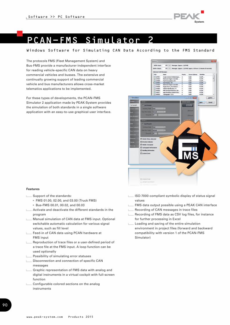
PCAN-FMS Simulator 2Windows Software for Simulating CAN Data According to the FMS Standard
Software >> PC Software
www.peak-system.com Products 2015
The protocols FMS (Fleet Management System) and
Bus-FMS provide a manufacturer-independent interface
for reading vehicle-specific CAN data on heavy
commercial vehicles and busses. The extensive and
continually growing support of leading commercial
vehicle and bus manufacturers allows cross-market
telematics applications to be implemented.
For these types of developments, the PCAN-FMS
Simulator 2 application made by PEAK-System provides
the simulation of both standards in a single software
application with an easy-to-use graphical user interface.
ISO-7000-compliant symbolic display of status signal
values
FMS data output possible using a PEAK CAN interface
Recording of CAN messages in trace files
Recording of FMS data as CSV log files, for instance
for further processing in Excel
Loading and saving of the entire simulation
environment in project files (forward and backward
compatibility with version 1 of the PCAN-FMS
Simulator)
Features
Support of the standards:
FMS 01.00, 02.00, and 03.00 (Truck FMS)
Bus-FMS 00.01, 00.02, and 00.03
Activate and deactivate the different standards in the
program
Manual simulation of CAN data at FMS input. Optional
switchable automatic calculation for various signal
values, such as fill level
Feed-in of CAN data using PCAN hardware at
FMS input
Reproduction of trace files or a user-defined period of
a trace file at the FMS input. A loop function can be
used optionally
Possibility of simulating error statuses
Disconnection and connection of specific CAN
messages
Graphic representation of FMS data with analog and
digital instruments in a virtual cockpit with full-screen
function
Configurable colored sections on the analog
instruments
90
Designation Part No.
PCAN-FMS Simulator 2 IPES-002050
Scope of supply
PCAN-FMS Simulator 2 installation CD
Portable license with USB copy protection dongle
Documentation in HTML Help format
(English and German)
System requirements
Windows 8.1, 7, Vista (32/64-bit)
Microsoft .NET Framework 2.0
At least 1 GB RAM and 1.6 GHz CPU
Free USB port for copy protection dongle
Ordering information
www.peak-system.com Products 2015
Software >> PC Software
Beginning with version 2.5, specially pre-configured
projects can be opened by the Tour Starter or directly with
desktop icons. This mode doesn‘t require further settings.
The display of the instruments is set to full-screen
mode and the tour recording can be started. Besides the
recording of trace and log data, additional information
is collected for later analysis, like fuel consumption and
average speed.
Features of the Tour mode:
Starting of specially pre-configured projects via the
Tour Starter or desktop icons for recurring analysis
and monitoring purposes
Recording of additional driving data, like fule
consumption and average speed
Archiving Tour-specific records and driving data
91

PCAN-TraceComprehensive Data Logger for CAN Messages
Software >> PC Software
Designation Part No.
PCAN-Trace IPES-002027
Scope of supply
PCAN-Trace installation CD
Single user license
Documentation in HTML help format
System requirements
Windows 8.1, 7, Vista (32/64-bit)
At least 512 MB RAM and 1 GHz CPU
Ordering information
The PCAN-Trace program is a data logger for up to
9,999,000 CAN messages. It enables CAN messages to
be quickly recorded, saved, and even played back on the
CAN bus. The program displays the number of received
messages and identifies the types of the messages (data
frame, error frame, RTR frame).
CAN messages can be recorded or replayed in linear or
ring buffer mode. PCAN-Trace also provides an option to
play back CAN messages in single step mode. You can
also simplify analysis and tracing by setting playback
mode breakpoints.
www.peak-system.com Products 2015
Features
Log facility for up to 9,999,000 CAN messages
Choice of linear buffer or ring buffer (in receive and
playback mode)
Displays number and type of received CAN messages
Adjustable message filter
Support for 11-bit and 29-bit IDs
Facility to play back CAN messages that have been
recorded using PCAN-Explorer or PCAN-View, even in
single-step mode
Playback of selected areas of a CAN message record
Breakpoints can be used in playback mode
Received data can also be viewed in a text editor
Control of the software via the command line
92
PCAN-Explorer 5 Comprehensive CAN Monitor for Windows
Software >> PC Software
PCAN-Explorer is a universal tool for monitoring data
traffic on a CAN network. For easy and clear allocation
of the individual messages, these can be identified as
so-called symbols. The integrated VBScript support allows
the creation of macros to automate complex tasks. The
integrated data logger means that the data traffic of a bus
can be recorded, analyzed, and stored. PCAN-Explorer
is designed as automation server and can therefore be
remote controlled through scripts.
Features
All files and elements can be managed and saved in
projects
Project components such as CAN connections,
symbol files, and macros are clearly displayed and
laid out in the project browser
The new start page allows fast access to the most
recently opened projects or files
Simultaneous connections with up to 16 networks/
CAN interfaces of the same hardware type
Connection window with an overview of all
connections, complete with status, error counters,
bus load, etc.
All parameters of all elements in the user interface
can be examined using a property window and edited
if necessary
Multiple flexible filters can be configured and, for
example, assigned to the transmit/receive window or
the various different tracers
Tabs to switch between the different windows
Flexible arrangement of the user interface using the
dockable windows
User-defined column display and arrangement in
transmit/receive window
J1939 support with the relevant add-in
Display of received messages showing the ID, length,
data bytes, number of messages received, and
receiving interval
Simultaneous hexadecimal and symbolic
representation of the details
Display of remote frames, status reports of the CAN
controller and, as an option, CAN bus error frames
Logging of time-outs
www.peak-system.com Products 2015
93

Software >> PC Software
www.peak-system.com Products 2015
Transmission of messages at fixed intervals of time,
manually or as reply to remote frames
Messages can be created as transmit lists, stored
and loaded as desired, in order to e. g. emulate CAN
nodes
Periodical transmission with up to 1 ms precision
Easy creation of symbol files and macros using the
integrated text editor with syntax highlighting
User-friendly real-time monitoring of several signals
via the watch window
Extensive improvements to user guidance and
interface compared to PCAN-Explorer version 4
User interface language can be switched
(German/English)
Simple integration of external tools
Integration of add-ins to upgrade functionality
Function upgrade of the PCAN-Explorer with the
integrated VBScript language:
Creation of macros in VBScript with the integrated
text editor
Access with macros and scripts to almost all program
elements via the PCAN-Explorer object model
Ideal for creating test tools to implement or develop
CAN systems
Examples: sending of e-mails when a temperature
is exceeded, starting of a test tool when a particular
message is received, opening of an Excel sheet when
an event occurs and saving of data in the individual
cells
Assignment of function keys with individual send
messages or macros
VBS scripts run in the background even without the
PCAN-Explorer interface
94
Properties of the integrated, configurable PCAN-Explorer
data logger:
Operation of multiple tracers at the same time
Variable buffer size
Optional linear buffer or circular buffer
Representation of the logged messages with time
stamp, type, ID, length, and data bytes
Logging of errors that have occurred is possible
Flexible storage possibility for the logged data in text
form for importing into Excel or similar
Export of the recording to a CSV file
Filtering of the messages for logging through symbol
definitions
Subsequent examination of the logged data in the
buffer via different symbol files
PCAN Explorer 5 Training:
We offer a training session for the PCAN-Explorer, which
includes an introduction to the main features of the
software, the work with the PCAN-Symbol Editor, and a
demonstration of the add-ins. If you are interested and for
further information, please contact
www.peak-system.com Products 2015
Software >> PC Software
Designation Part No.
PCAN-Explorer 5
Single Computer License
IPES-005028
PCAN-Explorer 5
Portable License +
Copy Protection Dongle
IPES-005028
+ IPES-005090
Scope of supply
PCAN-Explorer installation CD including
PCAN-Explorer Line Writer Add-in
Single computer license or portable license with
USB copy protection dongle
PCAN-Symbol Editor for Windows
(details on page 100)
Documentation in HTML help format
System requirements
Windows 8.1, 7, Vista (32/64-bit)
At least 512 MB RAM and 1 GHz CPU
Free USB port for copy protection dongle
(only for portable license)
Ordering information
PCAN-Explorer 5 Licenses:
Single Computer License - With this license you get
an installation CD and a license file. With that you can
install, unlock, and use the software on a single computer
exclusively.
Portable License + USB Copy Protection Dongle - With this
type of license, you get an USB copy protection dongle for
each purchased license in addition to the installation CD.
You can install PCAN-Explorer 5 on several computers. In
order to unlock and use the software, you must plug the
copy protection dongle into a free USB port.
95
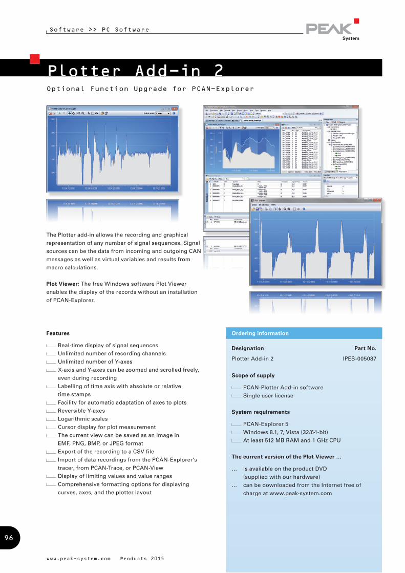
Plotter Add-in 2Optional Function Upgrade for PCAN-Explorer
Software >> PC Software
Designation Part No.
Plotter Add-in 2 IPES-005087
Scope of supply
PCAN-Plotter Add-in software
Single user license
System requirements
PCAN-Explorer 5
Windows 8.1, 7, Vista (32/64-bit)
At least 512 MB RAM and 1 GHz CPU
The current version of the Plot Viewer …
… is available on the product DVD
(supplied with our hardware)
… can be downloaded from the Internet free of
charge at www.peak-system.com
Ordering information
www.peak-system.com Products 2015
Features
Real-time display of signal sequences
Unlimited number of recording channels
Unlimited number of Y-axes
X-axis and Y-axes can be zoomed and scrolled freely,
even during recording
Labelling of time axis with absolute or relative
time stamps
Facility for automatic adaptation of axes to plots
Reversible Y-axes
Logarithmic scales
Cursor display for plot measurement
The current view can be saved as an image in
EMF, PNG, BMP, or JPEG format
Export of the recording to a CSV file
Import of data recordings from the PCAN-Explorer‘s
tracer, from PCAN-Trace, or PCAN-View
Display of limiting values and value ranges
Comprehensive formatting options for displaying
curves, axes, and the plotter layout
The Plotter add-in allows the recording and graphical
representation of any number of signal sequences. Signal
sources can be the data from incoming and outgoing CAN
messages as well as virtual variables and results from
macro calculations.
Plot Viewer: The free Windows software Plot Viewer
enables the display of the records without an installation
of PCAN-Explorer.
96

CANdb Import Add-in 3Optional Function Upgrade for PCAN-Explorer
Software >> PC Software
Designation Part No.
CANdb Import Add-in 3 IPES-005086
Scope of supply
CANdb Import Add-in software
Single user license
Documentation in HTML help format
System requirements
PCAN-Explorer 5
Windows 8.1, 7, Vista (32/64-bit)
At least 512 MB RAM and 1 GHz CPU
Ordering information
www.peak-system.com Products 2015
The CANdb format is a common data description format
for CAN bus information in the car industry.
CANdb Import allows the import of CANdb files. This is a
useful function for all those who do not want to manually
transcribe their database into the PCAN-Explorer symbol
format.
Features
Opening of CANdb files (.dbc)
Selecting of the messages for importing in a
CANdb file
Saves data using the project administration function
in PCAN-Explorer
Storing in the PCAN-Explorer symbol format
97
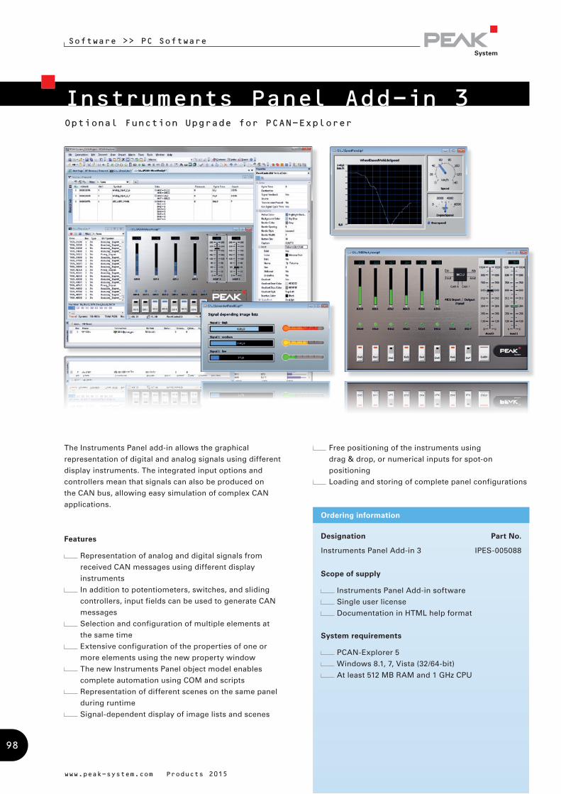
Instruments Panel Add-in 3Optional Function Upgrade for PCAN-Explorer
Software >> PC Software
www.peak-system.com Products 2015
Free positioning of the instruments using
drag & drop, or numerical inputs for spot-on
positioning
Loading and storing of complete panel configurations
Features
Representation of analog and digital signals from
received CAN messages using different display
instruments
In addition to potentiometers, switches, and sliding
controllers, input fields can be used to generate CAN
messages
Selection and configuration of multiple elements at
the same time
Extensive configuration of the properties of one or
more elements using the new property window
The new Instruments Panel object model enables
complete automation using COM and scripts
Representation of different scenes on the same panel
during runtime
Signal-dependent display of image lists and scenes
Designation Part No.
Instruments Panel Add-in 3 IPES-005088
Scope of supply
Instruments Panel Add-in software
Single user license
Documentation in HTML help format
System requirements
PCAN-Explorer 5
Windows 8.1, 7, Vista (32/64-bit)
At least 512 MB RAM and 1 GHz CPU
Ordering information
The Instruments Panel add-in allows the graphical
representation of digital and analog signals using different
display instruments. The integrated input options and
controllers mean that signals can also be produced on
the CAN bus, allowing easy simulation of complex CAN
applications.
98
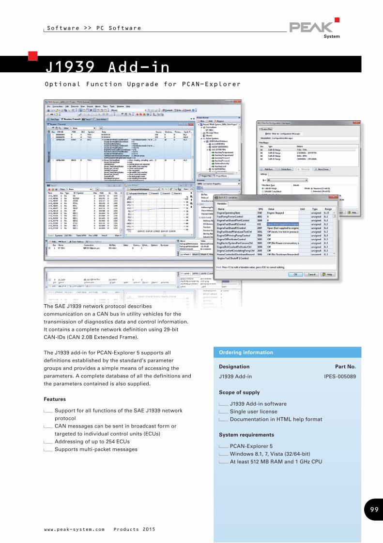
Software >> PC Software
Optional Function Upgrade for PCAN-Explorer
J1939 Add-in
Designation Part No.
J1939 Add-in IPES-005089
Scope of supply
J1939 Add-in software
Single user license
Documentation in HTML help format
System requirements
PCAN-Explorer 5
Windows 8.1, 7, Vista (32/64-bit)
At least 512 MB RAM and 1 GHz CPU
Ordering information
The SAE J1939 network protocol describes
communication on a CAN bus in utility vehicles for the
transmission of diagnostics data and control information.
It contains a complete network definition using 29-bit
CAN-IDs (CAN 2.0B Extended Frame).
The J1939 add-in for PCAN-Explorer 5 supports all
definitions established by the standard’s parameter
groups and provides a simple means of accessing the
parameters. A complete database of all the definitions and
the parameters contained is also supplied.
Features
Support for all functions of the SAE J1939 network
protocol
CAN messages can be sent in broadcast form or
targeted to individual control units (ECUs)
Addressing of up to 254 ECUs
Supports multi-packet messages
www.peak-system.com Products 2015
99
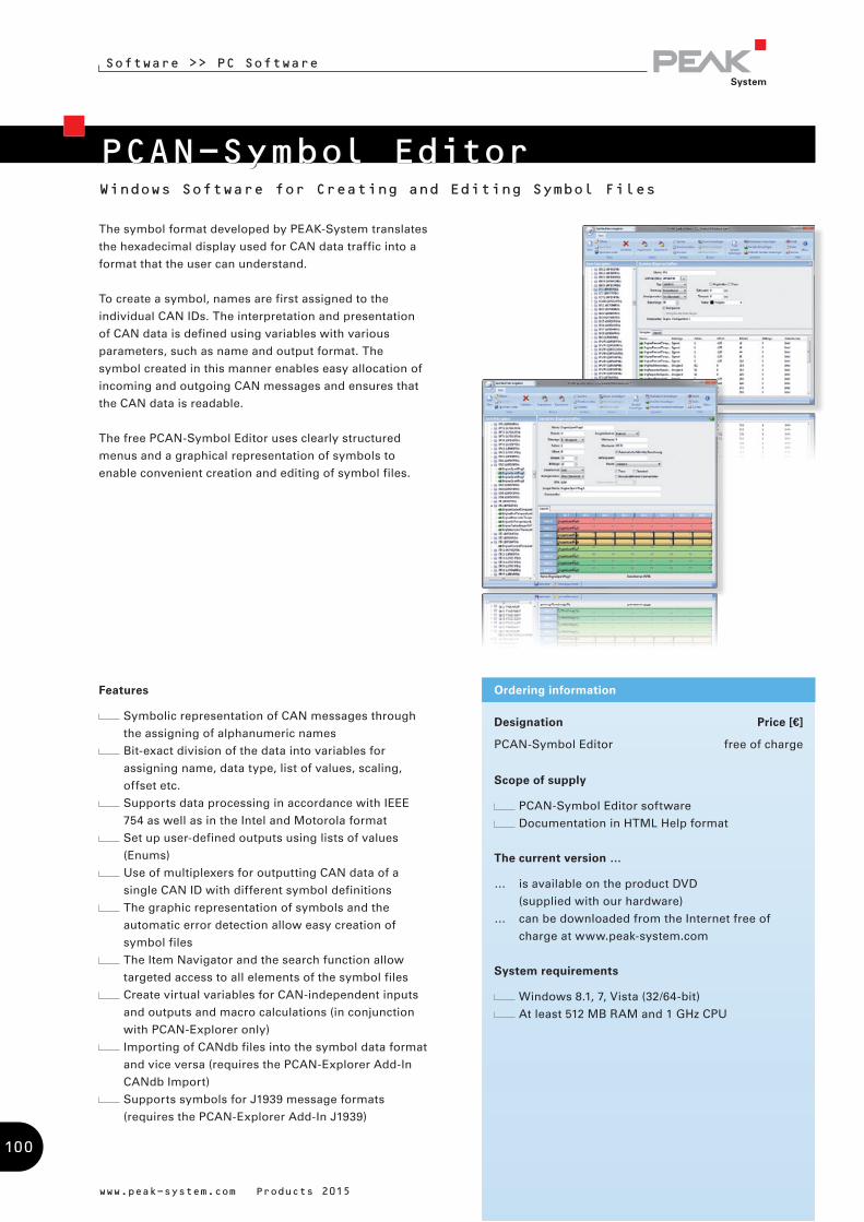
Software >> PC Software
Windows Software for Creating and Editing Symbol Files
PCAN-Symbol Editor
www.peak-system.com Products 2015
Designation Price [€]
PCAN-Symbol Editor free of charge
Scope of supply
PCAN-Symbol Editor software
Documentation in HTML Help format
The current version …
… is available on the product DVD
(supplied with our hardware)
… can be downloaded from the Internet free of
charge at www.peak-system.com
System requirements
Windows 8.1, 7, Vista (32/64-bit)
At least 512 MB RAM and 1 GHz CPU
Ordering information
The symbol format developed by PEAK-System translates
the hexadecimal display used for CAN data traffic into a
format that the user can understand.
To create a symbol, names are first assigned to the
individual CAN IDs. The interpretation and presentation
of CAN data is defined using variables with various
parameters, such as name and output format. The
symbol created in this manner enables easy allocation of
incoming and outgoing CAN messages and ensures that
the CAN data is readable.
The free PCAN-Symbol Editor uses clearly structured
menus and a graphical representation of symbols to
enable convenient creation and editing of symbol files.
Features
Symbolic representation of CAN messages through
the assigning of alphanumeric names
Bit-exact division of the data into variables for
assigning name, data type, list of values, scaling,
offset etc.
Supports data processing in accordance with IEEE
754 as well as in the Intel and Motorola format
Set up user-defined outputs using lists of values
(Enums)
Use of multiplexers for outputting CAN data of a
single CAN ID with different symbol definitions
The graphic representation of symbols and the
automatic error detection allow easy creation of
symbol files
The Item Navigator and the search function allow
targeted access to all elements of the symbol files
Create virtual variables for CAN-independent inputs
and outputs and macro calculations (in conjunction
with PCAN-Explorer only)
Importing of CANdb files into the symbol data format
and vice versa (requires the PCAN-Explorer Add-In
CANdb Import)
Supports symbols for J1939 message formats
(requires the PCAN-Explorer Add-In J1939)
100
Helpful CAN accessories
Ideal for test layouts and small batches
PC adapter cards for PC/104 Small Form Factor Boards
CAN cables and adapters for various applications
Special manufacture possible at any time
Adapters
Cables
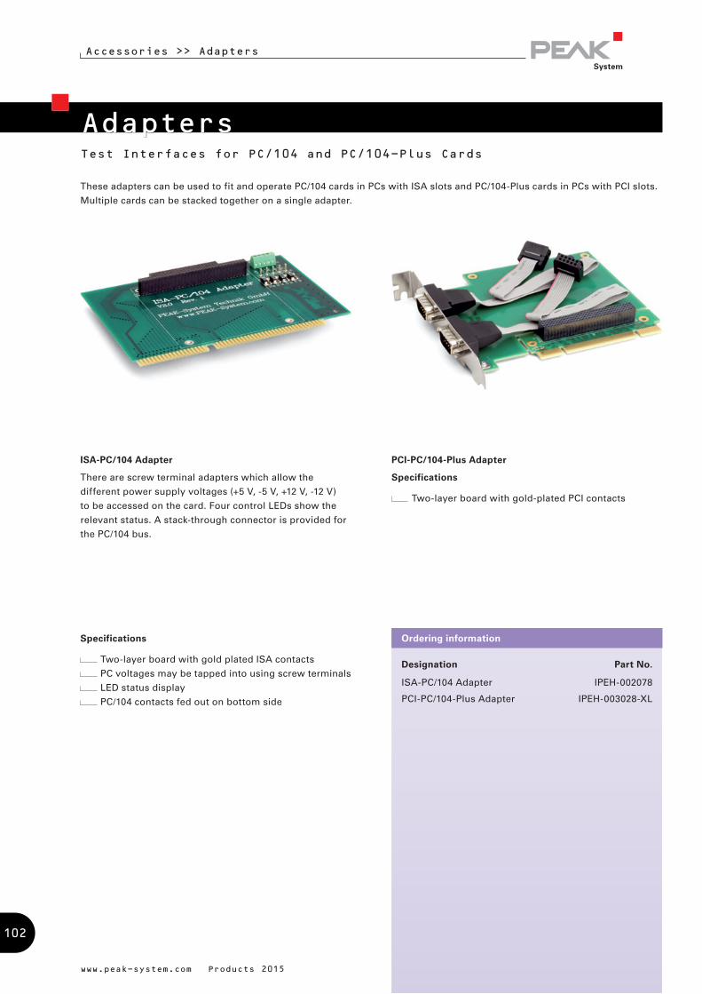
Test Interfaces for PC/104 and PC/104-Plus Cards
Accessories >> Adapters
Designation Part No.
ISA-PC/104 Adapter IPEH-002078
PCI-PC/104-Plus Adapter IPEH-003028-XL
Ordering information
www.peak-system.com Products 2015
Adapters
These adapters can be used to fit and operate PC/104 cards in PCs with ISA slots and PC/104-Plus cards in PCs with PCI slots.
Multiple cards can be stacked together on a single adapter.
ISA-PC/104 Adapter
There are screw terminal adapters which allow the
different power supply voltages (+5 V, -5 V, +12 V, -12 V)
to be accessed on the card. Four control LEDs show the
relevant status. A stack-through connector is provided for
the PC/104 bus.
PCI-PC/104-Plus Adapter
Specifications
Two-layer board with gold-plated PCI contacts
Specifications
Two-layer board with gold plated ISA contacts
PC voltages may be tapped into using screw terminals
LED status display
PC/104 contacts fed out on bottom side
102
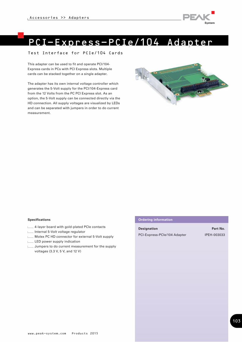
Test Interface for PCIe/104 Cards
Designation Part No.
PCI-Express-PCIe/104 Adapter IPEH-003033
Ordering information
PCI-Express-PCIe/104 Adapter
www.peak-system.com Products 2015
Accessories >> Adapters
This adapter can be used to fit and operate PCI/104-
Express cards in PCs with PCI Express slots. Multiple
cards can be stacked together on a single adapter.
The adapter has its own internal voltage controller which
generates the 5-Volt supply for the PCI/104-Express card
from the 12 Volts from the PC PCI Express slot. As an
option, the 5-Volt supply can be connected directly via the
HD connection. All supply voltages are visualized by LEDs
and can be separated with jumpers in order to do current
measurement.
Specifications
4-layer board with gold-plated PCIe contacts
Internal 5-Volt voltage regulator
Molex PC HD connector for external 5-Volt supply
LED power supply indication
Jumpers to do current measurement for the supply
voltages (3.3 V, 5 V, and 12 V)
103
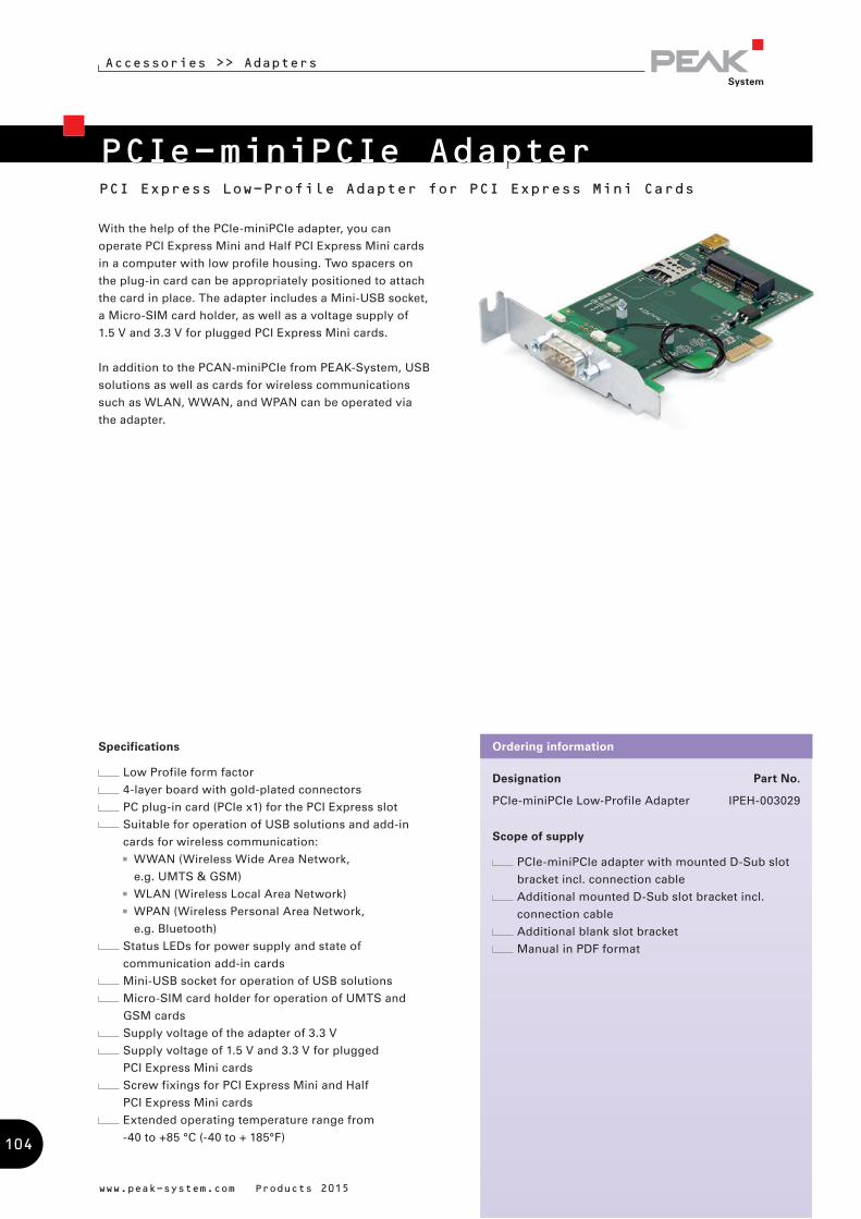
With the help of the PCIe-miniPCIe adapter, you can
operate PCI Express Mini and Half PCI Express Mini cards
in a computer with low profile housing. Two spacers on
the plug-in card can be appropriately positioned to attach
the card in place. The adapter includes a Mini-USB socket,
a Micro-SIM card holder, as well as a voltage supply of
1.5 V and 3.3 V for plugged PCI Express Mini cards.
In addition to the PCAN-miniPCIe from PEAK-System, USB
solutions as well as cards for wireless communications
such as WLAN, WWAN, and WPAN can be operated via
the adapter.
Designation Part No.
PCIe-miniPCIe Low-Profile Adapter IPEH-003029
Scope of supply
PCIe-miniPCIe adapter with mounted D-Sub slot
bracket incl. connection cable
Additional mounted D-Sub slot bracket incl.
connection cable
Additional blank slot bracket
Manual in PDF format
Ordering informationSpecifications
Low Profile form factor
4-layer board with gold-plated connectors
PC plug-in card (PCIe x1) for the PCI Express slot
Suitable for operation of USB solutions and add-in
cards for wireless communication:
WWAN (Wireless Wide Area Network,
e.g. UMTS & GSM)
WLAN (Wireless Local Area Network)
WPAN (Wireless Personal Area Network,
e.g. Bluetooth)
Status LEDs for power supply and state of
communication add-in cards
Mini-USB socket for operation of USB solutions
Micro-SIM card holder for operation of UMTS and
GSM cards
Supply voltage of the adapter of 3.3 V
Supply voltage of 1.5 V and 3.3 V for plugged
PCI Express Mini cards
Screw fixings for PCI Express Mini and Half
PCI Express Mini cards
Extended operating temperature range from
-40 to +85 °C (-40 to + 185°F)
PCIe-miniPCIe AdapterPCI Express Low-Profile Adapter for PCI Express Mini Cards
www.peak-system.com Products 2015
Accessories >> Adapters
104

Designation Part No.
PCAN-D-Sub Connection Adapter IPEK-003012
Ordering informationSpecifications
4-pin screw terminal block (Phoenix) to 9-pin D-Sub
socket (according to CiA® 102)
Suitable for CAN connection adaptation of the
products:
PCAN-Repeater DR
PCAN-Router DR
PCAN-Ethernet Gateway DR
PCAN-Wireless Gateway DR
No termination
PCAN-D-Sub Connection AdapterD-Sub Connection Adapter for Screw Terminal Blocks
www.peak-system.com Products 2015
Accessories >> Adapters
PEAK-System CAN hardware has a 4-pin screw terminal
block as CAN connector for models in the DIN rail
housing. The PCAN-D-Sub Connection Adapter provides a
9-pin D-Sub socket for the screw terminal pins. Thus, it is
possible to plug in our standard CAN cable and to connect
to our PC CAN interfaces.
105
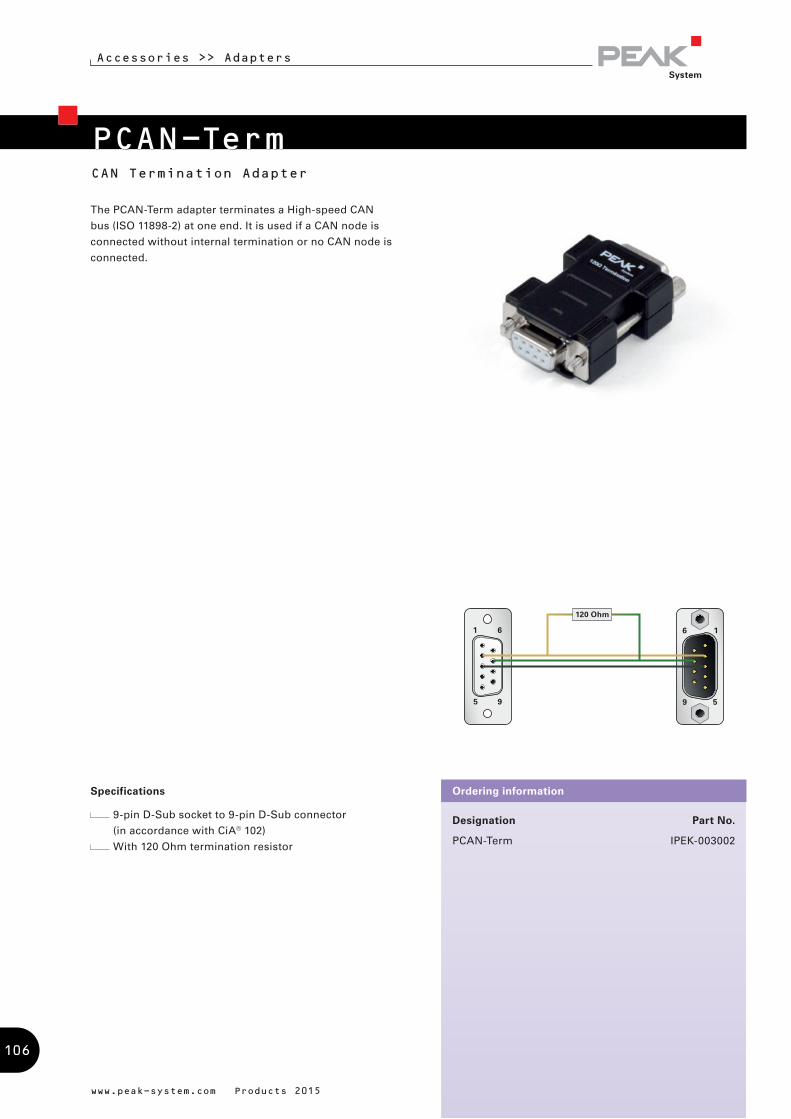
120 Ohm
www.peak-system.com Products 2015
The PCAN-Term adapter terminates a High-speed CAN
bus (ISO 11898-2) at one end. It is used if a CAN node is
connected without internal termination or no CAN node is
connected.
CAN Termination Adapter
Accessories >> Adapters
Designation Part No.
PCAN-Term IPEK-003002
Ordering informationSpecifications
9-pin D-Sub socket to 9-pin D-Sub connector
(in accordance with CiA® 102)
With 120 Ohm termination resistor
PCAN-Term
106

www.peak-system.com Products 2015
T-Adapter for CAN Tapping
Accessories >> Adapters
The PCAN-T-Adapter creates a tap connection to the data
cables and the ground within a CAN bus in order to be
able to connect a CAN node. In this case, the CAN node is
not terminated.
Designation Part No.
PCAN-T-Adapter IPEK-003003
Ordering informationSpecifications
9-pin D-Sub socket to 9-pin D-Sub connector and
D-Sub socket (in accordance with CiA® 102)
CAN tap length about 20 cm
No termination
PCAN-T-Adapter
107
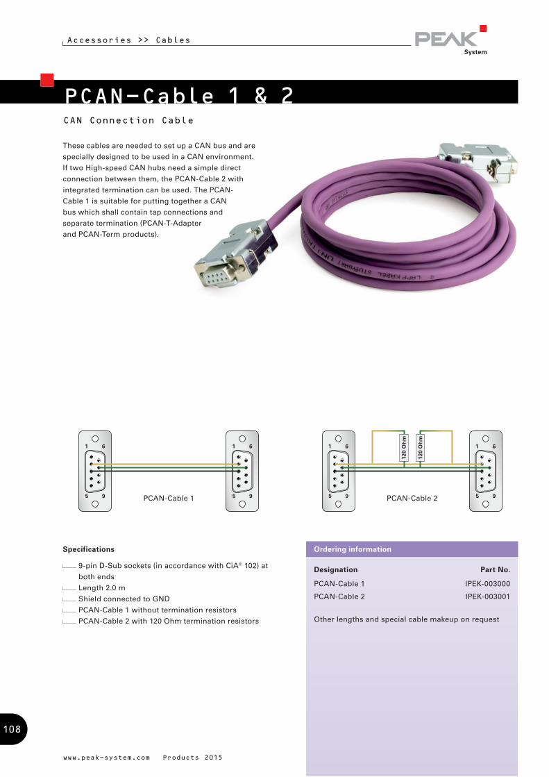
120
Oh
m
120
Oh
m
www.peak-system.com Products 2015
Specifications
9-pin D-Sub sockets (in accordance with CiA® 102) at
both ends
Length 2.0 m
Shield connected to GND
PCAN-Cable 1 without termination resistors
PCAN-Cable 2 with 120 Ohm termination resistors
Designation Part No.
PCAN-Cable 1 IPEK-003000
PCAN-Cable 2 IPEK-003001
Other lengths and special cable makeup on request
Ordering information
PCAN-Cable 1 & 2
Accessories >> Cables
These cables are needed to set up a CAN bus and are
specially designed to be used in a CAN environment.
If two High-speed CAN hubs need a simple direct
connection between them, the PCAN-Cable 2 with
integrated termination can be used. The PCAN-
Cable 1 is suitable for putting together a CAN
bus which shall contain tap connections and
separate termination (PCAN-T-Adapter
and PCAN-Term products).
CAN Connection Cable
PCAN-Cable 1 PCAN-Cable 2
108

CAN_L
CAN_H
With this cable the two components CAN-High and
CAN-Low of the differential CAN signal can be picked
up from a CAN bus or directly from a CAN interface.
An easy connection to test and measurement setups is
accomplished by the banana plugs.
www.peak-system.com Products 2015
Specifications
9-pin D-Sub socket (in accordance with CiA® 102)
to banana plugs 4 mm for picking up the signals
CAN-High and CAN-Low
Without termination resistors
Length 2.0 m
Designation Part No.
PCAN-Cable 3 IPEK-003011
Other lengths and special cable makeup on request
Ordering information
PCAN-Cable 3
Accessories >> Cables
CAN Cable for Test and Measurement Setups
109
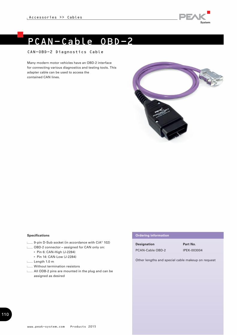
www.peak-system.com Products 2015
Designation Part No.
PCAN-Cable OBD-2 IPEK-003004
Other lengths and special cable makeup on request
Ordering informationSpecifications
9-pin D-Sub socket (in accordance with CiA® 102)
OBD-2 connector – assigned for CAN only on:
Pin 6: CAN-High (J-2284)
Pin 14: CAN-Low (J-2284)
Length 1.0 m
Without termination resistors
All ODB-2 pins are mounted in the plug and can be
assigned as desired
PCAN-Cable OBD-2
Accessories >> Cables
CAN-OBD-2 Diagnostics Cable
Many modern motor vehicles have an OBD-2 interface
for connecting various diagnostics and testing tools. This
adapter cable can be used to access the
contained CAN lines.
110
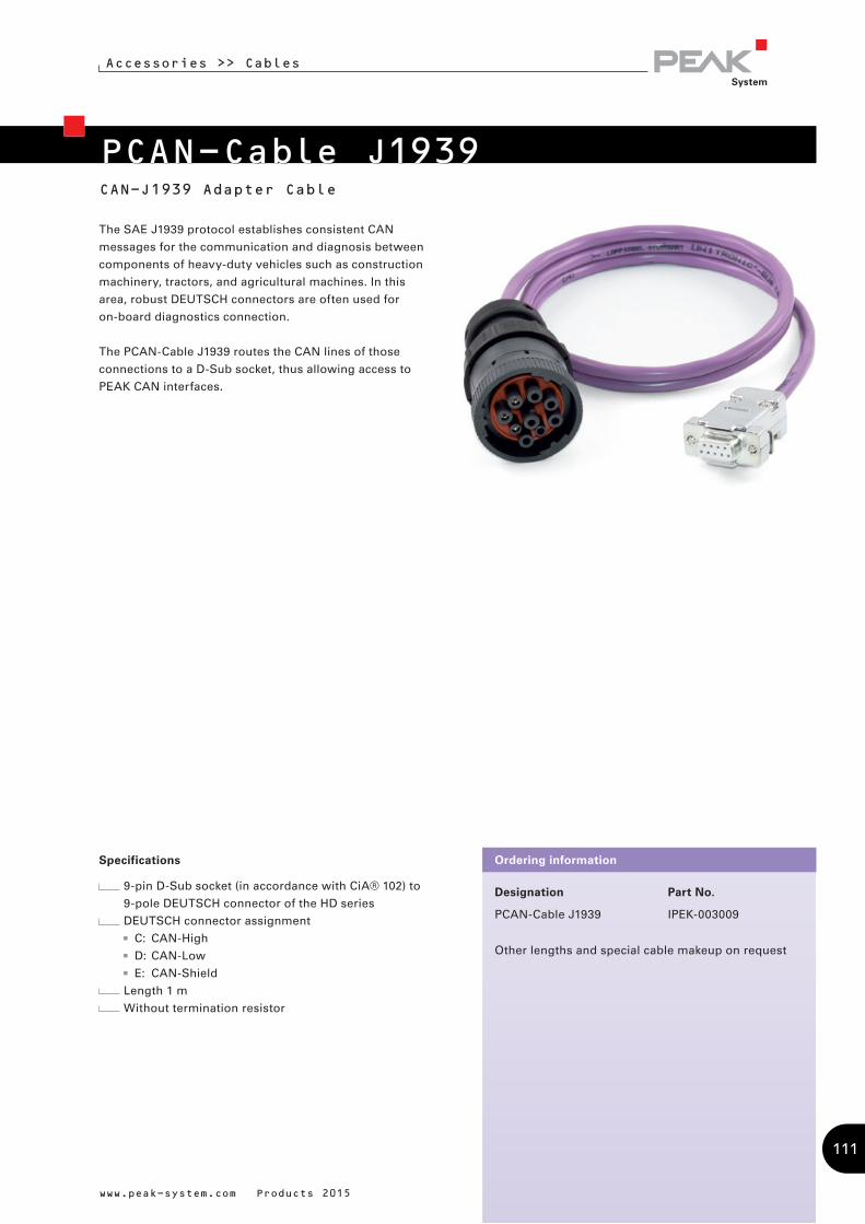
Designation Part No.
PCAN-Cable J1939 IPEK-003009
Other lengths and special cable makeup on request
Ordering information
PCAN-Cable J1939
The SAE J1939 protocol establishes consistent CAN
messages for the communication and diagnosis between
components of heavy-duty vehicles such as construction
machinery, tractors, and agricultural machines. In this
area, robust DEUTSCH connectors are often used for
on-board diagnostics connection.
The PCAN-Cable J1939 routes the CAN lines of those
connections to a D-Sub socket, thus allowing access to
PEAK CAN interfaces.
www.peak-system.com Products 2015
Accessories >> Cables
CAN-J1939 Adapter Cable
Specifications
9-pin D-Sub socket (in accordance with CiA® 102) to
9-pole DEUTSCH connector of the HD series
DEUTSCH connector assignment
C: CAN-High
D: CAN-Low
E: CAN-Shield
Length 1 m
Without termination resistor
111
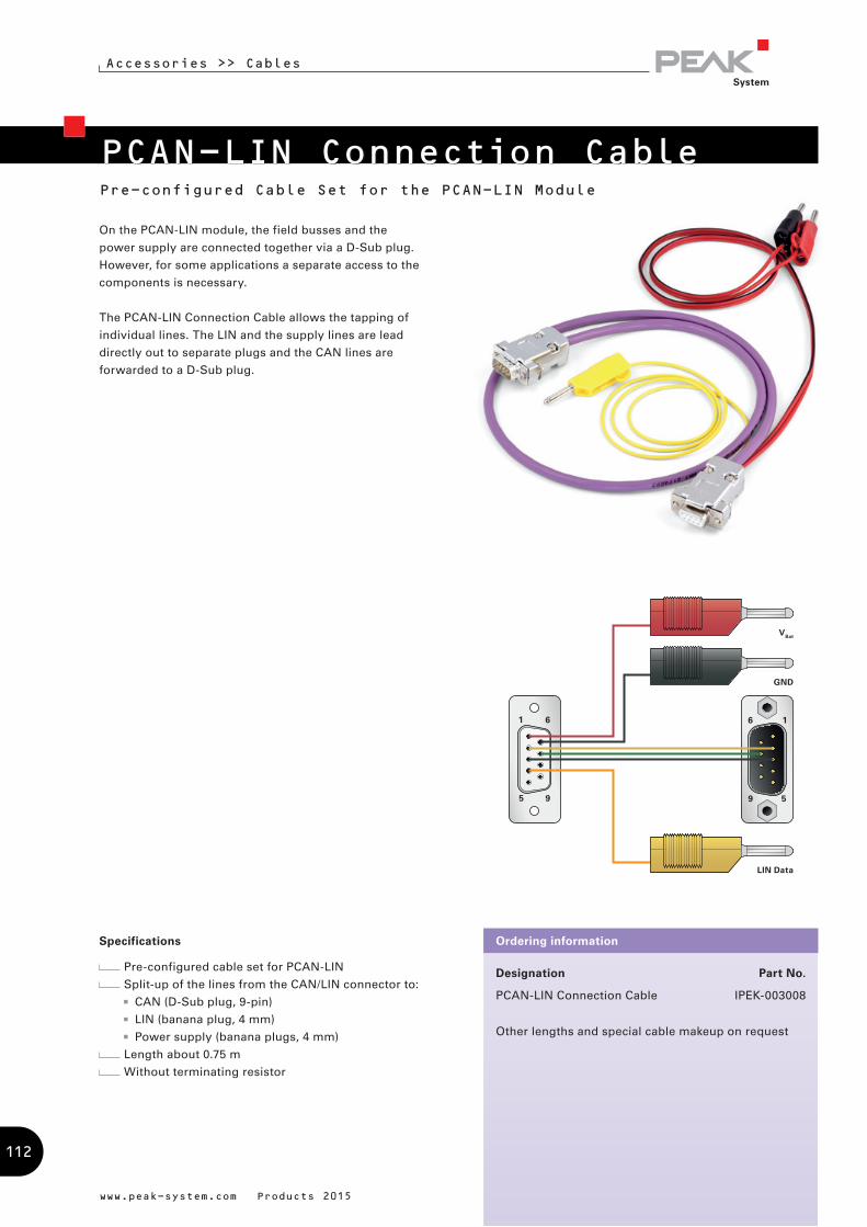
VBat
LIN Data
GND
On the PCAN-LIN module, the field busses and the
power supply are connected together via a D-Sub plug.
However, for some applications a separate access to the
components is necessary.
The PCAN-LIN Connection Cable allows the tapping of
individual lines. The LIN and the supply lines are lead
directly out to separate plugs and the CAN lines are
forwarded to a D-Sub plug.
www.peak-system.com Products 2015
Specifications
Pre-configured cable set for PCAN-LIN
Split-up of the lines from the CAN/LIN connector to:
CAN (D-Sub plug, 9-pin)
LIN (banana plug, 4 mm)
Power supply (banana plugs, 4 mm)
Length about 0.75 m
Without terminating resistor
Designation Part No.
PCAN-LIN Connection Cable IPEK-003008
Other lengths and special cable makeup on request
Ordering information
PCAN-LIN Connection Cable
Accessories >> Cables
Pre-configured Cable Set for the PCAN-LIN Module
112
PEAK-System Technik
PEAK-System
PEAK-System Technik GmbHGermany, Austria & Switzerland
Head Office Darmstadt
Otto-Röhm-Str. 69, 64293 Darmstadt
Germany
Phone: +49 6151 8173-20
Fax: +49 6151 8173-29
E-mail: [email protected]
Website: www.peak-system.com
PEAK-System S.A.R.L.France
132, rue André Bisiaux, bâtiment C 1er étage
54320 Maxeville
France
Phone: +33 (0)3.83.54.15.20
Fax: +33 (0)3.83.54.15.21
E-mail: [email protected]
Website: www.peak-system.com
Visit us on the Internet ...
Our News keeps you informed about the latest
product releases, software updates, and beta tests.
Use our convenient online shop for your orders.
The recent versions of our free applications, device
drivers, APIs, and documentations are available on
our Downloads web page.
The latest versions of our product catalog and in our
price list are provided in PDF format.
Visit our Linux website for the latest Linux device
drivers, documentation, change history, and
additional information.
You can browse our Product DVD and download data
or even entire directories at your fingertips.
The Support section contains an overview of the
current versions of our software products, drivers,
and APIs, along with change histories.
Learn how to work with our software with short
video tutorials.
Find a complete list of our international sales
partners in the Contact section.
With our forum we will give you another way to get
in touch with our support team.
113

PEAK-System Technik
www.peak-system.com Products 2015
Embedded Logic Solutions Pty LtdAustralia & New Zealand
Suite 2, Level 3, 144 Marsden Street, 2150 Parramatta NSW, Australia (PO Box 1078, 2124 Parramatta NSW)
Phone: +61 2 9687 1880 Fax: +61 2 9687 1881E-mail: [email protected]: www.emlogic.com.au
Hongke Co., LtdChina
Hongke Co., Ltd, Room 504-505, Building 2, National Science & Technology Park, South China University of Technology, Tianhe, Wushan, Guangzhou, China(510640)
Phone: +86-20-3874 4538Fax: +86-20-3874 3233E-mail: [email protected]: www.hkaco.com
EHL elektronika s.r.o.Czech Republic
Cistá 9, 294 23 Cistá,Czech Republic
Phone: +420 326 303010Fax: +420 326 303073E-mail: [email protected]: www.ehl.cz
Nohau Danmark A/SDenmark
Hørkær 26, 2. sal, DK-2730 Herlev, Denmark
Phone: +45 44 52 16 50Fax: +45 44 52 16 55E-mail: [email protected]: www.nohau.dk
KANPLAN OYFinnland & Estonia
Peltokuja 8, 21100 Naantali, Finland
Phone: +358 2 7677 000E-mail: [email protected]: www.kanplan.fi
Nohau FinlandFinland
Teknobulevardi 3-5,01531 Vantaa,Finland
Phone: +358 46 712 2136Mobil: +358 40 546 1469E-mail: [email protected]: www.nohau.fi
Embedded Systems Solutions Pvt LtdIndia
#37, ‚Embedded Home‘, 36th Cross, II Block, Rajajinagar,Bangalore-560010, India
Phone: +91-80-23577924 ; 23521165Fax: +91-80-23130630 E-mail: [email protected]: www.embeddedindia.com
PHYTEC Embedded Pvt LtdIndia
16/9C, 3rd Main, Opp. Police Station, 8th Block, Koramangala,Bangalore 560095, India
Phone: +91-80-4086 7046E-mail: [email protected]: www.phytec.in
Power On di Lorenzo WohlgemuthItaly
Via Roma, 23 38030 Castello di Fiemme (TN),Italy
Phone: +39 0462 341015Fax: +39 0462 248393E-mail: [email protected] Website: www.poweron.it
Gailogic CorporationJapan
Musashiya Bldg 1F, 1-6-8 Gotenyama, Musashino-shi, Tokyo 180-0005, Japan
Phone: +81-422-26-8211Fax: +81-422-26-8212E-mail: [email protected]: www.gailogic.co.jp
Embedded Systems KoreaKorea
Partners Tower I, RM 603 #83, Gasan digital 1-ro, Geumcheon-gu, Seoul 153-802 Korea
Phone: +82 2 856-8246Fax: +82 2 867-8246E-mail: [email protected]: www.peak-system.kr
Nohau Solutions NorwayNorway
Nicklas JohnssonCountry Manager
Phone: +47 92 44 22 09E-mail: [email protected], [email protected]: www.nohau.no
JANBIT, Andrzej JaniakPoland
ul. Nerudy 11/58, 01-926 Warsaw, Poland
Phone: +48 22 865-2005, +48 22 865-2312Fax: +48 22 865-2311E-mail: [email protected]: www.janbit.pl
Scientec Technology Pte LtdSingapore
46 Lorong 17 Geylang, #06-01 Enterprise Industrial Building, Singapore 388568
Phone: +65 6355 1813Fax: +65 6355 1536E-mail: [email protected]: www.scientec.com
Gopalam Embedded Systems Pte LtdSingapore & Malaysia
10, Jalan Besar, #08-01, Sim Lim Tower, Singapore 208787
Phone: +65-6296 3161, 96497444Fax: +65-6296 3521E-mail: [email protected]: www.EmbeddedSingapore.com
International Sales Partners
114
PEAK-System Technik
Testech Electronics Pte LtdSingapore & Malaysia
Blk 118, #05-110, Aljunied Ave 2, Singapore 380118
Phone: +65-67492162Fax: +65-67494246E-mail: [email protected]: www.testech-elect.com
Eagle TechnologySouth Africa
24 Burg Street, 8001 Cape Town, South Africa
Phone: +27 21 4234943Fax: +27 21 4244637E-mail: [email protected]: www.eagle.co.za
LAWICEL ABSweden / Scandinavia
Industrigatan 6, 2nd Floor, SE-282 32 Tyringe, Sweden
Phone: +46 451-59877Fax: +46 451-59878Website: www.lawicel-shop.se
Nohau Solutions ABSweden
Derbyvägen 4,SE-212 35 Malmö,Sweden
Phone: +46 (0)40 59 22 00Fax: +46 (0)40 59 22 29E-mail: [email protected]: www.nohau.se
Microport Computer Electronics Inc.Taiwan
No.143, Ln. 152, Sec. 1, Baoda Rd., Guiren Dist., Tainan City, Tainan 71141, Taiwan
Phone: +886 6 330 3000Fax: +886 6 330 2526E-mail: [email protected]: www.microport.com.tw
Computer Solutions LtdUnited Kingdom
1a New Haw Road, Addlestone, Surrey KT15 2BZ, England
Phone: +44 (0)1 932 829460Fax: +44 (0)1 932 840 603E-mail: [email protected]: www.computer-solutions.co.uk
Grid Connect Inc.USA & Canada
1630 W. Diehl Rd., Naperville, Illinois 60563, USA
Phone: +1 630-245-1445Fax: +1 630-245-1717E-mail: [email protected]: www.gridconnect.com
Brazil & Mexico
Phone: +1 (530) 750-9123E-mail: [email protected]
PHYtools LLCUSA, Canada, Brazil & Mexico
900 Winslow Way E, Suite 120, Bainbridge Island, WA 98110, USA
Phone: +1 206-451-4327Fax: +1 206-451-4328E-mail: [email protected]: www.phytools.com
Copyright © 2015 PEAK-System Technik GmbH
Duplication (copying, printing, or other forms) and the electronic distribution of this document is only allowed with explicit
permission of PEAK-System Technik GmbH. PEAK-System Technik GmbH reserves the right to change technical data without
prior announcement. The general business conditions and the regulations of the license agreement apply. All rights are
reserved.
Windows® and MS-DOS are registered trademarks of Microsoft Corporation in the United States and other countries.
CANopen® and CiA® are registered trademarks of CAN in Automation e.V. All other product names can be trademarks or
registered trademarks of their respective owners. They are not always explicitly indicated by „™“ or „®“.
The delivered hardware and software products may differ visually from images in this catalog.
All prices are net prices. No responsibility accepted for inaccuracies and specification changes. 02.2015
www.peak-system.com Products 2015
115

PEAK-System Technik
www.peak-system.com Products 2015
Notes ...
116

PEAK-System Technik
www.peak-system.com Products 2015
117
So you are looking for successful products for tomorrow's markets? We translate your ideas into ready-to-manufacture products.
Hardware, software, and system solutions for many sectors including automotive, aircraft, machinery, and equipment building, consumer goods, etc.
Consultation, development, production management, documentation, and training. You CAN get it …
Pro
du
ct C
atal
og
(E
NG
) ©
201
5 b
y P
EA
K-S
yste
m T
ech
nik
Gm
bH
- 0
4.0
2.20
15
PEAK-System Technik GmbH
Otto-Roehm-Str. 6964293 DarmstadtGermany
Phone: + 49 6151 8173-20 Fax: + 49 6151 8173-29E-mail: [email protected]
Website: www.peak-system.com