Embed Size (px)
Citation preview

SOLUTIONS
Page 1 of 17
Computer System Architecture
6.823 Quiz #2
April 10, 2020
Name: ___________________________
80 Minutes
17 Pages
Notes:
Not all questions are equally hard. Look over the whole quiz and budget your
time carefully.
Please state any assumptions you make, and show your work.
Please write your answers by hand, on paper or a tablet.
Please email all 17 pages of questions with your answers, including this cover
page. Alternatively, you may email scans (or photographs) of separate sheets of
paper. Emails should be sent to [email protected]
Please ensure your name is written on every page you turn in.
Do not discuss a quiz's contents with students who have not yet taken the quiz.
Please sign the following statement before starting the quiz. If you are emailing
separate sheets of paper, copy the statement onto the first page and sign it.
I certify that I will start and finish the quiz on time, and that
I will not give or receive unauthorized help on this quiz.
Sign here: _______________________________
Part A ________ 25 Points
Part B ________ 31 Points
Part C ________ 18 Points
Part D ________ 26 Points
TOTAL ________ 100 Points
SOLUTIONS
SOLUTIONS
Page 2 of 17
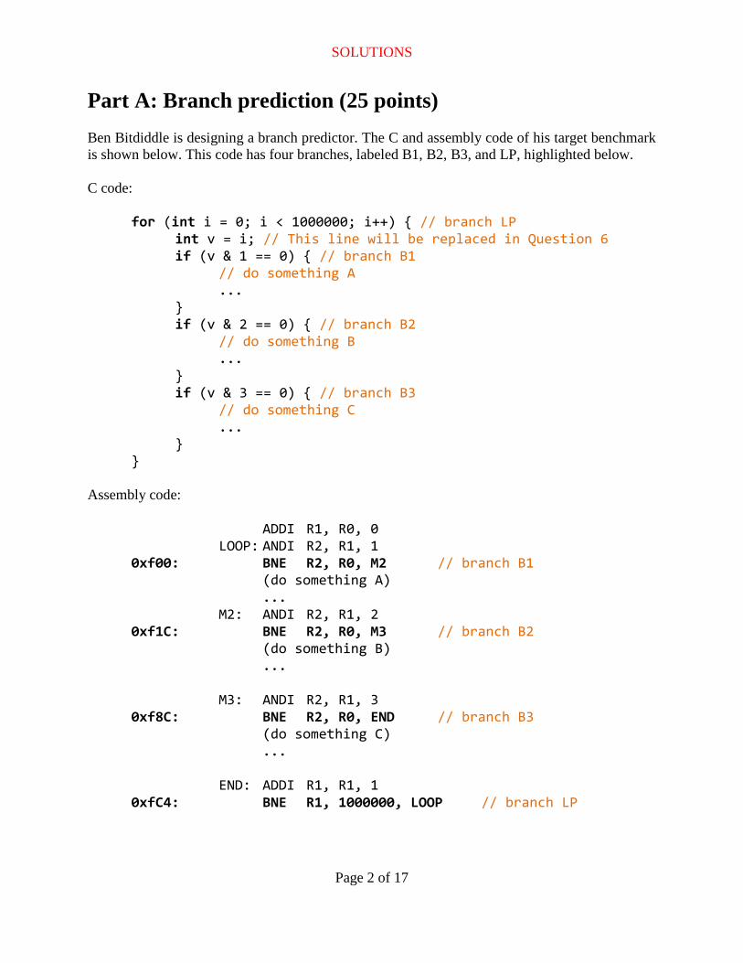
Part A: Branch prediction (25 points)
Ben Bitdiddle is designing a branch predictor. The C and assembly code of his target benchmark
is shown below. This code has four branches, labeled B1, B2, B3, and LP, highlighted below.
C code:
for (int i = 0; i < 1000000; i++) { // branch LP int v = i; // This line will be replaced in Question 6
if (v & 1 == 0) { // branch B1 // do something A ... } if (v & 2 == 0) { // branch B2 // do something B ... } if (v & 3 == 0) { // branch B3 // do something C ...
} }
Assembly code:
ADDI R1, R0, 0 LOOP: ANDI R2, R1, 1 0xf00: BNE R2, R0, M2 // branch B1 (do something A) ... M2: ANDI R2, R1, 2 0xf1C: BNE R2, R0, M3 // branch B2 (do something B) ... M3: ANDI R2, R1, 3 0xf8C: BNE R2, R0, END // branch B3 (do something C) ... END: ADDI R1, R1, 1 0xfC4: BNE R1, 1000000, LOOP // branch LP
SOLUTIONS
Page 3 of 17
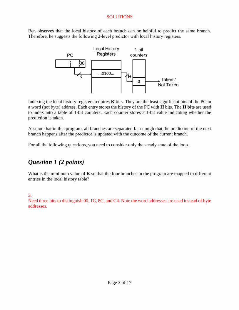
Ben observes that the local history of each branch can be helpful to predict the same branch.
Therefore, he suggests the following 2-level predictor with local history registers.
Indexing the local history registers requires K bits. They are the least significant bits of the PC in
a word (not byte) address. Each entry stores the history of the PC with H bits. The H bits are used
to index into a table of 1-bit counters. Each counter stores a 1-bit value indicating whether the
prediction is taken.
Assume that in this program, all branches are separated far enough that the prediction of the next
branch happens after the predictor is updated with the outcome of the current branch.
For all the following questions, you need to consider only the steady state of the loop.
Question 1 (2 points)
What is the minimum value of K so that the four branches in the program are mapped to different
entries in the local history table?
3.
Need three bits to distinguish 00, 1C, 8C, and C4. Note the word addresses are used instead of byte
addresses.
SOLUTIONS
Page 4 of 17
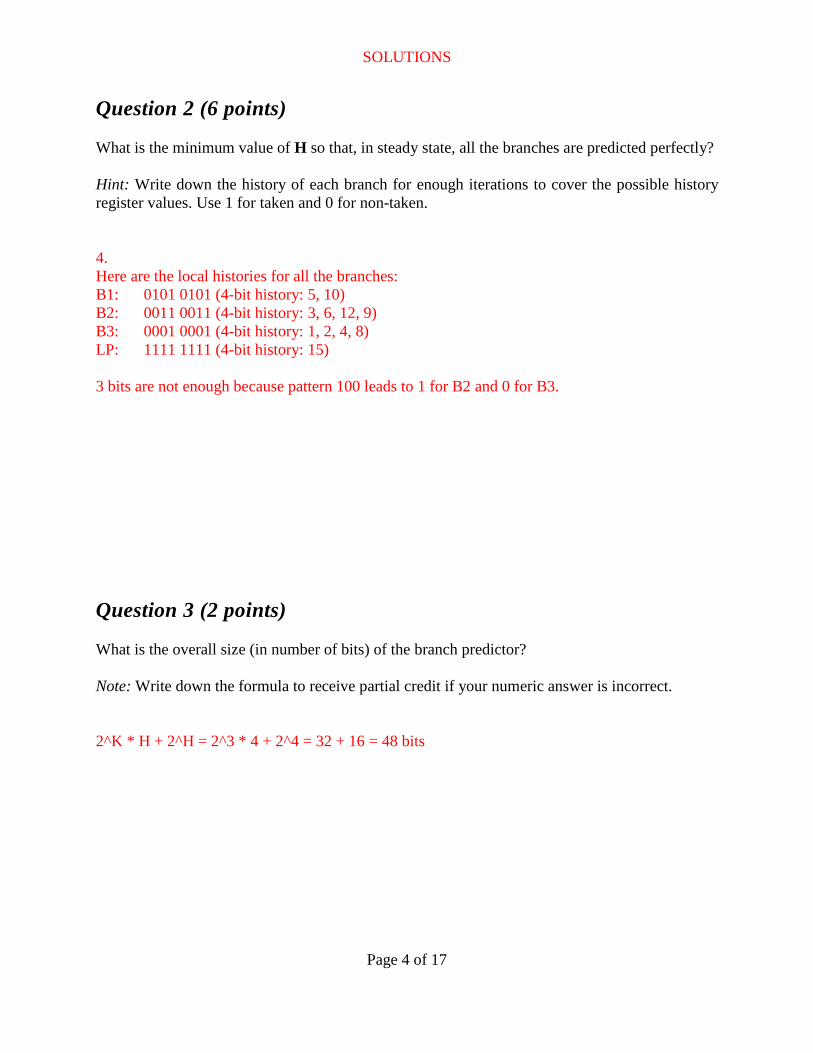
Question 2 (6 points)
What is the minimum value of H so that, in steady state, all the branches are predicted perfectly?
Hint: Write down the history of each branch for enough iterations to cover the possible history
register values. Use 1 for taken and 0 for non-taken.
4.
Here are the local histories for all the branches:
B1: 0101 0101 (4-bit history: 5, 10)
B2: 0011 0011 (4-bit history: 3, 6, 12, 9)
B3: 0001 0001 (4-bit history: 1, 2, 4, 8)
LP: 1111 1111 (4-bit history: 15)
3 bits are not enough because pattern 100 leads to 1 for B2 and 0 for B3.
Question 3 (2 points)
What is the overall size (in number of bits) of the branch predictor?
Note: Write down the formula to receive partial credit if your numeric answer is incorrect.
2^K * H + 2^H = 2^3 * 4 + 2^4 = 32 + 16 = 48 bits
SOLUTIONS
Page 5 of 17
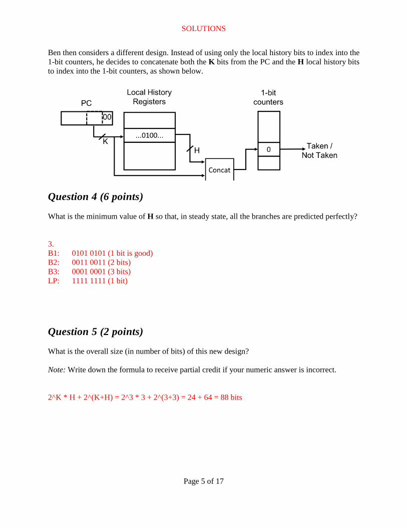
Ben then considers a different design. Instead of using only the local history bits to index into the
1-bit counters, he decides to concatenate both the K bits from the PC and the H local history bits
to index into the 1-bit counters, as shown below.
Question 4 (6 points)
What is the minimum value of H so that, in steady state, all the branches are predicted perfectly?
3.
B1: 0101 0101 (1 bit is good)
B2: 0011 0011 (2 bits)
B3: 0001 0001 (3 bits)
LP: 1111 1111 (1 bit)
Question 5 (2 points)
What is the overall size (in number of bits) of this new design?
Note: Write down the formula to receive partial credit if your numeric answer is incorrect.
2^K * H + 2^(K+H) = 2^3 * 3 + 2^(3+3) = 24 + 64 = 88 bits
SOLUTIONS
Page 6 of 17
Question 6 (2 points)
Ben then looks at a slightly different benchmark. The only difference is that the second line of the
C code is modified from
int v = i;
to int v = a[i];
where a[] is an array of random, uniformly distributed 32-bit integers. In each integer, each bit is
is equally likely to be 0 or 1 and is independent from all other bits.
Will local history predictors work well for branches B1, B2, and B3? Briefly explain why or why
not.
No. Since values are random, successive branch outcomes are not temporally correlated, so local
histories do not bring any benefit (even though B3 is biased and will be taken 75% of the time,
considering its history doesn’t bring any improvement).
Question 7 (5 points)
Still consider the code introduced in Question 6. In steady state, what is the best prediction
accuracy that can be achieved for branches B1, B2, and B3, respectively? State the prediction
mechanism required for each of them.
B1: 50% (unpredictable, so any reasonable prediction mechanism will get 50%)
B2: 50% (unpredictable)
B3: 100% with global history prediction.
SOLUTIONS
Page 7 of 17
Part B: Out-of-order Execution (31 points)
Question 1 (24 points)
This question uses the out-of-order machine described in the Quiz 2 Handout. We describe events
that affect the initial state shown in the handout. Label each event with one of the actions listed in
the handout. If you pick a label with a blank (_____), you also have to fill in the blank using the
choices (i—vii) listed below. If you pick “R. Illegal action”, state why it is an illegal action. If in
doubt, state your assumptions.
Example: I17 finishes and writes P6.
Answer: (G): Write a speculative value using greedy data management.
(You can simply write “G”.)
a) Instruction I13 waits in the issue queue, not executing as long as instruction I11 hasn’t yet
written a result to physical register P7.
(A, i): Satisfy a dependence on a register value by stalling.
b) Assume branch instruction I16 (with target 0x2C) is issued. It is found to be taken.
(K,iii): Check the correctness of a speculation on branch direction and find a correct
speculation
c) Instruction I10 commits, and store buffer entry 2 is marked non-speculative.
(P): Commit correctly speculated instruction, and mark lazily updated values as non-
speculative
d) Assume instruction I16 and I13 are issued, so there are no instructions left in the issue queue
whose operands are ready in the register file, but I13 has not yet written its result to P4. I14 is
issued despite depending on P4 because there is a path for I13 to forward the value while in
flight.
(B, i): Satisfy a dependence on a register value by bypassing a speculative value.
Since we did not specify if I13 has a known latency, we also accepted (B, vi) and (E, vi).
e) Assume I11 finished. I11 commits and the physical register P3 is added to the free list.
(Q): Commit correctly speculated instruction, and free log associated with greedily updated
values. We also gave credit for (R): Illegal action if you assume I10 had not committed.
SOLUTIONS
Page 8 of 17
f) Assume I17 finishes and writes P6, allowing I18 to issue. I18 executes, populating its entry
in the store buffer and marking it valid and speculative.
(F): Write a speculative value using lazy data management
g) Assume P4 becomes available, and I14 executes a store to address 0x8884. It checks the
load buffer, and finds one matching load that is later in program order: I17.
(L, iv): Check the correctness of a speculation on memory address and find an incorrect
speculation.
h) Assume that, as a result of a match in the load buffer, instruction I17 and all later instructions
are flushed after previously being issued. These instructions are reinserted into the issue
queue so they can be reissued.
(N): Abort speculative action and cleanup greedily managed values
i) Assume that after previously being issued, I17 and I18 are flushed. Entry 4 in the store queue
is marked invalid.
(M): Abort speculative action and cleanup lazily managed values
j) Assume instructions up through I16 commit. The snapshot of the rename table associated
with branch I16 is freed.
(Q): Commit correctly speculated instruction, and free log associated with greedily updated
values
k) Assume that, while fetching I21 from 0x3C, the PC 0x3C hits in the BTB, with target 0x74.
The next PC is set to 0x74.
(E, ii): Satisfy a dependence on PC value by speculation using a dynamic prediction
l) Assume that, one cycle after the events in (k) above, I21 from 0x3C is decoded as a conditional
branch, and the branch predictor predicts the branch is not taken. The instruction fetched from
0x74 is squashed (replaced with a pipeline bubble).
(N): Abort speculative action and cleanup greedily managed values
SOLUTIONS
Page 9 of 17
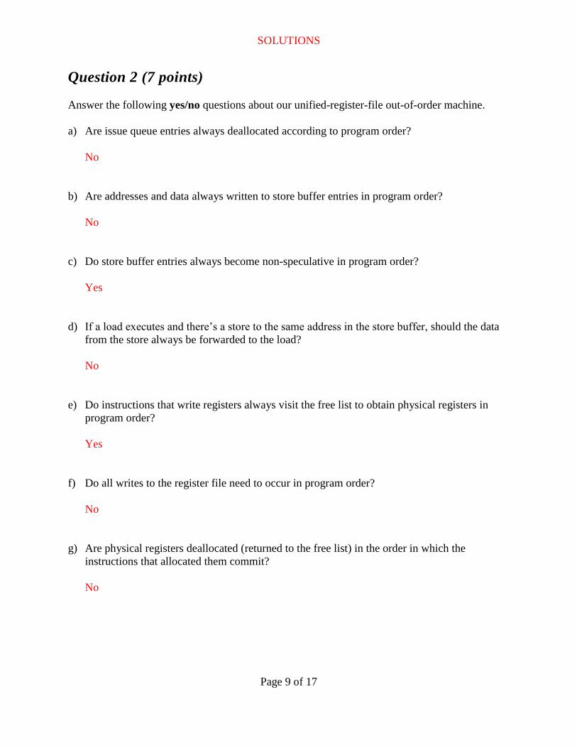
Question 2 (7 points)
Answer the following yes/no questions about our unified-register-file out-of-order machine.
a) Are issue queue entries always deallocated according to program order?
No
b) Are addresses and data always written to store buffer entries in program order?
No
c) Do store buffer entries always become non-speculative in program order?
Yes
d) If a load executes and there’s a store to the same address in the store buffer, should the data
from the store always be forwarded to the load?
No
e) Do instructions that write registers always visit the free list to obtain physical registers in
program order?
Yes
f) Do all writes to the register file need to occur in program order?
No
g) Are physical registers deallocated (returned to the free list) in the order in which the
instructions that allocated them commit?
No
SOLUTIONS
Page 10 of 17
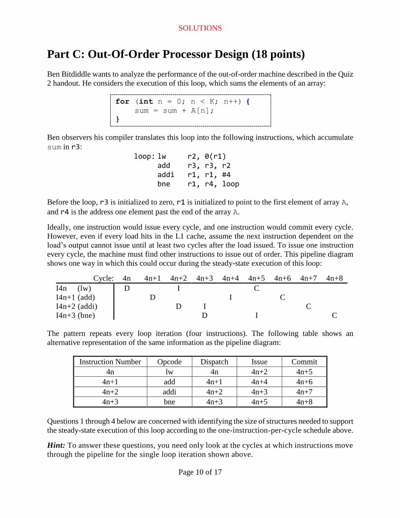
Part C: Out-Of-Order Processor Design (18 points)
Ben Bitdiddle wants to analyze the performance of the out-of-order machine described in the Quiz
2 handout. He considers the execution of this loop, which sums the elements of an array:
Ben observers his compiler translates this loop into the following instructions, which accumulate
sum in r3:
loop: lw r2, 0(r1)
add r3, r3, r2
addi r1, r1, #4
bne r1, r4, loop
Before the loop, r3 is initialized to zero, r1 is initialized to point to the first element of array A,
and r4 is the address one element past the end of the array A.
Ideally, one instruction would issue every cycle, and one instruction would commit every cycle.
However, even if every load hits in the L1 cache, assume the next instruction dependent on the
load’s output cannot issue until at least two cycles after the load issued. To issue one instruction
every cycle, the machine must find other instructions to issue out of order. This pipeline diagram
shows one way in which this could occur during the steady-state execution of this loop:
Cycle: 4n 4n+1 4n+2 4n+3 4n+4 4n+5 4n+6 4n+7 4n+8
I4n (lw) D I C
I4n+1 (add) D I C
I4n+2 (addi) D I C
I4n+3 (bne) D I C
The pattern repeats every loop iteration (four instructions). The following table shows an
alternative representation of the same information as the pipeline diagram:
Instruction Number Opcode Dispatch Issue Commit
4n lw 4n 4n+2 4n+5
4n+1 add 4n+1 4n+4 4n+6
4n+2 addi 4n+2 4n+3 4n+7
4n+3 bne 4n+3 4n+5 4n+8
Questions 1 through 4 below are concerned with identifying the size of structures needed to support
the steady-state execution of this loop according to the one-instruction-per-cycle schedule above.
Hint: To answer these questions, you need only look at the cycles at which instructions move
through the pipeline for the single loop iteration shown above.
for (int n = 0; n < K; n++) { sum = sum + A[n];
}
SOLUTIONS
Page 11 of 17
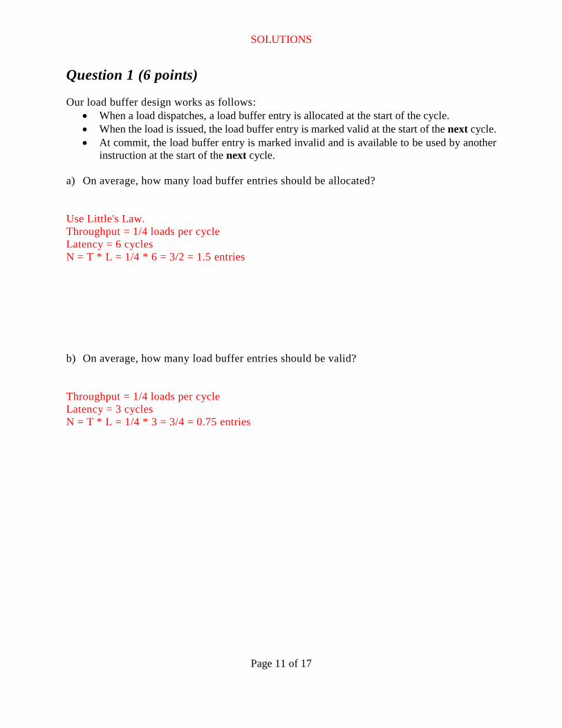
Question 1 (6 points)
Our load buffer design works as follows:
When a load dispatches, a load buffer entry is allocated at the start of the cycle.
When the load is issued, the load buffer entry is marked valid at the start of the next cycle.
At commit, the load buffer entry is marked invalid and is available to be used by another
instruction at the start of the next cycle.
a) On average, how many load buffer entries should be allocated?
Use Little's Law.
Throughput = 1/4 loads per cycle
Latency = 6 cycles
N = T * L = 1/4 * 6 = 3/2 = 1.5 entries
b) On average, how many load buffer entries should be valid?
Throughput = 1/4 loads per cycle
Latency = 3 cycles
N = T * L = 1/4 * 3 = 3/4 = 0.75 entries
SOLUTIONS
Page 12 of 17
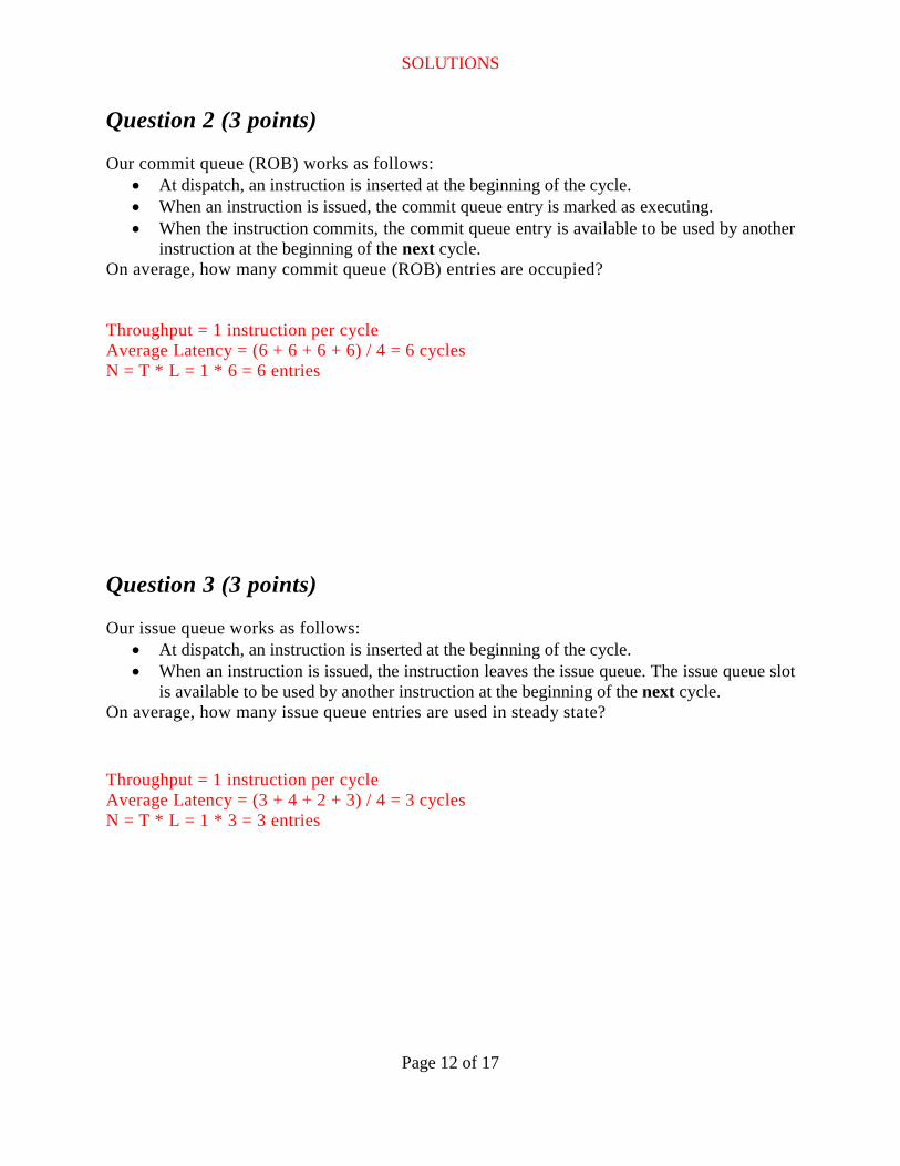
Question 2 (3 points)
Our commit queue (ROB) works as follows:
At dispatch, an instruction is inserted at the beginning of the cycle.
When an instruction is issued, the commit queue entry is marked as executing.
When the instruction commits, the commit queue entry is available to be used by another
instruction at the beginning of the next cycle.
On average, how many commit queue (ROB) entries are occupied?
Throughput = 1 instruction per cycle
Average Latency = (6 + 6 + 6 + 6) / 4 = 6 cycles
N = T * L = 1 * 6 = 6 entries
Question 3 (3 points)
Our issue queue works as follows:
At dispatch, an instruction is inserted at the beginning of the cycle.
When an instruction is issued, the instruction leaves the issue queue. The issue queue slot
is available to be used by another instruction at the beginning of the next cycle.
On average, how many issue queue entries are used in steady state?
Throughput = 1 instruction per cycle
Average Latency = (3 + 4 + 2 + 3) / 4 = 3 cycles
N = T * L = 1 * 3 = 3 entries
SOLUTIONS
Page 13 of 17
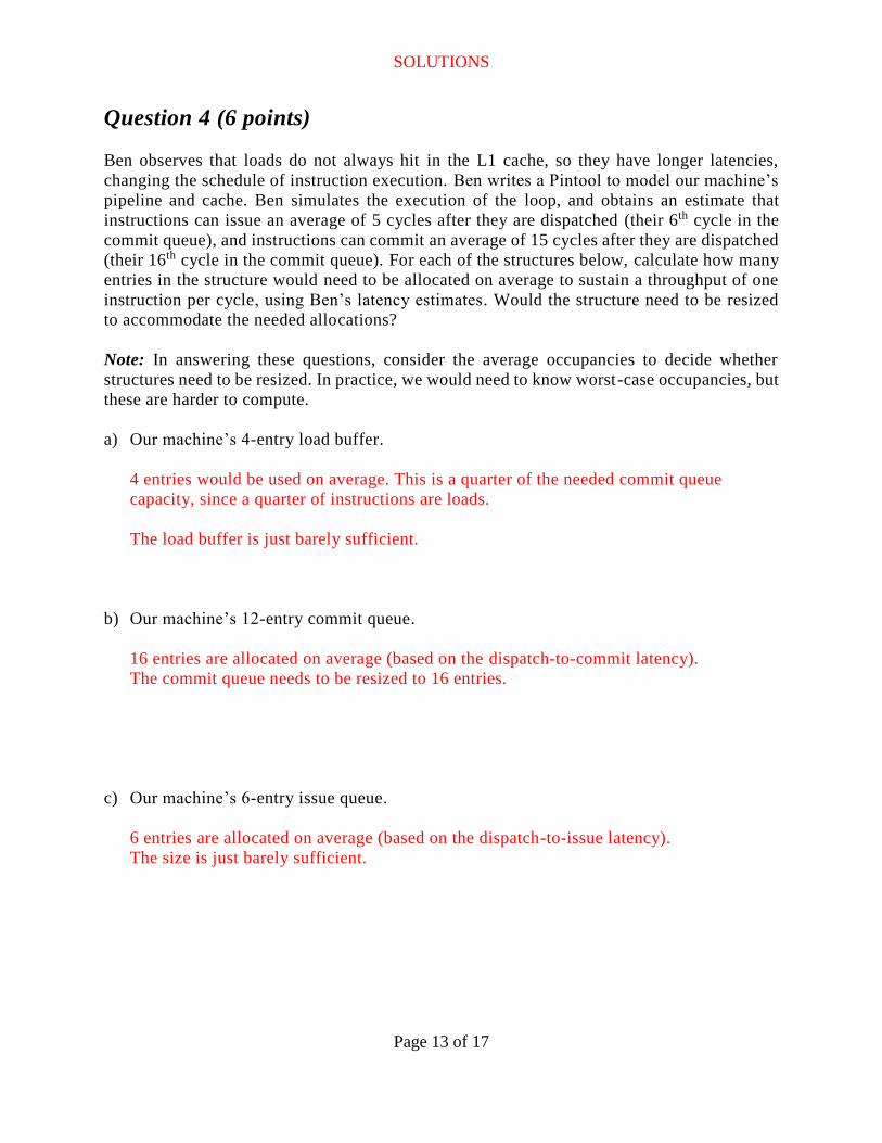
Question 4 (6 points)
Ben observes that loads do not always hit in the L1 cache, so they have longer latencies,
changing the schedule of instruction execution. Ben writes a Pintool to model our machine’s
pipeline and cache. Ben simulates the execution of the loop, and obtains an estimate that
instructions can issue an average of 5 cycles after they are dispatched (their 6th cycle in the
commit queue), and instructions can commit an average of 15 cycles after they are dispatched
(their 16th cycle in the commit queue). For each of the structures below, calculate how many
entries in the structure would need to be allocated on average to sustain a throughput of one
instruction per cycle, using Ben’s latency estimates. Would the structure need to be resized
to accommodate the needed allocations?
Note: In answering these questions, consider the average occupancies to decide whether
structures need to be resized. In practice, we would need to know worst-case occupancies, but
these are harder to compute.
a) Our machine’s 4-entry load buffer.
4 entries would be used on average. This is a quarter of the needed commit queue
capacity, since a quarter of instructions are loads.
The load buffer is just barely sufficient.
b) Our machine’s 12-entry commit queue.
16 entries are allocated on average (based on the dispatch-to-commit latency).
The commit queue needs to be resized to 16 entries.
c) Our machine’s 6-entry issue queue.
6 entries are allocated on average (based on the dispatch-to-issue latency).
The size is just barely sufficient.
SOLUTIONS
Page 14 of 17
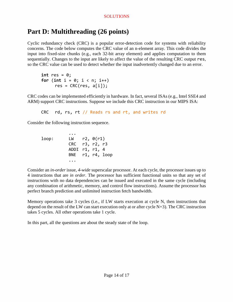
Part D: Multithreading (26 points)
Cyclic redundancy check (CRC) is a popular error-detection code for systems with reliability
concerns. The code below computes the CRC value of an n-element array. This code divides the
input into fixed-size chunks (e.g., each 32-bit array element) and applies computation to them
sequentially. Changes to the input are likely to affect the value of the resulting CRC output res,
so the CRC value can be used to detect whether the input inadvertently changed due to an error.
int res = 0; for (int i = 0; i < n; i++) res = CRC(res, a[i]);
CRC codes can be implemented efficiently in hardware. In fact, several ISAs (e.g., Intel SSE4 and
ARM) support CRC instructions. Suppose we include this CRC instruction in our MIPS ISA:
CRC rd, rs, rt // Reads rs and rt, and writes rd
Consider the following instruction sequence.
... loop: LW r2, 0(r1) CRC r3, r2, r3
ADDI r1, r1, 4 BNE r1, r4, loop ...
Consider an in-order issue, 4-wide superscalar processor. At each cycle, the processor issues up to
4 instructions that are in order. The processor has sufficient functional units so that any set of
instructions with no data dependencies can be issued and executed in the same cycle (including
any combination of arithmetic, memory, and control flow instructions). Assume the processor has
perfect branch prediction and unlimited instruction fetch bandwidth.
Memory operations take 3 cycles (i.e., if LW starts execution at cycle N, then instructions that
depend on the result of the LW can start execution only at or after cycle N+3). The CRC instruction
takes 5 cycles. All other operations take 1 cycle.
In this part, all the questions are about the steady state of the loop.

SOLUTIONS
Page 15 of 17
Question 1 (6 points)
Suppose the machine runs the program shown on the previous page.
Show the steady-state schedule of this processor. To do this, consider two consecutive loop
iterations, and list which instructions are issued on each cycle (i.e., write the instructions issued
in cycle 0, then in cycle 1, etc., until you cover two iterations).
In the steady state, what is the IPC (instructions per cycle) of the processor?
Hint: The schedule of the first iteration may not be in the steady state. You might need to
experiment with more iterations.
This is dictated by the CRC latency. Here is what issues look like:
Cycle 0: CRC, ADDI // source r3 will be ready in cycle 5
Cycle 1: BNE, LW // source r2 will be ready in cycle 4
Cycle 2: -
Cycle 3: -
Cycle 4: -
Cycle 5: CRC, ADDI
Cycle 6: BNE, LW
IPC = 4 instructions / 5 cycles = 0.8 instructions/cycle
Question 2 (3 points)
Would out-of-order issue improve the performance of the code on this machine?
No. The critical path is dictated by CRC latency.
SOLUTIONS
Page 16 of 17
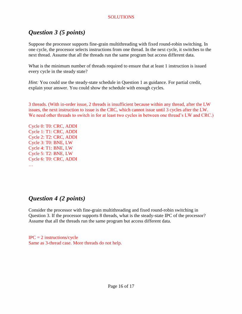
Question 3 (5 points)
Suppose the processor supports fine-grain multithreading with fixed round-robin switching. In
one cycle, the processor selects instructions from one thread. In the next cycle, it switches to the
next thread. Assume that all the threads run the same program but access different data.
What is the minimum number of threads required to ensure that at least 1 instruction is issued
every cycle in the steady state?
Hint: You could use the steady-state schedule in Question 1 as guidance. For partial credit,
explain your answer. You could show the schedule with enough cycles.
3 threads. (With in-order issue, 2 threads is insufficient because within any thread, after the LW
issues, the next instruction to issue is the CRC, which cannot issue until 3 cycles after the LW.
We need other threads to switch in for at least two cycles in between one thread’s LW and CRC.)
Cycle 0: T0: CRC, ADDI
Cycle 1: T1: CRC, ADDI
Cycle 2: T2: CRC, ADDI
Cycle 3: T0: BNE, LW
Cycle 4: T1: BNE, LW
Cycle 5: T2: BNE, LW
Cycle 6: T0: CRC, ADDI
…
Question 4 (2 points)
Consider the processor with fine-grain multithreading and fixed round-robin switching in
Question 3. If the processor supports 8 threads, what is the steady-state IPC of the processor?
Assume that all the threads run the same program but access different data.
IPC = 2 instructions/cycle
Same as 3-thread case. More threads do not help.
SOLUTIONS
Page 17 of 17
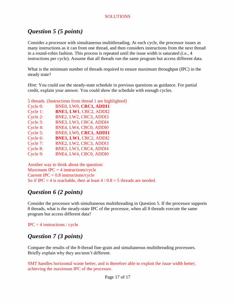
Question 5 (5 points)
Consider a processor with simultaneous multithreading. At each cycle, the processor issues as
many instructions as it can from one thread, and then considers instructions from the next thread
in a round-robin fashion. This process is repeated until the issue width is saturated (i.e., 4
instructions per cycle). Assume that all threads run the same program but access different data.
What is the minimum number of threads required to ensure maximum throughput (IPC) in the
steady state?
Hint: You could use the steady-state schedule in previous questions as guidance. For partial
credit, explain your answer. You could show the schedule with enough cycles.
5 threads. (Instructions from thread 1 are highlighted)
Cycle 0: BNE0, LW0, CRC1, ADDI1
Cycle 1: BNE1, LW1, CRC2, ADDI2
Cycle 2: BNE2, LW2, CRC3, ADDI3
Cycle 3: BNE3, LW3, CRC4, ADDI4
Cycle 4: BNE4, LW4, CRC0, ADDI0
Cycle 5: BNE0, LW0, CRC1, ADDI1
Cycle 6: BNE1, LW1, CRC2, ADDI2
Cycle 7: BNE2, LW2, CRC3, ADDI3
Cycle 8: BNE3, LW3, CRC4, ADDI4
Cycle 9: BNE4, LW4, CRC0, ADDI0
Another way to think about the question:
Maximum IPC = 4 instructions/cycle
Current IPC = 0.8 instructions/cycle
So if IPC = 4 is reachable, then at least 4 / 0.8 = 5 threads are needed.
Question 6 (2 points)
Consider the processor with simultaneous multithreading in Question 5. If the processor supports
8 threads, what is the steady-state IPC of the processor, when all 8 threads execute the same
program but access different data?
IPC = 4 instructions / cycle
Question 7 (3 points)
Compare the results of the 8-thread fine-grain and simultaneous multithreading processors.
Briefly explain why they are/aren’t different.
SMT handles horizontal waste better, and is therefore able to exploit the issue width better,
achieving the maximum IPC of the processor.