Embed Size (px)
Citation preview

Computer Systems Organization
Chapter 2
Some slides © 2006 Pearson Education Inc, all rights reserved

Central Processing Unit
The organization of a simple computer with one CPU and two I/O devices

CPU OrganizationThe data path of a typical Von Neumann
machine.

Instruction Execution Steps• Fetch next instruction from memory into instr.
register• Change program counter to point to next
instruction• Determine type of instruction just fetched• If instructions uses word in memory, determine
where Fetch word, if needed, into CPU register• Execute the instruction• Go to step 1 to begin executing following
instruction

Interpreter (1)
An interpreter for a simple computer (written in Java).
. . .

Interpreter (2)
An interpreter for a simple computer (written in Java).

Design Principles for Modern Computers
• All instructions directly executed by hardware
• Maximize rate at which instructions are issued
• Instructions should be easy to decode
• Only loads, stores should reference memory
• Provide plenty of registers

Instruction-Level Parallelism
• A five-stage pipeline• The state of each stage as a function of time. Nine
clock cycles are illustrated

Superscalar Architectures (1)
Dual five-stage pipelines with a common instruction fetch unit.

Superscalar Architectures (2)
A superscalar processor with five functional units.

Processor-Level Parallelism (1)
An array of processor of the ILLIAC IV type.

Processor-Level Parallelism (2)
• A single-bus multiprocessor.
• A multicomputer with local memories.

Primary MemoryMemory Addresses (1)
Three ways of organizing a 96-bit memory.

Primary MemoryMemory Addresses (2)
Number of bits per cell for some historically interesting commercial computers

Byte Ordering (1)
(a) Big endian memory (b) Little endian memory

Byte Ordering (2)
(a) A personal record for a big endian machine.
(b) The same record for a little endian machine.
(c) The result of transferring from big endian to little endian.
(d) The result of byte-swapping (c).

Error Checking vs Error Correcting
• For memory:
• PC - no checking
• Parity – finds one bit errors
• ECC
• Corrects 1 bit errors
• Finds 2 bit errors

Parity
• May be odd or even – arbitrary (hardware) decision
• Detects single bit errors• Does not correct• Calculated on store • Checked on Load• Minimal added storage requirement• Implemented in hardware

Parity Example
• Pick even parity
• Store a 3 in memory 0011
• With even parity 00110 is stored
• Load a 3 from memory get 00110 if correct
• Errors could include– 00111– 00101– 00010
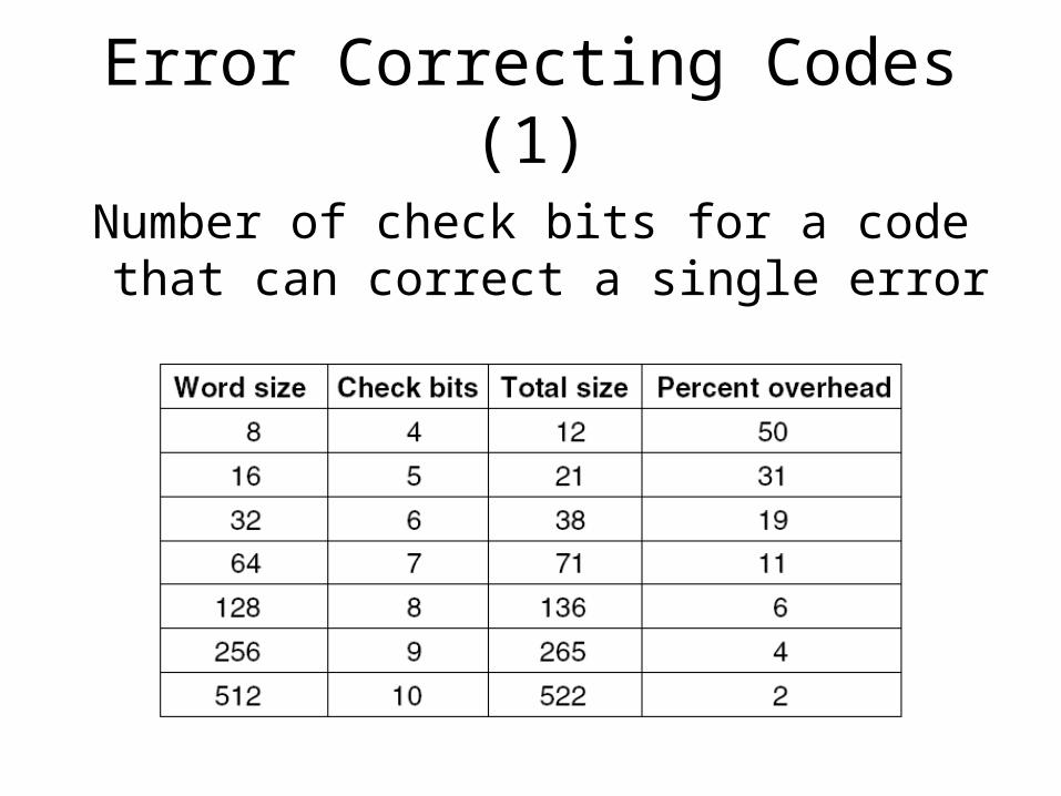
Error Correcting Codes (1)
Number of check bits for a code that can correct a single error

Error-Correcting Codes
– Occasional errors may occur in computer memories due to voltage spikes or other causes.
– Errors can be handles by adding extra check bits to words of memory. Suppose a word of memory has m data bits and r check bits. Let the total length be n = m + r. This n bit unit is often referred to as a codeword.
– The number of bits in which two codewords differ is called the Hamming distance.

Error-Correcting Codes
– Imagine we want to design a code with m data bits and r check bits that will allow all single-bit errors to be corrected. Each of the 2m legal memory words has n illegal codewords at a distance 1 from it.
• Form these by inverting each of the n bits in the n-bit codeword.
• Each of the 2m legal memory words requires n + 1 bit patterns dedicated to it.
• (n + 1) 2m <= 2r since n = m + r, (m + r + 1) <= 2r

Error-Correcting Codes
• The following figure illustrates an error-correcting code for 4-bit words. The three circles form 7 regions. Encode the 4-bit word 1100 in four of those regions then add a parity bit to each of the three empty regions so that the sum of the bits in each circle is an even number.
• Now suppose that the bit in the AC region goes bad, changing from a 0 to a 1. Circles A and C have the wrong parity. The only single-bit change that corrects them is to restore AC back to 0, thus correcting the error.

Error Correcting Codes (2)
(a) Encoding of 1100
(b) Even parity added
(c) Error in AC

Hamming’s Algorithm
– Hamming’s algorithm can be used to construct single error-correcting codes for any size memory word. In a Hamming code, r parity bits are added to an m-bit word, forming a new word of length m + r bits.
– The bits are numbered starting at 1, not 0, with bit 1 the leftmost (high-order) bit. All bits whose bit number is a power of 2 are parity bits; the rest are used for data.
• In a 16-bit word, 5 parity bits are added. Bits 1, 2, 4, 8, and 16 are parity bits. The word has 21 total bits.

Hamming’s Algorithm
– Each parity bit checks specific bit positions; the parity bit is set so that the total number of 1s in the checked positions is even. The positions checked are:
Bit 1 checks bits 1, 3, 5, 7, 9, 11, 13, 15, 17, 19, 21.
Bit 2 checks bits 2, 3, 6, 7, 10, 11, 14, 15, 18, 19.
Bit 4 checks bits 4, 5, 6, 7, 12, 13, 14, 15, 20, 21.
Bit 8 checks bits 8, 9, 10, 11, 12, 13, 14, 15.
Bit 16 checks bits 16, 17, 18, 19, 20, 21.
• In general each bit b is checked by those bits b1, b2, …, bj such that b1 + b2 + … + bj = b.

Hamming’s Algorithm
– Consider what would happen if bit 5 in the word on the previous slide were inverted by a surge on the power line. Bit 5 would then be a 1. The 5 parity bits would be checked with the following results:
Parity bit 1 incorrect (positions checked contain 5 1s)
Parity bit 2 correct (positions checked contain 6 1s)
Parity bit 4 incorrect (positions checked contain 5 1s)
Parity bit 8 correct (positions checked contain two 1s)
Parity bit 16 correct (positions checked contain four 1s)

Hamming’s Algorithm
– The incorrect bit must be one of the bits checked by parity bit 1 and by parity bit 4. These are bits 5, 7, 13, 15, or 21. However, bit 2 is correct, eliminating 7 and 15. Similarly, bit 8 is correct, eliminating 13. Finally, bit 16 is correct, eliminating 21. The only bit left is 5, which is the one in error.
– If all parity bits are correct, there were no errors (or more than one). Otherwise, add up all the incorrect parity bits. The sum gives the position of the incorrect bit.

Error Correcting Codes (3)
Construction of the Hamming code for the memory word 11110000010101110 by adding 5 check bits to the 16 data bits.

Cache Memory
The cache is logically between the CPU and main memory. Physically, there are several possible places it could be located.

Memory Packaging and Types
A single inline memory module (SIMM) holding 256 MB. Two of the chips control the SIMM.

Memory Hierarchies
A five-level memory hierarchy.
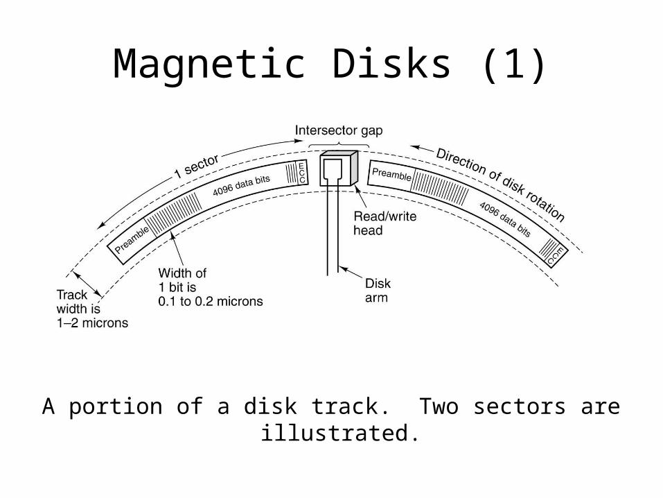
Magnetic Disks (1)
A portion of a disk track. Two sectors are illustrated.

Magnetic Disks (2)
A disk with four platters.
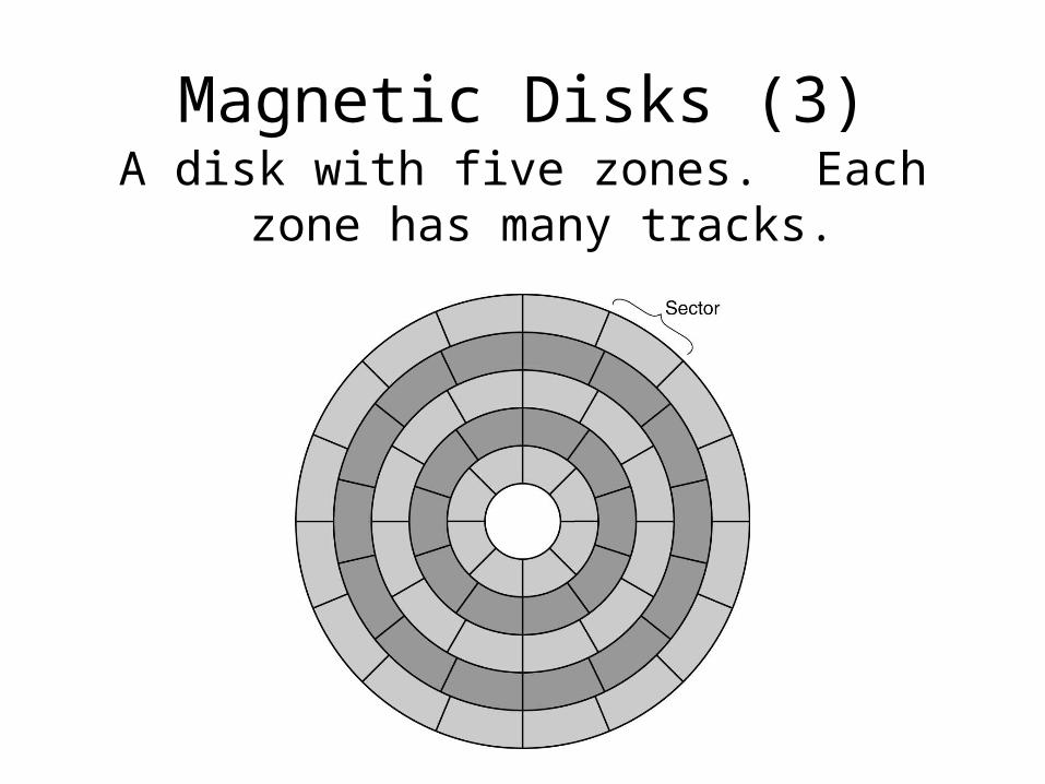
Magnetic Disks (3)A disk with five zones. Each zone has many
tracks.

SCSI DisksSome of the possible SCSI parameters.

RAID (1) Redundant Array of Inexpensive Disks
RAID levels 0 through 2. Backup and parity disks are shown shaded.

RAID (1) Redundant Array of Inexpensive Disks
RAID levels 3 through 5. Backup and parity disks are shown shaded.

CD-ROMs (1)
Recording structure of a Compact Disk or CD-ROM.

CD-ROMs (2)
Logical data layout on a CD-ROM.

CD-Recordables
Cross section of a CD-R disk and laser (not to scale). A CD-ROM has a similar structure, except without the dye layer and with a pitted aluminum layer instead of a reflective layer.

DVD
A double-sided, dual layer DVD disk.

Input/OutputBuses (1)
Physical structure of a personal computer.

Input/OutputBuses (2)
Logical structure of a simple personal computer.

Input/OutputBuses (3)
A typical modern PC with a PCI bus and an ISA bus.

CRT Monitors
(a) Cross section of a CRT
(b) CRT scanning pattern

Flat Panel Displays
(a) The construction of an LCD screen.
(b) The grooves on the rear and front plates are perpendicular to one another.

Mice
A mouse being used to point to menu items.

Printers (1)
(a) The letter “A” on a 5 x 7 matrix. (b) The letter “A” printed with 24 overlapping needles.

Printers (2)
Operation of a laser printer.

Printers (3)
Halftone dots for various gray scale ranges.
(a) 0 – 6. (b) 14 – 20. (c) 28 – 34.
(d) 56 – 62. (e) 105 – 111. (f) 161 – 167.

Telecommunications
• Transmission of the binary number 01001010000100 over a • telephone line bit by bit. (a) Two-level signal. (b) Amplitude • modulation. (c) Frequency modulation. (d) Phase modulation.

Digital Subscriber Lines (1)
Operation of ADSL.
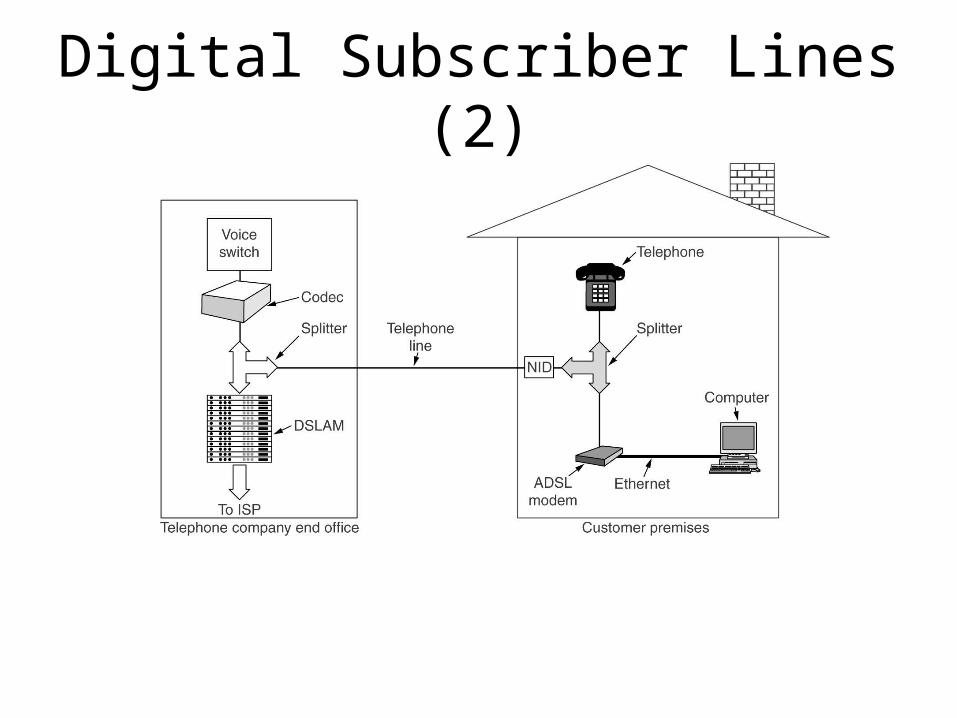
Digital Subscriber Lines (2)
A typical ADSL equipment configuration.

Internet over Cable (1)
Frequency allocation in a typical cable TV system used for Internet access

Internet over Cable (2)
Typical details of the upstream and downstream channels in North America. QAM-64 (Quadrature
Amplitude Modulation) allows 6 bits/Hz but only works at high frequencies. QPSK (Quadrature Phase Shift
Keying) works at low frequencies but allows only 2 bits/Hz.

Digital Cameras
A digital camera.

ASCII Character Codes (1)
The ASCII Character set: characters 0 – 31.

ASCII Character Codes (2)
The ASCII Character set: characters 32 – 127.