Embed Size (px)
Citation preview
COMPUTERIZED INVENTORY OF DATA
ON TEXAS SALT DOMES
Steven J. Seni, W. F. Mullican III, and R. W. Ozment
Contract Report for the Texas Department of Water Resources under Contract No. lAC (84-85)-1019
Bureau of Economic Geology W. L. Fisher, Director
The University of Texas at Austin University Station, P.O. Box X
Austin, Texas 78713-7508
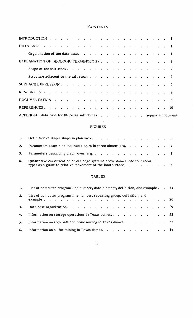
CONTENTS
INTRODUCTION • 1
DATA BASE 1
Organization of the data base. 1
EXPLANA TION OF GEOLOGIC TERMINOLOGY. 2
Shape of the salt stock. 2
Structure adjacent to the salt stock • 5
SURF ACE EXPRESSION. 5
RESOURCES • 8
DOCUMENT A TION 8
REFERENCES. 10
APPENDIX: data base for 84 Texas salt domes separate document
1.
2.
3.
4.
1.
2.
3.
4.
5.
6.
FIGURES
Definition of diapir shape in plan view ••
Parameters describing inclined diapirs in three dimensions. •
Parameters describing diapir overhang. •
Qualitative classification of drainage systems above domes into four ideal types as a guide to relative movement of the land surface
TABLES
List of computer program line number, data element, definition, and example.
List of computer program line number, repeating group, definition, and example.
Data base organization.
Information on storage operations in Texas domes ••
Information on rock salt and brine mining in Texas domes.
Information on sulfur mining in Texas domes. •
ii
3
4
6
7
14
20
29
32
33
34
INTRODUCTION
On the basis of our initial investigations, a computerized spread sheet has been derived
that summarizes information relevant to storing chemical wastes in salt domes in Texas. This
inventory provides a ready reference source of dome-related data including location, physical
dimensions and structure of the domes, surrounding strata, domal resources, and ground water.
The data base is especially useful for manipulating data and creating lists and tables to compare
individual domes and their potential uses and resources.
DATA BASE
The inventory is stored on System 2000 (S2K). S2K provides the user with a powerful tool
for managing the data base. With S2K the user may define new data bases, modify definitions
in existing data bases, and retrieve and update values within the data bases. S2K provides
archival copies of data bases and records an audit trail to changes in the data base.
The structure of the data base is hierarchical. Basic components of the data base are
data elements and repeating groups. Values (either numeric or text) are stored in data
elements. Repeating groups are the structure for storing related sets of data elements.
Repeating groups link hierarchical levels of the data base. Output in the form of tables and
reports is generated with the "Report Writer."
Organization of the Data Base
Single data elements include 55 dome variables listed and defined in table 1. Repeating
groups include 16 sets of data elements comprising 63 individual data elements listed and
defined in table 2. The organization of the data base is shown in table 3; the entire data base as
of May 1, 1984, constitutes appendix 1. The "Report Writer" feature of S2K facilitates
preparation of charts and tables of data from the data base. Tables 4, 5, and 6 are examples of
1
output using the "Report Writer." The code needed to reproduce these tables is included at the
bottom of the individual tables.
EXPLANA TION OF GEOLOGIC TERMINOLOGY
Information on 84 salt diapirs in Texas is presented in the data base. Some salt pillows
(nondiapiric salt structures) may also be included. Data for very deep salt structures is meager.
The availability of data for each dome is variable. Structure-contour maps on top of domal
material are available for 52 domes (62 percent of the total).
All data elements and repeating groups are listed by program line (pl) and defined in
tables 1 and 2. Most geologic terms are self explanatory. The following sections and
figures 1, 2, 3, and 4 provide an explanation of the geologic terminology. In the following
sections parameters in the data base are keyed to a program line in parentheses. All
documentation of the source of data is listed in Documentation Repeating Group (pl-500).
Shape of the Salt Stock
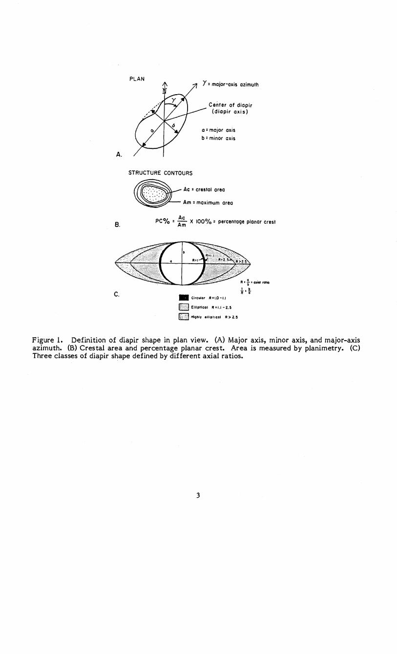
Several parameters describe the shape of the salt stock. Shape parameters are derived
from structure-contour maps on top of the stock. Figure lA illustrates how major-axis length
(pl-31), major-axis orientation (pl-32), and minor-axis length (pl-33) were derived. Area of
planar crest (pl-40) and planar crest percentage (pl-41) were calculated as shown in figure lB.
Axial ratio is a measure of the ellipticity of a diapir (fig. lC).
The area (ft2) enclosed by each domal-structure contour was calculated by planimetry and
is in Area Statistics Repeating Group (pl-34).
Salt-structure contour maps also yield data on the three-dimensional shape of the salt
stock. Diapirs not having vertical axes are described in terms of axial tilt (pI-55), axial-tilt
orientation (pI-56), and axial-tilt distance (pI-57) in figure 2. The presence and position of the
salt-stock overhang determine whether the sides of the stock (pI-59) are parallel (no overhang),
2
A.
8.
c.
PLAN r: major-axis azimuth
C enter of diapir (diapir axis)
a: major axis
b : minor axis
STRUCTURE CONTOURS
~ Ac : crestal area
~ Am: maximum area
Ac PColo : Am X 100°/0: percentage planar crest
• Circular R >1.0 -1.1
IC2l ElliptiCal R>I.I-2.5
k:'d Hlqftly .lIip',cal R> 2.5
Rat: Gltal ratio
I b R'a'i
Figure 1. Definition of diapir shape in plan view. (A) Major axis, minor axis, and major-axis azimuth. (8) Crestal area and percentage planar crest. Area is measured by planimetry. (C) Three classes of diapir shape defined by different axial ratios.
3
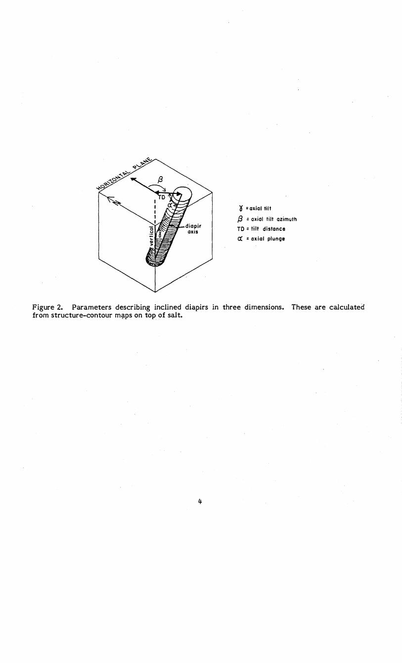
(f = axial tilt
/3 = axial tilt azimuth
TO = tilt distance
ex = axial plunge
Figure 2. Parameters describing inclined diapirs in three dimensions. These are calculated from structure-contour m~ps on top of salt.
4
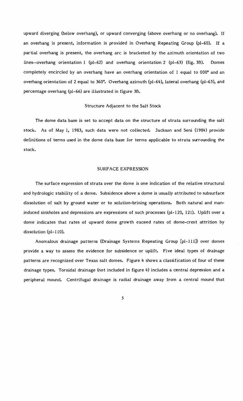
upward diverging (below overhang), or upward converging (above overhang or no overhang). If
an overhang is present, information is provided in Overhang Repeating Group (pl-60). If a
partial overhang is present, the overhang arc is bracketed by the azimuth orientation of two
lines--overhang orientation 1 (pl-62) and overhang orientation 2 (pl-63) (fig. 3B). Domes
completely encircled by an overhang have an overhang orientation of 1 equal to 000° and an
overhang orientation of 2 equal to 360°. Overhang azimuth (pl-64), lateral overhang (pl-65), and
percentage overhang (pl-66) are illustrated in figure 3B.
Structure Adjacent to the Salt Stock
The dome data base is set to accept data on the structure of strata surrounding the salt
stock. As of May 1, 1983, such data were not collected. Jackson and Seni (1984) provide
definitions of terms used in the dome data base for terms applicable to strata surrounding the
stock.
SURF ACE EXPRESSION
The surface expression of strata over the dome is one indication of the relative structural
and hydrologic stability of a dome. Subsidence above a dome is usually attributed to subsurface
dissolution of salt by ground water or to solution-brining operations. Both natural and man
induced sinkholes and depressions are expressions of such processes (pl-I20, 121). Uplift over a
dome indicates that rates of upward dome growth exceed rates of dome-crest attrition by
dissolution (pl-llO).
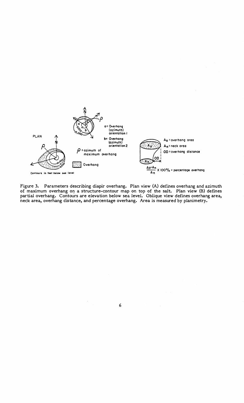
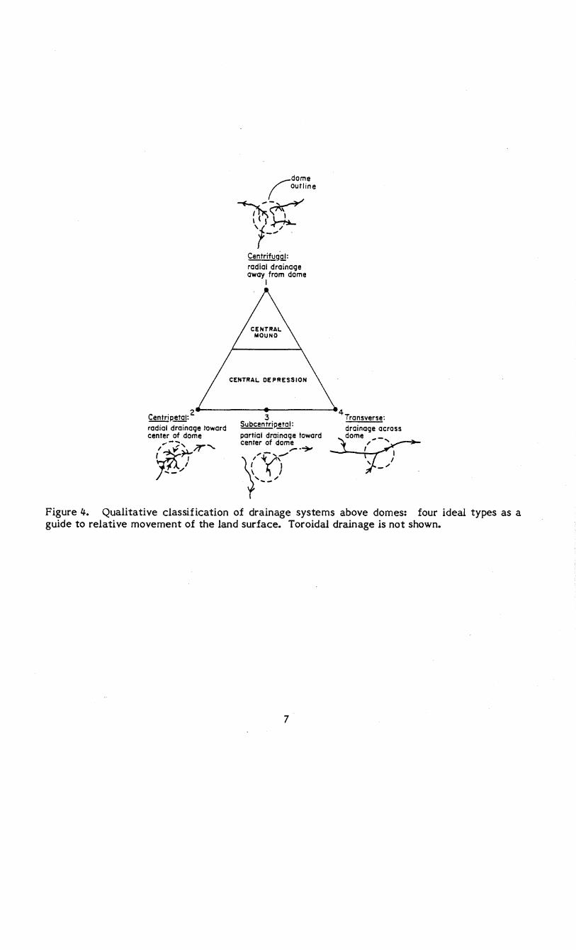
Anomalous drainage patterns (Drainage Systems Repeating Group [pI-Ill]) over domes
provide a way to assess the evidence for subsidence or uplift. Five ideal types of drainage
patterns are recognized over Texas salt domes. Figure 4 shows a classification of four of these
drainage types. Toroidal drainage (not included in figure 4) includes a central depression and a
peripheral mound. Centrifugal drainage is radial drainage away from a central mound that
5
a= Overhang (azimuth) arientation I
b= Overhang (azimuth) orientation 2
P = azimuth of maximum overhang
Ir::.A Overhang
Contours In fHt o.low sea level
Ao : overhang area
An = neck area
00 = overhang distance
Ao-An ~ X 100% = percentage overhang
Figure 3. Parameters describing diapir overhang. Plan view (A) defines overhang and azimuth of maximum overhang oJ? a structure-contour map on top of the salt. Plan view (B) defines partial overhang. Contours are elevation below sea level. Oblique view defines overhang area, neck area, overhang distance, and percentage overhang. Area is measured by planimetry.
6
Centrifug2!: radiat drainage away from dome
I
CENTRAL DEPRESSION
2e-----------~-----------44 C_e_n_t_rip'_et_al: 3 Transverse: radial drainage toward Subcentrip'etal: center of dome partial drainage toward
-... center of dome
~;r" \(YJr ... p~. y>-'
Figure 4. Qualitative classification of drainage systems above domes: four ideal types as a guide to relative movement of the land surface. Toroidal drainage is not shown.
7
occurs over domes rising faster than the overburden is being eroded or the crest is being
dissolved. Centripetal drainage is drainage toward the central area over the salt stock. It
provides evidence of collapse over the dome crest. Subcentripetal drainage suggests subsidence
but is equivocal evidence. Transverse drainage indicates that any rise or subsidence of the
dome is negligible compared with the rate of regional uplift or subsidence and stream incision
or aggradation.
RESOURCES
Hydrocarbon production histories from producing salt domes are listed in Hydrocarbon
Repeating Group (pl-150). These data are from the 1982 Railroad Commission Oil and Gas
Annual Report. Other resources associated with diapirs include rock salt, brine, sulfur, and
sulfide minerals. These resources and history of development are listed in Mineral Production
Repeating Group (pl-190). Solution-mined storage caverns represent another domal resource.
Data domes with a history of hydrocarbon storage, company, number of caverns, capacities, and
products stored are listed in Hydrocarbon Storage Caverns Repeating Group (pl-225).
Ground-water resources around domes are listed in Aquifer Water Chemistry Repeating
Group (pl-400). Water chemistry data are from Texas Department of Water Resources water
chemistry wells. In addition to water chemistry, the following ground-water parameters are
listed; regional depth of slightly saline ground water (pl-420), depth of slightly saline ground
water near the dome (pl-421), ground-water irrigation near the dome (pl-435), municipalities
using ground water near the dome (Repeating Group pl-425), and industries using ground water
near the dome (Repeating Group pl-430).
DOCUMENT A TION
Each dome includes a Documentation Repeating Group indicating the source of data. The
information on each dome can be divided into three major classes of related data--dome
8

geometry, dome resources, and ground-water chemistry. Most of the data in these classes were
derived from outside sources. All other data were generated at the Bureau of Economic
Geology for this report.
Data on dome location and geometry were derived from salt-structure contour maps.
Major sources of these contour maps are the Railroad Commission of Texas Hearing Files,
Jackson and Seni (1984), Halbouty (1979), Geomap, and numerous articles on individual domes.
Resource data include oil and gas, sulfur, sulfides, salt, brine, and storage. All oil and gas data
are from the Railroad Commission of Texas 1982 Oil and Gas Annual Report. Most data on
sulfur, salt, and brine are from Hawkins and Jirik (1966) and Jirik and Weaver (1976). Data on
sulfide minerals are from Smith (1970a, b) and Price and others (1983). Data on storage in salt
domes are from the Railroad Commission of Texas Hearing Files and Gas Processors
Association (1983). The Texas Department of Water Resources provided data on ground-water
chemistry and uses of ground water.
9
REFERENCES
Barton, D. C., 1920, The Palangano salt dome, Duval County, Texas: Economic Geology, v. 6,
p.497-510.
Behrman, R. G., Jr., 1953, Thompson Field, Fort Bend County, Texas: in McNaughton, D. A.,
ed., Typical oil and gas fields of southeast Texas: Houston Geological Society, Guidebook,
Joint Annual Meeting, 1953, Houston, Texas, American Association of Petroleum Geolo
gists, Society of Economic Paleontologists and Mineralogists, and Society of Exploration
Geophysicists, p. 156-160.
Burford, S. 0., 1935, Structural features of Brenham salt dome, Washington and Austin
Counties, Texas: American Association of Petroleum Geologists Bulletin, v.9, no. 9,
p.1330-1338.
Canada, W. R., 1953, Hockley Oil Field, Harris County, Texas: in McNaughton, D. A., ed.,
Typical oil and gas fields of southeast Texas: Houston Geological Society, Guidebook,
Joint Annual Meeting, 1953, Houston, Texas, American Association of Petroleum Geol
ogists, Society of Economic Paleontologists and Mineralogists, and Society of Exploration
Geophysicists, p. 76-79.
Davies, W. J., 1953, BrookShire (San Felipe) Field, Waller County, Texas: in McNaughton, D. A.,
ed., Typical oil and gas fields of southeast Texas: Houston Geological Society, Guidebook,
Joint Annual Meeting, 1953, Houston, Texas, American Association of Petroleum Geolo
gists, Society of Economic Paleontologists and Mineralogists, and Society of Exploration
Geophysicists, p. 97-99.
Ferguson, W. B., and Minton, J. W., 1936, Clay Creek salt dome, WaShington County, Texas:
American Association of Petroleum Geologists Bulletin, v. 20, no. 1, p. 68-90.
Gas Processors Association, 1983, North American storage capacity for light hydrocarbons and
U.S. LP-gas import terminals 1983: Tulsa, Oklahoma, 26 p.
10
Halbouty, M. T., 1979, Salt domes, Gulf Region, United States and Mexico, 2nd ed.: Houston,
Texas, Gulf Publishing, 561 p.
Halbouty, M. T., and Hardin, G. C., Jr., 1951, Types of hydrocarbon accumulation and geology
of South Liberty salt dome, Liberty County, Texas: American Association of Petroleum
Geologists Bulletin, v. 35, no. 9, p. 1939-1977.
Hart, R. J., Ortiz, T. S., and Magorian, T. R., 1981, Strategic petroleum reserve (SPR)
geological site characterization report, Big Hill salt dome: Sandia National Laboratories,
Albuquerque, New Mexico, SAND 81-1085.
Hawkins, M. E., and Jirik, C. J., 1966, Salt domes in Texas, Louisiana, Mississippi, Alabama, and
offshore tidelands--a survey: U.S. Bureau of Mines Information Circular 8313, 78 p.
Hinson, H., 1953, Blue Ridge field, in McNaughton, D. A., ed., Typical oil and gas fields in
southeast Texas: Houston Geological Society, Joint Annual Meeting, 1953, Houston,
Texas, American Association of Petroleum Geologists, Society of Economic Paleon
tologists and Mineralogists, and Society of Exploration Geophysicists, p. 82-85.
Houston Geological Society, 1951, Typical oil and gas fields in southeast Texas,
MCNaughton, D. A., ed.: Joint Annual Meeting, 1953, American Association of Petroleum
Geologists, Society of Economic Paleontologists and Mineralogists, and Society of
Exploration Geophysicists, 168 p.
Jackson, M. P. A., and Seni, S. J., 1984, The domes of East Texas, in Presley, M. W., ed., The
Jurassic of East Texas: East Texas Geological Society, p. 163-239.
Jirik, C. J., and Weaver, L. K., 1976, A survey of salt deposits and salt caverns, their relevance
to the Strategic Petroleum Reserve: Federal Energy Administration Report FEA/S-
76/310, 64 p.
Marshall, R. P., Jr., 1976, Gyp Hill Dome, in Typical oil and gas fields of South Texas: Corpus
Christi Geological Society, p. 64-68.
Martinez, J. D., Thoms, R. L., Kupfer, D. H., Smith, C. J., Jr., Kolb, C. R., Newchurch, E. J.,
Wilcox, R. E., Manning, T. A., Jr., Romberg, M., Lewis, A. J., Rovik, J. E., 1976, An
11
investigation of the utility of Gulf Coast salt domes for isolation of nuclear wastes:
Louisiana State University Institute for Environmental Studies, Baton Rouge, Louisiana,
Report No. ORNL-Sub-4112-25, prepared for U.S. Department of Energy, 329 p.
Marx, A. H., 1936, Hoskins Mound salt dome, Brazoria County, Texas: American Association of
Petroleum Geologists Bulletin, v. 20, no. 2, p. 155-178.
Miller, J. C., 1942, Well spacing and production interference in West Columbia Field, Brazoria
County, Texas: American Association of Petroleum Geologists Bulletin, v. 16, no. 9,
p. 1441-1466.
Patrick, W. W., 1953, Salt dome statistics: in McNaughton, D. A., ed., Typical oil and gas fields
of southeast Texas: Houston Geological Society, Guidebook, Joint Annual Meeting,
Houston, Texas, American Association of Petroleum Geologists, Society of Economic
Paleontologists and Mineralogists, and Society of Exploration Geophysicists, p. 13-20.
Pollack, J. M., 1953, Sugarland oil field, Fort Bend County, Texas: in McNaughton, D. A., ed.,
Typical oil and gas fields of southeast Texas: Houston Geological Society, Guidebook,
Joint Annual Meeting, Houston, Texas, American Association of Petroleum Geologists,
Society of Economic Paleontologists and Mineralogists, and Society of Exploration
Geophysicists, p. 153-156.
Porter, R. L., and Seren, G. W., 1953, Damon Mound Field, Brazoria County, Texas: in
McNaughton, D. A., ed., Typical oil and gas fields of southeast Texas: Houston Geological
Society, Guidebook, Joint Annual Meeting, Houston, Texas, American Association of
Petroleum Geologists, Society of Economic Paleontologists and Mineralogists, and Society
of Exploration Geophysicists, p. 107-109.
Price, P. E., Kyle, J. Richard, and Wessel, G. R., 1983, Salt dome related zinc-lead deposits: in
Kisarsanyi, G., and others, Proceedings, International Conference on Mississippi Valley
type lead-zinc deposits: University of Missouri-Rolla, p. 558-571.
Smith, A. E., Jr., 1970a, Minerals from Gulf Coast salt domes, part 1: rocks and minerals,
v. 45, no. 5, p. 299-303.
12

____ , 1970b, Minerals from Gulf Coast salt domes, part 2: rocks and minerals, v. 45,
no. 6, p. 371- 380.
Teas, L. P., and Miller, C. R., 1933, Raccoon Bend oil field, Austin County, Texas: American
Association of Petroleum Geologists Bulletin, v. 17, no. 12, p. 1459-1491.
URM, 1982, Hydrogeologic investigation in the vicinity of Barbers Hill salt dome: Underground
Resource Management, Austin, Texas, Job No. 82-807, 104 p.
URR, 1983, Application of United Resource Recovery, Inc., to dispose of waste by well
injection at the Boling salt dome: Submitted to Texas Department of Water Resources by
Keysmith Corp., Austin, Texas.
13
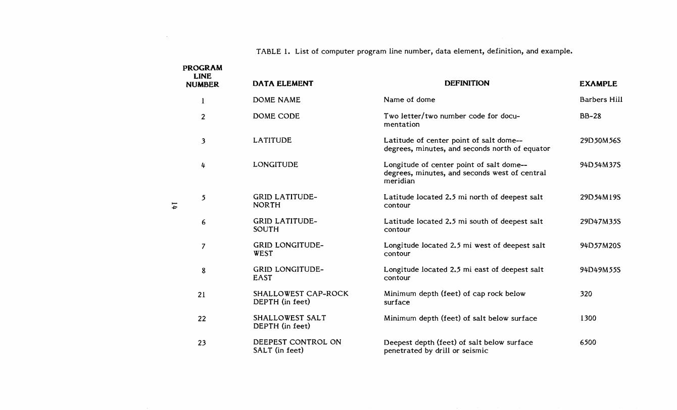
TABLE 1. List of computer program line number, data element, definition, and example.
PROGRAM LINE
NUMBER DATA ELEMENT DEFINITION EXAMPLE
I DOME NAME Name of dome Barbers Hill
2 DOME CODE Two letter/two number code for docu- BB-28 mentation
3 LATITUDE Latitude of center point of salt dome-- 29D50M56S degrees, minutes, and seconds north of equator
4 LONGITUDE Longitude of center point of salt dome-- 94D54M37S degrees, minutes, and seconds west of central meridian
5 GRID LA TITUDE- Latitude located 2.5 mi north of deepest salt 29D54Ml9S ...... NORTH contour -+:-
6 GRID LA TITUDE- Latitude located 2.5 mi south of deepest salt 29D47M35S SOUTH contour
7 GRID LONGITUDE- Longitude located 2.5 mi west of deepest salt 94D57M20S WEST contour
8 GRID LONGITUDE- Longitude located 2.5 mi east of deepest salt 94D49M55S EAST contour
21 SHALLOWEST CAP-ROCK Minimum depth (feet) of cap rock below 320 DEPTH (in feet) surface
22 SHALLOWEST SALT Minimum depth (feet) of salt below surface 1300 DEPTH (in feet)
23 DEEPEST CONTROL ON Deepest depth (feet) of salt below surface 6500 SAL T (in feet) penetrated by drill or seismic
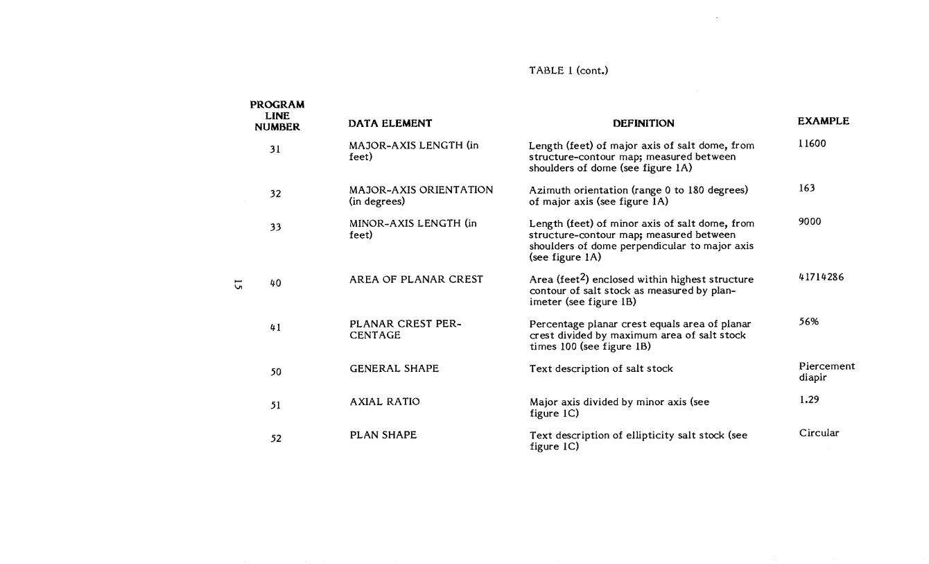
TABLE 1 (cont.)
PROGRAM LINE EXAMPLE
NUMBER DATA ELEMENT DEFINITION
31 MAJOR-AXIS LENGTH (in Length (feet) of major axis of salt dome, from 11600 feet) structure-contour map; measured between
shoulders of dome (see figure 1A)
32 MAJOR-AXIS ORIENT A TION Azimuth orientation (range 0 to 180 degrees) 163 (in degrees) of major axis (see figure 1A)
33 MINOR-AXIS LENGTH (in Length (feet) of minor axis of salt dome, from 9000 feet) structure-contour map; measured between
shoulders of dome perpendicular to major axis (see figure 1A)
..... 40 AREA OF PLANAR CREST Area (feet2) enclosed within highest structure 41714286 VI contour of salt stock as measured by plan-
imeter (see figure 1B)
41 PLANAR CREST PER- Percentage planar crest equals area of planar 56% CENT AGE crest divided by maximum area of salt stock
times 100 (see figure 1B)
50 GENERAL SHAPE Text description of salt stock Piercement diapir
51 AXIAL RATIO Major axis divided by minor axis (see 1.29 figure 1C)
52 PLAN SHAPE Text description of ellipticity salt stock (see Circular figure 1C)
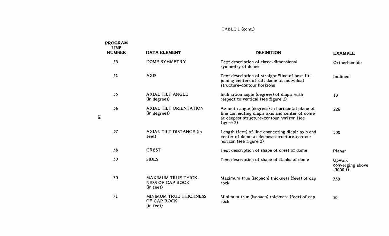
TABLE 1 (cont.)
PROGRAM LINE
NUMBER DATA ELEMENT DEFINITION EXAMPLE
53 DOME SYMMETRY Text description of three-dimensional Orthorhombic symmetry of dome
54 AXIS T ext description of straight "line of best fit" Inclined joining centers of salt dome at individual structure-contour horizons
55 AXIAL TILT ANGLE Inclination angle (degrees) of diapir with 13 (in degrees) respect to vertical (see figure 2)
56 AXIAL TILT ORIENT A TION Azimuth angle (degrees) in horizontal plane of 226 t-
(in degrees) line connecting diapir axis and center of dome 0\ at deepest structure-contour horizon (see
figure 2)
57 AXIAL TILT DISTANCE (in Length (feet) of line connecting diapir axis and 300 feet) center of dome at deepest structure-contour
horizon (see figure 2)
58 CREST T ext description of shape of crest of dome Planar
59 SIDES T ext description of shape of flanks of dome Upward converging above -3000 ft
70 MAXIMUM TRUE THICK- Maximum true (isopach) thickness (feet) of cap 750 NESS OF CAP ROCK rock (in feet)
71 MINIMUM TRUE THICKNESS Minimum true (isopach) thickness (feet) of cap 50 OF CAP ROCK rock (in feet)
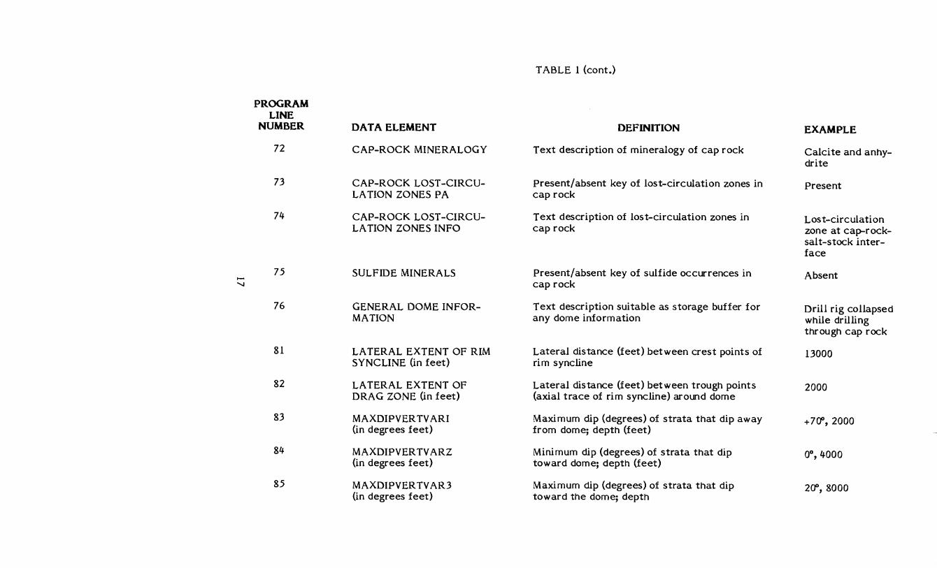
TABLE 1 (cont.)
PROGRAM LINE
NUMBER DATA ELEMENT DEFINITION EXAMPLE
72 CAP-ROCK MINERALOGY Text description of mineralogy of cap rock Calcite and anhy-drite
73 CAP-ROCK LOST -CIRCU- present/absent key of lost-circulation zones in Present LATION ZONES PA cap rock
74 CAP-ROCK LOST -CIRCU- Text description of lost-circulation zones in Lost-circulation LATION ZONES INFO cap rock zone at cap-rock-
salt-stock inter-face
75 SULFIDE MINERALS Present/absent key of sulfide occurrences in Absent >-
" cap rock
76 GENERAL DOME IN FOR- Text description suitable as storage buffer for Drill rig collapsed MATION any dome information while drilling
through cap rock
81 LA TERAL EXTENT OF RIM Lateral distance (feet) between crest points of 13000 SYNCLINE (in feet) rim syncline
82 LA TERAL EXTENT OF Lateral distance (feet) between trough points 2000 DRAG ZONE (in feet) (axial trace of rim syncline) around dome
83 MAXDIPVER TV ARI Maximum dip (degrees) of strata that dip away +7fY, 2000 (in degrees feet) from dome; depth (feet)
84 MAXDIPVER TV ARZ Minimum dip (degrees) of strata that dip OD,4000 (in degrees feet) toward dome; depth (feet)
85 MAXDIPVER TVAR3 Maximum dip (degrees) of strata that dip 2fY, 8000 (in degrees feet) toward the dome; depth
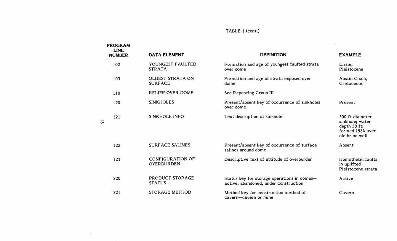
TABLE 1 (cont.)
PROGRAM LINE
NUMBER DATA ELEMENT DEFINITION EXAMPLE
102 YOUNGEST FAULTED Formation and age of youngest faulted strata Lissie, STRATA over dome Pleistocene
103 OLDEST STRATA ON Formation and age of strata exposed over Austin Chalk, SURFACE dome Cretaceous
110 RELIEF OVER DOME See Repeating Group III
120 SINKHOLES Present/ absent key of occurrence of sinkholes Present over dome
121 SINKHOLE INFO T ext description of sinkhole 300 ft diameter 0- sinkhole; water 00
depth 30 ft; formed 1984 over old brine well
122 SURF ACE SALINES Present/absent key of occurrence of surface Absent salines around dome
123 CONFIGURA nON OF Descriptive text of attitude of overburden Homothetic faults OVERBURDEN in uplifted
Pleistocene strata
220 PRODUCT STORAGE Status key for storage operations in domes-- Active STATUS active, abandoned, under construction
221 STORAGE METHOD Method key for construction method of Cavern cavern--cavern or mine
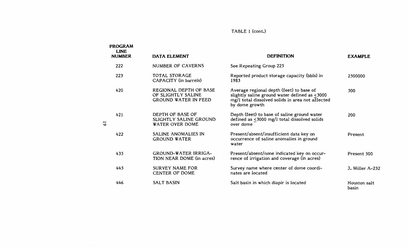
TABLE 1 (cont.)
PROGRAM LINE
NUMBER DATA ELEMENT DEFINITION EXAMPLE
222 NUMBER OF CAVERNS See Repeating Group 225
223 TOT AL STORAGE Reported product storage capacity (bbls) in 2500000 CAPACITY (in barrels) 1983
420 REGIONAL DEPTH OF BASE Average regional depth (feet) to base of 500 OF SLIGHTLY SALINE slightly saline ground water defined as ~3000 GROUND WATER IN FEED mg/l total dissolved solids in area not affected
by dome growth
421 DEPTH OF BASE OF Depth (feet) to base of saline ground water 200 SLiGHTL Y SALINE GROUND defined as ~3000 mg/l total dissolved solids ...... WATER OVER DOME over dome \D
422 SALINE ANOMALIES IN Present/absent/insufficient data key on Present GROUND WATER occurrence of saline anomalies in ground
water
435 GROUND-WATER IRRIGA- Present/absent/none indicated key on occur- Present 500 nON NEAR DOME (in acres) rence of irrigation and coverage (in acres)
445 SURVEY NAME FOR Survey name where center of dome coordi- J. Miller A-232 CENTER OF DOME nates are located
446 SALT BASIN Salt basin in which diapir is located Houston salt basin
N 0
10
PROGRAM LINE
NUMBER
10 - 11
34
34 - 35
34 - 36
60
60 - 61
60 - 62
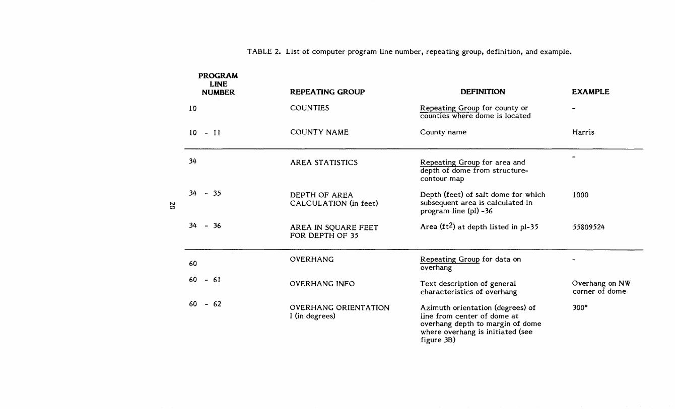
TABLE 2. List of computer program line number, repeating group, definition, and example.
REPEATING GROUP
COUNTIES
COUNTY NAME
AREA STATISTICS
DEPTH OF AREA CALCULA TION (in feet)
AREA IN SQUARE FEET FOR DEPTH OF 35
OVERHANG
OVERHANG INFO
OVERHANG ORIENT A TION I (in degrees)
DEFINITION
Repeating Group for county or counties where dome is located
County name
Repeating Group for area and depth of dome from structure-contour map
Depth (feet) of salt dome for which subsequent area is calculated in program line (pI) -36
Area (ft2) at depth listed in pl-35
Repeating Group for data on overhang
T ext description of general characteristics of overhang
Azimuth orientation (degrees) of line from center of dome at overhang depth to margin of dome where overhang is initiated (see figure 3B)
EXAMPLE
Harris
1000
55809524
Overhang on NW corner of dome
3000
N .-
PROGRAM LINE
NUMBER
60 - 63
60 - 64
60 - 65
60 - 66
90
90 - 91
90 - 91
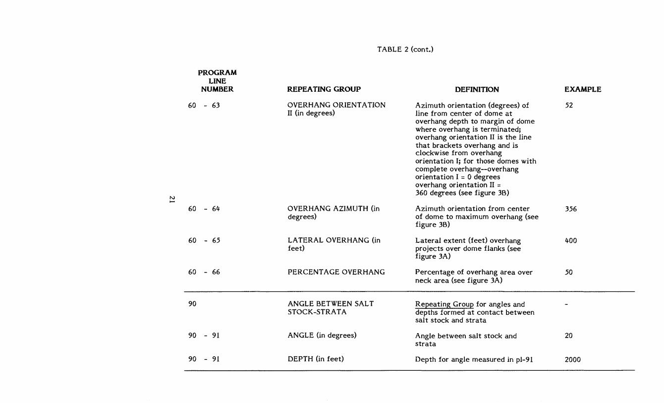
TABLE 2 (cont.)
REPEATING GROUP
OVERHANG ORIENTA nON II (in degrees)
OVERHANG AZIMUTH (in degrees)
LATERAL OVERHANG (in feet)
PERCENTAGE OVERHANG
ANGLE BETWEEN SALT STOCK-STRA T A
ANGLE (in degrees)
DEPTH (in feet)
DEFINITION
Azimuth orientation (degrees) of line from center of dome at overhang depth to margin of dome where overhang is terminated; overhang orientation II is the line that brackets overhang and is clockwise from overhang orientation I; for those domes with complete overhang--overhang orientation I = 0 degrees overhang orientation II = 360 degrees (see figure 3B)
Azimuth orientation from center of dome to maximum overhang (see figure 3B)
Lateral extent (feet) overhang projects over dome flanks (see figure 3A)
Percentage of overhang area over neck area (see figure 3A)
Repeating Group for angles and depths formed at contact between salt stock and strata
Angle between salt stock and strata
Depth for angle measured in pl-91
EXAMPLE
52
356
400
50
20
2000
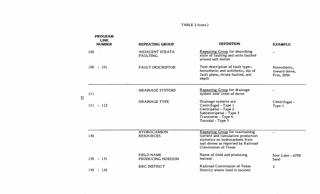
TABLE 2 (cont.)
PROGRAM LINE
NUMBER REPEATING GROUP DEFINITION EXAMPLE
100 ADJACENT STRATA Repeating Group for describing FAULTING style of faulting and units faulted
around salt domes
100 - 101 F AUL T DESCRIPTOR Text description of fault type-- Homothetic, homothetic and antithetic, dip of toward dome, fault plane, strata faulted, and Frio, 2000 depth
DRAINAGE SYSTEMS Repeating Group for drainage 111 system over crest of dome
N N
DRAINAGE TYPE Drainage systems are Centrifugal -111 - 112 Centrifugal - Type 1 Type 1
Centripetal - Type 2 Subcentripetal - Type 3 Transverse - Type 4 Toroidal - Type 5
HYDROCARBON Repeating Group for maintaining 150 RESOURCES current and cumulative production
statistics on hydrocarbons from salt domes as reported by Railroad Commission of Texas
FIELD NAME Name of field and producing Sour Lake - 6700 150 - 151 PRODUCING HORIZON horizon Sand
RRC DISTRICT Railroad Commission of Texas 3 150 - 152 District where field is located
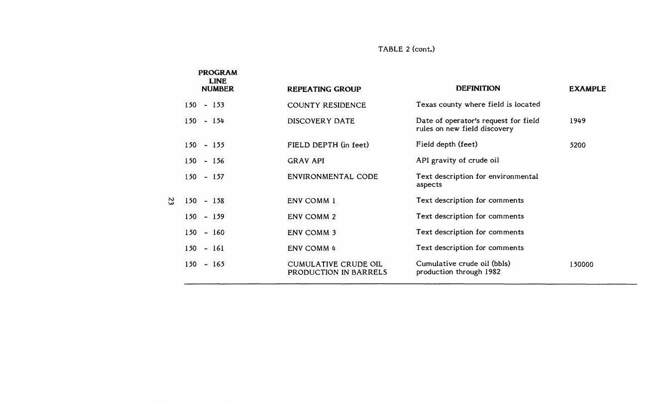
TABLE 2 (cont.)
PROGRAM LINE
NUMBER REPEATING GROUP DEFINITION EXAMPLE
150 - 153 COUNTY RESIDENCE Texas county where field is located
150 - 154 DISCOVER Y DATE Date of operator's request for field 1949 rules on new field discovery
150 - 155 FIELD DEPTH (in feet) Field depth (feet) 5200
150 - 156 GRAV API API gravity of crude oil
150 - 157 ENVIRONMENT AL CODE T ext description for environmental aspects
N 150 - 158 ENV COMM 1 Text description for comments I.N
150 - 159 ENV COMM 2 Text description for comments
150 - 160 ENV COMM 3 Text description for comments
150 - 161 ENV COMM 4 T ext description for comments
150 - 165 CUMULA TIVE CRUDE OIL Cumulative crude oil (bbls) 150000 PRODUCTION IN BARRELS production through 1982
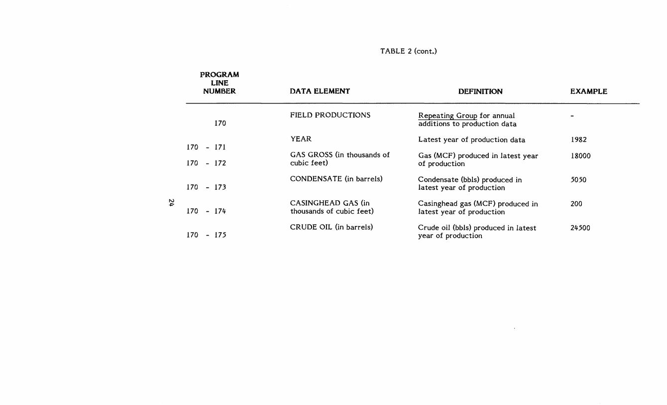
TABLE 2 (cont.)
PROGRAM LINE
NUMBER DATA ELEMENT DEFINITION EXAMPLE
FIELD PRODUCTIONS Repeating Group for annual 170 additions to production data
YEAR Latest year of production data 1982 170 - 171
GAS GROSS (in thousands of Gas (MCF) produced in latest year 18000 170 - 172 cubic feet) of production
CONDENSA TE (in barrels) Condensate (bbls) produced in 5050 170 - 173 latest year of production
N CASINGHEAD GAS (in Casinghead gas (MCF) produced in 200 ~
170 - 174 thousands of cubic feet) latest year of production
CRUDE OIL (in barrels) Crude oil (bbls) produced in latest 24500 170 - 175 year of production
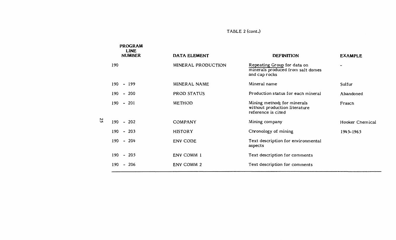
TABLE 2 (cont.)
PROGRAM LINE
NUMBER DATA ELEMENT DEFINITION EXAMPLE
190 MINERAL PRODUCTION Repeating Group for data on minerals produced from salt domes and cap rocks
190 - 199 MINERAL NAME Mineral name Sulfur
190 - 200 PROD STATUS Production status for each mineral Abandoned
190 - 201 METHOD Mining method; for minerals Frasch without production literature reference is cited
N VI 190 - 202 COMPANY Mining com pany Hooker Chemical
190 - 203 HISTORY Chronology of mining 1945-1965
190 - 204 ENV CODE Text description for environmental aspects
190 - 205 ENV COMM 1 Text description for comments
190 - 206 ENV COMM 2 Text description for comments
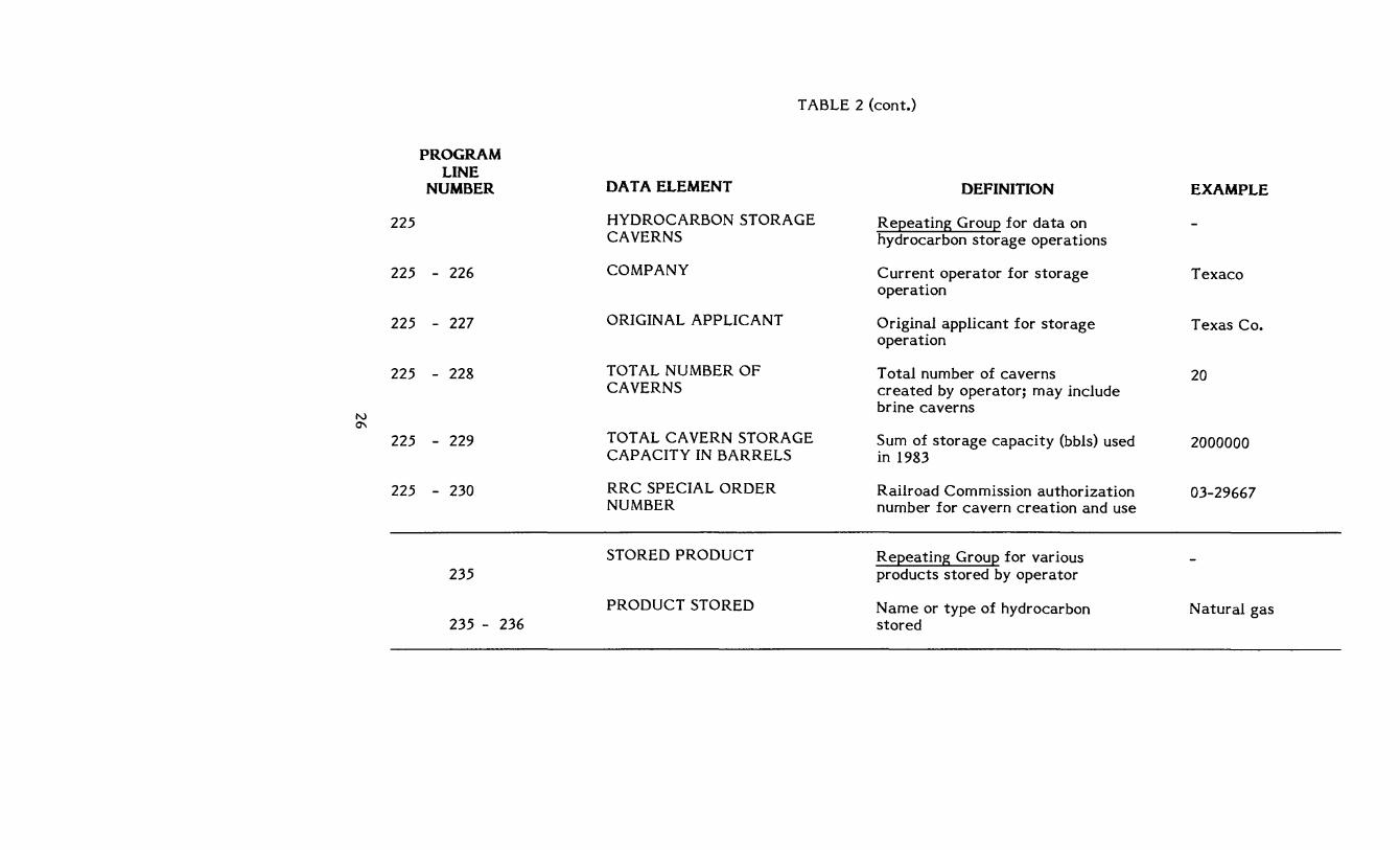
TABLE 2 (cont.)
PROGRAM LINE
NUMBER DATA ELEMENT DEFINITION EXAMPLE
225 HYDROCARBON STORAGE Repeating Group for data on CAVERNS hydrocarbon storage operations
225 - 226 COMPANY Current operator for storage Texaco operation
225 - 227 ORIGINAL APPLICANT Original applicant for storage Texas Co. operation
225 - 228 TOTAL NUMBER OF Total number of caverns 20 CAVERNS created by operator; may include
brine caverns N 0"\
225 - 229 TOTAL CAVERN STORAGE Sum of storage capacity (bbls) used 2000000 CAPACITY IN BARRELS in 1983
225 - 230 RRC SPECIAL ORDER Railroad Commission authorization 03-29667 NUMBER number for cavern creation and use
STORED PRODUCT Repeating Group for various 235 products stored by operator
PRODUCT STORED Name or type of hydrocarbon Natural gas 235 - 236 stored
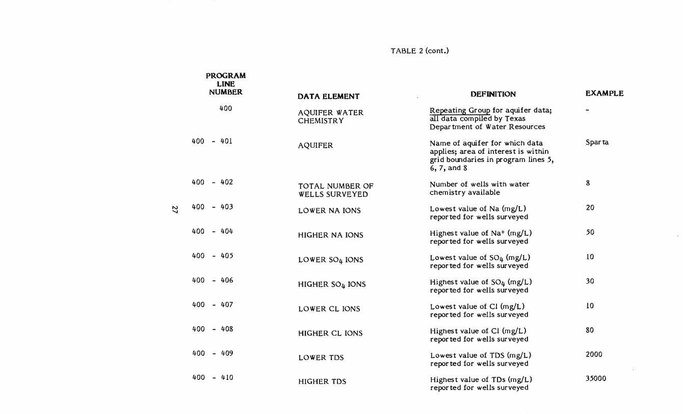
TABLE 2 (cont.)
PROGRAM LINE
NUMBER DATA ELEMENT DEFINITION EXAMPLE
400 Repeating Group for aquifer data; AQUIFER WATER CHEMISTRY all data compiled by Texas
Department of Water Resources
400 - 401 Name of aquifer for which data AQUIFER Sparta applies; area of interest is within grid boundaries in program lines 5, 6,7, and 8
400 - 402 TOT AL NUMBER OF Number of wells with water 8
WELLS SURVEYED chemistry available
N 400 - 403 '-I LOWER NA IONS Lowest value of Na (mg/L) 20
reported for wells surveyed
400 - 404 HIGHER NA IONS Highest value of Na+ (mg/L) 50 reported for wells surveyed
400 - 405 Lowest value of S04 (mg/L) LOWER S04 IONS 10 reported for wells surveyed
400 - 406 HIGHER S04 IONS Highest value of S04 (mg/L) 30
reported for wells surveyed
400 - 407 LOWER CL IONS Lowest value of Cl (mg/L) 10 reported for wells surveyed
400 - 408 HIGHER CL IONS Highes t value of Cl (m gIL) 80 reported for wells surveyed
400 - 409 LOWER TDS Lowest value of TDS (mg/L) 2000 reported for wells surveyed
400 - 410 HIGHER TDS Highest value of TDs (mg/L) 35000 reported for wells surveyed
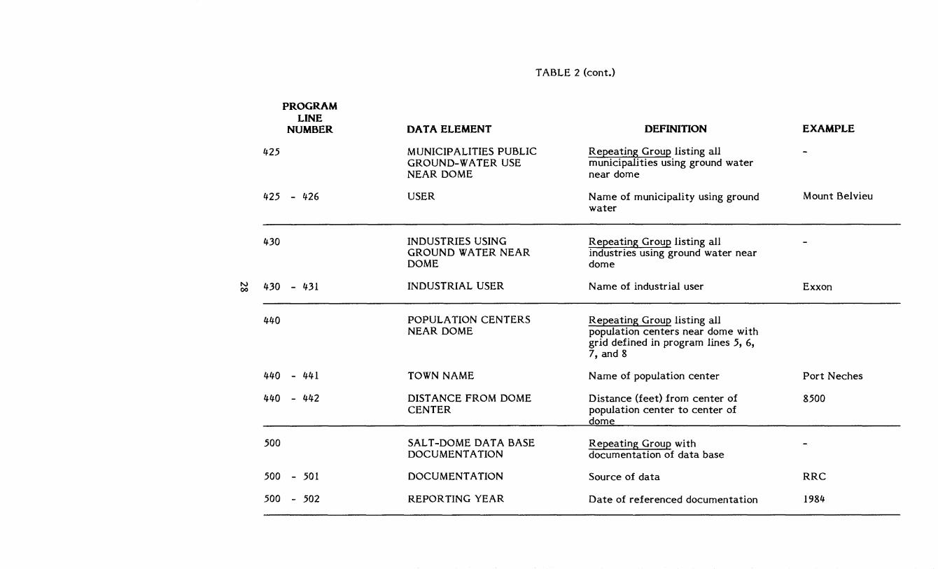
TABLE 2 (cont.)
PROGRAM LINE
NUMBER DATA ELEMENT DEFINITION EXAMPLE
425 MUNICIPALITIES PUBLIC Repeating Group listing all GROUND-WATER USE municipalities using ground water NEAR DOME near dome
425 - 426 USER Name of municipality using ground Mount Belvieu water
430 INDUSTRIES USING Repeating Group listing all GROUND WATER NEAR industries using ground water near DOME dome
N 430 - 431 INDUSTRIAL USER N arne of industrial user Exxon 00
440 POPULA TION CENTERS Repeating Group listing all NEAR DOME population centers near dome with
grid defined in program lines 5, 6, 7, and 8
440 - 441 TOWN NAME N arne of population center Port Neches
440 - 442 DIST ANCE FROM DOME Distance (feet) from center of 8500 CENTER population center to center of
dome
500 SALT-DOME DATA BASE Repeating Group with DOCUMENT A TION documentation of data base
500 - 501 DOCUMENT A TION Source of data RRC
500 - 502 REPOR TING YEAR Date of referenced documentation 1984
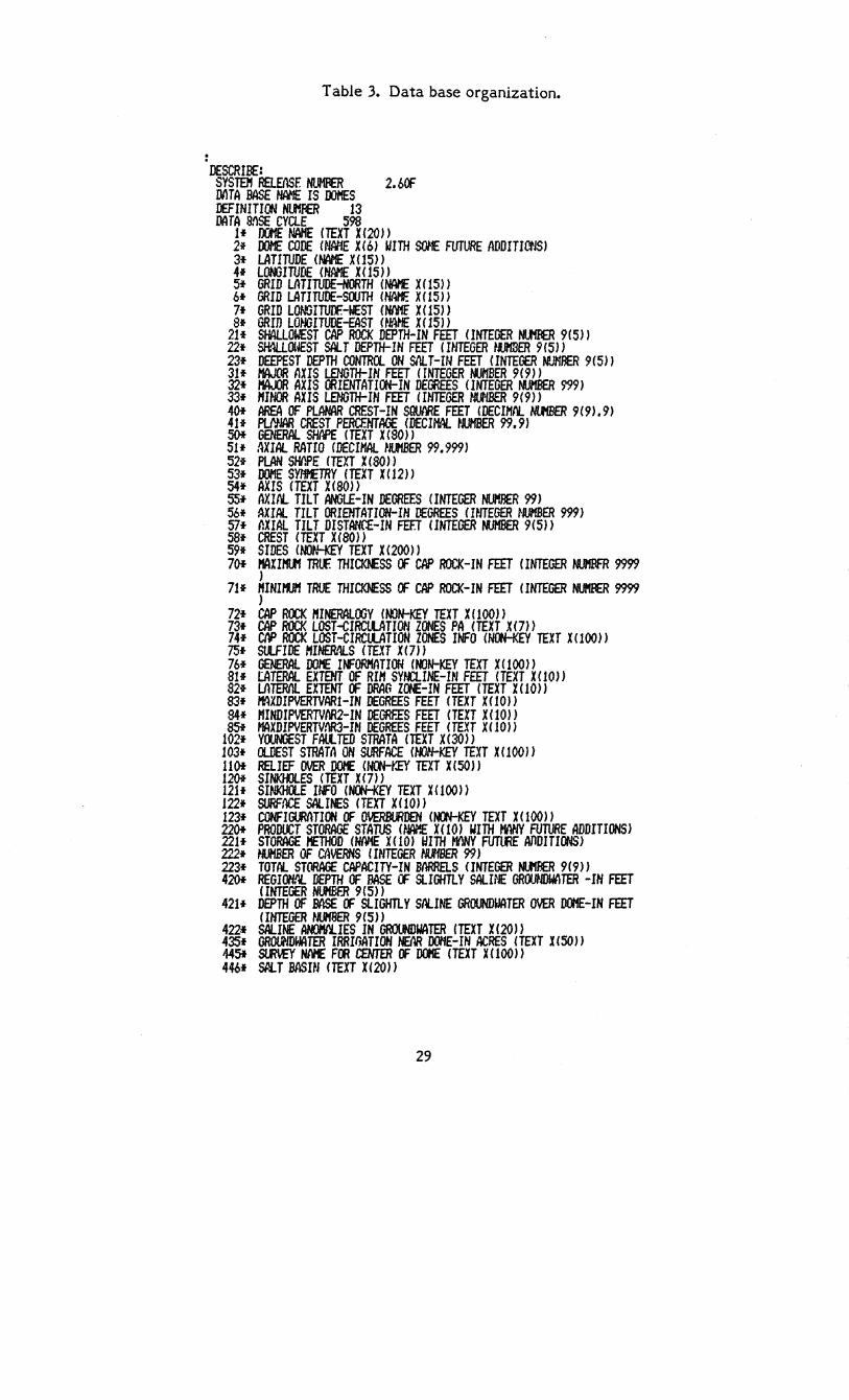
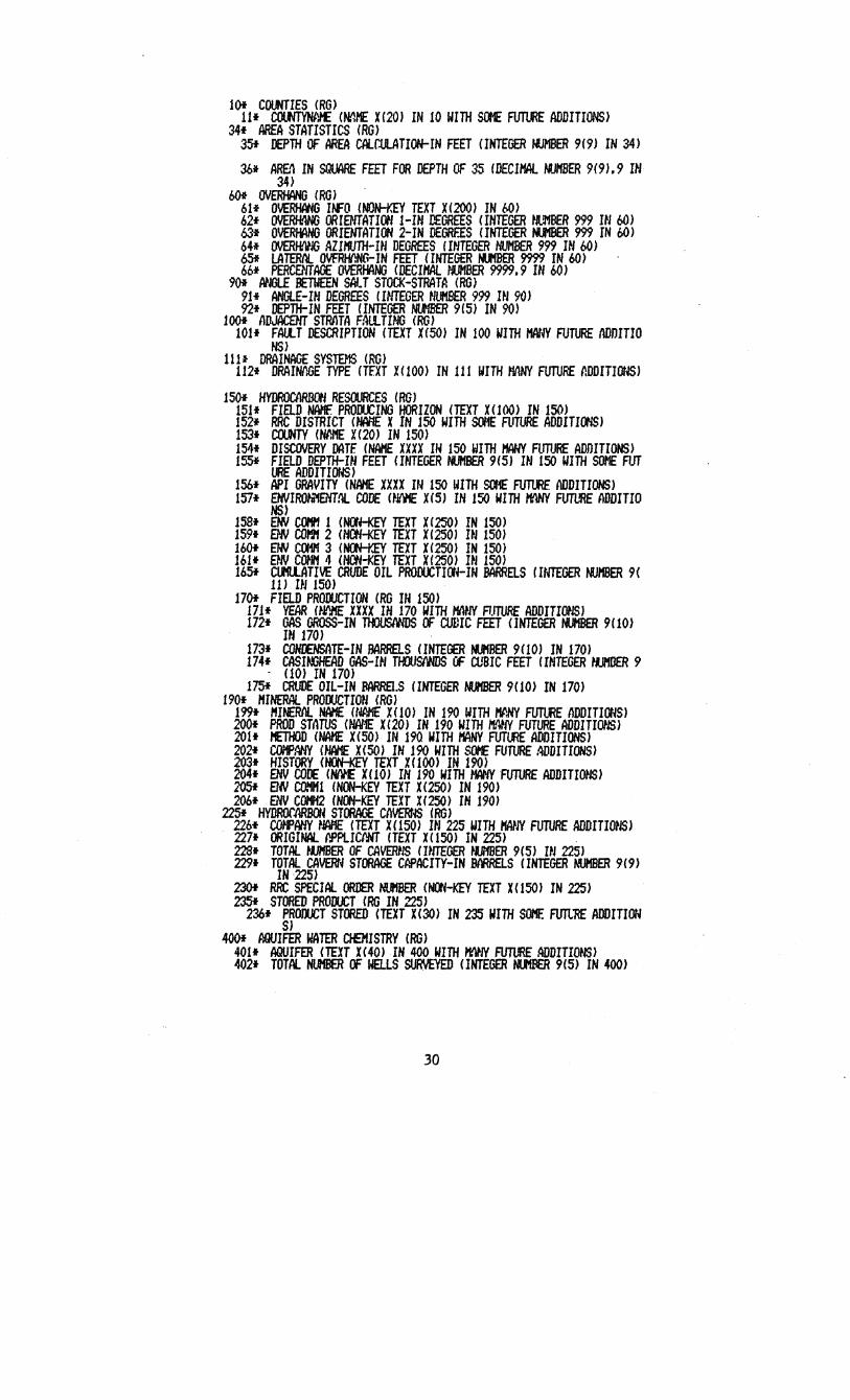
Table 3. Data base organization.
DESCRIBE: SYSTEI'f REI..EIlSF. NUMFIER 2. b(1= MTA BASE HAi'1E IS OOMES DEFINITION NUMBER 13 DATA SllSE CYClE 598
1* J)()IE NAME (TEXT XC 20 ) ) 2* DOME CODE (HME X(6) WITH StJI'IE FUTURE IlDDITICNS) 3* LATIruDE (f'W'E X(15» 4* LOMJIruDE <NAME X(15» Sf GRID LATIruDE-NORTH (NAI1E X(lS» 6* GRID LATIruDE-SOOTH (NAf1F. X(15» 7f GRID LOMJIruN:-WEST (NI'll1f X ( 15) ) Sf GRID LO~ITUDE-EAST (NAHE X (15) )
21* SHALLOWEST CAP ROCK DEPTH-IN FEET <INTEGER NIJ1fIER 9(5» 22* SH:U.OUEST SALT DEPTH-IN FEET mlTEGER tmER 9(5» 23* DEEPEST DEPTH CONTROL ON SliLT-IN FEET <INTEGER N!.JMRER 9(5)) 31* I1AJOR lUIS LENGTH-IN FEET (rNTEGER NUI1BER 9(9» 32* /'IAJJR AXIS ffiIENTATICH-IN DEffiEES (INTEGER MJl1BER m) 33f I'/IHOR AXIS LENGTH-HI FEET (INTEGER NlJ'/BER 9(9» 40f AREA OF PLANAR CREST-IN SQUARE FEET (DECIM. NltfBER 9(9).9) 41f MlAR CREST PERCENTAGE (DECIMAL tlUHBER 99.9) 50* GENERAL SHAPE (TEXT X(80» 51* AXIAl.. RATIO (DECIMAL tlUMBER 99.999) 52* PLAN SHIlPE (TEXT X(SO)) 53* DOME S'M£TRY (TEXT X ( 12)) 54* AXIS (TEXT X(SO» SS* AXlrL TILT ANGLE-IN DEGREES (INTEGER NUI1RER 99) 56* AXIAl.. TILT ORIENTATION-IN DEGREES (WTEGER NUMBER 999) 57t ~XIAL TILT DISTANCE-IN FEET (INTEGER NUHBER 9(5» 58* CREST (TEXT X(80}) 59* SIDES (NOtLKEY TEXT X(2OO)} 70t KAXIM TRlf THIClOESS OF CAP ROCK-IN FEET <INTEGER NIJfBFR 9999
} 71* MINIM TRUE THloo.ESS OF CAP ROCK-IN FEET (INTEGER NIJ/II11ER 9999
) 72t CAP ROCK JIIINERALOOY (t.tJN-KEY TEXT X (100)) 73t CAP ROCK LOST-GZRCllATIOtI ZONES PA (TEXT X (7) ) 74* eN> ROCK LOST-CIRCllATIOH ZONES INFO (NOO-KEY TEXT X(100}) 1St StlFIDE MINERllLS (TEXT X (7) ) 76* GENERAL DOI1E IN=ORI'IIlTIOU (MJN-KEY TEXT X(100» 81f tATERAL EXTENT OF RIM SYNCLINE-IN FEET (TEXT X(10}) S2f LlHER/IL EXTENT OF DRAG Z(JE-IN FEET (TEXT X (10) } 83f MXDIPVERTVARI-IN DEGREES FEET (TEXT XOO» 84* I'fINDIPVERTVftR2-IN DEGREES FEET (TEXT X(10)} 8Sf MAXDIPVERTVM3-IN DEGREES FEET (TEXT X ( 10))
102* YOUNGEST FAULTED STRATA (TEXT X(30)} 103* OLDEST STRATA ON SURFACE (tDI-KEY TEXT X(1OO)} 11 Of RELIEF OVER DOI£ (NOO-Y.EY TEXT X (50) } 1201 SINKflILES (TEXT X (7)) 121* SINKHOLE INFO (Nat-KEY TEXT X(100» 122* SURFACE SALINES (TEXT X(10» 123f CONFIGlMTION OF OVERBtRDEN (~KEY TEXT X(1OO» 2201 PRODOCT STORAGE STArus (~M X(10) WITH HIlHY FUruRE ADDITIONS) 221* STORAGE t1ETHOD (NME XC 10) WITH mNY FUTffiE AIlDITI(m} 222* WiDER OF CAVERNS (INTEGER tUfBER 99) 223* TOTAL STORAGE CAPACITY-IN MRRaS <INTEGER NltIffER 9(9» 4201 REGION.~ DEPTH OF BASE CF SlIGHTLY SALINE GROOtIDUATER -IN FEET
(INTEGER NUHBER 9(5» 421* DEPTH OF BASE OF SlIGHTLY SIlLINE GROUNDWATER OVER DOME-IN FEET
<INTEGER ~lIH'8ER 9(5)} 422* SAlINE AMJI'IIlLIES IN GROUNDWATER (TEXT X(20}) 435* GRQU\lDWATER IRRIfJATION HEM DOME-IN ACRES (TEXT %(50)) 4451 Slm£Y NIVfE Fm CENTER OF DOI'fE (TEXT XC 100) ) 446f SP.I..T BASItI (TEXT X(20)}
29
lOt COUNTIES (RG) 11* COI.M'YtW£ (~HE H2O) IN 10 WITH SM FUTURE ADDITIONS)
34* AREA STATISTICS (RG) 35* DEPTH OF AREA CAlr.tJLATION-IN FEET CINTEGER MJMBER 9(9) IN 34)
30* ARE'! IN SQUARE FEET FOR DEPTH OF 35 (DECIHAl.. "Jl'lBER 9(9).9 IN 34)
bOt OVERHANG (RG I 61* OVERHANG UFO (NON-Y.EY TEXT X(2001 IN bO) 62* 0YERH.4NG ORIENTATION l-HI DEGREES (INTEGER ~UlBER 999 m 60) 63* OVERHANG ORIENTATION 2-IN DEGREES (INTEGER tUIBER m IN 60) 64* OVERf-WJG AZIMIJTH-nl DEGREES (INTEGER NUMBER 999 IN 60) b5* LATERnL OVFRHIlNCr-IN FEET (INTEGER M.tfBER 9999 IN 60) 66* PERCENTAGE OVERI-VlNG (DECII1AL HU11BER 9999.9 HI 60)
90* ANGLE BETWEEN SALT STOCK-STRATA (RG) 91* ANGLE-HI DEGREES (INTEGER NUMBER 999 HI 90) 92* DEPTH-IN FEET (INTEGER NlIIBER 9(5) IN 90)
100* IIDJAWIT STRATA F~ltTING (RG) 101* FAlU DESCRIPTION (TEXT X(SO) IN 100 WITH t1ANY FUTURE IIDDITIO
NS) 111~ DRAINAGE SYSTEMS (RG)
112* DRAINnGE TYPE (TEXT X(100) IN 111 WITH MANY FUTURE ~DDITIm~)
150* HYDROCIlRW'1 RESOURCES (RG) 151* FIElD NAME PROIX.CING HORIZON (TEXT Hl(0) IN 150) 152* RRC DISTRICT (HAi-tE X IN lSO WITH SOfiE FUTURE ADDITIcm) 153* Cll.t4TY (Nl':/'fE H20) IN ISO) 154* DISCOVERY MTF. (NA/'fE XXXX IN ISO WITH I1AHY FlmJRE ADIHTIONSI 155f FIELD DEPTH-IN FEET mlTEGER NltIBER 9(5) HI 150 WITH SOME FlIT
lIRE ADDJTIor~) 156* API GRAVITY (NM XXXX IN 150 WITH SOME ~ IIDDITIONS) 157* ENVIROhI"iENT!lL. CODE (~JI\HE XeS) IN 150 WITH H!lNY FI.ITlflE IIDDITIO
NS) 158* aN COIf1 1 (NCfH<EY TEXT X(250) IN 150) 159* aN COI".H 2 CNCN-KEY TEXT X(2S0) HI 150) 160t eN ca1l'l 3 (Nat-Y.EY TEXT X (250) IN 150) 161* E~N COHM 4 (NCN-KEY TEXT X(250) HI 150) 1651 Clf'IllATIVE CRUDE OIL PRODUCTICtt-IN BARRELS (INTEGER NUtlBER 9(
11) HI 150) 170t FIElD PRODUCTION (RG m ISO)
171* YEAR (~IfIJfE XXXX HI 170 WITH toWN FUTURE ADDJTI~JS) 172* GAS GROSS-IN 1l«llISIWDS OF CUDIC FEET (INTEGER NUHBER 9(10)
m 170) 173* CONr£NSATE-IN BARRaS (INTEGER MJfBER 9(10) IN 170) 174* CASIMJHEAD GAS-UI 1lOOSIINDS OF CUSIC FEET fINTEGER ~U/'fDER 9
- (10) IN 170) 175* CRUDE OIL-IN BARREl.S (INTEGER NUI'IBER 9(10) IN 170)
190* MINERAl PROOOCTION (RG) 199* MI~ NAME (tWlE HI0) IN 190 WITH /'ff:NY FlI1'lRE ADDITIONS) 200f PROD smrus (NAl-1E X(20) IN 190 WITH I'fAm FUTURE ADDITI~lS) 201* METHOD (NAME X(SO) IN 190 WITH /'IANY FUTlRE ADDITIONS) 202* COif'flHY (~JAHE X(SO) IN 190 WITH SOME FlITURE ~DITIONS) 203* HISTORY (NftKE'( TEXT X(1OO) IN 190) 204* ENV CODE (HfIl'E X(10) IN 190 WITH MAHYFUTURE ADDITIIlJS) 2051 8fJ COMlfl (NON-KEY TEXT X(2SO) IN 190) 206* ENV COMH2 (N(tl-KEY TEXT X(2SO) IN 190)
22Sf HYDROfMBOH STa1AGE CAVERNS (00) 226* mpAHY ~WIE <TEXT X(150) IN 225 WITH ~N FUTURE ADD1TI~JS) 227* a1IGINAI.. I'PPlICIlNT <TEXT X<1SO) IN 225) 228* TOTAl tlJ/'lBER OF CAVER~lS (nlTEGER tlJMBER 9(5) HI 225) 229* TOTAl. CAVERN STORAGE CAPACITY-IN BARRELS (INTEGER MHlER 9(9)
IN 225) 230t RRC SPECIAl. ORDER NUl'lBER (N(t4-KEY TEXT X<lSO) IN 225) 235f STORED PROOOCT (RG IN 225)
236* PROJlICT STORED (TEXT X(30) IN 235 WITH SM FUTl'RE ADDITION S1
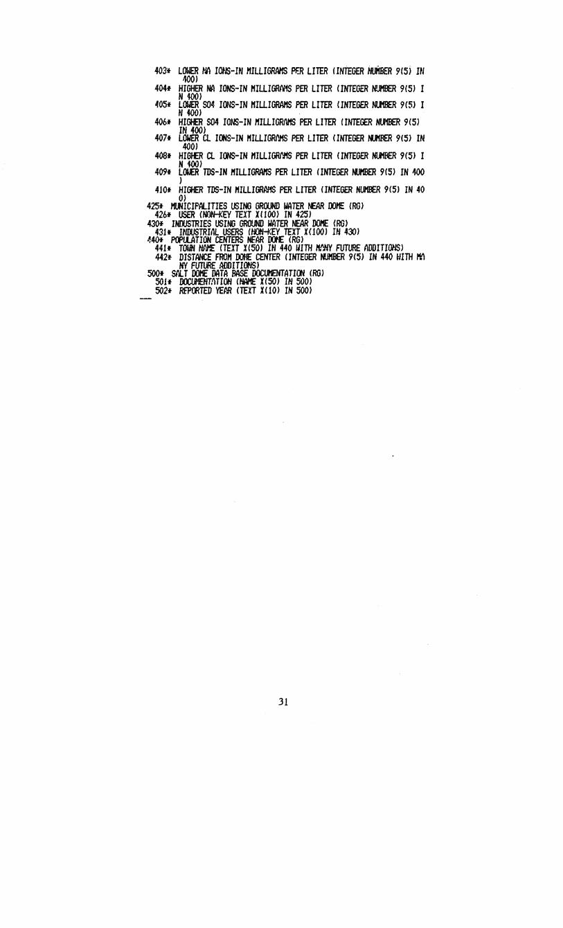
400f AQUIFER WATER CJetISTRY (RG) 401* AQUIFER (TEXT X(40) IN 400 WITH ~IY FUTURE ADDITIONS) 402* TOTAL NUMBER OF taLS SURVEYED (INTEGER NltIBER 9(5) IN 400)
30
403* LOWER ~i1 lOtS-HI I1IlLIGRAMS PF.R LITER !INTEGER HUifBER 9(5) HI 40{»
404* HIGHER NA IONS-IN HIllIGRlViS PER LITER (INTEGER N!JHBER 9(5) I N iOO)
405* LOWER S04 IONS-IN HIllIGIWIS PER LITER <INTEGER NltfBER 9(5) I tl 400)
406* HIGHER S04 IONS-IN /'fIllIGRf\l'IS PER LITER (INTEGER NU1BER 9(5) IN 400)
407* LOWER Cl ICt4S-IN HIllIGRI'.HS PER LITER (INTEGER MJfBER 9(5) IN 400)
4OS* HIGI£R Cl IONS-IN /'fIllIGRi'J'IS PER LITER <INTEGER NltfFIER 9(5) I N WO)
409* L(lI..ER TDS-IN /'fIllIGRAMS PER LITER (INTEGER MJI1BER 9(5) IN 400 )
410* HIGHER TDS-IN HIllIGRf11iS PER LITER (INTEGER NUHBER 9(5) IN 40 0)
425* MUNICIPAlITIES IJSING GROOND WATER ~ DOI1E (RG) 426* USER (NOtH<EY TEXT X(100) IN 425)
430t INOOSTRIES USING GRO!JND WATER NEAR DOHE (RG) 431* UIDUSTRIIlL USERS (NON-KEY TEXT X(100) HI 430)
.,401 POPtlATION CENTERS NEAR 00'£ (RG) 441* TOWN ~~ (TEXT X(50) IN 440 WITH H~Y FUTURE ADDITIONS) 442f DISTANCE FRO" 00f1E CENTER (INTEGER tUIBER 9(5) IN 440 WITH P1!\
NY FUTURE ADDITIONS) SOOt SI'IlT 00l1E DATA BASE DOCUI'IENTATItw eRG)
50 if DOCtJ'IENT:1 HON (NAME xc 50) IN 500) 502* REPOOTED YEM (TEXT X(10) IN 500)
31
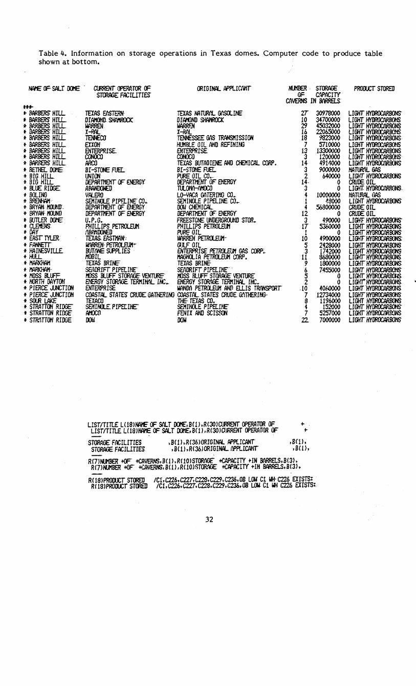
Table 4. Information on storage operations in Texas domes. Computer code to produce table shown at bottom. .
~ OF SALT WE .
H+-*" BARBERS" HILL ,. BARBERS HILL ;to ~'.RBERS HILL • UARBERS" HILL • MRBERS HILL • BARBERS HILL ,. BARFERS HILL ,. BARBERS HILL -it BARfmr HILL ,. arna. OIJE :t BrG HILL *' BIG HILL *" RUE RImE *" BOLING *' BREMiAM· *" BRYAN. HOOr-lU" *' BRYAN MOON£) • BUTLER OO'E • ClEl£HS • DAY *' EASTTYlEt *' FAH1£TT *' HAII£SVILLE. f HULL *' I1ARI<HAH • MAAl<}Wf-*' MOSS BllFF *' NORTH DAYTCH .. PIERCE JJOCTICW • PIERCe J.fiCTIOH *' S{)tR" L.AI<E *' STRATTG'l RIDGe *' STRATTON RInr~ f STR.I\TTOH RlOOE
ctflRENr Il'ERf:TOR OF OOraIWL APPlICANT Nltf1:1ER. STowa: STORAGE F;CIUTI~ OF c.1PnCIT'f
Cl\VERNS IN 8MREI.S.
TEXAS B':STERH- TEXAS NA"MI'L GI'.5OC!NE 2T OrAHOMl. SI-WIROClC o ImJND SHMROCK 10 WMREN·. WAARF.N ;:?" X-RAl X-ML 16 TENf£W TEN1£SSEE GAS TRANSl1ISSIOH 18 EXXOH HUH8lE Ole I\HO REFIHUjJ 7 ENTERPRISE. OOERPRISE 13 cetml COMXO 3 ARCO TEXAS BUTADIENE AHD cr£MICAI.. CORP. 14 Bf -STat FUEL BI -STOtE FUEr:.. 3 UNI~ P~ OIL CO.- 2 IEPARTMEHr OF eNERGY DEPART1'e1T OF El'lERGY 14· AFAHOOIED ntOO'HY1OCO 3 Vfi.ERO LD-VACA Gf'lTERIHG CO .. " samn£ PIPFI.lNE co .. SEHIMll PIP8...ItE. COo- l OE.DAROOrr OF e£RGY roo OlEMlCAL 4 Df.PARm:NT OF amy IJEPARMHr (F ENERGY 12 U.P.G •. FREESTOt£. UNIlERGRtlJHD STORr 3 F1HLLIPS PETROl.ElJi; PHILLIPS PtTROtEI11 17 :iBP,tlOONED PURE" OIL 1 TEXAS. Ef'.smlH': IIAAREN PETRCl£TJ1- 10 Uf\RRel: PETRct.Etm'" IJJLF OIL S BfJTfflE SlfPlIES " ENTERPRISE P£TRIl.E1J1 GAS COR?;. 3 MOBIL l1A('iIClIA PETRIl..£UH CtJRP. 11 TEXAS BRI£ TEXAS BRINE 9 SEt1ffiIFr PIPEtINf: SEI\OOIFT PlPELIliE" 6 nJSS BLLfF STOOfIGE 1JEH1U£' ItJSS lUfF STORAGE' YENT'fJ1£ S ENERGY STtlt~ TERHI~ 11£ .. ENERGY STOR.'1C£ TERMUlAL IPIC. 2 8-fTERPRISE WNIDI\ PETIUEl.JH ANn ELLIS TRIlNSPORT .10 COASTAL STATES" CRUDE GATHERIOO COASTIlL STATES CRUDE. G!\nERUJG- 7 TEXACO THE· TEXAS CO~ S satHRE PIPErINE" samru. PIPELUe- i AHOCil FENIX MID SCI~ 7 00ti DOW 22-
LISTITrTL£ LClS1~ OF SilT OCt£,BW,R(3I)ICl..flRENT OPERATOR OF + LISTITITLE LC18lHAME OF SALT OO'£,B(ll,R(30>CIJRROO OPERATOR CF +
STORAGE FOCIUTrES ,B(1},R(361ORIGINAL APptICANT ,B<11, ST~ FACIUTIES .B(1),R(36)ORIGINAL.:mlCAHT .BCLl.
R(71~ +OF +CAVERNS,B(1),RClOlSTORtlGC +CAPACrTY +IN BMRElS.B(31, R(7)MJf8ER +CF +CAVERNS,B(1)'R(10)~TOR.~ +CAPACITY +IH BAARELS.B(3l ..
3097S000 34700000 45032()()() 22065000
9323000 5710000
13300000 1200000 491~ 9000000
b40000 0 0
10000000 ~oooo
s:,8ooo00 0
490000 S360000
0 4900000 2428000 1742000 S6SOOOO lSOOOOO 745S000
0 0
40f.OOOO 12734000
119601)() 152000
5257000 7000000
R<1S)PROOCCT STORED ICl,C226.C22T.CL..."S.C229,C236.0B LI)l Ct IrJH- C226 EXISTS: RIlS)PROru:r STORED IC1.C2.26,C22T.C22S.C229.C230.OB Low. Cl Iii C226 EXISTS:.
32
PROLtcr STORED
LIGHT H'fDROCAA8OO" LIGHT HYDROC.~OHS LIGHT HYIlROCMRONS LIGfr HYDROCARBOO LIGHT HYmOCIlRBOOS" L!Grr~lS LIGHT HYDROCARBONS LIGHT~lS LIGHT HYDROCIlRBONS HATUR.1L GAS LIGHT HYDROCARIn'S CRUDE OIL LIGif HYDROCI'oROCWS ~lAMAL GAS LIGHT HYOOOCARroNS CRUDE OIL CRUrE OIL LIGHT HYlJROCARl3(ffl LIGHT H'fDROCAA8OO" LIGHT HYIlROCt.ROONS LIGHT~ LIGHT" HYmOCARroHS LIGHT"~ LIGHr~ LIGfr HYDROCM.OONs: LIGHT HYDROCARBCNS LIGHT HYmOCAR.BCt-5 L!GHr H'fIlROCAARO\lS LIGHT 'HYmOCAROO'~ LIGHt HYlJROCARl3(ffl LIGHT HYmOCARBIJS LIGHT HYmOCARBOO) L1GiT H'f1JtOC.MOOHS LIGHT HYmOCARBlJHS
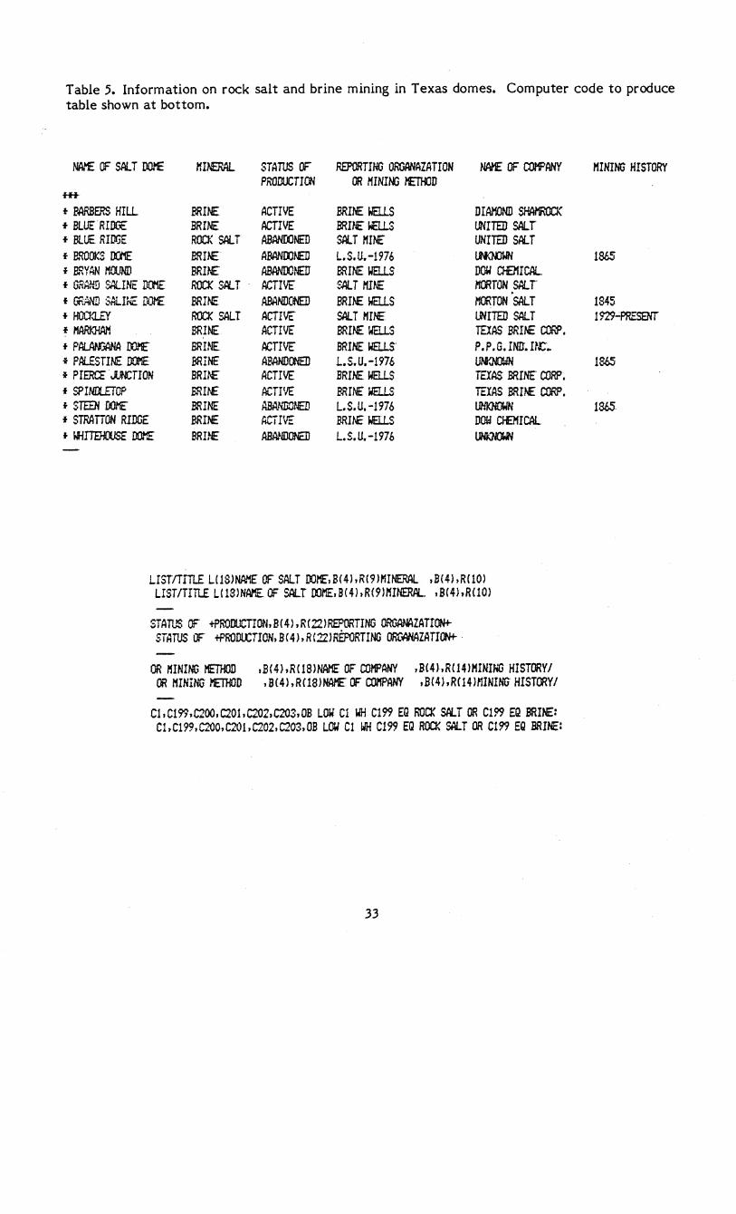
Table 5. Information on rock salt and brine mining in Texas domes. Computer code to produce table shown at bottom.
NAtt£ OF SALT DOME XI~ STATUS OF REPORTING ORGANAZATION lWE OF COl'f'ANY PRODUCTICW OR MINING /'ETHOD
H+
f BARBERS HILL MINE ACTIVE MINE WELLS DIAMOND SHAHROClC + BLUE RIDGE MINE ACTIVE BRn£~S UNITED SALT + BLUE RIDGE ROO~ SALT ABANOONED SALT MINE" UNITED SALT f B.croOKS 00'1E BRnE ABANOO~ L.S.U.-1976 l.N<mWN f BRYAN MClJND BRI~ ABANOO~lEU BRINE WELLS DOW CIeIICAL + GRHl-'.!i SALINE ~E ROCK St:LT ACTIVE SALT MINE /'IOiTON SAl. T f GRAND SALINE DOl'E BRINE ABANDC~ BRINE WELLS MORTON SALT f HOOa..r.-V ROCK SALT ACiIVE SALTMH£ lRiITED SALT + MARKHA/'i BRINE ACTIVE' BRINE waLS TEXAS MINE CORP. f PAI..JW:ANA 00.1£ BRINE ACTIv'E BRINE WillS P. P. G. HID. n~ .. f PALESTIl£ DOME BRINE AF.ANDONED L.S.U.-1976 uw.NO'JN f PIEROr"JUNCTION BRn£" ACTIVE BRINE WELLS TEXAS BRINE CORP. f SPINDlETOP ERnE ACTIVE BRINE" WELLS TEXAS BRINE CORP. f STEEN DOH[ BRINE HBA.NDOt-./ED L.S.U. -1976 l.IHKNOWN f STRATTON RIDGE BRINE ACiIVE MIte WELLS DOW CI-El'IICAL f IflITEHOOSE DOME BRINE AB~IDONED L.S.U.-197b ~
LISTITITLE UlS)NAI'IE OF SAlT DOME,B(4),R(9)I'IINERAl ,B(4),R(10) LIST/TITLE U13)NAME. OF SALT OO/'IE,B(4),R(911'IINERPL ,B(4),RClO)
STATUS OF tPRODUCTION,B(4),R(22JREPORTING ORGANAZATr~ STATUS OF tPRODUCTION,B(4),R(22)REPoRTING ORC~ZATrON+
OR MHlING I'IETHOD ,B(4),R(lS)NAME OF COMPANY ,B(4),RC14)HINING HISTORYI OR MININU l'ETHOD ,B(4J,Rf18)NAME OF CO/'IPANY .B(4),RC14H1INING HISTCJlYI
Cl,Cl99,C200,C201,C202.C203.0B LOW Cl WH Cl99 EG ROCK SALT OR Cl99 EG BRINE: Cl.C199,C2QO,C201,C202.C203,OB lOW Cl WH C199 EG ROC!{ SALT OR Cl99 EQ BRINE:
33
MINING HISTORY
1865
1845 1929...;PRESENT
1865
1865
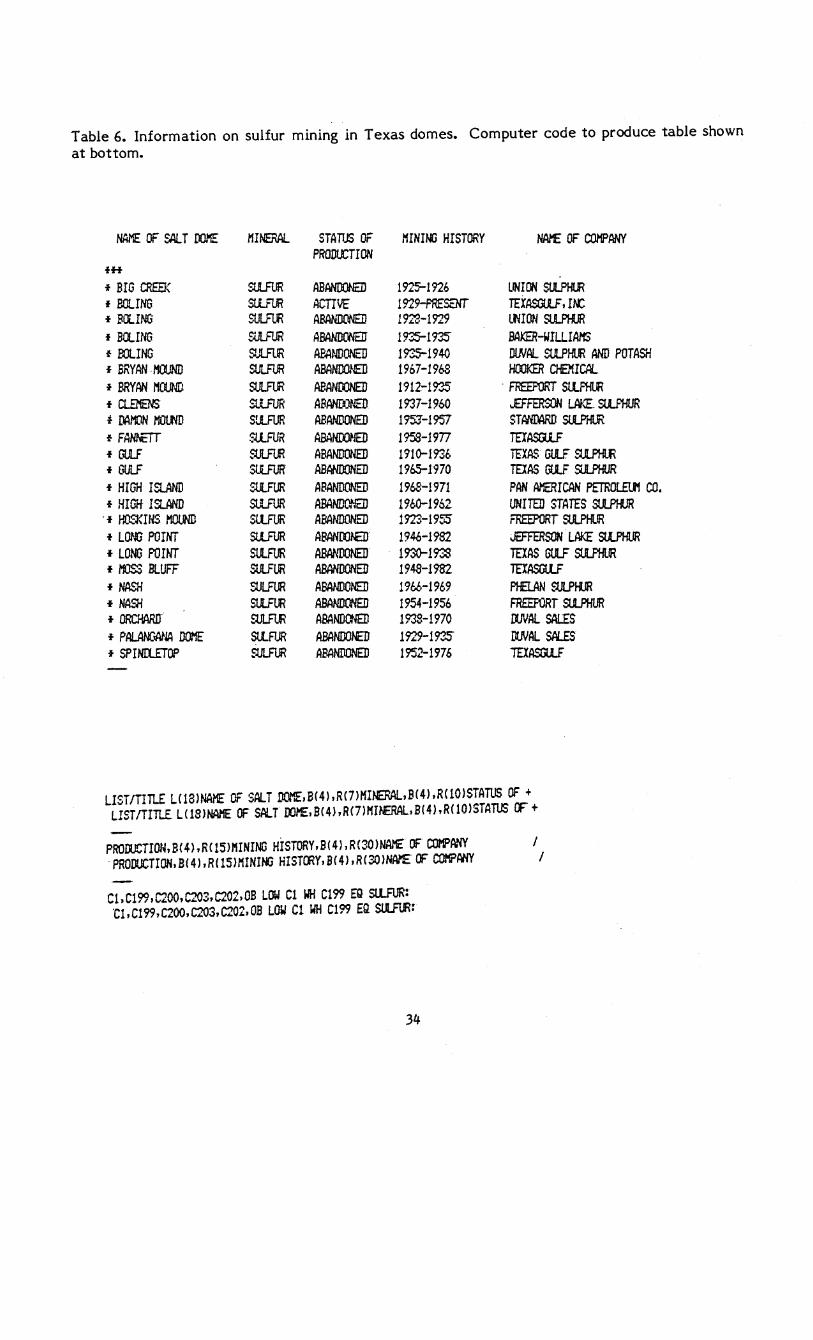
Table 6. Information on sulfur mining in Texas domes. Computer code to produce table shown at bottom.
NAME OF SALT mIllE MINERAL STAM OF I'IINIr.lJ HISTORY HArE OF COMPANY PRODUCTION
fH
* BIG CREEK SULFUR ABANDONED 192~1n6 UNION SUlPHlR f BOLING SLtrlJ1 ACTIVE 1929-PRESENr TEXASGLlF, IN: I FctING SUI..FtJl ABANDONED 1923-1929 LtiION Sl.lP!-lIR f aCtING SiJLF1.JR ABANDCWErr 1935-11',s BAt-EHHLLIAl1S f BOLING ~JlFlIR ABA~./DONED 19".:.5-1940 DIN~ SUlPHlIR AND POTASH f BRYAN·MOUND ~ ABANDOnED 1967-1968 HOOKER CHEXICAL f BRYAN I1ctlND SlIL.Frn ABANOONED 1912:-1935" . FREEPORT St.l.F'Hl.IR f CLEl9tS SLtFUR ABANDONED 1937-1960 ..EFFERSON LN~. SllF'HUR f DAMON MDltlD S'..lFlJR ABANDONED 19SJ-1957 STmrAAD SLlP'rilR f FANttIT ~.tlFUR ABAtmJED 1958-1977 TErAStUF I GULF rut.FLR ABANDONED 1910-1936 TEXASGULF~
16ULF SllFUR ABAI'IDONED 1965-1970 TErAS G!.lF ~ I HIGH ISLAND SUlFUR ABANDONED 1968-1971 PAN AMERICAN PETRDlEU'f CO. I HIGit ISlAND St1.FUR ABANDONED 1960-1962 UNITED STATES SUl..PIU
. I rro~~m1s MOUND SllFUR ABANDONED 1923-195S FREEPORT ru..PHlR I l~~ POINT SLtFUR ABANOOra 1946-1982 JEFFERSON LAKE StUHUR f Lo.~ romT SllFUR ABANDONED 1930-1938 TErAS GULF SU .. PHlIR I /'ftJSS BLUFF SUlFUR ABANDONED 1948-1982 TErASGtlF I NA.-"H SULFUR ABANDONED 19M-1969 MLAN SUI..PIiJR I NASH SllFLIR ABANDCWED 1954-1956 FREEF1JRT alPHUR I 0RCHAA.rr ~ ABANDCl-lEI) 1938-1970 roWll SALES f PAl..ANCWlA DOME SllFUR ABANDO~ 1929-193J DlNAl SIUS I SPINIliTOP SlIL.Frn ABANDONED 1952-1976 IDASru..F
LIeT/TITLE L(18INAME OF S~T DOME,B(4I,R(7)I1INERAL,B(41.R(10ISTATUS OF + LISTITITLE L(lSINAI'IE OF SALT DOME,B(4).RC7)MI~~.B(41,R(10ISTATUS OF+
PRODUCTION,B(41,R(151I1INING HiSTORY.B(41.R(30IN~ OF COMP~~ / ·PRODUCTIDN.B(41.R(151I'lINING HISTORY,B(4I,R(3QINAnEOF COMPANY /
C1,Cl99,C200.C203.C202,OB LOW C1 WH Cl99 EQ su..FUR: ·C1.Cl99.C200,C203.C202.0B LOW C1 WH C199 EQ SlUtR:
34

FIGURE CAPTIONS
1. Definition of diapir shape in plan view. (A) Major axis, minor axis, and major-axis
azimuth. (B) Crestal area and percentage planar Area is measured by planimetry. (C)
Three classes of diapir shape defined by different axial ratios.
2. Parameters describing inclined diapirs in three dimensions. These are calculated from
structure-contour maps on salt.
3. Parameters describing diapir overhang. Plan view (A) defines overhang and azimuth of
maximum overhang on a structure-contour map of the salt. Plan view (B) defines partial
overhang. Contours are elevation below sea level. Oblique view defines overhang area,
neck ara, overhang distance, and percentage overhang.
planimeter.
Areas are measured by
4. Qualitative classification of drainage systems above domes into five deal types as a guide
to relative movement of the land surface above.