Embed Size (px)
Citation preview

Computers & Fluids xxx (2009) xxx–xxx
ARTICLE IN PRESS
Contents lists available at ScienceDirect
Computers & Fluids
journal homepage: www.elsevier .com/ locate /compfluid
Flight force production by flapping insect wings in inclined stroke plane kinematics
Y. Sudhakar, S. Vengadesan *
Department of Applied Mechanics, IIT Madras, Chennai 600 036, India
a r t i c l e i n f o
Article history:Received 8 May 2009Received in revised form 13 November 2009Accepted 13 November 2009Available online xxxx
Keywords:Insect flightInclined stroke plane hoveringImmersed boundary methodWake captureFlapping wings
0045-7930/$ - see front matter � 2009 Elsevier Ltd. Adoi:10.1016/j.compfluid.2009.11.004
* Corresponding author. Tel.: +91 44 2257 4063; faE-mail address: [email protected] (S. Vengadesa
Please cite this article in press as: Sudhakar Y, VFluids (2009), doi:10.1016/j.compfluid.2009.11.
a b s t r a c t
The unsteady flow structure and the time-varying aerodynamic forces acting on a 2D dragonfly modelwing are studied by numerically solving the Navier–Stokes equations. The incompressible Navier–Stokesequations are discretized and solved on a non-body confirming Cartesian grid; the concept of immersedboundary method is made use of to impose the no-slip boundary condition on the surface of the wing.The objective of the present study is to investigate the influence of the following kinematic parameterson the flight performance of inclined stroke plane hovering: Reynolds number (Re), stroke amplitude,wing rotational timing and rotational duration. While the effects of the above mentioned parameterson the stroke averaged force coefficients are the same in both horizontal and inclined stroke planemotions, the spatiotemporal dynamics of vorticity which produce the effects are entirely different. Ourresults also indicate that the drag mechanism proposed for tiny insects does not seem to augment thevertical force generation in inclined stroke plane motion.
� 2009 Elsevier Ltd. All rights reserved.
1. Introduction
Conventional aerodynamic theories, owing to the intrinsicassumptions of quasi-steady flow incorporated in them, are inade-quate to explain the superior aerodynamic performance of insectwings [1]. Flapping wings produce substantially higher aerody-namic forces than those predicted by quasi-steady theories. Thefailure of such theories, in turn, propelled the research in exploringthe unsteady aerodynamic mechanisms employed by insects. Re-cent flow visualization studies on tethered and free-flying real in-sects [2–6], experiments performed using dynamically scaled-upmodels of flapping insect wings [7–13] and numerical simulationsof idealized wing motions [14–20] have successfully revealed andprovided deeper insights into some of the possible mechanismsused by insects during hovering and in some maneuvering flight.
Smoke flow visualizations over a tethered hawkmoth, Manducasexta and its similarity preserved flapping mechanical model iden-tified an intense attached Leading Edge Vortex (LEV), of sufficientstrength to explain the high-lift forces [3]. LEV enhanced the circu-lation and hence the lift generation around the flapping wings. Ithas been shown that the attached vortex was a result of dynamicstall, not of rotational mechanisms. The stability of LEV is mani-fested by different mechanisms at different Reynolds numbers(Re): at high Re (�5000) hawkmoth wings, a strong spanwise flowwas observed, which transported the excess vorticity out of LEV[3]; at low Re (=160) fluitfly wings, it has been hypothesized thatthe downwash induced by the tip vortex and the wake vorticity
ll rights reserved.
x: +91 44 2257 4050.n).
engadesan S. Flight force produ004
reduced the effective angle of attack (AOA) of wings and controlledthe growth of vorticity [8].
At the end of both half strokes, insects rotate their wings morerapidly, in preparation for the next half stroke. Dynamically scaledexperiments on the model fruitfly wings demonstrated the aerody-namic benefits of wing rotation [7]. Rapid rotation of wings duringstroke reversal acted as a source of additional circulation and en-hanced the aerodynamic forces produced. The authors assessedthat this mechanism was similar to Magnus effect, and was termedas rotational circulation. The wings of insects extracted energyfrom its own wake if the interacting AOA is properly adopted.Wake shed from the previous stroke acted to enhance the effectivefluid velocity encountered by insect wings. This favorable interac-tion of wing with the wake was named wake capture. In additionto the forces required to perform hovering, these rotational mech-anisms, rotational circulation and wake capture, can explain thealteration of aerodynamic forces on insect wings by which insectsperform aerial steering maneuvers. These three mechanisms, de-layed stall, rotational circulation and wake capture, can collectivelyaccount for most of the lift generation by flapping insect wings.
In order to understand how modifications in wing kinematicsalter the aerodynamic forces generated by a moving wing andhence to understand how insects precisely alter the kinematicsfor different aerial maneuvers, Sane and Dickinson [9] studied191 separate sets of kinematic patterns. Influences of the followingbehaviorally important kinematic parameters were studied: strokeamplitude, AOA, flip timing, flip duration, and the shape and mag-nitude of stroke deviation. The stroke velocity was varied as a trap-ezoidal function of time, which was the kinematics obtained fromtethered fruitfly. Recently, Wu and Sun [17] computed the aerody-
ction by flapping insect wings in inclined stroke plane kinematics. Comput
2 Y. Sudhakar, S. Vengadesan / Computers & Fluids xxx (2009) xxx–xxx
ARTICLE IN PRESS
namic forces generated by a model fruitfly wing, in which transla-tional velocity was varied as a simple harmonic function. The studyfocused on the influence of Re, mid-stroke plane AOA, stroke ampli-tude, non-dimensional duration of wing rotation and rotationaltiming. Time history of CL and CD published in these two studies[9,17] were completely different, owing to the difference in wingkinematics. A numerical study [21] was conducted to assess theinfluence of different wing kinematic models on the aerodynamicperformance of hovering fruitfly, which uses horizontal strokeplane motion.
Although, there have been number of experimental and compu-tational studies investigating lift generation in horizontal planeflapping (insects like fruitfly, honeybee), very few have consideredthose insects (like dragonfly, hoverfly) which use wing motionalong an inclined stroke plane [6,15,19,20]. The focus of the pres-ent work is to investigate how modifications in wing stroke kine-matics alter the aerodynamic force production in inclined strokeplane flapping.
Usherwood and Ellington [10] found that on the wings of vari-ous insects and a bird, an attached LEV was formed, and it was ofsufficient strength to generate enough lift force to balance theirweights. The dynamic stall mechanism can be operative in the Rerange from 140 (fruitfly) to 15,000 (quail). Very recently conductedexperiments [22] on active unrestricted slow-flying bats at Re of5000 demonstrated that the unsteady aerodynamic mechanismsin flapping flight are not restricted to insects alone, but are usedby large and heavier flying animals as well. However, CFD studiesof model 2D [23] and 3D [17] wings at low Re (<100) indicated thatthe LEV was very weak and much diffused at such low Re regimeand the dynamic stall mechanism may not be sufficient to explainthe flight of tiny insects; also the TEV was attached to the wing,which increased the negative circulation around the wing and low-ered the lift. When Re was reduced below 100, model wings pro-duced insufficient lift force to balance the insect weight andsubstantial amount of drag force [17,23]. It had been shown thatit was the drag force, which supports about 3/4th of the weightof dragonfly, which flaps its wings along an inclined stroke plane[19]. It is of interest to investigate whether the large drag foundin horizontal plane motions at low Re can act in inclined strokeplane motions and explain the flight of small insects. Though,Wang [15] reported that net vertical force was more than halvedwhen Re was reduced from 157 to 15.7, the physical basis of thisforce attenuation was not discussed in detail.
Forces produced on a model fruitfly wings changed drastically,when the timing of wing rotation was changed slightly [2,7,9,17].The sensitivity of force production and the corresponding fluiddynamical changes to the wing rotational timing are not discussedin detail for inclined stroke plane motions. In addition, it is ofinterest to examine the effects of wing rotation speed and strokeamplitude, as these kinematic parameters can largely influencethe flight force production [9,17]. In the present study, we inves-tigate the flight performance of insects, which employ wing flap-ping motion along an inclined stroke plane. The consequences ofvarying the following important kinematic parameters, through2D numerical simulations, are examined in detail to understandthe fluid dynamics of inclined stroke plane motions: Reynoldsnumber (Re), stroke amplitude (A0), rotational timing and rota-tional duration (Dsr).
Although, it has been found that spanwise flow is important instabilizing the vortex in high Re (�5000) hawkmoth hovering[3,14], studies on fruitfly flapping observed no evidence of span-wise flow [8] at low Re (�110) flow. Since the maximum Re consid-ered in our simulations is 150, 2D study can be appropriate incapturing the LEV. Despite the difference in the LEV structures,the agreement between 3D dragonfly wings and 2D computationwas quite good [18]. In a recent study [24], 2D numerical simula-
Please cite this article in press as: Sudhakar Y, Vengadesan S. Flight force produFluids (2009), doi:10.1016/j.compfluid.2009.11.004
tions were compared against 3D robotic wing experiments. It leadto the following conclusions: firstly, simulation captured majorfeatures of vortex dynamics throughout the stroke cycle; secondly,computed drag matched well with experiments in all cases, liftagreed with experiments in advanced and symmetric rotationcases. In conclusion, 2D numerical simulations were very goodapproximations for 3D experiments.
2. Wing kinematics
Free flight wing kinematics measurements of many insects[25,26] obtained using high speed video indicated that the wingtranslational velocity varies approximately as a Simple HarmonicFunction (SHF). However, the insects were filmed with only onecamera, so the measurements cannot be considered as accurate.Recently, the time course of three-dimensional (3D) wing motionsof freely flying fruitflies [12], honeybees [13] and droneflies [27]were measured using three orthogonally aligned high-speed cam-eras. All these studies confirm the variation of translational veloc-ity as SHF and the wing rotation was confined to stroke reversal.Recent tethered flight kinematic measurements of dragonfly [20]confirmed the same prediction for inclined stroke plane kinematicsalso. The mathematical approximations to the considered wingkinematics are as follows:
Translational velocity,
vðsÞ ¼ � sin 2c
A0s
� �ð1Þ
Angular velocity confined to stroke reversal,
xðsÞ ¼ x 1� cos2pðs� srÞ
Dsr
� �� �; sr 6 s 6 sr þ Dsr ð2Þ
where s is the non-dimensional time, c is the chord length of thewing, A0 is the stroke amplitude, sr is the time at which the rotationstarts, Dsr is the time required to perform the rotation, x ¼ Dh
Dsris the
average rotational speed and Dh is the change in AOA achieved inwing rotation.
Non-dimensional period of wing beat cycle (sc) can be found bythe following relation,
2c
A0sc ¼ 2p ð3Þ
3. Numerical methodology: immersed boundary method
Understanding the fluid dynamics of flapping locomotionnecessitates the simulation of flow over complex moving bound-aries. The requirement of generation of a high quality mesh in con-ventional CFD methods makes it very difficult to handle complexgeometries. While simulating the flow past moving boundaries,transient re-meshing strategies need to be incorporated to accountfor the change of shape or orientation of the body in the fluid flow.In addition to increase in the computational cost, the accuracy andconvergence properties of the conventional methods are primarilyaffected by quality of the grid.
In order to circumvent the problems associated with conven-tional CFD methods to handle complex moving boundaries, thegoverning equations are discretized and solved on a Cartesianmesh. The concept of Immersed Boundary Method (IBM) is madeuse of to impose the no-slip boundary condition: singular forcesof appropriate magnitude and direction are applied at the solid–fluid interface in such a way that, this would result in the enforce-ment of required boundary conditions. These forces are then,distributed on the Cartesian grid points to bring-in the influenceof presence of the body into the flow field.
ction by flapping insect wings in inclined stroke plane kinematics. Comput

Y. Sudhakar, S. Vengadesan / Comput
ARTICLE IN PRESS
Owing to the simplicity with which IBM handles the complexmoving boundaries, it has gained the attention of CFD researchersin recent years. Many researchers have used IBM to understand thefish hydrodynamics [28–31] and insect aerodynamics [23,32–34].Even very complicated Large Eddy Simulation (LES) of turbulencealso has been carried out in the immersed boundary methodframework [35–38].
Among many variants of existing IBMs, we chose to use the ideaof implicit force calculation [39]. Implicit calculation of Lagrangianforces eliminates the time step restriction imposed upon the com-putation. We make two essential changes: first, time integration ofthe Navier–Stokes equations have been carried out by means of asecond order projection method [40], which provides second orderconvergence for pressure; second, we make use of the four-pointregularized delta function [41], which posses much wider stabilityregion and results in efficient enforcement of boundary conditionsthan any other delta functions.
The algorithm for one time step is explained as follows:
1. Solve momentum equations without considering the presenceof immersed boundaries and obtain intermediate velocity com-ponent u*(x). On the domain boundaries, the required boundaryconditions for the problem considered are applied.
u� � un
Dt¼ �3
2rhðuuÞn þ 1
2rhðuuÞn�1 �rhpn þ 1
2Rer2
hðu� þ unÞ ð4Þ
The convective and diffusive terms are discretized using Adams–Bashforth and Crank–Nicolson schemes respectively, which provideoverall second order accuracy.
2. Obtain the velocity components on the Lagrangian points U*(Xk)by interpolating nearby Eulerian points’ velocities u*(x)
U�ðXkÞ ¼X
x
u�ðxÞdhðx� XkÞh2 ð5Þ
3. Calculate the Lagrangian forces F*(Xk) from prescribed boundaryvelocities Un+1(Xk) and interpolated velocities at Lagrangianpoints U*(Xk)
XM
j¼1
Xx
dhðx� XjÞdhðx� XkÞDsh2
" #F�ðXjÞ ¼
Unþ1ðXkÞ � U�ðXkÞDt
ð6Þ
4. Distribute Lagrangian forces F*(Xk) to the nearby Eulerian pointsf*(x)
f �ðxÞ ¼XM
k¼1
F�ðXkÞdhðx� XkÞDs ð7Þ
where Ds is the distance between adjacent Lagrangian points
5. Correct the intermediate velocity u**(x) using the Eulerian forcesf*(x) and obtain another intermediate velocity u(x)
u�� � u�
Dt¼ f � ð8Þ
6. Solve a Poisson equation for pressure correction
r2hp0 ¼ rh � u��
Dtð9Þ
The algebraic system of equations resulting from discretization ofPoisson equation is solved using BiCGSTAB(2) algorithm [42].
Please cite this article in press as: Sudhakar Y, Vengadesan S. Flight force produFluids (2009), doi:10.1016/j.compfluid.2009.11.004
7. Correct pressure and velocities
pnþ1 ¼ pn þ p0 � 12Rerh � u�� ð10Þ
unþ1 � u��
Dt¼ �rhp0 ð11Þ
For spatial differencing of momentum equations, second ordercentral differencing is used for viscous terms. Since the upwindschemes exhibit excessive artificial diffusion characteristics, con-vective terms in conservative form are discretized using second or-der central differencing. First order Euler integration has beenapplied for time stepping.
In the above formulations, d is the Dirac delta function which isemployed to transfer the quantities between Eulerian and Lagrang-ian domains effectively. The two dimensional discrete version ofdelta function is,
dhðxÞ ¼1
h2 /ðxÞ/ðyÞ ð12Þ
where, h is the Eulerian mesh width, x and y are the Cartesian com-ponents. u is the hat function, which can be formulated in manyways depending upon the number of nearby points it uses. In oursolver, we use four-point delta function which ensures more accu-rate boundary condition imposition [41].
/ðrÞ ¼
18 ð3� 2jrj þ
ffiffiffiffiffiffiffiffiffiffiffiffiffiffiffiffiffiffiffiffiffiffiffiffiffiffiffiffiffi1þ 4jrj � 4r2
pÞ if 0 6 jrj 6 1
18 ð5� 2jrj þ
ffiffiffiffiffiffiffiffiffiffiffiffiffiffiffiffiffiffiffiffiffiffiffiffiffiffiffiffiffiffiffiffiffiffiffiffi�7þ 12jrj � 4r2
pÞ if 1 6 jrj 6 2
0 otherwise
8>>>><>>>>:
ð13Þ
The use of delta function smears the location of boundary toseveral grid cells, and results in the velocity field which is seem-ingly smoother. Though seemingly smoother, the velocity fieldobtained from Eq. (8) contains discontinuity in velocity gradientacross the immersed boundary. One might expect the presenceof such discontinuity results in divergence of the solution. Analy-sis of one-dimensional model for the immersed boundary has re-vealed that the order of accuracy is reduced to first-order nearthe boundaries due to the presence of such discontinuity [43].Mori [44] has proved the convergence of IBM solution by analyz-ing steady Navier–Stokes equation in Stokes flow regime. In arecent article [45], the authors have derived the sufficient condi-tions under which the projection method converges when usedwith immersed boundary methods. They showed that if thevelocity field produced after Eq. (8) is close to the divergence-freefield, then the solution converges to the original solution. By ana-lyzing time-dependent incompressible Navier–Stokes equations,the authors concluded that since the projection method is used,the velocity field produced after Eq. (8) is not arbitrary, but isvery close to the divergence-free field. Hence, when immersedboundary forcing methods are used with projection methods,the convergence is guaranteed. Although the scheme convergedas the mesh spacing goes to zero, the order of accuracy is reducedby the lack of smoothness, which is consistent with [43,44].
Aerodynamic forces acting over the immersed boundaries canbe evaluated by integrating the Lagrangian forces over the lengthof the interface, or by integrating the Eulerian forces over thewhole fluid domain.
FV ¼ �Z
Xfydxdy ¼ �
Z L
0Fyds ð14Þ
FH ¼ �Z
Xfxdxdy ¼ �
Z L
0Fxds ð15Þ
ers & Fluids xxx (2009) xxx–xxx 3
ction by flapping insect wings in inclined stroke plane kinematics. Comput

Fig. 1. Validation study for horizontal stroke plane motion (a) CL comparison (b) CD
comparison.
4 Y. Sudhakar, S. Vengadesan / Computers & Fluids xxx (2009) xxx–xxx
ARTICLE IN PRESS
where FV and FH are respectively the vertical and horizontal compo-nents of the total aerodynamic force. L is the length of the interfaceand X is the domain which contains the interface. In our study, theforces are non-dimensionalized with RMS velocity of flapping andchord length of the wing.
4. Validation studies
The solver was validated against the standard test cases: flowpast (1) stationary circular cylinder, (2) rotating circular cylinder,(3) translationally oscillating cylinder in free-stream flow and (4)inline oscillating cylinder in still fluid. Our results are in goodagreement with those reported in the literature [46]. Having dem-onstrated the ability of our Navier–Stokes solver to handle station-ary and moving circular cylinders, the next step is to checkwhether the implemented numerical methodology can be usedto simulate the flow around flapping insect wing kinematics. Twostudies have been carried out for such validation. In the first one,the wing moves along a horizontal stroke plane and in the second,the translation of wing is along an inclined stroke plane.
4.1. Fruitfly kinematics
A flat plate with thickness ratio of 2% is used to model the cross-section of the wing. The kinematics of the model wing is similar tothat used by Miller and Peskin [23] and is a simplification of flightin fruitfly. Only first flapping cycle is considered. Downstroke, up-stroke and supination are included in the wing motion; pronationis not considered. Each half stroke (downstroke and upstroke) is di-vided into three stages: translational acceleration at the beginning,constant velocity translation and translational deceleration at theend of half stroke. The wing rotates about a point which is locatedat 0.2 chord lengths from the leading edge. The parameters of thesimulations are: Re ¼ vmaxc
t
� �¼ 128 and A0/c = 5.
The trajectory of force coefficients for the complete stroke isshown in Fig. 1. It can be inferred that the results obtained fromour solver closely matches with the literature results [23]; bothCL and CD agree very well with the time history of reported results.During acceleration and wing rotation phases, our results under-predicted the force peaks observed. However, the trend is pre-dicted accurately.
4.2. Dragonfly kinematics
The kinematics is the same as that used by Wang [15]. An el-lipse of thickness ratio 0.25 is used to model the wing cross section.The parameters of the simulation are: Re = 157, A0/c = 2.5, b = 45�.The time course of CV and CH (the nomenclature is explained inFig. 8) for one complete stroke is shown in Fig. 2. It can be seen thatCH matches exactly with the other reported studies. The forcepeaks in CV are over-predicted by our solver; however, othernumerical studies also differ significantly in this regime. The smalldifferences observed in the CV peaks can be attributed to the differ-ences in the way in which the governing equations are discretizedand solved.
5. Grid details and boundary conditions
A flat plate of 2% thickness to chord ratio is used to model thewing cross-section. The plate is discretized with 102 Lagrangianpoints (Ds = 0.02). The size of the rectangular computational do-main chosen is (�30c 6 x 6 30c, �30c 6 y 6 30c). A small areawithin the computational domain is discretized with uniform grid,Dx = Dy = 0.02. The size of the area is chosen in such a way that thewing is immersed within the uniform grid region throughout the
Please cite this article in press as: Sudhakar Y, Vengadesan S. Flight force produFluids (2009), doi:10.1016/j.compfluid.2009.11.004
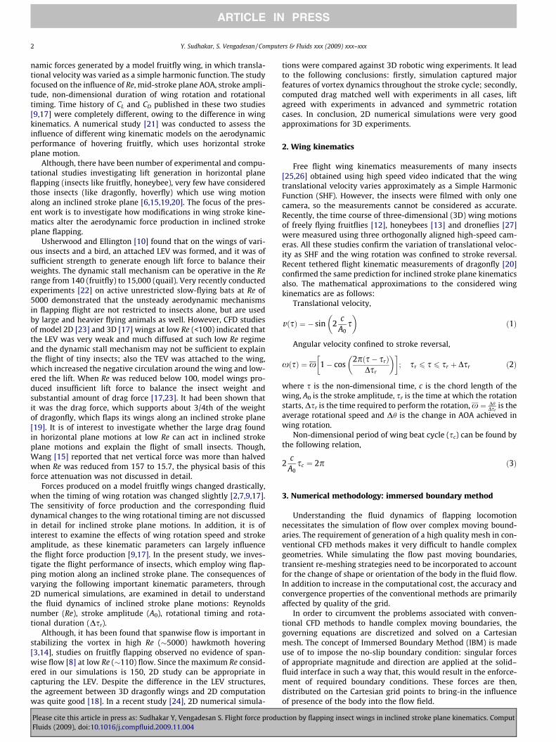
stroke. A picture of wing immersed in the non-body conformalCartesian grid is shown in Fig. 3. When A0/c = 2.5, the size of theuniform grid area is (�1.9c 6 x 6 0.6c, �2.8c 6 y 6 0.6c) and is in-creased when A0/c increases. In the remaining area of the compu-tational domain, a non-uniform stretched grid is used. The size ofthe Eulerian grid in x- and y-direction is 397 and 438 respectivelyfor 2.5 chord lengths travel.
Since our study is concerned with hovering insects, the wing ismoving in still air with the absence of free-stream velocity. Onthe left and right boundaries of the computational domain, Neu-mann boundary condition for velocities @u
@x ¼ @v@x ¼ 0
� �is applied.
On the top and bottom boundaries, symmetry boundary condition@u@y ¼ v ¼ 0
is applied. These are schematically shown in Fig. 4.Every flapping cycle is discretized with 2000 time steps(Ds = sc/2000).
5.1. Domain independent study
The sensitivity of the computational domain size on the numer-ical computations is evaluated for the Re = 150 case. The computa-tional domain chosen in our study are domain-1: (�30c 6 x 6 30c,�30c 6 y 6 30c) and domain-2: (�60c 6 x 6 60c, �60c 6 y 660c). It should be noted that the domain-2 is two times that of do-main-1 in both the directions. In both these domains, the flat plateis represented with 102 Lagrangian points. A small area within thecomputational domain (�1.9c 6 x 6 0.6c, �2.8c 6 y 6 0.6c) is dis-cretized with uniform grid, having Dx = Dy = 0.02. The stretching
ction by flapping insect wings in inclined stroke plane kinematics. Comput
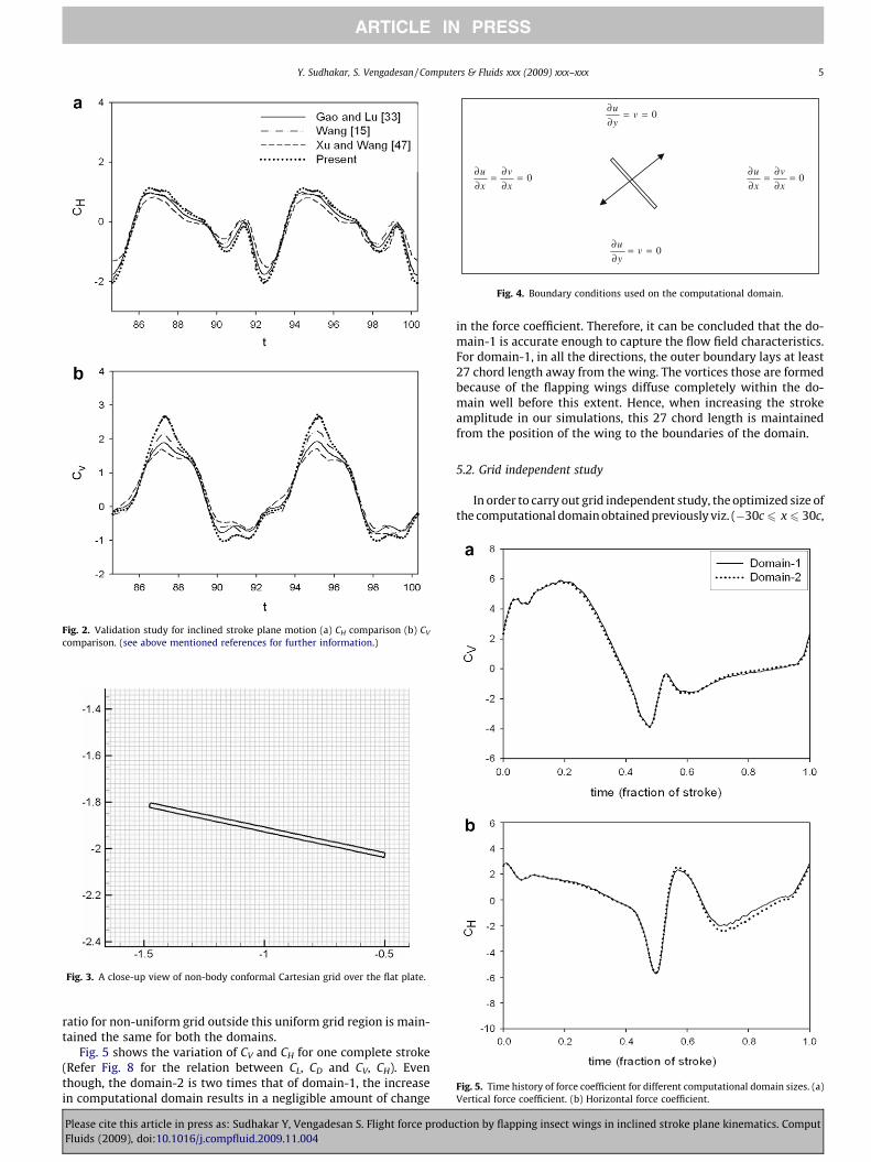
Fig. 2. Validation study for inclined stroke plane motion (a) CH comparison (b) CV
comparison. (see above mentioned references for further information.)
Fig. 3. A close-up view of non-body conformal Cartesian grid over the flat plate.
Fig. 4. Boundary conditions used on the computational domain.
Fig. 5. Time history of force coefficient for different computational domain sizes. (a)Vertical force coefficient. (b) Horizontal force coefficient.
Y. Sudhakar, S. Vengadesan / Computers & Fluids xxx (2009) xxx–xxx 5
ARTICLE IN PRESS
ratio for non-uniform grid outside this uniform grid region is main-tained the same for both the domains.
Fig. 5 shows the variation of CV and CH for one complete stroke(Refer Fig. 8 for the relation between CL, CD and CV, CH). Eventhough, the domain-2 is two times that of domain-1, the increasein computational domain results in a negligible amount of change
Please cite this article in press as: Sudhakar Y, Vengadesan S. Flight force produFluids (2009), doi:10.1016/j.compfluid.2009.11.004
in the force coefficient. Therefore, it can be concluded that the do-main-1 is accurate enough to capture the flow field characteristics.For domain-1, in all the directions, the outer boundary lays at least27 chord length away from the wing. The vortices those are formedbecause of the flapping wings diffuse completely within the do-main well before this extent. Hence, when increasing the strokeamplitude in our simulations, this 27 chord length is maintainedfrom the position of the wing to the boundaries of the domain.
5.2. Grid independent study
In order to carry out grid independent study, the optimized size ofthe computational domain obtained previously viz. (�30c 6 x 6 30c,
ction by flapping insect wings in inclined stroke plane kinematics. Comput
6 Y. Sudhakar, S. Vengadesan / Computers & Fluids xxx (2009) xxx–xxx
ARTICLE IN PRESS
�30c 6 y 6 30c) is considered. The size of the uniform grid region is(�1.9c 6 x 6 0.6c, �2.8c 6 y 6 0.6c). In grid-1, the flat plate isdiscretized with 102 Lagrangian points. The uniform grid region isdiscretized with Dx = Dy = 0.02, resulting in the Eulerian grid sizeof 397 and 438 points respectively in x- and y-directions. In grid-2,the flat plate is discretized with 204 Lagrangian points. The uniformgrid region is discretized with Dx = Dy = 0.01, resulting in the Euleri-an grid size of 605 and 686 points respectively in x- and y-directions.The stretching ratio outside the domain is same for both the grids.Hence, changing the uniform grid region automatically changes thegrid size outside the uniform domain accordingly.
The time course of CV and CH for one complete stroke for dif-ferent grids is shown in Fig. 6. Though, the number of Lagrangianpoints and the number of Eulerian grid points within the uniformgrid domain is doubled, the resulting variation in force coeffi-cients is not highly significant. During upstroke, there is a smallvariation in computed CH for different grids. However, the timehistory of CV almost coincides for both the grids considered –the variation is negligible. The stroke averaged vertical force coef-ficient, CH is near zero in our simulations, which confirms thatthe present kinematics with the chosen variables represent insecthovering. Only the variation of vertical force coefficient CV andthe corresponding fluid dynamics of inclined stroke plane hover-ing is studied in the following sections. Hence, grid-1, 102Lagrangian points and Dx = Dy = 0.02 in the uniform grid Euleriandomain, is considered accurate for all the simulations in thepaper.
Fig. 6. Time history of force coefficient for different computational grid. (a) Verticalforce coefficient. (b) Horizontal force coefficient.
Please cite this article in press as: Sudhakar Y, Vengadesan S. Flight force produFluids (2009), doi:10.1016/j.compfluid.2009.11.004
5.3. Time-step independent study
The optimized computational domain and grid are used to carryout time-step independent study. The time-step sizes are deter-mined by the number of iterations performed for one flapping cy-cle. In simulation-1, 2000 iterations are performed for one cycle(Dsr = sc/2000), and in simulation-2, 4000 iterations are performed(Dsr = sc/4000). When the amplitude of wing translation is 2.5times of its chord length, the time-step sizes are Dsr = 0.00125pand Dsr = 0.000625p respectively in simulation-1 and -2. The timecourse of CV and CH for one complete stroke is shown in Fig. 7.Though the time step size in simulation-2 is half times that ofthe simulation-1, the resulting variation in the time course of forcecoefficients is not very significant. Hence (Dsr = sc/2000) is used inall our simulations.
The grid and time-step independent studies confirm that thenumerical simulations we have performed with our solver are inthe limit of discretization step in space and time going to zero.
6. Results and discussion
All the results presented in the subsequent sections are for thewing during the 10th cycle of flapping, in which the forces and flowreached a periodic state. The relation between lift (CL), drag (CD)coefficients and horizontal (CH), vertical (CV) force coefficients areshown in Fig. 8. It can be seen that the components of both lift
Fig. 7. Time history of force coefficient for different computational time-step sizes.(a) Vertical force coefficient. (b) Horizontal force coefficient.
ction by flapping insect wings in inclined stroke plane kinematics. Comput
Y. Sudhakar, S. Vengadesan / Computers & Fluids xxx (2009) xxx–xxx 7
ARTICLE IN PRESS
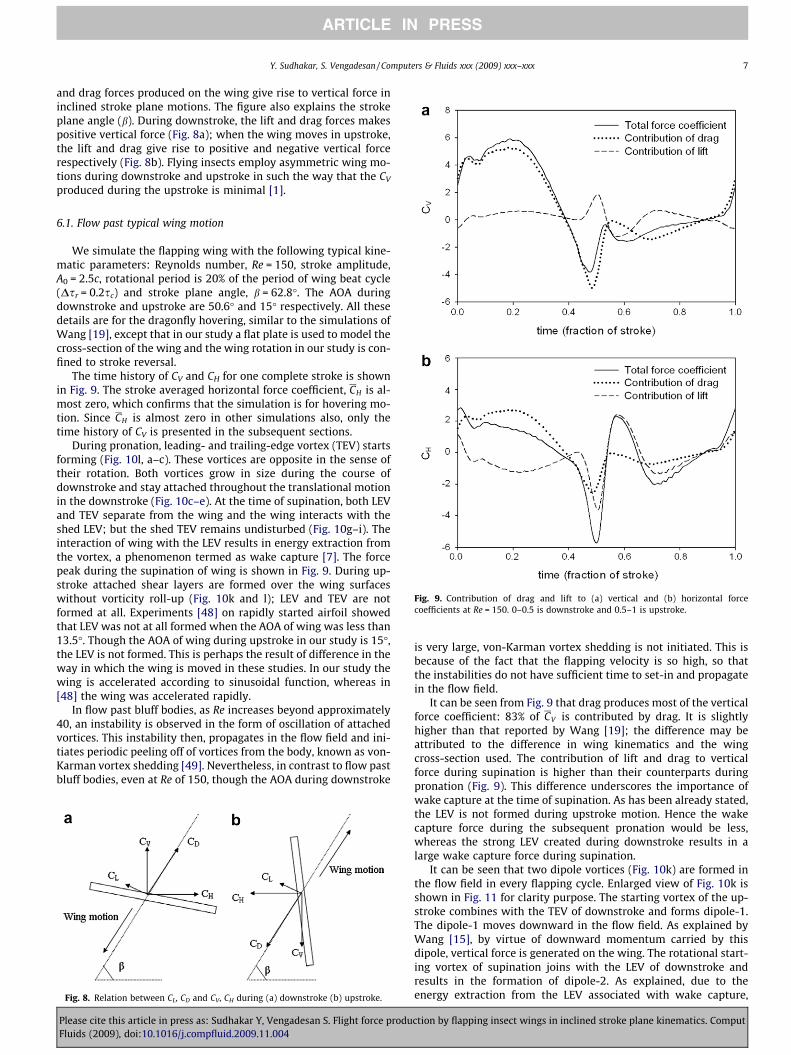
and drag forces produced on the wing give rise to vertical force ininclined stroke plane motions. The figure also explains the strokeplane angle (b). During downstroke, the lift and drag forces makespositive vertical force (Fig. 8a); when the wing moves in upstroke,the lift and drag give rise to positive and negative vertical forcerespectively (Fig. 8b). Flying insects employ asymmetric wing mo-tions during downstroke and upstroke in such the way that the CV
produced during the upstroke is minimal [1].
Fig. 9. Contribution of drag and lift to (a) vertical and (b) horizontal forcecoefficients at Re = 150. 0–0.5 is downstroke and 0.5–1 is upstroke.
6.1. Flow past typical wing motion
We simulate the flapping wing with the following typical kine-matic parameters: Reynolds number, Re = 150, stroke amplitude,A0 = 2.5c, rotational period is 20% of the period of wing beat cycle(Dsr = 0.2sc) and stroke plane angle, b = 62.8�. The AOA duringdownstroke and upstroke are 50.6� and 15� respectively. All thesedetails are for the dragonfly hovering, similar to the simulations ofWang [19], except that in our study a flat plate is used to model thecross-section of the wing and the wing rotation in our study is con-fined to stroke reversal.
The time history of CV and CH for one complete stroke is shownin Fig. 9. The stroke averaged horizontal force coefficient, CH is al-most zero, which confirms that the simulation is for hovering mo-tion. Since CH is almost zero in other simulations also, only thetime history of CV is presented in the subsequent sections.
During pronation, leading- and trailing-edge vortex (TEV) startsforming (Fig. 10l, a–c). These vortices are opposite in the sense oftheir rotation. Both vortices grow in size during the course ofdownstroke and stay attached throughout the translational motionin the downstroke (Fig. 10c–e). At the time of supination, both LEVand TEV separate from the wing and the wing interacts with theshed LEV; but the shed TEV remains undisturbed (Fig. 10g–i). Theinteraction of wing with the LEV results in energy extraction fromthe vortex, a phenomenon termed as wake capture [7]. The forcepeak during the supination of wing is shown in Fig. 9. During up-stroke attached shear layers are formed over the wing surfaceswithout vorticity roll-up (Fig. 10k and l); LEV and TEV are notformed at all. Experiments [48] on rapidly started airfoil showedthat LEV was not at all formed when the AOA of wing was less than13.5�. Though the AOA of wing during upstroke in our study is 15�,the LEV is not formed. This is perhaps the result of difference in theway in which the wing is moved in these studies. In our study thewing is accelerated according to sinusoidal function, whereas in[48] the wing was accelerated rapidly.
In flow past bluff bodies, as Re increases beyond approximately40, an instability is observed in the form of oscillation of attachedvortices. This instability then, propagates in the flow field and ini-tiates periodic peeling off of vortices from the body, known as von-Karman vortex shedding [49]. Nevertheless, in contrast to flow pastbluff bodies, even at Re of 150, though the AOA during downstroke
Fig. 8. Relation between CL, CD and CV, CH during (a) downstroke (b) upstroke.
Please cite this article in press as: Sudhakar Y, Vengadesan S. Flight force produFluids (2009), doi:10.1016/j.compfluid.2009.11.004
is very large, von-Karman vortex shedding is not initiated. This isbecause of the fact that the flapping velocity is so high, so thatthe instabilities do not have sufficient time to set-in and propagatein the flow field.
It can be seen from Fig. 9 that drag produces most of the verticalforce coefficient: 83% of CV is contributed by drag. It is slightlyhigher than that reported by Wang [19]; the difference may beattributed to the difference in wing kinematics and the wingcross-section used. The contribution of lift and drag to verticalforce during supination is higher than their counterparts duringpronation (Fig. 9). This difference underscores the importance ofwake capture at the time of supination. As has been already stated,the LEV is not formed during upstroke motion. Hence the wakecapture force during the subsequent pronation would be less,whereas the strong LEV created during downstroke results in alarge wake capture force during supination.
It can be seen that two dipole vortices (Fig. 10k) are formed inthe flow field in every flapping cycle. Enlarged view of Fig. 10k isshown in Fig. 11 for clarity purpose. The starting vortex of the up-stroke combines with the TEV of downstroke and forms dipole-1.The dipole-1 moves downward in the flow field. As explained byWang [15], by virtue of downward momentum carried by thisdipole, vertical force is generated on the wing. The rotational start-ing vortex of supination joins with the LEV of downstroke andresults in the formation of dipole-2. As explained, due to theenergy extraction from the LEV associated with wake capture,
ction by flapping insect wings in inclined stroke plane kinematics. Comput
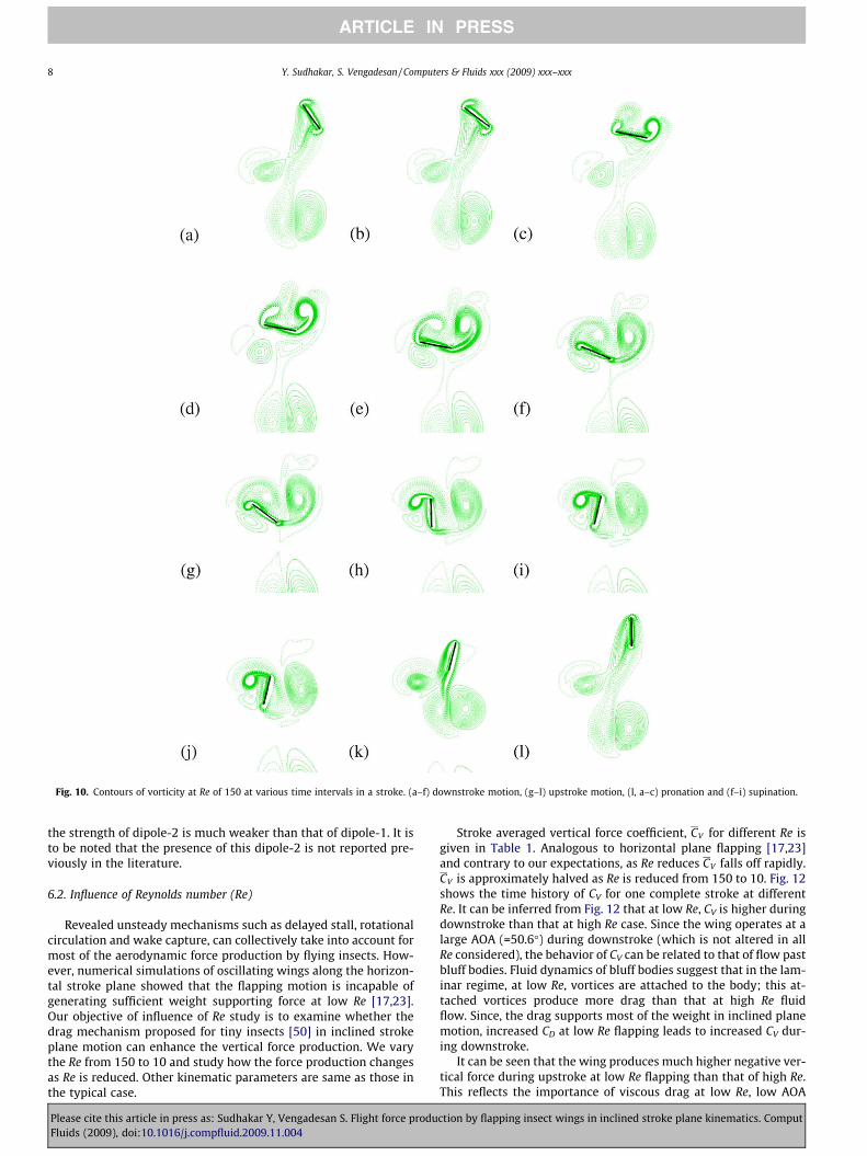
Fig. 10. Contours of vorticity at Re of 150 at various time intervals in a stroke. (a–f) downstroke motion, (g–l) upstroke motion, (l, a–c) pronation and (f–i) supination.
8 Y. Sudhakar, S. Vengadesan / Computers & Fluids xxx (2009) xxx–xxx
ARTICLE IN PRESS
the strength of dipole-2 is much weaker than that of dipole-1. It isto be noted that the presence of this dipole-2 is not reported pre-viously in the literature.
6.2. Influence of Reynolds number (Re)
Revealed unsteady mechanisms such as delayed stall, rotationalcirculation and wake capture, can collectively take into account formost of the aerodynamic force production by flying insects. How-ever, numerical simulations of oscillating wings along the horizon-tal stroke plane showed that the flapping motion is incapable ofgenerating sufficient weight supporting force at low Re [17,23].Our objective of influence of Re study is to examine whether thedrag mechanism proposed for tiny insects [50] in inclined strokeplane motion can enhance the vertical force production. We varythe Re from 150 to 10 and study how the force production changesas Re is reduced. Other kinematic parameters are same as those inthe typical case.
Please cite this article in press as: Sudhakar Y, Vengadesan S. Flight force produFluids (2009), doi:10.1016/j.compfluid.2009.11.004
Stroke averaged vertical force coefficient, CV for different Re isgiven in Table 1. Analogous to horizontal plane flapping [17,23]and contrary to our expectations, as Re reduces CV falls off rapidly.CV is approximately halved as Re is reduced from 150 to 10. Fig. 12shows the time history of CV for one complete stroke at differentRe. It can be inferred from Fig. 12 that at low Re, CV is higher duringdownstroke than that at high Re case. Since the wing operates at alarge AOA (=50.6�) during downstroke (which is not altered in allRe considered), the behavior of CV can be related to that of flow pastbluff bodies. Fluid dynamics of bluff bodies suggest that in the lam-inar regime, at low Re, vortices are attached to the body; this at-tached vortices produce more drag than that at high Re fluidflow. Since, the drag supports most of the weight in inclined planemotion, increased CD at low Re flapping leads to increased CV dur-ing downstroke.
It can be seen that the wing produces much higher negative ver-tical force during upstroke at low Re flapping than that of high Re.This reflects the importance of viscous drag at low Re, low AOA
ction by flapping insect wings in inclined stroke plane kinematics. Comput
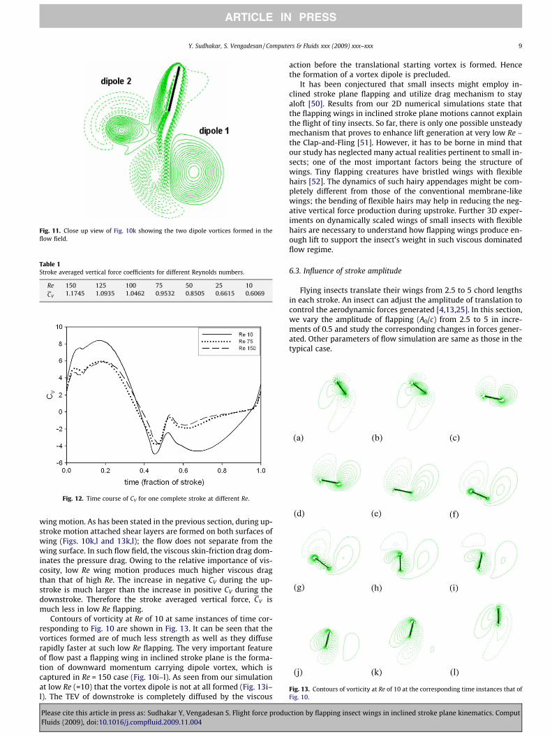
Fig. 11. Close up view of Fig. 10k showing the two dipole vortices formed in theflow field.
Table 1Stroke averaged vertical force coefficients for different Reynolds numbers.
Re 150 125 100 75 50 25 10CV 1.1745 1.0935 1.0462 0.9532 0.8505 0.6615 0.6069
Fig. 12. Time course of CV for one complete stroke at different Re.
Fig. 13. Contours of vorticity at Re of 10 at the corresponding time instances that ofFig. 10.
Y. Sudhakar, S. Vengadesan / Computers & Fluids xxx (2009) xxx–xxx 9
ARTICLE IN PRESS
wing motion. As has been stated in the previous section, during up-stroke motion attached shear layers are formed on both surfaces ofwing (Figs. 10k,l and 13k,l); the flow does not separate from thewing surface. In such flow field, the viscous skin-friction drag dom-inates the pressure drag. Owing to the relative importance of vis-cosity, low Re wing motion produces much higher viscous dragthan that of high Re. The increase in negative CV during the up-stroke is much larger than the increase in positive CV during thedownstroke. Therefore the stroke averaged vertical force, CV ismuch less in low Re flapping.
Contours of vorticity at Re of 10 at same instances of time cor-responding to Fig. 10 are shown in Fig. 13. It can be seen that thevortices formed are of much less strength as well as they diffuserapidly faster at such low Re flapping. The very important featureof flow past a flapping wing in inclined stroke plane is the forma-tion of downward momentum carrying dipole vortex, which iscaptured in Re = 150 case (Fig. 10i–l). As seen from our simulationat low Re (=10) that the vortex dipole is not at all formed (Fig. 13i–l). The TEV of downstroke is completely diffused by the viscous
Please cite this article in press as: Sudhakar Y, Vengadesan S. Flight force produFluids (2009), doi:10.1016/j.compfluid.2009.11.004
action before the translational starting vortex is formed. Hencethe formation of a vortex dipole is precluded.
It has been conjectured that small insects might employ in-clined stroke plane flapping and utilize drag mechanism to stayaloft [50]. Results from our 2D numerical simulations state thatthe flapping wings in inclined stroke plane motions cannot explainthe flight of tiny insects. So far, there is only one possible unsteadymechanism that proves to enhance lift generation at very low Re –the Clap-and-Fling [51]. However, it has to be borne in mind thatour study has neglected many actual realities pertinent to small in-sects; one of the most important factors being the structure ofwings. Tiny flapping creatures have bristled wings with flexiblehairs [52]. The dynamics of such hairy appendages might be com-pletely different from those of the conventional membrane-likewings; the bending of flexible hairs may help in reducing the neg-ative vertical force production during upstroke. Further 3D exper-iments on dynamically scaled wings of small insects with flexiblehairs are necessary to understand how flapping wings produce en-ough lift to support the insect’s weight in such viscous dominatedflow regime.
6.3. Influence of stroke amplitude
Flying insects translate their wings from 2.5 to 5 chord lengthsin each stroke. An insect can adjust the amplitude of translation tocontrol the aerodynamic forces generated [4,13,25]. In this section,we vary the amplitude of flapping (A0/c) from 2.5 to 5 in incre-ments of 0.5 and study the corresponding changes in forces gener-ated. Other parameters of flow simulation are same as those in thetypical case.
ction by flapping insect wings in inclined stroke plane kinematics. Comput

Fig. 15. Contours of vorticity at the beginning of downstroke for (a) A0 = 2.5c (b)A0 = 5c.
Table 2Stroke averaged vertical force coefficients for different stroke amplitudes.
A0/c 2.5 3 3.5 4 4.5 5CV 1.1745 1.1702 1.1718 1.0875 0.958 0.9309
10 Y. Sudhakar, S. Vengadesan / Computers & Fluids xxx (2009) xxx–xxx
ARTICLE IN PRESS
The total stroke duration (sc) increases as the amplitude oftranslation increases (Eq. (3)). In our simulations, Dsr/sc is main-tained as 0.2 for all A0 considered. Hence when A0 increases, Dsr
correspondingly increases. This implies that for shallow amplitudeflapping, the wing pronates and supinates at very high angularvelocity. As a consequence, in shallow amplitude flapping the rota-tional force peaks produced during pronation and supination arelarger than that of large amplitude flapping (Fig. 14).
Not only during the rotational phases, but also during the initialtranslational phase in the downstroke, the CV in shallow amplitudeflapping is larger (Fig. 14). This behavior results from two aerody-namic effects: firstly, since the wing flips rapidly faster in low A0
flapping, the resulting vortical structures produced are strongerthan that of large amplitude flapping (Fig. 15). When the wingtravels through this strong vorticity field, it produces a higherwake capture forces [7]. Secondly, as sc is small for shallow ampli-tude flapping, the wing accelerates faster during the initial phase ofthe downstroke and attains its maximum velocity in a short dura-tion. As a result, the added mass forces are higher in low A0 flap-ping. These two effects, wake capture and added mass, act incombination in low A0 motions to produce higher CV during thetranslational motion. However, the variation in force coefficientfor different stroke amplitudes during the upstroke is too small.The added mass and the wake capture forces will be higher onlywhen the AOA of wing is large. Since the AOA during upstroke isvery small (=15�) when compared to that during downstroke(=50.6�), the aforementioned unsteady effects are relatively lessto produce any appreciable variation in force coefficient.
Stroke averaged vertical force coefficient, CV for different strokeamplitudes is given in Table 2. It can be observed that as the ampli-tude of translation increases, CV is decreased. The influence ofstroke amplitude on the horizontal stroke plane flapping wasinvestigated in previous experimental [9] and computational [17]studies. Results from the above studies indicate that when strokeamplitude was decreased below a certain value, CL decreased andCD increased rapidly. Our results are consistent with the above saidstudies. The increased drag found in horizontal plane shallowamplitude flapping can be interpreted with the increased CV ob-served in our inclined plane shallow amplitude wing motions (re-fer Fig. 8 for relationship between drag and vertical force).
6.4. Influence of rotational timing
By skillfully adjusting the timing of wing rotation, insects canprecisely modulate the magnitude and direction of forces gener-ated over their wings. It has been shown that a tethered fruitfly
Fig. 14. Time course of CV for various stroke amplitudes.
Please cite this article in press as: Sudhakar Y, Vengadesan S. Flight force produFluids (2009), doi:10.1016/j.compfluid.2009.11.004
advances the rotation in one wing and delay the rotation in otherwing to generate the required yaw moment [2,11].
It is known that in symmetrical rotation, 50% of the rotationtakes place in the current and the remaining half in the subsequentstroke. In the advanced rotation, 90% of total rotation takes place inthe current stroke and in delayed rotation 90% of total rotationtakes place in the subsequent stroke.
Fig. 16 shows trajectory of CV for one complete stroke for differ-ent rotational timings. In delayed rotation case, the negative verti-cal force produced during the supination is too large than that inthe other two cases (Fig. 16). Following two facts are importantin explaining the observed force peak.
1. Since most of the wing rotation takes place after the strokereversal, for a brief period of time the wing operates at a veryhigh AOA at the beginning of the upstroke. The AOA of delayedcase in this brief period is higher than that of advanced andsymmetrical cases.
2. The flow structure at the beginning of the upstroke reveals(Fig. 17a) that the wing interacts with the strong starting vortexgenerated during the downstroke.
When these two effects are combined, the wing interacts withthe strong vortex at very high AOA. When the wing intercepts with
Fig. 16. Time course of CV for one complete stroke at different wing rotationtimings.
ction by flapping insect wings in inclined stroke plane kinematics. Comput

Fig. 17. Delayed rotation case. Wing position near the (a) end of downstrokeillustrate the strong vortex with which the wing interacts during the beginning ofupstroke (b) end of upstroke showing the presence of an upward moving dipole.
Fig. 18. Advanced rotation case (a) half way along the downstroke showing thestarting vortex (b) interaction of wing with the starting vortex of downstroke.
Table 3Stroke averaged vertical force coefficients for different rotational timings.
Timing of wing rotation CV
Advanced 1.2482Delayed 0.4997Symmetrical 1.1745
Y. Sudhakar, S. Vengadesan / Computers & Fluids xxx (2009) xxx–xxx 11
ARTICLE IN PRESS
a vortex at a higher AOA, the drag force produced due to the wakecapture increases [7]. This increased drag leads to the large supina-tion force peak observed. Another observation is that the force dur-ing the translational part of the downstroke is less in delayedrotation (Fig. 16). This can be interpreted from the distinct featureof vorticity dynamics observed in delayed rotation. In contrast tothe downward momentum carrying dipole vortex observed in ad-vanced and symmetrical case, there is an upward momentum car-rying vortex dipole generated within the flow field during delayedrotation (Fig. 17b). This dipole is the combination of starting vortexof the supination and that of the upstroke. The sign of the vorticesforming the dipole are different from that in other two cases – theleft hand side is counterclockwise and the right side vortex isclockwise in the dipole (the sign of vortices are opposite in ad-vanced and symmetrical case). This kind of vortex combination in-duces an upward velocity component in each other and the entiredipole moves upward. The dipole carries momentum upwards, andas a reaction it imparts a downward force on the wing.
An interesting phenomenon is observed in flapping with ad-vanced rotation: during upstroke there are two force peaks gener-ated over the wing (Fig. 16). Peak 2 corresponds to the rapidrotation of the wing during pronation, which is common in otherflapping cases also. Force peak corresponding to peak 1 is a distinctfeature of advanced rotation. During downstroke, a starting vortexis shed from the wing into the flow field (Fig. 18a), and this vortexconvects itself into the path of the flapping wing. As a result, attime corresponding to the peak 1, the wing is in the upstroke,intercepts with this vortex and extracts energy from it (Fig. 18b).
Please cite this article in press as: Sudhakar Y, Vengadesan S. Flight force produFluids (2009), doi:10.1016/j.compfluid.2009.11.004
The wake capture force associated with this wing-wake interactionleads to the force peak 1.
In general, the transient force peaks corresponding to the wingrotation (both pronation and supination) are far higher in delayedcase, because the wing performs rotation when it is in the acceler-ating phase. In advanced rotation, they are very low because wingrotation falls in the decelerating phase of wing motion. Symmetri-cal rotation falls between these two cases.
The mean vertical force coefficient for different rotational tim-ings is given in Table 3. When compared to the symmetrical case,advanced rotation produces slightly higher force coefficient. Indelayed rotation CV is 57% lower than that in the symmetrical
ction by flapping insect wings in inclined stroke plane kinematics. Comput
12 Y. Sudhakar, S. Vengadesan / Computers & Fluids xxx (2009) xxx–xxx
ARTICLE IN PRESS
rotation. These results are analogous to the horizontal stroke planeflapping [7,17]. This sensitivity of force production in flappingwings to the timing of wing rotation, in turn, enables the insectsto perform complex aerial maneuvers with minute modificationsin wing kinematics.
6.5. Influence of rotational speed
Altering the stroke amplitude results in the variation of rota-tional duration (Dsr), since sc varies with A0, but Dsr/sc was main-tained a constant value (Section 6.3). As a result, the rotationalspeed as well as the translational acceleration were changed simul-taneously. From this, it is very difficult to quantify the influence ofrotational speed alone. In order to study the influence of wing rota-tional speed at either end of the stroke reversal, we varied the frac-tion Dsr/sc and analyzed the changes in aerodynamic forcegeneration. The ratio Dsr/sc is set at 0.1 and 0.4, which changedthe rotational speed by two and half times that of the typical case.Other parameters of flow simulation are same as those in typicalcase.
Fig. 19 gives time course of CV for one cycle of flapping for var-ious values of Dsr. The transient force peaks observed at the begin-ning of each half stroke underscore the importance of rotationalcirculation. During wing rotation, the wing tends to achieve Kuttacondition at its trailing edge by generating and shedding vorticityinto the flow field. This rapid generation of vorticity during thewing flips is responsible for the transient force peaks observed[16]. For fast rotations Dsr/sc = 0.1, the rate of vorticity generationwould be higher, and hence the aerodynamic forces generated onthe wing are also higher. When Dsr/sc is higher (slow rotation),the force peaks corresponding to the rotational circulation de-creases. This is consistent with the trajectory of force coefficientsfor different Dsr/sc values (Fig. 19).
Table 4 lists CV for different values of Dsr/sc. Stroke averagedvertical force coefficient, CV does not vary greatly when the rota-tional speed is decreased by two times that of the typical value(Dsr/sc = 0.4). However, when the speed of wing rotation is twicethat of typical case (Dsr/sc = 0.1), CV is slightly increased. It canbe seen from Fig. 19 that, in inclined stroke plane wing motions,
Fig. 19. Time course of CV for one complete stroke at different wing rotation speeds.
Table 4Stroke averaged vertical force coefficients for different wing rotational speeds.
Dsr/sc 0.1 0.2 0.4CV 1.3569 1.1745 1.1641
Please cite this article in press as: Sudhakar Y, Vengadesan S. Flight force produFluids (2009), doi:10.1016/j.compfluid.2009.11.004
pronation produces a large positive peak and supination inducesa large negative force peak. When Dsr/sc is reduced, both pronationand supination stroke reversal force peaks increase. The increase inpositive CV due to pronation and the increase in negative CV duringsupination are almost equal, and hence the CV remains less af-fected. It has been reported that in horizontal stroke plane flappingalso, varying Dsr/sc does not affect significantly the stroke aver-aged forces [17]; but the physical basis for this observation wasdifferent.
7. Conclusions
The results of this study revealed the influence of the followingkinematic parameters on the force production of inclined strokeplane hovering: Re, stroke amplitude, rotational timing and rota-tional duration. The study focused on the influence of above saidparameters on the unsteady aerodynamic mechanisms of insectflight, namely delayed stall, rotational circulation, wake captureand added mass. Moreover, the consequences of these fluid dy-namic changes on the force production are discussed. Importanceof Re study indicated that the asymmetric hovering mechanismproposed for tiny insects may not be functioning.
References
[1] Ellington CP. The aerodynamics of hovering insect flight. I. The quasi-steadyanalysis. Phil Trans R Soc Lond Ser B 1984;305:1.
[2] Dickinson MH, Lehmann FO, Götz KG. The active control of wing rotation byDrosophila. J Exp Biol 1993;182:173.
[3] Ellington CP, Van den Berg C, Willmont AP, Thomas ALR. Leading edge vorticesin insect flight. Nature 1996;348:626.
[4] Lehmann FO, Dickinson MH. The control of wing kinematics and flight forces infruitflies (Drosophila spp.). J Exp Biol 1998;201:384.
[5] Srygley RB, Thomas ALR. Unconventional lift-generating mechanisms in free-flying butterflies. Nature 2002;420:660.
[6] Thomas ALR, Taylor GK, Srygley RB, Nudds RL, Bomphrey RJ. Dragonfly flight:free-flight and tethered flow visualizations reveal a diverse array of unsteadylift-generating mechanisms, controlled primarily via angle of attack. J Exp Biol2004;207:4299.
[7] Dickinson MH, Lehmann FO, Sane SP. Wing rotation and the aerodynamic basisof insect flight. Science 1999;284:1954.
[8] Birch JM, Dickinson MH. Spanwise flow and the attachment of the leading-edge vortex on insect wings. Nature 2001;412:729.
[9] Sane SP, Dickinson MH. The control of flight force by a flapping wing: lift anddrag production. J Exp Biol 2001;204:2607.
[10] Usherwood JR, Ellington CP. The aerodynamics of revolving wings II. Propellerforce coefficients from mayfly to quail. J Exp Biol 2002;205:1565.
[11] Fry SN, Sayaman R, Dickinson MH. The aerodynamics of free-flight maneuversin Drosophila. Science 2003;300:495.
[12] Fry SN, Sayaman R, Dickinson MH. The aerodynamics of hovering flight inDrosophila. J Exp Biol 2005;208:2303.
[13] Altshuler DL, Dickson WB, Vance JT, Roberts SP, Dickinson MH. Short-amplitude high-frequency wing strokes determine the aerodynamics ofhoneybee flight. PNAS 2005;102:18213.
[14] Liu H, Ellington CP, Kawachi K, van den Berg C, Willmott AP. A computationalfluid dynamic study of hawkmoth hovering. J Exp Biol 1998;201:461.
[15] Wang ZJ. Two dimensional mechanism for insect hovering. Phys Rev Lett2000;85:2216.
[16] Sun M, Tang J. Unsteady aerodynamic force generation by a model fruitflywing in flapping motion. J Exp Biol 2002;205:55.
[17] Wu JH, Sun M. Unsteady aerodynamic forces of a flapping wing. J Exp Biol2004;207:1137.
[18] Sun M, Lan SL. A computational study of the aerodynamic forces and powerrequirements of dragonfly (Aeschna juncea) hovering. J Exp Biol2004;207:1887.
[19] Wang ZJ. The role of drag in insect hovering. J Exp Biol 2004;207:4147.[20] Wang ZJ, Russell D. Effect of forewing and hindwing interactions on
aerodynamic forces and power in hovering dragonfly flight. Phys Rev Lett2008;99:148101.
[21] Bos FM, Lentink D, Oudheusden BWV, Bijl H. Influence of wing kinematics onthe aerodynamic performance in hovering insect flight. J Fluid Mech2008;594:341.
[22] Muijres FT, Johansson LC, Barfield R, Wolf M, Spedding GR, Hedenström A.Leading-edge vortex improves lift in slow-flying bats. Science 2008;319:1250.
[23] Miller LA, Peskin CS. When vortices stick: an aerodynamic transition in insectflight. J Exp Biol 2004;207:3073.
ction by flapping insect wings in inclined stroke plane kinematics. Comput

Y. Sudhakar, S. Vengadesan / Computers & Fluids xxx (2009) xxx–xxx 13
ARTICLE IN PRESS
[24] Wang ZJ, Birch JM, Dickinson MH. Unsteady forces and flows in low Reynoldsnumber hovering flight: two-dimensional computations vs robotic wingexperiments. J Exp Biol 2004;207:449.
[25] Ellington CP. The aerodynamics of hovering insect flight. III. Kinematics. PhilTrans R Soc Lond Ser B 1984;305:41.
[26] Ennos AR. The kinematics and aerodynamics of the free flight of some Diptera.J Exp Biol 1989;142:49.
[27] Liu Y, Sun M. Wing kinematics measurement and aerodynamics of hoveringdroneflies. J Exp Biol 2008;211:2014.
[28] Deng J, Shao X, Ren A. Numerical study on propulsive performance of fish-likeswimming foils. J Hydrodyn 2006;18:681.
[29] Akhtar I, Mittal R, Lauder GV, Drucker E. Hydrodynamics of a biologicallyinspired tandem flapping foil configuration. Theor Comput Fluid Dyn2007;21:155.
[30] Dauptain A, Favier J, Bottaro A. Hydrodynamics of ciliary propulsion. J FluidsStruct 2008;24:1156.
[31] Zheng C, Zheng ZC. Flow/pressure characteristics for flow over two tandemswimming fish. Comput Fluids 2009;38:1059.
[32] Miller LA, Peskin CS. A computational fluid dynamics of ‘clap and fling’ in thesmallest insects. J Exp Biol 2005;208:195.
[33] Gao T, Lu XY. Insect normal hovering flight in ground effect. Phys Fluids2008;20:087101.
[34] Vergas A, Mittal R, Dong H. A computational study of the aerodynamicperformance of a dragonfly wing section in gliding flight. Bioinsp Biomim2008;3:026004.
[35] Verzicco R, Mohd-Yusof J, Orland P, Haworth D. Large eddy simulation incomplex geometric configurations using boundary body forces. AIAA J2000;38:427.
[36] Balaras E. Modeling complex boundaries using an external force field on fixedCartesian grids in large-eddy simulations. Comput Fluids 2004;33:375.
[37] Yun G, Choi H, Kim D. Turbulent flow past a sphere at Re = 3700 and 10000.Phys Fluids 2004;15:S6.
Please cite this article in press as: Sudhakar Y, Vengadesan S. Flight force produFluids (2009), doi:10.1016/j.compfluid.2009.11.004
[38] Derksen JJ. Simulations of confined turbulent vortex flow. Comput Fluids2005;34:301.
[39] Su SW, Lai MC, Lin CA. An immersed boundary technique for simulatingcomplex flows with rigid boundaries. Comput Fluids 2007;36:313.
[40] Brown DL, Cortez R, Minion ML. Accurate projection methods for theincompressible Navier–Stokes equations. J Comp Phys 2001;168:464.
[41] Shin SJ, Huang WX, Sung HJ. Assessment of regularized delta functions andfeedback forcing schemes for an immersed boundary method. Int J NumerMethods Fluids 2008;58:263.
[42] Van der Vorst HA. Iterative methods for large linear systems. Tech report,Mathematical Institute, Utrecht University; 2000.
[43] Beyer RP, Leveque RJ. Analysis of a one-dimensional model for the immersedboundary method. SIAM J Numer Anal 1992;29:332.
[44] Mori Y. Convergence proof of a velocity field for a Stokes flow immersedboundary method. Comm Pure Appl Math 2007;61:1213.
[45] Guy RD, Hartenstine DA. On the accuracy of direct forcing immersed boundarymethods with projection methods. J Comp Phys 2009. doi:10.1016/j.jcp.2009.10.02.
[46] Sudhakar Y, Vengadesan S. Computation of viscous flow past moving bodies:use of immersed boundary method. In: 10th Annual CFD symposium, India;2008.
[47] Xu S, Wang ZJ. An immersed interface method for simulating the interaction ofa fluid with moving boundaries. J Comp Phys 2006;216:454.
[48] Dickinson MH, Götz KG. Unsteady aerodynamic performance of model wingsat low Reynolds number. J Exp Biol 1993;174:45.
[49] Williamson CHK. Vortex dynamics in the cylinder wake. Annu Rev Fluid Mech1996;28:477.
[50] Horridge GA. The flight of very small insects. Nature 1956;178:1334.[51] Weis-Fogh T. Quick estimates of flight fitness in flying animals, including novel
mechanisms of lift production. J Exp Biol 1973;59:169.[52] Thompson DAW. On growth and form. Cambridge: Cambridge University
Press; 1917.
ction by flapping insect wings in inclined stroke plane kinematics. Comput
![ton Sends Sigma Representatives say Maj. Lynch’s sni...mi. iiiii imeresi is winj/ man fested i:i the debate yesterday] bet wee members of the Kappa Kp i or.- dehat in," Society of](https://img.pdfslide.net/doc/110x75/60762f1cbc9d2a52a511e51a/ton-sends-sigma-representatives-say-maj-lynchas-sni-mi-iiiii-imeresi-is.jpg)