Embed Size (px)
Citation preview
1
Concentration effects on the performance of bis(diimine)
copper(I) dyes in dye-sensitized solar cells
Sven Y. Brauchli, Edwin C. Constable,* Catherine E. Housecroft*
Department of Chemistry, University of Basel, Spitalstrasse 51, 4056-Basel, Switzerland
Fax: +41 61 267 1018; E-mail: [email protected]
Abstract
A critical factor that influences the performance of heteroleptic copper(I) bis(diimine)
dyes in dye-sensitized solar cells (DSSCs) is shown to be the concentration of solution of
the homoleptic copper(I) bis(diimine) complex used during the stepwise assembly of the
dye on the semiconductor surface. The performance of the heteroleptic dye [Cu(1)(2)]+ (1
= ((6,6'-dimethyl-[2,2'-bipyridine]-4,4'-diyl)bis(4,1-phenylene))bis(phosphonic acid); 2 =
4,4'-(6,6'-dimethyl-[2,2'-bipyridine]-4,4'-diyl)bis(N,N-bis(4-methoxyphenyl)aniline) is
investigated as a function of the concentration of [Cu(2)2][PF6] which undergoes ligand
exchange with TiO2-anchored 1. With 0.1 mM solutions of [Cu(2)2][PF6], optimal
performance is reached on the day of fabricating the DSSC. Solar cells made using more
concentrated solutions of [Cu(2)2][PF6] show a ripening effect and require increasing
times (up to 4 days) to reach their optimal performance.
____________________________________________
Keywords: copper; sensitizer; DSSC; dye concentration

2
1. Introduction
The central component of a dye-sensitized solar cell (DSSC) is a coloured dye adsorbed
on a semiconductor surface. In an n-type DSSC, the semiconductor is typically
nanoparticulate TiO2 (anatase) and conventional dyes are ruthenium(II) complexes [1,2]
or organic molecules [3]. In terms of sustainability and cost, it is expedient to develop
dyes containing Earth-abundant metals from the first row of the d-block, e.g. copper, zinc
and nickel, [4] in place of ruthenium. Of these, the most widely explored are dyes
incorporating copper(I) which achieve photoconversion efficiencies (PCE) typically in
the range of 2–3% [5,6,7,8,9]. Recently, an impressive PCE of 4.66% was realized by
combining a heteroleptic copper(I) dye containing a sterically hindered 6,6'-dimesityl-
2,2'-bipyridine-4,4'-dicarboxylic acid anchoring ligand and a 2,2'-bipyridine ancillary
ligand bearing peripheral triphenylamino domains with the co-adsorbant
chenodeoxycholic acid (cheno) [10].
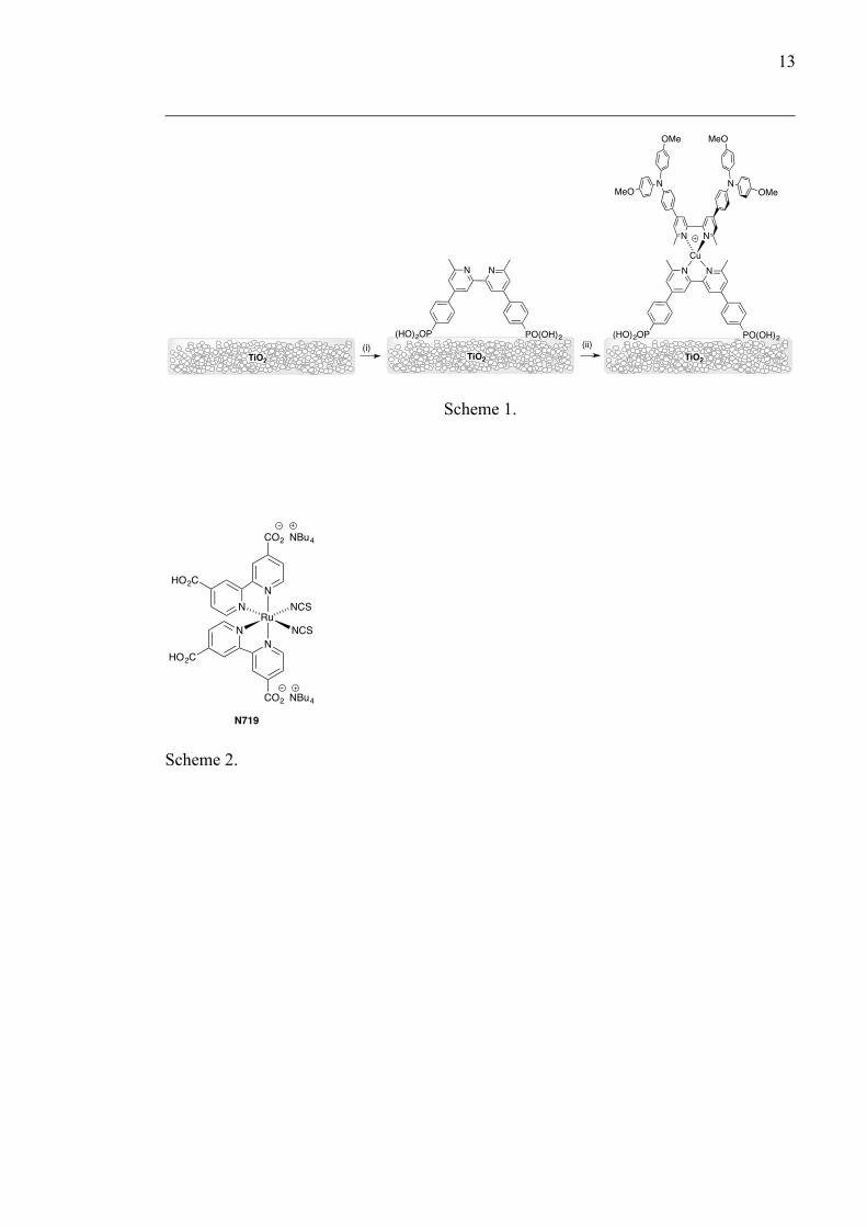
In contrast to the strategy of the Odobel group in which heteroleptic copper(I)
dyes are synthesised by the HETPHEN approach and subsequently anchored to the TiO2
surface [9,10], we have developed a stepwise assembly process in which the electrode is
sequentially dipped into solutions of the anchoring ligand and then of a homoleptic
complex [Cu(Lancillary)2][PF6] [4]. In DSSC s in which an I–/I3– electrolyte is combined
with copper(I)-containing dyes, a commonly observed phenomenon is for the efficiency
of the DSSC to improve over a period of several days [8,11,12]. This observation is
reproduced when duplicate DSSC s are tested. This ripening effect has also been
documented for ruthenium(II) dyes and is interpreted in terms of disaggregation and
reorganization of the dye on the semi-conductor surface [13,14,15]. It is desirable that
DSSCs exhibit their maximum performance immediately after assembly and retain this
3
efficiency throughout their usable life-cycles. Most reports of copper(I) photosensitizers
have focused on enhancing performance through structural modification of the dye.
However, progress in this field will only be possible by more detailed investigations of
other critical factors including the electrolyte [16,17], use of co-adsorbants [18] and
solvent used in the dye bath [11].
We report here the effects of changing the concentration of the solution during the
final step of dye assembly (Scheme 1). For adsorption of the standard dye N719, dye
aggregation is prevented by using suitably dilute solutions, with concentrations <0.4 mM
leading to the dye being adsorbed as monomers [14], but we are not aware of systematic
studies of varying the concentration of copper(I)-based dyes. In this work, we use
phosphonic acid 1 (Scheme 1) as the anchoring ligand; the incorporation of a phenylene
spacer between the bpy and phosphonic acid units improves the performance of the
[Cu(Lanchor)(Lancillary)]+ dye [8]. For the ancillary ligand, we selected 2 (Scheme 1) which
contains peripheral hole-transport triphenylamino-dendrons and is a promising candidate
for incorporation into DSSCs [11].
<Scheme 1 to come here>
2. Experimental
2.1 Chemicals
Ligands 1 [8] and 2 [11] and the complex [Cu(2)2][PF6] [11] were prepared as previously
described.
2.2 DSSC fabrication
4
DSSCs were prepared following a similar procedure to that detailed by Grätzel and
coworkers [19,20]. Solaronix Test Cell Titania Electrodes were used for the photoanodes.
These electrodes were washed with EtOH and sintered at 450o C for 30 min, cooled to
≈80oC, and then dipped into a 1 mM DMSO solution of the anchoring ligand 1 for 1 day
(24 h). The electrode was removed from the solution, washed with DMSO and EtOH and
dried with a heat gun (60 °C). The functionalized electrode was then dipped into a 2.0,
1.0, 0.5 or 0.1 mM MeCN solution of [Cu(2)2][PF6] for 3 days. Each reference cell was
prepared by dipping a commercial electrode (see above) in a 0.3 mM EtOH solution of
standard dye N719 (Solaronix) for 3 days. After the dipping period, each electrode was
washed with the same solvent used in the dipping process and dried at 60 °C (heat gun).
Solaronix Test Cell Platinum Electrodes were used for the photocathodes, and any
volatile organic impurities were removed by heating for 30 min at 450 oC (heating plate).
The dye-covered TiO2 electrode and Pt counter electrode were assembled using
thermoplast hot-melt sealing foil (Solaronix Test Cell Gaskets) by heating while pressing
them together. The electrolyte was introduced into the DSSC by vacuum backfilling and
comprised LiI (0.1 mol dm–3), I2 (0.05 mol dm–3), 1-methylbenzimidazole (0.5 mol dm–3)
and 1-butyl-3-methylimidazolinium iodide (0.6 mol dm–3) in 3-methoxypropionitrile. The
hole in the counter electrode was sealed using hot-melt sealing foil (Solaronix Test Cell
Sealings) and a cover glass (Solaronix Test Cell Caps).
2.3 DSSC and external quantum efficiency (EQE) measurements
The solar cell measurements and testing protocol was performed using fully masked cells.
A black coloured copper sheet was used for masking with a single aperture of average
area 0.06012 cm2 (standard deviation of 1%) placed over the dye-sensitized TiO2 circle.
The area of the aperture in the mask was smaller than the active area of the TiO2 (0.36
5
cm2). For complete masking, tape was also applied over the edges and rear of cell.
Measurements were made by irradiating from behind using as a light source a SolarSim
150 instrument (100 mW cm–2 = 1 sun). The power of the simulated light was calibrated
by using a silicon reference cell.
The external quantum efficiency (EQE) measurements were performed on a Spe-
Quest quantum efficiency setup from Rera Systems (Netherlands) equipped with a 100 W
halogen lamp (QTH) and a lambda 300 grating monochromator from Lot Oriel. The
monochromatic light was modulated to 3Hz using a chopper wheel from ThorLabs. The
cell response was amplified with a large dynamic range IV converter from CVI Melles
Griot and then measured with a SR830 DSP Lock-In amplifier from Stanford Research.
3 Results and discussion
3.1 J–V characteristics and efficiencies of DSSCs using different concentrations of
[Cu(2)2][PF6]
The strategy shown in Scheme 1 was used to assemble the heteroleptic copper(I) dye
anchored to the photoanode. Phosphonic acid 1 was adsorbed onto the TiO2/FTO-coated
glass plate and the electrode was left in the DMSO solution of 1 for one day. In the
second step in Scheme 1, the functionalized electrode was immersed in an MeCN
solution of the homoleptic complex [Cu(2)2][PF6] for 3 days, and concentrations of these
solutions ranged from 0.1 to 2.0 mM. An I3–/I– electrolyte was used and fully masked
DSSCs [21] were fabricated along with a reference DSSC containing standard dye N719
(Scheme 2). Measurements were made on the day of sealing the cells (day 0), and one,
two and three days afterwards, and the performance data of the DSSCs are summarized in
Table 1. The final column in Table 1 gives a relative efficiency with respect to N719 set
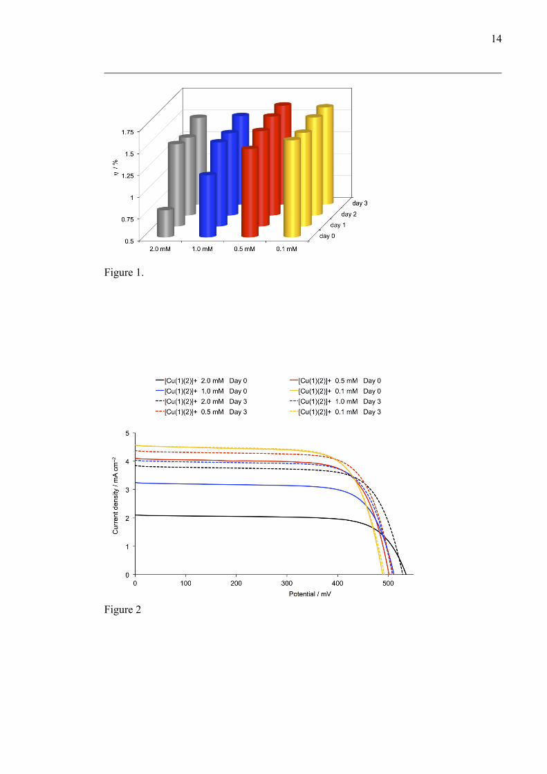
to an arbitrary 100% [22]. The trends in the overall efficiencies (η) are summarized in

6
Figure 1. Figure 2 shows the J–V curves for the DSSCs; all DSSCs exhibit good fill
factors of 72–74%.
< Scheme 2 to come here>
<Figure 1 to come here>
<Table 1 to come here>
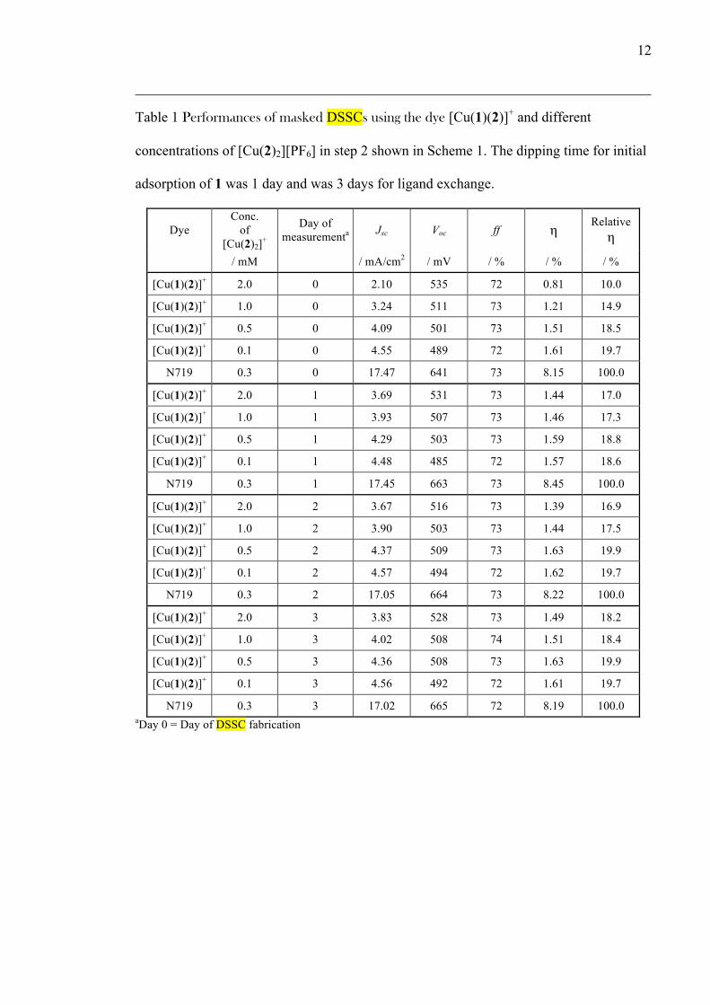
On the initial day, the highest efficiency (η = 1.61% with respect to 8.15% for
N719) is observed for the dye assembled using the most dilute solution of [Cu(2)2][PF6]
(0.1 mM). The more dilute the solution of [Cu(2)2][PF6] is, the higher the value of η for
the [Cu(1)(2)]+ dye, and this correlates with a higher current density (JSC). In contrast, the
highest VOC was observed with the most concentrated [Cu(2)2][PF6] solution.
Figure 1 illustrates that the DSSC containing the [Cu(1)(2)]+ dye made with the
lowest concentration of [Cu(2)2][PF6] exhibits a near constant efficiency over the four
day period, consistent with the attainment of an optimal JSC immediately after sealing the
cells (Figures 1 and 3). In contrast, the [Cu(1)(2)]+ dyes assembled using 2.0, 1.0 and 0.5
mM dye solutions of [Cu(2)2][PF6] show ripening effects with enhanced JSC leading to
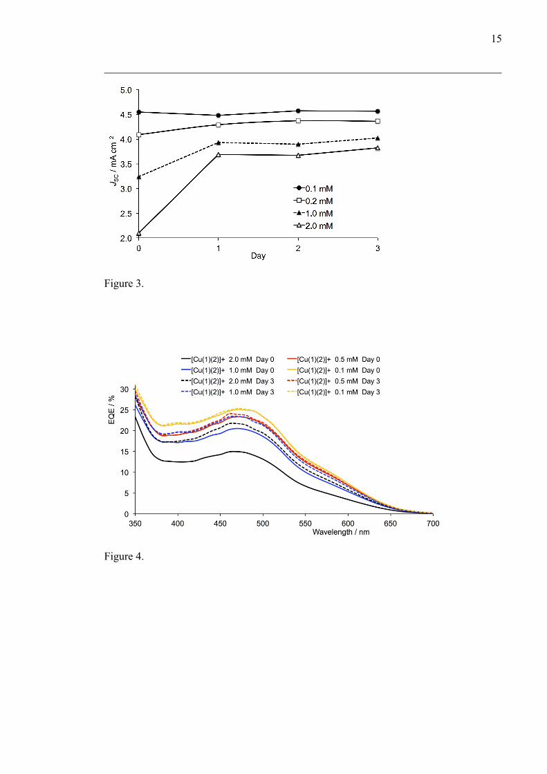
improved η. Figure 3 shows that the enhancement in JSC (and thus in η, Figure 1) over
time depends on the concentration of [Cu(2)2][PF6] in the dye bath. The most pronounced
increase in efficiency occurs for the device prepared using the most concentrated (2.0
mM) solution for which JSC increases from 2.10 to 3.83 mA cm–2– and η from 0.81 to 1.49
% from day 0 to day 3. Figure 3 illustrates that the time required for an optimal JSC to be
attained is directly related to the concentration of [Cu(2)2][PF6], and these results are
consistent with aggregation of dye molecules when the concentration of [Cu(2)2][PF6] is
7
≥0.5 mM. The most important factor contributing to the immediate peak performance of
the DSSC made with the 0.1 mM solution of the homoleptic complex is the attainment of
an optimum JSC on the initial day (Figure 3). Figure 3 also shows that the final JSC is
directly affected by the concentration of the homoleptic complex.
<Figures 2 and 3 near here>
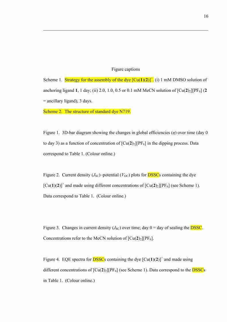
3.2 EQE spectra
The EQE spectra in Figure 4 represent the evolution in JSC over time. All cells exhibit a
similar curve shape with a λmax = 470 nm. On the day of DSSC fabrication, the highest
and lowest EQEs (≈25% and 15%) were obtained for the devices prepared using the most
dilute (0.1 mM) and most concentrated (2.0 mM) solutions of [Cu(2)2][PF6], respectively.
Figure 4 illustrates that a significant enhancement in EQEmax is observed for the DSSC
made using the most concentrated solution of homoleptic complex, and that the
improvement in EQEmax is less the more dilute the solution becomes. For the dye
assembled using the 0.1 mM solution, optimum EQEmax is achieved immediately.
<Figure 4 here>
4 Conclusions
To date, studies of simple factors that affect the performance of DSSCs containing
copper(I)-based sensitizers have been few. An established protocol for assembling
heteroleptic copper(I) bis(diimine) dyes on a TiO2 surface inolves ligand exhange

8
between an anchored diimine ligand and a homoleptic [Cu(Lancillary)2]+ complex. In this
work, we have established that the concentration of [Cu(Lancillary)2]+ has a profound
influence upon the rate at which an optimum JSC is attained and on the actual value of
JSC. This necessarily impacts upon the global efficiency of the DSSCs. Coupled with the
use of a 1 mM DMSO solution of anchoring ligand 1, the best performing solar cells are
achieved using a 0.1 mM MeCN solution of [Cu(2)2][PF6]. Although DSSCs made with a
0.5 mM solution ultimately perform with a similar efficiency, there is a delay of two days
before optimum performance is observed.
Acknowledgements
We gratefully acknowldge the European Research Council (Advanced Grant 267816
LiLo), the Swiss National Science Foundation, and the University of Basel for financial
support. We thank Dr Biljana Bozic-Weber and Sebastian Fürer for helpful discussions.
References
[1] M. Grätzel, Solar Energy Conversion by Dye-Sensitized Photovoltaic Cells, Inorg.
Chem. 44 (2005) 6841–6851.
[2] A. Reynal, E. Palomares, Ruthenium Polypyridyl Sensitisers in Dye Solar Cells
Based on Mesoporous TiO2, Eur. J. Inorg. Chem. (2011) 4509–4526.
[3] A. Mishra, M. K. R. Fischer, P. Bäuerle, Metal-Free Organic Dyes for Dye-
Sensitized Solar Cells: From Structure: Property Relationships to Design Rules,
Angew. Chem. Int. Ed. 48 (2009) 2474–2499.
9
[4] B. Bozic-Weber, E. C. Constable, C. E. Housecroft, Light harvesting with Earth
abundant d-block metals: towards a sustainable materials chemistry, Coord. Chem.
Rev. 257 (2013) 3089-3106.
[5] T. E. Hewat, L. J. Yellowlees, N.Robertson, Neutral copper(I) dipyrrin complexes
and their use as sensitizers in dye-sensitized solar cells, Dalton Trans. 43 (2014)
4127–4136.
[6] K. A. Wills, H. J. Mandujano-Ramírez, G. Merino, D. Mattia, T. Hewat, N.
Robertson, G. Oskam, M. D. Jones, S. E. Lewis, P. J. Cameron, Investigation of a
copper(I) biquinoline complex for application in dye-sensitized solar cells, RSC
Adv. 3 (2013) 23361–23369.
[7] A. Colombo, C. Dragonetti, D. Roberto, A. Valore, P. Biagini, F. Melchiorre, A
simple copper(I) complex and its application in efficient dye-sensitized solar cells
Inorg. Chim. Acta 407 (2013) 204–209.
[8] B. Bozic-Weber, S. Y. Brauchli, E. C. Constable, S. O. Fürer, C. E. Housecroft, F.
J. Malzner, I. A. Wright, J. A. Zampese, Improving the photoresponse of copper(I)
dyes in dye-sensitized solar cells by tuning ancillary and anchoring ligand modules,
Dalton Trans. 42 (2013) 12293–12308.
[9] M. Sandroni, M. Kayanuma, A. Planchat, N. Szuwarski, E. Blart, Y. Pellegrin, C.
Daniel, M. Boujtita, F. Odobel, First application of the HETPHEN concept to new
heteroleptic bis(diimine) copper(I) complexes as sensitizers in dye sensitized solar
cells, Dalton Trans. 42 (2013) 10818–10827.
[10] M. Sandroni, L. Favereau, A. Planchat, H. Akdas-Kilig, N. Szuwarski, Y.
Pellegrin, E. Blart, H. Le Bozec, M. Boujtita, F. Odobel, Heteroleptic copper(I)
10
polypyridine complexes as efficient sensitizers for dye sensitized solar cells, J.
Mater. Chem. A 2 (2014) 9944–9947.
[11] B. Bozic-Weber, S. Y. Brauchli, E. C. Constable, S. O. Fürer, C. E. Housecroft, I.
A. Wright, Hole-transport functionalized copper(I) dye sensitized solar cells, Phys.
Chem. Chem. Phys. 15 (2013) 4500-4504.
[12] B. Bozic-Weber, V. Chaurin, E. C. Constable, C. E. Housecroft, M. Meuwly, M.
Neuburger, J. A. Rudd, E. Schönhofer, L. Siegfried, Exploring copper(I)-based
dye-sensitized solar cells: a complementary experimental and TD-DFT
investigation, Dalton Trans. 41 (2012) 14157-141169.
[13] B. Wenger, M. Grätzel, J.-E. Moser, Rationale for kinetic heterogeneity of ultrafast
light-induced electron transfer from Ru(II) complex sensitizers to nanocrystaline
TiO2, J. Am. Chem. Soc. 127 (2005) 12150–12151.
[14] B. Wenger, M. Grätzel, J.-E. Moser, Origin of the kinetic heterogeneity of ultrafast
light-induced electron transfer from Ru(II)-complex dyes to nanocrystaline
semiconducting particles, Chimia 59 (2005) 123–125.
[15] V. K. Thorsmølle, B. Wenger, J. Teuscher, C. Bauer, J.-E. Moser, Dynamics of
photoinduced interfacial electron transfer and charge transport in dye-sensitized
mesoscopic semiconductors, Chimia 61 (2007) 631–634.
[16] B. Bozic-Weber, E. C. Constable, S. O. Fürer, C. E. Housecroft, L. J. Troxler and J.
A. Zampese, Copper(I) dye-sensitized solar cells with [Co(bpy)3]2+/3+ electrolyte,
Chem. Commun. 49 (2013) 7222–7224.
[17] L. N. Ashbrook, C. M. Elliott, Dye-sensitized solar cell studies of a donor-
appended bis(2,9-dimethyl-1,10-phenthroline) Cu(I) dye paired with a cobalt-based
mediator, J. Phys. Chem. C 117 (2013) 3853–3864.

11
[18] C. L. Linfoot, P. Richardson, T. E. Hewat, P. Moudam, M. M. Forde, A. Collins, F.
White, N. Robertson, Substituted [Cu(I)(POP)(bipyridyl)] and related complexes:
synthesis, structure, properties and application to dye-sensitized solar cells, Dalton
Trans. 39 (2010) 8945–8956.
[19] S. Ito, T. N. Murakami, P. Comte, P. Liska, C. Grätzel, M. K. Nazeeruddin, M.
Grätzel, Fabrication of thin film dye sensitized solar cells with solar to electric
power conversion efficiency over 10%, Thin Solid Films 516 (2008) 4613–4619.
[20] S. Ito, P. Chen, P. Comte, M. K. Nazeeruddin, P. Liska, P. Péchy, M. Grätzel,
Fabrication of screen-printing pastes from TiO2 powders for dye-sensitised solar
cells, Prog. Photovoltaics Res. Appl. 15 (2007) 603–612.
[21] H. J. Snaith, How should you measure your excitonic cells? Energy Envir. Sci. 5
(2012) 6513.
[22] F. J. Malzner, S. Y. Brauchli, E. Schönhofer, E. C. Constable and C. E. Housecroft,
To deprotect or not to deprotect: phosphonate ester versus phosphonic acid anchor
ligands in copper(I)-based dye-sensitized solar cells, Polyhedron (2014) doi:
10.1016/j.poly.2014.05.019.
12
Table 1 Performances of masked DSSCs using the dye [Cu(1)(2)]+ and different
concentrations of [Cu(2)2][PF6] in step 2 shown in Scheme 1. The dipping time for initial
adsorption of 1 was 1 day and was 3 days for ligand exchange.
Dye Conc.
of [Cu(2)2]+
Day of measurementa Jsc Voc ff η Relative
η
/ mM / mA/cm2 / mV / % / % / %
[Cu(1)(2)]+ 2.0 0 2.10 535 72 0.81 10.0
[Cu(1)(2)]+ 1.0 0 3.24 511 73 1.21 14.9
[Cu(1)(2)]+ 0.5 0 4.09 501 73 1.51 18.5
[Cu(1)(2)]+ 0.1 0 4.55 489 72 1.61 19.7
N719 0.3 0 17.47 641 73 8.15 100.0
[Cu(1)(2)]+ 2.0 1 3.69 531 73 1.44 17.0
[Cu(1)(2)]+ 1.0 1 3.93 507 73 1.46 17.3
[Cu(1)(2)]+ 0.5 1 4.29 503 73 1.59 18.8
[Cu(1)(2)]+ 0.1 1 4.48 485 72 1.57 18.6
N719 0.3 1 17.45 663 73 8.45 100.0
[Cu(1)(2)]+ 2.0 2 3.67 516 73 1.39 16.9
[Cu(1)(2)]+ 1.0 2 3.90 503 73 1.44 17.5
[Cu(1)(2)]+ 0.5 2 4.37 509 73 1.63 19.9
[Cu(1)(2)]+ 0.1 2 4.57 494 72 1.62 19.7
N719 0.3 2 17.05 664 73 8.22 100.0
[Cu(1)(2)]+ 2.0 3 3.83 528 73 1.49 18.2
[Cu(1)(2)]+ 1.0 3 4.02 508 74 1.51 18.4
[Cu(1)(2)]+ 0.5 3 4.36 508 73 1.63 19.9
[Cu(1)(2)]+ 0.1 3 4.56 492 72 1.61 19.7
N719 0.3 3 17.02 665 72 8.19 100.0 aDay 0 = Day of DSSC fabrication
13
Scheme 1.
Scheme 2.
OO OHOHTiO2
N N
(HO)2OP PO(OH)2OO OHOHTiO2
(i) OO OHOHTiO2
N N
(HO)2OP PO(OH)2(ii)
Cu
N
NMeO
OMe
N
NOMe
MeO
RuNCS
NCS
NN
NN
CO2 NBu4
HO2C
HO2C
CO2 NBu4
N719
14
Figure 1.
Figure 2
15
Figure 3.
Figure 4.
16
Figure captions
Scheme 1. Strategy for the assembly of the dye [Cu(1)(2)]+. (i) 1 mM DMSO solution of
anchoring ligand 1, 1 day; (ii) 2.0, 1.0, 0.5 or 0.1 mM MeCN solution of [Cu(2)2][PF6] (2
= ancillary ligand), 3 days.
Scheme 2. The structure of standard dye N719.
Figure 1. 3D-bar diagram showing the changes in global efficiencies (η) over time (day 0
to day 3) as a function of concentration of [Cu(2)2][PF6] in the dipping process. Data
correspond to Table 1. (Colour online.)
Figure 2. Current density (JSC)–potential (VOC) plots for DSSCs containing the dye
[Cu(1)(2)]+ and made using different concentrations of [Cu(2)2][PF6] (see Scheme 1).
Data correspond to Table 1. (Colour online.)
Figure 3. Changes in current density (JSC) over time; day 0 = day of sealing the DSSC.
Concentrations refer to the MeCN solution of [Cu(2)2][PF6].
Figure 4. EQE spectra for DSSCs containing the dye [Cu(1)(2)]+ and made using
different concentrations of [Cu(2)2][PF6] (see Scheme 1). Data correspond to the DSSCs
in Table 1. (Colour online.)

17