Embed Size (px)
Citation preview
Concept of Operations and Policy Implications
for Unmanned Aircraft Systems Use
for Traffic Incident Management (UAS-TIM)
Final Report
PRC 15-69F

2
Concept of Operations and Policy Implications
for Unmanned Aircraft Systems Use
for Traffic Incident Management (UAS-TIM)
Texas A&M Transportation Institute
PRC 15-69F
March 2017
Author
Charles R. Stevens, Jr., P.E., PTOE
Copies of this publication have been deposited with the Texas State Library in compliance with the
State Depository Law, Texas Government Code §441.101-106.
3
Table of Contents
List of Figures ................................................................................................................................ 5
Executive Summary ...................................................................................................................... 6
Concept of Operations ................................................................................................................. 6
Regulations .................................................................................................................................. 6
Introduction ................................................................................................................................... 8
Statement of Problem .................................................................................................................. 8
Project Background ..................................................................................................................... 9
Purpose and Organization of Document ..................................................................................... 9
UAS Use in Transportation ........................................................................................................ 11
Background ............................................................................................................................... 11
Examples of DOT Use of UAS ................................................................................................. 11
Arkansas State Highway and Transportation Department .................................................................................. 11 Virginia Department of Transportation .............................................................................................................. 11 Florida Department of Transportation ................................................................................................................ 11 Ohio Department of Transportation .................................................................................................................... 12 Washington Department of Transportation......................................................................................................... 12 Utah Department of Transportation .................................................................................................................... 15 Georgia Department of Transportation ............................................................................................................... 15 California Department of Transportation ............................................................................................................ 15 Michigan Department of Transportation............................................................................................................. 15 North Carolina Department of Transportation .................................................................................................... 16 West Virginia Division of Highways .................................................................................................................. 16
Other Documented Transportation Applications ...................................................................... 16
Incident Management and Crash Mapping ......................................................................................................... 16 Crash Mapping.................................................................................................................................................... 16 High-Definition Imagery for Traffic Flow Management .................................................................................... 17 Airborne Road Traffic Monitoring with Radar ................................................................................................... 17 Real-Time Road Detection ................................................................................................................................. 17 Statistical Profile Generation from Traffic Monitoring Using Real-Time UAS-Based Video Data ................... 17 Vehicle Detection from Aerial Imagery.............................................................................................................. 17 Real-Time Video Relay for UAS Traffic Surveillance Systems through Available Communications
Networks .................................................................................................................................................... 17 Roadway Traffic Monitoring from a UAS .......................................................................................................... 18
Perceived Needs for UAS-TIM .................................................................................................. 19
Need 1: Incident Monitoring (Incident Command Participation) ............................................. 19
Need 2: Situational Awareness ................................................................................................. 20
Secondary Crash Monitoring .............................................................................................................................. 20 Multiple Route Monitoring (Previously Unmonitored) ...................................................................................... 21 Traffic Queue Monitoring ................................................................................................................................... 21
Need 3: Quick Clearance and Recovery ................................................................................... 21
Incident Detection and Confirmation .................................................................................................................. 21 Monitoring of Incident Scene ............................................................................................................................. 21 Fatal Crash Investigation .................................................................................................................................... 22

4
Concept of Operations ................................................................................................................ 23
UAS-TIM Goals ........................................................................................................................ 23
Components ............................................................................................................................... 23
Capabilities and Functions of UAS-TIM .................................................................................. 24
UAS-TIM Capabilities ........................................................................................................................................ 24 UAS-TIM Functions ........................................................................................................................................... 25 Expanded UAS-TIM Functionality ..................................................................................................................... 26
Operational Scenarios ............................................................................................................... 26
Operational Scenario 1: Incident Monitoring ..................................................................................................... 26 Operational Scenario 2: Situational Awareness .................................................................................................. 28 Operational Scenario 3: Difficult Terrain, Safety, or Maneuverability .............................................................. 29 Operational Scenario 4: Natural Event ............................................................................................................... 31 Operational Scenario 5: Fatal Crash Scene Mapping ......................................................................................... 32
Architecture ................................................................................................................................. 34
Policy Considerations ................................................................................................................. 35
FAA Rules and Regulations ...................................................................................................... 35
Public Aircraft .................................................................................................................................................... 35 Civil (Private) Aircraft ........................................................................................................................................ 35
Texas Laws and Legislation ...................................................................................................... 36
Texas House Bill 912 .......................................................................................................................................... 36 Texas House Bill 1481 ........................................................................................................................................ 37 Texas House Bill 2167 ........................................................................................................................................ 38
Potential State Regulations for UAS Operations ...................................................................... 38
Operating UAS over Private Property ....................................................................................... 39
Findings and Next Steps ............................................................................................................. 40
Findings ..................................................................................................................................... 40
Next Steps ................................................................................................................................. 40
Evaluation Protocol ............................................................................................................................................ 40 Agency Participation .......................................................................................................................................... 40 FAA Authorization and Safe Operation.............................................................................................................. 40 Selection of UAS Service Providers ................................................................................................................... 41 Policy and Legal Impacts .................................................................................................................................... 41 Continuing Research ........................................................................................................................................... 41
References .................................................................................................................................... 42
Appendix—Texas Urban Airspace Analyses............................................................................ 45

5
List of Figures
Figure 1. Ohio/Indiana UAS Center Flight Operation Procedures. .............................................. 13
Figure 2. Ohio/Indiana UAS Center Test Flight Steps and Processes. ......................................... 14
Figure 3. The Yamaha R-Max. ..................................................................................................... 14
Figure 4. SH 6 at US 290—Pan, Tilt, and Zoom versus 400-Foot Elevation View. .................... 20
Figure 5. Example UAS Response Unit. ...................................................................................... 24
Figure 6. Operational Scenario 1: Incident Monitoring. ............................................................... 27
Figure 7. Operational Scenario 2: Situational Awareness. ........................................................... 28
Figure 8. Operational Scenario 3: Difficult Terrain, Safety, or Maneuverability. ........................ 30
Figure 9. Operational Scenario 4: Natural Event. ......................................................................... 31
Figure 10. Operational Scenario 5: Fatal Crash Scene Mapping. ................................................. 32
Figure 11. National ITS Service Package Graphic for TIM Systems. .......................................... 34
Figure 12. UAS-TIM Architecture. .............................................................................................. 34
Figure 13. Austin Airspace Analysis. ........................................................................................... 45
Figure 14. College Station Airspace Analysis. ............................................................................. 45
Figure 15. Dallas-Fort Worth Airspace Analysis. ........................................................................ 46
Figure 16. El Paso Airspace Analysis. .......................................................................................... 46
Figure 17. Houston Airspace Analysis. ........................................................................................ 47
Figure 18. Rio Grande Valley Airspace Analysis. ........................................................................ 47
Figure 19. San Antonio Airspace Analysis. .................................................................................. 48

6
Executive Summary
Texas freeways experience considerable traffic congestion—some from high traffic volumes and
some from traffic incidents, both minor (e.g., crashes, stalls, and road debris) and major (e.g.,
vehicle rollovers, chemical spills, flooding, and hurricane evacuations). Incidents can literally
bring freeways systems to a standstill, which results in significant economic impact for Texas
drivers and businesses. Quick response and clearance of traffic incidents through traffic incident
management (TIM) practices are proven methods of restoring roadway capacity and increasing
mobility on urban freeways.
Transportation agencies and emergency responders are continually seeking new technologies and
systems (especially for major incidents) that can improve incident response, monitoring, and
clearance. One such system/technology under consideration is unmanned aircraft systems (UAS).
Commonly referred to as drones in military applications, public and civil UAS could prove to be
a flexible and useful tool for transportation agencies and emergency responders.
Concept of Operations
To better understand the policy implications, the Texas A&M Transportation Institute developed
a concept of operations (ConOps), an early step in the systems engineering process, with a focus
on using UAS as an intelligent transportation systems tool to enhance TIM and provide quick
and accurate information from the scene of a traffic incident: UAS-TIM. The ConOps provides a
roadmap for the validation of UAS abilities to enhance monitoring, situational awareness, and
safety when compared to traditional fixed-location cameras and expensive helicopters.
Regulations
UAS-TIM comes with a number of policy questions. The federal government has recently issued
extensive regulations (whose implications are currently beyond the scope of this research effort).
Texas state law addresses drones in several areas, including limitations on use of the device and
use of the information gathered from the device.
Texas state law is not clear on whether agencies can use UAS-TIM or what limitations the
Federal Aviation Administration (FAA) might place on UAS-TIM. For example, while
exemptions exist for work on behalf of a law enforcement authority, including when
investigating the scene of a human fatality or motor vehicle accident on a state highway, existing
language presupposes UAS use only by law enforcement authorities or after a determination of
the cause of incident-related congestion.
Researchers expect that agencies will contract with UAS service providers, necessitating
clarification of the law’s application to service providers. For the validation phase of UAS-TIM,
service providers have concerns about the permissions required to park a trailer and have the
drone take off from private property adjacent to highway right of way, as well as the
collection/retention of private images taken on or adjacent to the right of way incidental to the

7
cause of the incident. These issues are important to UAS service providers because FAA has the
authority to revoke their commercial exemptions for UAS operations if they are found in
violation of state laws.

8
Introduction
Texas freeways experience considerable traffic congestion—some from high traffic volumes and
some from traffic incidents, both minor (e.g., crashes, stalls, and road debris) and major (e.g.,
vehicle rollovers, chemical spills, flooding, and hurricane evacuations). Incidents can literally
bring freeways systems to a standstill, which results in significant economic impact for Texas
drivers and businesses. Quick response and clearance of traffic incidents through traffic incident
management (TIM) practices are proven methods of restoring roadway capacity and increasing
mobility on urban freeways.
Transportation agencies and emergency responders are continually seeking new technologies and
systems (especially for major incidents) that can improve incident response, monitoring, and
clearance. One such system/technology under consideration is unmanned aircraft systems (UAS).
Commonly referred to as drones in military applications, civil UAS could potentially prove to be
a flexible and useful tool for transportation agencies and emergency responders.
Statement of Problem
Freeway incidents cause significant congestion and motorist delay, resulting in approximately
25 percent of all non-recurring congestion. This non-recurring congestion greatly reduces
capacity and overall system reliability (1). Agencies continue to work toward minimizing the
impact of non-recurring congestion through various means; the most notable is formal TIM
practices.
According to the Federal Highway Administration (FHWA), TIM “consists of a planned and
coordinated multidisciplinary process to detect, respond to, and clear traffic incidents so that
traffic flow may be restored as safely and quickly as possible” (2). The FHWA document Traffic
Incident Management Gap Analysis Primer (2) says that the goals of TIM are to:
Promote the safety of motorists, crash victims, and incident responders.
Reduce the time for incident detection and verification.
Reduce response time (the time for response personnel and equipment to arrive at the
scene).
Exercise proper and safe on-scene management of personnel and equipment, while
keeping as many lanes as possible open to traffic.
Conduct an appropriate response, investigation, and safe clearance of an incident.
Reduce clearance time (the time required to remove the incident from the roadway).

9
Provide timely and accurate information to the public that enables them to make
informed choices.
Get traffic moving again as soon as possible after a partial or complete roadway closure
while managing the affected traffic until normal conditions are restored.
As agencies work toward achieving these goals, additional applications and tools are constantly
emerging and considered for their feasibility to enhance an agency’s ability to manage an
incident more effectively and reduce congestion and motorist delay. One such potential emerging
incident management tool is UAS, which is an all-encompassing term that includes the aircraft,
the ground station and controller, and the communication systems used by the ground station to
operate the aircraft.
Project Background
Researchers examined the potential deployment of UAS as a way to improve response,
monitoring, and clearance of traffic incidents. Since improved TIM would most likely reduce
clearance times and the resulting non-recurring congestion, researchers developed a project
vision to facilitate the acceptance and deployment of UAS by transportation agencies. To
accomplish this, the project was split into two phases for funding purposes:
Phase 1: development of a systems engineering document referred to as a Concept of
Operations (ConOps) summarized by this report.
Phase 2: pilot demonstration and validation, which is underway.
To help UAS gain acceptance as a TIM tool, researchers acknowledged that agencies and
partnerships such as Houston Transtar would primarily consider UAS an intelligent
transportation system (ITS) deployment and require proper systems engineering investigation.
Therefore, researchers took the following actions:
In Phase 1, researchers took an agency-agnostic approach in developing the ConOps.
In Phase 2, researchers will validate the technology and investigate how recent the
Federal Aviation Administration (FAA) rules and regulations and state laws could
influence the actions of commercial UAS service providers and operators for
transportation purposes. Phase 2 will also provide insight into the potential safety and
operational concerns of operating near and over live traffic.
Purpose and Organization of Document
The purpose of this document is to provide a high-level, agency-agnostic, and location-
independent ConOps for using UAS as an ITS tool for improved traffic incident management
(UAS-TIM). This document assumes that agencies will be able to use the UAS-TIM for real-
10
time incident monitoring, situational awareness, and quick clearance (including fatal crash scene
mapping).
A typical ConOps defines the operational mission of a system or group of systems (as a project)
and identifies the requirements necessary to achieve that mission. A ConOps should define:
1. The goals, objectives, and capabilities of each system or group of systems.
2. The roles and responsibilities of the implementing agency and affected stakeholders (3).
For UAS-TIM and this high-level ConOps, there is no assigned agency or regional area for
deployment. Therefore, this document will concentrate on the first purpose, defining the goals,
objectives, and capabilities of the UAS-TIM. This document discusses:
Current uses of UAS in transportation.
Perceived needs for UAS-TIM.
The development of ConOps components including goals, functions, key concepts, and
operational scenarios.
Potential UAS-TIM system architecture impacts.
Potential policy concerns.
Next steps.

11
UAS Use in Transportation
Background
Prior to developing a ConOps, researchers had to understand the current status of UAS, their
applications to transportation, and, more importantly, state department of transportation (DOT)
experience using the technology. Researchers completed an extensive literature review in spring
2016 using Texas A&M University resources. Researchers found that several DOTs have
investigated or experimented with using UAS for transportation purposes, mainly for aerial
imagery and condition assessment. However, several project reports indicated potential UAS use
for traffic monitoring and volume determination.
Examples of DOT Use of UAS
Civil UAS have been gaining momentum for use in transportation because they have become
more capable, smaller, and more affordable. UAS uses range from simple video monitoring to
pavement crack detection using LIDAR. Not including the current efforts by the Texas
Department of Transportation (TxDOT) and the Texas A&M Transportation Institute (TTI),
11 DOTs have investigated or are currently investigating UAS applications or are sponsoring
UAS research. Due to the rapid pace at which transportation agencies are investigating UAS for
uses in transportation, researchers expect that an update to this section will be necessary and
completed during Phase 2 of the project.
Arkansas State Highway and Transportation Department
In 2010, the Arkansas State Highway and Transportation Department research section completed
a project investigating mobile systems to monitor traffic from above. The project compared
literature about UAS, a mobile mast-mounted camera, and a tethered helium balloon technology
for use in collecting high-definition (HD) video and pictures to quantify turning movements,
traffic volumes, vehicle headways, queue lengths, and vehicle classification, and to calibrate
simulation models. Prior to the testing and demonstration phase of the project, the DOT
abandoned UAS as a possible system citing FAA restrictions and time constraints (4).
Virginia Department of Transportation
In 2002, the National Consortium on Remote Sensing in Transportation, in cooperation with the
Virginia Department of Transportation, demonstrated airborne data acquisition systems for real-
time traffic surveillance, monitoring of traffic incidents and signals, and environmental condition
assessment of roadside areas (5). In August 2014, Virginia Tech announced that its unmanned
aircraft test site was fully operational. UAS demonstrations were carried out on the DOT’s Smart
Road, a 2.2-mile section of limited-access roadway used for testing new technologies (6).
Florida Department of Transportation
Over a span of four years, the University of Florida completed an airborne traffic monitoring
proof-of-concept study for the Florida Department of Transportation. The University of Florida
12
selected the Aerosonde make of UAS after engaging over 50 UAS vendors. This project also
focused heavily on communication and obtained the necessary equipment to outfit two
microwave towers. Unfortunately, FAA denied approval of a certificate of authorization (COA)
for this project. The specific points of contention were the “see and avoid”1 and safe landing
issues. Due to these concerns and the denial of the COA, the DOT canceled the project, citing no
solution to the “see and avoid” and safe landing issues (7).
Ohio Department of Transportation
In 2002, Ohio State University performed field experiments in Columbus to determine the
feasibility of collecting data on freeway conditions, intersection movements, network paths, and
parking lots (8). Described as an innovator in 2013, the Ohio Department of Transportation
continued the process of implementing UAS for more efficient and effective operations.
However, the DOT noted that the biggest challenge was obtaining clearance to fly in the national
airspace. Working closely with FAA, the DOT has developed a method to streamline the COA
process (9).
In 2013, the governor of Ohio, John R. Kasich, announced a joint initiative with Indiana to
develop an unmanned aircraft systems center to advance the commercialization of the technology
and support UAS research. The center is formally a component of the Ohio Department of
Transportation; the Ohio Legislature passed a declaration supporting the center. The current
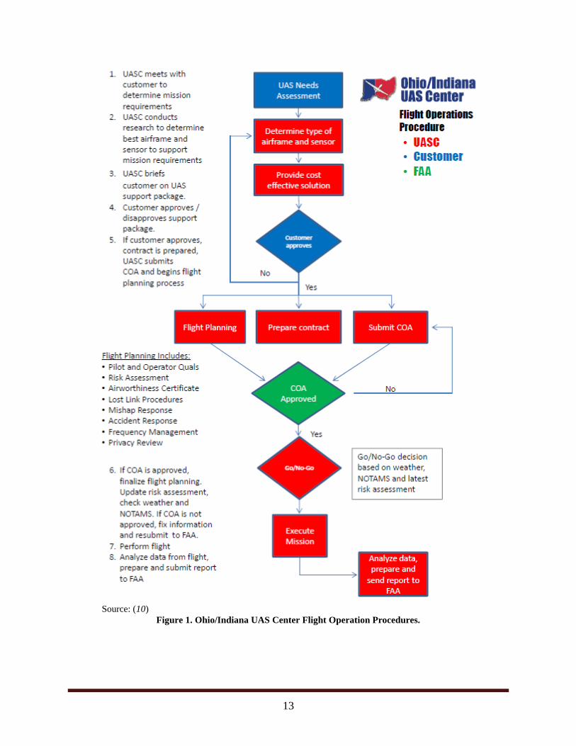
website offers services including flight operations (Figure 1) and flight testing (Figure 2),
including language about pay-based services (10).
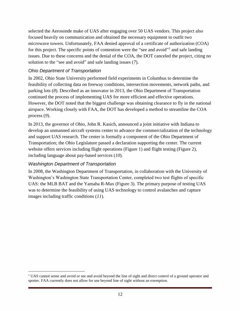
Washington Department of Transportation
In 2008, the Washington Department of Transportation, in collaboration with the University of
Washington’s Washington State Transportation Center, completed two test flights of specific
UAS: the MLB BAT and the Yamaha R-Max (Figure 3). The primary purpose of testing UAS
was to determine the feasibility of using UAS technology to control avalanches and capture
images including traffic conditions (11).
1 UAS cannot sense and avoid or see and avoid beyond the line of sight and direct control of a ground operator and
spotter. FAA currently does not allow for use beyond line of sight without an exemption.
13
Source: (10)
Figure 1. Ohio/Indiana UAS Center Flight Operation Procedures.

14
Source: (10)
Figure 2. Ohio/Indiana UAS Center Test Flight Steps and Processes.
Source: (11)
Figure 3. The Yamaha R-Max.
15
Utah Department of Transportation
Utah State University and the Utah Water Research Lab completed an evaluation of UAS for the
Utah Department of Transportation in 2012. The primary objectives of the project were to use
UAS to capture high-resolution images of construction projects for monitoring and to classify
wetland plant species. Utah State University conducted several flights. Researchers captured
images before, during, and after completion of the Southern Parkway Highway at the Utah
Airport and the Utah Lake Wetlands. The results of the project were favorable, and researchers
concluded that UAS as a tool had value for digital imagery including roadway traffic conditions
and for wetland monitoring and mitigation permitting (12).
Georgia Department of Transportation
In 2014, the Georgia Institute of Technology completed a feasibility study for the Georgia
Department of Transportation, studying the potential of UAS application for DOT operations.
Researchers developed basic goals and information requirements, and proposed five reference
systems for the ability to capture real-time data including:
Flying camera.
Flying total station.
Perching camera.
Medium altitude long endurance.
Complex manipulation.
In addition to developing reference systems, the researchers interviewed 24 Georgia Department
of Transportation staff members and concluded that the primary areas of application were
collecting data, providing information, and making decisions based on the data. The report also
listed future research needs in the areas of economics and intangible benefits (13).
California Department of Transportation
In August 2014, the California Department of Transportation produced a report on the use of
UAS for steep terrain investigation. Initial work focused on previous DOT experiences, the role
of FAA, UAS applications, and training resources. The report discusses prior California
Department of Transportation research for using UAS for bridge inspection in 2008 but indicates
that the DOT had not completed any additional UAS research. The report indicates future
research in the areas of proof-of-concept testing and close monitoring of the FAA regulatory
environment (14).
Michigan Department of Transportation
The Michigan Department of Transportation evaluated five UAS platforms with a combination
of various payloads including optical, thermal, and LIDAR sensors. The DOT directed the
16
evaluation at UAS capabilities to assess critical transportation infrastructure such as bridges,
confined spaces, traffic flow, and roadway assets (15).
North Carolina Department of Transportation
In August 2013, the State of North Carolina approved a test UAS program at North Carolina
State University. In March 2014, the DOT presented a report on unmanned aircraft use to the
North Carolina Legislative Joint Oversight Committee on Information Technology, the Joint
Legislative Transportation Oversight Committee, and the Fiscal Research Division. The report
was in response to the legislative request that included coordination with the chief information
officer and aviation division director of the DOT to develop a proposal for the implementation of
a UAS program. The program listed several areas that would benefit from UAS use including
agriculture, surveying, wildlife monitoring, state infrastructure monitoring, migration
monitoring, and emergency management. A breakdown of the cost of the UAS program was also
provided, estimating a startup cost of $850,000 and recurring annual costs of $435,250 (16).
West Virginia Division of Highways
In 2012, West Virginia University researchers successfully demonstrated that UAS can be a low-
cost solution to providing a stable aerial platform for transportation use. The project, funded
jointly by the Mid-Atlantic Universities Transportation Center and the West Virginia Division of
Highways, used a fixed-wing aircraft to capture aerial images and develop geo-referencing
software (17).
Other Documented Transportation Applications
Incident Management and Crash Mapping
The department of research and development at the Norwegian Air Ambulance Foundation
examined using a remotely piloted aircraft system for major incidents and emergency response.
Researchers tested the system under five extreme cases including a mass casualty traffic
accident, mountain rescue, avalanche with buried victims, fisherman through thin ice, and search
for casualties in the dark. Researchers found that remotely piloted aircraft can be effective
despite payload and other limitations for supporting situation assessment, making decisions, and
exchanging information (18).
Crash Mapping
A study in China developed a UAS-based mapping system to get crash data quickly from a
scene. Researchers deployed a quadcopter to understand the necessary specifications such as
payload, cost, and flight altitude. The system is capable of extracting precise maps of an incident,
and researchers considered the system very useful for complex accidents where multiple vehicles
are involved. Additional safety benefits were determined for facilities with high travel speed and
those incident where agencies might consider it unsafe to investigate the crash scene in person.
The system uses a camera and image-processing software, and researchers suggest the system
could be useful for traffic accident investigations (19).

17
High-Definition Imagery for Traffic Flow Management
A feasibility study by the University of Arizona in cooperation with Ohio State University
investigated the quality of data that operators could receive from a rotary UAS. The project was
successful in showing that UAS could capture HD imagery and track vehicles. Researchers
conducted a two-minute flight, classified vehicles, and determined their direction. Researchers
also estimated parameters such as velocity and tracked distance before developing statistical
error (20).
Airborne Road Traffic Monitoring with Radar
This project used synthetic aperture radar and ground moving-target indication to estimate traffic
flow with radar using a high-altitude UAS (21).
Real-Time Road Detection
The University of California–Berkeley presented a real-time road detection algorithm. The
proposed algorithm can detect roadways in real time by using a snapshot of the target roadway.
The concept is to use UAS technology to capture video, detect road boundaries, and define the
roadway structure. Researchers determined that for this concept to be feasible, the UAS would
have to fly low enough to capture road pavement markings (22).
Statistical Profile Generation from Traffic Monitoring Using Real-Time UAS-Based Video
Data
The eye in the sky project from the University of South Florida proposes the use of small rotary
UAS for collecting real-time data. Agencies can use the data for monitoring traffic in real time,
evaluating traffic patterns, and gathering accurate traffic counts. Researchers attached custom-
made vision systems to the vehicle (including pan and tilt cameras) for dynamic tracking and car
following. Researchers collected video data and calculated traffic occupancy, capacity, and
density. Researchers then fed these parameters into a traffic model to develop future traffic
conditions (23).
Vehicle Detection from Aerial Imagery
Using a rotary-wing UAS, this project focused on the methods to detect vehicles automatically in
two distinct stages:
The first stage used an algorithm looking for man-made objects by feature, density,
clustering, and color.
The second stage used a target classification to reduce false alarms (24).
Real-Time Video Relay for UAS Traffic Surveillance Systems through Available
Communications Networks
A Western Michigan University project focused on methods to relay real-time video for traffic
surveillance purposes. The problem was in relaying the video data to the Michigan Department

18
of Transportation. The streaming video data were too large for available network bandwidths and
as a result had to be compressed using a Windows encoder (25).
Roadway Traffic Monitoring from a UAS
The University of Ohio investigated the use of UAS (BAT III) for the purpose of developing
traffic parameters such as level of service, annual average daily traffic, intersection operations,
traffic flow, and parking. Researchers used two methods of estimating roadway densities: using
still frames and using a series of frames. Researchers also used a geographical information
system to develop roadway lengths and calculate traffic volumes (26).

19
Perceived Needs for UAS-TIM
In 2010, FHWA published a document containing information about best practices in TIM (27)
and listed five functional areas of TIM that face challenges:
Detection and verification.
Traveler information.
Response.
Scene management and traffic control.
Quick clearance and recovery.
Within these functional areas, FHWA listed challenges. UAS-TIM could act as a strategy for the
following areas:
Inaccurate incident reports.
Difficulty of on-scene maneuverability.
Responder safety.
Secondary incidents.
Excess delay.
Lengthy minor-incident clearance.
Lengthy major-incident clearance.
Researchers developed three needs for UAS-TIM based on the findings of the 2010 best
practices report:
Need 1: incident monitoring (incident command participation).
Need 2: situational awareness.
Need 3: quick clearance and recovery.
Need 1: Incident Monitoring (Incident Command Participation)
Coordinating the responding resources at the scene of an incident requires clear communication
and feedback from the scene. Agencies traditionally monitor incidents from cameras at fixed
locations. Having the flexibility to monitor incidents from multiple angles and directly overhead
would provide a better overall understanding of the scene to the command center.
The majority of agency static pan, tilt, and zoom cameras are at a height of less than 100 feet. A
typical UAS has an operating ceiling of 400 feet. This upper operating limit would provide for
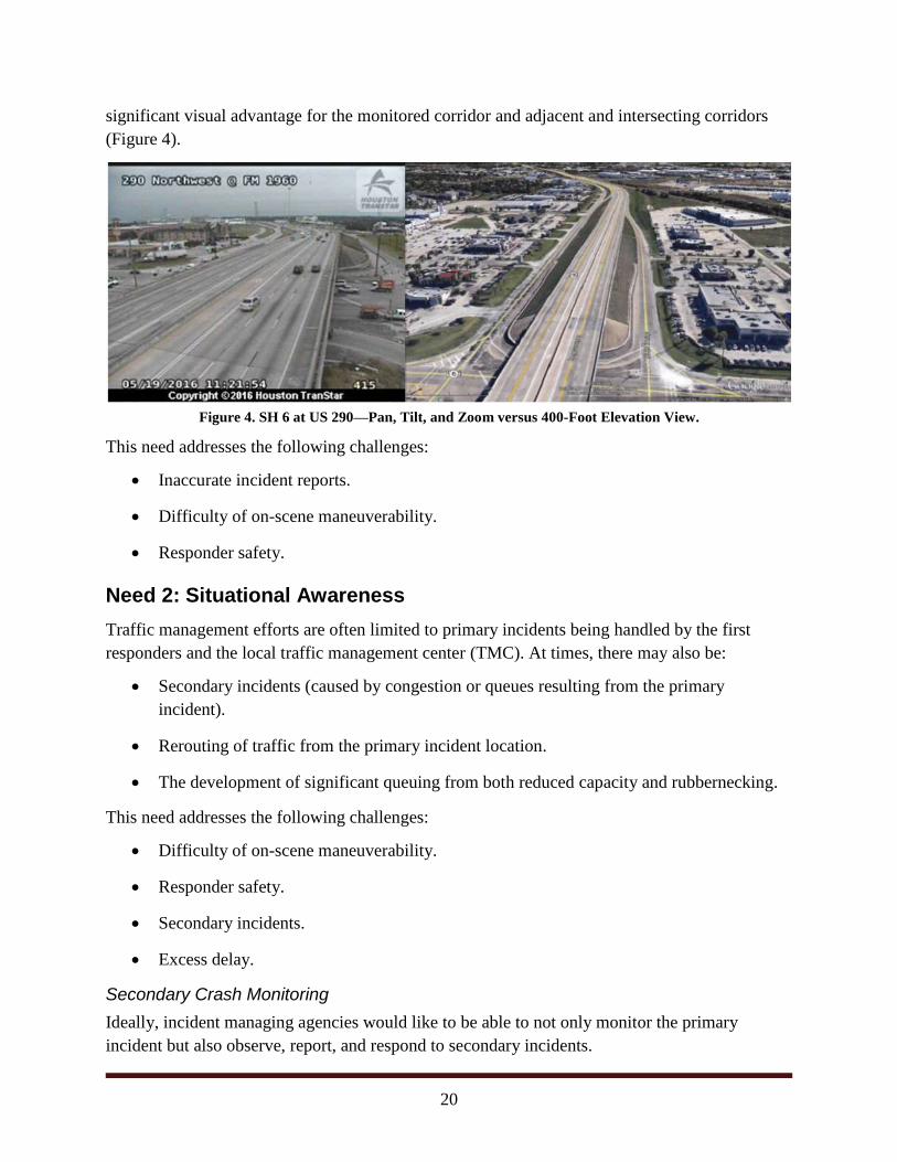
20
significant visual advantage for the monitored corridor and adjacent and intersecting corridors
(Figure 4).
Figure 4. SH 6 at US 290—Pan, Tilt, and Zoom versus 400-Foot Elevation View.
This need addresses the following challenges:
Inaccurate incident reports.
Difficulty of on-scene maneuverability.
Responder safety.
Need 2: Situational Awareness
Traffic management efforts are often limited to primary incidents being handled by the first
responders and the local traffic management center (TMC). At times, there may also be:
Secondary incidents (caused by congestion or queues resulting from the primary
incident).
Rerouting of traffic from the primary incident location.
The development of significant queuing from both reduced capacity and rubbernecking.
This need addresses the following challenges:
Difficulty of on-scene maneuverability.
Responder safety.
Secondary incidents.
Excess delay.
Secondary Crash Monitoring
Ideally, incident managing agencies would like to be able to not only monitor the primary
incident but also observe, report, and respond to secondary incidents.

21
Multiple Route Monitoring (Previously Unmonitored)
Prior to significant rerouting/diversion of traffic, agencies would like to be able to check that a
diversion route is feasible (especially a route of significant distance and/or drop-in functional
classification—for example, from an access-controlled freeway to an urban multilane highway).
Checking the diversion route would examine any existing closures due to construction, other
traffic incidents, and events along the diversion route. Monitoring would also provide the
opportunity to coordinate with local agencies to prepare for an increase in traffic through their
jurisdiction.
Traffic Queue Monitoring
Often significant queuing occurs as a result of the primary incident. Ideally, the management of
the primary incident would also include the ability to predict, observe, and confirm the
development of queues as a result of the incident. Existing established systems include
significant data collection and the use of algorithms to predict the end of queues. However, if
agencies could obtain real-time information by placing a cursor that moves with the end of the
queue, agencies could use this real-time queuing information for decision making and alternate
routing.
Need 3: Quick Clearance and Recovery
The longer an incident remains on the freeway system, the longer the queues, higher the delays,
and higher the chances for secondary crashes. The concept of quick clearance involves the
reduction in the time to detect, confirm, and clear an incident. Recovery includes monitoring the
incident scene and investigating fatal crashes.
This need addresses the following challenges:
Excess delay.
Lengthy minor incident clearance.
Lengthy major incident clearance.
Incident Detection and Confirmation
Agencies identify and confirm all incidents manually with the assistance of fixed cameras, and
use automated warnings for significant drops in speeds. Additional incident detection technology
and flexibility can greatly reduce the time necessary to identify and confirm incidents. This is
especially true for traffic incidents near difficult terrain or as a result of natural events.
Monitoring of Incident Scene
Issues related to the ability to clear an incident, including roadside conditions, bodies of water,
and large grade differentials, can increase delays, especially if unknown by responders.
Additional flexibility to survey roadside conditions may positively impact clearance times.

22
Fatal Crash Investigation
Fatal crashes and the corresponding investigation can cause significant delays including full
roadway closures. A certification of death by a medical examiner is usually required before
bodies are moved and the scene can be cleared. Additionally, documentation of the scene is
required, and the quicker investigators can complete this documentation, the sooner emergency
officials can clear the scene.
Researchers believe that service providers can attach sensor technologies as a payload to the
UAS to provide three-dimensional imaging and—in combination with HD photogrammetry—
provide a record of the crash scene.

23
Concept of Operations
UAS-TIM is a deployable tool that provides safe and enhanced monitoring capability and
payload flexibility for a variety of potential applications including traffic monitoring and crash-
scene mapping and photogrammetry. Agencies can use these UAS capabilities to meet the TIM
needs of situational awareness, incident monitoring (incident command participation), and quick
clearance.
UAS-TIM Goals
Agencies can deploy TIM-UAS to meet a variety of potential operational and TIM objectives.
States would most likely deploy UAS-TIM to:
Reduce non-recurring congestion by reducing incident clearance times.
Improve incident responder safety by providing enhanced images and video to the
incident command center.
Improve incident responder safety by removing staff members from unsafe incidents such
as chemical spills and incidents involving bodies of water and large grade differentials.
Improve real-time incident monitoring capabilities through capturing video and images at
higher elevations (within FAA regulations), using a mobile platform and innovative
sensor payloads (e.g., infrared).
Improve real-time monitoring capabilities of resulting queues, alternative routes, and
secondary crashes due to incidents through capturing video and images at higher
elevations (within FAA regulations) and using a mobile platform.
Reduce fatal crash clearance times by reducing the amount of time needed to map and
document crash scenes.
Components
Many components are required to support UAS-TIM functionality. The minimum requirements
include:
UAS—the vehicle or system that carries imaging and sensor payloads that will be flying
near or over live traffic. The UAS is assumed to have onboard navigational equipment.
Digital imaging payload—the HD camera attached to the UAS.
Various sensor payloads—infrared, LIDAR, etc.
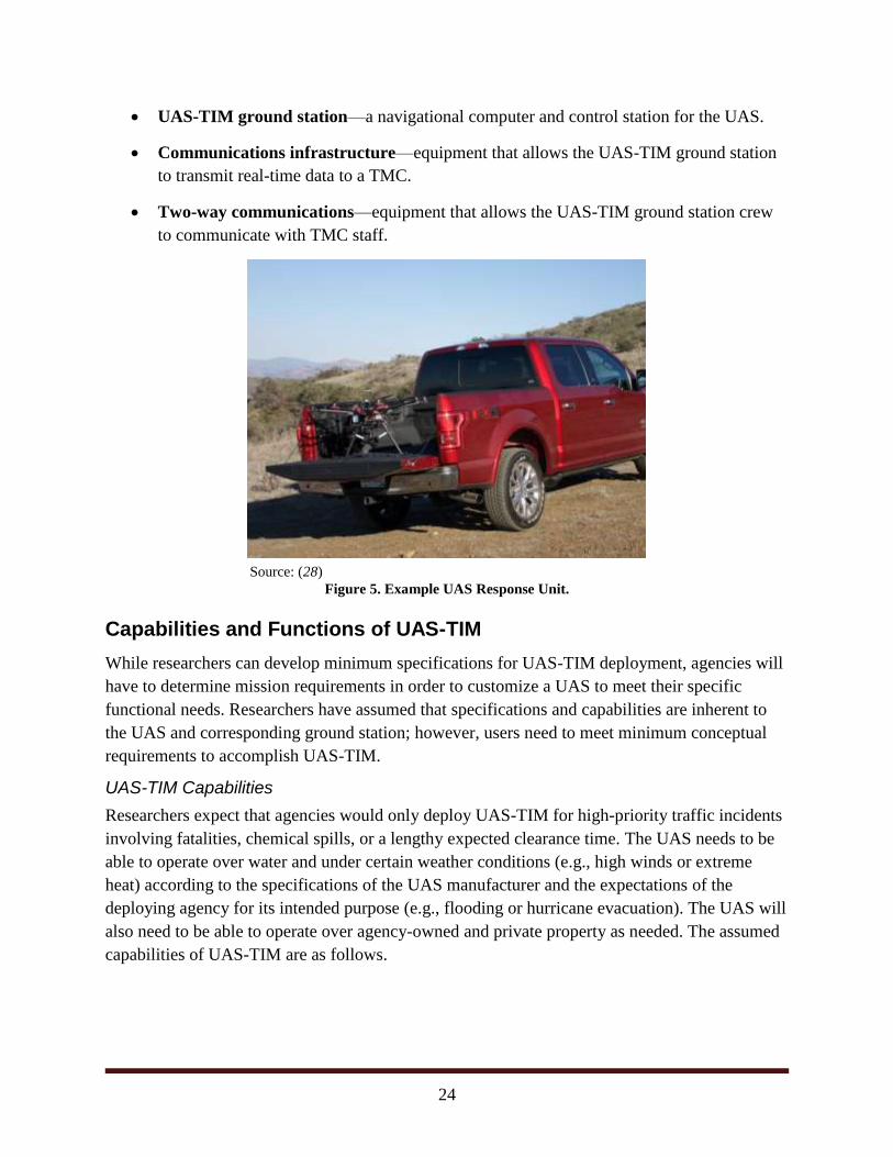
UAS-TIM response unit—a vehicle (probably a truck) to respond and deploy a UAS
(Figure 5).
24
UAS-TIM ground station—a navigational computer and control station for the UAS.
Communications infrastructure—equipment that allows the UAS-TIM ground station
to transmit real-time data to a TMC.
Two-way communications—equipment that allows the UAS-TIM ground station crew
to communicate with TMC staff.
Source: (28)
Figure 5. Example UAS Response Unit.
Capabilities and Functions of UAS-TIM
While researchers can develop minimum specifications for UAS-TIM deployment, agencies will
have to determine mission requirements in order to customize a UAS to meet their specific
functional needs. Researchers have assumed that specifications and capabilities are inherent to
the UAS and corresponding ground station; however, users need to meet minimum conceptual
requirements to accomplish UAS-TIM.
UAS-TIM Capabilities
Researchers expect that agencies would only deploy UAS-TIM for high-priority traffic incidents
involving fatalities, chemical spills, or a lengthy expected clearance time. The UAS needs to be
able to operate over water and under certain weather conditions (e.g., high winds or extreme
heat) according to the specifications of the UAS manufacturer and the expectations of the
deploying agency for its intended purpose (e.g., flooding or hurricane evacuation). The UAS will
also need to be able to operate over agency-owned and private property as needed. The assumed
capabilities of UAS-TIM are as follows.

25
Real-Time Enhanced Video and Photography
The UAS should be able to capture and deliver HD video and photography from within the
airspace and elevations as allowed by FAA regulations and approximately 400 feet above the
grade of the lowest agency-owned facility near a traffic incident. The UAS should be able to
effectively communicate with a central command center as needed.
Real-Time Non-video Sensor Data
The UAS should be able to capture sensor data (e.g., infrared for heat signature, motion, and
electronic signals) from within the airspace and elevations as approved by FAA regulations. The
UAS should be able to effectively communicate with a central command center and deliver
sensor data as needed.
Real-Time Payload (Cameras and Sensors) Mobility
The UAS should be mobile and have the ability to collect video, photography, and sensor data
while moving within the airspace and elevations as approved by FAA regulations. The UAS
should be able to effectively communicate with a central command center and deliver video,
photography, and sensor data as needed.
Communication of Data to a Traffic Incident Command Center
The UAS should be able to effectively communicate with a central command center and deliver
video, photography, and sensor data as needed. The UAS should use secure information
channels, and researchers expect it to first communicate with a ground station and then
effectively communicate in real time from the ground station to a central command.
Guided Mobile Data Collection
The UAS should be able to be guided by a pre-programmed flight plan (for global positioning
system and elevation waypoints) and collect video, photography, and sensor data while moving
within the airspace and elevations as approved by FAA regulations.
Photogrammetry and Mapping
The UAS should be able to provide accurate navigational data and photography as required to
meet the agency minimum requirements needed for legal proceedings resulting from a fatal
crash.
Safe Flight Operation near or over Live Traffic
The UAS should be able to operate safely near and over live traffic within the airspace and
elevations as approved by FAA regulations.
UAS-TIM Functions
Agencies can customize and deploy UAS-TIM to support a wide variety of incident management
functions. At a minimum, UAS-TIM must support the following functionality.

26
Real-Time Confirmation of a Traffic Incident
UAS-TIM should provide the information necessary to confirm the severity and extent of a
traffic incident.
Real-Time Monitoring of a Traffic Incident
UAS-TIM should provide enhanced real-time video, photography, and sensor data monitoring
functionality (to existing static cameras).
Real-Time Monitoring of Alternate Routes
UAS-TIM should provide real-time video, photography, and sensor data of alternate routes that
agencies can use for traffic diversion decision making.
Real-Time Monitoring of Traffic Incident Queuing
UAS-TIM should provide real-time video, photography, and sensor data of traffic queuing as a
result of the traffic incident.
Real-Time Monitoring of Secondary Crashes
UAS-TIM should provide real-time video, photography, and sensor data of secondary crashes
and incidents to aid in response.
Fatal Crash Scene Mapping
UAS-TIM should quickly provide sensor data (e.g., photogrammetry and LIDAR) that exceeds
the capabilities of manual crash scene mapping, with the aim to reduce the clearance time of the
incident.
Expanded UAS-TIM Functionality
During a meeting with potential implementers, researchers discovered that UAS-TIM could also
serve in an expanded capacity. UAS-TIM could provide video that agencies can use for incident
management training purposes.
Operational Scenarios
Researchers created five operational scenarios that explore possible operational responses to
incidents. TTI developed the scenarios in response to the determined TIM needs and variation of
incident response possibilities. The scenarios become useful to aid in planning and determining
the expected payloads of UAS.
Operational Scenario 1: Incident Monitoring
Agencies could use the incident monitoring scenario to monitor incidents where cameras are not
readily available or do not have the ability to pan, tilt, or zoom. Agencies could also use this
scenario simply for the added mobility of the camera for monitoring purposes. Figure 6
illustrates a potential layout of a basic UAS-TIM incident monitoring operational scenario.

27
Figure 6. Operational Scenario 1: Incident Monitoring.
The steps involved in this operational scenario include:
1. The TMC receives traffic incident information.
2. Based on agency UAS-TIM deployment protocols (type, extent, severity, etc.), the
TMC/command center deploys a UAS-TIM response unit to the scene.
3. The UAS-TIM response unit arrives at the traffic incident scene and positions itself on a
frontage road or private parking lot (Option A) or positions itself behind first responders
(Option B).
4. The UAS-TIM response unit launches a UAS with digital imaging payload.
5. The UAS-TIM digital imaging payload communicates with the UAS-TIM ground station,
transmitting real-time HD video.
6. The UAS-TIM ground station transmits HD video to the TMC.
7. The UAS-TIM ground station crew communicates with TMC staff to adjust video (pan,
tilt, and zoom) and/or UAS position. If possible, the ground station may give camera
control to the TMC, but UAS control always remains with the UAS-TIM ground station.
8. Depending on the battery life (for untethered UAS) of the UAS-TIM, operators bring the
UAS back to the UAS-TIM response unit for battery exchange and relaunch. The
response unit may consider multiple UAS for improved transition.
9. The UAS-TIM follows responder protocols before departing from the traffic incident
scene primarily based on instructions from the TMC.
-
-
-
-
28
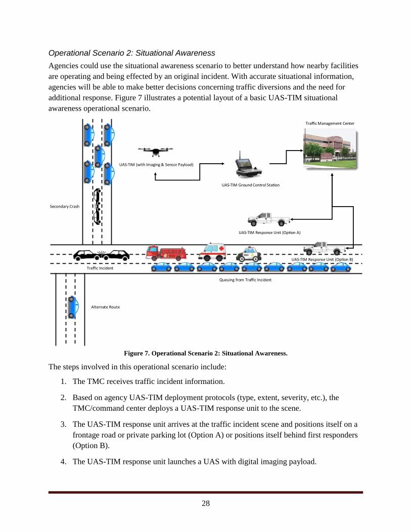
Operational Scenario 2: Situational Awareness
Agencies could use the situational awareness scenario to better understand how nearby facilities
are operating and being effected by an original incident. With accurate situational information,
agencies will be able to make better decisions concerning traffic diversions and the need for
additional response. Figure 7 illustrates a potential layout of a basic UAS-TIM situational
awareness operational scenario.
Figure 7. Operational Scenario 2: Situational Awareness.
The steps involved in this operational scenario include:
1. The TMC receives traffic incident information.
2. Based on agency UAS-TIM deployment protocols (type, extent, severity, etc.), the
TMC/command center deploys a UAS-TIM response unit to the scene.
3. The UAS-TIM response unit arrives at the traffic incident scene and positions itself on a
frontage road or private parking lot (Option A) or positions itself behind first responders
(Option B).
4. The UAS-TIM response unit launches a UAS with digital imaging payload.
-
-
-
-

29
5. The UAS-TIM digital imaging payload communicates with the UAS-TIM ground station,
transmitting real-time HD video.
6. The UAS-TIM ground station transmits HD video to the TMC.
7. The UAS-TIM ground station crew communicates with TMC staff to adjust video (pan,
tilt, and zoom) and/or UAS position. If possible, the ground station may give camera
control to the TMC, but UAS control always remains with the UAS-TIM ground station.
8. The UAS-TIM ground station crew communicates with TMC staff to adjust video (pan,
tilt, and zoom) and/or UAS position to monitor secondary crashes, queuing, and
alternative routes.
9. Depending on the battery life (for untethered UAS) of the UAS-TIM, operators bring the
UAS back to the UAS-TIM response unit for battery exchange and relaunch. The
response unit may consider multiple UAS for improved transition.
10. The UAS-TIM follows responder protocols before departing from the traffic incident
scene primarily based on instructions from the TMC.
Operational Scenario 3: Difficult Terrain, Safety, or Maneuverability
Agencies could use the difficult terrain, safety, or maneuverability scenario when an incident
takes place near areas of hazards or difficult terrain. Figure 8 illustrates a potential layout of a
UAS-TIM response for an incident with difficult terrain, safety concerns, or maneuverability
issues.

30
Figure 8. Operational Scenario 3: Difficult Terrain, Safety, or Maneuverability.
The steps involved in this operational scenario include:
1. The TMC receives traffic incident information.
2. Based on agency UAS-TIM deployment protocols (type, extent, severity, etc.), the
TMC/command center deploys a UAS-TIM response unit to the scene.
3. The UAS-TIM response unit arrives at the traffic incident scene and positions itself on a
frontage road or private parking lot (Option A) or positions itself behind first responders
(Option B).
4. The UAS-TIM response unit launches a UAS with digital imaging payload.
5. The UAS-TIM digital imaging payload communicates with the UAS-TIM ground station,
transmitting real-time HD video.
6. The UAS-TIM ground station transmits HD video to the TMC.
7. The UAS-TIM ground station crew communicates with TMC staff to adjust video (pan,
tilt, and zoom) and UAS position. If possible, the ground station may give camera control
to the TMC, but UAS control always remains with the UAS-TIM ground station.
8. The UAS-TIM ground station crew communicates with TMC staff to adjust video (pan,
tilt, and zoom) and UAS position to investigate, confirm, and monitor an incident taking
-
-
-
-
–

31
place in or on difficult terrain (e.g., bodies of water, steep grades, or elevation changes),
to address safety concerns (e.g., chemical spills), or to improve maneuverability.
9. Depending on the battery life (for untethered UAS) of the UAS-TIM, operators bring the
UAS back to the UAS-TIM response unit for battery exchange and relaunch. The
response unit may consider multiple UAS for improved transition.
10. The UAS-TIM follows responder protocols before departing from the traffic incident
scene primarily based on instructions from the TMC.
Operational Scenario 4: Natural Event
Agencies could use the natural event scenario during flooding and natural disasters such as after
a hurricane. Figure 9 illustrates a potential layout of a UAS-TIM response to an incident
occurring from a natural event.
Figure 9. Operational Scenario 4: Natural Event.
The steps involved in this operational scenario include:
1. The TMC receives traffic incident information.
2. Based on agency UAS-TIM deployment protocols (type, extent, severity, etc.), the
TMC/command center deploys a UAS-TIM response unit to the scene.
3. The UAS-TIM response unit arrives at the traffic incident scene and positions itself on a
frontage road or private parking lot (Option A) or positions itself behind first responders
(Option B).
4. The UAS-TIM response unit launches a UAS with digital imaging payload.
-
-
-
-
–

32
5. The UAS-TIM digital imaging payload communicates with the UAS-TIM ground station,
transmitting real-time HD video.
6. The UAS-TIM ground station transmits HD video to the TMC.
7. The UAS-TIM ground station crew communicates with TMC staff to adjust video (pan,
tilt, and zoom) and UAS position. If possible, the ground station may give camera control
to the TMC, but UAS control always remains with the UAS-TIM ground station.
8. The UAS-TIM ground station crew communicates with TMC staff to adjust video (pan,
tilt, and zoom) and UAS position to investigate, confirm, and monitor incidents taking
place during natural events such as flooding.
9. Depending on the battery life (for untethered UAS) of the UAS-TIM, operators bring the
UAS back to the UAS-TIM response unit for battery exchange and relaunch. The
response unit may consider multiple UAS for improved transition.
10. The UAS-TIM follows responder protocols before departing from the traffic incident
scene primarily based on instructions from the TMC.
Operational Scenario 5: Fatal Crash Scene Mapping
Agencies could use the fatal crash scene mapping scenario to help expedite the required
documentation of a fatal accident. Figure 10 illustrates a potential layout of the UAS-TIM
operational scenario involving crash scene mapping after a fatal crash.
Figure 10. Operational Scenario 5: Fatal Crash Scene Mapping.
-
-
-
-

33
The steps involved in this operational scenario include:
1. The TMC receives traffic incident information.
2. Based on agency UAS-TIM deployment protocols (type, extent, severity, etc.), the
TMC/command center deploys a UAS-TIM response unit to the scene.
3. The UAS-TIM response unit arrives at the traffic incident scene and positions itself on a
frontage road or private parking lot (Option A) or positions itself behind first responders
(Option B).
4. The UAS-TIM response unit launches a UAS with digital imaging payload.
5. The UAS-TIM digital imaging payload communicates with the UAS-TIM ground station,
transmitting real-time HD video.
6. The UAS-TIM ground station transmits HD video to the TMC.
7. The UAS-TIM ground station crew communicates with TMC staff to adjust video (pan,
tilt, and zoom) and/or UAS position. If possible, the ground station may give camera
control to the TMC, but UAS control always remains with the UAS-TIM ground station.
8. Depending on the battery life (for untethered UAS) of the UAS-TIM, operators bring the
UAS back to the UAS-TIM response unit for battery exchange and relaunch. The
response unit may consider multiple UAS for improved transition.
9. Steps 4–8 are repeated when Operational Scenario 5: Fatal Crash Scene Mapping follows
Operational Scenario 1: Incident Monitoring.
10. Upon receiving instruction from the TMC or first responders, the UAS-TIM adjusts
payload according to the desire mapping capabilities required by the local jurisdiction
(e.g., three-dimensional photogrammetry or LIDAR) and makes multiple passes along the
crash scene for mapping purposes.
11. The UAS-TIM ground control station downloads and verifies data capture and follows
responder protocols before departing from the traffic incident scene.
34
Architecture
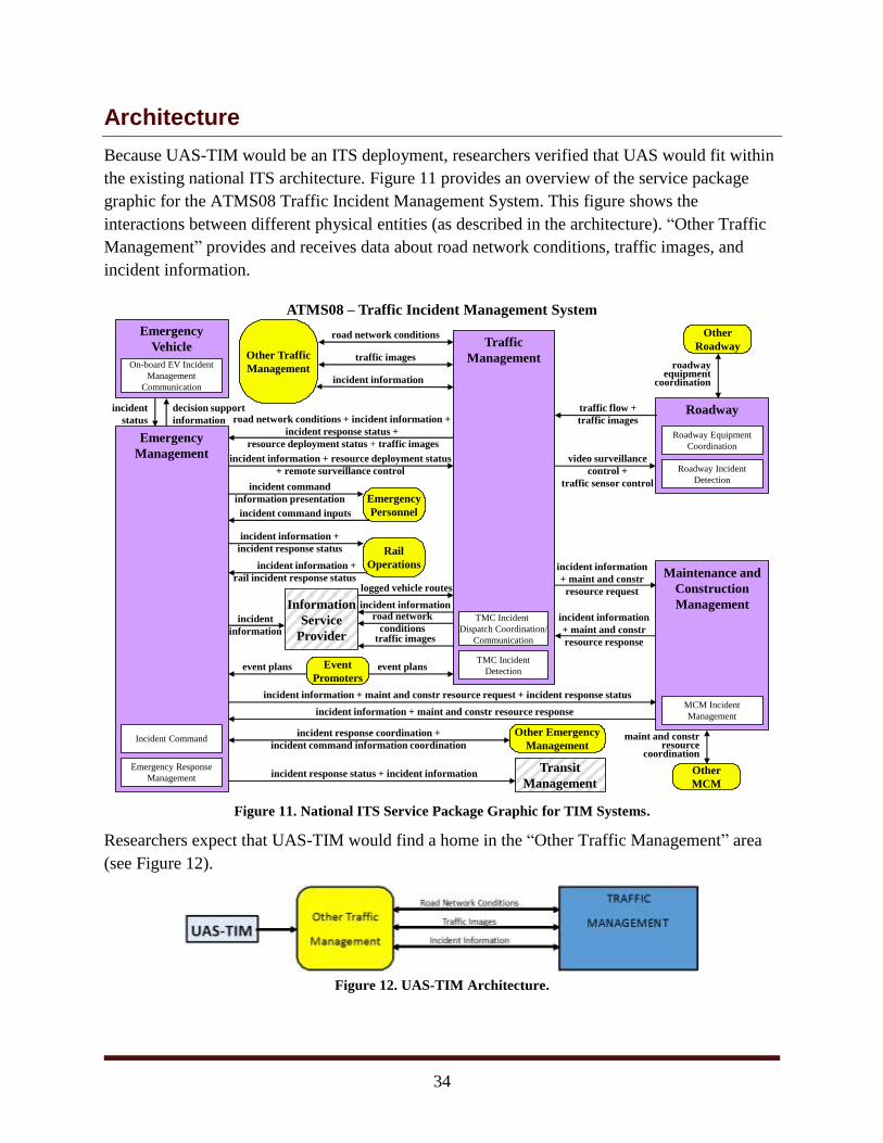
Because UAS-TIM would be an ITS deployment, researchers verified that UAS would fit within
the existing national ITS architecture. Figure 11 provides an overview of the service package
graphic for the ATMS08 Traffic Incident Management System. This figure shows the
interactions between different physical entities (as described in the architecture). “Other Traffic
Management” provides and receives data about road network conditions, traffic images, and
incident information.
Figure 11. National ITS Service Package Graphic for TIM Systems.
Researchers expect that UAS-TIM would find a home in the “Other Traffic Management” area
(see Figure 12).
Figure 12. UAS-TIM Architecture.
ATMS08 – Traffic Incident Management System
road network
conditions
Roadway
Traffic
Management
traffic flow +
traffic images
video surveillance
control +
traffic sensor control
incident information
+ maint and constr
resource response
Maintenance and
Construction
Management
Emergency
Management
incident
status
Other Emergency
Management
logged vehicle routes
incident
information
incident information + resource deployment status
+ remote surveillance control
road network conditions + incident information +
incident response status +
resource deployment status + traffic images
Roadway Incident
Detection
MCM Incident
Management
Emergency Response
Management
Information
Service
Provider
incident information
+ maint and constr
resource request
TMC Incident
Dispatch Coordination/
Communication
incident information + maint and constr resource request + incident response status
Roadway Equipment
Coordination
incident information + maint and constr resource response
Event
Promotersevent plans event plans
Other
MCM
maint and constrresource
coordination
Other
Roadway
TMC Incident
Detection
roadwayequipment
coordination
incident response coordination +
incident command information coordination
Emergency
Personnel
incident command
information presentation
Transit
Managementincident response status + incident information
incident information +
incident response status
incident information +
rail incident response status
Incident Command
Emergency
Vehicle
On-board EV Incident
Management
Communication
incident command inputs
decision support
information
incident information
Other Traffic
Management
road network conditions
incident information
traffic images
traffic images
Rail
Operations

35
Policy Considerations
Many regulations and policy considerations concern UAS-TIM. Most notable are the ever-
changing FAA rules and regulations. In addition to these federal rules, states have legislation
concerning when and where UAS can be flown and for what purposes. Policy also differs
depending on what type of organization is flying the UAS (e.g., test center, public agency, or
private company). On September 1, 2016, FAA published and made effective a new set of rules
and regulations (14 CFR Part 107). Researchers have only briefly reviewed these new policies at
the time of this report. However, researchers have added a separate task in Phase 2 for a
comprehensive review of 14 CFR Part 107. Additionally, in concern for public safety,
regulations can address operational safety considerations so that public agencies can understand
and identify who is best prepared to fly UAS safely and effectively.
FAA Rules and Regulations
FAA rules and regulations concerning UAS are constantly changing. Separate rules also apply to
public aircraft and civil (private) aircraft. FAA regulations address the process by which a UAS
can be safely operated in FAA airspace including operations, registration, maintenance,
inspection, visual line of sight, proximity to airports, and emergencies. As an exercise in
preparation for Phase 2, the Lone Star UAS Center of Excellence and Innovation provided flight
restriction maps for major urban centers in Texas, which are included as the Appendix.
Public Aircraft
FAA Advisory Circular 00-1.1A, Public Aircraft Operations, primarily governed FAA
regulations for public aircraft prior to the release of 14 CFR Part 107. With the release of
Part 107, public agencies (law enforcement, public universities, state governments, and local
governments) can operate UAS under two conditions, according to FAA (29):
1. Fly under the small UAS rule—follow all rules under 14 CFR part 107,
including aircraft and pilot requirements. The Aircraft must be used for civil
purposes.
OR
2. Obtain a Certificate of Waiver or Authorization (COA)—permits nationwide
flights in Class G airspace at or below 400 feet, or at a specific location and
altitude, self-certification of the UAS pilot, and the option to obtain
emergency, jurisdictional or special government interest COAs under special
circumstances.
Civil (Private) Aircraft
Previously governed by Section 333 Exemptions of the Modernizations and Reform Act of 2012,
civil UAS operators were required to apply and received a Section 333 exemption for
commercial (e.g., real estate or surveying) operations. FAA published Advisory Circular 107-2
on June 21 and replaced Section 333 effective September 1, 2016. The new rules and regulations

36
also created a remote pilot certification program, which is required to operate UAS in FAA
airspace.
Texas Laws and Legislation
Various state laws have bearing on UAS operations in Texas.
Texas House Bill 912
The following excerpts from House Bill (HB) 912 apply to UAS operations (30):
AN ACT relating to images captured by unmanned aircraft and other images and
recordings; providing penalties.
SECTION 1. This Act shall be known as the Texas Privacy Act.
Sec. 423.001. DEFINITION. In this chapter, “image” means any capturing of
sound waves, thermal, infrared, ultraviolet, visible light, or other electromagnetic
waves, odor, or other conditions existing on or about real property in this state or
an individual located on that property.
Sec. 423.002. NONAPPLICABILITY. (a) It is lawful to capture an image using
an unmanned aircraft in this state:
(1) for purposes of professional or scholarly research and development by a
person acting on behalf of an institution of higher education, as defined by
Section 61.003, Education Code, including a person who:
(A) is a professor, employee, or student of the institution; or
(B) is under contract with or otherwise acting under the direction or on behalf
of the institution;
(2) in airspace designated as a test site or range authorized by the Federal
Aviation Administration for the purpose of integrating unmanned aircraft systems
into the national airspace;
(8) if the image is captured by a law enforcement authority or a person who is
under contract with or otherwise acting under the direction or on behalf of a law
enforcement authority:
(C) for the purpose of investigating the scene of:
(i) a human fatality;
(ii) a motor vehicle accident causing death or serious bodily injury to a
person; or
(iii) any motor vehicle accident on a state highway or federal interstate or
highway;

37
(D) in connection with the search for a missing person;
(E) for the purpose of conducting a high-risk tactical operation that poses a
threat to human life; or
(F) of private property that is generally open to the public where the property
owner consents to law enforcement public safety responsibilities;
(9) if the image is captured by state or local law enforcement authorities, or a
person who is under contract with or otherwise acting under the direction or on
behalf of state authorities, for the purpose of:
(A) surveying the scene of a catastrophe or other damage to determine
whether a state of emergency should be declared;
(B) preserving public safety, protecting property, or surveying damage or
contamination during a lawfully declared state of emergency; or
(C) conducting routine air quality sampling and monitoring, as provided by
state or local law;
(10) at the scene of a spill, or a suspected spill, of hazardous materials;
(11) for the purpose of fire suppression;
(12) for the purpose of rescuing a person whose life or well-being is in imminent
danger;
Sec. 423.003. OFFENSE: ILLEGAL USE OF UNMANNED AIRCRAFT TO
CAPTURE IMAGE. (a) A person commits an offense if the person uses an
unmanned aircraft to capture an image of an individual or privately owned real
property in this state with the intent to conduct surveillance on the individual or
property captured in the image.
Texas House Bill 1481
The following excerpt from HB 1481 prohibits the operation of an unmanned aircraft over
certain facilities, creating a criminal offense (31):
Sec. 423.0045. OFFENSE: OPERATION OF UNMANNED AIRCRAFT OVER
CRITICAL INFRASTRUCTURE FACILITY.
This section does not apply to conduct described by Subsection (b) that is
committed by:
(1) the federal government, the state, or a governmental entity;
(2) a person under contract with or otherwise acting under the direction or on
behalf of the federal government, the state, or a governmental entity;
(3) a law enforcement agency;
38
(4) a person under contract with or otherwise acting under the direction or on
behalf of a law enforcement agency;
(5) an owner or operator of the critical infrastructure facility;
(6) a person under contract with or otherwise acting under the direction or on
behalf of an owner or operator of the critical infrastructure facility;
(7) a person who has the prior written consent of the owner or operator of the
critical infrastructure facility;
(8) the owner or occupant of the property on which the critical infrastructure
facility is located or a person who has the prior written consent of the owner or
occupant of that property; or
(9) an operator of an unmanned aircraft that is being used for a commercial
purpose, if the operator is authorized by the Federal Aviation Administration to
conduct operations over that airspace.
Texas House Bill 2167
HB 2167 relates to certain images captured by an unmanned aircraft. This bill amends HB 912
passed in the previous session by adding the following three additional items to the
“Nonapplicability” section (32):
a registered professional land surveyor in connection with the practice of
surveying…provided no individual is identifiable in the image
a licensed professional engineer…in connection with the practice of
engineering…provided no individual is identifiable in the image
a person acting on behalf of an institution of higher education or a private or
independent institution of higher education
Potential State Regulations for UAS Operations
With the development of FAA’s remote pilot certification program, potential UAS operators
must meet educational and testing requirements for civil UAS operation. Currently, FAA limits
UAS operation over people unless granted an exemption. When considering operating over live
traffic and/or the general public, it may be appropriate to consider additional third-party vetting
for operators to demonstrate to FAA that service providers can conduct these types of missions
safely and effectively.
One such program already exists in a partnership between the Texas A&M Engineering
Extension Service and the Lone Star UAS Center of Excellence and Innovation, a State of Texas
FAA UAS Test Site. These agencies have developed one of the first national UAS credentialing
programs. This program offers Section 333 exemption/CFR 14 Part 107 service providers the
opportunity to receive a third-party vetting, oral audit, and live-flight operational audit of all of

39
their operational and safety policies, procedures, and qualifications required by FAA. The
credentialing program offers multiple tracks including state and federal disaster response and
energy-sector activities. Researchers are not fully knowledgeable about the direct impact this
credentialing program has on the safety and effectiveness of UAS operations but will briefly
investigate the potential benefits in Phase 2 of the project.
Operating UAS over Private Property
When organizing the operational scenarios portion of this document, researchers used the
insights of a Houston-based Section 333 Exemption UAS service provider to determine
appropriate operational response scenarios. During these discussions, the service provider was
very cautious concerning the state laws requiring property owner permission to fly UAS. Their
primary concern was losing their nationwide exemption due to violation of state laws. The intent
of state laws concerning UAS needs to be supplemented and/or clarified.
This was also evident during a previous TxDOT-sponsored research project focused on access
management where the commercial UAS service provider requested a letter from TxDOT
granting it permission to fly over state right of way. The service provider made these requests
despite language in HB 912 concerning nonapplicability for scholarly research on behalf of a law
enforcement authority and/or for investigating the scene of a human fatality or motor vehicle
accident on a state highway.
In discussion for Phase 2 of this project, where researchers will potentially use service providers
to complete pilot demonstration missions, the same service provider has already indicated it
would again request a letter of permission to fly over public agency property. The service
provider was also not comfortable flying over private property adjacent to public right of way,
potentially limiting the usefulness of the application.

40
Findings and Next Steps
Findings
This research demonstrates that agencies could use UAS-TIM as an effective tool to help with
recurring congestion from traffic incidents. Researchers found significant research questions
about operating UAS over live traffic and people—even more so under real-time TIM
conditions.
Next Steps
To continue to learn about the capabilities and limitations of UAS-TIM, live demonstrations of
both the UAS and real-time communications are necessary to evaluate and determine the
effectiveness of the system and its potential to reduce congestion.
Evaluation Protocol
For a live demonstration, researchers must first establish a data collection and performance
measurement plan to compare typical incident management practices to demonstrations using
UAS-TIM. Understanding performance measures will allow researchers to evaluate and validate
UAS. Observations and discussions with responders and TMC staff will also provide insight into
the benefit of UAS-TIM.
Agency Participation
Researchers will coordinate with participating public agencies. Currently, the Metropolitan
Transit Authority of Harris County has verbally committed to the demonstration phase of the
project. Researchers are also working with the City of Corpus Christi and are beginning to
coordinate with the TxDOT Aviation Division to explore opportunities to demonstrate UAS
over/near TxDOT right of way. Advanced digital imaging technology may not necessarily
require the UAS to operate over public right of way at all. Some digital imaging payload and
stabilization technologies can allow for enhanced imaging miles away.
FAA Authorization and Safe Operation
Researchers must investigate the process of gaining authorization from FAA to fly over live
traffic and people and must better understand airspace restrictions. Additionally, the emerging
concept of additional vetting and credentialing needs to be studied to determine when and if they
are necessary for safe and effective UAS operation. Discussion with Texas A&M Engineering
Extension Service leadership revealed that the release of 14 CFR Part 107 may quickly increase
the number of commercial UAS service providers, primarily due to the relaxation of the rules
related to the qualifications of UAS pilots and not having to secure COAs.
In this first demonstration of UAS-TIM in Texas, agencies and researchers need to be confident
that operators have legal authorization to fly and can do so safely. TTI will require service
providers to meet every FAA regulation and legal requirement during flight missions. TTI will
41
only consider using service providers that have a safe operating record and credentials that
recognize safe and effective operation ability, such as from the National UAS Credentialing
Program. This vetting process brings a higher level of safety and standards to those individual
companies that public agencies may consider.
Selection of UAS Service Providers
TTI is considering different service providers to partner with, including using the tethered UAS
service provider that the National Operations Center of Excellence recently highlighted in a
nationwide webinar. Researchers expect that in addition to a private commercially exempt
service provider, TTI will explore partnering with the Lone Star UAS Center of Excellence and
Innovation, an FAA UAS Test Site. It is unknown what FAA will require for a commercial
service provider to fly over live traffic.
Partnering with an FAA UAS Test Site will allow greater flexibility if FAA restrictions prevent
successful civil UAS missions. The Lone Star UAS Center of Excellence and Innovation has
direct communications with FAA and has the authority to operate in the national airspace at
higher altitudes and under different conditions (e.g., nighttime missions) compared to Part 107
commercial service providers. Additionally, the use of an FAA UAS Test Site provides for a
greater safety management system than potentially a commercial service provider would possess
and provides mission feedback to FAA. However, the project still aims to investigate important
policy issues surrounding public and civil UAS operations.
Policy and Legal Impacts
There is a need to better understand the various Texas laws and federal regulations with respect
to the legality of UAS-TIM. This is especially true with state UAS property laws and the newly
implemented 14 CFR Part 107.
Continuing Research
The next phase of continuing research will include the following activities:
1. Develop a data collection plan.
2. Select and contract with a UAS service provider and/or FAA Test Site.
3. Complete a comprehensive review of 14 CFR Part 107.
4. Complete a legal review of HB 912 and HB 1481.
5. Conduct a UAS-TIM demonstration (over live traffic).
6. Evaluate the demonstration and prepare a formal report.

42
References
1. Federal Highway Administration Office of Operations. Operations Story. February 5,
2017. http://www.ops.fhwa.dot.gov/aboutus/opstory.htm.
2. Federal Highway Administration Office of Operations. Traffic Incident Management Gap
Analysis Primer. February 1, 2017.
http://ops.fhwa.dot.gov/publications/fhwahop15007/chapter1.htm.
3. Federal Highway Administration Office of Operations. Developing and Using a Concept
of Operations in Transportation Management Systems. August 2005.
https://tmcpfs.ops.fhwa.dot.gov/cfprojects/uploaded_files/conops_tms_handbook.pdf.
4. California Department of Transportation Division of Research, Innovation, and System
Information. The Use of Unmanned Aerial Systems for Steep Terrain Investigations.
August 14, 2014.
http://www.dot.ca.gov/research/researchreports/preliminary_investigations/docs/unmann
ed_aerial_systems_preliminary_investigation_rev8-14-14.pdf.
5. Carroll, E. A., and Rathbone, D. B. Using an Unmanned Airborne Data Acquisition
System (ADAS) for Traffic Surveillance, Monitoring, and Management. American Society
of Mechanical Engineers, 2002.
6. Pastor, J. D. Virginia Tech’s Unmanned Aircraft Test Site Program ‘Fully Operational,’
FAA Says. Office of University Relations, August 13, 2014.
7. Latchman, H. A., Wong, T., Shea, J., McNair, J., and Fang, M. Airborne Traffic
Surveillance Systems Proof of Concept Study. University of Florida and Florida
Department of Transportation, 2005.
8. Coifman, B., McCord, M., Mishalani, R., Iswalt, M., and Ji, Y. Roadway Traffic
Monitoring from an Unmanned Aerial Vehicle. Intelligent Transport Systems, IEEE,
2006, pp. 11–20.
9. Judson, F. The Ohio Department of Transportation and Unmanned Aircraft Systems.
Lidar Magazine, Vol. 3, No. 5, 2013.
10. Ohio/Indiana UAS Center. Website.
http://www.dot.state.oh.us/divisions/uas/Pages/default.aspx.
11. McCormack, E. D. The Use of Small Unmanned Aircraft by the Washington State
Department of Transportation. Washington State Department of Transportation, 2008.
12. Barfuss, S. L., Jensen, A., and Clemens, S. Evaluation and Development of Unmanned
Aircraft (UAV) for UDOT Needs. Utah Department of Transportation, 2012.
13. Irizarry, J., and Johnson, E. N. Feasibility Study to Determine the Economic and
Operational Benefits of Utilizing Unmanned Aerial Vehicles (UAVs). Report No.
FHWA-GA-1H-12-38. Georgia Institute of Technology for Georgia Department of
Transportation, April 2014.
14. Karpowicz, R. The Use of Unmanned Aerial Systems for Steep Terrain Investigations.
California Department of Transportation, August 2014.
43
15. Brooks, C., Dobson, R., Banach, D., Dean, D., Oommen, T., Wolf, R., Havens, T.,
Ahlborn, T., and Hart, B. Evaluating the Use of Unmanned Aerial Vehicles for
Transportation Purposes. Michigan Technological University for Michigan Department
of Transportation, March 2015.
16. Estes, C. Unmanned Aircraft in North Carolina—Report to the Joint Legislative
Oversight Committee on Information Technology and Transportation Oversight
Committee. March 2014.
17. Research and Innovative Technology Administration. Development of UAV-Based
Remote Sensing Capabilities for Highway Applications: UTC Spotlight. February 2012.
18. Abrahamsen, H. B. A Remotely Piloted Aircraft System in Major Incident Management:
Concept and Pilot, Feasibility Study. BMC Emergency Medicine, Vol. 15, No. 12, 2015.
19. Su, S., Liu, W., Li, K., Yang, G., Feng, C., Ming, J., Liu, G., Liu, S., and Yin, Z.
Developing an Unmanned Aerial Vehicle-Based Rapid Mapping System for Traffic
Accident Investigation. Australian Journal of Forensic Sciences, August 21, 2015.
http://www.tandfonline.com/doi/abs/10.1080/00450618.2015.1073787.
20. Toth, C., Brzezinska, G., and Merry, C. Supporting Traffic Flow Management with High
Definition Imagery. Proceedings of Joint ISPRS Workshop on High Resolution Mapping
from Space, Hannover, Germany, 2003.
21. Bethke, K.-H., Baumgartner, S., and Gabele, M. Airborne Road Traffic Monitoring with
Radar. World Congress on Intelligent Transport Systems (ITS), Neijing, China, 2007.
22. Kim, Z. W. Real-Time Road Detection by Learning from One Example. 7th IEEE
Workshops on Application of Computer Vision, Vol. 1, 2005.
23. Puri, A., Valavanis, K. P., and Kontitsis, M. Statistical Profile Generation for Traffic
Monitoring Using Real-Time UAV Based Video Data. IEEE Mediterranean Conference
on Control and Automation, Athens, Greece, 2007.
24. Gleason, J., Nefian, A. V., Bouyssounousse, X., Fong, T., and Bebis, G. Vehicle
Detection from Aerial Imagery. IEEE Intelligent Conference on Robotics and
Automation, 2011.
25. Chen, Y. M., Dong, L., and Oh, J.-S. Realtime Video Relay for UAV Traffic Surveillance
Systems through Available Communication Networks. IEEE Wireless Communications
and Networking Conference, 2007.
26. Coifman, B., McCord, M., Mishalani, R., Iswalt, M., and Ji, Y. Roadway Traffic
Monitoring from an Unmanned Aerial Vehicle. IEEE Proceedings of Intelligent
Transportation System, Vol. 153, No. 1, March 2006.
27. Federal Highway Administration Office of Operations. Best Practices in Traffic Incident
Management. September 2010.
https://ops.fhwa.dot.gov/publications/fhwahop10050/fhwahop10050.pdf.

44
28. Ford Motor Company. Ford Targets Drone-to-Vehicle Technology to Improve
Emergency Services, Commercial Business Efficiency. January 5, 2016.
https://media.ford.com/content/fordmedia/fna/us/en/news/2016/01/05/ford-targets-drone-
to-vehicle-technology.html.
29. Federal Aviation Administration. Beyond the Basics. August 29, 2016.
https://www.faa.gov/uas/beyond_the_basics/.
30. Texas House Bill 912.
http://www.legis.state.tx.us/tlodocs/83R/billtext/html/HB00912F.HTM.
31. Texas House Bill 1481.
http://www.legis.state.tx.us/tlodocs/84R/billtext/pdf/HB01481F.pdf.
32. Texas House Bill 2167.
http://www.capitol.state.tx.us/tlodocs/84R/billtext/pdf/HB02167F.pdf.

45
Appendix—Texas Urban Airspace Analyses
Figure 13. Austin Airspace Analysis.
Figure 14. College Station Airspace Analysis.

46
Figure 15. Dallas-Fort Worth Airspace Analysis.
Figure 16. El Paso Airspace Analysis.

47
Figure 17. Houston Airspace Analysis.
Figure 18. Rio Grande Valley Airspace Analysis.

48
Figure 19. San Antonio Airspace Analysis.