Embed Size (px)
Citation preview

MCAO Conceptual Design Documentation Rev 1.0, 05/15/00
Conceptual Design Review Documents
MCAO for Gemini-South
Gemini Observatory May 30-31, 2000

MCAO
MCAO Conceptual Design Documentation 2 Rev 1.0, 05/15/00

MCAO
MCAO Conceptual Design Documentation i Rev 1.0, 05/15/00
TABLE OF CONTENTS MCAO Acronyms…………………………………………………………………...v
1 Project Overview....................................................................................................... 1
1.1 The MCAO Project ............................................................................................. 1 1.2 The Project Team................................................................................................ 1 1.3 The Conceptual Design Review.......................................................................... 2 1.4 The Conceptual Design Documentation............................................................. 2 1.5 Project Background ............................................................................................. 2 1.6 Project Progress................................................................................................... 3 1.7 Project Plans ........................................................................................................ 5 1.8 Science Instruments for MCAO.......................................................................... 6
2 The MCAO Science Case.......................................................................................... 7
2.1 Context ................................................................................................................ 7 2.2 MCAO versus AO............................................................................................... 8
2.2.1 Need for lasers ................................................................................................ 8 2.2.2 MCAO Sensitivities ........................................................................................ 8 2.2.3 Sky coverage ................................................................................................... 8 2.2.4 Multiplex gain ............................................................................................... 10 2.2.5 Uniform PSF ................................................................................................. 11
2.2.5.1 On altitude conjugation............................................................................. 11 2.3 MCAO and the Gemini Science program......................................................... 11 2.4 MCAO in the NGST Era................................................................................... 14
2.4.1 Gemini MCAO and NGST DRM programs ................................................. 15 2.5 The science requirements.................................................................................. 22
3 System Overview...................................................................................................... 25
3.1 Primary Subsystems and Their Characteristics................................................. 25 3.2 System Performance ......................................................................................... 27
3.2.1 Image Quality................................................................................................ 27 3.2.2 Science Path Throughput and Emissivity ..................................................... 29
4 System Modeling ...................................................................................................... 31
4.1 Goals and Tools ................................................................................................ 31 4.2 Background ....................................................................................................... 32
4.2.1 Cerro Pachon Site Characterization Summary ............................................. 32 4.2.2 The Need for Multiple Tip-Tilt Natural Guide Stars .................................... 33 4.2.3 Scintillation Effects and the Ordering of Deformable Mirrors ..................... 34
4.3 Optimization and Trade Studies........................................................................ 35 4.3.1 Order of Sensing and Correction .................................................................. 35 4.3.2 Deformable Mirror Conjugate Ranges.......................................................... 36 4.3.3 Corrected Field-of-View............................................................................... 36 4.3.4 LGS Signal Level and Control Bandwidth................................................... 37

MCAO
MCAO Conceptual Design Documentation ii Rev 1.0, 05/15/00
4.4 Natural Guide Star Modeling ............................................................................ 41 4.4.1 Decoupling the LGS and NGS Control Loops ............................................. 41 4.4.2 NGS Magnitude Limits ................................................................................. 43 4.4.3 PSF Characteristics ....................................................................................... 45
4.4.3.1 Telescope and instrument .......................................................................... 47 4.4.4 Sky Coverage ................................................................................................ 47
4.5 Summary........................................................................................................... 49
5 Subsystem Design..................................................................................................... 51
5.1 Adaptive Optics Module ................................................................................... 51 5.1.1 Optical Design............................................................................................... 51
5.1.1.1 Design Requirements ................................................................................ 52 5.1.1.2 Science Path.............................................................................................. 52 5.1.1.3 LGS Path and Field Corrector................................................................... 54 5.1.1.4 LGS collimator and “De-Anamorphoser”................................................. 56 5.1.1.5 NGS WFS Path and NGS/LGS Beamsplitter ........................................... 58 5.1.1.6 Transmittance Calculations....................................................................... 59 5.1.1.7 Fabricability .............................................................................................. 60
5.1.2 Sensors .......................................................................................................... 61 5.1.2.1 LGS Wave Front Sensor ........................................................................... 62 5.1.2.2 NGS Tip/Tilt Wave Front Sensor ............................................................. 63 5.1.2.3 NGS Diagnostic Higher-Order Wave Front Sensor.................................. 64
5.1.3 Deformable and Tip/Tilt Mirrors .................................................................. 64 5.1.4 Artificial Sources .......................................................................................... 66 5.1.5 Mechanical Packaging Concepts .................................................................. 66
5.2 Laser System..................................................................................................... 69 5.2.1 Requirements ................................................................................................ 69
5.2.1.1 Laser power requirement .......................................................................... 69 5.2.1.2 Other top- level requirements .................................................................... 71
5.2.2 Technology Options ...................................................................................... 72 5.2.3 Development Plan......................................................................................... 73
5.3 Laser Launch Telescope (LLT) and Beam Transfer Optics (BTO).................. 74 5.3.1 Requirements ................................................................................................ 74 5.3.2 Design Overview........................................................................................... 75 5.3.3 Laser Launch Telescope................................................................................ 77
5.3.3.1 Optical Design........................................................................................... 77 5.3.3.2 Mechanical Design.................................................................................... 78
5.3.4 Beam Transfer Optics ................................................................................... 81 5.3.4.1 Laser path.................................................................................................. 81 5.3.4.2 Diagnostics................................................................................................ 82 5.3.4.3 Other Components .................................................................................... 83
5.4 The MCAO Control System ............................................................................. 85 5.4.1 Overview....................................................................................................... 85 5.4.2 The MCAO Sequencer.................................................................................. 86 5.4.3 The Component Controller and the Laser Controller ................................... 87 5.4.4 The Real Time Controller ............................................................................. 97
5.4.4.1 Main requirements .................................................................................... 97

MCAO
MCAO Conceptual Design Documentation iii Rev 1.0, 05/15/00
5.4.4.2 NGS Requirements and Algorithm Description ....................................... 99 5.4.4.3 LGS Requirements and Algorithm Description...................................... 100 5.4.4.4 Optimization and Background Processes................................................ 101 5.4.4.5 Calibration Processes .............................................................................. 104 5.4.4.6 Diagnostics.............................................................................................. 105 5.4.4.7 Hardware Options and Baseline Approach............................................. 105
5.4.5 VME Hardware Requirements.................................................................... 109 5.4.6 Power Requirements ................................................................................... 110
5.5 Safe Aircraft Localization and Satellite Acquisition system (SALSA) .......... 110
6 Commissioning, Calibration, and Concept of Operations ................................. 113
6.1 Commissioning tasks ...................................................................................... 113 6.2 Instrument setup .............................................................................................. 113 6.3 Concept of operations ..................................................................................... 114
6.3.1 Technical operations ................................................................................... 114 6.3.2 Science operations/modes........................................................................... 114
6.4 Operational overheads..................................................................................... 115
7 Interface Summary ................................................................................................ 117
7.1 Instrument Support Structure (ISS) ................................................................ 117 7.1.1 Mechanical.................................................................................................. 117 7.1.2 Services ....................................................................................................... 117 7.1.3 Handling...................................................................................................... 117
7.2 Secondary Support Structure interface ........................................................... 118 7.2.1 Mechanical interface ................................................................................... 118 7.2.2 Services ....................................................................................................... 118
7.2.2.1 Electrical ................................................................................................. 118 7.2.2.2 Coolant .................................................................................................... 118
7.3 Control System Interfaces ............................................................................... 118 7.3.1 Telescope Control System (TCS) ............................................................... 118 7.3.2 Acquisition and Guiding System (A&G).................................................... 119
Appendices:
A. MCAO Science Case B. MCAO Functional and Performance Requirements Document C. MCAO Operational Concept Definition Document D. LGS AO and MCAO Performance as a Function of LGS Signal Level E. Evaluating and Optimizing Control Algorithms for Combined LGS/NGS MCAO
Systems F. Compensation of the Null Modes with the Gemini MCAO G. Secondary Support Structure Interface H. MCAO Beam Transfer Optics Requirements Document I. Laser Launch Telescope Requirements Document J. Beam Transfer Optics and Laser Launch Telescope Design Document K. Electronics, Sensors & Actuators in the Beam Transfer Optics

MCAO
MCAO Conceptual Design Documentation iv Rev 1.0, 05/15/00
L. LGS AO Photon Return Simulations and Laser Requirements for the Gemini LGS AO Program
M. Laser Requirements and Prospects for the Gemini LGS AO Program N. Durham MCAO Lab Demo Status
Drawings:
Beam Transfer Optics conceptual design for a single beam (LLT1PLAN.DWG) Beam Transfer Optics conceptual design for a five beam array
(LLT5PLAN.DWG) Deployment concept for the LLT primary mirror (DEPLOY.DWG) Concept to optimize repeatability of LLT primary mirror deployment
(LLT_MC1.DWG and LLT_MC2.DWG) Secondary Support Structure to LLT mounting interface (SSS.DWG) Conceptual view of the BTO beam path (HROSPATH.DWG) Beam Transfer Optics along the –X +Y top end vane (VANEPATH.DWG)

MCAO
MCAO Conceptual Design Documentation v Rev 1.0, 05/15/00
MCAO Acronyms ADC Atmospheric Dispersion Corrector ADC Analog-to-Digital Converter AO Adaptive Optics AOM Adaptive Optics Module APD Avalanche Photo Diode BS Beam Splitter BTO Beam Transfer Optics CAD Command Action Directive Record CB Circular Buffer CC Component Controller CC Corner Cube CCD Charged Coupled Devices CDR Critical Design Review CoDR Conceptual Design Review CP Cerro Pachon CPU Central Processing Unit CW Continuous Wave (laser) DAC Digital-to-Analogue Converter DHS Data Handling System DM Deformable Mirror DRM Design Reference Mission EPICS Experimental Physics and Industrial Control System ESO European Southern Observatory FWHM Full Width at Half Maximum GIS Gemini Interlock System GRB Gamma Ray Burster GSC Gemini Science Committee GSM Generalized Seeing Monitor HROS High Resolution Optical Spectrograph HRWFS High Resolution Wave Front Sensor ICS Instrument Control Sequencer IGPO International Gemini Project Office IOC Input/Output Controller IRMOS Infra-Red Multi-Object Spectrograph IS Instrument Sequencer ISS Instrument Support Structure LAN Local Area Network LC Laser Component LS Laser System LEM Laser Electronics Module LGS Laser Guide Star LGS CS Laser Guide Star Control System LLT Laser Launch Telescope mas Milli arc second

MCAO
MCAO Conceptual Design Documentation vi Rev 1.0, 05/15/00
MCAO Multi-Conjugate Adaptive Optics MCAO CS MCAO Control System MK Mauna Kea MK LGS AO Mauna Kea Laser Guide Star Adaptive Optics M2TS Secondary Mirror Tilt System NGS Natural Guide Star NGST Next Generation Space Telescope NIR Near Infra Red NPO National Project Office OAP Off-Axis Parabola OCDD Operational Concepts Definition Document OCS Observatory Control System OIWFS On Instrument Wavefront Sensor OPO Optical Parametric Oscillator OTF Optical Transfer Function QLT Quick Look Tool PDR Preliminary Design Review PIO Parallel Input Output PMC PCI Mezzanine Card PSD Power Spectral Density PSD Position Sensing Detector PSF Point Spread Function PZT Piezoelectric Translator RFP Request For Proposals RMS Root Mean Square RTC Real Time Component SAD Status Alarm Database SALSA Safe Aircraft Localization and Satellite Acquisition System SC Sky Coverage SCS Secondary Control System SFG Sum-Frequency Generation SH Shack-Hartmann SHG Second Harmonic Generation SIR Status Information Record SSS Secondary Support Structure TCS Telescope Control System TT Tip/Tilt TTM Tip-Tilt Mirror VME Versa Module Europa – a Eurocard-based bus system WFS Wave Front Sensor Flops Number of floating point operation per second. A multiply/add
corresponds to 2 operations. VxWorks A real time operating system

MCAO
MCAO Conceptual Design Documentation 1 Rev 1.0, 05/15/00
1 PROJECT OVERVIEW 1.1 The MCAO Project
The Gemini Multi-Conjugate Adaptive Optics (MCAO) system is a proposed facility instrument for the Gemini-South telescope that is intended to provide uniform, diffraction-limited image quality at near IR wavelengths across an extended field-of-view. This will yield increases in scientific utility and observational efficiency well beyond what is feasible with a conventional AO system, and provide unique capabilities for Gemini-South in the 2004-9 time frame. For a range of criteria, mean performance over a one square arc minute field-of-view will be comparable to the on-axis performance of the Altair laser guide star (LGS) AO system for Gemini-North. Sky coverage will also comparable or somewhat superior. The MCAO system will largely eliminate the impact of anisoplanatism on AO performance by compensating atmospheric turbulence in three dimensions. This will be accomplished using multiple deformable mirrors (DM’s) conjugate to distinct ranges in the atmosphere, which will be driven with commands computed from wave front sensor (WFS) measurements of multiple laser- and natural guide stars. At this point, these features have been embodied in an implementation concept that meets the requirements of a practical AO system for the Gemini-South telescope. The basic approaches and nearly all the components used in this design remain highly comparable with the current generation of AO, and the system architecture is a natural generalization of conventional LGS AO systems. 1.2 The Project Team
Figure 1 illustrates the organization of the MCAO project team. Other individuals contributing to this report and its appendices include Mark Chun (IGPO), Glen Herriot (HIA), Ralf Flicker (Lund Univ.), Leslie Saddlemeyer (HIA), Jacques Sebag (IGPO), Ray Sharples (Durham Univ.), and Doug Simons (IGPO).
Figure 1: MCAO Project Organization Chart. HIA is the Herzberg Institute of Astrophysics, ODS is Optical Design Service, and OS is Observatory Services. The remaining team members are employees of IGPO.
Real-TimeControl Electronics
C. Boyer
MCAOControl System
C. Boyer
Launch Telescope/Beam Transfer Optics
ElectronicsC. Carter
SystemsB. Ellerbroek
Optical DesignJ. Oschmann
Mechanical DesignEric James
Science CaseF. RigautM.Chun
LasersC. d’Orgeville
MCAOProject Scientist
F. Rigaut
MCAOProject Manager
B. Ellerbroek
Gemini ProjectManager
J. Oschmann
T. Davidge (HIA)I. Jorgensen
S. Morris (HIA)
Richard Buchroeder (ODS)Celine d’Orgeville
(David Mongomery)Jim Catone
C. Mayer (OS)

MCAO
MCAO Conceptual Design Documentation 2 Rev 1.0, 05/15/00
1.3 The Conceptual Design Review
The Conceptual Design Review (CoDR) for the Gemini MCAO system will be presented on the 30th and 31st of May, 2000, at the Gemini-North Hilo Base Facility in Hawaii. The purpose of the CoDR is to determine if the MCAO science case, system performance analysis, system/subsystem design concepts, and cost and schedule estimates are sufficiently well defined and encouraging enough to warrant additional work at the preliminary design level. The review committee consists of nine astronomers and engineers from the Gemini partner counties and ESO with particular interest and expertise in adaptive optics and instrument design. The review will be followed immediately by a two day meeting in Hilo of the Gemini Science Council (GSC), which will review the committee’s findings and assess the MCAO project in the context of the Gemini instrument program overall. 1.4 The Conceptual Design Documentation
The purpose of the documentation is to explain the science case, derived requirements, system architecture, system performance estimates, and subsystem design concepts for the MCAO system. The intended audience is the CoDR committee, other CoDR attendees, and interested GSC members. The main body of the report is written for this readership as a whole, with more detailed and specialized support documentation provided by the Appendices. The main body of the report is organized to follow the agenda of the CoDR itself. The remainder of this section provides a brief summary of background, progress, and plans for the MCAO project, and outlines its relationship to the Gemini instrument program overall. The following three sections are devoted to system-level topics: (i) The science case; (ii) an overview of MCAO system parameters, performance, and architecture; and (iii) a review of system performance modeling to date. The next and longest section summarizes the functional requirements and design concepts of the individual subsystems such as optical design, real-time control electronics, and lasers. Two brief sections on operational issues and interfaces conclude the main body of the report. The appendices are included as reference material separated by index tabs at the back of the binder. 1.5 Project Background
Since 1992, the top-level performance requirements for Gemini AO systems have included the capability of delivering a Strehl of 0.5 at 1.65 microns under median seeing conditions. Laser guide stars have been viewed as a method for achieving a similar level of performance over a larger fraction of the sky. The initial image quality requirements for Gemini also included a specification for a 50% encircled energy diameter of 0.1 arc second at 2.2 microns over a 1 arc minute field, indicating an interest in high angular resolution over regions much larger than the isoplanatic patch size. A forum was held in April 1999 to discuss the options for achieving and implementing these requirements for the Gemini-South LGS AO system. The review panel for this meeting recommended that:

MCAO
MCAO Conceptual Design Documentation 3 Rev 1.0, 05/15/00
The [Gemini] Project should conduct a significant but time-limited study of a multi-conjugate adaptive optics system for Cerro Pachon…. The study should address the theoretical analysis, science drivers, technical challenges, systems engineering, and programmatics of such an AO system. …. [T]he RP [review panel] recommends that Gemini adopt as aggressive a schedule as possible to bring this capability to the community.
The recommended feasibility study was led by Francois Rigaut and ran from May to September 1999. It concluded that “…for an 8-m class telescope all the required technologies [for MCAO] are available except the laser systems,” and that “we have not identified any fundamental theoretical or technological limit that prevents us from implementing a MCAO system for Gemini-South.” An initial review of the science case identified numerous science areas which would benefit significantly from atmospheric turbulence compensation over 1-2 arc minute fields, including the physics of nearby stars, stars in other galaxies, the evolution of galaxies, and galaxies as probes of high z structure. The feasibility study obtained the first rigorous modeling results indicating satisfactory MCAO performance with laser guide stars. The study also identified the MCAO design space for system-level parameters, including the corrected field-of-view, the number and location of guide stars, and the order of the WFS’s and DM’s. With the exception of the guide star lasers, these parameters were found to be consistent with existing AO technology and practical subsystem designs. The requirements for the guide star lasers do imply engineering advances beyond currently available lasers, but are no different than the requirements for a conventional LGS AO system when viewed on a per-guide-star basis. The results of the feasibility study were presented to the Gemini partners, Science Committee, and Board in a series of meetings from September to November 1999. The GSC
“…strongly recommend[ed] proceeding with the Conceptual Design…leading to a CoDR in early 2000…. It should culminate in a CoD Review by an independent panel with attendance from the partner countries.”
The Gemini Board next approved proceeding with the Conceptual Design effort and endorsed the recommended review process. 1.6 Project Progress
The MCAO Conceptual Design effort has occupied the interval from December 1999 to May 2000. During this time, the IGPO-led design team has pursued technical and scientific interchange with the Gemini partners and provided written monthly updates to the NPO's. Work during this phase has focused upon (i) refining MCAO system performance estimates via detailed modeling; (ii) updating the science case on the basis of these estimates; (iii) developing a comprehensive and practical system architecture and a corresponding concept of operations; (iv) verifying laser system requirements and initiating a laser development plan; (v) refining and detailing subsystem design concepts in the areas of greatest complexity and risk; and (vi) reviewing the cost and schedule estimates for the MCAO project.

MCAO
MCAO Conceptual Design Documentation 4 Rev 1.0, 05/15/00
Detailed system-level modeling and trade studies during this phase have established the baseline parameters for AO components, and obtained end-to-end performance estimates for this baseline system with Cerro Pachon atmospheric turbulence conditions. Some of these system parameters include: Field-of-view dimensions; DM conjugate ranges and actuator geometries; LGS locations and signal levels; guide star laser beam quality; WFS spatial and temporal sampling rates for both laser- and natural guide stars; and budget allocations for AO implementation errors such as non-common path aberrations and calibration errors. Performance metrics include mean Strehl ratio and Strehl variability as a function of wavelength and zenith angle; PSF full-width half-maxima and encircled energy radii; and estimates of natural guide star magnitude limits and sky coverage for MCAO. An essential milestone in this work has been the development of a control algorithm that effectively decouples the LGS- and NGS-driven components of the control loop. This insight greatly simplifies sky coverage calculations, and facilitates practical implementation of adaptive modal control algorithms that can significantly improve NGS magnitude limits. Parallel to the modeling efforts, several groups have worked on the MCAO science case. MCAO is not strictly speaking an instrument, but an interface between telescope and instrument than can boost the instrument capabilities and/or allow new programs. As a starting hypothesis, we have assumed baseline instrumentation consisting of a one square arc second well-sampled imager and a multiple deployable IFU spectrograph. This effort was twofold: firstly, MCAO was examined in view of the overall Gemini science drivers. Each science program, as identified in the Abington report, was reviewed and the gains brought by MCAO were estimated. We identified three kinds of programs: (1) The programs that either do not benefit from any kind of AO compensation, or that do not benefit additionally from MCAO (e.g. the search for brown dwarves); (2) the programs that will benefit from the 10-20 multiplex gain provided by MCAO with respect to classical AO; and (3) the programs that are enabled by MCAO because they require a very stable PSF over a ~ 1 square arc minute field. Most programs are in the second category. MCAO performance was also gauged with respect to NGST capabilities. Despite the higher background from its ground-based location, a significant fraction of the Design Reference Mission programs can be started well in advance of the NGST launch. Secondly, two teams made focused efforts on specific science cases: “Probing the early stages of galaxy evolution in nearby galaxies,” led by Tim Davidge, and “Distant galaxies” led by Simon Morris. Both conducted detailed evaluations of MCAO gains, based upon actual data analysis of simulated images, and compared the results with a classical LGS AO system. Again, these studies demonstrated the MCAO multiplex gain, and the increase in sensitivity and robustness brought by a spatially stable PSF. The overall system architecture of the MCAO design is highly analogous to many conventional LGS systems, such as the Mauna Kea LGS AO system (MK LGS-AOS) for Gemini-North. Major subsystems include the Laser System (LS), Beam Transfer Optics (BTO), Laser Launch Telescope (LLT), AO Module (AOM), MCAO Control System (MCAO CS), and the safety system (SALSA). The physical and functional interfaces of these subsystems are basically similar to the MK LGS-AOS, although of course several

MCAO
MCAO Conceptual Design Documentation 5 Rev 1.0, 05/15/00
subsystems do incorporate multiple laser beams, DM’s, and WFS’s. The Operational Concepts Definition Document (OCDD) describes the system control architecture, concept of operations, and calibration methods developed for MCAO. The approaches used can be considered natural generalizations of the methods already implemented or planned for conventional LGS AO systems. Three laser risk reduction projects have been initiated after the failure of the Mauna Kea LGS laser system proposal process in November 1999. Two of these projects involve collaborative funding with the Center for Adaptive Optics (CfAO), NSF, and the US Air Force Research Laboratory. All three projects propose laser systems based upon sum frequency mixing beams from solid-state Nd:YAG pump lasers. Two projects intend to demonstrate breadboard lasers in the 25-40 Watt range by early 2001. Subsystem design work during the CoD phase has concentrated upon those aspects of the feasibility study design of greatest uncertainty, risk, or cost. Approaches have been formulated for propagating multiple beams through the BTO and maintaining correct alignment of the LLT. An integrated tolerance analysis of these closely related designs is now in progress. Optical designs have been developed for the science- and LGS optical paths through the AO module. These designs meet specifications in the areas of image quality and pupil distortion, can be efficiently packaged, and are manufacturable. Vendors have been contacted to verify the basic performance characteristics, interfaces, and price ranges for key AO components including WFS CCD arrays, deformable- and tip/tilt mirrors, and optical filters. A design approach for the real-time electronics has been determined on the basis of benchmark calculations for the real-time control algorithm. This solution appears quite reasonable in terms of the required number of boards, complexity, and cost. The project cost and schedule estimates presented in the feasibility study have been reviewed and remain essentially valid, granted positive results in the laser risk reduction projects over the course of the next year. Cost and schedule estimates are summarized in a separate volume. 1.7 Project Plans
Pending approval of this conceptual design, the preliminary design phase will begin work towards a Preliminary Design Review (PDR) planned for April 2001. This four month delay from the schedule proposed in the feasibility study report reflects the overall IGPO workload during the first half of 2000, and also brings the PDR date into alignment with end of the laser risk reduction projects. Work packages and/or contracts for design work on the LLT/BTO, AOM, and MCAO CS subsystems will be initiated early in the preliminary design phase, with the IGPO retaining responsibility for system integration, interface control, system modeling, and laser R&D management. The duration of the remaining project phases remain as before, leading to a Critical Design Review (CDR) in April 2002, completion of subsystems by October 2003, and system integration and test by July 2004.

MCAO
MCAO Conceptual Design Documentation 6 Rev 1.0, 05/15/00
1.8 Science Instruments for MCAO
Efficient utilization of the MCAO system will depend upon the availability of a large-field IRMOS and near-IR imager with complementary design characteristics. The IRMOS should include multiple deployable IFU’s (up to ~20), provide sufficient spectral resolution to work between the OH lines, and have a 1-2 arc minute field. It will likely use technology under development now within the UK, Australia, and US for Gemini’s GIRMOS project. The imager should provide at least Nyquist rate sampling over a 60 arc second field. This implies a considerable number of pixels (2k by 2k for Nyquist sampling in K band; about 4k by 4k for J band). Both instruments should be matched to the f/30 output beam from the MCAO system, and provide diffraction-limited image quality over the above fields. Such instruments would yield unique scientific capabilities before the launch of NGST sometime around 2009-10. The IRMOS would remain competitive with NGST given sufficient spectral resolution. The Gemini instrumentation program is in the midst of replanning to divert resources nominally intended for future non-MCAO instruments into the aforementioned MCAO-optimized imager and spectrometer. Final decisions regarding the continuation or cancellation of planned instruments will be made during June 2000, upon review of the revised plan by the GSC and Instrument Forum. This restructuring must be completed during mid-2000 in order to begin these new MCAO optimized instruments by 2001, and have them completed when MCAO is available on Gemini-South in mid-2004.

MCAO
MCAO Conceptual Design Documentation 7 Rev 1.0, 05/15/00
2 THE MCAO SCIENCE CASE 2.1 Context
What are the important questions to ask in this reflection on the science case for the MCAO system? The fundamental question is not whether an AO complement should be provided for Gemini South. This point has been settled at the Abingdon meeting with an overwhelming answer from the Gemini astronomical community: All of the science programs of the Gemini mission, but one, do need AO to be effectively addressed. Rather, the case we are going to try to establish here concerns MCAO versus more traditional AO. What are the relative gains brought by MCAO compared to AO? How does it improve the output of the Gemini programs? Does it enable new programs? These are the questions we should try to answer in the following pages. More specifically, we have examined in detail a couple of specific science cases (nearby galaxies stellar population & distant galaxies, in Appendix A) To start with, MCAO is not a usual instrument. This science case transcends an instrument science case, because (1) MCAO does not improve a handful of science programs, but benefits all –except a few- of them. Solely focusing on a couple of science program would have been too restrictive; this led us to approach the science case more globally. Second, (2) MCAO is not an instrument by itself, but an interface between telescope and instruments; MCAO is a facility improvement. In that respect, we have had to assume an instrument suite. The latter is to be debated within the Gemini user community. Early discussions took place at the Instrument Forum (05/2000), and will be continued at the Gemini Science Committee (06/2000). A dedicated workshop is planned for later this year that should involve the community at large, where the instrumentation program defined at Abingdon will be revisited/re-aimed in view of the opportunities opened by MCAO. In establishing this science case, we have had to make assumptions on future instruments. The baseline we settled on is: • A 4kx4k Nyquist sampled imager, with pixel scale of 16-20 mas, covering 66’’x66’’
to 80”x80” • A deployable IFU with 0.1’’ spatial resolution elements or less, with over 15
independent IFUs. In defining the science case, we should also not forget the context of the use of this Gemini South capability: whatever AO facility is built, it will not realistically become available before 2003-2004. This is over 4 years after the Keck and two years after the ESO-VLT AO systems. It is therefore likely that the “easiest” (most tractable) classical AO programs will be largely started by the time the Cerro Pachon system comes on line. To put its community in the position to address original and important science questions, Gemini will have to provide facility instruments that are a step ahead of what is being built currently.

MCAO
MCAO Conceptual Design Documentation 8 Rev 1.0, 05/15/00
2.2 MCAO versus AO
2.2.1 Need for lasers
Natural Guide Star AO (NGS AO) has been the lot of all AO instruments to date. Because AO was new and 0.1” astronomy was entirely uncovered -before HST-, a number of programs have been done and the targets were not missing. However, limited for decent compensation to the neighborhood of mR ~ 15 guide stars, it proved to most effectively address galactic astronomy (e.g. solar system, star formation –YSOs, disks- brown dwarves), limiting the application for extragalactic problems to the brightest Seyfert galaxies, starburst and QSOs. The sky coverage with NGS systems is on the order of a percent. To start addressing extragalactic programs, to make AO of wide use, LGS are needed. They do not provide full sky coverage, but boost it to decent values (10 to >90% depending on galactic latitude). In our view, and again, considering that (1) a large fraction of the programs tractable with NGS AO will be well advanced by the time the CP AO comes on line and (2) a very large fraction of the Gemini core science involves objects that are not reachable with NGS AO, LGS should be made a requirement for the CP system. Before examining in more details the adequacy of MCAO with the Gemini science programs, let us see in exactly what way it differs from AO, in term of impact upon astronomical observations. 2.2.2 MCAO Sensitivities
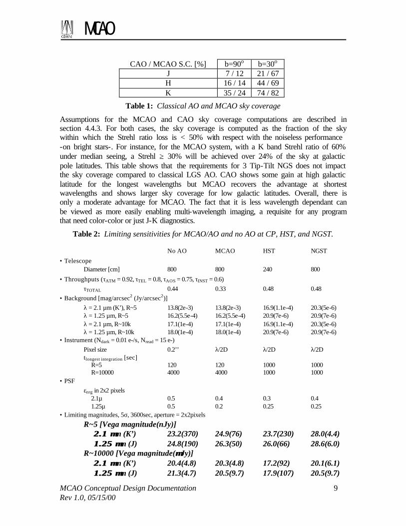
The derived limiting fluxes of a ground-based telescope with MCAO/AO or without AO at Cerro Pachon, the Hubble Space telescope with NICMOS, and the yardstick NGST are presented in Table 2. We list the 5-sigma, 1 hour limiting magnitudes for spectral resolutions of R=5 and R=10000. The backgrounds were taken from either the expected sky backgrounds for Gemini, the NICMOS manual, or from Gillett & Mountain (1997). The encircled energy fraction in the central 2x2 pixels is taken from simulated PSFs for the MCAO, NICMOS NIC2 growth curves (HST Instrument Science Report NICMOS-99-007), or estimated in the case of NGST (“NGST science instrument capability report”, Dec 29, 1999). We reconfirm the results of Gillett and Mountain that at low resolutions NGST has a significant advantage (2.5 – 3 magnitudes) while at high spectral resolutions there is no SNR advantage. At these spectral resolutions detector noise is important and the Gemini advantage arises from the lower cosmic ray flux and hence fewer frame readouts. In broadband imaging at 2.2 microns MCAO has a 1.2-1.7 magnitude advantage over NICMOS and no AO cases respectively. Note that at high spectral resolution the no-AO case has a fainter limiting magnitude than the MCAO but this is through a slit which is 12 times larger (i.e. a 2 pixel slit width). 2.2.3 Sky coverage
Table 1 summarizes the sky coverage for classical LGS AO (CAO) and MCAO, for two galactic latitude and the three near-infrared bands
MCAO
MCAO Conceptual Design Documentation 9 Rev 1.0, 05/15/00
CAO / MCAO S.C. [%] b=90o b=30o J 7 / 12 21 / 67 H 16 / 14 44 / 69 K 35 / 24 74 / 82
Table 1: Classical AO and MCAO sky coverage
Assumptions for the MCAO and CAO sky coverage computations are described in section 4.4.3. For both cases, the sky coverage is computed as the fraction of the sky within which the Strehl ratio loss is < 50% with respect with the noiseless performance -on bright stars-. For instance, for the MCAO system, with a K band Strehl ratio of 60% under median seeing, a Strehl ≥ 30% will be achieved over 24% of the sky at galactic pole latitudes. This table shows that the requirements for 3 Tip-Tilt NGS does not impact the sky coverage compared to classical LGS AO. CAO shows some gain at high galactic latitude for the longest wavelengths but MCAO recovers the advantage at shortest wavelengths and shows larger sky coverage for low galactic latitudes. Overall, there is only a moderate advantage for MCAO. The fact that it is less wavelength dependant can be viewed as more easily enabling multi-wavelength imaging, a requisite for any program that need color-color or just J-K diagnostics.
Table 2: Limiting sensitivities for MCAO/AO and no AO at CP, HST, and NGST. No AO MCAO HST NGST
• Telescope Diameter [cm] 800 800 240 800
• Throughputs (τATM = 0.92, τTEL = 0.8, τAOS = 0.75, τINST = 0.6) τTOTAL 0.44 0.33 0.48 0.48 • Background [mag/arcsec2 (Jy/arcsec2)] λ = 2.1 µm (K’), R~5 13.8(2e-3) 13.8(2e-3) 16.9(1.1e-4) 20.3(5e-6) λ = 1.25 µm, R~5 16.2(5.5e-4) 16.2(5.5e-4) 20.9(7e-6) 20.9(7e-6) λ = 2.1 µm, R~10k 17.1(1e-4) 17.1(1e-4) 16.9(1.1e-4) 20.3(5e-6) λ = 1.25 µm, R~10k 18.0(1e-4) 18.0(1e-4) 20.9(7e-6) 20.9(7e-6) • Instrument (Ndark = 0.01 e-/s, Nread = 15 e-) Pixel size 0.2’’ λ/2D λ/2D λ/2D tlongest integration [sec] R=5 120 120 1000 1000 R=10000 4000 4000 1000 1000 • PSF εnrg in 2x2 pixels 2.1µ 0.5 0.4 0.3 0.4 1.25µ 0.5 0.2 0.25 0.25 • Limiting magnitudes, 5σ, 3600sec, aperture = 2x2pixels
R~5 [Vega magnitude(nJy)] 2.1 µ2.1 µm (K’) 23.2(370) 24.9(76) 23.7(230) 28.0(4.4) 1.25 µ1.25 µm (J) 24.8(190) 26.3(50) 26.0(66) 28.6(6.0) R~10000 [Vega magnitude(µµJy)] 2.1 µ2.1 µm (K’) 20.4(4.8) 20.3(4.8) 17.2(92) 20.1(6.1) 1.25 µ1.25 µm (J) 21.3(4.7) 20.5(9.7) 17.9(107) 20.5(9.7)

MCAO
MCAO Conceptual Design Documentation 10 Rev 1.0, 05/15/00
2.2.4 Multiplex gain
This section addresses the gain in surface area brought by MCAO. To quantify this multiplex gain we must first examine the class of wide field programs that might be addressed:
1. Programs that do not rely on PSF uniformity, other than an approximately constant FWHM, e.g. morphology of relatively bright galaxies, structure of the ISM, color-color photometry in loose and bright clusters
2. Programs that do not rely on PSF uniformity, but that need the SNR gain provided by high Strehl ratio (high Z clusters, stellar population in moderately crowded environments)
3. Programs that rely on a uniform PSF and field of view (arcs/gravitational lenses/weak lensing/high accuracy photometry, e.g. stellar population segregation in globular clusters)
4. Survey programs that require the ultimate sensitivity over large field of view (e.g. survey of Proplids, supernovae at high Z)
The case #3 is quickly settled: These programs (which we will come back to later in this discussion) will hugely benefit – or will simply be enabled- by the uniform image quality of MCAO. For some of them tricky data reduction, as deconvolution or photometry extraction through a field dependant PSF could provide a partial answer, provide –and this is the most difficult- an accurate PSF calibration scheme can be established. Case #4 represents the archetype of programs enabled by the combined MCAO wide field + sensitivity gain. Some of these programs are presented Table 4 and in Section 2.4. Case #1 and #2 is where the multiplex gain applies. Table 3 shows the ratio of the MCAO/CAO area for which the Strehl is larger than Speak/2. This actually compares two comparable quantities -comparing the CAO isoplanatic patch with the MCAO 1 square arcmin central area where the PSF is fully uniform does not mean much.-
Table 3: MCAO and CAO compensated surface area
J H K FoV MCAO Φ [“] 90 110 120 FoV CAO Φ [“] 20 30 40
Area gain 20 13 9 Table 3 shows that, for programs that need field of view, MCAO provides a 10-20 multiplex gain. Such a large number can make possible programs that were not previously –because of the time required to complete. It can also simply increase efficiency, e.g. translate into more time spent on the object(s). This of course requires that this multiplex gain can be exploited, that is, adequate ~ 2 arcmin instrumentation follows. We note that this multiplexing gain is not simply a matter of doing CAO science faster; the field covered by MCAO enables new opportunities. In particular, in cases #1 and #2,

MCAO
MCAO Conceptual Design Documentation 11 Rev 1.0, 05/15/00
for objects larger than the corrected field of view of CAO, the probability to have enough guide stars to mosaic n fields equals the CAO sky coverage to the n-th power. For example, to mosaic a field with Strehl > Speak/2 at 1.65 microns of a galaxy that is 1 arcmin in diameter requires four CAO fields. Using the numbers in Table 1, the probability that there will be guide stars in each of these fields is less than 4% at 30 degrees galactic latitude and considerably less than 1% at the galactic pole. 2.2.5 Uniform PSF
This feature is, as such, unique to MCAO. Although 0.1 magnitude error can be achieved in some cases on field of 10-30” with CAO (c.f. Davidge), a uniform PSF will likely vastly improve the accuracy of the image/spectra analysis. The actual study carried out in the frame of the science case on nearby and distant galaxies (c.f. Appendix A) quantitatively illustrate this gain1. More generally, it is the experience AO users that data reduction is a critical problem, because of (1) the lack of proper and simultaneous PSF calibration and (2) PSF spatial variability in the field. For some programs (e.g. stellar population, sparse to moderately crowded field) a PSF can be found in the field itself, by definition, however small the field is. For the majority of the wide field programs (high Z clusters, galaxy morphology/evolution, YSOs, solar system, ISM), this is not the case. Having a large, uniform field goes a long way toward solving this problem: if a star is present in the field of view (1’x1’), it can be used for the whole 1’x1’ uniform field. Since, by definition there are three m < 19 stars to serve as tip-tilt guide stars in a 2 arcmin diameter field, the probability of having at least one in the central 1 square arcmin field is high (60%). 2.2.5.1 On altitude conjugation
Although altitude conjugated AO is a perfectly valid concept for sites with marked dominant turbulence layer(s) at altitude, it is not applicable for CP (see also section 4.2.1). At CP the relative gains of a single-conjugation AOS were found to be rather small -10% in isoplanatic angle-. This is why such a concept has not been explored for Cerro Pachon, nor considered here for comparison with MCAO. 2.3 MCAO and the Gemini Science program
The science case for MCAO can be drawn from multiple sources: we can start with the Abingdon report. Some are spelled out in the Altair science case and the NIFS science case. We will discuss in the following how MCAO vastly improves the science output of most of these programs. However, none of these science cases considered the possibility of wide field AO, and therefore did not expand on science cases that possibly made the most of the MCAO possibilities. The NGST Design Reference Mission (DRM) constitutes an excellent source of inspiration to build upon the MCAO science case. It is ambitious, but we will see that a significant fraction of its programs are not out of reach of Gemini+MCAO. In fact, MCAO, coupled with the right instrumentation, by its
1 to be precise, the additional scatter in the CAO results for the stellar population case is due primarily to SNR loss in the CAO image. In the distant galaxy morphology study, however, errors of 25-50% are found on e.g. half light radii by mismatching the CAO PSF on and off-axis.

MCAO
MCAO Conceptual Design Documentation 12 Rev 1.0, 05/15/00
relatively wide field and/or increased sensitivity, will position Gemini in between current ground based facilities and the NGST. Before entering the review of the science programs, it is useful to classify the programs into categories that allow comparison of MCAO and Classical AO (CAO). The major step forward brought by MCAO are field of view and PSF uniformity. Sensitivity is similar to that provided by CAO over smaller fields. Three general groups of program can be made: 1. Programs that involve a single isolated compact object (<5”-10”): In general there is
no MCAO advantage. There may be a slight advantage in sky coverage and in calibration of the PSF, if there is appropriate calibration stars in the MCAO field of view. An example of this class of programs is the study of individual stellar disks.
2. Programs that involve a single isolated extended object (10-120”): MCAO brings larger field of view, PSF uniformity and possibly PSF calibration. Note that it is likely that this type of object can not be mapped out entirely by CAO if appropriate guide stars are not in all sub-fields. In these cases MCAO enables new observations. An example of this class of programs is studies of galactic nebulae.
3. Programs involving multiple objects: In addition to PSF uniformity and calibration, MCAO brings a multiplexing advantage of 10-20.
Table 4 presents a review of the generic science programs presented in the Abingdon report. The latter is very general, and it is sometime difficult to estimate its full context. However, we have tried to exercise our best judgment. This table presents each program in light of the MCAO gains. There is no obvious case for which MCAO would actually do worse than classical AO, although there are a number of science programs were an optimized AO+coronograph facility is to be preferred (NICI). The programs that do not require AO, as discussed in the Abingdon report, are indicated in the comment column. The programs are listed in column 2. Column 3 presents the classification of the program, in the terms presented above. Column 4 is a trial to assess the typical object density that can be expected in a 1 arcmin square field. Some of these numbers have been taken in the Altair science case (table 1 of the Altair OCDD document). Columns 5 to 9 check whether a particular MCAO gain is applicable to this science program. “Enabled” means that the program is actually made possible by MCAO, and would be very difficult to complete without it. Most of these programs are survey programs at the limit of sensitivity of an 8-m telescope. Only the coupled gain of field and sensitivity provided by MCAO can allow these programs to be tackled in a reasonable amount of time. “Mult.” is for “multiplexing”, and indicate the program that benefit from it. “FoV” (field of view), “Uni. PSF” (uniform PSF) are self-explanatory. “Cal.PSF” means that this program could benefit from having a calibration of the PSF simultaneous to the observations, as discussed above. “WF.IM” (wide field imager) and “d-IFUs” is for programs that require/will greatly benefit from these focal plane instruments.

MCAO
MCAO Conceptual Design Documentation 13 Rev 1.0, 05/15/00
Com
men
ts
coro
nogr
aph
No
AO
e.
g. e
ta C
ar, g
lobu
les
in P
N e
nv.
Lar
ge A
v, is
sue
for
TT
GS
? N
o A
O n
eede
d Pr
imar
ily
coro
nogr
aph
Lar
ge f
ield
s su
rvey
mod
e A
lso
coro
nogr
aph
FoV
for
out
flow
s (c
oron
o fo
r dr
ivin
g m
echa
nism
s)
Ena
bles
sur
vey
and
calib
ratio
ns
e.g.
bet
a Pi
c
No
AO
Nee
ded
e.g.
R13
6 (>
40”
) se
e A
ppen
dix
A
See
App
endi
x A
Se
e A
ppen
dix
A
1:in
div.
, 2-3
:det
ecti
on/s
urve
y PS
F ca
libra
tion
criti
cal
PSF
cali
brat
ion
impo
rtan
t Se
e N
GST
sec
tion
d-IFUs
X
X X X X
X
X X
X
X
X
“WF” IM
X
X
X X X X
X X
X
X X
X
X
X
X X
Cal
.PS
F
X X X X X X ? X
X
X
Uni
PS
F
X
X X X
X X
X
X X
X
X
X
X X
FoV
X
X
X X X? X X
X X
X
X X
X
X
X
X X
Mul
t.
X X X
X
X
X
X
X
X
X
MC
AO
Gai
n v
s A
O
Ena
-bl
ed
X X X
X
X X
#Obj/p’ 1 - >1
00
>>10
0 1 -
1-10
St
ruct
. St
ruct
. -
Stru
ct.
- >100
>
1000
~2
00
~200
~2
00
~50
~100
1+
1+
<1
Gro
up
1 1 su
rvey
1-
2 3 1 su
rvey
1 1-2
1-2
surv
ey
1-2
1-2-
3 3 2
3 3 3
1-2-
3 2 1-2
1-2
surv
ey
Prog
ram
Plan
et a
nd B
D s
earc
h St
ella
r pr
oper
ties,
sur
face
map
. Fi
eld
Bro
wn
Drw
aves
sur
veys
E
volv
ed s
tar
enve
lope
kin
emat
ic
IMF
Mol
ecul
ar c
loud
s an
d co
re
YSO
: -
disk
s -
Prop
lid
surv
eys
- Je
t mot
ion
- E
nvel
opes
-
Out
flow
s &
jet-
clou
d in
ter.
-
-
Subs
tella
r co
mpa
nion
s -
Deb
ris
disk
s
Mas
s lo
ss
Supe
r st
ar c
lust
er
Stel
lar
popu
latio
n G
alac
tic n
ucle
i (B
.H, A
GN
/sta
rbur
st)
Clu
ster
-
Suny
aev-
Zel
dovi
ch
- C
lust
er a
t z>1
, sur
vey
follo
w u
p
- T
ully
-Fis
her
@ z
>2
Arc
& le
nses
W
eak
lens
ing
AG
N
QSO
hos
t and
abs
orpt
ion
syst
ems
Q0
usin
g su
pern
ovae
Topi
c
Sta
rs a
nd
P
lane
tary
sys
tem
Sta
r fo
rmat
ion
an
d I
SM
Gal
acti
c S
tru
ctu
re
and
Nea
rby
gala
xies
For
mat
ion
an
d
Evo
luti
on O
f g
alax
ies
&
Cos
mol
ogy
Table 4: Summary of the MCAO gain and characteristics of the Abingdon science programs

MCAO
MCAO Conceptual Design Documentation 14 Rev 1.0, 05/15/00
2.4 MCAO in the NGST Era
The competing capabilities in the time frame of MCAO on Gemini are ground-based telescopes with AO (e.g. VLT, Keck) and space-based telescopes (HST & NGST). Classical, single-DM NGS/LGS AO systems (CAO) with similar performance are planned on at least six large aperture telescopes. All of these were designed for use at near-infrared wavelengths and with the exception of the Gemini-North AOS Altair, all have their correcting element conjugate to the ground. To complement these AOS most facilities have focused the focal-plane instrumentation on narrow-field imaging and single-object imaging spectroscopy (i.e. IFU) Each of the Keck, Subaru, and VLT AOS will have a 10242 InSb imager with critically sampled pixel scales, a single-object slit or integral-field spectrograph with R of a few thousand, and each has provisions for adding a single LGS. Keck AO NIRC2: 10242 InSb, Coronographic imaging, R=5k spectroscopy, 9-40mas/pixel NIRSPEC: 10242, 13-74mas slits x 1.1-2.2’ slit lengths, R=2k-27k Subaru AO IRCS, 10242 InSb, R~400-20k, imaging at 0.022’’/pixel and 0.060’’/pixel. CIAO, Coronographic imaging VLT AO CONICA: 10242 InSb, 13.6-109.2’’/pixel, R=350-1400, SINFONI: IFU, 32 x 32 elements 0.35’’-0.05’’/element, 1-2.5µm, R<4500 It is clear that the current set of AOS are geared toward detailed studies of single objects. The main area where MCAO does not excel in this respect is in coronographic studies. However, Gemini/NICI will be optimized to address these science cases. In space there will be HST and NGST. It is very likely that HST will continue to be supported until NGST is online and its capabilities at visible wavelengths are well matched with MCAO. The Advanced Camera for Surveys (ACS), to be installed next year, will provide a Nyquist-sampled field of view of 30” x 30” in the HRC detector and a field-of-view of 3'x3' but with undersampled pixels (0.”049/pixel) in the WF Camera. The HRC detector field of view is comparable to classical single-DM AOS while the WFC provides a field comparable to MCAO. The limiting sensitivity of the ACS (e.g. 27.3 1hr, 10σ in WFC F606W) complements the MCAO broad-band limits making it a good visible wavelength 'companion camera' for MCAO (or vice-versa). At near infrared wavelengths HST will likely have NICMOS during this period but its capabilities will be surpassed by ground-based CAO at 2 microns in field size, angular resolution, and sensitivity. NGST promises to open exciting new frontiers in astronomy with its high angular resolution and low background. The NGST yardstick capabilities as relevant for a comparison with a NIR MCAO system are an 8m primary telescope with a 0.6-5 micron camera with a FOV of 4' x 4', Nyquist sampled at 2 microns (8K x 8K pixels) and a 1-5 microns 100-object MOS with a FOV of 3'x3' and R=100&1000 (Greenhouse et al. (SPIE March 2000)). An illustrative set of science programs for NGST are the Design Reference Mission (DRM) programs. In general these programs are weighted towards

MCAO
MCAO Conceptual Design Documentation 15 Rev 1.0, 05/15/00
large survey programs; guest observing programs will likely differ in scope considerably. As a challenge, we ask the question of whether Gemini with MCAO can address the science goals outlined in the DRMs. Of the 25 DRM programs, 16 exploit NGST capabilities at 1-2.5 microns. Not surprisingly all the programs require some unique capability of NGST to be completed. However, in roughly 11 (or nearly half of all the NGST DRM cases), Gemini with MCAO can begin to explore the science goals. Of the DRM programs that can not be done the limiting factor is either (1) the required wavelength range (i.e. visible or thermal infrared) or (2) the depth of the observations required to achieve the science goals. In the latter case the observations are generally broad-band imaging programs that in several cases push the limiting depths of NGST. For example, the complete program to map the dark matter distribution at high redshift asks for nearly 200 days of observations. Of the 11 cases where MCAO can do some aspect of the DRM program, the main enabling feature of MCAO with respect to other ground based facilities is the field multiplexing advantage. Additionally, some programs such as dark matter gravitational lensing program, classical AO can not do the science due to variations of the PSF across the field. With the launch date for NGST now 2010, it appears that there is a window of ~6 years for Gemini/MCAO to pursue unchallenged NGST science. An analysis of the individual DRM programs and the potential of MCAO is given in the section below. Once NGST is operational, Gemini/MCAO will remain competitive in at least two aspects. First, as outlined by Gillett and Mountain (1997) at spectral resolutions R≥10000 the limiting sensitivity is driven in part by the detector readout noise. They extrapolate detector performance and find that at R~10000, there is little or no sensitivity advantage for space. How big an advantage this is depends on the detector characteristics in the respective instruments. Second, within the yardsitck instrumentation for NGST there is no integral-field spectrograph. For a number of DRMs this is required. Assuming that NGST has a single fixed IFU, there would still be a considerable advantage with MCAO and a deployable IFU spectrograph. Gillett and Mountain (1998) show that at R~1000, NGST will have a factor of 3-5 gain in the SNR over a ground-based. Thus if NGST only has a single IFU, then Gemini/MCAO with a ~15-20 dIFU spectrograph at R~1000 will have performance comparable to NGST. Initial estimates from the gIRMOS design studies suggests that as many as 24 are possible. 2.4.1 Gemini MCAO and NGST DRM programs
The following is a very brief summary of NGST DRM programs and a discussion on how Gemini with MCAO might address this science prior to the launch of NGST. No attempt has been made to explore avenues to the DRM science other than as outlined in the DRM programs. When MCAO can make headway into the DRM science, we note that Further information on the DRM programs can be found at the following web page: http://www.ngst.stsci.edu/drm/programs.html. The programs that target another wavelength range (visible only or thermal/mid-IR) have not been listed.

MCAO
MCAO Conceptual Design Documentation 16 Rev 1.0, 05/15/00
Cosmology and the Structure of the Universe: Mapping the dark matter distribution at high redshift with NGST This program uses weak gravitational lensing in very deep multi-band images to map the dark matter distribution on scales from individual galaxies, through groups and clusters, up to the large-scale matter distribution in the Universe on scales below about 3 Mpc. Mass determinations of clusters to high redshifts will provide strong constraints on the evolution of structure. Photometric redshifts map the distributions into time.
Requirements:
FWHM/ Strehl λ Depth FOV R
0.1’’ to resolve galaxies V to M KAB~26-29 100am2 – 5deg2 5
MCAO Potential: Fair. This program requires large fields to have a statistical ensemble. For example, to map the dark matter distribution, the authors argue that a 5 square degree field is necessary to obtain enough galaxies within different redshift bins to study the evolution of the distribution. Given that the baseline FOV of NGST is 4’x4’ and that NGST has a large advantage in broadband imaging, a study of this scope is not possible. However, the requirements of resolution and depth (at least on the bright end) can be met in ~ 10000 second integrations with Gemini/MCAO so the science could be explored. MCAO advantage over CAO: Classical AO can not access this science because (1) the variation of the PSF will be larger than the weak lensing effects and (2) the multiplexing gain of MCAO is needed. Measuring cosmological parameters with high-z supernovae This program and the program “The evolution of the cosmic supernova rates” use NGST to find high redshift Type Ia supernovae to measure cosmological parameters and the star formation history of the universe.
Requirements:
FWHM/ Strehl λ Depth FOV R
100mas @ 2 microns J to M KAB>28 4’x4’ 5, 100 (redshift)
MCAO Potential: Good. This program requires high-redshift SNe (z>1). With MCAO at K' and a 4k x 4k imaging camera the 10ksec limiting magnitude is about 26 (KAB~28). The figure below is figure 3 from Dahlen and Fransson (1998 Liege NGST Meeting). It shows the predicted number density of Type Ia SNe for different bands (M,K,J,I, and R) for three different time delays (the time between the formation of the progenitor star and the supernova). The y-axis is appropriate for the M-band curves while the other sets are offset by factors of 10. Note that the magnitudes are given in AB magnitudes and that the 5-sigma 10000 sec limit for MCAO on Gemini is KAB ~ 28. MCAO is already on the plateau of the curves and it would take observations of ~2 fields at this depth to find a single Type Ia SNe. Its redshift would likely be around z~1.2 making it of considerable interest. Such a program would require revisiting the fields but in a time similar to that outlined in the DRM, a handful of high redshift Type-Ia SNe at these redshifts would be found. A redshift of the host galaxy would require a low resolution spectrum. MCAO advantage over CAO: multiplexing gain of MCAO is required to obtain a small sample of high-z SNe in a reasonable amount of time. CAO could do this program but
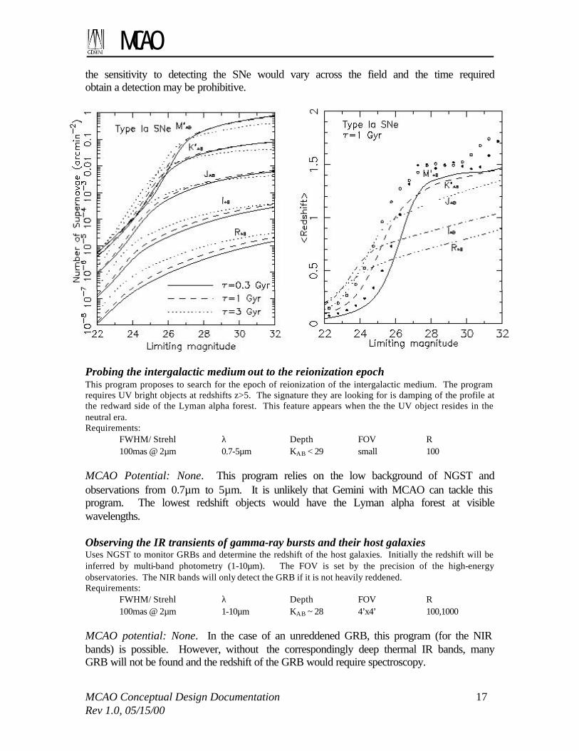
MCAO
MCAO Conceptual Design Documentation 17 Rev 1.0, 05/15/00
the sensitivity to detecting the SNe would vary across the field and the time required obtain a detection may be prohibitive.
Probing the intergalactic medium out to the reionization epoch This program proposes to search for the epoch of reionization of the intergalactic medium. The program requires UV bright objects at redshifts z>5. The signature they are looking for is damping of the profile at the redward side of the Lyman alpha forest. This feature appears when the the UV object resides in the neutral era. Requirements: FWHM/ Strehl λ Depth FOV R 100mas @ 2µm 0.7-5µm KAB < 29 small 100 MCAO Potential: None. This program relies on the low background of NGST and observations from 0.7µm to 5µm. It is unlikely that Gemini with MCAO can tackle this program. The lowest redshift objects would have the Lyman alpha forest at visible wavelengths. Observing the IR transients of gamma-ray bursts and their host galaxies Uses NGST to monitor GRBs and determine the redshift of the host galaxies. Initially the redshift will be inferred by multi-band photometry (1-10µm). The FOV is set by the precision of the high-energy observatories. The NIR bands will only detect the GRB if it is not heavily reddened. Requirements: FWHM/ Strehl λ Depth FOV R 100mas @ 2µm 1-10µm KAB ~ 28 4’x4’ 100,1000 MCAO potential: None. In the case of an unreddened GRB, this program (for the NIR bands) is possible. However, without the correspondingly deep thermal IR bands, many GRB will not be found and the redshift of the GRB would require spectroscopy.

MCAO
MCAO Conceptual Design Documentation 18 Rev 1.0, 05/15/00
Microlensing in the Virgo cluster and the role of baryonic dark matter in the universe This program would monitor the stars in the Virgo cluster for microlensing to map out dark matter within the cluster and M87. Requirements: FWHM/ Strehl λ Depth FOV R 30mas @ 1µm 1µm I~29-30 2’x2’ 5 MCAO Potential: None. The predicted fluctuations are too faint. The Origin and Evolution of Galaxies: The formation and evolution of galaxies I: the deep imaging survey(s) This program is a deep multi-band imaging survey to find the first star-forming systems. Eight filter bands are proposed to measure the spectral energy distributions and obtain photometric redshifts. The deepest field is obtained with 168 hours per field and reaches low star-formation rates at redshifts of z~20-40. A shallower but wider field uses ~10 hours per filter and reaches AB=32.5 and samples the z~1-5 universe. Requirements: FWHM/ Strehl λ Depth FOV R 0.1’’ to resolve galaxies 0.5-5µm AB~32.5 1 sq deg. 5 MCAO Potential: Good. As illustrated in the figure below, MCAO can start probing the brightest galaxies to z~5. MCAO advantage over CAO: There are no preferred locations in the sky for this program so CAO can do similar studies. The MCAO brings multiplexing advantage for imaging and spectroscopy.
Figure 2: Predicted number counts per 5'x5' field of view per logarithmic flux interval in the NGST wavelength range of 1-3.5 micron. The thick lines, labeled 10, correspond to objects located at redshifts z >10, and the thin lines, labeled 5, correspond to objects with z >5. The upper labels on the horizontal axis correspond to Johnson I magnitude (from Haiman & Loeb 1998). See DRM description on web for more details.

MCAO
MCAO Conceptual Design Documentation 19 Rev 1.0, 05/15/00
The formation and evolution of galaxies II: the deep spectroscopic survey(s) This is a spectroscopic followup program to the “The formation and evolution of galaxies” program. Spectra will be obtained at R~100 to get the redshifts of the galaxies (AB~30-31), at R~1000 to estimate metallicities, stellar ages, star-formation rates and dust extinction levels (AB~27), at R~5000 to study the kinematics and provide masses, and with 2d imaging spectroscopy to a small number of galaxies (~20) to study the physical conditions in the star forming regions (AB~24.5). Requirements: FWHM/ Strehl λ Depth FOV R 0.1’’ to resolve galaxies 0.5-5µm AB~25-31 100-3000 MCAO Potential: Fair. At the higher spectral resolutions Gemini with MCAO and a deployable IFU spectrograph will likely do as well as NGST in sensitivity although it will most likely not have the same spectral coverage. This will depend on the sky brightness at R~5000 and the detector read noise characteristics. There is a possible multiplexing advantage if NGST has only one IFU. MCAO advantage over CAO: Field and multiplexing advantage of a dIFU spectrograph. The formation and evolution of galaxies III: cluster galaxies This program is similar to the program “The formation and evolution of galaxies I”. The imaging depth is similar with a goal to observe clusters at z~2. Spectroscopy at R=1000 would be used to obtain line diagnostics as with the field galaxy program. Higher resolution spectroscopy R=10000 would be used to measure kinematics within the galaxies and within the clusters. Requirements: FWHM/ Strehl λ Depth FOV R 100mas @ 2µm 1-10µm 33 at I 2’x2’ 5, 1000, 10000 MCAO Potential: Good. MCAO can probe down to below L* in reasonable integration times. Considerable potential for cluster discovery as well as the kinematic study. MCAO advantage over CAO: Field and multiplexing advantage of a dIFU spectrograph. The formation and evolution of galaxies IV: the relation between galaxy evolution and AGN “The principal objectives of this proposal are to compare AGN hosts with the rest of the galaxy population and elucidate any dependencies on AGN type and environment.” With NGST objects at z>3-6 can be studies in the H-alpha – [SII] line diagnostics.
Requirements:
FWHM/ Strehl λ Depth FOV R 100mas @ 2µm 1-10µm 33 at I 2’x2’ 5, 1000, 10000 MCAO Potential: Good. As stated in the DRM program, ground based telescopes will tackle this program to z~2.5. Note that the field requirement in the DRM was set to also observe field galaxies and absorbing systems. MCAO advantage over CAO: CAO will address this science often using the AGN as the NGS reference source. The evolution of the cosmic supernova rates MCAO Potential: Good. See “Measuring cosmological parameters with high-z supernovae” above.

MCAO
MCAO Conceptual Design Documentation 20 Rev 1.0, 05/15/00
MCAO advantage over CAO: See “Measuring cosmological parameters with high-z supernovae” above. The History of the Milky Way and Its Neighbors The age of the oldest stars from the faint end slope of the white dwarf luminosity function in globular clusters This program proposes to determine the absolute magnitude of the end of the white dwarf cooling sequence in nearby globular clusters. Observations must reach H~30-31 to reach the expected end. Requirements: FWHM/ Strehl λ Depth FOV R 20mas @ 1µm 1µm H~30-31 2’x2’ 5 MCAO Potential: None. Can not reach required depths. A complete initial mass function for old stellar populations Program observes the Galactic bulge, Magellanic Clouds, and the 7 dwarf spheroidals to observe the mass function at the end of the hydrogen burning sequence. In addition to providing a measure of the complete stellar mass function over a range of metallicities, the program will determine the mass function of brown dwarfs in star formation regions. Requirements: FWHM/ Strehl λ Depth FOV R 40mas @ 1.65µm 1.65µm H~29 1’-100’ 5 MCAO Potential: Some. The program can be done in the Galactic bulge. As noted by the authors the main problem will be crowding. MCAO advantage over CAO: This program would be difficult with CAO because: (1) the field of view needed would require stitching together many CAO fields and (2) the field varying PSF would cause variations in the crowding and photometric accuracy. The ages and chemistry of the oldest stellar halo populations This program will measure the main sequence turnoff of stars in the local group. This will be used to compare the age distribution of the stars in the halos of other galaxies. In addition, giants as far out as Virgo can be measured to infer the halo metallicities and their relationship to different Hubble types. Requirements: FWHM/ Strehl λ Depth FOV R 13 @ 0.5µm 0.5-1µm V=30-32 1’-100’ @ 0.5µm 5 MCAO Potential: None. Program requires visible wavelengths and very high Strehls to counter crowding. The Birth and Formation of Stars The origin of sub-stellar mass objects: probing brown dwarfs and extra-solar planets in star-forming regions This program aims to study the mass distributions, circumstellar properties, and atmospheric properties of forming brown dwarfs and plantary mass objects. Requirements: FWHM/ Strehl λ Depth FOV R 30mas @ 1µm J-N KAB~26-30 4’x4’ 5,3000

MCAO
MCAO Conceptual Design Documentation 21 Rev 1.0, 05/15/00
MCAO Potential: Fair. As noted by the authors, the groundbased telescope will perform a similar study down to brown dwarf masses. MCAO enables this study by multiplexing to get statistically reasonable field sizes and a stable constant PSF across the field to find the objects. MCAO advantage over CAO: Once objects are identified CAO can be used. CAO can be used to search of objects as well in specific regions. Dynamics and evolution of the interstellar medium: cosmic recycling This program explores the evolution of the ISM and what its enrichment and energetics are. A number of observational programs are included from narrow-band imaging to high resolution spectroscopy. Requirements: FWHM/ Strehl λ Depth FOV R 50mas @ 2µm J-N KAB~14-18 10’x10’ 10000-100000 MCAO Potential: Good. Other than field coverage (which may still be an issue with NGST), all NIR parts of this program can be done as outlined in the DRM. This would require a minimum R=10000 spectrograph and a wide-field imager. MCAO advantage over CAO: CAO’s varying PSF will affect the morphology, and sensitivity across the field. Directed high resolution on specific objects can be done with CAO. The Origin and Evolution of Planetary Systems Detection and characterization of extra-solar planets “A program aimed at the detection and characterization of planets over a range of mass, age, stellar spectral type, and physical separation from their central stars.” Requirements: FWHM/ Strehl λ Depth FOV R 109 in constrast J-M <1µJy small FOV 5,30000 MCAO Potential: None as outlined in the DRM. Requires high contrast. Spectroscopy will be difficult for NGST as well. Detection and characterization of Jovian Planets and Brown Dwarf Companions in the Solar Neighborhood This program will try to directly image brown dwarfs to Jupiter mass objects around nearby stars in the M-band. Spectroscopic follow up is included. Requirements: FWHM/ Strehl λ Depth FOV R 106 in constrast N ? small FOV 5,100 MCAO Potential: Fair. As noted by the authors, ground-based AO telescope will study the brighter, farther separated brown dwarfs, at shorter wavelength. MCAO advantage over CAO. No specific advantage but MCAO may provide better PSF calibrations. A survey of the trans-Neptunian region An imaging survey to map the structure of the Kuiper belt. Requirements:

MCAO
MCAO Conceptual Design Documentation 22 Rev 1.0, 05/15/00
FWHM/ Strehl λ Depth FOV R 0.6-3µm R~30-31,K~28.5 4’x4’ 5 MCAO Potential: None. As outlined in the DRM this program requires large fields of view and deep imaging. 2.5 The science requirements
After having reviewed the science case and established the broad domain of application of MCAO, let us derive the requirements for the system. In establishing these requirements, a number of parameters have to be considered and balanced: 1. Sensitivity 2. Field of view 3. Resolution 4. PSF uniformity 5. Sky coverage 6. Wavelength range Other non-science drivers that we have to keep in mind when specifying the system are: 1. Potential instrumentation: How can it take advantage of MCAO? What can
realistically be done? 2. Cost/schedule constraints 3. Risks/complexity 4. Technology availability One of the problems we face in specifying the system is that all these science parameters are not independent (for instance there is an obvious trade-off between field of view, sensitivity and PSF uniformity). In the discussion below, we have made use of our knowledge of the system performance that was investigated in parallel with this science case. 1. Sensitivity is a vital parameter to address most of the Gemini and NGST science
programs. It will be driven by the MCAO throughput and Strehl ratio • MCAO optical throughput should be larger than 75% • Strehl ratio: Considering the telescope + instrument error budget, plus the
technology limits (computing power, DM power supplies, WFS readout), a Strehl similar to what was specified for Altair is adequate; 40% Strehl ratio at H band at zenith angle < 15 degrees, under median seeing conditions. Commensurate performance at other wavelengths. The MCAO system itself and the future instruments optical quality should introduce as little aberrations as possible. Requirement of a Strehl > 95% for the AO module and S > 95% for the instrument, assuming 80 modes are compensated by the MCAO system.
• FWHM: The Strehl ratio specified above implies that the diffraction limit, in term of resolution, will be reached.
2. Sky Coverage should be maximized too. As a guideline, it should be similar or larger than the sky coverage value achieved with a single LGS/TTNGS system everywhere

MCAO
MCAO Conceptual Design Documentation 23 Rev 1.0, 05/15/00
in the sky (≥ 10% at the galactic pole is acceptable). Using laser guide stars is a requirement.
3. Field of view: This is a critical parameter. It has a large weight in the multiplex gain one can achieve with MCAO. However, there is a trade-off. For instance, enlarging the field of view means reducing the Strehl ratio and resolution, therefore the sensitivity, but potentially also means -if one is ready to drill a hole in the instrument support structure, - larger sky coverage. Worse PSF uniformity is also a price to pay when enlarging the field of view. Because: • Sensitivity is of major importance • Guide stars constellations covering more than 1 square arcmin induce significant
Strehl loss and large PSF uniformity variation everywhere in the field, including close to the center.
• Mechanics limits the field to 2 arcmin in diameter • Image quality should be as uniform as possible, especially at the center of the
field over the imager field of view • 8k x 8k imager are unlikely and imager should not be grossly undersample • many science programs have a sufficient number of objects to feed multiple IFUs
in a 90” field if view We feel that an imager covering a field of 70-85” is appropriate, together with a d-IFU covering the whole 2’ transferred through the AO input window. Therefore, the field should be as uniform as possible in the central region covered by the imager. The Strehl ratio outside of this region should be maximized, in view of spectroscopic applications with potentially a slightly large field (2 arcmin circular versus 70-85” square).
4. PSF uniformity has been addressed within the point above. 3% rms variations over the central 1 square arcmin field of view is acceptable, but a goal is to lower this to 1.5%. A scheme to predict the PSF variation due to image motion across the field will have to be worked out, leading to accuracy of 15% of better on the image’s FWHM.
5. Wavelength range: AO gives its best in the near infrared. Therefore the MCAO should concentrate on the 1-2.5 microns regime. However the 0.8-1 microns is also an interesting range, and should be considered. Observations up to 5 microns should not be precluded.

MCAO
MCAO Conceptual Design Documentation 24 Rev 1.0, 05/15/00
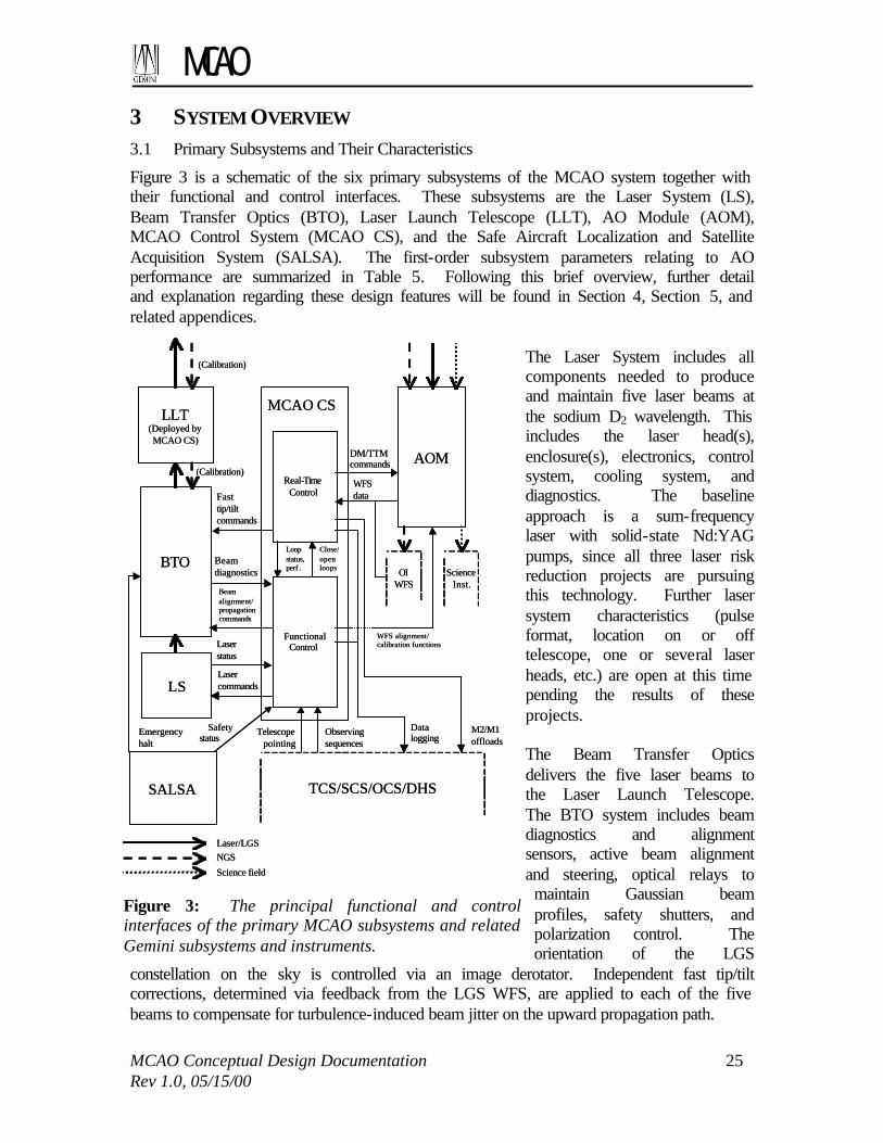
MCAO
MCAO Conceptual Design Documentation 25 Rev 1.0, 05/15/00
3 SYSTEM OVERVIEW 3.1 Primary Subsystems and Their Characteristics
Figure 3 is a schematic of the six primary subsystems of the MCAO system together with their functional and control interfaces. These subsystems are the Laser System (LS), Beam Transfer Optics (BTO), Laser Launch Telescope (LLT), AO Module (AOM), MCAO Control System (MCAO CS), and the Safe Aircraft Localization and Satellite Acquisition System (SALSA). The first-order subsystem parameters relating to AO performance are summarized in Table 5. Following this brief overview, further detail and explanation regarding these design features will be found in Section 4, Section 5, and related appendices.
The Laser System includes all components needed to produce and maintain five laser beams at the sodium D2 wavelength. This includes the laser head(s), enclosure(s), electronics, control system, cooling system, and diagnostics. The baseline approach is a sum-frequency laser with solid-state Nd:YAG pumps, since all three laser risk reduction projects are pursuing this technology. Further laser system characteristics (pulse format, location on or off telescope, one or several laser heads, etc.) are open at this time pending the results of these projects. The Beam Transfer Optics delivers the five laser beams to the Laser Launch Telescope. The BTO system includes beam diagnostics and alignment sensors, active beam alignment and steering, optical relays to maintain Gaussian beam profiles, safety shutters, and polarization control. The orientation of the LGS
constellation on the sky is controlled via an image derotator. Independent fast tip/tilt corrections, determined via feedback from the LGS WFS, are applied to each of the five beams to compensate for turbulence-induced beam jitter on the upward propagation path.
Figure 3: The principal functional and control interfaces of the primary MCAO subsystems and related Gemini subsystems and instruments.
LS
SALSA
LLT(Deployed byMCAO CS)
BTO
AOM
TCS/SCS/OCS/DHS
OIWFS
ScienceInst.
Laser/LGSNGS
Science field
(Calibration)
(Calibration)Real-Time
Control
FunctionalControl
MCAO CS
Emergencyhalt
Safetystatus
Telescopepointing
Observingsequences
Datalogging
M2/M1offloads
Lasercommands
Laserstatus
Fasttip/tiltcommands
Beamalignment/propagationcommands
Beamdiagnostics
WFSdata
DM/TTMcommands
Loopstatus,perf .
Close/openloops
WFS alignment/calibration functions

MCAO
MCAO Conceptual Design Documentation 26 Rev 1.0, 05/15/00
The Laser Launch Telescope is located on-axis and mounted upon the Secondary Support Structure. The primary mirror of the LLT is deployable so that the secondary mirror central baffle (hole) will remain functional when the MCAO system is not in use. A triangular mounting truss provides alignment repeatability with a goal of 1 arc second, and the optical axis of the LLT is recalibrated after each deployment by observing a bright star with the BTO beam diagnostics. The overall mass budget for the LLT and collocated components of the BTO is 125 kg. Like Altair, the AO Module is mounted on the Instrument Support Structure (ISS), and in effect serves as an optical relay between the telescope cassegrain focus and another Gemini science instrument. The location of the focal plane is preserved, but unlike Altair, the focal ratio of the output beam is adjusted from f/16 to f/30. The optical path through the AO Module includes three stacked-actuator deformable mirrors located in collimated space between two off-axis parabolas. The second of these parabolas serves as the fast tip/tilt mirror. After this mirror the light is split spectrally into science, LGS, and NGS optical paths. The AO Module includes five LGS Shack-Hartmann WFS’s, which will be implemented using either one or five lenslet arrays, cameras, and high-speed CCD arrays. Three NGS quadrant detector tip/tilt sensors will be implemented as fiber-fed avalanche photo-diodes located behind optical pyramids. Also, a higher-order Shack-Hartmann NGS WFS is
Laser Subsystems (Laser, LLT, BTO)
Number of LGS 5 LGS locations in field (0’,0’), (+/-30’,+/-30’) LGS signal level at WFS 125 PDE’s/cm2/sec
(May be relaxed to 80 if necessary) Transmitted beam quality 1.5 times diffraction limited RMS 1-axis beam jitter on sky 0.05” (0.025” goal) Transmitted beam 1/e2 diameter 0.3 m Launch telescope aperture, location 0.45 m, on-axis AO Module
Number of DM’s 3 DM conjugate ranges 0.0, 4.5, 9.0 km Actuator pitch (output space) D/16, D/16, D/8
Number of WFS 5 (LGS) 3 (NGS) WFS order 16 by 16 Tip/tilt WFS pixel subtense on sky 1.0” 0.5” WFS read noise 6 electrons None AOM transmittance to WFS 0.7 0.7 WFS detector quantum efficiency 0.85 0.6 WFS sampling rate 800 Hz
Control System (Real time control)
Control algorithm Zonal (LGS) Adaptive modal (NGS) Processing latency + WFS read time 1.25 ms <<1.25 ms -3 dB closed loop bandwidth 32 Hz Adjustable (0-90 Hz)
Table 5: Selected subsystem parameters determining MCAO Performance
MCAO
MCAO Conceptual Design Documentation 27 Rev 1.0, 05/15/00
under consideration for use as a non-real-time calibration- and diagnostics sensor. The LGS WFS’s are adjustable in focus to match the current range of the laser guide stars, and the NGS WFS’s are mounted on probe arms to patrol a one arc minute radius field. The AO Module includes atmospheric dispersion correctors for the NGS- and science optical paths, as well as source simulators for WFS calibration and alignment. The WFS camera digitizers, real time control electronics, and DM high voltage amplifiers are also packaged within the AO Module and mounted on the ISS. The MCAO Control System controls the alignment, operation, and diagnostics of the remaining MCAO subsystems, and will interface these subsystems with the Telescope, Secondary, and Observatory Control Systems. It will be embodied in two EPICS/VxWorks-based VME crates, with one dedicated to the AO Module and the second serving the remaining MCAO subsystems. Non-time-critical control functions will be executed via EPICS over the VME backplane. Time-critical control interfaces external to the MCAO system, such as offloading tip/tilt corrections to the secondary mirror, will be implemented using reflective memory. Finally, the real-time wave front control computations and associated background optimization tasks will be performed on specialized RISC CPU boards. The SALSA system includes a bore-sighted aircraft camera, all-sky aircraft cameras, and any available radar feeds from local traffic control agencies. Laser traffic control will also be coordinated with SOAR and other local telescopes. The procedures for predictive avoidance of artificial satellites, and whether they will be compatible with queue-based observing, have yet to be determined. 3.2 System Performance
3.2.1 Image Quality
Table 6 summarizes the image quality error budget for the MCAO system for the ideal case of bright natural guide stars. Wave front aberrations are expressed in terms of RMS nanometers, and the Strehl ratios have been computed using the Marechal approximation, S=exp(-φ2). The values tabulated under telescope limitations are the standard Gemini specifications as taken from the Altair error budget. The values listed as instrument limitations assume new instruments developed for MCAO that incorporate higher-order, on-instrument WFS’s for calibration of non-common path errors. Both sets of estimates will need to be reviewed based upon Gemini-North telescope performance and the instrument designs actually developed for MCAO, but at the moment they represent the best performance predictions available.
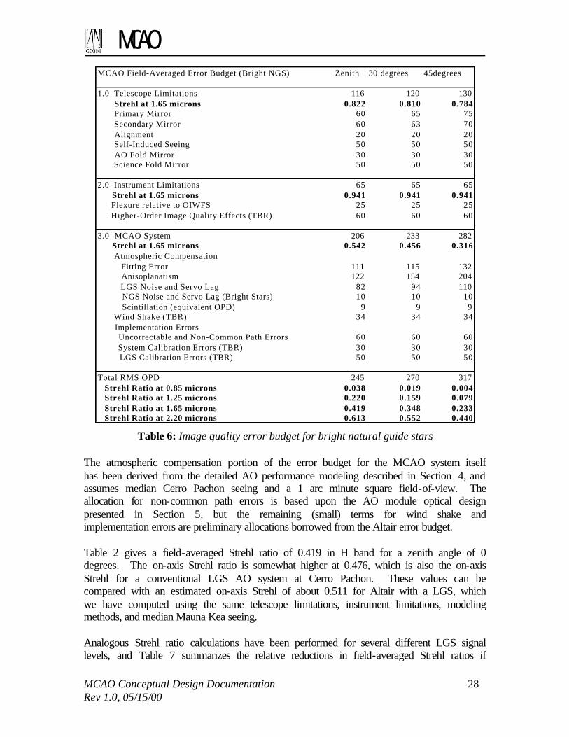
MCAO
MCAO Conceptual Design Documentation 28 Rev 1.0, 05/15/00
The atmospheric compensation portion of the error budget for the MCAO system itself has been derived from the detailed AO performance modeling described in Section 4, and assumes median Cerro Pachon seeing and a 1 arc minute square field-of-view. The allocation for non-common path errors is based upon the AO module optical design presented in Section 5, but the remaining (small) terms for wind shake and implementation errors are preliminary allocations borrowed from the Altair error budget. Table 2 gives a field-averaged Strehl ratio of 0.419 in H band for a zenith angle of 0 degrees. The on-axis Strehl ratio is somewhat higher at 0.476, which is also the on-axis Strehl for a conventional LGS AO system at Cerro Pachon. These values can be compared with an estimated on-axis Strehl of about 0.511 for Altair with a LGS, which we have computed using the same telescope limitations, instrument limitations, modeling methods, and median Mauna Kea seeing. Analogous Strehl ratio calculations have been performed for several different LGS signal levels, and Table 7 summarizes the relative reductions in field-averaged Strehl ratios if
Table 6: Image quality error budget for bright natural guide stars
MCAO Field-Averaged Error Budget (Bright NGS) Zenith 30 degrees 45degrees
1.0 Telescope Limitations 116 120 130 Strehl at 1.65 microns 0.822 0.810 0.784 Primary Mirror 60 65 75 Secondary Mirror 60 63 70 Alignment 20 20 20 Self-Induced Seeing 50 50 50 AO Fold Mirror 30 30 30 Science Fold Mirror 50 50 50
2.0 Instrument Limitations 65 65 65 Strehl at 1.65 microns 0.941 0.941 0.941 Flexure relative to OIWFS 25 25 25 Higher-Order Image Quality Effects (TBR) 60 60 60
3.0 MCAO System 206 233 282 Strehl at 1.65 microns 0.542 0.456 0.316 Atmospheric Compensation Fitting Error 111 115 132 Anisoplanatism 122 154 204 LGS Noise and Servo Lag 82 94 110 NGS Noise and Servo Lag (Bright Stars) 10 10 10 Scintillation (equivalent OPD) 9 9 9 Wind Shake (TBR) 34 34 34 Implementation Errors Uncorrectable and Non-Common Path Errors 60 60 60 System Calibration Errors (TBR) 30 30 30 LGS Calibration Errors (TBR) 50 50 50
Total RMS OPD 245 270 317 Strehl Ratio at 0.85 microns 0.038 0.019 0.004 Strehl Ratio at 1.25 microns 0.220 0.159 0.079 Strehl Ratio at 1.65 microns 0.419 0.348 0.233 Strehl Ratio at 2.20 microns 0.613 0.552 0.440
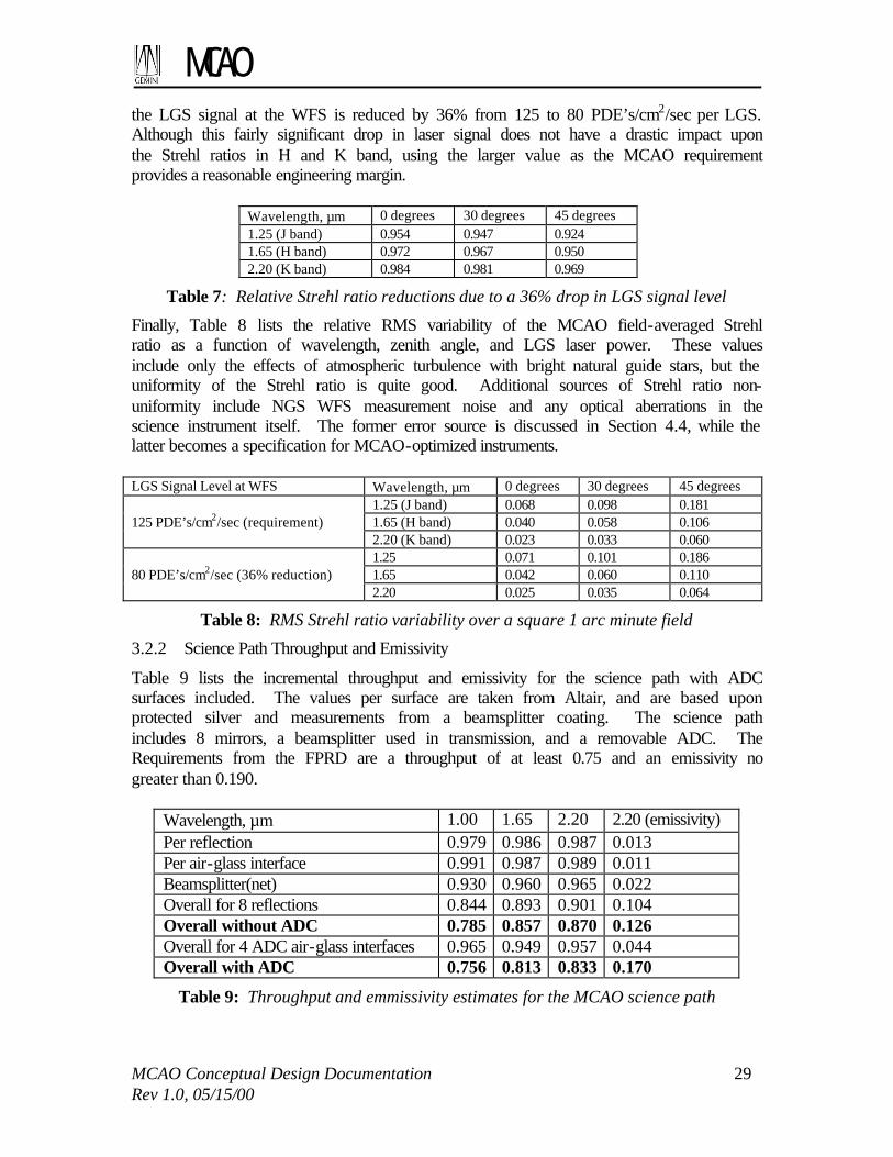
MCAO
MCAO Conceptual Design Documentation 29 Rev 1.0, 05/15/00
the LGS signal at the WFS is reduced by 36% from 125 to 80 PDE’s/cm2/sec per LGS. Although this fairly significant drop in laser signal does not have a drastic impact upon the Strehl ratios in H and K band, using the larger value as the MCAO requirement provides a reasonable engineering margin.
Wavelength, µm 0 degrees 30 degrees 45 degrees 1.25 (J band) 0.954 0.947 0.924 1.65 (H band) 0.972 0.967 0.950 2.20 (K band) 0.984 0.981 0.969
Table 7: Relative Strehl ratio reductions due to a 36% drop in LGS signal level
Finally, Table 8 lists the relative RMS variability of the MCAO field-averaged Strehl ratio as a function of wavelength, zenith angle, and LGS laser power. These values include only the effects of atmospheric turbulence with bright natural guide stars, but the uniformity of the Strehl ratio is quite good. Additional sources of Strehl ratio non-uniformity include NGS WFS measurement noise and any optical aberrations in the science instrument itself. The former error source is discussed in Section 4.4, while the latter becomes a specification for MCAO-optimized instruments. LGS Signal Level at WFS Wavelength, µm 0 degrees 30 degrees 45 degrees
1.25 (J band) 0.068 0.098 0.181 1.65 (H band) 0.040 0.058 0.106
125 PDE’s/cm2/sec (requirement)
2.20 (K band) 0.023 0.033 0.060 1.25 0.071 0.101 0.186 1.65 0.042 0.060 0.110
80 PDE’s/cm2/sec (36% reduction)
2.20 0.025 0.035 0.064
Table 8: RMS Strehl ratio variability over a square 1 arc minute field
3.2.2 Science Path Throughput and Emissivity
Table 9 lists the incremental throughput and emissivity for the science path with ADC surfaces included. The values per surface are taken from Altair, and are based upon protected silver and measurements from a beamsplitter coating. The science path includes 8 mirrors, a beamsplitter used in transmission, and a removable ADC. The Requirements from the FPRD are a throughput of at least 0.75 and an emissivity no greater than 0.190.
Wavelength, µm 1.00 1.65 2.20 2.20 (emissivity) Per reflection 0.979 0.986 0.987 0.013 Per air-glass interface 0.991 0.987 0.989 0.011 Beamsplitter(net) 0.930 0.960 0.965 0.022 Overall for 8 reflections 0.844 0.893 0.901 0.104 Overall without ADC 0.785 0.857 0.870 0.126 Overall for 4 ADC air-glass interfaces 0.965 0.949 0.957 0.044 Overall with ADC 0.756 0.813 0.833 0.170
Table 9: Throughput and emmissivity estimates for the MCAO science path

MCAO
MCAO Conceptual Design Documentation 30 Rev 1.0, 05/15/00

MCAO
MCAO Conceptual Design Documentation 31 Rev 1.0, 05/15/00
4 SYSTEM MODELING 4.1 Goals and Tools
During the conceptual design phase, the principal goal of the system modeling effort has been to determine the highest degree of atmosphere turbulence compensation which can realistically be achieved using MCAO on Gemini-South, and in particular:
• Define the first-order characteristics of the system in terms of order of correction, DM conjugate ranges, LGS configuration, and the corrected field-of-view;
• Quantify system performance as a function of LGS signal level and establish a baseline laser power requirement;
• Determine NGS magnitude limits and initial sky coverage estimates; • Evaluate the characteristics of MCAO-corrected PSF’s; • Interpret these results for particular science instruments and applications; and • Compare MCAO performance against Altair at Mauna Kea and a conventional
LGS AO system at Cerro Pachon.
These goals have been achieved. Along the way we have developed a formulation for the MCAO wave front control algorithm that significantly simplifies sky coverage analysis, and also reduces real-time computation requirements while maintaining near-optimal performance. The principal modeling tools used for detailed performance evaluation have been described in the Feasibility Study report. These two codes are a Monte Carlo time domain simulation and an analytical linear systems model. Both approaches provide an integrated treatment of the four fundamental error sources for astronomical AO systems (DM/WFS fitting error, WFS measurement noise, time delay, and general anisoplanatism). For common input the two codes yield highly consistent results, although the analytical approach yields modestly superior performance for high-order MCAO systems through the use of minimal variance control algorithms derived from atmospheric turbulence statistics. On the other hand the Monte Carlo simulation is faster to run, especially to evaluate PSF characteristics. At this point the other image quality error sources enumerated in Table 6 have been included as multiplicative factors when evaluating Strehl ratios and OTF’s. Both modeling codes assume geometrical optics, although the effect of scintillation has been estimated in a side calculation as described in Section 4.2.3 below. Implementation error sources, such as WFS saturation and WFS/DM misregistration, are also not yet treated in an integrated fashion. As the project progresses, we intended to incorporate as many of these effects as is practical into the simulation to help in determining specifications and tolerances for hardware components. We will also continue studies of control algorithms, particularly in the areas of (i) real-time parameter optimization for changing atmospheric conditions, (ii) verifying loop stability, (iii) improving PSF uniformity, and (iv) estimating the compensated PSF for image post-processing.

MCAO
MCAO Conceptual Design Documentation 32 Rev 1.0, 05/15/00
4.2 Background
This section contains a brief summary of Cerro Pachon atmospheric statistics and some background information on two basic aspects of our approach to implementing MCAO. 4.2.1 Cerro Pachon Site Characterization Summary
The Cerro Pachon site characterization campaign took place in 1998 and consisted of four Generalized-SCIDAR runs at CTIO (January, April, June, October), bimonthly balloon launches at Cerro Pachon, and a week of Generalized Seeing Monitor observations at Pachon. The campaign was conducted by Jean Vernin of the University of Nice. Table 10 is a summary of the atmospheric conditions found in the study. All parameters are specified as mean values at 0.55 microns. Further details may be found in the final report at the Gemini AO documentation archive page (http://www.gemini.edu). G-SCIDAR1 G-SCIDAR2 Balloon GSM Seeing [arcsec] mean/median 0.85/0.733 0.89/0.783 0.67 0.83 θ0 [arcsec] 2.1 2.1 2.1 2.8 τ0 [msec] 4.8 5.4 4.9 d0 [meters] 3.7 3.8 hDMopt [km above site]4 2.7 2.5 L0 [meters] 36 Scintillation [%] 17.3 17.2 15.7 1.9
Table 10: Summary of results for the Cerro Pachon site characterization campaign 1 Generalized SCIDAR analysis with dome seeing removed and ambiguous zero-altitude turbulence attributed to dome seeing. 2 Generalized SCIDAR results with dome seeing removed and ambiguous zero-altitude turbulence attributed to ground layer seeing. 3 Median values were recalculated from the profiles by M. Chun. From this analysis the mean values are slightly smaller (<5%) than the values taken from the Final Report of Vernin et al. 4 The optimal conjugation altitude is determined by minimizing the integral of (h-hopt)
2 CN2(h).
Most of the turbulence is near the ground but occasional strong layers at high altitudes (10-15km above the site) do appear. The optimal conjugate altitude for a single DM is about 2.5-2.7 km above the site and yields only a very modest improvement in the isoplanatic angle. An average G-SCIDAR profile was obtained as an average of several hundred profiles with median integrated strengths (median r0). A discrete 7-layer fit was made by fitting one-dimensional Gaussians to this profile. Table 11 below gives the relative strength of the layers and their wind velocities deduced from measured balloon wind velocity profiles.

MCAO
MCAO Conceptual Design Documentation 33 Rev 1.0, 05/15/00
Altitude [km above sea
level]
Relative turbulence strength
Wind velocity [m/s]
2.7 0.647 6.6 4.5 0.080 12.4 6 0.119 8.0
8.5 0.035 33.7 10.1 0.025 23.2 15.8 0.080 22.2 18.5 0.015 8.0
4.2.2 The Need for Multiple Tip-Tilt Natural Guide Stars
Conventional LGS AO systems include an auxiliary NGS WFS to measure tip/tilt because the exact location of the LGS on the sky is variable and unknown. Analogously, the Gemini-South MCAO system will include multiple tip/tilt NGS WFS to measure modes of tilt anisoplanatism that cannot be detected using tilt-removed LGS WFS measurements alone. Figure 4 illustrates the notation needed for a brief explanation of this requirement. Consider a one-dimensional atmosphere with two phase screens s1(x) and s2(x) at ranges 0 and h. For a NGS or science target in direction θ the net phase accumulated through the two screens is φn=s1(x)+s2(x+hθ). If these two phase screens are canceling focus aberrations, e.g. s1(x)=x2 and s2(x)=-x2, then the resulting phase screen is given by φn(x)=-2hθx-(hθ)2. This is a wave front tilt error that varies with the direction θ of the source, which is precisely tilt anisoplanatism. Now for a LGS at range H in direction θ, the tilt removed component of the WFS measurements through the same phase screens is [1-(1-(h/H))2]x2 due to the cone effect. This measurement is independent of the direction θ of the LGS, and tilt anisoplanatism cannot be distinguished from a uniform focus error over the entire field. Similar arguments apply in two dimensions to astigmatic aberrations of the form xy or x2-y2, so there are a total of three tilt anisoplanatism modes that are undetectable from the LGS WFS measurements.
Table 11: Discrete 7-layer fit to the median Cerro Pachon turbulence conditions used for MCAO performance analysis.
Figure 4: Quadratic atmospheric phase screens induce tilt anisoplanatism that cannot be detected from tilt-removed LGS WFS measurements.
Aperture
Screen s1(x)=x2
at range 0
Screen s2(x)=-x2
at range h
Net aberration φn(x)=-2θhx for a sourcein direction θ is tilt anisoplanatism

MCAO
MCAO Conceptual Design Documentation 34 Rev 1.0, 05/15/00
The MCAO system for Gemini-South will measure tilt anisoplanatism directly using three tip/tilt natural guide stars, and these errors will then be compensated using the multiple DM’s just as any other wave front aberration. The three other approaches to measuring tilt anisoplanatism that were considered were:
• Tilt sensing using LGS, which was rejected as too speculative; • Higher-order WFS measurements from a single NGS. In principle, this approach
might work because the difference between NGS and LGS WFS measurements provides an indication of the high-altitude turbulence that is the source of tilt anisoplanatism. Our analysis indicates disappointing results, at least for a relatively low-order NGS WFS that would provide acceptable sky coverage.
• Higher-order WFS measurements from both Rayleigh- and Sodium LGS. This approach might also work by identifying the high-altitude component of the turbulence, but it would introduce the significant complication of additional lasers at a second wavelength.
4.2.3 Scintillation Effects and the Ordering of Deformable Mirrors
Because of the effects of scintillation and diffraction, the ordering of deformable mirrors has an impact upon the theoretical best-case performance achievable using MCAO. The DM’s should ideally be placed in the reverse order of the phase screens for which they correct to avoid nonlinear cross-coupling between these corrections. However, placing the DM’s in this order would entail a separate optical relay for each deformable mirror and is highly impractical. When the DM’s are placed in the same order as the phase screens for which they compensate, the pupil imaging between each DM and its conjugate plane in the atmosphere is distorted by the intervening mirrors and phase screens. This effect can become significant for sufficiently strong turbulence, but appears to be almost negligible for near IR wavelengths at astronomical sites with good seeing. Wave optics propagation simulations for a highly idealized AO system and atmosphere have been used to bound the magnitude of this effect. These calculations are based upon a three-layer fit to the median Cerro Pachon turbulence profile, with the altitudes of the layers matched to the 0, 4.5, and 9.0 km DM conjugates used in the MCAO optical system design. The system aperture is the entire propagation grid, and the phase correction for each DM is set to geometrically cancel the phase screen at the conjugate altitude. Perfect correction is in fact obtained when the DM’s are placed in the theoretically correct order. When they are placed in the reverse (practical) order the Strehl ratio at 1.65 µm is reduced to 0.998, which is equivalent to the RMS OPD of 9 nanometers listed in Table 6 for this effect. For comparison, the effect of scintillation on the performance of an ideal, conventional AO system was similarly evaluated by correcting the total phase error with a single DM conjugate to h=0. The J band Strehl ratio computed for this case is actually somewhat smaller at 0.993, which is consistent with the log-amplitude variance predicted by Rytov theory for this three-layer turbulence profile. These simulations do indicate that the MCAO performance loss due to scintillation does eventually begin to increase at visible wavelengths.
MCAO
MCAO Conceptual Design Documentation 35 Rev 1.0, 05/15/00
4.3 Optimization and Trade Studies
The trade studies to select the first-order AO system parameters have been based upon a combination of standard AO scaling laws, practical hardware considerations, and (as required) detailed modeling. Jointly optimizing all of the system design parameters (DM orders, DM ranges, science field-of-view, guide star locations, etc.) by detailed analysis and simulation is clearly intractable, and at times we have been forced to proceed using our best judgment one variable at a time. Four of these trade studies are summarized below, and Table 6 in the preceding section lists the resulting overall performance estimates for the MCAO system. 4.3.1 Order of Sensing and Correction
The baseline order of sensing and correction is sixteen WFS subapertures and DM actuators across the diameter of the pupil. This choice is driven by the median seeing at the Cerro Pachon site and practical hardware considerations. The median r0 of 0.166 m at a wavelength of 0.55 µm corresponds to 0.62 m in H band. For a Shack-Hartmann-based AO system the Strehl ratio due to DM/WFS fitting error can be estimated with reasonable accuracy using the formula S=exp(-Cf(w/r0)5/3), where Cf is the fitting error coefficient and w is the width of a subaperture in the plane of the primary mirror. Using Cf=0.3 for the usual Fried WFS/DM geometry yields Strehl ratios in H band of about 0.718 for 12 by 12 subapertures, 0.816 for 16 by 16, and 0.868 for 20 by 20. This last value is comparable to the fitting error Strehl predicted for Altair with only 12 by 12 subapertures, which is consistent with the ratio of the median seeing values for Mauna Kea and Cerro Pachon. Unfortunately, our judgment is that an MCAO system of order 20 by 20 is too risky due the required guide star laser powers. The cost of the multiple deformable mirrors, real-time control electronics, and particularly the lasers would also grow well beyond the estimates presented in the feasibility study. However, reducing the order of the system any further from 16 by 16 to 12 by 12 would degrade the nominal Strehl in H band by an additional 12%. More generally, this reduction would narrow the system’s operating range as follows:
• Seeing: Must improve by a factor of 16/12=1.33 for equal performance; • Wavelength: Must increase by a factor of (16/12)5/6=1.27; • Air Mass: Must decrease by a factor of (12/16)5/3=0.619.
These ratios are large enough in our view to justify the increased cost and greater laser power required for a system of order 16 by 16. For the Gemini-South MCAO system design there are actually three deformable mirrors to specify. By varying these parameters individually, we find that the order of the uppermost DM conjugate to 9.0 km can be reduced from 16 by 16 to 8 by 8 without an appreciable increase in fitting error. This result is consistent with the vertical distribution of turbulence at Cerro Pachon. Similarly reducing the order of the DM conjugate to h=4.5 km has a larger impact upon system performance, so we have specified orders of 16, 16, and 8 actuators across a collimated beam for the 3 DM’s. Section 5 translates

MCAO
MCAO Conceptual Design Documentation 36 Rev 1.0, 05/15/00
these values into actuator geometries for each mirror, signal processing requirements, and CCD array requirements for each LGS WFS. 4.3.2 Deformable Mirror Conjugate Ranges
The baseline conjugate ranges for the three deformable mirrors are 0.0, 4.5, and 9.0 km. In theory, increasing the range for the third DM would yield an improved 3-layer fit to the Cerro Pachon turbulence profile and provide somewhat better performance for an ideal MCAO system with perfect knowledge of the turbulence. In practice, appreciably increasing the range for the third DM is not attractive because:
• Packaging the AO module optical design and fabricating the off-axis parabolas becomes more difficult;
• The clear aperture and number of actuators required for the third DM increase; • The performance improvement actually achieved with 5 LGS WFS is not
significant, as tomography becomes more difficult with the decreasing overlap between the beams at the longer range.
Fine-tuning or real-time adjustment of the selected conjugate ranges is unnecessary. As illustrated in Figure 5, MCAO performance is not a strong function of the exact match between the DM conjugate ranges and the atmospheric profile.
4.3.3 Corrected Field-of-View
With a continuous atmospheric turbulence profile, MCAO can significantly reduce but not eliminate the effect on anisoplanatism upon AO system performance. The mean Strehl ratio will decrease with increasing field-of-view if the guide star and deformable mirror configurations are held constant. The relative variability of the Strehl ratio over
Figure 5: MCAO performance (for a sample system configuration) is a relatively week function of the exact match between the turbulence profile and the DM conjugate ranges. Fine-tuning or real time adaptation of the conjugate ranges to match site characteristics is not required.

MCAO
MCAO Conceptual Design Documentation 37 Rev 1.0, 05/15/00
the field will also increase. Table 12, Figure 6, and Figure 7 illustrate these trends as computed for the median Cerro Pachon turbulence profile and our baseline WFS/DM configuration, but without including the effects of WFS measurement noise or servo lag. The field-of-view for performance evaluation is a square from 51.5 to 68.5 arc seconds in width, and the five laser guide stars are located at the center and corners of the field. The RMS variability of the Strehl increases fairly rapidly with increasing field-of-view size, approximately by a factor of 1.5 for every increment of 8.5 arc seconds. The field-averaged Strehl ratios also begin to degrade more rapidly as the width of the field is increased beyond 60 arc seconds. As indicated by Figure 6 and Figure 7, this reduction in Strehl takes place across the entire field and is not restricted to the edges. All of these effects become somewhat more pronounced when LGS WFS noise and servo lag are included in the calculation. A one square arc minute field appears to be a soft upper bound on MCAO capability at Cerro Pachon with three DM’s and 5 LGS’s. Correcting for the non-common path aberrations in the LGS WFS optics for ranges from 90 to 200 km also becomes more difficult as the size of the field is increased, and the optical design of the LLT and BTO subsystems is likewise complicated. Finally, a level comparison of the corrected field-of-views for MCAO and conventional AO is difficult, since the uniformly corrected field-of-view of the latter is usually very limited. A standard definition for the radius of the corrected field for conventional AO is the angle at which the higher-order Strehl has dropped to 50 per cent of its on-axis value. By this definition, the radius of the corrected field for the Gemini-South MCAO design is about 60 arc seconds in H, compared with about 15 arc seconds for a conventional LGS AO system and the median Cerro Pachon turbulence profile.
4.3.4 LGS Signal Level and Control Bandwidth
The LGS signal level required for near-optimal performance of the MCAO system is 125 PDE’s/cm2/sec at the WFS, and acceptable performance can still be achieved at a signal level of 80 PDE’s/cm2/sec. Determining the laser power requirement for MCAO is a key issue, and we have gone to considerable effort to model the noise performance of the LGS WFS’s and determine control algorithm parameters that will minimize the effect of noise. The steps in the analysis are outlined below, with additional detail given in the appendices.
Zenith angle, degrees 0 30 Field-of-view width, arc sec 51.5 60.0 68.5 51.5 60.0 68.5 J band 0.570
(0.029) 0.532 (0.044)
0.462 (0.075)
0.481 (0.042)
0.434 (0.062)
0.358 (0.101)
H band 0.723 (0.017)
0.695 (0.026)
0.638 (0.043)
0.656 (0.024)
0.618 (0.036)
0.550 (0.056)
K band 0.833 (0.010)
0.814 (0.014)
0.775 (0.024)
0.768 (0.013)
0.762 (0.019)
0.712 (0.032)
Table 12: Mean Strehl (and relative RMS Strehl variability) as a function of zenith angle, corrected field-of-view, and observing band.

MCAO
MCAO Conceptual Design Documentation 38 Rev 1.0, 05/15/00
Figure 6: MCAO performance for a 60 arc second square field-of-view
Figure 7: MCAO performance for a 68.5 arc second square field-of-view
The noise performance of a Shack-Hartmann WFS using 2 by 2 pixels per subaperture depends strongly upon the size and shape of the guide star images on the WFS detector plane. For a LGS WFS, these images are a function of (i) the profile and quality of the outgoing laser beam at the launch telescope, (ii) atmospheric turbulence effects on the uplink to the sodium layer, (iii) the thickness and range of the sodium layer, (iv) turbulence effects on the downlink, (v) the size of the LGS WFS subaperture, (vi) imperfections in the Shack-Hartmann lenslet array, (vii) the WFS detector array pixel size, (viii) charge diffusion between adjacent pixels, and (ix) the offset between the launch telescope and each individual WFS subaperture. This last effect introduces a subaperture-dependent elongation of the images, which in turn causes a different RMS tilt measurement error for each subaperture and a partial correlation between the errors in the x- and y dimensions. We have modeled time-averaged Shack-Hartmann images using a MTF approach to convolve the spot broadening associated with each of the above effects. Figure 8 and Figure 9 illustrate the effect of WFS pixel subtense upon WFS noise performance. Pixels smaller than the LGS spot size act as a field stop and reduce the SNR and gain of the subaperture tilt measurements, while a pixel size that is unnecessarily large increases the blurring of the LGS images due to the charge diffusion in the detector array. The results in these figures have been computed for a reasonably conservative set of LGS WFS parameters as described in the appendices. We find that the optimal pixel size is very close to 1 arc second. The effective size of the LGS image for computing noise performance is in the range from 0.55 to 0.8 arc seconds, depending upon the laser beam quality and the separation between the launch telescope and the subaperture in question.

MCAO
MCAO Conceptual Design Documentation 39 Rev 1.0, 05/15/00
The above models for the size and shape of the LGS WFS Shack-Hartmann spots can be used to compute the noise statistics of the WFS measurements as a function of LGS signal level at the WFS, WFS detector read noise, and WFS sampling rate. Combining the WFS measurement noise statistics with atmospheric turbulence statistics yields the covariance matrices that characterize the overall relationship between LGS WFS measurements and the wave front errors to be corrected by the AO control loop. These covariance matrices can next be used to determine minimal variance wave front reconstruction algorithms, and evaluate system performance as a function of the control bandwidth. For each LGS signal level, there is an associated control bandwidth that balances the competing trends of servo lag and WFS measurement noise, and thereby optimizes performance in terms of the residual mean-square wave front error. Repeating this calculation for a range of LGS signal levels yields a plot of AO system performance as a function of this parameter that may be used to specify the LGS signal level requirement.
This trade study is computationally intensive, since system performance must be evaluated as a function of two variables (signal level and bandwidth) for each AO configuration of interest. For this reason we have optimized the control bandwidths as a function of LGS signal level for a conventional LGS AO system, and then evaluated the resulting performance for MCAO. Sample results for the conventional LGS AO system are illustrated in Figure 10; the atmospheric and AO parameters for these calculations match the values for the baseline Gemini-South MCAO system design, except that the system includes only a single LGS and deformable mirror.
Figure 8: Effective LGS WFS spot size as a function of WFS pixel size for median Cerro Pachon seeing, a 0 degree zenith angle, and a subaperture at the edge of the pupil
Figure 9: Fraction of LGS WFS spot energy incident on a 2 by 2 pixel quad cell as a function of pixel size for the same conditions as listed for Figure 8
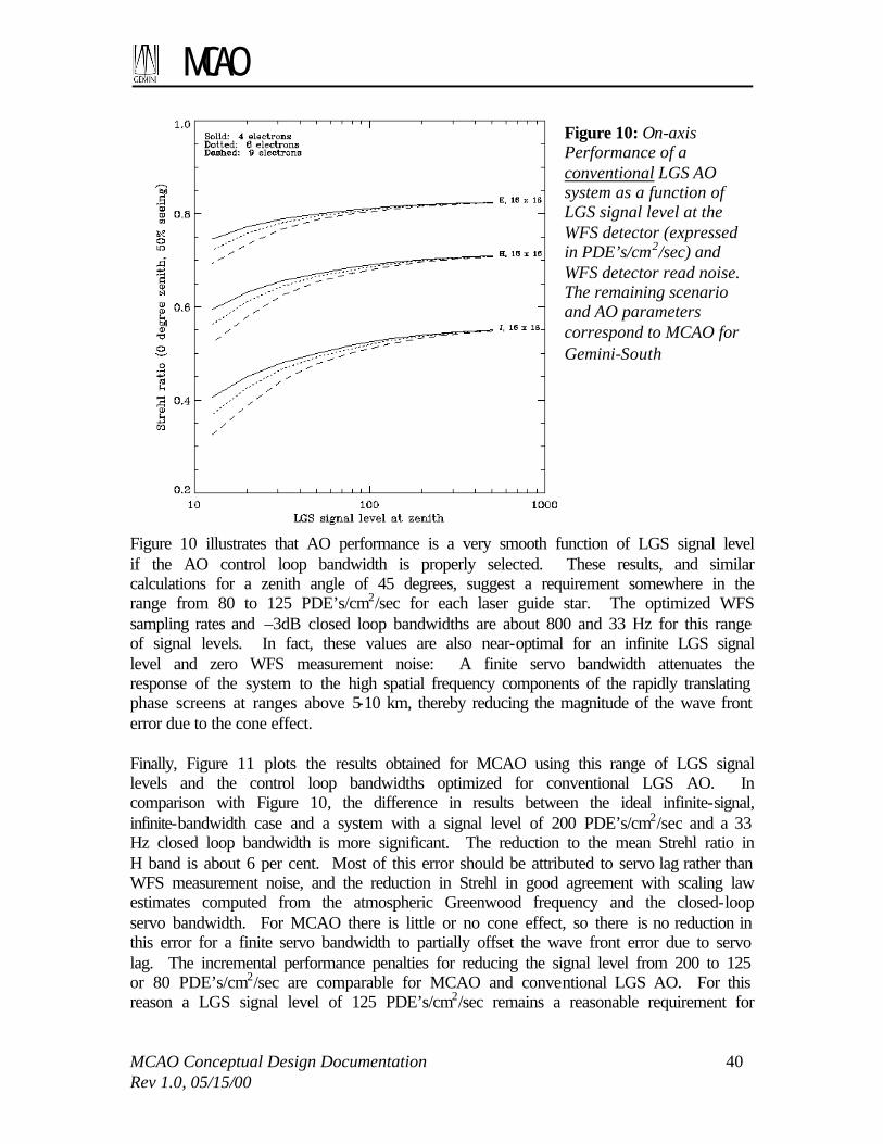
MCAO
MCAO Conceptual Design Documentation 40 Rev 1.0, 05/15/00
Figure 10 illustrates that AO performance is a very smooth function of LGS signal level if the AO control loop bandwidth is properly selected. These results, and similar calculations for a zenith angle of 45 degrees, suggest a requirement somewhere in the range from 80 to 125 PDE’s/cm2/sec for each laser guide star. The optimized WFS sampling rates and –3dB closed loop bandwidths are about 800 and 33 Hz for this range of signal levels. In fact, these values are also near-optimal for an infinite LGS signal level and zero WFS measurement noise: A finite servo bandwidth attenuates the response of the system to the high spatial frequency components of the rapidly translating phase screens at ranges above 5-10 km, thereby reducing the magnitude of the wave front error due to the cone effect. Finally, Figure 11 plots the results obtained for MCAO using this range of LGS signal levels and the control loop bandwidths optimized for conventional LGS AO. In comparison with Figure 10, the difference in results between the ideal infinite-signal, infinite-bandwidth case and a system with a signal level of 200 PDE’s/cm2/sec and a 33 Hz closed loop bandwidth is more significant. The reduction to the mean Strehl ratio in H band is about 6 per cent. Most of this error should be attributed to servo lag rather than WFS measurement noise, and the reduction in Strehl in good agreement with scaling law estimates computed from the atmospheric Greenwood frequency and the closed-loop servo bandwidth. For MCAO there is little or no cone effect, so there is no reduction in this error for a finite servo bandwidth to partially offset the wave front error due to servo lag. The incremental performance penalties for reducing the signal level from 200 to 125 or 80 PDE’s/cm2/sec are comparable for MCAO and conventional LGS AO. For this reason a LGS signal level of 125 PDE’s/cm2/sec remains a reasonable requirement for
Figure 10: On-axis Performance of a conventional LGS AO system as a function of LGS signal level at the WFS detector (expressed in PDE’s/cm2/sec) and WFS detector read noise. The remaining scenario and AO parameters correspond to MCAO for Gemini-South

MCAO
MCAO Conceptual Design Documentation 41 Rev 1.0, 05/15/00
MCAO, with 80 PDE’s/cm2/sec acceptable with some regrets. Section 5.2 relates these signal levels to the power requirements for the laser source itself.
At this point, there is still some risk and uncertainty in these requirements to be addressed during the preliminary design phase. The shape and size of the Shack-Hartmann spots on the LGS WFS focal plane need to be verified based upon final estimates for laser beam quality, performance of the BTO and LLT, the depth of the sodium layer, and the characteristics of the WFS lenslet and CCD arrays. Modest performance improvements may also be possible by tuning the temporal dynamics of the AO control law. We have tried to be conservative in the case of uncertainties, but will review and update our estimates as new information is obtained. 4.4 Natural Guide Star Modeling
4.4.1 Decoupling the LGS and NGS Control Loops
The error signal for the MCAO control loop consists of a combination of LGS and NGS WFS measurements. The NGS measurements are much fewer in number but have much more variable characteristics. The laser guide stars have fixed locations in the field and a nominally fixed, relatively low, level of measurement noise. The natural guide stars will have variable locations and signal-to-noise ratios for each observation. Evaluating NGS magnitude limits and sky coverage for MCAO would be difficult if the entire wave front reconstruction algorithm had to be reevaluated for each new science field. Implementing this approach in real time for actual observations would be even more difficult. These difficulties can be avoided by decoupling the NGS and LGS components of the AO control loop.
Figure 11: MCAO performance over a one arc minute square field of view as a function of LGS signal level. These results assume 6 read noise electrons for the LGS WFS CCD, median Cerro Pachon seeing, and a zero degree zenith angle.

MCAO
MCAO Conceptual Design Documentation 42 Rev 1.0, 05/15/00
Viewed abstractly, the relationship between the NGS and LGS measurements for MCAO is not very different from the situation in a conventional LGS AO system. The NGS measurements are necessary to correct a few low-order modes that are undetectable using the LGS, and the magnitude and location of the NGS varies for each observation. Current LGS AO systems implement two separate control loops driven by the LGS and NGS WFS measurements. To first order, the LGS-driven high-order loop is decoupled from the performance of the NGS tip/tilt loop by the use of a tilt-removed wave front reconstruction algorithm. The residual errors in the LGS loop do couple into the NGS loop (e.g., residual coma aberrations alias into the tip/tilt measurement for a quadrant or centroid detector), but the magnitude of this coupling is acceptable once the higher-order loop is closed. All of these comments are equally valid for MCAO, although (1) there is more flexibility in selecting the wave front modes to be controlled by the NGS loop, (2) there are also more options for conditioning the LGS control algorithm to decouple the higher-order control loop, and (3) modal control becomes more valuable for the NGS loop due to the greater variability between the modes to be controlled. Several approaches appear reasonable for items (1) and (2) above. Methods for selecting the NGS-controlled modes include:
(1a) Selecting global tip/tilt and the tilt anisoplanatism modes described in Section 4.2.2;
(1b) Computing a combined NGS/LGS reconstruction matrix, and selecting the columns of actuator commands which are driven by the NGS measurements.
The two approaches yield very similar sets of modes, and therefore virtually identical performance for the NGS loop as evaluated for several sample NGS constellations. Option (1a) reduces the work involved in computing a new MCAO control algorithm for each new field. The methods for decoupling the higher-order LGS loop from the NGS-controlled modes include:
(2a) Pre-processing the LGS WFS measurements to project off the influence of the NGS-controlled modes; or
(2b) Post-processing the actuator commands computed by the LGS wave front reconstruction algorithm to project off the NGS-controlled modes themselves.
Either of these approaches would be implemented by pre- or post-multiplying the coefficients of the LGS wave front reconstruction matrix by the appropriate projection, and therefore does not increase real-time computation requirements. These various options for decoupling the two control loops may differ in the degree to which residual higher-order errors alias into the NGS control loop. The amount of aliasing associated with approaches (1b) and (2b) has been evaluated and included in the system performance estimates in Table 6. See the appendices for a more analytic and precise description of the decoupling of the NGS and LGS control loops.
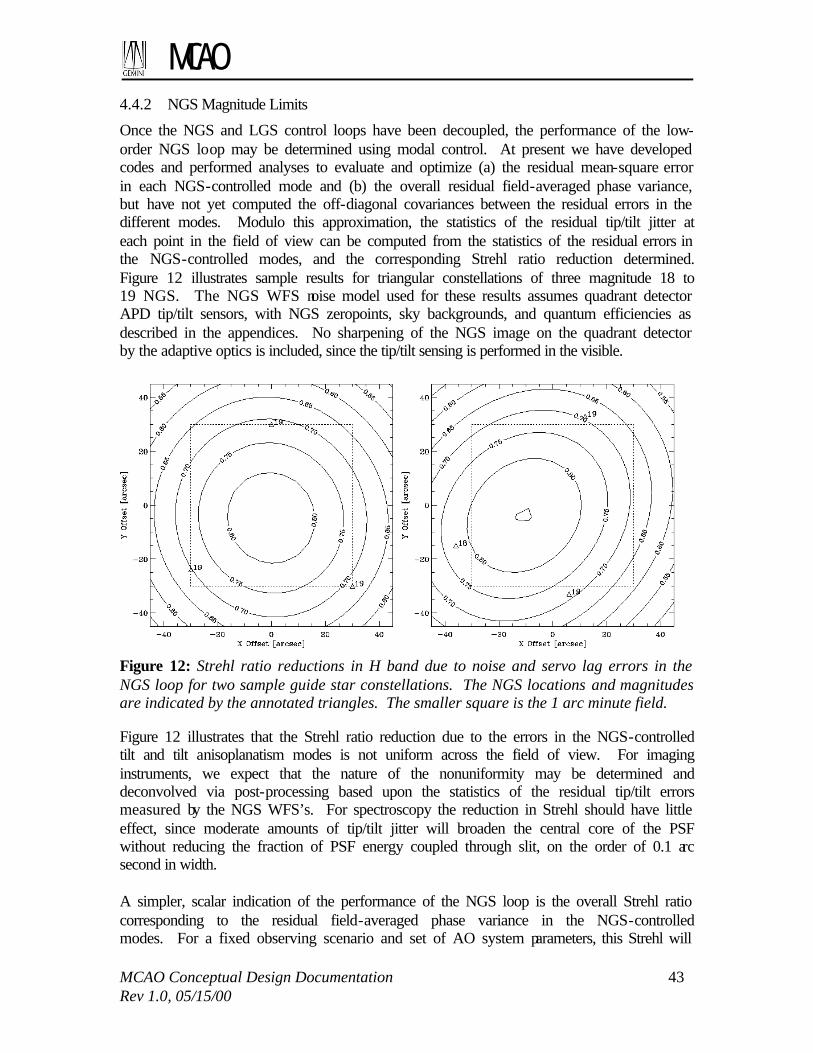
MCAO
MCAO Conceptual Design Documentation 43 Rev 1.0, 05/15/00
4.4.2 NGS Magnitude Limits
Once the NGS and LGS control loops have been decoupled, the performance of the low-order NGS loop may be determined using modal control. At present we have developed codes and performed analyses to evaluate and optimize (a) the residual mean-square error in each NGS-controlled mode and (b) the overall residual field-averaged phase variance, but have not yet computed the off-diagonal covariances between the residual errors in the different modes. Modulo this approximation, the statistics of the residual tip/tilt jitter at each point in the field of view can be computed from the statistics of the residual errors in the NGS-controlled modes, and the corresponding Strehl ratio reduction determined. Figure 12 illustrates sample results for triangular constellations of three magnitude 18 to 19 NGS. The NGS WFS noise model used for these results assumes quadrant detector APD tip/tilt sensors, with NGS zeropoints, sky backgrounds, and quantum efficiencies as described in the appendices. No sharpening of the NGS image on the quadrant detector by the adaptive optics is included, since the tip/tilt sensing is performed in the visible.
Figure 12: Strehl ratio reductions in H band due to noise and servo lag errors in the NGS loop for two sample guide star constellations. The NGS locations and magnitudes are indicated by the annotated triangles. The smaller square is the 1 arc minute field. Figure 12 illustrates that the Strehl ratio reduction due to the errors in the NGS-controlled tilt and tilt anisoplanatism modes is not uniform across the field of view. For imaging instruments, we expect that the nature of the nonuniformity may be determined and deconvolved via post-processing based upon the statistics of the residual tip/tilt errors measured by the NGS WFS’s. For spectroscopy the reduction in Strehl should have little effect, since moderate amounts of tip/tilt jitter will broaden the central core of the PSF without reducing the fraction of PSF energy coupled through slit, on the order of 0.1 arc second in width. A simpler, scalar indication of the performance of the NGS loop is the overall Strehl ratio corresponding to the residual field-averaged phase variance in the NGS-controlled modes. For a fixed observing scenario and set of AO system parameters, this Strehl will

MCAO
MCAO Conceptual Design Documentation 44 Rev 1.0, 05/15/00
be a function of (i) the magnitudes and locations of the three NGS, (ii) sky background, and (iii) the disturbance spectrum for windshake-induced tip/tilt jitter. A reasonable definition of the NGS magnitude limit for MCAO is the value yielding a field-averaged Strehl ratio reduction of 0.5 in H band. Figure 13 illustrates the field-averaged Strehl ratio in H band for the NGS loop with a sample NGS constellation and two different sets of values for sky background and telescope windshake. The NGS constellation consists of three stars of equal magnitude located at the corners of an equilateral triangle with base 0.87 arc seconds that is centered within the 1 square arc minute field-of-view. The limiting NGS magnitude is about 20.3 for the optimistic case of an 80% sky background (for Mauna Kea), and no windshake-induced jitter. The limiting magnitude falls to about 19.1 for the more representative case of a 50% sky background and the “typical windshake” disturbance spectrum specified for Gemini-North. MCAO does not appear to be dramatically more or less sensitive to these error sources than conventional LGS AO, but we will investigate the use of OIWFS or peripheral WFS tip/tilt measurements to reduce the effect of windshake. We will also revisit this subject as more accurate estimates/measurements of windshake at Cerro Pachon become available.
Finally, Figure 14 illustrates the effect of a less favorable constellation geometry on the NGS magnitude limits. Reducing the base of the equilateral triangle from 0.87 to 0.43 arc seconds degrades the magnitude limit from 19.1 to about 18.4. Displacing the equilateral triangle from the center to one side of the 1 arc minute field increases the limit by a further 0.2. Additional results illustrating the impact of the constellation geometry upon the performance of the NGS control loop are given in the appendix. Based upon these calculations, we have specified a limiting magnitude of 19 and a minimum triangle area of 0.25 square arc seconds (corresponding to an equilateral triangle with base 0.75 arc seconds) for the sky coverage estimates presented below in Section 4.4.4.
Figure 13: Field-averaged Strehl ratios in H band for the NGS loop as a function of NGS magnitude for median seeing, a 0 degree zenith angle, and a triangular guide star constellation with a base of 0.87 arc seconds. Solid: No windshake jitter, 80% sky background. Dashed: Typical Mauna Kea jitter, 50% sky background.

MCAO
MCAO Conceptual Design Documentation 45 Rev 1.0, 05/15/00
4.4.3 PSF Characteristics
The PSF can be formally split into two components: one corresponding to errors in the high order modes (servo lag and anisoplanatism errors for modes controlled by the system, fitting error for the modes not controlled by the system), and another corresponding to global image motion. The latter is exclusively related to the NGS-controlled modes described in section 4.4.1. The high order modes are the primary culprit for the well-known Core/Halo PSF shape. To first order for a Strehl ratio > 20%, the percentage of energy in the diffraction limited component of the image is equal to the Strehl ratio. For a telescope with a small central obstruction like Gemini, the fraction of energy in the central peak of a perfect diffraction pattern is 82%. The energy in a diaphragm of diameter 2 λ/D is 80% of the total energy in the diffraction image, and the energy in a diaphragm of diameter λ/D is 45%. These numbers, multiplied by the Strehl ratio of the actual short exposure images (determined by the high order LGS-controlled loop) can be used as guidelines in SNR estimations. The halo has characteristics that vary with wavelength and quality of compensation, noise, etc, and cannot be described simply in an analytical fashion. Its width varies between the seeing width and some fraction (0.25-0.3) of this quantity, being relatively smaller at shorter wavelengths. It is worth noting that in all the AO simulations carried out at Gemini, the halo seems to have a less detrimental effect than for actual images taken with lower order systems on 3.6-m telescopes. This may be because the contrast in width between halo and core is larger for an 8-m telescope, the diffraction limit being twice smaller. This increases the halo/core contrast by a factor of ~ 5. Also, the Strehl ratios planned for the CP MCAO system are slightly higher than those achieved with most AO the systems on smaller telescopes, increasing further this contrast.
Figure 14: Field-averaged Strehl ratios in H band for the NGS loop as a function of NGS magnitude for median seeing, a 0 degree zenith angle, 50% sky background, “typical” Mauna Kea windshake, and a triangular guide star constellation. Solid: centered triangle, 0.87 arc sec base. Dashed: centered triangle, 0.43 arc sec base. Dotted: displaced triangle, 0.43 arc sec base.

MCAO
MCAO Conceptual Design Documentation 46 Rev 1.0, 05/15/00
The stability of the high order PSF component is shown in Figure 6 and Figure 11. The spatial standard deviation of the Strehl ratio is given Table 12, and is of the order of 2.5% in H band at zenith for the MCAO baseline. These fluctuations are expected to be quite stable within +/- 1%, so that a first order correction on the photometry could achieve this level of accuracy.
Figure 15: Strehl ratio, FWHM, 50% encircled energy diameter and percentage of light
through a slit of 0.1” versus the distance to the central guide star.
The effect of the NGS-controlled modes on the image is solely to convolve the average high order PSF component by a 2-D gaussian profile. An example of the residual image motion is shown on Figure 6 of Appendix G; for 4 magnitude 19th stars, tip and tilt vary from approximately 10 mas to 16 mas within the central 1 square arcmin. It is important to note that this residual image motion will induce an elongation on the image, similar but smaller to what is observed in a one-star compensation system. The amplitude and direction of the elongation depends on location in the field, the relative brightness of the NGS, the location of the NGS, and the Cn
2(h) profile and wind profile. The PSF core broadening caused by the residual image motion does not throw energy very far into the halo wings, as is the case for the imperfectly compensated high order modes. For an equivalent reduction in Strehl, the effective loss in resolution, 50%

MCAO
MCAO Conceptual Design Documentation 47 Rev 1.0, 05/15/00
encircled energy, or slit throughput is therefore more benign. For instance, the 50% Strehl ratio loss that we adopt as an arbitrary criteria to estimate sky coverage is equivalent to a broadening of the time-averaged PSF by ~ 40 mas in H band, which increases the FWHM from 43 mas (diffraction limit) to 58 mas. The impact on the encircled energy depends on the exact wavelength. For spectrographs, however, whose pixel elements will probably not resolve the width of the diffraction core, this effect will be very moderate.
Figure 15 show an example of Strehl, FWHM, 50% encircled energy diameter and percentage of light coupled through a slit, versus the field position for a system equivalent to the Gemini baseline system (least square reconstructor, Monte-Carlo code). Figure 16 shows a log profile of a typical H band PSF. 4.4.3.1 Telescope and instrument
The telescope image quality specification is to deliver a static wave front that, after compensation by the adaptive optic system, will lead a Strehl of 0.8 at H. Performance is expected to be commensurate at other wavelengths. The specification for all instrument built to date is to deliver a Strehl of 0.8 at H. This includes all aberrations. It is
expected that most aberrations will be low order errors induced by misalignments. It is straightforward to compensate for these low order aberrations, as long as they are calibrated. Even field-dependent errors may be compensated using MCAO. Attention should be paid to making such calibration possible in future MCAO-optimized instruments. Given this, we have reduced the instrument contribution to the error budget from an H band Strehl of 0.8 to 0.95. Care should be taken in designing the instruments so that no significant chromatic aberration is not present, as it can not be compensated by the AO system. 4.4.4 Sky Coverage
MCAO sky coverage (SC) has been estimated using a Monte-Carlo code based on star counts taken from the Gemini model, which has been directly adapted from the Bahcall and Soneira model. Thousands of random fields were generated in the code, including stars from mR = 15 to 20. The potential NGS constellations were examined for each field. In particular, we computed the area defined by the 3 NGS potential candidates as the cross product V12⊗V13, where Vij is the vector separating guides stars i and j. The candidate constellation was validated if the norm of this product was over 1 square arcmin, or was over 0.5 square arcmin and the constellation bounded the field center. In all other cases, it was rejected. We allowed a slack of 15 arc seconds to center the science field on the instrument. In practice, this means that if no acceptable GS constellation is
Figure 16: H band PSF profile. For zenith and median seeing conditions

MCAO
MCAO Conceptual Design Documentation 48 Rev 1.0, 05/15/00
found, the case was re-examined with decentration of +/- 15 arc seconds in both R.A and dec. This implicitly assumes that at least 1 square arcmin FoV instruments are used, and that the object does not need to be absolutely centered (i.e. there is no image quality loss associated with this decentering). This code was run at two galactic latitudes and for various GS magnitudes. The latter were chosen to correspond to a Strehl loss of 50% with respect to the very bright star case presented earlier in this section. Results are given in Table 14. The same code was modified to allow a coherent comparison with Classical LGS AO (Table 13). For an arbitrary point in the sky, the TT error is split into two contributions: the noise error and the anisokinetism (TT anisoplanatism). We arbitrarily imposed equal weight to these two errors. This seems to be a reasonable criteria, since the sky coverage contribution from very bright stars at large angles and very faint stars nearby tends towards zero. The optimum may not be an exactly equal split of these two error contributions, but is not likely to be far from it. The criteria used for SC estimation for conventional LGS AO is the same as for MCAO: 50% Strehl ratio loss with respect to the Strehl obtained on-axis for very bright stars.
Sky C. at Gal. Pole
Sky C. at b=30o Limiting NGS magnitude
θmax
J 7% 21% 17.7 19” H 16% 44% 18.3 26” K 35% 74% 18.8 36”
Table 13: LGSO AO sky coverage at the galactic pole and 30 degrees galatic latitude, with assumptions for the value of the limiting magnitude and the maximum angle to the TT guide star. These results are for an AO system with one laser guide star and one Tip-Tilt natural guide star, and a 16x16 subapertures Shack-Hartmann system. The sky coverage values are for a Strehl ratio of 50% of the value that can be obtained on infinitely bright stars.
Sky C. at Gal. Pole
Sky C. at b=30o TT star magnitudes
J 12% 67% 18,19,19 H 14% 69% 19,19,19 K 24% 82% 19,20,20
Table 14: Gemini MCAO sky coverage values at the galactic pole and at 30 degrees galactic latitude. The assumptions for the magnitudes of the 3 required Tip-Tilt natural guide stars are given. The sky coverage is defined here as the fraction of the sky over which the Strehl loss is less than 50% with respect to the infinitely bright star case.
Overall, the sky coverage of AO and MCAO is comparable. AO has a slight advantage at longer wavelengths at high galactic latitude, but MCAO recovers it at shortest wavelengths and show a certain advantage at low galactic latitudes. In fact, the need for 3 GS with MCAO seems to be balanced by the fact that there is a significantly larger field of view to find these GS (2 arcmin) with respect to AO, where the search field is relatively smaller. This also explains why MCAO sky coverage seems less sensitive to the wavelength than for AO. This could be an interesting property, e.g. when spectral coverage (need for J band) is an important issue for the observing program.

MCAO
MCAO Conceptual Design Documentation 49 Rev 1.0, 05/15/00
Gal. latitude # HST pointings Status>0 [%] Status>0.5 [%] status>1 [%]
all 11953.0 72.5425 44.2399 32.2262 20-30 1573.00 83.0896 61.9835 43.8652 50-60 1547.00 61.8617 20.9438 9.56690 80-90 452.000 63.4956 17.6991 5.75221
Table 15: Sky coverage computed from HST pointings and USNO2 catalog for three 19th magnitude stars
In addition to this Monte-Carlo modeling, J.-P.Véran and D.Durand of the HIA have crossed HST pointing with the USNO 2 catalog to estimate the occurrence of having 3 GS of sufficient brightness and in an acceptable spatial configuration. The results are listed in Table 15. “Status” in this table is the surface area covered by the GS constellation in square arcmin, computed as the length of the cross product between the two vectors defined by the bright-to-dim guide source separations. These numbers are for a set of three guide stars of mR = 19, which correspond therefore to the H band sky coverage numbers given above. These numbers are not directly comparable to the numbers computed with the Monte-Carlo method, as here there no requirement on centering the constellation in the case of a 0.5 square arcmin GS “status”. One should expect the Monte-Carlo numbers to fall between the status=0.5 and status=1 numbers, and they approximately are. Overall, the numbers are consistent. Another interesting feature from the work done at HIA is that this computation included all HST pointings. If one assumes that the MCAO programs will on average point at target similarly distributed on the sky, Table 15 gives an average MCAO sky coverage on the order of 40%. 4.5 Summary
During the conceptual design phase we have performed extensive modeling of the MCAO system to establish the baseline first-order specifications for principal AO components and evaluate the resulting system performance. Certain parameters (order of wave front sensing and correction; DM mirror conjugate altitudes; corrected field-of-view) yield fairly soft performance tradeoffs that are not always suited to an explicit optimization of a quantitative performance metric. In these cases, baseline system parameters have been selected through a combination of simplified scaling laws, practical hardware and cost considerations, and qualitative judgment of what constitutes acceptable performance. Other parameters and issues (LGS signal level, NGS magnitude limits, PSF characteristics, sky coverage, and a practical control algorithm) are more crucial for MCAO and have received the most careful analysis of which we are capable. The results of these studies provide relatively firm values for the requirements and performance of a MCAO system as actually implemented on Gemini-South. Some of the findings of the system performance modeling effort include:
• MCAO performance is very uniform over a 1 square arc minute field, both in terms of Strehl ratios and more general PSF characteristics;

MCAO
MCAO Conceptual Design Documentation 50 Rev 1.0, 05/15/00
• The Strehl ratio degrades gracefully out of the 1 square arc minute central field. The useable field with Strehl ratio above 50% of the peak value is the full 2 are minute field in H and K band, and approximately 1.5 arc minute at J band.
• LGS signal level requirements are in the range of 80 to 125 PDE’s/cm2/sec at the WFS detector;
• Decoupled LGS/NGS control algorithms have been developed that are feasible in terms of evaluation and implementation; and
• NGS magnitude limits for MCAO correspond to very useful values of sky coverage, even when sky background noise and windshake jitter are taken into account.
We will continue to review and sharpen these performance estimates as more detailed information becomes available on parameters including laser beam quality, sodium column density, and windshake jitter at Gemini-South.
MCAO
MCAO Conceptual Design Documentation 51 Rev 1.0, 05/15/00
5 SUBSYSTEM DESIGN 5.1 Adaptive Optics Module
The Adaptive Optics Module (AOM) includes all of the optics, sensors, and diagnostics needed to compensate the input f/16 science beam and relay it to a science instrument at f/30. These components include the principal elements of the real-time MCAO control loop as described previously, namely 3 deformable mirrors, a tip/tilt mirror, 5 higher-order LGS wave front sensors, and 3 tip/tilt NGS wave front sensors. Additional components include atmospheric dispersion correctors (ADC’s) in the science path and the NGS WFS path, and three subsystems for WFS and DM calibration:
• Simulated natural- and laser guide stars located at the cassegrain focus near the entrance of the AOM. These simulated guide stars are used for (i) verification of optical alignment between AOM and science instruments, (ii) measurement of DM influence functions and DM-to-WFS alignment, and (iii) closed-loop tests of the MCAO control loop.
• Local reference sources to illuminate the LGS wave front sensors with known plane wave fronts and calibrate for lenslet-to-CCD misalignments and fabrication errors.
• An optional diagnostic, higher-order WFS used for wave front measurements of the three NGS source simulators. These measurements would be used tomographically to flatten the figures of the three deformable mirrors. This sensor effectively substitutes for the “DM interferometer” found in several existing AO systems. It could be eliminated if absolute alignment and position accuracy could be guaranteed for the AOM optics and DM actuators.
The AOM is mounted to the Gemini Instrument Support Structure (ISS). The maximum volume envelope is 2400 mm deep by 1500 mm wide by 1500 tall, and the mass limit is 900 kg. All service interfaces are through the ISS. All real-time-control electronics for the AO control loop must be packaged as part of the AOM. 5.1.1 Optical Design
The Adaptive Optical Module, consisting principally of an off-axis two-mirror relay transferring the f/16 cassegrain focus of the 8-meter telescope to a final instrument f/30 focus, contains various optical pick-offs to effect wave front correction and to monitor performance of the complete assembly. The complete optical design of the AO module consists of several sub-designs that serve joint or individual tasks. The Science Path through the module is nearly diffraction limited throughout the visible spectrum, and fully so for the infrared. The service paths that feed NGS and LGS inputs to their respective detectors are likewise nearly diffraction-limited. Special requirements beyond normal resolving power, such as precise mapping of the deformable mirrors onto Shack-Hartmann planes, are addressed and optimized.

MCAO
MCAO Conceptual Design Documentation 52 Rev 1.0, 05/15/00
5.1.1.1 Design Requirements
Top-level optical design requirements are summarized in Table 16. The requirements for the science path are taken or derived from the FPRD. For the NGS path, the requirements are selected to maximize sky coverage, which requires (i) a wide spectral passband and a high throughput to optimize the NGS magnitude limit, (ii) optical aberrations which are small relative to the residual turbulence-induced wave front errors under good seeing conditions, and (iii) the largest possible field-of-view to acquire guide stars. The field-of-view for the LGS WFS path matches the field size selected in Section 4.3.3 to obtain highly uniform AO performance across the compensated field-of-view. The remaining requirements for the LGS path are derived more from specific engineering considerations. Optical throughput must be as high as is feasible to minimize the required laser system power. The value for the maximum allowable pupil misregistration between the DM’s and the WFS is based upon a combination of simulation work and experience with existing AO systems. This limit must include design residuals, fabrication and alignment errors, and any dynamic misregistration induced by tip/tilt mirror adjustments or LGS jitter on the sky. Finally, any non-common path wave front errors in the LGS WFS path should be small enough to be compensated via calibration without saturating the linear dynamic range of the WFS. This limit is about 0.1 arc seconds for the expected width of the LGS Shack-Hartmann spots. It must include design residuals, fabrication and alignment errors, and the effect of LGS jitter on the sky. Parameter Science Path NGS WFS Path LGS WFS Path Spectral passband, µm
1.0-2.5 (5.0 goal) (0.85-2.5 or 5.0 with changeable dichroic)
0.45-1.00 0.589
Field-of-view radius, arc min
1 1 1 (width of square FOV) 90—200 km range
Wave front quality
Uncorrectable and non-common path errors of 60 nm (40 nm goal)
0.15 arc sec RMS spot size (0.10 goal)
Peak subaperture tilts less than 0.1 arc sec
Optical transmittance
0.75 0.7 0.7
Pupil imaging Worst case pupil motion of 3% on instrument cold stop
NA Worst case WFS-to-DM misregistration 10% of a subaperture width
Emissivity 19% NA NA Atmospheric dispersion at 45 degrees, arc sec
0.007, 0.85+/-0.07 µm 0.010, 1.25+/-0.1 µm 0.013, 1.65+/-0.1 µm 0.018, 2.20+/-0.2 µm
0.1 (0.05 goal)
NA
Table 16: AO Module Optical Design Requirements
5.1.1.2 Science Path
The Science Path in Figure 17, from which the NGS and LGS beams are picked-off by means of a beamsplitter, consists of two unequal focal length, eccentric pupil paraboloidal mirrors (OAP’s) that enclose three deformable mirrors (DM’s), and a final beamsplitter plate that transmits the Science Path while reflecting light to the WFS optics and detectors. For the current design, the first OAP forms conjugate images of

MCAO
MCAO Conceptual Design Documentation 53 Rev 1.0, 05/15/00
atmospheric planes at 8, 4 and 0 km onto DM2, DM1, and DM0, the latter being also conjugate to the image of the telescope’s secondary mirror, M2. This is in slight disagreement with the ranges of 9.0, 4.5, and 0 km selected based upon more recent analysis. Although the Telescope itself is a Ritchey-Chretien, the OAP’s introduce a small amount of coma and astigmatism over the circular one arc-minute radius field of view. The transmitting beamsplitter, BS1, is nominally 160 mm in diameter by 27 mm thick and is made from fused silica. It introduces under .005 waves of monochromatic aberration in the visible, and less in the infrared. It also produces a very small amount of chromatic lateral displacement, which can be completely corrected with a wedge angle of 1.8 arc minutes if desired. This wedge would also serve to reduce ghosting. Calcium fluoride may be used instead of fused silica to eliminate water absorption features and extend the spectral passband. We investigated the effect of using toroidal mirrors in place of OAP’s because the profiles of the two surfaces are so similar. Slight tip adjustments eliminate residual coma and produce an interesting candidate. However, the mapping on the image plane becomes distorted compared to the near perfection achieved with the OAP design, and in addition the focal plane is no longer truly perpendicular to the apparent optical axis. The OAP’s, despite their difficulty of fabrication, are warranted for this design. Preliminary estimates indicate the mirrors should be obtainable at prices on the order of $10,000 (uncoated). Figure 17, Figure 18, and Figure 19 show respectively the science path layout, geometric spot diagrams for the central 1 arc minute square field of view, and spot diagrams over the full 1 arc minute radius field of view. These figures do not include the science path ADC or its effect on image quality. The worst-case Strehl ratios at 1.65 microns over these two fields without the ADC are 0.988 and 0.960. The geometrical image quality in the NGS WFS path will be identical except for the variations introduced by the different ADC and beamsplitter.
Figure 17: Science path optical layout
Figure 18: Science path geometrical spot diagrams at the corners and edge of the central square 1 arc minute field of view

MCAO
MCAO Conceptual Design Documentation 54 Rev 1.0, 05/15/00
5.1.1.3 LGS Path and Field Corrector
The LGS path is more challenging. Five laser guide stars are symmetrically arranged in the field of view, one along the “axis”, the other four at angular distances of 42.5 arc-second in a cross-like pattern. While this pattern can be angularly rotated around the axis of the telescope, we have taken a worst-case orientation in which two of the stars appear at the upper and lower extremes of the meridional plane of symmetry Because the range to the laser guide stars
varies between 90 to 200 km, the images formed after the two OAP’s shift axially by as much as 638 mm from the Science Path focus. The shift from the nearest to the farthest LGS shifts the focal point by 350 mm. As might be expected, the telescope itself is no longer fully correct for spherical aberration and coma at these ranges, since the object is relatively near rather than at infinity. Additionally, the reflective relay composed of the two OAP’s shows different aberrations according to the conjugates at which it works. Additionally, its magnification changes with LGS range since it is a finite-conjugate relay whose conjugates are being disturbed. This causes a change in LGS plate scale, a change in exit pupil distance, a changing location of the image plane, and an unsymmetrical set of aberrations that are ever changing. We initially considered using trombone mirrors to place the LGS images at a fixed location. Given this, we found that a single aspheric glass lens, moving along with the trombone mirrors, could produce well-corrected LGS images for any range. Since one aspheric lens worked, we realized that two spherical lenses would do the same and be easier to fabricate. And given two spherical lenses, we recognized the possibility of moving them independently and achieving other goals, for example, holding the image plane fixed in space, thereby eliminating the need for the trombone mirrors. Unfortunately, the sharpness of image was insufficient with two “zooming” spherical lenses, so a third was added. This resolved the image sharpness, fixed image plane, and fixed plate scale objectives. The remaining issue was that the exit pupil shifted according to the motion of the preceding corrector lenses, forcing the WFS lenslet array plane to shift with LGS range. Although the individual collimators required to image the pupil onto the Shack-Hartmann plane could be fixed, the location of the SH planes and all additional optics on the way to the CCD arrays would have to move. So, we elected to add pupil-zooming optics to the corrector optics and fix the location of the exit pupil; indeed, to keep it telecentric at the intermediate focal plane regardless of the LGS range. This can be accomplished in principle by surrounding the image plane with two identical lenses disposed at equal distance from the intermediate focus. By symmetry, image magnification is held constant regardless of pupil zoom.
Figure 19: Science path geometrical spot diagrams at the center and edge of the full 1 arc minute radius
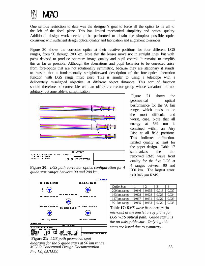
MCAO
MCAO Conceptual Design Documentation 55 Rev 1.0, 05/15/00
One serious restriction to date was the designer’s goal to force all the optics to lie all to the left of the focal plane. This has limited mechanical simplicity and optical quality. Additional design work needs to be performed to obtain the simplest possible optics consistent with sufficient design optical quality and fabrication and alignment tolerances. Figure 20 shows the corrector optics at their relative positions for four different LGS ranges, from 90 through 200 km. Note that the lenses move not in straight lines, but with paths devised to produce optimum image quality and pupil control. It remains to simplify this as far as possible. Although the aberrations and pupil behavior to be corrected arise from fore-optics that are not rotationally symmetric, because they are stationary it stands to reason that a fundamentally straightforward description of the fore-optics aberration function with LGS range must exist. This is similar to using a telescope with a deliberately misaligned objective, at different object distances. This sort of function should therefore be correctable with an off-axis corrector group whose variations are not arbitrary, but amenable to simplification.
Figure 21 shows the geometrical optical performance for the 90 km range, which tends to be the most difficult, and worst, case. Note that all energy at 589 nm is contained within an Airy Disc at all field positions. This indicates diffraction-limited quality at least for the paper design. Table 17 summarizes the tilt-removed RMS wave front quality for the five LGS at 4 ranges between 90 and 200 km. The largest error is 0.046 µm RMS.
Figure 20: LGS path corrector optics configuration for 4 guide star ranges between 90 and 200 km.
Figure 21: LGS path geometric spot diagrams for the 5 guide stars at 90 km range.
Table 17: RMS wave front errors (in microns) at the lenslet array plane for LGS WFS optical path. Guide star 3 is the on-axis guide star. Only 4 guide stars are listed due to symmetry.
Guide Star 1 2 3 4 200 km range 0.046 0.035 0.013 0.037 163 km range 0.028 0.028 0.028 0.024 127 km range 0.037 0.031 0.022 0.029 90 km range 0.035 0.032 0.020 0.035

MCAO
MCAO Conceptual Design Documentation 56 Rev 1.0, 05/15/00
5.1.1.4 LGS collimator and “De-Anamorphoser”
The output from the LGS field corrector consists of five small field points that are restricted by a field mask that has five perforations, each subtending 3 arc-seconds (the laser guide stars will be approximately 0.5-1.0 arc seconds in diameter at the sodium layer, but their images will be broadened because of atmospheric turbulence). The light emerging from the mask is substantially telecentric. It must be collimated, and a well-corrected pupil image formed on the Shack-Hartmann lenslet array with precisely the intended magnification factor. This pupil image should be “de-anamorphosed” to yield a circular image of DM0 in spite of the non-normal angle of incidence of the beams on this mirror, and thereby improve the registration between the DM actuators and the WFS subapertures. Five air-spaced doublets, whose focal lengths are slightly adjustable by changing the airspace, collimate the emerging light from the field mask. With apertures of just 10mm and focal length of 100mm, this ”zoom” produces only small variation in spherical aberration. Alternatively, a cemented doublet with an adjustable negative ”Barlow” element can provide a greater range of focal length adjustment with less aberration. The collimated rays constitute principal rays connecting the deformable mirror (DM0) and the SH plane; diffracted light then takes the nature of numerical aperture for this pupil-to-pupil image. The magnification between DM0 and the lenslet array plane is proportional to the focal length of the collimator, which is adjustable to correct small errors. Because the deformable mirrors are inclined 10-degrees relative to the optical axis, their projections on planes perpendicular to the axis are compressed by the cosine of 10-degrees. We correct this nominal error with a single cylindrical lens element, a solid Galilean telescope made from Schott BK7, 10mm in diameter, and 5.28mm thick, placed in the collimated beam following the collimator. As might be expected with such a small aperture and miniscule magnification, its aberrations are entirely negligible. The image of DM0 formed on the 16x16 Shack-Hartmann lenslet array is 8mm in diameter, with an individual lenslet width of 0.5 mm. Pupil distortion between DM0 and the lenslet array will degrade the performance and stability of the AO control loop by altering the DM-to-WFS influence matrix. In a LGS AO system, the feasibility of calibrating for this effect is complicated if the nature of the distortion changes with the range of the LGS. Based upon simulations and the performance of existing AO systems, the worst-case 1-axis pupil distortion should be kept to less than about 10% of a subaperture width, which must be allocated between the following error sources:
• Optical design residuals; • Optical fabrication errors; • Optical alignment errors; and • Beam wander due to LGS pointing error and tip/tilt mirror adjustments.
The last error listed will be dominated by the effect of tip/tilt mirror adjustments and is expected to be no more than 3% of a subaperture width (worse case) at DM0. The worst-

MCAO
MCAO Conceptual Design Documentation 57 Rev 1.0, 05/15/00
case optical design residuals are no more than about 5.5% of a subaperture width for pupil distortion, but are unacceptably large when the translation of the pupil with variations in LGS range is taken into account. The pupil mapping performance of the current design for the LGS optical path is summarized in Table 18.
Design exploration indicates that the self-imposed requirement that all elements of the corrector lens lie to the left of the intermediate focal plane (which optimizes image quality at a flat focal surface) is limiting our ability to reduce the pupil motion. Since diffraction-limited image quality is not required at the focal plane we will modify the optical design by allowing a lens to lie to the right of the intermediate focus. With the large f-numbers involved, the main aberration at the intermediate image will be field curvature, for which the obvious solution is a curved mask. We expect to reduce the amount of pupil motion by at least a factor of two, which will be sufficient. The actual wave front sensors for the five LGS will be implemented using either 1 or 5 lenslet arrays and associated CCD arrays. The packaging with 5 lenslet arrays should be straightforward with an optical path of about 90 mm between the intermediate focal surface and the collimators. Figure 22 illustrates how the pupils from all five guide stars could be combined on a single sensor. Four rhomboidal prisms are used to reposition the separate collimator axes very close together. The rhombs could in principal have semi-circular output apertures that actually allow the five beams to touch, but we have assumed a separation of one millimeter between all 8mm beams. This additional spacing is consistent with placing all 5 sets of Hartmann spots on a single CCD array of 1282
pixels. Transmission by the rhombs is 100% except for two air-glass reflections, and internal absorption is insignificant in Schott BK7 glass. Because the central beam has a shorter path to the SH lenslets, it may be necessary to add a field lens to ensure that the exit pupil of the telescope falls at the same longitudinal distance as the other four paths. This can be done with a singlet if the focal length of the collimator is appropriately adjusted.
Table 18: Worst-case 1-axis pupil mapping errors between DM0 and the lenslet array expressed in terms of per cent of a subaperture width. Only 4 guide stars are listed due to symmetry. The “overall” distortion value is increased by translation of the pupil image with LGS range
Guide Star 1 2 3 4 200 km range 2.18 3.90 4.92 2.88 163 km range 2.18 3.40 4.80 4.83 127 km range 2.16 2.84 4.86 5.04 90 km range 2.10 2.26 5.08 5.42 Over all ranges 4.18 4.02 13.36 8.28

MCAO
MCAO Conceptual Design Documentation 58 Rev 1.0, 05/15/00
Figure 22: Concept for combining all 5 LGS beams on a single lenslet array
5.1.1.5 NGS WFS Path and NGS/LGS Beamsplitter
The optical design characteristics of the NGS WFS path are identical to the science path apart from the ADC and beamsplitting elements. As described in Section 5.1.2, three quadrant detector tip-tilt sensors and possibly a diagnostic higher-order wave front sensor are placed behind the NGS focal plane. The NGS and LGS paths are split after both have been separated from the science path. The LGS and NGS return signals are separated spectrally, since the use of movable pickoff mirrors for the NGS path would result in significant vignetting of the LGS beams. Throughput to the LGS WFS at 0.589 µm must be maximized to reduce laser power requirements, and average throughput to the NGS WFS over the 0.45-1.0 µm passband must be maximized to improve NGS magnitude limits and maximize sky coverage. Values of 0.99 and 0.95 for beamsplitter throughput have been used in the end-to-end transmittance calculations presented in Section 5.1.1.6. Just as importantly, leakage of the LGS signal into the NGS WFS must be minimized. At Zenith, the defocused image of a LGS on the NGS focal plane covers a region of about 260 square arc seconds. The unfiltered background level is equivalent to about magnitude 16 per square arc second for the LGS signal levels and NGS zeropoints used here. At a zenith angle of 45 degrees the area is reduced to 130 square arc seconds, but the background level increases to about magnitude 15.5. The dark sky background corresponds to about magnitude 21.5 per square arc second. The required attenuation of the LGS signal into the NGS optical path is consequently about 22.5-15.5=7 magnitudes, or a factor of about 625-1.

MCAO
MCAO Conceptual Design Documentation 59 Rev 1.0, 05/15/00
The above specifications for throughput and extinction can be achieved using Rugate filters. The average throughput over the 0.45-1.0 µm NGS passband can be as high as about 0.94 if the 0.589 µm light is reflected, and the extinction requirement is also significantly exceeded. We have not yet verified that Rugate filters are a feasible option in terms of their sensitivities to variations in temperature and angle of incidence. The best extinction possible using a more conventional multi-layer dielectric coatings is about 50- or 100-1, which would degrade sky coverage by increasing the sky background to about magnitude 19.5 per square arc second over about 0.36 square arc minutes of the guide field. In this case, smaller laser line rejection filters might be placed immediately before each NGS tip/tilt sensor. As with the Science Path, it may be desirable to fabricate the beamsplitter with a slight wedge to eliminate a small amount of lateral chromatic displacement. 5.1.1.6 Transmittance Calculations
This section summarizes the predicted transmittance for the LGS and NGS WFS paths. See Table 9 in Section 3.2.2 for the Science Path transmittance estimates. The NGS tip/tilt sensor path in the AOM includes 10 ordinary mirror reflections, one reflection off the science beamsplitter, and a transmission through the LGS/NGS beamsplitter. The NGS tip/tilt sensor proper includes one lens, one pyramid mirror reflection, and one fiber-air interface. Both Rugate and more conventional dielectric coatings have been considered for the LGS/NGS beamsplitter. The transmittance calculations are summarized in Table 19. It appears that the specified throughput of 0.7 can be met for red stars using the Rugate filter. For the dielectric coating there is a relative transmittance loss of about 10 per cent. Wavelength
500 nm 700 nm
Transmission per reflection 0.944 0.979 10 reflections 0.562 0.809 Science beamsplitter, net 0.990 0.995 NGS/LGS Rugate BS 0.950 0.950 NGS/LGS dielectric BS 0.850 0.850 Air-glass per surface 0.9925 0.996 ADC net (4 surfaces) 0.970 0.984 Lenses 0.977 0.988 Pyramid mirror 0.944 0.979 Total transmission
With Rugate BS 0.473 0.728 With dielectric BS 0.402 0.651
Table 19: Transmittance estimates for the NGS WFS optical path
The LGS path contains 8 mirror reflections, 1 science beamsplitter reflection, a 5-element corrector lens, 1 collimator, 1 anamorphoser lens, 1 rhombic fold prism, 1 SH lenslet, and a 4- or 6-element transfer relay between SH lenslet and CCD. Table 20 summarizes the optical transmittance calculation for these elements. The estimated transmittance is about

MCAO
MCAO Conceptual Design Documentation 60 Rev 1.0, 05/15/00
3.5 per cent (relative) less than the factor of 0.7 that has been used to estimate laser power requirements. Wavelength 589nm Transmission per mirror reflection 0.962 8 reflections 0.730 Science Beamsplitter net 0.993 NGS/LGS Rugate beamsplitter 0.990 NGS/LGS dichroic beamsplitter 0.850 Air-glass per surface optimized 589nm 0.998 5 element Lens Corrector 0.980 Collimator 0.996 Anamorphoser lens 0.996 Rhombic combiner prism 0.996 Shack-Hartmann Lens 0.996 6-element SH-CCD relay lenses 0.976 Total Transmission
With Rugate BS, w/o ADC 0.676 With dichroic BS, w/o ADC 0.580
Table 20: Transmittance estimate for the LGS WFS optical path
5.1.1.7 Fabricability
The overall optical performance specification for the MCAO system includes 60 nm RMS wave front error for non-common path and uncorrectable wave front errors in the AO module. Splitting this equally (in quadrature) between the Science and LGS WFS paths yields about 42 nm RMS for each, or about 0.08 waves RMS at 0.546 microns. The RSS sum of uncorrectable optical design errors, component fabrication errors, and alignment errors must fall below this specification. There are a total of 3 fold mirrors, 2 OAP’s, 3 DM’s, and 1 transmissive beamsplitter in the science path. Additionally, in the LGS path there are 5 corrector lens elements, followed by 2 collimator lenses, 1 de-anamorphoser lens, the Shack-Hartmann lenslets, and a relay to transfer the image to the CCD array. It is apparent that the optical components must be made to comparatively high quality, a task complicated because certain elements are used “off axis” and tipped. Fabrication of flat- and spherical-surfaced refractive elements is straightforward and very stringent tolerances can be achieved at modest cost. Optical glass and crystal calcium fluoride is routinely produced to extremely high homogeneity and with low birefringence, and likewise poses no technical obstacle. For such components, thickness tolerances of 0.050mm, wedge errors of 0.2 arc-minutes, flatness/sphericity errors of quarter wave P-V, and radius of curvature errors of 0.1% are anticipated. “Melt Data” provided by the glass vendor gives accurately measured refractive index values. These, along with precisely measured radii and thickness values of the finished elements enable a final computer-aided design optimization using air spaces and lens tilt/decentrations as variables.

MCAO
MCAO Conceptual Design Documentation 61 Rev 1.0, 05/15/00
The OAP’s pose the more difficult task. They come from parent paraboloids that are respectively 1.1 and 3.7 meters in diameter, the latter being f/0.67! Clearly they will be made with direct-grinding and direct-figuring techniques over their modest apertures. It has been suggested that one of several possibilities will be to first make the appropriate close-fitting toroidal mirror, with circular cross sections, and then locally figure this with optical NC machinery (Brashears, Tinsley), or with ion beams (Kodak). The toroids fit the paraboloids to within just a few wavelengths of visible light. The figure accuracy of the mirrors must be twice that of their allowable contributions to the wave front budget, or about 1/8 wave P-V at 633nm, producing quarter wave phase errors. While difficult, this is within the state of the art. Testing of the mirrors is straightforward; in the most obvious case, they remain sections of true paraboloids, and as such can be tested in autocollimation against a flat mirror. Prospective vendors may elect to use other methods. Note that the radii and focal lengths of the OAP’s can be loosely toleranced, affecting principally the plate scale in proportion to the percentage errors of the focal lengths. While the radii do affect pupil magnification and the location of additional instrument focal planes (laser guide star images in particular), errors in the pupil magnification are already anticipated and adjustable in those optical paths. Their effects on aberration are negligible, since they form a collimator/camera pair each of whose mirrors are used at null conjugates, regardless of individual focal lengths. Alignment of OAP’s is amenable to logic; decentration, tilt, and rotation enable any such mirror to be rapidly and unambiguously adjusted. The mirrors will be marked on the edge and rear surface, and perhaps at the mechanical center of the mirror section, as an aid to initial positioning. An alignment telescope enables the center of the mirror to be positioned according to requirements (not critical except to insure freedom from vignetting), and once there tilt and rotation adjustments enable the meridian to be established and the astigmatism-free axis put in place to diffraction-limited accuracy. Because the space between the OAP’s is collimated, little harm is done if the spacing is incorrect as may occur with the complicated package consisting of three deformable mirrors (DM’s) with tilts and positions that may be in error. Ideally there will be an alignment fixture fore each such mirror so that the line-of-sight telescope can be used to center each in the optical path 5.1.2 Sensors
This section describes the design trades, design concepts, and first-order performance characteristics for the laser- and natural guide star wave front sensors in the AOM. See Sections 5.1.1.6 and 5.4.4.7.4 for discussions of optical transmittance and electronics interfaces, respectively.
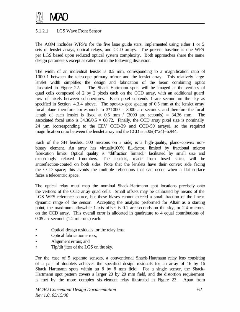
MCAO
MCAO Conceptual Design Documentation 62 Rev 1.0, 05/15/00
5.1.2.1 LGS Wave Front Sensor
The AOM includes WFS’s for the five laser guide stars, implemented using either 1 or 5 sets of lenslet arrays, optical relays, and CCD arrays. The present baseline is one WFS per LGS based upon reduced optical system complexity. Both approaches share the same design parameters except as called out in the following discussion. The width of an individual lenslet is 0.5 mm, corresponding to a magnification ratio of 1000-1 between the telescope primary mirror and the lenslet array. This relatively large lenslet width simplifies the design and fabrication of the beam combining optics illustrated in Figure 22. The Shack-Hartmann spots will be imaged at the vertices of quad cells composed of 2 by 2 pixels each on the CCD array, with an additional guard row of pixels between subapertures. Each pixel subtends 1 arc second on the sky as specified in Section 4.3.4 above. The spot-to-spot spacing of 0.5 mm at the lenslet array focal plane therefore corresponds to 3*1000 = 3000 arc seconds, and therefore the focal length of each lenslet is fixed at 0.5 mm / (3000 arc seconds) = 34.36 mm. The associated focal ratio is 34.36/0.5 = 68.72. Finally, the CCD array pixel size is nominally 24 µm (corresponding to the EEV CCD-39 and CCD-50 arrays), so the required magnification ratio between the lenslet array and the CCD is 500/(3*24)=6.944. Each of the SH lenslets, 500 microns on a side, is a high-quality, plano-convex non-binary element. An array has virtually100% fill-factor, limited by fractional micron fabrication limits. Optical quality is “diffraction limited,” facilitated by small size and exceedingly relaxed f-numbers. The lenslets, made from fused silica, will be antireflection-coated on both sides. Note that the lenslets have their convex side facing the CCD space; this avoids the multiple reflections that can occur when a flat surface faces a telecentric space. The optical relay must map the nominal Shack-Hartmann spot locations precisely onto the vertices of the CCD array quad cells. Small offsets may be calibrated by means of the LGS WFS reference source, but these biases cannot exceed a small fraction of the linear dynamic range of the sensor. Accepting the analysis performed for Altair as a starting point, the maximum allowable 1-axis offset is 0.1 arc seconds on the sky, or 2.4 microns on the CCD array. This overall error is allocated in quadrature to 4 equal contributions of 0.05 arc seconds (1.2 microns) each: • Optical design residuals for the relay lens; • Optical fabrication errors; • Alignment errors; and • Tip/tilt jitter of the LGS on the sky. For the case of 5 separate sensors, a conventional Shack-Hartmann relay lens consisting of a pair of doublets achieves the specified design residuals for an array of 16 by 16 Shack Hartmann spots within an 8 by 8 mm field. For a single sensor, the Shack-Hartmann spot pattern covers a larger 20 by 20 mm field, and the distortion requirement is met by the more complex six-element relay illustrated in Figure 23. Apart from

MCAO
MCAO Conceptual Design Documentation 63 Rev 1.0, 05/15/00
distortion, the image quality for either design is fully diffraction limited due to the slow f-ratios.
The candidate CCD array for the case of 5 separate sensors is the EEV CCD-39 with 80 by 80 pixels and 4 output amplifiers. A read rate of 1 megapixel/second/port enables the illuminated portion of the array to be read out in less than the required 1 millisecond, and is consistent with the specification for 6 read noise electrons. For a single sensor, the same performance can be achieved using the CCD-50 chip with 128 by 128 pixels and 16 output amplifiers. The quantum efficiency requirement of 0.85 at 0.589 µm given in Section 3 is also met.
5.1.2.2 NGS Tip/Tilt Wave Front Sensor
The AOM includes three tip/tilt NGS WFS for use with stars as dim as 20th magnitude. For this reason, the design concept is a quadrant detector with 4 fiber-fed APD photon-counting detectors. An optical pyramid in the focal plane of the NGS path defines the quadrant detector, and a lens immediately before the pyramid forms images of the pupil on the entrance of each fiber leading to the APD’s. The field of view of the sensor is limited to 1 square arc second to minimize sky background noise. This field stop may be adjustable for initial acquisition, and to minimize background further under very good seeing conditions as well. Each tip/tilt NGS must patrol at least half of the focal plane to acquire guide stars. Positioning accuracy of 0.02 arc seconds on the sky is required, since the linear dynamic range of the sensor may be as small as 0.15-0.2 arc seconds when the visible image of the NGS is partially sharpened by the AO under good seeing conditions. This corresponds to a positioning accuracy of 23 µm in the NGS focal plane. The WFS probe arms must be controlled in tilt as well as translation to maintain pupil alignment on the optical fibers, but this requirement will be reviewed. Atmospheric dispersion compensation is required, since the magnitude of dispersion across the 0.45-1.0 µm passband is about 1.4 arc seconds at a zenith angle of 45 degrees. The specified level of compensation is 0.05-0.10 arc seconds, again chosen not to compromise performance under good seeing conditions. The correction may be implemented with either a single ADC 15 cm in diameter, or three much smaller ADC’s
Figure 23: Shack-Hartmann spot relay lens for 5 LGS pupils on a single lenslet array

MCAO
MCAO Conceptual Design Documentation 64 Rev 1.0, 05/15/00
mounted on the probe arms themselves. In this second case any apparent differential image motion caused by adjusting the ADC angle must be calibrated. Finally, at least one of the tip/tilt NGS will be equipped with a ND filter wheel (or a manual filter holder) to enable calibration and testing on relatively bright stars. 5.1.2.3 NGS Diagnostic Higher-Order Wave Front Sensor
If included, the purpose of this optional diagnostic sensor is to flatten all three deformable mirrors and achieve satisfactory optical performance across the full field of view of the instrument. It essentially substitutes for the “DM interferometer” found in several existing AO systems. The sensor would be used for higher-order wave front measurements of the three NGS source simulators. These measurements would be combined tomographically with an on-axis wave front measurement from the Gemini high-resolution WFS (HR WFS) to determine the figure adjustments required for the three DM’s. DM edge actuators will be monitored as well, since the only aperture stops in the path will be the deformable mirrors themselves. The design concept for this sensor is the Gemini HR WFS, a similar diagnostic sensor. It would include a 16 by 16 or 20 by 20 lenslet array, a Photometrics-like camera with a 1k by 1k pixel CCD, and would use existing software to reconstruct wave fronts from well-sampled, low noise Hartmann data. The sensor head must be mounted on a probe arm for wave front measurements of the three NGS source simulators, but access to general field points is not required. 5.1.3 Deformable and Tip/Tilt Mirrors
Continuous facesheet, stacked actuator deformable mirrors have been assumed for MCAO due to the order of correction that is required. The three deformable mirrors are optically conjugate to ranges of 0, 4.0-4.5, and 8.0-9.0 km, and the larger values are assumed for now to determine the required clear apertures and numbers of actuators. The three mirrors will have 17, 17, and 9 actuators across the diameter of the collimated 84 mm beam, yielding inter-actuator spacings of 5.4, 5.4, and 10.8 mm. Each mirror includes rings of guard actuators to provide uniform influence functions for the actively controlled actuators. The sizing for the two mirrors conjugate to 4.0-4.5 and 8.0-9.0 km must also account for the 2 arc minute diameter field-of-view. These considerations yield the following actuator geometries for each mirror: • DM 0 at h=0 km: 241 actively controlled actuators in a 17 by 17 array, within a 21
by 21 array of 349 total actuators. This provides 2 full guard rings around the pupil. • DM 1 at h=4.5 km: 352 actively controlled actuators in a 20 by 20 array, within a 24
by 24 array of about 468 total actuators. This provides 2 guard rings for all field points within a circular 1.15 arc minute field. For field points at the corners of the fully corrected square 1 arc minute field, the minimum separation between the edge of the beamprint and the outer ring of guard actuators is 1.65 times the inter-actuator spacing. The corresponding value at the edge of the full 2 arc minute field is 0.88.

MCAO
MCAO Conceptual Design Documentation 65 Rev 1.0, 05/15/00
• DM 2 at h=9.0 km: 145 actively controlled actuators in a 13 by 13 array, within a 17 by 17 array of 241 total actuators. This provides 2 full guard rings for all field points in the 2 arc minute field of view.
These values have been used for the purposes of packaging the optical design and determining real-time signal processing requirements. The actuator stroke requirement is 4 µm, derived from the performance of existing DM’s and an RMS optical path difference of 1.12 µm for a worst-case r0 of 10 cm. Actuator uniformity and repeatability must be sufficient to enable unobservable mirror modes to be monitored without the use of an interferometer. These modes include piston, waffle, and the combinations of quadratic modes on multiple mirrors that induce tilt anisoplanatism. The tolerance on the latter modes for a place scale change of 30 parts per million is 15 nm peak-to-valley in each quadratic mode. This level of calibration must be maintained over the full range of operating temperatures. Finally, the requirements on hysteresis are thought to be similar to a conventional AO system, but this effect has not yet been included in simulations. See Section 5.4.4.7.4 for a discussion of DM electronics interfaces. The possible options for the tip/tilt mirror are the two off-axis parabolas located before and after the deformable mirrors. The conjugate ranges for these mirrors are about 13 and –3km. Tilt adjustments on the former mirror will translate the image of the primary on the WFS pupil and vary the illuminated regions of the edge subapertures. An equal tilt on the second parabola will introduce less pupil motion at the WFS, but will shift the DM-to-WFS registration. The magnitude of these shifts has been estimated from the values for (a) the RMS 1-axis tip/tilt jitter for average seeing, 0.14 arc second, and (b) the RMS 1-axis jitter of 0.13 arc second predicted for windshake under typical conditions. The combined RMS jitter is about 0.2 arc seconds, and the beamprint translations associated with a peak jitter of 1.0 arc seconds are as follows: • OAP 1: Illumination shifts by 0.13 of a subaperture at the WFS • OAP 2: Illumination shifts by 0.03 of a subaperture. Beamprints translate by 0.03,
0.07, and 0.05 of an inter-actuator spacing on the three DM’s. The second option is our preferred approach at this time, and the beamprint translations are included in the overall budget for DM-to-WFS misalignment. These calculations will be revisited once data from the fast tip/tilt loop on Gemini-North becomes available. The effect of offloading tilt to the secondary mirror will also be modeled. The dynamic range requirement for the tip/tilt mirror is +/-200 arc seconds (TBR), which corresponds to about +/-2 arc seconds in output space. The closed loop bandwidth requirement is 300 Hz and has been taken from Altair. The clear aperture is about 10.2 cm for OAP 2. These values are consistent with the performance of existing tip/tilt mirrors.

MCAO
MCAO Conceptual Design Documentation 66 Rev 1.0, 05/15/00
5.1.4 Artificial Sources
The AOM includes two sets of multiple artificial sources used for calibration and diagnostic purposes. One or several Collimated reference sources are used to illuminate the LGS wave front sensors with known plane wave fronts to calibrate for optical misalignments and fabrication errors between the Shack-Hartmann lenslet array(s) and the CCD array(s). These sources are accessed by means of a flip mirror (or mirrors) located after the LGS WFS collimator lenses. These sources need not match the 0.589 µm laser wavelength precisely. They should be unresolved by a single WFS lenslet. If these sources are adjustable in translation they may be used to measure the tilt transfer function of each WFS subaperture for an ideal point source, which in turn can be used to focus the Hartmann spots on the WFS detector array. The requirement for these sources can be removed if the required alignment accuracy and stability of the of the WFS optics and CCD array(s) can be achieved passively Secondly, a simulated array of 3 natural and 5 laser guide stars is located at the telescope cassegrain focus near the entrance of the AOM. These simulated guide stars are used for (i) daytime verification of optical alignment between the OIWFS and the AOM, (ii) measurement of DM influence functions and DM-to-WFS alignment, (iii) daytime tests of the MCAO control loop. Note that both visible and IR NGS sources will be necessary for (i) and (iii). The simulated LGS and the NGS sources must be usable simultaneously to close the AO loop using the LGS WFS while measuring performance at the science instrument. The LGS sources must be matched to the narrow spectral passband of the LGS WFS. The NGS sources should be white light sources and must be unresolved at 1 micron. An array of pinholes would be suitable for the three NGS sources, and the LGS sources could be inserted using fibers. 5.1.5 Mechanical Packaging Concepts
Figure 24 from the feasibility design report illustrates the mechanical packaging concept developed for the Science Path optical design. The Science Path optics are mounted in-plane within a rigid optical bench attached to the telescope Instrument Support Structure (ISS) at cassegrain focus. The electronics are enclosed within two Gemini standard racks located at the back end of the instrument and supported by a separate frame. The volume envelope allowed for a Gemini ISS-mounted instrument is 2100 mm deep by 1500 mm wide by 1500 mm tall. The space available for optics and mechanisms is about 1240 by 1500 by 1500 mm with the electronics cabinets arranged as in Figure 24. At this point, we have developed folded optical layouts for the NGS and LGS WFS paths to assess the feasibility of this packaging approach. Two sets of layouts have been developed, corresponding to the choices of transmitting or reflecting the LGS path at the LGS/NGS beamsplitter. The science path is identical for the two cases and is illustrated in side view in Figure 25. This figure illustrates the location of the science path ADC that is not yet incorporated in the design, and also the location of the f/30 focal plane relayed to a second instrument mounted on the ISS. Figure 26 and Figure 27 are layouts for the LGS and NGS WFS optical paths with the LGS path reflected off the NGS/LGS beamsplitter. This is expected to be the preferred

MCAO
MCAO Conceptual Design Documentation 67 Rev 1.0, 05/15/00
configuration for maximizing optical throughput to the NGS WFS with a Rugate filter. In Figure 26, the LGS WFS optical path is folded down with the LGS WFS camera(s) (not shown) mounted at the bottom of the instrument. Figure 27 is a top-down view of the NGS path, which is folded out-of-plane from the rest of the optical system towards the side of the AO module. Two possible locations for the NGS ADC are also illustrated. In this configuration, the other side of the AO module is available to mount DM high voltage amplifiers, LGS WFS camera digitizers, or other electronics that should be located close to the associated hardware. The depth of the optical layout from the
face of the ISS to the back surface of the NGS path folds is about 1190 mm, approximately 50 mm within the target envelope. Figure 28 and Figure 29 illustrate the LGS and NGS paths with the LGS path transmitted through the LGS/NGS beamsplitter. In this case there is more clearance underneath the LGS correcting lens for the WFS camera(s), but the NGS path must be folded again and brought through to the other side of the instrument. Figure 30 is a side-view of the NGS path to demonstrate that the path passes between the DM’s and OAP in the science path.
Figure 25: Side view of science optical path folded to fit within mechanical design envelope
Figure 26: Side view of LGS optical layout with LGS path reflected off the LGS/NGS beamsplitter
Figure 24: Mechanical design concept for mounting the MCAO AOM to the Instrument Support Structure

MCAO
MCAO Conceptual Design Documentation 68 Rev 1.0, 05/15/00
Figure 27: Top view of NGS optical path with the NGS path transmitted through the LGS/NGS beamsplitter
Figure 28: Side view of LGS optical layout with LGS path transmitted through the LGS/NGS beamsplitter
Figure 29: Top view of NGS optical path with the NGS path reflected off the LGS/NGS beamsplitter
Figure 30: Side view of NGS optical path with the NGS path reflected off the NGS/LGS beamsplitter

MCAO
MCAO Conceptual Design Documentation 69 Rev 1.0, 05/15/00
5.2 Laser System
The Laser System is the subsystem of the Laser Guide Star system and includes all components, both hardware and software, necessary to produce and maintain 5 laser beams at the sodium wavelength. These components are one or multiple laser heads and laser enclosures, the laser electronics, a control system, cooling systems, and any diagnostics that are needed to maintain the production of the sodium light. The Laser System requirements are presented in section 5.2.1, and possible candidate laser technologies are described in section 5.2.2. Since the sodium laser power required for routine MCAO observations has not been demonstrated to date, section 5.2.3 presents the laser development plan undertaken by Gemini to enable the procurement of a Laser System in the MCAO program time-scale.
5.2.1 Requirements
5.2.1.1 Laser power requirement
Zenith angle θ = 0 and 45 degrees
Laser wavelength λ = 0.589 µm
Laser beam quality < 1.5 times diffraction-limited
BTO transmission TBTO = 0.8 if the laser system head is mounted on the telescope center section, TBTO = 0.6 if it is located in the telescope pier
LLT transmission TLLT = 0.9
LLT pupil diameter DLLT = 450 mm
Beam diameter on LLT primary mirror Dlaser = 300 mm @1/e2 intensity points
Atmospheric transmission (one-way) at zenith Tatmo = 0.8
Median seeing conditions r0 = 20.2 cm @ 0.589 µm
Low-to-average sodium column density CS = 2 109 - 3 109 atoms/cm2
Sodium layer altitude and thickness Z = 95 km +/- 5 km
Non-saturated slope efficiency of a 10-MHz CW laser SE = 0.26 photons.m2/ms/W/atom
Telescope + AO fold transmission Ttelesope + AO fold = 0.8
AO Module transmission @ 589 nm TAOM = 0.7
LGS WFS Detector quantum efficiency η = 0.85
Table 21 Laser propagation assumptions used to derive laser power requirements in the no-saturation regime.
Based upon the MCAO performance calculations presented in Section 4.3.4., the MCAO power requirement per laser beacon is derived from the corresponding number of photons detected by the instrument (i.e. number of photo-detection events, PDE’s). Each of the 5 laser beams is propagated through the BTO, LLT and the atmosphere to the sodium layer, and then fluorescence photons emitted by excited sodium atoms are propagated back

MCAO
MCAO Conceptual Design Documentation 70 Rev 1.0, 05/15/00
through the Cerro Pachon telescope and the AO Module to the focal plane of the instrument. Table 21 gives a summary of the laser, optics, atmospheric and detector parameters used to calculate the laser propagation and the photon return from the sodium layer. Table 22 presents the laser power required per laser beacon with a continuous-wave (CW) 10-MHz monomode laser to achieve MCAO Strehl ratios of (a) 0.59 and 0.34, and (b) 0.61 and 0.36, at zenith and 45 degrees respectively. Note that these results are given in terms of “CW-equivalent power.” They are actually underestimated by 10 to 15 % because they assume no saturation of the sodium atoms. Results span across 3.8 to 12.7 W depending on the laser system location, the desired LGS WFS signal level, and on the sodium column density at the time of the observation. Photo-detection events for MCAO simulations at zenith
(and for simulations at 45° elevation angle)
(a) 80 PDE’s/cm2/s
(51 PDE’s/cm2/s)
(b) 125 PDE’s/cm2/s (80 PDE’s/cm2/s)
Photon return at the primary 168 photons/cm2/s
(107 photons/cm2/s) 263 photons/cm2/s
(168 photons/cm2/s)
Sodium column density 2 109
atoms/cm2 3 109
atoms/cm2 2 109
atoms/cm2 3 109
atoms/cm2
Laser head on telescope (TBTO = 0.8)
5.7 W (6.3 W)
3.8 W (4.2 W)
8.9 W (9.7 W)
5.9 W (6.5 W)
CW-equivalent power requirement Laser head off
telescope (TBTO = 0.6)
7.6 W (8.4 W)
5.0 W (5.5 W)
11.8 W (12.7 W)
7.9 W (8.5 W)
Table 22: MCAO laser power requirements per laser beacon for a 10-MHz CW laser without saturation.
We have picked three “CW-equivalent” values: low (5.0 W), medium (7.6 W) and high (12.7 W) in order to compare the power requirements for existing laser formats:
(a) a continuous-wave laser, similar to the ALFA laser at Calar Alto Observatory, Spain,
(b) a high repetition rate pulsed laser, similar to the laser at Keck Observatory, Hawaii, and
(c) a macro-micro pulse laser similar to the sum-frequency laser at University of Chicago.
Laser formats (a) and (c) are respectively about 2 and 3 times more efficient in exciting sodium atoms than laser format (b), therefore the power requirements presented in Table 23 reflect the same ratios in the no-saturation regime. The power requirements have been revised for generic CW laser formats and high repetition rate pulsed lasers by including the impact of saturation due to the combined effects of high power levels and

MCAO
MCAO Conceptual Design Documentation 71 Rev 1.0, 05/15/00
small LGS spot sizes that are desirable for optimal MCAO observations. The corresponding calculations can be found in d’Orgeville et al., LGS AO photon return simulations and laser requirements for the Gemini LGS AO program , as presented at the “Astronomical Telescope” SPIE conference in March 2000 (see appendix). They show that saturation can be compensated in the CW laser case by optimizing the laser spectral bandwidth so that the laser power requirement does not increase much. However, saturation has a huge impact on the high repetition rate pulsed laser power requirement.
Laser power requirement estimates
Without saturation With saturation Sample Laser Formats
Low Medium High Low Medium High
CW laser Laser head mounted in the telescope pier (assumes T BTO = 0.6) FWHM (without saturation) = 10 MHz FWHM (with saturation, optimized) ~ 200 MHz
5.0 W 7.6 W 12.7 W ~ 6 W ~ 9 W ~ 15 W
High repetition-rate pulsed laser Laser head mounted on telescope center section (assumes T BTO = 0.8) 100 ns pulse @ 30 kHz rep. rate FWHM=3 GHz
9.8 W 14.8 W 24.8 W ~ 40 W ~ 85 W > 100 W
Macro-micro pulse laser Laser head mounted on telescope center section (assumes T BTO = 0.8) 150 µs @ 800 Hz rep. rate 700 ps @ 100 MHz rep. rate FWHM=1 GHz
3.0 W 4.5 W 7.5 W - - -
Table 23 Examples of power requirements per laser beacon for the MCAO laser system assuming 36 cm diameter spot sizes at the sodium layer. Total MCAO power requirements are 5 times higher.
Generally speaking, the laser power requirement for the MCAO Laser System requires a 50-W class laser, which is well beyond what has been demonstrated to date for sodium lasers. Technology permitting in the proposed MCAO program time-scale, the preference would be to use one single laser head and 4 beam splitters to produce the 5 independent beams because this would greatly simplify the overall LGS system design. If this is not possible, five 10-W class individual laser heads similar to the Mauna Kea Laser System would be used to generate the 5 beams. 5.2.1.2 Other top-level requirements
Beside laser power, nearly all performance, functional and operational requirements are identical between the MK and CP laser systems. These requirements are fully detailed in the MK LGS Laser System Requirements Document, which is available at http://www.gemini.edu/sciops/instruments/adaptiveOptics/AOIndex.html (in the AO

MCAO
MCAO Conceptual Design Documentation 72 Rev 1.0, 05/15/00
documents archive, Request for Proposal for a Laser for the Mauna Kea Adaptive Optics system, PDF format). Major requirements are summarized below. Performances requirements
• 50-W class laser (precise power requirement depends upon laser temporal and spectral format)
• Beam quality: < 1.5 times diffraction-limited • Laser tuned to the highest peak of the sodium D2 absorption line @ 589 nm • Temporal and spectral formats optimized to ensure maximum photon return • Excellent pointing stability
Functional and operational requirements:
• Laser head(s) located on the telescope center section (if possible) • All systems designed for typical Gemini telescope environment (temperature,
altitude, dust, changing gravity vector, etc.) • Mechanics, electronics, cooling, software, safety: design follows all appropriate
standards, and is fully compatible with existing Gemini infrastructure • Fully automated Laser System controlled by its own built-in control system which
is interfaced with the MCAO Control System • Laser System includes all diagnostics necessary to produce and maintain the laser
beam(s) at required performance levels All MCAO-specific operational requirements are presented in the MCAO Operational Concepts and Definitions Document (see appendix). 5.2.2 Technology Options
Several laser technologies are able to produce 589 nm laser beams but they have various levels of scientific and technological maturity. Producing a 589 nm beam is not so much the difficulty as opposed to getting the power out of the laser system. The task is all the more challenging when high performance levels are required in terms of beam quality, wavelength purity and beam pointing stability. Generally speaking, even the more advanced laser system concepts to date do not offer the high automation standards desirable at an astronomical observatory site, and most systems are closer to laboratory prototypes than fully engineered systems. Candidate laser technologies are the following: (1) dye lasers, (2) solid-state lasers, (3) fiber lasers, and (4) some combinations of (1), (2) and (3). Studied and developed since the beginning of lasers some 35 years ago, dye lasers are by far the most mature option for sodium light generation. They can be either continuous-wave (CW) like the modified commercial ALFA dye laser at Calar Alto observatory, Spain, or pulsed, like the pulsed dye lasers built by Lawrence Livermore National Lab (LLNL) for the Lick and Keck Observatories. However commercial CW dye lasers are limited in output power (up to 5 W with some level of effort), and pulsed dye lasers are rather complex systems that have proven difficult to operate. The dye laser pulse formats are among the least efficient formats in exciting sodium atoms so that they require even higher output power

MCAO
MCAO Conceptual Design Documentation 73 Rev 1.0, 05/15/00
levels than other candidate lasers (see Table 23). Moreover dye lasers are messy and present potential safety issues. Option (1) is therefore no longer considered as an option for MCAO. Solid-state lasers and fiber lasers are in comparison relatively new in the field but interest in them has been growing rapidly during the past 10 years. Solid-state lasers with bulk materials and fiber lasers certainly offer the most attractive option for short-term and near-term LGS projects. Solid-state lasers can be either flash-lamp- or diode pumped, with ever growing diode lifetimes and decreasing diode laser prices. There are many different ways to create 589 nm beams with solid-state and fiber technologies, and as many corresponding laser formats from CW to Q-switched, mode-locked or macro-micro pulses. Proposed 589 nm laser concepts include one or several of the following non-linear processes: Optical Parametric Oscillation (OPO), sum-frequency generation (SFG), second-harmonic-generation (SHG) and the Raman process. OPO-based lasers look attractive, but no prototype has been built at 589 nm yet, and these lasers are likely to require more pump power than other schemes. Raman/SHG-based lasers can either produce the 589 nm radiation from bulk materials, fibers, or a resonant cavity filled with gas. Among those possibilities, the Raman fiber scheme looks very promising but still necessitates non-straightforward R&D to prove the concept viable. Getting the power out of a Raman-based laser is an issue for any approach. The SFG-based laser, also called the “sum-frequency laser”, is certainly the more advanced concept to date. The 589 nm radiation is created by combining 1.06 µm and 1.32 µm beams in a non-linear crystal. One of the major difficulties consists in building the 1.32 µm laser using a Nd:YAG crystal, which is also the crystal material routinely used to produce the 1.06 µm beam. Several sum-frequency laser prototypes have been built during the past 10 years with different temporal formats, and at least two of them have been implemented at a telescope site by the Starfire Optical Range and the University of Chicago. However sum-frequency lasers still need some engineering to satisfy all automation and reliability requirements for LGS generation. 10-W class sum-frequency lasers are almost there, but the 50-W class needs to be demonstrated. 5.2.3 Development Plan
In October 1999, we issued a Request For Proposal (RFP No 991297) in order to procure a 10-W class laser for the Mauna Kea LGS system. The procurement process failed because the proposals received were beyond the current AO budget for Mauna Kea and also included some risks. Although procuring 5 identical lasers for MCAO (actually 6 including the laser for Mauna Kea) could attract proposals for a future RFP, it was thought that IGPO should review its options and change strategies if those six 10-W class lasers were to be implemented at Mauna Kea and Cerro Pachon, both in a reasonable time-scale and for an affordable total price. A second RFP was issued in January 2000 (RFP No 200026) which sought laser Research and Development (R&D) proposals in the field of sodium Laser Guide Star AO. Laser R&D proposals had to propose risk-reduction experiments on key components for producing high power 589 nm beams, to be completed within 9 months to a year and for $ 50 k to $ 300 k contract awards. We received more than a dozen proposals, spanning

MCAO
MCAO Conceptual Design Documentation 74 Rev 1.0, 05/15/00
across virtually all possible laser technologies, many of which received favorable review by the selection committee. In particular, R&D work on fiber lasers and Raman lasers looked promising but was thought to imply longer-range efforts than the three selected proposals, which suggested R&D work on sum-frequency laser variants. At this time, we are in the final phase of negotiating contracts with a laser company, Coherent Technologies Incorporated (1), and the University of Chicago (2). We are also finalizing a Cooperative Research and Development Agreement (CRDA) with the Air Force Research Lab (3). Project (1) will demonstrate the feasibility of a 10-W 1.32 µm mode-locked Nd:YAG laser and propose a path to build a 10-W sum-frequency laser. Project (2) will benefit from the experience gained with the University of Chicago 8-W macro-micro pulse prototype to build an automated and more powerful version of this sum-frequency laser, with a goal of 40 W @ 589 nm. This project is a joint effort with NSF and CfAO. Project (3) consists in building a continuous-wave sum-frequency laser with a goal of 25 W @ 589 nm. Projects (1), (2) and (3) are expected to produce results in 9 months to a year, at the same time suggested for the MCAO Preliminary Design Review. Gemini is investing $ 600 k of its current AO budget in the laser R&D program, and the intent is three fold: (a) reduce technology risks, (b) foster competition in order to reduce laser unit cost, and (c) pave the way to the successful procurement of a 10-W class laser system for Mauna Kea and a 50-W class laser system for Cerro Pachon. In that respect, laser vendors have been identified for all three projects in order to build and commercialize 589 nm lasers benefiting from this phase-I laser R&D. A down-selection will be applied at the expected successful completion of phase-I in May 2001. Phase II will proceed with the building of the first fully-engineered 10-W class unit, which will be implemented at Mauna Kea in 2003. Phase III will finally procure either 5 identical units or one single 50-W class laser to be implemented at Cerro Pachon in 2004. 5.3 Laser Launch Telescope (LLT) and Beam Transfer Optics (BTO)
The Beam Transfer Optics (BTO) is the MCAO subsystem which brings the 5 laser beams from the Laser System, located either on the telescope center section or in the pier, to the Laser Launch Telescope (LLT) mounted behind the telescope secondary mirror. The Laser Launch Telescope is basically a beam expander whose purpose is to create the smallest LGS spots on the sky. 5.3.1 Requirements
Both the MCAO BTO and LLT designs must be compatible with the single beam LGS AO system that may be implemented at Cerro Pachon prior to MCAO. The MCAO BTO and LLT designs are therefore derived from the Mauna Kea Laser Guide Star system design. The LLT design is identical for Cerro Pachon and Mauna Kea and the BTO design is also nearly the same. Both designs can be compared by looking at the following AutoCAD drawings given in the appendices: Beam Transfer Optics Conceptual Design for a Five Beam Array (LLT5PLAN.DWG) and Beam Transfer Optics Conceptual Design for a Single Beam (LLT1PLAN.DWG).

MCAO
MCAO Conceptual Design Documentation 75 Rev 1.0, 05/15/00
The top-level requirements for the BTO and LLT are summarized in Table 24. The overall performance requirements are driven by the necessity not to waste laser photons and to create the smallest LGS spot sizes on the sky. The operational requirements are described in the MCAO Operational Concepts and Definition Document (see appendix). Overall, the BTO and LLT systems must comply with all Gemini-specific requirements.
On-axis, behind the secondary mirror LLT location Do not obstruct secondary mirror central hole
when MCAO is not used
1 beam on-axis, 4 beams off-axis at the corner of a 85 arcsec diagonal X-pattern LGS constellation Constellation steady on the sky
TBTO > 0.8 for a laser system mounted on the telescope center section Transmission coefficients @ 589 nm TLLT > 0.9
Optical aberrations Negligible compared to atmospheric distortions
1-axis blind positioning accuracy on the sky 1 arcsec (peak)
1-axis pointing accuracy @ 800 Hz on the sky 0.05 arcsec RMS (to be reviewed)
Heat dissipated into the dome < 10 W for beam dump on top-end < 10 W for all other BTO and LLT elements combined All motions remotely controlled by the MCAO Control System
Low maintenance (because of difficult access) Functionalities
Preserve laser circular polarization (to optimize LGS photon return from the sodium layer)
Table 24 BTO and LLT top-level requirements.
Note that requirements specific to the BTO and the LLT can be found in the Beam Transfer Optics Requirements Document and the Laser Launch Telescope Requirements Document respectively (see appendices). 5.3.2 Design Overview
In the following, it will be assumed that the Laser System is mounted on the telescope center section. However, the Laser System could also be located further down in the pier and the BTO path presented in this section would extend from the center section to the HROS room in the pier. The drawing Conceptual view of the BTO beam path (HROSPATH.DWG) illustrates both possibilities.

MCAO
MCAO Conceptual Design Documentation 76 Rev 1.0, 05/15/00
BeamPositionSensor
Mn
M7
M6
BeamPositionSensor
M7
BeamRotationOptics
MCAO CS
PolarizationSensor
λ/ 4 Plate
M3, M6
M1
Deploy (LGSCS)
Shutter (MCAO CS)
Center Section
Top End
Relay Optics(L2 & L3 assemblies)
M3 (Slow t/t,beam formatting)
BS
BeamDiagnostics
Near- and Far-Field Profiles
Beam Divergenceand/or Diameter
Beam Position (M6)Beam Tilt (M3)
M2 Offload (M3)Flexure Offset (M3)
Displays,Datalogs
M2 (fastt/t array)
LGS WFS
CC
λ/ 4 Plate
FM
L1
Shutter (MCAO CS)
Figure 31 BTO and LLT design schematic
The conceptual design of the MCAO BTO and LLT subsystems is presented in Figure 31. The BTO includes several mirrors to relay the 5 beams from the center section to the secondary central frame. Additional mirrors would be used to relay the beams to the center section if the Laser System were mounted further down in the telescope pier. The laser beams are sent directly from the center section to the top-end ring by mirror M7 onto mirror M6, which redirects the beams towards M3 over the (-X, +Y) vane (see drawing BTO along the –X +Y vane, VANEPATH.DWG). At this point, the beams are stacked in a vertical line to be easily hidden behind the vane. M3 is not a conventional mirror but a mirror array configured to reshape the 5 beams into their final X-constellation pattern. M3 also introduces a fixed tilt on the 4 outside beams to create the final 85 arcsec diagonal X-pattern on the sky. M7, M6 and M3 are mounted on slow tip/tilt platforms in order to compensate for beam misalignment due to telescope flexures, thermal effects and possible LLT misalignment. M3 sends the X-shaped converging beam array to M2, an array of fast tip/tilt mirrors controlled independently by the MCAO Control System to correct for the fast motion of the LGS's on the sky induced by the up-

MCAO
MCAO Conceptual Design Documentation 77 Rev 1.0, 05/15/00
link atmospheric turbulence. Between M2 and the LLT, a de-rotator compensates for the rotation of the LGS constellation induced when the telescope is tracking, so that the pattern is fixed on the sky. Then the 5 beams are expanded by the LLT secondary assembly L1 and diverted by a fold mirror FM down to the LLT primary mirror M1, where they overlap. The LLT finally projects the LGS constellation onto the sodium layer. The BTO also includes two shutters located after the Laser System output and before the LLT, a polarization sensor and a quarter-wave plate to maintain circular laser polarization, several relay optics to re-image the laser beams on their way to the top-end ring, and some diagnostics for alignment and on-line laser measurement purposes. The LLT has a deployable primary mirror which deploys at the beginning of MCAO observations and retracts when the system is not in use. All loop controls and miscellaneous commands are handled by the MCAO Control System. More details on the MCAO BTO and LLT conceptual design can be found in the Beam Transfer Optics and Laser Launch Telescope Design Document (see appendix). Sections 5.3.3. and 5.3.4. discuss the most significant parts of the design. 5.3.3 Laser Launch Telescope
5.3.3.1 Optical Design
The 5 laser beams must be launched on-axis to minimize the perspective elongation of the LGS images. The LLT optical design is therefore constrained by two considerations: (1) the LLT structure must be hidden from the Cerro Pachon telescope field of view and fit inside the telescope secondary frame, and (2) the LLT clear aperture must be as large as possible (on the order of 50 cm) in order to create the smallest LGS spot sizes when seeing is good. Additionally, if the laser beams are to be hidden behind one of the secondary vanes, then the beams must be fed into the LLT from the top of the structure, with a maximum beam full diameter (99 % encircled energy criteria) smaller than 10 mm. An analysis of the optimized gaussian beam diameter to be launched to the sky for bad seeing conditions shows an optimum close to a 300 mm diameter at 1/e2 intensity points, which corresponds to a 99% encircled energy diameter of 471 mm. Ideally, the LLT pupil should not clip the gaussian beam, both to transmit the full laser power and to avoid large diffraction ripples in the beam far-field. We choose the largest reasonable input beam diameter at 1/e2 intensity points to be 5.0 mm, corresponding to a 99% encircled energy diameter of 7.9 mm, so that the laser power density is as low as possible on the BTO and LLT optics. The corresponding LLT magnification is 300/5 = 60. The total laser power is expected to be around 50 W, and the laser peak power will be even higher if the chosen laser is pulsed. A quick calculation using available pulsed laser characteristics shows that the design should avoid bringing the beams to sharp focus if we want to avoid producing high power densities locally that could challenge beam quality. The baseline design uses a diverging lens closely followed by a fold mirror sending the beam down onto an off-axis parabola which finally reflects the beams towards the sky. The relative beam directions and positions on the LLT primary mirror are taken care of by the BTO ahead (see section 5.3.4.). A major driver for the LLT optical design is to

MCAO
MCAO Conceptual Design Documentation 78 Rev 1.0, 05/15/00
minimize cost whenever possible, so the off-axis parabola specifications are chosen according to available data from vendors. We use a 457 mm diameter, 280 mm off-axis parabola with a 450 mm diameter clear aperture and a 1750 mm on-axis focal length taking maximum advantage of the available space envelope. The LLT design status is partly described in the BTO and LLT Design Document (see appendix). Our current design does not perform up to specifications yet, but it will serve as a baseline for further iterations which should bring the design close to the λ/15 RMS image quality goal at 589 nm. Simplicity is also a driver for the LLT optical and mechanical design. Gaussian beam propagation calculations show that there should be no need to adjust the LLT focus in real time during MCAO observations neither due to changes of sodium layer altitude nor due to changes in zenith angle. The need for extremely high passive internal alignment stability in the LLT drives the mechanical design as described in the following section. 5.3.3.2 Mechanical Design
5.3.3.2.1 Requirements and tolerances
The LLT mechanical design is driven by three major considerations: (1) The LLT mechanical design must obviously match the optical design. As seen in the
previous section, the mechanical and optical designs are actually interrelated since the LLT must be mounted inside the pre-existing Secondary Support Structure (SSS) and this implies mass, volume and mounting constraints on both designs.
(2) It is an uncompromising science requirement that the LLT primary mirror (LLT M1) does not obstruct the secondary central hole when MCAO is not in use. LLT M1 must therefore be deployable.
(3) The mechanical design must be consistent with the optical alignment tolerances of the overall BTO/LLT subsystem. It must enable the top-level positioning and pointing specifications described in Table 24.
The LLT is envisioned as a standalone system that will be pre-aligned in the laboratory before it is mounted on the telescope. It is a design goal and almost a requirement that there is no active adjustment of the LLT internal alignment after it has been mounted on the telescope and the system has been aligned during commissioning. A tolerance analysis is underway to assess the LLT structure mechanical tolerance requirements. The key tolerances are listed in Table 25. There are two sets of tolerances corresponding to the LLT internal optical alignment and the LLT optical alignment with respect to the BTO. The first set is comparatively tighter than the second one. The reason is that it is for instance possible to compensate for the primary mirror deployment repeatability error by moving tip/tilt mirrors M3 and M6 to adjust the LGS positioning on the sky. On the opposite, it is not possible to use any BTO elements to compensate for a focus error of the LLT.

MCAO
MCAO Conceptual Design Documentation 79 Rev 1.0, 05/15/00
Alignment parameter Tolerance range description Envisioned means of correction
Focus On-axis distance between LLT secondary assembly and LLT M1 must be stable by +/- 5 µm
Passive stabilization scheme to correct for thermal expansion
Primary-to-secondary tilt
TBD (depends on BTO tip/tilt mirrors allowable dynamic range before starting to vignette)
Spring retainer system to make M1 deployment repeatable with high accuracy
Within LLT
Primary-to-secondary decenter
TBD (depends on LLT final design) Accurate pre-alignment in the lab and fixed optical mounts locations
Decenter Accurate pre-alignment in the lab and fixed optical mounts locations BTO to
LLT optical axis Tilt
TBD (both misalignments will shift beam prints on LLT M1 and introduce small amounts of aberrations in the beams, but the tolerance is fairly loose on both) Adjust line-of-sight thanks to
tip/tilt mirrors M3 and M6
Decenter Large tolerance No correction needed
Error due to mounting: TBD (depends on BTO tip/tilt mirrors allowable dynamic range before starting to vignet)
Adjust line-of-sight thanks to tip/tilt mirrors M3 and M6
LLT to Gemini telescope optical axis
Tilt Error due to top-end flexures: max. tilt observed when telescope goes off zenith is on the order of 2 arcsec
Use LLT slightly off-axis
Table 25: LLT mechanical/optical alignment tolerances
5.3.3.2.2 Retractable Mirror
As stated in the previous section, the LLT primary mirror must be retractable. This will be accomplished by allowing the M1 mirror and mirror cell to pivot from 0° (the deployed position when in use) to 90° (the retracted position when not in use). See drawing Deployment concept for the LLT primary mirror (DEPLOY.DWG) for reference. The mirror cell will have pivot brackets on the +X and -X sides, offset from the central axis of the LLT. This will allow the cell to retract against the -Y side of the LLT frame, allowing the CP telescope to have a clear viewing path through the LLT. The pivoting motion of the mirror cell will be performed by a small electric motor, either connected directly to the pivot bracket, or connected through linkages to the side of the cell. The MCAO Control System will control the motor. The limits of motion (0° and 90°) will be set by limit switches, which feed their signal back to the MCAO Control System. 5.3.3.2.3 Repeatability of the LLT Primary Mirror Position
The current design of the LLT primary mirror cell (see drawings Concept to optimize repeatability of LLT primary mirror deployment, LLT_MC1.DWG and LLT_MC2.DWG) holds the mirror using a spring retainer system. This allows the mirror
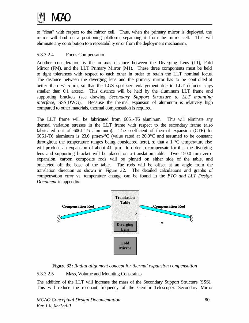
MCAO
MCAO Conceptual Design Documentation 80 Rev 1.0, 05/15/00
to "float" with respect to the mirror cell. Thus, when the primary mirror is deployed, the mirror will land on a positioning platform, separating it from the mirror cell. This will eliminate any contribution to a repeatability error from the deployment mechanism. 5.3.3.2.4 Focus Compensation
Another consideration is the on-axis distance between the Diverging Lens (L1), Fold Mirror (FM), and the LLT Primary Mirror (M1). These three components must be held to tight tolerances with respect to each other in order to retain the LLT nominal focus. The distance between the diverging lens and the primary mirror has to be controlled at better than +/- 5 µm, so that the LGS spot size enlargement due to LLT defocus stays smaller than 0.1 arcsec. This distance will be held by the aluminum LLT frame and supporting brackets (see drawing Secondary Support Structure to LLT mounting interface, SSS.DWG). Because the thermal expansion of aluminum is relatively high compared to other materials, thermal compensation is required. The LLT frame will be fabricated from 6061-T6 aluminum. This will eliminate any thermal variation stresses in the LLT frame with respect to the secondary frame (also fabricated out of 6061-T6 aluminum). The coefficient of thermal expansion (CTE) for 6061-T6 aluminum is 23.6 µm/m-°C (value rated at 20.0°C and assumed to be constant throughout the temperature ranges being considered here), so that a 1 °C temperature rise will produce an expansion of about 41 µm. In order to compensate for this, the diverging lens and supporting bracket will be placed on a translation table. Two 150.0 mm zero-expansion, carbon composite rods will be pinned on either side of the table, and bracketed off the base of the table. The rods will be offset at an angle from the translation direction as shown in Figure 32. The detailed calculations and graphs of compensation error vs. temperature change can be found in the BTO and LLT Design Document in appendix.
TranslationTable
x
y
DivergingLens
FoldMirror
Compensation RodCompensation Rod
Figure 32: Radial alignment concept for thermal expansion compensation
5.3.3.2.5 Mass, Volume and Mounting Constraints
The addition of the LLT will increase the mass of the Secondary Support Structure (SSS). This will reduce the resonant frequency of the Gemini Telescope's Secondary Mirror

MCAO
MCAO Conceptual Design Documentation 81 Rev 1.0, 05/15/00
Tip/Tilt System (M2TS) supporting structure. Therefore, it is a Gemini requirement that any additional mass being added to the top end must be limited to 125 ± 25 kg. This will include the LLT and all Beam Transfer Optics (BTO) components to be mounted on the SSS. A weight estimate table can be found in the BTO and LLT Design Document in appendix showing that our conceptual design meets the requirement. 5.3.4 Beam Transfer Optics
5.3.4.1 Laser path
A short description of the BTO layout is given in section 5.3.2. The conceptual design uses ultra-high reflectivity (R > 99%) dielectric mirrors and a few refractive optics with anti-reflection coatings at the laser wavelength to propagate the laser beams from the Laser System to the LLT. The total laser power and the outgoing beam quality requirements prevent the use of optical fibers for the BTO. Multimode fibers would stand the total laser power but degrade beam quality, whereas monomode fibers would suffer from low transmission due to coupling difficulties and Brillouin scattering. The power load on each mirror surface will be of the order of 300 W/cm2 corresponding to 5 overlapping CW, 10-W, 5-mm beams. The peak power load may be higher than that, especially if the laser is pulsed. A few mirrors will be fixed and used as simple fold mirrors, but others will be mounted on tip/tilt platforms controlled by the MCAO Control System. There are three different types of control loops in the BTO. (1) Along the laser path until mirror M6 mounted on the telescope top-end ring, control loops from one tip/tilt mirror to the other will correct for slow misalignment due to telescope flexures and thermal changes. A Position Sensing Device (PSD) mounted behind mirror Mn will measure the central beam position from light leaking through mirror Mn and notify the MCAO Control System to correct for misalignment by sending tip/tilt commands to mirror Mn+1. There will also be small cheap cameras looking at mirrors to visually pre-align the laser path before starting MCAO observations. (2) Mirrors M6 and M3 will be driven by the diagnostics measurements to control pointing and centering of the 5 laser beams at the LLT primary mirror. (3) M2 will be an array of 5 independent fast tip/tilt mirrors controlled independently by the MCAO Control System to correct for the fast turbulence-induced motion of the LGS’s on the sky. The sampling rate requirements are respectively 10 Hz for the slow tip/tilt loops and 800 Hz for the fast tip/tilt loops. The document Conceptual Design Review Material – Electronics, Sensors & Actuators in the Beam Transfer Optics describes in more details our baseline choices for BTO hardware (see appendix). When crossing above the primary mirror, the laser beams are parallel and stacked up in line in order to be hidden behind the 10-mm telescope vane. Each beam has a 99% encircled energy diameter smaller than 10 mm and the beams are separated by about 12 mm. The BTO includes a beam collimator made by lens L3 and L2 (see Figure 31) to re-collimate the naturally diverging gaussian beams along the telescope truss. It is a goal to make this afocal telescope assembly a zoom to optimize the beam diameters on the LLT primary mirror depending on seeing conditions. M3 also serves as an “X-constellation shaper” as described by Figure 33.
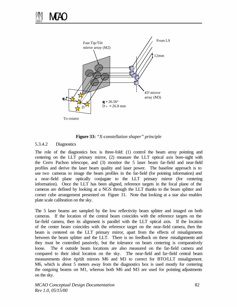
MCAO
MCAO Conceptual Design Documentation 82 Rev 1.0, 05/15/00
12mm
θθθθ = 26.56o
D < = 26.8 mm
Fast Tip/Tiltmirror array (M2)
45o mirrorarray (M3)
From LS
To rotator
D
Figure 33: “X-constellation shaper” principle
5.3.4.2 Diagnostics
The role of the diagnostics box is three-fold: (1) control the beam array pointing and centering on the LLT primary mirror, (2) measure the LLT optical axis bore-sight with the Cerro Pachon telescope, and (3) monitor the 5 laser beam far-field and near-field profiles and derive the laser beam quality and laser power. The baseline approach is to use two cameras to image the beam profiles in the far-field (for pointing information) and a near-field plane optically conjugate to the LLT primary mirror (for centering information). Once the LLT has been aligned, reference targets in the focal plane of the cameras are defined by looking at a NGS through the LLT thanks to the beam splitter and corner cube arrangement presented on Figure 31. Note that looking at a star also enables plate scale calibration on the sky. The 5 laser beams are sampled by the low reflectivity beam splitter and imaged on both cameras. If the location of the central beam coincides with the reference targets on the far-field camera, then its alignment is parallel with the LLT optical axis. If the location of the center beam coincides with the reference target on the near-field camera, then the beam is centered on the LLT primary mirror, apart from the effects of misalignments between the beam splitter and the LLT. There is no feedback on these misalignments and they must be controlled passively, but the tolerance on beam centering is comparatively loose. The 4 outside beam locations are also measured on the far-field camera and compared to their ideal location on the sky. The near-field and far-field central beam measurements drive tip/tilt mirrors M6 and M3 to correct for BTO/LLT misalignment. M6, which is about 5 meters away from the diagnostics box is used mostly for centering the outgoing beams on M1, whereas both M6 and M3 are used for pointing adjustments on the sky.

MCAO
MCAO Conceptual Design Documentation 83 Rev 1.0, 05/15/00
Depending on space envelopes, the diagnostics box could be located either between M3 and M2 or between M2 and the LLT. These locations are indicated as the “case I” and “case II” diagnostics box on the Beam Transfer Optics Conceptual Design For a Five-Beam array (LLT5PLAN.DWG) drawing appended to the MCAO CoDR document. Preference is given to the first location (case I) because the beams are not smeared yet by the fast tip/tilt motion induced by M2. 5.3.4.3 Other Components
5.3.4.3.1 Shutters
The BTO includes two shutters. The first shutter is located at the Laser System output. This is the fast shutter controlled by the safety systems via the MCAO Control System. It prevents the laser beams from propagating through the BTO (and subsequently the LLT and the sky) whenever needed, and particularly when an airplane is detected near the laser path to the sodium layer or in any other emergency situation. The safety shutter has a “power shutter” functionality as well and can dump the full laser power for any length of time. The so-called power shutter may be a slower system, located between the Laser System and the fast shutter. It will be water-cooled. The second shutter is located at the end of the BTO, near the LLT secondary assembly. Since cooling is not available behind the Secondary Support Structure (SSS), this shutter is made of two parts: one flip mirror mounted on the laser path between M2 and L1 to divert the beam onto the second part which is a water-cooled beam dump mounted on the top-end ring of the Gemini telescope. The dump will optionally be a power meter to enable absolute laser power measurements before the LLT. Since this shutter is only used for BTO system calibration purposes, there is no need to hide the beams behind a vane, and the beam dump can be conveniently located close to existing cooling and power supply installations. 5.3.4.3.2 Polarization control
The laser light is circularly polarized in order to maximize LGS brightness. However, the multiple reflections on the BTO mirrors will tend to depolarize the beams, so that their polarization would become elliptical before they are finally launched to the sky. To compensate for this depolarization effect, a polarization sensor samples the edge of the outgoing beams. The polarization sensor is mounted on top of the LLT structure (see the appended AutoCAD drawing: Beam Transfer Optics Conceptual Design for a Five Beam Array). The MCAO Control System uses the measurement result to drive a quarter-wave plate so that the beams remain circularly polarized after propagating through the BTO and LLT. 5.3.4.3.3 Rotator
At the end of the BTO there is a rotating K-prism whose purpose is to compensate for the LGS constellation rotation induced by telescope tracking. This rotator or “de-rotator” is located in front of the LLT secondary assembly, where the 5 beams almost overlap (see Beam Transfer Optics Conceptual Design for a Five Beam Array).

MCAO
MCAO Conceptual Design Documentation 84 Rev 1.0, 05/15/00
5.3.4.3.4 Tubes and covers
The laser path will be partly enclosed to answer three concerns: safety, scattering, and beam jitter due to turbulence. On the center section where laser beams are propagating at eye-level, the beams will be fully enclosed so that there is no laser-related risk for people walking nearby. Between mirrors M7 and M6 where the beams are propagating upward to the top-end ring, the laser path will not be fully enclosed but there will be demi-tubes instead, protecting the telescope field-of-view from non direct scattered light. According to calculations to date, scattered light is not an issue for the Gemini science path, but this extra precaution is taken for the same reason that the beams are to be hidden behind a vane when crossing over the primary mirror. Demi-tubes are used instead of full tubes so that air flow through the dome created by the Gemini vents prevents turbulence from building up in the tubes due to chimney effect. Note that this kind of turbulence is one of the major source of beam jitter and it must be controlled as much as possible. All BTO optical elements will have automated covers to protect them from dust whenever the laser is not propagated. This will significantly reduce optics cleaning maintenance and also prevents coating damage and beam quality distortions due to dust particles heating up on mirror surfaces. For the same reason, the LLT structure will have a fixed annulus cover on top of it. Individual mirror covers will be controlled by the MCAO Control System.
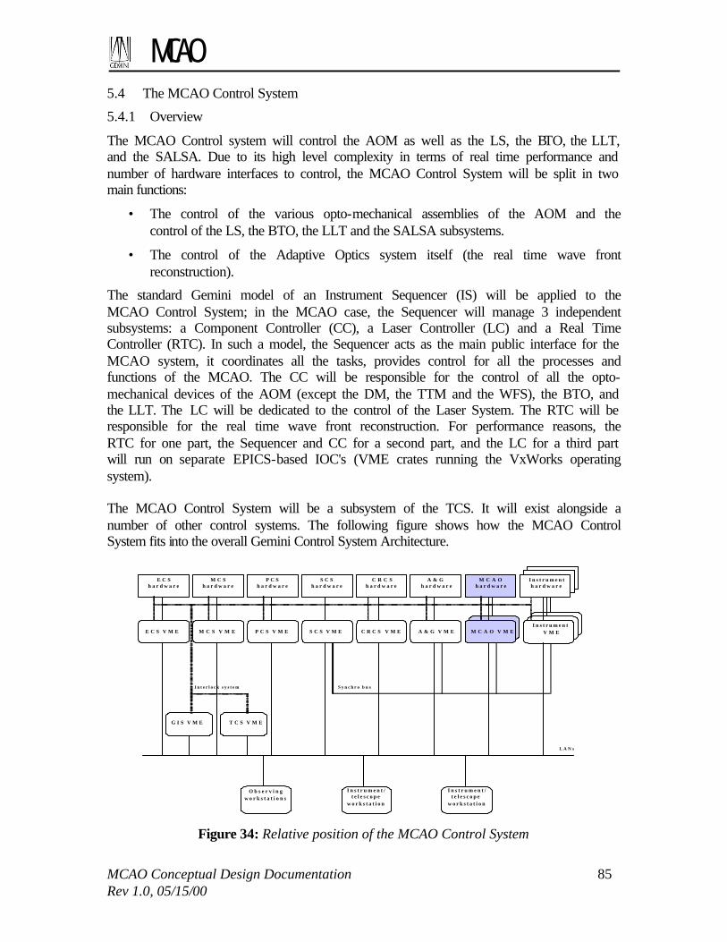
MCAO
MCAO Conceptual Design Documentation 85 Rev 1.0, 05/15/00
5.4 The MCAO Control System
5.4.1 Overview
The MCAO Control system will control the AOM as well as the LS, the BTO, the LLT, and the SALSA. Due to its high level complexity in terms of real time performance and number of hardware interfaces to control, the MCAO Control System will be split in two main functions:
• The control of the various opto-mechanical assemblies of the AOM and the control of the LS, the BTO, the LLT and the SALSA subsystems.
• The control of the Adaptive Optics system itself (the real time wave front reconstruction).
The standard Gemini model of an Instrument Sequencer (IS) will be applied to the MCAO Control System; in the MCAO case, the Sequencer will manage 3 independent subsystems: a Component Controller (CC), a Laser Controller (LC) and a Real Time Controller (RTC). In such a model, the Sequencer acts as the main public interface for the MCAO system, it coordinates all the tasks, provides control for all the processes and functions of the MCAO. The CC will be responsible for the control of all the opto-mechanical devices of the AOM (except the DM, the TTM and the WFS), the BTO, and the LLT. The LC will be dedicated to the control of the Laser System. The RTC will be responsible for the real time wave front reconstruction. For performance reasons, the RTC for one part, the Sequencer and CC for a second part, and the LC for a third part will run on separate EPICS-based IOC's (VME crates running the VxWorks operating system). The MCAO Control System will be a subsystem of the TCS. It will exist alongside a number of other control systems. The following figure shows how the MCAO Control System fits into the overall Gemini Control System Architecture.
C R C Sh a r d w a r e
M C A Oh a r d w a r e
S C Sh a r d w a r e
A & Gh a r d w a r e
P C Sh a r d w a r e
P C S V M E S C S V M E C R C S V M E A & G V M E M C A O V M E
I n s t r u m e n th a r d w a r e
I n s t r u m e n tV M E
T C S V M E
S y n c h r o b u s
M C Sh a r d w a r e
E C Sh a r d w a r e
E C S V M E M C S V M E
G I S V M E
L A N s
I n t e r l o c k s y s t e m
O b s e r v i n gw o r k s t a t i o n s
I n s t r u m e n t /t e l e s c o p e
w o r k s t a t i o n
I n s t r u m e n t /t e l e s c o p e
w o r k s t a t i o n
Figure 34: Relative position of the MCAO Control System

MCAO
MCAO Conceptual Design Documentation 86 Rev 1.0, 05/15/00
The MCAO Control System will interface the different subsystems of the MCAO System (AOM, BTO, LLT, LS and SALSA) with the Telescope Control System (TCS) and the Observatory Control System (OCS) as described in the following figure:
LLT hardware
Har
dwar
e si
deEPICS
ENGINEERINGGUIs
OCS GUI &SAD SCREENS
ALARMS SCREEN
ObservatoryControlSystem
StatusAlarm
Database
Telescope ControlSystem (EPICS)
MCAOControl System
(EPICS) – IS/CC
DataHandlingSystem
Archiver
EPI
CS
side
, Cha
nnel
Acc
ess
BTO hardwareSALSA
hardwareAOM
Laser SystemMCAO-RTC(EPICS)
Laser Hardware
Figure 35: Interface with the TCS/OCS
This solution has been chosen to be compliant with the MK AO system, Altair. However, an alternative would be to make the MCAO an “instrument” rather than a subsystem of the TCS. There will be some very complex sequences that need to be done at the level of the Sequencer, and perhaps it will be worth to do this sequencing out of EPICS and use a tool like ocswish. This alternative is being explored. 5.4.2 The MCAO Sequencer
The MCAO Control Sequencer (CS) will have 4 software components which are required to run on an EPICS based system. The Sequencer is the central and main process. It is responsible for receiving all the commands needed to control the MCAO. The commands will be sequenced and provided to the different sub-systems. All the commands from the Telescope Control System (TCS) will be sent through the Sequencer even if the command is dedicated to one of the sub-systems. The Sequencer will also synthesize all the action, status and health information of all the subsystems of the MCAO system, and will set accordingly a set of state records. The standard CAD commands required by the TCS will be implemented: reboot, init, park, test, debug as well as the standard status record (health, state, activeC, present, etc.), together with the apply record.

MCAO
MCAO Conceptual Design Documentation 87 Rev 1.0, 05/15/00
Dedicated sequences as well as simple commands (from the RTC and the MCAO CC) will be available through the sequencer:
- AO closed loop / open loop sequences, - AO calibration sequences, - LLT, BTO calibration sequence, - Emergency shutdown sequence.
The MCAO Sequencer will be capable of standalone operation during setup, maintenance and engineering time. It will be able to run completely disconnected from higher levels and/or other subsystems. The following figure describes the data flow between the different processes. The circles represent the processes itself, the simple arrows represent data transfer in the system and bold arrows represent continuous and high speed data.
Real time displays + fits
images to DHS
MCAO IS1
TCS commandsTCS command
status
TCS pointing
MCAO LC2
LC commands
LC status
SAD
MCAO CC3
MCAO RTC4
CC commands CC status
Interlock
SAD
RTC commands
RTC status
SAD
BTOFast TT
Observing data
M2 offload to SCS
M1 offload to TCS
BTO/LLT/SALSAAOM hardware
Laser hardware AOM WFS/DM
Devices control Devices
status
TTM/DM control WFS data
OIWFS data
Shared memory: CB,calibration data
Devices control
Devices status
Slow LGS WFS Focus
NGS WFS X,Y
position
Figure 36: Data flow diagram of the MCAO ICS
5.4.3 The Component Controller and the Laser Controller
These two components are responsible for controlling all of the opto-mechanical devices of the MCAO system (except the real time ones: the DM, TTM, and the NGS and LGS WFS). The Laser Component is not described in this document, because we do not know at this time what kind of laser we will use for the MCAO. The CC will interface only with the Sequencer for normal operations (commands and status). However for fast speed data communication, the synchro bus will be used, in

MCAO
MCAO Conceptual Design Documentation 88 Rev 1.0, 05/15/00
particular for the BTO fast tip-tilt commands between the MCAO RTC and MCAO CC processes. The CC will be implemented via custom EPICS Assembly and Device Control records to control all the motion devices. For some of devices such as fast TTM there will be some dedicated VxWorks tasks. The number of tasks and systems to control is significant and because some of the tasks will have to be very precise in terms of real time, we will need a multi-processor architecture, several Digital Input to Output control boards, DA boards, and AD boards. The standard Gemini boards (MVME2700 PowerPC board from Motorola for the CPUs, Bancomm board for the timing interface, and reflective memory board for communication with the synchro bus) will also be required. This component will have no interface with the DHS. The CC will have to control the following devices (all the records described below will have the prefix “mcao:cc:”) The M1 mirror of the LLT: The M1 mirror of the LLT is the only device remotely controlled by the CC component. It may be controlled through a single stepper motor driver, and a fine positioning control may also be needed (TBD). Also, two limit switches will be available to read the position of the M1 mirror. Several outputs and inputs of a standard Digital IO control board will be needed to perform the control. Description of commands and monitors are listed in the next table: Cad record Parameters Purpose LLTDeploy Deploy the M1 mirror of the LLT LLTPark Retract the M1 mirror of the LLT LLTLimGet Read the high and low limit switch values and
determined the position of M1: PARKED, DEPLOYED, MOVING, ERROR
Sir record Purpose LLTM1state State of the M1 of the LLT (PARKED, DEPLOYED,
MOVING, ERROR) The top end power shutter of the BTO: This shutter (a flip mirror) will be controlled through a single output of a Digital IO Module. Only one command will be available (see next table): Cad record Parameters Purpose topEndShutterCtrl - position
(BOOL, 0 or 1 for open/close)
According to the value of the position parameter, open or close the power shutter at the top end of the BTO

MCAO
MCAO Conceptual Design Documentation 89 Rev 1.0, 05/15/00
Sir record Purpose topEndShutterState State of the power shutter at the top end of the BTO
(OPEN, CLOSED, ERROR) M2 array of fast TTM of the BTO: These 5 fast TTM will be controlled at a rate of 800Hz. TT values will be provided by the RTC through the synchro bus, these values will be transformed into the TTM actuator space based upon the current orientation of the derotation mirror and applied to the TTM actuator at 800Hz rate. This is a critical process and we will need to have a dedicated CPU to handle this task. It will be a simple VxWorks task that will read the synchro bus, compute the actuator controls, apply some temporal filters as a PID and send the command to a Digital to Analog standard board (with 15 differential outputs). To Start and stop this control loop, we will use dedicated CAD commands (see next table): Cad record Parameters Purpose fastTTMove - Tip
- Tilt Move the fast TTM in tip and tilt values
fastTTLoopStart Start the fast TT closed loop fastTTLoopStop Stop the fast TT closed loop pidFastTTLoopSet For each of the
5 mirrors and for each actuators: P gain I gain D gain (doubles)
Set the PID parameters of the fast TT loop
Sir record Purpose fastTTLoopState State of the fast TT loop (OPEN, CLOSED, ERROR) The actuator controls can be monitored through a single gensub record. Also for diagnostic purposes, it will be possible to store the actuator controls in a dedicated circular buffer and to retrieve it when the closed loop is stopped. Positioning of beam relay optics L2 & L3 of the BTO: These beam relay optics will optionally be controlled in z position to optimize the width of the output laser beam for the current seeing. This will be done through 2 stepper motor drivers. The control of such drivers will be performed through a standard Digital IO control board. Description of commands and monitors are available in the next table: Cad record Parameters Purpose L2Move z (double) Move L2 relay in z direction L3Move z (double) Move L3 relay in z direction

MCAO
MCAO Conceptual Design Documentation 90 Rev 1.0, 05/15/00
relaysCalibrate For each relays, amplitude in z
Calibrate the relays versus the beam diagnostic sensor
relaysLoopStart -gain L2 (double) -gain L3 (double)
Start the relays closed loop
relaysLoopStop Stop the relays closed loop Sir record Purpose L3Z Position in Z of the L3 relay relaysLoopState State of the relays loop (OPEN, CLOSED, ERROR) Also during closed loop operations, the positions of the relays will be computed by a dedicated gensub record that will compute the positions from the beam diagnostic sensor at a slow rate (10s or more) to obtain a beam size matched to the current value of r0. Positioning of the rotator of the BTO: This rotator will have to be controlled. This will be done through a brushless DC servomotor which would require input/output from a standard Digital IO control board and also Digital to Analog output. Description of commands and monitors are available in the next table: Cad record Parameters Purpose rotatorMove angle (double) Move the rotator to the position requested Sir record Purpose rotator Position of the rotator The fast laser shutter at the entry of the BTO: This shutter will be controlled through a single output of a Digital IO Module. Only one command will be available (see next table): Cad record Parameters Purpose fastShutterCtrl - position
(BOOL, 0 or 1 for open/close)
According to the value of the position parameter, open or close the fast shutter of the BTO
Sir record Purpose fastShutterState State of the fast shutter at the entry of the BTO (OPEN,
CLOSED, ERROR) Control of the M3 slow TT mount and M6&M7 TTM of the BTO: The M3 mount, M6, and M7 will be controlled at a slow rate. TT values will be provided by the BTO beam and diagnostics sensors. This is a not critical process in terms of real

MCAO
MCAO Conceptual Design Documentation 91 Rev 1.0, 05/15/00
time performance. It will be controlled through dedicated gensub records at a very low rate. The different routines of the gensub records will be very similar: read the sensors, compute the actuator controls, apply some temporal filters as a PID and send the commands to a Digital to Analog standard board (requires 15 differential DA outputs). To Start and stop these control loops, we will use dedicated CAD commands (see next table): Cad record Parameters Purpose M3TTMove -tip (double)
-tilt (double) Move the M3 TT mount in tip and tilt values
M6TTMove -tip (double) -tilt (double)
Move the M6 TTM in tip and tilt values
M7TTMove -tip (double) -tilt (double)
Move the M7 TTM in tip and tilt values
TTCalibrate For each actuator of M3 mount, M6 and M7: Amplitude (double)
Calibrate M3 mount, M6 and M7 versus the sensors
TTLoopStart Start the slow M3 TT mount, M6 TT and M7 closed loop
TTLoopStop Stop the slow M3 TT mount, M6 TT and M7 TT closed loop
PidM3TTLoopSet For each actuators of the mount: P gain, I gain, D gain (doubles)
Set the PID parameters of the slow M3 TT mount loop
PidM6TTLoopSet For each actuators of the M6 TTM: P gain, I gain, D gain (doubles)
Set the PID parameters of the slow M6 TTM loop
PidM7TTLoopSet For each actuators of the M7 TTM: P gain, I gain, D gain (doubles)
Set the PID parameters of the slow M7 TT mount loop
Sir record Purpose TTLoopState State of the TT loop (OPEN, CLOSED, ERROR)

MCAO
MCAO Conceptual Design Documentation 92 Rev 1.0, 05/15/00
The actuator controls of M3, M6, and M7 will be monitored through a single gensub record. Also for diagnostic purposes, it will be possible to store the actuator controls of M3 mount, M6, and M7 into dedicated circular buffers and to retrieve them when the closed loops are stopped. The control of the quarter wave plate and the polarization meter: This quarter wave plate will be controlled through a single stepper motor driver. This will be achieved though IO of a standard Digital IO control board. Description of the commands and monitors are given in the next table: Cad record Parameters Purpose qwPlateMove Angle (double) Move the quarter wave plate to the requested
angle Sir record Purpose qwPlatePosition Position of the quarter wave plate During closed loop operations, the control of the quarter wave plate will be done through a lookup table according to the telescope position. Through an epics interface (a gensub record for example) running at a very slow rate (10s or more) the lookup table will be read and the quarter wave plate will be moved to the right angle. The control of the beam diagnostics: The BTO will have several sensors:
• 1 beam position sensor with quad cells and APD. This sensor will be read through Analog to Digital inputs and used to control the M7 TTM.
• 1 beam diagnostic sensor. The near and far field provided by this sensor will be used for diagnostic purposes, the beam divergence and diameter will be optionally used to control the L2 and L3 relays, the near-field beam position will used to control M6 and the beam tilt will be used to control M3 and M6. The sensor will include 2 cameras, and pixels values will be provided through a dedicated interface (TBD). From these pixel values it will be possible to compute the different information needed. One solution will be to used a COTS hardware and software system and to interface it to our VME crate.
The main commands are described in the following table: Cad record Parameters Purpose beamPosM7Acquire Acquire data from the beam position sensor used
to compute M7 and compute the centroids. beamDivAcquire Acquire divergence and diameter from the beam
diagnostic sensor beamPosM6Acquire Acquire near field beam position from the beam
diagnostic sensor

MCAO
MCAO Conceptual Design Documentation 93 Rev 1.0, 05/15/00
BeamTiltAcquire Acquire TT information from the beam diagnostic sensor
The values returned by the sensors will be monitored through gensub records. Positioning of NGS WFS’s of the AOM: The 3 NGS WFS of the AOM will have to be controlled in x and y position. This will be done through 6 stepper motor drivers. The control of such drivers will be performed through standard Digital IO control board Description of commands and monitors are available in the next tables: Cad record Parameters Purpose NGS1Move -x (double)
-y (double) Translate NGS WFS 1 in x and y direction of the amount indicated by the parameters x and y
NGS2Move -x (double) -y (double)
Translate NGS WFS 2 in x and y direction of the amount indicated by the parameters x and y
NGS3Move -x (double) -y (double)
Translate NGS WFS 3 in x and y direction of the amount indicated by the parameters x and y
Sir record Purpose NGS1X Position in X of the NGS WFS1 NGS1Y Position in Y of the NGS WFS1 NGS2X Position in X of the NGS WFS2 NGS2Y Position in Y of the NGS WFS2 NGS3X Position in X of the NGS WFS3 NGS3Y Position in Y of the NGS WFS3 The positions of the 3 WFS during AO closed loop operation will be provided through an EPICS interface to the CC by the RTC. The requested positions will be written in a gensub record (mcao:rtc:NGSWFSPos) by the RTC and used to update the NGS WFS positions in real time at a slow rate. The control of the sources of the AOM: The 3 NGS and 5 LGS simulated sources of the AOM will have to be controlled (on/off and in and out). The 5 LGS simulated sources of the AOM may also have to be adjustable in x and y position individually, and in z position jointly. There will also be 1 or 5 LGS reference sources within the AOM. These reference sources will have to be inserted, jointly adjustable in x and y position, and controlled (on/off). This will be done through up to 19 stepper motor drivers and some outputs and inputs of a standard Digital IO control board. Description of commands and monitors are available in the next tables: Cad record Parameters Purpose LGSSimSourceiMove i varies from 1 to 5
-x (double) -y (double)
Move the LGS simulated source i in x, y, position.
LGSSimSourceiPark Park the LGS simulated source i

MCAO
MCAO Conceptual Design Documentation 94 Rev 1.0, 05/15/00
LGSSimSourceiCtrl - value (BOOL, ON/OFF)
Control the LGS simulated source i (on/off)
LGSSimSourceZMove - z (double) Move all the LGS simulated sources in z direction
NGSSimSourcejIn j varies from 1 to 3
Move the NGS simulated source j in position
NGSSimSourcejPark Park the NGS simulated source j NGSSimSourcejCtrl - value
(BOOL, ON/OFF)
Control the NGS simulated source j (on/off)
LGSRefSourceiMove i varies from 1 to 5
-x (double) -y (double)
Move the LGS reference source i in x, y, position.
LGSRefSourceiPark Park the LGS reference source i LGSRefSourceiCtrl - value
(BOOL, ON/OFF)
Control the LGS reference source i (on/off)
Sir record Purpose LGSSimSourceiX Position in X of the LGS simulated source i (i varies from 1
to 5) LGSSimSourceiY Position in Y of the LGS simulated source i (i varies from 1
to 5) LGSSimSourceZ Position in Z of all the LGS simulated sources LGSSimSourceiState State of the LGS simulated source i (i varies from 1 to 5):
ON/OFF/ERROR NGSSimSourcejPosition Position of the NGS simulated source j (j varies from 1 to
3): IN/PARKED/ERROR NGSSimSourcejState State of the NGS simulated source j (j varies from 1 to 3):
ON/OFF/ERROR LGSRefSourceiX Position in X of the LGS reference source i (i varies from 1
to 5) LGSRefSourceiY Position in Y of the LGS reference source i (i varies from 1
to 5) LGSRefSourceiState State of the LGS reference source i (i varies from 1 to 5):
ON/OFF/ERROR The control of the science path ADC of the AOM: The science path ADC will be remotely controlled in position (in/out) and rotation for each of the two lenses. This will be done through stepper motor drivers, and several outputs and inputs of a standard Digital Input/Output control board will be used. Commands and states are described in the following tables: Cad record Parameters Purpose scienceAdcIn Move the science path ADC in position

MCAO
MCAO Conceptual Design Documentation 95 Rev 1.0, 05/15/00
scienceAdcPark Park the science path ADC scienceAdcRotate -angle lens 1
(double) -angle lens 2 (double)
Rotate the science path ADC
Sir record Purpose scienceAdcLens1 Angle of the lens 1 of the science path ADC scienceAdcLens2 Angle of the lens 2 of the science path ADC scienceAdcState Position of the science path ADC: IN/PARKED/ERROR The control of the NGS ADC of the AOM: The NGS ADC will be remotely controlled in rotation for each of the two lenses. This will be done through stepper motor drivers, and several outputs and inputs of a standard Digital Input/Output control board will be used. Commands and states are described in the following tables: Cad record Parameters Purpose NGSAdcRotate -angle lens 1
(double) angle lens 2 (double)
Rotate the NGS ADC
Sir record Purpose scienceAdcLens1 Angle of the lens 1 of the science path ADC scienceAdcLens2 Angle of the lens 2 of the science path ADC The control of NGS high order diagnostic sensor of the AOM: This camera will be mounted on an arm to allow X and Y position adjustment. This will be done through 2 stepper motor drivers and through a Digital Input Output control board. Commands and states are described hereafter: Cad record Parameters Purpose NGSHrwfsMove -x (double)
-y (double) Move in position x and y the high order wave front sensor of the NGS
NGSHrwfsPark Park the high order wave front sensor of the NGS Sir record Purpose NGSHrwfsX Position in X of the high order wave front sensor of the
NGS NGSHrwfsY Position in Y of the high order wave front sensor of the
NGS
MCAO
MCAO Conceptual Design Documentation 96 Rev 1.0, 05/15/00
The readout of the CCD and other diagnostics will be done through a AOA camera running on a sun workstation (same as our fama). The control of the LGS focus lenses of the AOM: Each lens of the LGS WFS will be remotely controlled in position (x, y and z) and in rotation (α and β). Some of these degrees of freedom may be removed. This will be done through 25 stepper motor drivers, and several outputs and inputs of a standard Digital Input/Output control board will be used. Commands and states are described in the following tables: Cad record Parameters Purpose LGSFocusiMove i varies from 1 to 5
-x (double) -y (double) -z (double) -α (double) -β (double)
Move the focus lens of the LGS WFS i in x, y and z, α and β
Sir record Purpose LGSFocusiX Position in X of the LGS WFS focus lens i (i varies from 1
to 5) LGSFocusiY Position in Y of the LGS WFS focus lens i (i varies from 1
to 5) LGSFocusiZ Position in Z of the LGS WFS focus lens i (i varies from 1
to 5) LGSFocusiAlpha Position in α of the LGS WFS focus lens i (i varies from 1
to 5) LGSFocusiBeta Position in β of the LGS WFS focus lens i (i varies from 1
to 5) Beam splitter wheel of the AOM: The Pcience Path beam splitter wheel will be remotely controlled in rotation. This will be done through 1 stepper motor driver, and several outputs and inputs of a standard Digital Input/Output control board will be used. Commands and states are described in the following tables: Cad record Parameters Purpose bsWheelRotate -θ (double) Rotate the beam splitter wheel of the angle θ Sir record Purpose bsWheelTheta Angle of the beam splitter wheel of the AOM Field stop for the NGS TT/WFS of the AOM: The field stops will be remotely controlled (OPEN/CLOSED) and may be adjustable (TBD). This will be done through 1 stepper motor driver. The control of such drivers will

MCAO
MCAO Conceptual Design Documentation 97 Rev 1.0, 05/15/00
be performed through standard Digital Input/Output control board. Commands and states are described in the following tables: Cad record Parameters Purpose fsOpen Open completely the NGS field stop fsClose Close the NGS field stop (to ~1 arc sec diameter) Sir record Purpose fsState State of the NGS field stop of the AOM
(OPEN/CLOSED/ERROR) Neutral density filter wheel for the NGS TT of the AOM: If automated, the neutral density filter wheel will be remotely controlled (4 positions). This will be done through 1 stepper motor driver. The control of such drivers will be performed through standard Digital Input/Output control board. Commands and states are described in the following tables: Cad record Parameters Purpose ndSelect - position
(integer 1 to 4) Select the neutral density
Sir record Purpose ndPosition Neutral density used (1 to 4) 5.4.4 The Real Time Controller
5.4.4.1 Main requirements
This computer will be dedicated to the Adaptive Optics control loop itself. It is the heart of the system and the most critical part in terms of real time performance. This system will handle 3 basic real time functions:
• The NGS real time control process, • The LGS real time control process, • The optimization and background processes,
As well as calibration and diagnostic functions (DM/WFS interaction matrix, WFS reference measurement, …). Due to the high level of real time operations, all these processes will be implemented on dedicated CPUs and will not be EPICS based. A separate CPU will run an EPICS interface to allow the MCAO Sequencer to control all these real time processes. The following epics commands (CAD) will be available:
• Acquire data from each LGS or NGS sensor, • Control each actuator of each TTM or DM, • Calibrate TTM versus the NGS wave front sensors, • Calibrate the DM's versus the LGS wave front sensors, • Measure the LGS or NGS WFS reference measurements, • Open and closed the NGS and/or LGS loops,

MCAO
MCAO Conceptual Design Documentation 98 Rev 1.0, 05/15/00
• Modify the gains of the temporal filters of the NGS and LGS loops, • Start and stop each of the background and optimization processes during closed
loop operations. The following figure gives a block diagram of what these processes are doing (NGS and LGS processes are indicated in bold). This is a more detailed version of Figure 3 in the OCDD appendix.
LGS WFS pixels (10)
NGS WFS pixels (0)
DMs actuator controls
Gain/Reference optimization(5)
TTM actuator controls
NGS DM actuator controls computation (4)
TTM temporal filter (3)
TTM actuator controls computation (2)
LGS DM actuator controls computation (12)
Control matrix selection (18)
DMs temporal filters (13)Σ
Telescope pointing
Gain/Reference optimization (17)
Extrapolate un-illuminatinedDM actuators
(14)
Offload M1via EPICS
records (20)
OIWFS measurements TTF
OIWFS measurementsblending (7)
Offload M2 via synchro bus (9)
+
+
Real Time display (15)
Adjust BTO TT, LGS WFS Focus MCAO CC (16)
NGS modal optimization (8)
Adjust NGS WFS position (6)
NGS WFS slopes
computation (1)
LGS WFS slopes
computation (11)
Null DMPiston,waffle,
Tilt (19)
Σ+
+
F
TT
Seeing
Figure 37 Real time processes block diagram
To communicate between these processes a database of shared memory objects will be defined. In particular, shared circular buffers will be defined to contain the WFS measurements and the actuator commands. All the parameters needed to close the loop and to optimize the real time processes will be available through this database of shared memory objects. Also because of the high speed requirements and the high rate of data to transfer, the RTC will have to communicate directly with the DHS through the LAN, and with the SCS, OIWFS and MCAO CC via the synchro-bus and through the EPICS database with the TCS.

MCAO
MCAO Conceptual Design Documentation 99 Rev 1.0, 05/15/00
The NGS and LGS processes will have to be synchronized. The LGS WFS will drive the loop timing for both the NGS and the LGS. In fact, the LGS WFS will wake up the LGS process as soon as a packet of pixels is read. The LGS process will start the centroid computation and the matrix multiplication and wait for the next packet. To reduce the latency between the NGS measurement and the DM commands, the LGS WFS process will wake up the NGS process after a certain amount of time as shown in the following figure:
LGS WFS exposure time1.25ms
LGS WFS readout time(10) – 1ms
LGS DM computation
(11), (12)
NGS TTM computation(1), (2), (3) - 0.05µs
NGS DM computation(4)- 20 µs
NGS WFS exposure time1.25ms
NGS WFS readout time(0)
Final DM computation(13), (14),
(15)
TTM commands
DMcommands
TTM commands
DMcommands
DMcommands
TTM commands
DM1DM2DM3
DM1: 17 µsDM2: 20 µsDM3: 9 µs
Figure 38: Synchronization of the real time processes
5.4.4.2 NGS Requirements and Algorithm Description
The NGS process corresponds to the blocks (0), (1), (2), (3) and (4) in Figure 37. The NGS control system is composed of:
• 3 WFS each a 2x2 Shack-Hartmann (APD type to have a zero electron read noise and a minimal read time)
• a Tip Tilt Mirror (TTM) The NGS real time process or control loop can be synthesized into these main sub tasks executed sequentially at a rate of up to 800 Hz:
• To read the 3 WFS (0). The NGS process is woken up by the LGS process and starts to read the APD signals.
• From these APD signals, the NGS process computes the tip/tilt information (6 inputs) for all the WFS, subtracts references and stores these tip/tilt measurements into a circular buffer (1). Then the tip/tilt measurements are used as input signals

MCAO
MCAO Conceptual Design Documentation 100 Rev 1.0, 05/15/00
to compute the actuators control of the TTM (2 outputs). It corresponds to a simple matrix multiplication (2) using a preloaded control matrix in memory.
• A temporal filter is applied to the TTM command vector (3); it can be a simple integrator with a proportional gain or something more elaborate. These TTM actuator controls are also stored into a dedicated circular buffer.
• Finally, the tip/tilt measurements are also used as inputs to compute the tip/tilt anisoplanatism modes of the DM’s (4). This is done also through a simple matrix multiplication (matrix preloaded in memory) and the output commands are fed into the LGS control loop. This matrix multiplication consumes a lot of time in comparison to task (2) and is done after sending the actuator controls to the TTM.
The matrices are computed by the calibration processes before closing the loop and are optimized by the modal optimization process (8) when the loop is closed. Gains for all the NGS modes or anisoplanatism modes are included into the control matrices. At a slow rate, once per second, the reference measurement vector will be updated by the background process “OIWFS measurements blending” (7), and at a slower rate by the optimization process “Reference optimization (5)”. This process is not a critical process at least in comparison with the LGS process. The total number of operations for all these tasks is around 9 Mflops or 4.5 Mega mult/add/s, and can be achieved with a simple Power PC CPU 750 running at 366Mhz for example. 5.4.4.3 LGS Requirements and Algorithm Description
This LGS process is the most critical one in terms of real time performance. It corresponds to the blocks (10), (11), (12), (13) and (14) in Figure 37. The LGS process is composed of:
• 5 Shack Hartmann WFS, each composed of 16x16 sub-apertures, with each sub-aperture composed of 2x2 pixels and a guard row and column of pixels between each sub-aperture. The number of illuminated sub-apertures per WFS will be only 204. Either a single EEV CCD50 with 16 outputs and with 128x128 pixels will be used, or 5 EEV CCD39’s with 4 outputs and 80x80 pixels each.
• 3 DM’s with different geometries: Deformable mirror Number of actuators Number of active
actuators Number of actuators to extrapolate
DM1 21x21 17x17 – 48 = 241 349 – 241 = 108 DM2 24x24 20x20 – 48 = 352 468 – 352 = 116 DM3 17x17 13x13 – 24 = 145 241 – 145 = 96 The LGS real time process or control loop can be synthesized into these main sub tasks at a rate of up to 800 Hz. In contrast to the NGS, these tasks will be parallelized as much as possible:
• Read the 5 WFS (10). The LGS WFS electronics clocks the LGS control loop, and the process starts to read the WFS pixels. The pixels are flat-fielded and bias- subtracted before the slope computation.
MCAO
MCAO Conceptual Design Documentation 101 Rev 1.0, 05/15/00
• From these pixels, the LGS process computes the slope information (2040 inputs) for all the WFS following a standard centroid algorithm, subtracts references and stores these slope measurements into a circular buffer (11). Then the slope measurements are used as input signals to compute the commands for active DM actuators (738outputs). It corresponds to a single matrix multiplication (12) using a preloaded matrix in memory. The 738 error signals are then co added to the NGS output vector (4).
• At a slow rate, a control vector given by the background process “Null DM piston, waffle, tilt and tilt anisoplanatism modes” (19) will be also co added to the real time outputs.
• A temporal filter is applied to the DM actuator command vector (13); it can be a simple integrator with a proportional gain or a more general second order filter. These DM actuator commands are also stored into a circular buffer.
• From the integrated outputs the commands for the unilluminated actuators are extrapolated (14), using a simple algorithm such as nearest neighbor slaving.
As for the NGS closed loop process, the matrix is computed by the calibration processes before closing the loop and is updated by a background process while the loop is closed according to the telescope position. Gains for all the LGS actuators are included into the LGS control matrix. At a slow rate, once per second, the reference measurement vector will be updated by the background process “OIWFS measurements blending” (7), and at a slower rate by the optimization process “Reference optimization (17)”. This process is the most critical in terms of real time performances. The number of operations (an addition plus a multiplication) required is around 1.5 Giga mult/add/s and corresponds to 3 GFlops. The most demanding task is the matrix multiplication (12). However such a requirement is not impossible, and today several solutions are available based on parallel and multi processor architectures such DSP or PPC multi processor boards (see Section 5.4.4.7). 5.4.4.4 Optimization and Background Processes
The optimization and background process corresponds to the blocks (5) to (9) and (15) to (20) in Figure 37. The goal of such processes is to continuously optimize or update the different parameters of the closed loop processes and also provide data to outside components such as the MCAO CC or the DHS. Therefore they are closed loop processes, but run at a slow rate in comparison to the LGS and NGS processes. They will be grouped and implemented on different CPUs (see Section 5.4.4.7). NGS modal optimization process (8): The goal of this process is to optimize the modal closed loop gains according to the atmospheric turbulence.

MCAO
MCAO Conceptual Design Documentation 102 Rev 1.0, 05/15/00
To perform such an optimization, it is necessary to have the real time values for the TTM modes and for the DM anisoplanatism modes. The choice of the modal basis may change from field to field but will be fixed for each science observation. The real time modal values are obtained from a simple matrix multiplication (5,6) with the 6 slope inputs from the NGS process. This simple computation (30 add/multiply pair) will be performed by the NGS process, and the mode values will be stored into a dedicated circular buffer. This mode circular buffer will be big enough to allow the optimization process to read at least 1024 mode records while the NGS process continues writing new values. For each of these 5 modes, the square modulus of the FFT is computed using the inputs of the 1024 mode records, and then divided by the square modulus of the loop transfer function for each corresponding mode. This is repeated a few times and the resulting functions for each mode are averaged and the optimized modal gains are determined. The control matrices used during the steps (2) and (4) are recomputed and stored into the memory of the processor dedicated to the NGS process without disturbing the NGS process. The control matrix buffers will be doubled and the new control matrixes will be downloaded in the non-used part of the buffer. A semaphore will be set to warn that at the next iteration of the NGS closed loop new control matrices will be available. This process is time consuming. A goal is to update the gains at a rate of 10s. Gain and reference Optimization process (5) and (17): The goal of this process is to optimize the slope reference vectors and gains of the different WFS according to the atmospheric turbulence, using algorithms as developed for Altair. Adjust NGS WFS position process (6): This process reads the NGS tip-tilt measurements from the dedicated circular buffer, averages them and computes the corresponding NGS WFS X and Y positions to null the average tip-tilt measurements to stay in the dynamic range of the NGS WFS. These X and Y data are time stamped and written into dedicated SIR records (6 positions). The MCAO CC will read these SIR records and will accordingly move the three NGS WFS. OIWFS measurements blending process (7): The TTF errors provided by the OIWFS at a rate of up 200 Hz are read from the synchro-bus, averaged and transformed into the NGS and LGS WFS reference measurement vector by a simple matrix multiplication. The reference vector given by the OIWFS TT values are used to update the NGS WFS reference vector (a simple addition to the previous NGS reference vector), and the reference vector given by the focus value is used to update the LGS WFS reference vector (again a simple addition to the LGS previous reference vector). This adjustment is done at low gain, is not time consuming, and is not critical in term of synchronization with the closed loop process.

MCAO
MCAO Conceptual Design Documentation 103 Rev 1.0, 05/15/00
Adjust the TTF of the MCAO CC (16): The purpose of this process is to compute the focus value to apply to the focus lens of LGS WFS and to compute the TT values to send to the fast TTM of the BTO. It consists of the steps:
• First, this process is synchronized with the LGS process via a simple semaphore. • Next, it reads the LGS slopes from the dedicated circular buffer and computes the
TTF values for each LGS WFS (5 x 2 + 5 data) by a simple matrix multiplication. • The TT data are then time stamped and written into the synchro bus, and will be
available for the MCAO CC. This will read the synchro bus and update the 5 BTO TTM.
• The Focus data will be averaged together for several frames to obtain a single long-term average focus value to be sent to the MCAO CC through an EPICS SIR record. This focus value will be used to update the position of the LGS WFS lens.
This process is not time consuming, but needs to be able to send fast TT values to the BTO at a rate of up to 800 Hz and to be synchronized with the real time processes. This is not an issue, but adds another constraint to the whole system. Offload M2 and M1 process (9) and (20): These tasks are is in fact a single process:
• First, this process is synchronized with the NGS/LGS processes via a simple semaphore.
• The process reads the TTM commands from the shared circular buffer and computes the corresponding M2 TT modes via a (2,2) matrix multiplication.
• The process reads the DM commands from the shared circular buffer and computes the corresponding M1 modes including the focus mode via a (19,738) matrix multiplication.
• These steps are repeated, in order to filter the TT modes and average the DM modes.
• The filtered TTF values are then formatted into SCS/M2 coordinates, time stamped and sent to the SCS/M2 via the synchro bus (9).
• The other modes are scaled and formatted into M1 coordinates, time stamped and written into the shared memory of the RTC. These data are then available to the TCS through a gensub record of the MCAO RTC EPICS database (19).
This process is not critical in terms of number of operations to perform (14000 operations at each iteration). It needs to be synchronized with the real time processes so that the TTM commands are optimally offloaded to M2. The LGS control matrix selection process (18): The MCAO Sequencer reads the telescope elevation from the TCS records at a rate of once per second, and transfers through EPICS this information to the RTC EPICS interface process. This one writes these information into the shared memory for the RTC and sets a semaphore to wake up the corresponding background process. The purpose of

MCAO
MCAO Conceptual Design Documentation 104 Rev 1.0, 05/15/00
the background process is to download to the LGS process a new control matrix from a lookup table based upon the telescope elevation. As explained in the previous chapter, the LGS matrix multiplication will certainly be shared between several processors. Each processor will take care of a part of the matrix multiplication and for this purpose will have the corresponding part of the control matrix in its own memory. This internal processor buffer will be doubled and the control matrix portion will be downloaded in the non-used part of the double buffer to not delay the LGS real time process. A semaphore will be set to signal at the next iteration of the LGS closed loop that a new control matrix is available. Null the piston, waffle, tilt and tilt anisoplanatism modes of the DM (19): The aim of this process is to check is there is no drift for the piston, waffle, tilt and tilt anisoplanatism modes of the DM figure even if they are not controlled (filtered from the control matrix). It consists of:
• The process reads the DM commands from the shared circular buffer and computes the piston, waffle, tilt, and tilt anisoplanatism mode values of the vector of actuator commands.
• The operation is repeated in order to obtain a long term average of these modes, and the averaged values are transformed back to actuator commands in order to be subtracted from the DM actuator control at the next real time LGS closed loop iteration.
This process is not time consuming. It need not be synchronized with the LGS real time process. Real time display (15): The LGS and NGS slope measurements, as well as the actuator commands, will be read from the different circular buffers at a slow rate, formatted and sent to the DHS Quick Look Tool (QLT) for diagnostic purposes. WFS pixel information will be read from the circular buffers and sent to the DHS for permanent or temporary storage, or for display with the QLT. Some optimization parameters, as the mode values (TTM and DM anisoplanatism modes) will be also read from the dedicated circular buffer, formatted and sent to the DHS QLT for debugging purposes. This is similar to the Altair system, and the goal will be to reuse part of the code already implemented. 5.4.4.5 Calibration Processes
The calibration processes will consist of daytime measurements of the following parameters:

MCAO
MCAO Conceptual Design Documentation 105 Rev 1.0, 05/15/00
• The interaction matrices between the DM and the LGS WFS using the LGS simulated source, and between the TTM and the NGS WFS using the NGS simulated source,
• The DM and TTM offset voltages used by the temporal filters, • LGS WFS reference slope measurements.
The data are loaded into the dedicated processors used by the different tasks prior to running in closed loop mode. 5.4.4.6 Diagnostics
All real time information will be stored into circular buffers (CB). These CBs will be shared between the 3 processes. They will contain:
• WFS images (pixels), • WFS slope measurements (tip/tilt and centroids), • TTM and DM actuator commands, • TTM and DM anisoplanatism mode commands,
Data will be simple floating point values. Examples of what can be stored in each CB: • 100 records for the image CB, • 4096 records for the slopes CB, • 4096 records for the deformable actuator controls CB, • 8192 records for the mode CB.
This will lead to 52 Mb. The circular buffer implementation will be architecture dependant. In the case of the baseline approach described in the next paragraph, for example, the actuator control circular buffer will be split and implemented on 3 different boards. 5.4.4.7 Hardware Options and Baseline Approach
LGS control is the major user of CPU power with the matrix multiplication being the most critical part. Performance at the level of 3 Gflops is required. Fortunately such performance is now available from several manufactures, with boards based on DSP or PowerPC processors delivering 4 to 16 Gflops. Based on our experience with Altair, we have studied in more detail a solution based on PowerPC processors. We also are confident that a DSP solution will be very well adapted to our system. The next step of our work will be to benchmark these different solutions and to choose one. 5.4.4.7.1 PowerPC solution
The solution we propose here is based on Synergy G4 PowerPC (PPC) processor. This powerful board (VSS4) contains 4 G4 PowerPC (AltiVec) running at 466MHz and has many nice features including 2 Mb of L2 cache, a PCI bus, a PMC site and the PEX3 option that provides 3 additional PMC sites, as well as a dedicated hand coded math library. Such a solution will give us a lot of flexibility, will be easier to program and to develop compared to the DSP solutions described above, and will be very compact.
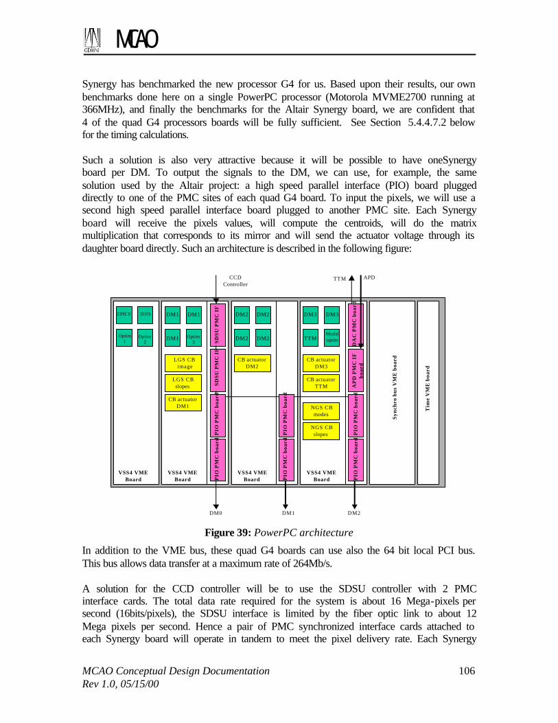
MCAO
MCAO Conceptual Design Documentation 106 Rev 1.0, 05/15/00
Synergy has benchmarked the new processor G4 for us. Based upon their results, our own benchmarks done here on a single PowerPC processor (Motorola MVME2700 running at 366MHz), and finally the benchmarks for the Altair Synergy board, we are confident that 4 of the quad G4 processors boards will be fully sufficient. See Section 5.4.4.7.2 below for the timing calculations. Such a solution is also very attractive because it will be possible to have oneSynergy board per DM. To output the signals to the DM, we can use, for example, the same solution used by the Altair project: a high speed parallel interface (PIO) board plugged directly to one of the PMC sites of each quad G4 board. To input the pixels, we will use a second high speed parallel interface board plugged to another PMC site. Each Synergy board will receive the pixels values, will compute the centroids, will do the matrix multiplication that corresponds to its mirror and will send the actuator voltage through its daughter board directly. Such an architecture is described in the following figure:
Syn
chro
bu
s V
ME
boa
rd
Tim
e V
ME
boa
rd
DM2
TTM
DM3DM3
TTM
VSS4 VME Board
DM1DM0
DM2 DM2
DM2DM2DM1 DM1
DM1
EPICS DHS
Modaloptim
CCD Controller
LGS CB image
LGS CB slopes
CB actuator DM1
CB actuator DM2
CB actuator DM3
CB actuator TTM
NGS CB modes
NGS CB slopes
Optim1
Optim2
Optim3
SD
SU
PM
C I
FS
DS
U P
MC
IF
PIO
PM
C b
oa
rdP
IO P
MC
bo
ard
VSS4 VME Board
VSS4 VME Board
VSS4 VME Board
DA
C P
MC
bo
ard
AP
D P
MC
IF
b
oard
PIO
PM
C b
oa
rdP
IO P
MC
bo
ard
PIO
PM
C b
oa
rdP
IO P
MC
bo
ard
APD
Figure 39: PowerPC architecture
In addition to the VME bus, these quad G4 boards can use also the 64 bit local PCI bus. This bus allows data transfer at a maximum rate of 264Mb/s. A solution for the CCD controller will be to use the SDSU controller with 2 PMC interface cards. The total data rate required for the system is about 16 Mega-pixels per second (16bits/pixels), the SDSU interface is limited by the fiber optic link to about 12 Mega pixels per second. Hence a pair of PMC synchronized interface cards attached to each Synergy board will operate in tandem to meet the pixel delivery rate. Each Synergy

MCAO
MCAO Conceptual Design Documentation 107 Rev 1.0, 05/15/00
board will have a second PIO board dedicated to input the CCD data. These 3 PIO boards will be wired in parallel and will see the same data simultaneously. A specific PMC interface board will be used to input the NGS data, and a Digital to Analog PMC board will be used to output actuator controls to the TTM,. These boards will be plugged on the last Synergy board. The optimization processes and backgrounds processes will communicate through the PCI bus to allow fast transfer of data, and will free the VME bus if it is required to transfer data. These new boards require us to have a VME64 back plane. This back plane is fully compliant with a VME standard 32. It will be possible to use our standard Gemini board for the synchro bus and the timing interface. 5.4.4.7.2 Timing estimates
The following estimates are based upon benchmarks and our expertise on PowerPC processors: DM0 Time for one single G4 processor
Centroids computation 0.154ms Reference subtraction 0.030ms Matrix computation 2.212ms Filter and add commands 0.007 ms Guard actuator computation 0.005ms DM0 total 2.408ms (requires 3 processors)
DM1
Centroids computation 0.154ms Reference subtraction 0.030ms Matrix computation 3.23ms Filter and add commands 0.010ms Guard actuator computation 0.005ms DM1 total 3.429ms (requires 4 processors)
DM2
Centroids computation 0.154ms Reference subtraction 0.030ms Matrix computation 1.33ms Filter and add commands 0.004ms Guard actuator computation 0.004ms DM2 total 1.522ms (requires 2 processors)
As described in the previous figure, we will use 3 processors on the second board to compute the outputs of the DM0, all the processors of the 3rd board to compute the

MCAO
MCAO Conceptual Design Documentation 108 Rev 1.0, 05/15/00
outputs of the DM1, and 2 processors of the last quad G4 board for DM2. The first quad G4 board will be shared between the EPICS tasks, the DHS, and some optimization and background processes. The 2 processors of the last quad G4 board that are not used for the control of DM3 will be used to compute the output for the TTM and to optimize the NGS modal control algorithm . The next step now will be to get such a board and do the definitive benchmarks we need. 5.4.4.7.3 Alternative Real-Time-Control Solutions
Two DSP solutions were considered:
• The SOR approach: This system has been built to support the real time wave front reconstruction for a 941-actuator DM at a sampling frequency of 2.5 KHz. This system uses 1024 16-bit integer DSP processors operating at 20MHz. The architecture is based up 1 processing element per actuator, and has a computing power of 10 Gflops. The DSP processors are grouped 8 per VME board. This leads to 128 DSP boards. This is a proven solution and can be copied and adapted for the MCAO system, which has a reduced sampling frequency. The SOR people are also working on a new generation of wave front reconstructors based on both DSP and FPGA (Field Programmable Gate Arrays) processors. This new generation will be more flexible and hopefully more compact.
• The SHAKTI/ONERA solution: A customized DSP system is being developed for the VLT Adaptive Optics system NAOS, and like the SOR type is dedicated to adaptive optics systems. The SHAKTI real time computer is based on a modular architecture, using mother VME boards on which it is possible to plug up to 4 modules (acquisition/equalization module, graphic display module, DSP computation module, Digital to Analog module). The important part is the computation module, which actually contains 3 32-bit DSP processors TMS320C40. This solution can drive a 195-actuator DM at a sampling frequency of 500 Hz and can handle up to 150 Mflops per computation module. This solution is actually not powerful enough to fit our requirements, but it could be upgraded with TMS320C67 processors allowing around 1 Gflop computing power per computation module. It is possible to have several computation modules. This new generation will be not only more powerful, but also very compact and flexible and should fit our requirements.
Other DSP solutions must also be studied, such the PENTEK, SPECTRUM with 4 TMS320C67 DSP processors on VME boards with a PMC interface, and SHARC processor boards. 5.4.4.7.4 DM and WFS interfaces
Three of the four processor boards will be independently responsible for the reconstruction and control of one DM each. The interface solution used for Altair project meets the requirements here. The General Standards Corporation’s PMC-HPDI32 card is custom programmed to directly interface to the Xinectics DM electronics. Data transfers

MCAO
MCAO Conceptual Design Documentation 109 Rev 1.0, 05/15/00
by the processor fill a FIFO on the PMC interface card which simultaneously drives the parallel interface to the DM electronics. Xinetics specifies a 10 MHz (16-bit) limit. This leads to a 100 ns / actuator transfer time (plus setup time). Therefore, the transfer time for the largest DM (468 actuators for DM2) will be about 50 microseconds. The parallel interface port on the SDSU interface card will be utilized to simultaneously broadcast the data from the LGS WFS controller to the three processor boards. The 3 CPU boards will each have a 32bit PMC parallel interface card with DMA capability. Each SDSU interface card will provide a 16-bit pixel to half of the parallel input cards at each data transfer strobe. There will be 8 million 32-bit pixel-pairs per second delivered over this parallel “bus.” This is well within the 25 million 32-bit/s capability (100 Mb/s) of, for instance, the General Standards Corporation’s PMC-HPDI32. 5.4.5 VME Hardware Requirements
The control and interface electronics for the system are based on commercially available VME cards and racks. The AOM electronics will be mounted within the AOM on the ISS and the remainder, primarily associated with the BTO, will be mounted on the center-section. All will be contained in standard ISS-mounted thermal enclosures, as per Gemini Interface Control Document ICD 1.9/3.7 (Science Instruments to Facility Thermal Electronics Enclosures). The VME cards fall into the following categories.
• Digital I/O – TTL or higher-power input-output, used for control signals, driving solenoid-type mechanisms, reading limit-switches etc. Examples are the Xircom XVME-240 and XVME-244, 6U cards.
• Analogue I/O – ADC and DAC cards for generating analog demand signals and reading sensor information (for example, in the BTO beam steering loops). Examples are the Xircom XVME-531 (12-bit DAC) and XVME-566 (12-bit ADC), 6U cards.
• High-performance processors – PowerPC processors to implement the NGS and LGS real-time controller functions.
• Deformable mirror drivers – a Xinetics product, as used in the Gemini instrument Altair, capable of controlling 32 DM channels per 9U card.
• Support cards – those required for general processing, housekeeping tasks and other support activities; for example Bancomm time cards, reflective memory and general CPUs (Motorola MVME-2700 PowerPC).
These cards will be housed in standard 21-slot 6U and 9U racks within the thermal enclosures. Suitable racks are available from numerous sources, an example being APW Electronic Solutions “Smart Chassis” range. A minimum of 5 21-slot VME racks will be required, 2 6U and 3 9U. The 3 9U racks will hold the deformable mirror driver electronics and will be ISS-mounted; one 6U rack will also be ISS-mounted and a supplementary rack in the center-section cabinet will house the BTO electronics.

MCAO
MCAO Conceptual Design Documentation 110 Rev 1.0, 05/15/00
The following tables summarize the card requirement and the crate requirement.
Designation Function No. of cards Card size (U) XVME-240 TTL-level digital I/O 4 6 XVME-244 Optoisolated high-power digital I/O 1 6
XVME-212 Optoisolated digital I/O (w. interrupt generation)
1 6
XVME-531 12-bit analogue output module (DAC) 2 6 XVME-566 12-bit analogue input module (ADC) 1 6
Xinetics Deformable Mirror driver
32-channel DM driver cards 34 9
MVME2700 MCAO CC processor board 2 6 Synergy G4 PowerPC RTC processor board 4 6
Bc635VME Bancomm board 2 6 VMIVME5588 Reflective memory board 2 6 PMC-HPDI32 High speed parallel I/O PMC board 6 ?
SDSU interface board SDSUII PMC board 2 ? PMC-DAC PMC DAC board 1 ?
PMC APD interface board 1 ?
Total: 63 excl. misc. support cards
Designation Description Quantity Location
TBD VME rack, 9U, 21-slot with integral power supply
3 ISS
TBD VME64 rack, 6U, 21-slot with integral power supply
1 ISS
TBD VME rack, 6U, 21-slot with integral power supply
1 Center-section
5.4.6 Power Requirements
These are difficult to estimate with any degree of accuracy as power consumption data is not readily available for all the proposed cards. However an approximation may be made by assuming a ‘typical’ VME card to have the following consumption figures:
• 3.0A at +5VDC, power consumption 15W, • 0.5A at +12VDC, power consumption 6W, • 0.5A at –12VDC, power consumption 6W.
This gives a total per-board estimate of 27W. Assuming the 63 cards as listed above plus an additional 7 miscellaneous gives a total of 70 cards. The estimate of total power consumption by the VME cards is therefore approximately 70 × 27W = 1890W. This load will of course be divided amongst the three (or more) VME crates. Assuming equal load in each, the nominal per-crate loading is 500-600W, which is acceptably handled by standard power supply configurations. 5.5 Safe Aircraft Localization and Satellite Acquisition system (SALSA)
The propagating laser beams will cross airspace used by commercial and private aircraft, and propagate to altitudes of low- and high- earth-orbiting satellites. In the U.S. research groups propagating lasers into the sky must notify the Federal Aviation Administration

MCAO
MCAO Conceptual Design Documentation 111 Rev 1.0, 05/15/00
and Space Command prior to propagating the laser. With the FAA past groups including Lawrence Livermore National Labs and the University of Chicago have received certificates of non-objection. The FAA has not objected to rerouting commercial aircraft around lasers at remote sites, and the only operational hurdle is the FAA acceptance of automated rather than human spotters. There is an FAA working group drafting guidelines concerning all outdoor propagation of lasers including research use and light shows. The group is also exploring ways to receive radar feeds from the FAA to monitor airspace above sites. This could remove the need for a human spotter. The Civil Aviation Agency in Chile will be approached with a summary of the above guidelines as well as a summary of the proposals sent to the FAA by US, UK, and European groups. With Space Command things will be more difficult. All communications are via fax, perhaps to hinder the acquisition of a satellite database and the passing of computer viruses. In the case of low-power lasers (e.g., CW of less than 3 Watts) at least one organization has received a waiver of Space Command notification (University of Arizona). A solution will need to be found for queue scheduling of the MCAO and other LGS AO systems. A number of aircraft avoidance systems will be in place on the summit at Cerro Pachon to monitor air traffic above the site. These include systems to prevent beam crossings by airplanes and satellites, and systems such as the observatory's all-sky cloud monitor to monitor for clouds that could interfere with the laser propagation and return. Aircraft detection will be accomplished with all-sky visible cameras and with a redundant telescope bore-sighted IR camera. The all-sky cameras will be used as an early warning system with generally several minutes between detection and beam crossings. They serve as plane spotters. The bore-sight IR camera are used as a backup system with a typical detection-to-beam-crossing times of a few seconds. Additionally, we will inquire with the CAA about having local radar feeds communicated to the summit to monitor air traffic. Monitoring crossings by wildlife (e.g. Andean condors) is TBD. If system receives a “HALT” command, the system, if time permits, will attempt to stop gracefully. The focal-plane instrumentation will be shuttered/stopped, the AO correction is halted, the laser is shuttered, and an alarm is sounded to inform the telescope operator.

MCAO
MCAO Conceptual Design Documentation 112 Rev 1.0, 05/15/00

MCAO
MCAO Conceptual Design Documentation 113 Rev 1.0, 05/15/00
6 COMMISSIONING, CALIBRATION, AND CONCEPT OF
OPERATIONS This section summarizes the calibration and commissioning tasks and highlights the operation and overheads as viewed by the astronomer. For further information, please refer to the OCDD and FPRD in the appendix. 6.1 Commissioning tasks
During instrument commissioning, several “on-telescope” or “on-sky” calibrations are required for the instrument, and its science operations must be verified. During system integration, each of the subsystems and the system as a whole will be tested in the lab prior to being put on the telescope. However, some calibration tasks will be done (or redone) on the telescope. Examples of these include measuring DM actuator influence functions and system loop transfer functions, and confirming ADC correction and NGS WFS probe arm acquisition. In addition, the common- and non-common path wave front errors will be measured in the AOM and in the science instruments using the HRWFS. We envision that some of these calibrations, such as computing interaction matrices and loop transfer functions, will be completely automated for routine use in setting up the system or monitoring the system. The LGS beam transfer optics and launch telescope will be tested prior to its integration with the MCAO system (possibly during the commissioning of the Cerro Pachon Hokupa'a+LGS system). The addition of multiple LGS will require calibration of the acquisition and focus range for each beacon, and require rotation optics to keep LGS orientation fixed relative to the AOM. This task will be repeated “on-sky” to confirm that the field rotation is within specification. During the integration of the MCAO system, the control algorithms, loop gains, and various sensor biases will have been calibrated. Many of these calibration procedures will also be available for routine calibration/monitoring. In addition to the subsystem and system commissioning, operational procedures and science performance will be characterized. Operational procedures include testing algorithms to extract the point spread function across the field from WFS data for data analysis, measuring the astrometric accuracy as a function of intrinsic seeing, guide star brightnesses, and probe arm setup time, testing throughputs, optical distortions, flat-fielding characteristics with the Calibration Unit, etc., and testing algorithms to optimize the servo controls and measure atmospheric parameters (e.g. r0, τ0, θ0). The performance of the MCAO system will be characterized with respect to the simulations and prevalent atmospheric conditions (r0, τ0, θ0, Cn
2(h), Nsodium, etc.). Finally, a full end-to-end system verification will be done with a variety of observational programs to confirm the quality of the data. 6.2 Instrument setup
Routine instrument setup will include daytime calibrations as well as a nightly setup procedure. The AOM daytime calibrations check the system alignment, setup various default gains, and determine interaction matrices. LS daytime calibrations include checking system alignment, power levels, and spectral bandwidth. All of these

MCAO
MCAO Conceptual Design Documentation 114 Rev 1.0, 05/15/00
procedures are part of an automated calibration procedure and do not require time “on-sky.” In addition to the daytime calibrations, an initial nightly setup procedure prior to science observations is required. This procedure involves slewing to a calibration field, checking the alignment of the LLT on a natural source, propagating the LGS’s, acquiring the LGS’s in the WFS’s, tuning control servos, and measuring atmospheric conditions. The primary function of these tests is to ensure that the alignment of the deployable LLT mirror is correct. Depending on the repeatability of the LLT deployable mirror mechanism, this procedure may not be required each night. 6.3 Concept of operations
6.3.1 Technical operations
All detailed control of the AOM and LGS will be invisible to the end-user. An observing program will need to specify the usual peripheral wave front sensor guide stars (P1/P2/OIWFS) and additionally supply guide star coordinates for the auxiliary NGS tip/tilt sensors. This is the only additional step in the definition of the science program in the Gemini Phase-II tool. For science observations, once the telescope has slewed to the target field, the system complete a number of setup steps to “close-the-loop” on the target field. First, if previously not done, the LGS beam transfer optics and laser launch telescope will be deployed, aligned, and set for the given elevation, etc. This step may include pointing the telescope to a nearby calibration star field to align the launch telescope. Second, with the telescope pointed at the target field and the LGS shuttered (not propagating into the sky), the OIWFS and peripheral WFS guide stars are acquired and their loops closed. At this point the tip/tilt correction is performed solely by the OIWFS (sending signals to AOM TTM and M2). The NGS tip/tilt WFS probe arms in the AOM are then sent to their guide star coordinates. The accuracy of the guide star positions will not necessarily be sufficient for centering the probe arms, so at this point the system must determine the probe arm zero positions. This is done by flattening the deformable mirrors and then monitoring the centroid of the tip/tilt guide stars in the tip/tilt WFS’s. By averaging over the atmosphere, the zero position of the tip/tilt WFS’s are determined to average the mean measured centroid. The LGS safety systems (SALSA) are next enabled and, if clear, the LGS’s are projected into the sky. The LGS’s are steered into the WFS’s and the LGS stabilization loops are closed. Finally, the AOM tip/tilt and DM loops are closed, and the science observations are ready to begin. Shutdown is followed in a reverse order to the loop closing procedure. 6.3.2 Science operations/modes
A number of science operations will be supported. When nodding off to take sky frames the loop will not stay closed since it is generally not needed and the nod will generally take one or more of the T/T guide stars out of the acquisition range (thereby requiring a new constellation of T/T stars). Relatively small dithers to remove detector cosmetics and/or make sky frames from science fields can be made as long as the constellation of T/T guide stars remains within the acquisition field. For dithers the LGS stays fixed in relationship to the telescope pointing (the constellation moves on sky) while the NGS tip/tilt probes follow the dither. Since the LGS remain fixed relative to the telescope

MCAO
MCAO Conceptual Design Documentation 115 Rev 1.0, 05/15/00
pointing it is straight forward to keep the higher-order modes loop closed during the move, however, in order to keep the T/T and low-order modes closed-loop, the NGS must be kept in the auxiliary T/T WFS while the probe arms move during the dither. It is to be determined whether the loops need to remain closed during the dither move. Mosaicing of large fields can also be done, but if the constellation of natural guide stars moves out of the AO fold mirror field of view, then the new position is essentially a new target field since a new constellation of natural guide stars must be acquired for the NGS T/T WFS’s. Chopping, a method commonly used at thermal infrared wavelengths to remove a rapidly varying sky, will not be supported. Support of this mode is not necessary for the wavelength regime of the system and would set severe constraints on the systems. For example, the NGS tip/tilt guide star probes would need to follow the chop. During extended periods when the MCAO system is not required but may be needed at short notice, the system will be placed in a stand-by mode. In this state, all subsystems are aligned and ready to function but the laser is shuttered at the laser enclosure. Examples of this standby mode are when slewing to new targets, at the beginning of the night after the LGS/AOM has finished its setup procedures, and during science calibrations. The standby mode keeps the state of the system frozen at one of following (1) the mean offsets (e.g. mean values of the actuator signals), (2) in a “flat” state (e.g. deformable mirrors made as flat as possible), or (3) held at the last command positions (e.g. for debugging purposes). 6.4 Operational overheads
The MCAO observing overheads above and beyond the normal telescope and instrument overheads are small. As outlined in Table 26, the additional overhead per field is typically less than 5 minutes. The largest MCAO-specific overhead is the setup of the LGS beam transfer optics and launch telescope, however, the full LGS setup is only be required at the beginning of each night. Additional overheads for basic calibrations such as darks, flats, etc. are also needed. In general PSF calibration fields will not be required, as there will usually be at least three stars within the science field (assumes a 4k x 4k detector). This is a significant savings in overhead over a classical AOS where the observer is often required to take PSF calibration fields. For spectroscopic observations, apart from the preliminary observations required for acquisition (slit viewing or making a slit masks), the observing efficiencies should be similar to the highest efficiencies obtained in imaging.

MCAO
MCAO Conceptual Design Documentation 116 Rev 1.0, 05/15/00
Mode Overhead
Daytime calibrations : This includes all system checks, alignment, and calibration of the focal-plane instrument to be used (e.g. common and non-common path errors)
30 minutes
Nighttime (on-sky) setup/calibration : This includes, if necessary, alignment of the LGS beam transfer and LLT optics.
10 minutes
Slewing telescope and acquiring stars in P1/P2/OIWFS 2 minutes
Acquiring T/T WFS GS and probe arm zero position setup : This depends upon the desired astrometric accuracy. For example an accuracy of 3ma can be achieved after ~60 seconds of averaging.
1 minutes
Closing H.O. loops (from the first propagation of LGS to closing H.O. loops) 30 seconds
Closing L.O. modes on auxiliary T/T WFS 15 seconds
Dithering (from end of previous science observation to the beginning of the next) : This overhead may be less than the readout rate of the detector
3 seconds
Table 26: Summary of operational overheads

MCAO
MCAO Conceptual Design Documentation 117 Rev 1.0, 05/15/00
7 INTERFACE SUMMARY 7.1 Instrument Support Structure (ISS)
7.1.1 Mechanical
The MCAO opto-mechanical and associated electronic assembly will fit within the space envelope defined for the AO facility in ICD 1.5.3/1.8, and drawings referenced therein. It will be mounted on face #4 of the ISS, which corresponds to the –X side of the cube. Accordingly, it will have a mass of 900 kg and center of gravity located 800 mm from the ISS interface mounting plate. 7.1.2 Services
Services required for the MCAO system will be routed through the standard Cassegrain patch panels. These will nominally include: • Power, estimated to be 1200W total • Some fraction of this will be UPS for the wavefront sensor CCD to minimize noise • The remaining power will be derived from mains in order to run stepper motors,
various power supplies, etc. • All power required will be 120 VAC, 50 Hz • Control lines will be established through facility fiber cables that are terminated at the
ISS junction panels with standard SC connectors. • Compressed air will be used to keep the entire opto-mechanical assembly under a
slight overpressure condition to keep dust away from the optics in the MCAO package. An in-line portable drier will be used to assure that this supply is kept suitably dry. The MCAO system does not use pneumatically driven mechanisms.
• Coolant will be required to pull excess heat away from the power supplies, processor cards, stepper motor driver cards, thermo-electrically cooled CCD, etc. Standard Snaptite connectors will be used to tap the facility glycol recirculating system.
There are no requirements for the use of the facility helium distribution lines. All connections to aforementioned services will conform to ICD 1.9/3.6 (Science Instruments to System Services). 7.1.3 Handling
All handling of the MCAO system will be via standard instrumentation handling equipment, including the use of air pallets, lab gantry cranes, various jib and dome cranes. Lift points will be integrated in the MCAO mechanical structure, as well as interface pads for the air pallets. All handling requirements will conform to ICD 1.9/2.7 (Science and Facility Instruments to Facility Handling Equipment) and General ICD 15 (Gemini Facility Handling Equipment and Procedures).

MCAO
MCAO Conceptual Design Documentation 118 Rev 1.0, 05/15/00
7.2 Secondary Support Structure interface
7.2.1 Mechanical interface
BTO and LLT equipment will be mounted directly to the SSS, within such space envelopes as are defined. No mounting of equipment or modifications to the eight support vanes is permitted. 7.2.2 Services
7.2.2.1 Electrical
All cabling, for whatever purpose, is routed to the SSS through the eight enclosed cable-trays that are attached to the rear of the support vanes. A number of these vane trays are occupied by SCS cabling, the remainder are free to be assigned. At a rough estimate, one or possibly two trays may be required for the transfer of power and signals between the top-end electronics enclosures LEM-1 and LEM-2. Note that 120VAC single-phase power is not available on the SSS, although it is available on the top-end ring periphery and thus could be routed to LEM-1. The requirement for such a feed to LEM-2 should be avoided. 7.2.2.2 Coolant
Coolant services, in the form of chilled glycol/water mix, are available on the top-end ring periphery. Coolant is not available on the SSS and cannot be made so, as it is not possible to pipe it across the vanes. The existing coolant loop feeds the M2TS CEM.
7.3 Control System Interfaces
7.3.1 Telescope Control System (TCS)
Section 5.4 gives a detailed description of the interface between the MCAO CS and the TCS. Interfaces will be done through Epics records or across the synchro bus. The functional interfaces between the MCAO CS and the TCS include the following:
• At very low speed, the high-order wave front correction applied to DM0 is decomposed in to Zernike coefficients, temporally filtered, and sent to the Primary Control System through the TCS via Epics records.
• The tip/tilt/focus correction from the TTM and DM’s are temporally filtered and
sent to the Secondary Control System via the synchro bus.
• TCS information, particularly the telescope position data, will be available via Epics records for the MCAO RTC to update the LGS control matrix, for the MCAO CC to update the BTO quarter wave plate and derotation optics position.

MCAO
MCAO Conceptual Design Documentation 119 Rev 1.0, 05/15/00
7.3.2 Acquisition and Guiding System (A&G)
The interfaces with the A&G are also implemented via Epics records and the synchro bus, and are summarized in the following list:
• The TTF errors provided by the OIWFS at a rate of up to 200Hz are read from the synchro bus and low pass filtered and used to update the reference vectors of the NGS and the LGS wave front sensors.
• When PWFS2 is used, seeing values will be available from the A&G (as Epics
records) to the MCAO RTC. Seeing will be used to update the reference vectors of the NGS and LGS closed loops.