Embed Size (px)
Citation preview
Battalion Head Quarters for BSF CampusCentral Public Works Department (CPWD)
Survey Nos. 83, 84, 86, 397, 183/A1, 184/1,Pathegada, Kalikiri Mandal, Chittoor District,
Andhra Pradesh
CONCEPTUAL PLANBATTALION HEAD QUARTERS FOR BSF CAMPUS
CONSTRUCTION PROJECT
Submitted ByCentral Public Works Department (CPWD)O/o Senior Architect, 5th Floor,CGO Complex, Plot No.B,Industrial Estate Vijayawada - 520007Andhra Pradesh
Studies & Documentation byM/s Team Labs and Consultants(An ISO Certified Organization)B-115 - 117 & 509, Annapurna Block,Aditya Enclave, Ameerpet,Hyderabad- 500 038Phone: 91-040-23748555/616Fax : 91-040-23748666e-mail: [email protected]
SUBMITTED TOSTATE LEVEL ENVIRONMENT IMPACT ASSESSMENT AUTHORITY
ANDHRA PRADESHGOVERNMENT OF INDIA

Battalion Head Quarters for BSF Campus Environmental Impact Statement
Team Labs and Consultants2 - 1
2.0 CONCEPTUAL PLAN/PROJECT DESCRIPTION
Central Public Works Department (CPWD) proposes to construct project at PathegadaVillage, Kalikiri Mandal, Chittoor District, Andhra Pradesh.
2.1 THE PROJECT LOCATIONThe project is envisaged to develop 28.8096 Hectares of land in Survey nos. 83, 84, 86,397, 183/A1, 184/1, Pathegada Village, Kalikiri Mandal, Chittoor District into BattalionHead Quarters for BSF Campus. The project would cater to various market demandsand needs of the people. The project site is surrounded by open lands in all thedirections. An 12 m wide road in west direction connecting Kalikiri- Kalakada Road. Thenearest railway station is the Kalikiri railway Station at a distance of 3.0 km.
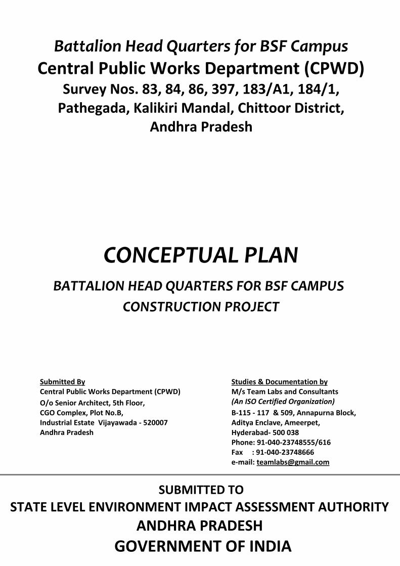
2.2 PROJECT DESCRIPTION2.2.1 DESIGN STAGEThe design of the layout and the buildings is planned based on the low impactdevelopment principles; mixed type road network/circulation network, improvedHydrology, open area, rain water harvesting structures, sewage treatment plant, refusesegregation and recycling of treated water, energy conservation by adopting highefficiency lighting fixtures and equipments, use of renewable energy systems like solarenergy systems etc., and water-efficient land scaping. The land allocation and the Builtup areas proposed are presented in table 2.1.
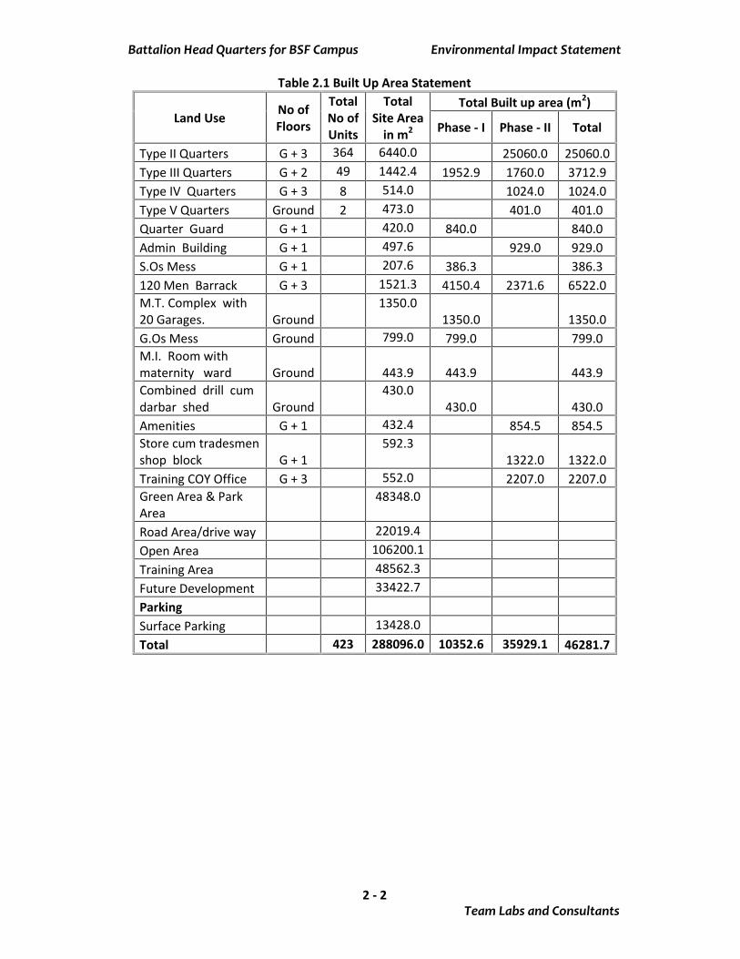
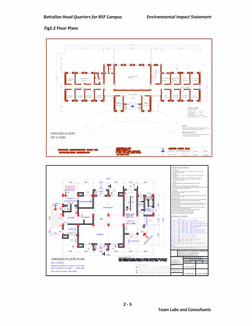
The amenities proposed include DG sets and STP. The water requirement of the projectduring operation will be drawn from Bore wells. Water recycling/reuse will be adoptedby way of using treated water for toilet flush systems with dual plumbing and green beltdevelopment. Runoff shall be managed by providing rain water harvesting pits toensure post development runoff will be less than the pre development run off from thesite. The required power will be drawn from the APTRANSCO and the energyrequirement will be optimized by adopting energy conservation measures efficientdesign for lighting. Solar Energy will be used by providing solar water heaters and SolarPhoto-Voltaic panels to cater to hot water requirements to the extent possible.Construction materials will be drawn from local sources to ensure low embodiedenergy. The layout of the project site and typical floor plan of buildings is presented infig. 2.1 and fig 2.2 respectively.
Battalion Head Quarters for BSF Campus Environmental Impact Statement
Team Labs and Consultants2 - 2
Table 2.1 Built Up Area Statement
Land Use No ofFloors
TotalNo ofUnits
TotalSite Area
in m2
Total Built up area (m2)
Phase - I Phase - II Total
Type II Quarters G + 3 364 6440.0 25060.0 25060.0Type III Quarters G + 2 49 1442.4 1952.9 1760.0 3712.9Type IV Quarters G + 3 8 514.0 1024.0 1024.0Type V Quarters Ground 2 473.0 401.0 401.0Quarter Guard G + 1 420.0 840.0 840.0Admin Building G + 1 497.6 929.0 929.0S.Os Mess G + 1 207.6 386.3 386.3120 Men Barrack G + 3 1521.3 4150.4 2371.6 6522.0M.T. Complex with20 Garages. Ground
1350.01350.0 1350.0
G.Os Mess Ground 799.0 799.0 799.0M.I. Room withmaternity ward Ground 443.9 443.9 443.9Combined drill cumdarbar shed Ground
430.0430.0 430.0
Amenities G + 1 432.4 854.5 854.5Store cum tradesmenshop block G + 1
592.31322.0 1322.0
Training COY Office G + 3 552.0 2207.0 2207.0Green Area & ParkArea
48348.0
Road Area/drive way 22019.4Open Area 106200.1Training Area 48562.3Future Development 33422.7ParkingSurface Parking 13428.0Total 423 288096.0 10352.6 35929.1 46281.7

Battalion Head Quarters for BSF Campus Environmental Impact Statement
Team Labs and Consultants2 - 3
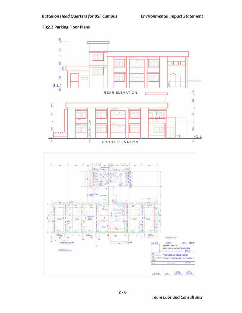
ParkingIt is proposed to provide Surface parking. The parking provision follows the guidelinesprescribed by FAR and Building policy of Andhra Pradesh. The number of parkingspaces provided is presented in table 2.2. The parking floor plans are presented in fig.2.3.
Table 2.2 Parking Space Provision of the ProjectFloor No. of units 4 - Wheeler 2 - Wheeler
Surface Parking 423 446 500Total 423 446 500Parking Details:Required Parking as per Go 168, GoAP 10182.0Parking Provided 13428.0 29.0%Required Parking as per MoEF & NBC 423Parking Provided 446
Table 2.3 Generated Traffic - Volume/Capacity Ratio
RoadExistingvolume,PCU/hr
Maximumcapacity,PCU/hr
Volume/Capacity Los,performance
Pathegada road 24 1800 0.013 “A” Excellent
MODIFIED LOS & PERFORMANCE
RoadExistingVolume,PCU/hr
ExistingVolume/capacity
AdditionalVolume
ModifiedVolume
ModifiedVolume/capacity*
Modified LOS&
PerformancePathegada road 24 0.013 125 149 0.083 “A” Excellent
*Traffic Volumes as PCU during Peak hour
Battalion Head Quarters for BSF Campus Environmental Impact Statement
Team Labs and Consultants2 - 4
Fig 2.1 Site plan
BSF10
BSF12
BSF13
BSF14
BSF15
BSF16
BSF18
BSF19
BSF20 B
SF21
BSF22
BSF25
BSF1
BSF2
BSF3
BSF4
BSF6
BSF7
BSF8
BSF9
BSF17
469.05
58.1
3290.93
55.77 40.54
164.17
30.19
154.
91
88.2
8
62.39
163.
46
46.32
37.53
70.38
117.15
177.79
31.47 82.92
56.46
24.4
8
24.75
93.55
105.30
139.40
BSF23
SH
EET RO
CK AR
EA
PITPIT
PIT
PIT
PIT
PIT
PIT
PIT
PIT
PITPIT
CH
ECK D
AM
PYLON
PYLON
HT PO
WER LINE
PIT
NA
LA
BU
ND
NA
LA
NALANALA
BUND
CH
ECK D
AM
EXISTING BT ROAD
ROAD CONECTING NH 205.
(KALIKIRI)
To NAYUNICHERUVUPALLE
CONNECTING TO NH 18
NALA
PITPIT
WELL
HT PO
WER LINE N
EW
S
NO
TESALL D
IMEN
SIO
NS A
RE IN
MTS
.
ON
LY WR
ITTEN D
IMEN
SIO
NS S
HALL B
E FOLLO
WED
.
ALL D
IMEN
SIO
NS S
HALL B
E CH
ECKED
AT S
ITE.
AR
CH
ITECT
SR
.AR
CH
ITECT
CH
IEF.AR
CH
ITECT
A.R
AJA
VARM
AN
SR
.AR
CH
ITECT(V
JA)
CPW
D G
POA
BU
ILDIN
GA
UTO
NA
GAR
,VIJA
YAW
AD
A
DA
TE:OCT'15 PR
OPO
SED
BSF C
OM
PLEX A
TKALIG
IRI,PA
THEG
AD
AC
HITTU
R (D
IST.) (A
.P)
EXISTING
HT PO
WER LINE
TO BE SHIFTED
SUITABLY
DEA
LT BY
MASTER
LAY O
UT PLA
ND
RG
NO
.134/SA(V
JA)/BS
F/LOP/9 R
V 5S
CA
LE - 1:2000
GO'S MESS
BSF11
163.
46
46.32
CH
ECK D
AM
BUND
SO's M
ESS
L.O.P.
DES
CR
EPAN
CY IF A
NY IN
DIM
ENSIO
NS S
HALL B
E BRO
UG
HT TO
THE N
OTIC
E OF S
ENIO
R A
RC
HITEC
T(VJA
)/CPW
D/V
IJAYA
WAD
A
T-IVB
SF5
Nala 0.38 acre
BSF24
Pit
(Boulders)
Bore
Bore
Sheet Rock
HIL
LY
TE
RR
AIN
Checkdam
Suitable for B
uildings
Suitable for
Steep Slopes
6.83 Acres
SC
HED
ULE O
F AC
CO
MM
OD
ATIO
N O
F QRTS
TYPE -II
TYPE -III
TYPE -V
49
19/1
8
BY TH
E DY.C
OM
MAN
DEN
T (ARC
H),Engg.B
r.B.S
.F.,NEW
DELH
I
19/219/3
19/4
19/5 19/6
19/7
19/8
19/9
19/10
19/11
19/12
19/13
19/15
19/16
19/17
19/18
19/19
19/20
19/2119/22
19/2319/24
AD
M. B
LOCK
THIS
MASTER
L.O.P. IS
PREPA
RED
AS PER
REQ
UIS
ITION
REC
EIVED
FRO
M S
RI.A
.K.TYA
GI,C
OM
MAN
DAN
T (AR
CH
),BSF,N
EW D
ELHI-3
VID
E HIS
LT.NO
.132/1/2012-ENG
G/B
SF/16174-77 D
T.31/12/12.
AN
D A
S PER
REQ
UIS
ITION
REC
IEVED
FRO
M TH
E DIG
(W), B
SF,
(ENG
G. B
RAN
CH
),NEW
DELH
I-3 VID
E HIS
LT. NO
.
109/01/2012-ENG
G/B
SF/14829-35. D
T.4/12/12.
S.N
O.Q
RT.TYPE.
REQ
UIR
EDPR
OVID
EDFU
TURE
1234
TYPE -IV8 358
2
358
49
6
2
NO
TE-
6
LEGEN
D
PRO
POSED
RES
. QR
TS
FUTU
RE R
ES. Q
RTS
THIS
MASTER
LAYO
UT PLA
N H
AS B
EEN PR
INCIPA
LLY APPR
OVED
VID
E HIS
LT.NO
.132/12/2012-ENG
G/B
SF/7431-33, D
T.01-04-2013.
THIS
MASTER
L.O.P. IS
PREPA
RED
AS PER
THE A
PPRO
VED
MASTER
LAYO
UT PLA
N D
RG
.NO
; 9534/SA(S
Z)II/B
SF/592/2-(A
LT-1)
NO
TE-
PRO
POSED
BU
ILDIN
GS
APPR
OVA
L NO
TE
1 * POSITIO
N O
F QU
ARTER
GU
ARD
HAS B
EEN S
HIFTED
5.0 M
REV
ISIO
N N
OTE - D
ATED
25-5-2015
TOW
AR
DS N
OR
TH,D
UE TO
PRES
ENCE O
F LOCATIO
N O
F NALA
.D
UE TO
SH
IFTING
OF Q
UAR
TER G
UAR
D ,TH
E LOC
ATIO
N O
F AD
MIN
BLO
CK &
APPR
OAC
H R
OAD
ARE A
LSO
MO
DIFIED
AS D
ISCU
SSED
WITH
E.E.& A
S D
ECID
ED IN
THE S
ITE MEETIN
G O
N 22-5-2015.
2*LOC
ATIO
N O
F B.S
.F LAY-O
UT H
AS B
EEN R
E-ALIG
NED
AN
DAN
D R
E-POSITIO
NED
/APO
RTIO
NED
DU
E TO S
URR
END
ERIN
G O
F
B.S
.F LAN
D TO
M.H
.A R
ESER
VE A
REA
AN
D A
NN
EXIN
G 19.19 A
CRES
OF LA
ND
FRO
M TH
E M.H
.A R
ESER
VED
AREA
.
MO
DIFIED
AREA
OF B
S F : -
71.19 Acres
AREA
STA
TEMEN
T
25.0 AC
RES
OF
* THIS
DR
AW
ING
SU
PERC
EDES
DRAW
ING
NO
.9534/SA(S
Z)II/B
SF/
592/2/R1. D
ATED
APR
IL 2013.
3* THIS
REV
ISED
DRAW
ING
LAY-O
UT H
AS B
EEN PR
EPARED
AS PER
HAN
DIN
G A
ND
TAKEN
OVER
OF M
.H.A
RES
ERVE LA
ND
(SU
RREN
DER
ING
25.0 AC
RES
AN
D A
NN
EXIN
G 19.0 A
CRES
LAN
D FR
OM
M.H
.AR
ESER
VE LA
ND
) AS R
EQU
ESTED
BY FR
ON
TIER H
.Q (S
PECIA
LO
PERATIO
NS)B
SF,B
AN
GALO
RE, V
IDE LT N
O.B
SF/2015/751-52.
DATED
22-5-2015,
Buildings
ENTRY
WATC
H
TOW
ER
1.71 Acres
WATC
H
TOW
ER
PIT
WATC
H
TOW
ER
WATCH
TOW
ER
WATC
H
TOW
ERW
ATCH
TOW
ER
WATC
H
TOW
ER
WATC
H
TOW
ER
WATC
H
TOW
ER
WATC
H
TOW
ER
WATC
H
TOW
ER
WATCH
TOW
ER
WATC
H
TOW
ER
T-IV
STORES
Type-II
PAR
K
9 M W
IDE M
AIN R
OAD
GR
EEN
T-V
PARK
PAR
K
Type-II
PAR
KP
ARK
Type-II
Type-II
Type-II
Type-II
Type-II
Type-II
Type-II
LAWN
9 M W
IDE M
AIN ROAD
T-V
GREEN
PARK
120MEN
BRK
120MEN
BRK
9 M WIDE MAIN ROAD
GRO
UN
DGRO
UN
D
120MEN
BRK
TR
AIN
ING
AR
EA
EXIT
PARK
ING
LAWN
4.7.16 R5
6 M W
IDE RO
AD
6 M WIDE ROAD
I.T.B.P
I.T.B.P
NO
TE:-
THE
LOP
HA
S B
EE
N R
EV
ISE
D A
S P
ER
DIS
CU
SS
ION
HE
LD IN
THE
OFFIC
E O
F IG(A
DM
) ON
10/ 09 /2015 INTH
E P
RE
SE
NC
E O
F CO
MD
T. (AR
CH
), DC
(AR
CH
)A
ND
AC
(AR
CH
).
THIS
REV
LOP IS
PREPA
RED
AS PER
APPR
OVED
LOP D
RG
NO
:
11438/SAH
YD/B
SF/592/60/R
2
QU
ARTER
GU
ARD
SENTRYPOST
NALA
12 M W
IDE R
OAD
8 .0 M
PARKING
GREEN
GREEN
THE LO
CATIO
N O
F QU
ARTER
GU
ARD
HAS B
EEN R
ETAIN
ED A
S PER
REV
N0 1 D
T 15.10.15
THE O
LD LO
P DRG
NO
11438/ SA H
YD/ B
SF/592/60/R
1 AS TH
EBU
ILDIN
G IS
ALR
EAD
Y CO
NSTR
UCTED
6 M WIDE ROAD
semi perm
anent sheds
THE LO
CATIO
N O
F QU
ARTER
GU
ARD
HAS BEEN
RETAINED
AS PERREV
N02 D
T 06.11.15
THE O
LD LO
P DRG
TYPE QTR
S PO
SITIO
N C
HAN
GED
TO N
EW PLAIN
PLACE DUE TO
PRESENCE
TYPE QTR
S PO
SITIO
N C
HAN
GED
TO N
EW PLAIN
PLACE DUE TO
PREVIOUS
OF S
EMI PER
MAN
ENT S
HED
S A
ND
ALSO IN
MID
DLE O
F SLOPPY H
ILL
POSITIO
N IN
MID
DLE O
F SLOPPY H
ILL
T-III (G+2)
45.4
9
33.78
18.33
35.76 28.48
41.0
1
24.69 48.3
5
20.8056.33
26.3
0
33.34
97.8
0
155.92
286.95
87.49
85.47
65.26
50.1139.79
20.3
9
109.5380.48
58.96
82.91
131.83
392.
59
101.
78
103.00
PAR
KP
ARK
CO
MM
UN
ITY
/AMEN
ITY C
ENTR
E
M.I.R
OO
M
T-III (G+2)
T-III (G+2)
T-III (G+2)
REV
N03 D
T 30.11.15TH
IS M
ASTER
L.O.P. H
AS BEENFIN
ALIZ
ED&
PREPARED
BY THIS
OFFIC
E BASED
ON
THE M
ASTER LOP
REC
D.FR
OM
BSF H
Q U
ND
ER WH
ICHLETTER
NO
132/12/2012-ENG
G/AR
CH/BSF/17154-56
DATED
23.11.15
SAN
JEEV K
APU
R
S.K
.BASH
A
REV
N0:4 D
T. 30.11.15 LO
CATIO
N O
F DARBAR SH
ED CH
ANG
EDTH
IS DRG
IS REVISED AS
PER LT N
O.23(3)/2016/E.E/TPD
/444 DT.21.5.2016
REC
IEVED
FRO
M EX
ECU
TIVE EN
GIN
EER, TIR
UPA
TI PRO
JECT DIVISIO
N,CPW
D TIRU
PATI.
REV
N0:5 D
T. 4.7.16
LOCATIO
N O
F DARBAR /D
RILL S
HED
CH
ANG
ED AS PER FEASIBILITY
SEN
T BY A
E TPT. SD I.
Battalion Head Quarters for BSF Campus Environmental Impact Statement
Team Labs and Consultants2 - 5
Fig2.2 Floor Plans
ENTRY
LOBBY
EXCHANGEDIG FORWARDLINK
MAP DEPOT
BTRY CHARGING
A.C.(TECH) DC(IT)
CRYPTO
SIGNALCENTRE
SIGNALWORKSHOP
COY COMDRCOY COMDR COY COMDR
RECORD ROOMCOY RECORD
SI(AD/T)&SM STORE
1575 WD CORRIDOR
1650 WD CORRIDOR
1575 WD CORRIDOR
MULTIMEDIA ROOM
497.6 SQM
L.TLT.
G.TLT.
PANTRY
UP
GROUND FLOOR
SABITA SAHOO
ASST.ARCH.
ARCH.SCALE - 1:100
DATE-NOV.2011
ARCH.ASST. SAROJ CHIEF ARCH.
B.BOSESR. ARCH.
R.M.AGGARWAL
N
AREA CHART
COVERED AREA ------- 498 SQM
GROUND FLOOR -------
FIRST FLOOR ------- COVERED AREA ------- 428 SQM
TOTAL COVERED AREA ------- 926 SQM
95.5 SQM
10.33 SQM.
10.33 SQM. 10.75 SQM. 10.75 SQM. 10.10 SQM.
21.90 SQM. 10.33 SQM.
10.33 SQM.10.10 SQM. 10.75 SQM. 10.75 SQM.
10.35 SQM. 10.75 SQM. 10.75 SQM.
12.29 SQM. 12.29 SQM.
NOTE DRG. HAS BEEN MODIFIED IN ACCORDANCE WITH LT. NO.
132/09/2010-ENGG./BSF/19724-25 DT.18.10.2011
DRG. NO. - SA (VI)/685/B1/PD/03/R1
REVISION NOTE THIS DRG. HAS BEEN REVISED AS/ LETTER NO.132/09/11 ENGG./BSF/2766 ON DATED 29.2.2012.
1350
DINING HALL
BAR
TOILET
TOILET
OPEN COURTYARD
+ 600 MM LVL.
+ 300 MM LVL.
KITCHEN PANTRY
STORE
GENTS
ENT. LOBBY
MAIN E
NTRANCE
SERVICE ENTRY
36503650 3650 3650 3300 3850
4500
2250
4500
22050
1170
0
3650 3650 3650 3650 3300 3850
22050
2250
RAMP UP
COOKS ROOM
FLOWER BOX
FLO
WE
R B
OX
600
WC+600 LVL.
LOUNGE
WIDTH-1350TREAD-300RISER-150
2845
600
3150
+ 0 MM LVL.
1500
600
2355
3560
+575 MM LVL.
+550 MM LVL.
+575 MM LVL.
+550 MM LVL.
W
W
JL
W
1500
4800
GROUND FLOOR PLAN
WW
W
JL
W
W
JL 1V
V2V3
V1
EDED1
D1
D2D3
D2
D3D3
D3
D3
W
V2
W
+ 0 MM LVL.
+ 600 MM LVL.
+ 2100 MM LVL.G D
230
2750
2750
500
UP1
6
11
1
6
11
15
SHAFT
SHAFT
SHAFT
1020
1020
9630/SA(SZ)II/592/4
THIS WORKING DRAWING HAS BEEN PREPARED BASED ON THE APPROVED PRELIMINARY
GROUND FLOOR PLAN
DEALT BY;
MARCH 2013.
K.ASHOK KUMAR
A.RAJAVARMAN
WORKING DRG
PROPOSED S.O.'S MESS & DORMITORYFOR B.S.F.,AT PATHEGADA,KALIGIRI,CHITTOOR, (A.P.)
SANJEEV KAPOOR.
SCHEDULE OF JOINERIES
S.NO. TYPE WIDTH HEIGHT
1 ED 1950 2550 GLAZED DOOR IN ALU.SECTIONS.
DESCRIPTION
2
3
D1 1000 2550
4
D2 900 2100
PVC DOOR
6W GLAZED WINDOW IN ALU. SECTIONS.
7
2000 1800
8
V 1200 900
9
V1
GLAZED LOUVERED VENTILATOR IN ALU. SECT.
5
SILL TOP
2100
2100750
1200 2100
SIZE
2550
2550
D3 800 2100
GLAZED/ PRL. LAM DOOR IN ALU.SECTIONS.
GLAZED/ PRL. LAM DOOR IN ALU.SECTIONS.PVC DOOR IN TOILETS
2550
W 1 1500 GLAZED WINDOW IN ALU. SECTIONS.1800 750 2550
940 -DO -
V2 900 -DO -
10 V3 600 -DO - -DO - -DO -
-DO -
-DO -
-DO - -DO -
-DO - -DO -
11 2750 RCC JALLI WORK
12 JL1 1430 -DO - -DO - -DO - -DO -
JL 1800
-DO -
750 2550
12 G D 800 1950 150 2100 M S GRILLE DOOR IN RCC FRAME
BRIEF SPECIFICATIONS STRUCTURE :RCC FRAMED STRUCTURE WITH FLY ASH BRICK OR HOLLOW C.C. BLOCKMASONRY FILLER WALLS.FLOORING :ENTRANCE HALL , STAIRCASE :--SHALL BE OF POLISHED MARBLE STONEFLOORING.ENTRANCE CANOPY FLOOR:---C.C. TILE DECORATIVE TILE FLOORING.
TOILETS :NON-SKID CEREMIC TILE FLOORING (HINDWARE OR EQVNT.)
ALL OTHER ROOMS,CORRIDORS;---DOUBLY CHARGED FULL BODYVITRIFIED TILE FLOORING.
DOORS :MAIN DOOR :--GLAZED PANELS IN ALUMINIUM SECTIONS.ALL OTHER DOORS :-- ALUMINIUM SECTIONS WITH PRELAMINATED PARTICLE.BOARD PANEL/GLAZED PANEL INSERTS.
WINDOWS :ALL WINDOWS ;-- GLAZED PANELS IN ALUMINIUM SECTIONS.WITH M.S. SECURITY GRILL.
VENTILATORS :ALL VENTILATORS ;-- FROSTED GLAZED PANELS IN ALUMINIUM SECTIONS.WITH M.S. SECURITY GRILL.
INTERIOR FINISH :HERITAGE GRANULE FINISH AT ENTRANCE LOBBY,LOUNGE,DINING AREAS.REST OF THE PLACES SHALL HAVE ACRYLIC EMULSION PAINT.EXTERIOR FINISH :30% (OR) BLANK WALLS SHALL HAVE HERITAGE FLAKES,TEXTURED FINISHREMAINING WALLS SHALL HAVE EXTERIOR ACRYLIC EMULSION PAINT.MISC. PROVISIONS :LOW WATER CONSUMPTION FLUSHING CISTERN(HIND WARE OR EQVNT)AUTOMATIVE FLUSHING URINAL SYSTEM.2% COST FOR LANDCAPING PROVISION SHALL BE PROVIDED.FIRE FIGHTING PROVISIONS SHALL BE PROVIDED.GREEN BUILDING NORMS SHALL BE FOLLOWED.LOW VOC PAINT PROVISIONS SHALL BE MADE.
NO; SA VI/689/12/SO's/PD/64.WHICH IS SENT BY BSF,HQ,NEW DELHI.
NOTE
GROUND FLOOR BUILT-UP AREA = 207.57 SQMFIRST FLOOR BUILT-UP AREA = 178.69 SQM
TOTAL BUILT-UP AREA = 386.26 SQM
2170
REVISION NOTE - 1
X
X
AREA STATEMENT :
Battalion Head Quarters for BSF Campus Environmental Impact Statement
Team Labs and Consultants2 - 6
Fig2.3 Parking Floor Plans
900
R E A R E LE V A T IO N
1200
600
3300
3300
3000
300
G .L .
1000
1800
+ 6 00 m m
+ 5 00 m m
+ 0 m m
750
F R O N T E LE V A T IO N
+ 5 00 m m
600
3300
3300
G .L .
1000
3000
300
600
3300
3300
G .L .
R C C F IN S / JA LLYA S P E R D E T A ILS .
R C C F IN S / JA LLYA S P E R D E T A ILS .
R C C F IN S / JA LLYA S P E R D E T A ILS .
750
300
600
113
ADVANCE COPY
W. DRG.
BATH1500X1200
BATH1500X1200
BATH1500X1200
BATH120000X1085
WASHINGAREA1430X1315
BARRACK5000X9620
UP DN
BALCONY1500 MM WIDE
BATH1500X1200
BATH1500X1200
BATH1500X1200
BATH1200X1085
WASHINGAREA
1430X1315
CUT OUT
W.C.1200X900
W.C.1200X900
BARRACK5000X9620
BARRACK5000X9620
BARRACK5000X9620
BARRACK5000X9620
DRYING AREA
TOILET6990X5145
TOILET6990X5145
STORE3000X3945
NCO3000X3945
5605
39475
13810
1008
0
FIRST FLOOR PLANCOVERED AREA =515.63 SQMT.
PARAPET WALLWITH JALI
DW1 DW1 DW1
D5
D5
D5D5
D5
D5
D5
D5
D5
D5
D5
W1W1
W1
W1W1
D1
D3
D3
D1
SW
5970
V1
V1
V1
V1
V1
V1
V1
V1
V1
V1
A
A
W.C.1200X900
W.C.1200X900
W.C.1200X900
W.C.1200X900
W.C.1200X900
W.C.1200X900
W1 W1 W1 W1 W1 W1 W1
BALCONY1500 MM WIDE
BALCONY1500 MM WIDE
W1
RAILING
A B C D E F G H J K L M N O
1
3
4
5
2
3420 2295 720 2850 925 875 2900 1380 1635
5375
5375
6200
4025
5825
4420 602057156020
715
1130
900
1130
1500
1130
900
1130
900
600
1015
900
1130
900
1500
900
1130
900
1015
1015
900
1130
900
1500
900
1130
900
1015
1015
900
1130
900
1500
900
1130
900
1015
600
1015
900
1130
900
1500
900
1130
900
1015
600
1015
900
1130
900
1500
900
1130
900
1015
1015
900
1130
900
1500
900
1130
900
1015
600
1800
400
1500
670
1545 1545
1430
3795
5000
9620
600
115
115
5000
9620
9620
50003000
3945
3000
3945
6125
3660
5000
9620
5000
9620
5795600600
1570
2400
510
970
1005960555 1005
600 715
600
600
715
1500
6395
1500
61656395
1500
1500 930 1500
1200
1500
1200
3795
1430
600 600
23060
015
0
600
415
600
415
600
415
600
514
150
415
415
514
230
415
E.D.B
1200
799
230 230 230
eq eq
230
V1 V1
projection abovechhajja
55511
5
670
150150
5495
W1W1
750 750
420
230W1 W142
0
230
600
420
600
600
420
600
w3 w2 w3w2
REFFER DETAIL.DRG.
JALI
CANOPY
eq. eq.900 850650 eq. 900 eq. eq. eq. eq. eq.1000 eq. eq.900
R.W.P.
R.W.P.
R.W.P.
R.W.P.
150
225 225
6680
300 300
(REFER DETDRG)
RA
ILIN
G
900
R.W.P.
1500
ASST.ARCHITECT ARCHITECT SENIOR ARCHITECT?????? ????????. ??? ?????
???????????? ???????CHIEF ARCHITECT
??? ?? ???????
????? ? ???
????? :
?????? :DATE : SEP 2015
? ???? ??:
? ??? ? :DEALT :
?????? ??-REV NO -
A.Rajavarman Sanjeev kapur
S.NO DATE REVISION DEALT CHECKEDS.NO DATE REVISION DEALT CHECKEDS.NO DATE REVISION DEALT CHECKEDS.NO DATE REVISION DEALT CHECKED
FILE NO :
FIRST FLOOR PLAN
SCALE - 1:100
?????? ??????? , ? ?.??.?? ??
5th FLOOR CPWD CGO COMPLEX AUTO NAGAR VIJAYAWADA
PROPOSED 12O MEN BARRACK
FOR B.S.F., AT KALIGIRI., CHITTORE A.P

Battalion Head Quarters for BSF Campus Environmental Impact Statement
Team Labs and Consultants2 - 7
2.2.1.1 Storm water drains:Conservation of water resource is most important aspect of the project duringconstruction and occupation phases. Storm water drainage planning, domestic waterplanning and sewerage transfer and sewage treatment planning are critical aspects ofconstruction and occupation stages of projects.
Storm water drains will be provided along the roads to meet the expected increase inthe runoff during rainy seasons due to the impervious nature of the roads and otherpaved areas. The site is uneven and it is proposed to maintain the levels as much aspossible, hence storm water let outs from the site are anticipated. The expected runoffis calculated for the design of the storm water runoff and presented in following table.
CALCULATION FOR STORM WATER DRAIN:(a) With out project:Area of Catchment, ‘A’ : 28.7112 HaRun off Coefficient, ‘C’ : 0.6Maximum intensity of rainfall, ‘I’ : 40 mm/hrTherefore Q : 1.914 m3/sec
(b) With project: :Area for catchment for roof and road : 3.715 Ha
Area of Catchment, ‘A’ : 3.715 HaRun off Coefficient, ‘C’ : 0.9Maximum intensity of rainfall, ‘I’ : 40 mm/hrTherefore Q = : 0.372 m3/sec
Area for catchment for open areas : 24.996 HaRun off Coefficient, ‘C’ : 0.6Maximum intensity of rainfall, ‘I’ : 40 mm/hrTherefore Q = : 1.666 m3/secTotal Discharge : 2.038 m3/secBut, Discharge, Q = A/V :Where, :A= Area of the Drain, :V= Max. Permissible Velocity : 6 m/sec for concrete drain
Area of drain, ‘A’ = Q/V : 0.340 m2
Taking depth of drain as 0.6 m at the startingpoint : 0.6Width of drain = Area/depth = 0.566 m 566 mm
Width of the drain is to taken 566 mm and depth varies according to the slope ofground.

Battalion Head Quarters for BSF Campus Environmental Impact Statement
Team Labs and Consultants2 - 8
Table 2.4 Strom Water Runoff
Land Use Area inHectares
Vol./hr(KL) afterdevelopment
C=0.8
Vol./hr (KL)before
developmentC=0.6
Difference inDischarges
Roof Area 1.51 484.2 363.1 121.0Road Area 2.20 704.6 528.5 176.2Open Area 25.00 2999.5* 5999.1 -2999.5TOTAL 28.71 -2702.3
* C=0.3 after development of greenery
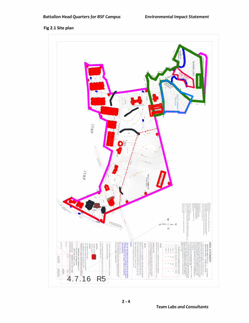
Typical drawings of intermediate rainwater harvesting pits is presented in Figure 2.4
Fig 2.4 Rainwater Harvesting Structure2.2.1.2 Domestic Water: It is proposed to draw domestic water from the Bore well. Thewater requirement of the project during occupation stage is in the order of 328.3 KLD.The water requirement for the project during the occupation stage is presented in table2.5. The water savings for the project is presented in table 2.6.
Battalion Head Quarters for BSF Campus Environmental Impact Statement
Team Labs and Consultants2 - 9
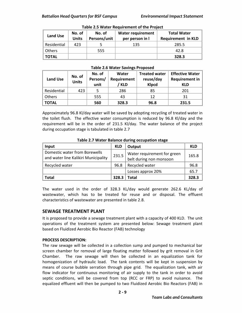
Table 2.5 Water Requirement of the Project
Land Use No. ofUnits
No. ofPersons/unit
Water requirementper person in l
Total WaterRequirement in KLD
Residential 423 5 135 285.5Others 555 42.8TOTAL 328.3
Table 2.6 Water Savings Proposed
Land Use No. ofUnits
No. ofPersons/
unit
WaterRequirement
/ KLD
Treated waterreuse/day
Klpcd
Effective WaterRequirement in
KLDResidential 423 5 286 85 201Others 555 43 12 31TOTAL 560 328.3 96.8 231.5
Approximately 96.8 Kl/day water will be saved by adopting recycling of treated water inthe toilet flush. The effective water consumption is reduced by 96.8 Kl/day and therequirement will be in the order of 231.5 Kl/day. The water balance of the projectduring occupation stage is tabulated in table 2.7
Table 2.7 Water Balance during occupation stageInput KLD Output KLDDomestic water from Borewellsand water line Kalikiri Municipality 231.5 Water requirement for green
belt during non monsoon165.8
Recycled water 96.8 Recycled water 96.8Losses approx 20% 65.7
Total 328.3 Total 328.3
The water used in the order of 328.3 KL/day would generate 262.6 KL/day ofwastewater, which has to be treated for reuse and or disposal. The effluentcharacteristics of wastewater are presented in table 2.8.
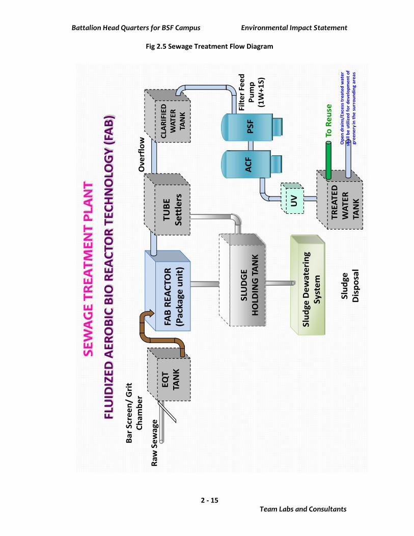
SEWAGE TREATMENT PLANTIt is proposed to provide a sewage treatment plant with a capacity of 400 KLD. The unitoperations of the treatment system are presented below: Sewage treatment plantbased on Fluidized Aerobic Bio Reactor (FAB) technology
PROCESS DESCRIPTION:The raw sewage will be collected in a collection sump and pumped to mechanical barscreen chamber for removal of large floating matter followed by grit removal in GritChamber. The raw sewage will then be collected in an equalization tank forhomogenization of hydraulic load. The tank contents will be kept in suspension bymeans of course bubble serration through pipe grid. The equalization tank, with airflow indicator for continuous monitoring of air supply to the tank in order to avoidseptic conditions, will be covered from top (RCC or FRP) to avoid nuisance. Theequalized effluent will then be pumped to two Fluidized Aerobic Bio Reactors (FAB) in
Battalion Head Quarters for BSF Campus Environmental Impact Statement
Team Labs and Consultants2 - 10
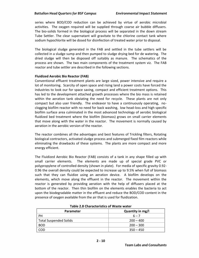
series where BOD/COD reduction can be achieved by virtue of aerobic microbialactivities. The oxygen required will be supplied through coarse air bubble diffusers.The bio-solids formed in the biological process will be separated in the down streamTube Settler. The clear supernatant will gravitate to the chlorine contact tank wheresodium hypochlorite will be dosed for disinfection of treated water prior to disposal.
The biological sludge generated in the FAB and settled in the tube settlers will becollected in a sludge sump and then pumped to sludge drying bed for de watering. Thedried sludge will then be disposed off suitably as manure. The schematics of theprocess are shown. The two main components of the treatment system viz. The FABreactor and tube settler are described in the following sections.
Fluidized Aerobic Bio Reactor (FAB)Conventional effluent treatment plants are large sized, power intensive and require alot of monitoring. Scarcity of open space and rising land a power costs have forced theindustries to look our for space saving, compact and efficient treatment options. Thishas led to the development attached growth processes where the bio mass is retainedwithin the aeration tank obviating the need for recycle. These plants are not onlycompact but also user friendly. The endeavor to have a continuously operating, no-clogging biofilm reactor with no need for back washing, low head-loss and high specificbiofilm surface area culminated in the most advanced technology of aerobic biologicalfluidized bed treatment where the biofilm (biomass) grows on small carrier elementsthat move along with the water in the reactor. The movement is normally caused byaeration in the aerobic version of the reactor.
The reactor combines all the advantages and best features of Trickling filters, Rotatingbiological contractors, activated sludge process and submerged fixed film reactors whileeliminating the drawbacks of these systems. The plants are more compact and moreenergy efficient.
The Fluidized Aerobic Bio Reactor (FAB) consists of a tank in any shape filled up withsmall carrier elements. The elements are made up of special grade PVC orpolypropylene of controlled density (shown in plate). For media of specific gravity 0.92-0.96 the overall density could be expected to increase up to 9.5% when full of biomasssuch that they can fluidize using an aeration device. A biofilm develops on theelements, which move along the effluent in the reactor. The movement within thereactor is generated by providing aeration with the help of diffusers placed at thebottom of the reactor. Then thin biofilm on the elements enables the bacteria to actupon the biodegradable matter in the effluent and reduce the BOD/COD content in thepresence of oxygen available from the air that is used for fluidization.
Table 2.8 Characteristics of Waste waterParameter Quantity in mg/l
PH 6 – 7Total Suspended Solids 200 – 400BOD 200 – 300COD 350 – 450
Battalion Head Quarters for BSF Campus Environmental Impact Statement
Team Labs and Consultants2 - 11
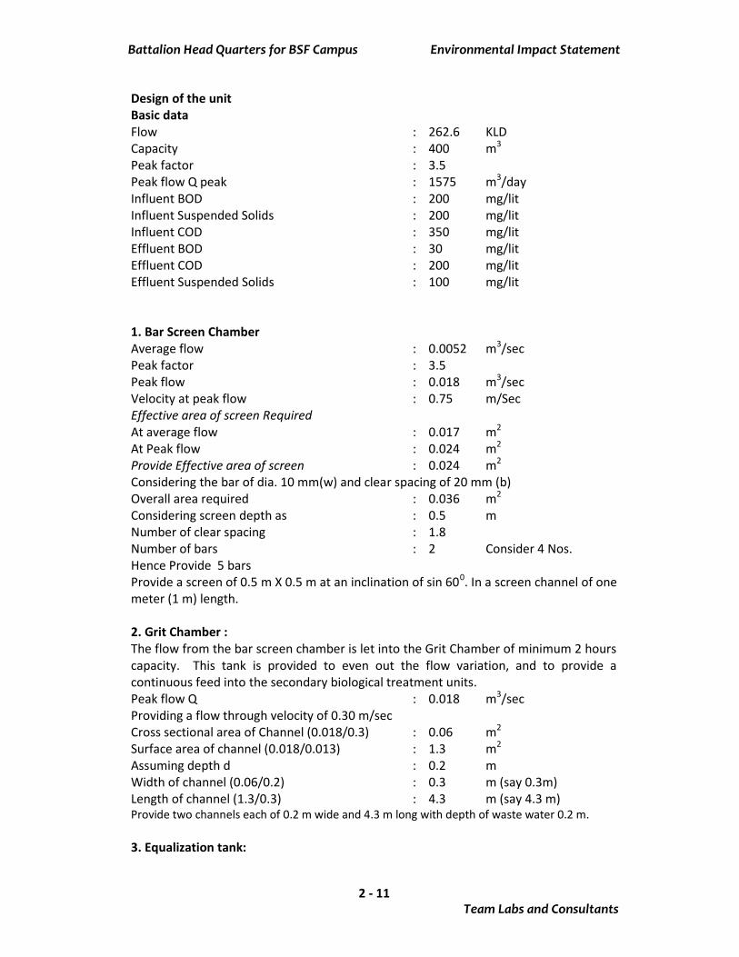
Design of the unitBasic dataFlow : 262.6 KLDCapacity : 400 m3
Peak factor : 3.5Peak flow Q peak : 1575 m3/dayInfluent BOD : 200 mg/litInfluent Suspended Solids : 200 mg/litInfluent COD : 350 mg/litEffluent BOD : 30 mg/litEffluent COD : 200 mg/litEffluent Suspended Solids : 100 mg/lit
1. Bar Screen ChamberAverage flow : 0.0052 m3/secPeak factor : 3.5Peak flow : 0.018 m3/secVelocity at peak flow : 0.75 m/SecEffective area of screen RequiredAt average flow : 0.017 m2
At Peak flow : 0.024 m2
Provide Effective area of screen : 0.024 m2
Considering the bar of dia. 10 mm(w) and clear spacing of 20 mm (b)Overall area required : 0.036 m2
Considering screen depth as : 0.5 mNumber of clear spacing : 1.8Number of bars : 2 Consider 4 Nos.Hence Provide 5 barsProvide a screen of 0.5 m X 0.5 m at an inclination of sin 600. In a screen channel of onemeter (1 m) length.
2. Grit Chamber :The flow from the bar screen chamber is let into the Grit Chamber of minimum 2 hourscapacity. This tank is provided to even out the flow variation, and to provide acontinuous feed into the secondary biological treatment units.Peak flow Q : 0.018 m3/secProviding a flow through velocity of 0.30 m/secCross sectional area of Channel (0.018/0.3) : 0.06 m2
Surface area of channel (0.018/0.013) : 1.3 m2
Assuming depth d : 0.2 mWidth of channel (0.06/0.2) : 0.3 m (say 0.3m)Length of channel (1.3/0.3) : 4.3 m (say 4.3 m)Provide two channels each of 0.2 m wide and 4.3 m long with depth of waste water 0.2 m.
3. Equalization tank:

Battalion Head Quarters for BSF Campus Environmental Impact Statement
Team Labs and Consultants2 - 12
The flow from the bar screen chamber is let into the equalization tank of minimum2hours capacity. This tank is provided to even out the flow variation, and to provide acontinuous feed into the secondary biological treatment units.Average flow : 18.75 m3/hrPeak factor : 3.5Peak flow : 65.6 m3/hrHydraulic retention tank = 2 hrs at Peak flowHence required volume of the tank : 131.25 m3
Provide tank of : 131.25 m3 CapacityAssuming depth : 5 mArea : 26.25 m2
Assuming length to width ratio (1:1) ; l=blength of the tank : 5.1 mwidth of the tank : 5.1 mAir required for agitation : 0.01 m3/ m2 minTotal air required : 78.75 m3/hrAir blower required : 100 m3/hr @ 3.8 mwcEffluent transfer pump : 18.75 m3/hr @ 8 mwc
4. Fluidized Aerobic Bio Reactor (FAB):The polypropylene media have been provided with a specific surface area of 350 – 520m2 /m3. This allows micro-organisms to get attached and biomass concentration canbe increased to four folds as compared to Activated Sludge Process. This enables toconsider higher Organic loading rates.
The micro-organisms attached to media are kept in a fluid state thereby maintainingthe CSTR (continuous Stirrer tank reactor) regime as well as two tanks are provided inseries making the plug – flow system. This will enhance the efficiencies and have themerits of both CSTR and plug-flow regimes.Organic loading rate : 3.2 kg BOD/ m3 dOrganic load : 90 kg/dayVolume of the tank : 28.12 m3
Assume the depth : 5 mNo. of tanks in series : 2Size of the tank : 2.6 m dia. x 5.0 SWDSpecific gravity of media : 0.92 to 0.96Specific surface area of media : 350 – 520 m2 /m3
Media filling : 30 – 50 % of tank volumeOxygen required : 2 kg / kg BODOxygen in air : 23%Specific gravity of air @ 30 deg. : 1.65Aeration : Coarse bubbleOxygen transfer efficiency : 12%Air required : 116.6 m3/hrAir blower required : 150 m3/hr @ 6.5 m wc
5.Tube settlerSurface loading rate : 48 m2 /m3 d
Battalion Head Quarters for BSF Campus Environmental Impact Statement
Team Labs and Consultants2 - 13
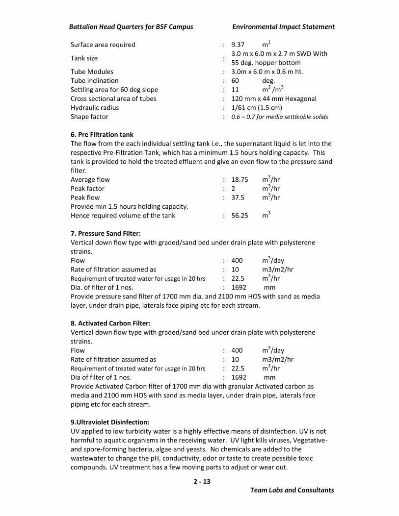
Surface area required : 9.37 m2
Tank size : 3.0 m x 6.0 m x 2.7 m SWD With55 deg. hopper bottom
Tube Modules : 3.0m x 6.0 m x 0.6 m ht.Tube inclination : 60 deg.Settling area for 60 deg slope : 11 m2 /m3
Cross sectional area of tubes : 120 mm x 44 mm HexagonalHydraulic radius : 1/61 cm (1.5 cm)Shape factor : 0.6 – 0.7 for media settleable solids
6. Pre Filtration tankThe flow from the each individual settling tank i.e., the supernatant liquid is let into therespective Pre-Filtration Tank, which has a minimum 1.5 hours holding capacity. Thistank is provided to hold the treated effluent and give an even flow to the pressure sandfilter.Average flow : 18.75 m3/hrPeak factor : 2 m3/hrPeak flow : 37.5 m3/hrProvide min 1.5 hours holding capacity.Hence required volume of the tank : 56.25 m3
7. Pressure Sand Filter:Vertical down flow type with graded/sand bed under drain plate with polysterenestrains.Flow : 400 m3/dayRate of filtration assumed as : 10 m3/m2/hrRequirement of treated water for usage in 20 hrs : 22.5 m3/hrDia. of filter of 1 nos. : 1692 mmProvide pressure sand filter of 1700 mm dia. and 2100 mm HOS with sand as medialayer, under drain pipe, laterals face piping etc for each stream.
8. Activated Carbon Filter:Vertical down flow type with graded/sand bed under drain plate with polysterenestrains.Flow : 400 m3/dayRate of filtration assumed as : 10 m3/m2/hrRequirement of treated water for usage in 20 hrs : 22.5 m3/hrDia of filter of 1 nos. : 1692 mmProvide Activated Carbon filter of 1700 mm dia with granular Activated carbon asmedia and 2100 mm HOS with sand as media layer, under drain pipe, laterals facepiping etc for each stream.
9.Ultraviolet Disinfection:UV applied to low turbidity water is a highly effective means of disinfection. UV is notharmful to aquatic organisms in the receiving water. UV light kills viruses, Vegetative-and spore-forming bacteria, algae and yeasts. No chemicals are added to thewastewater to change the pH, conductivity, odor or taste to create possible toxiccompounds. UV treatment has a few moving parts to adjust or wear out.
Battalion Head Quarters for BSF Campus Environmental Impact Statement
Team Labs and Consultants2 - 14
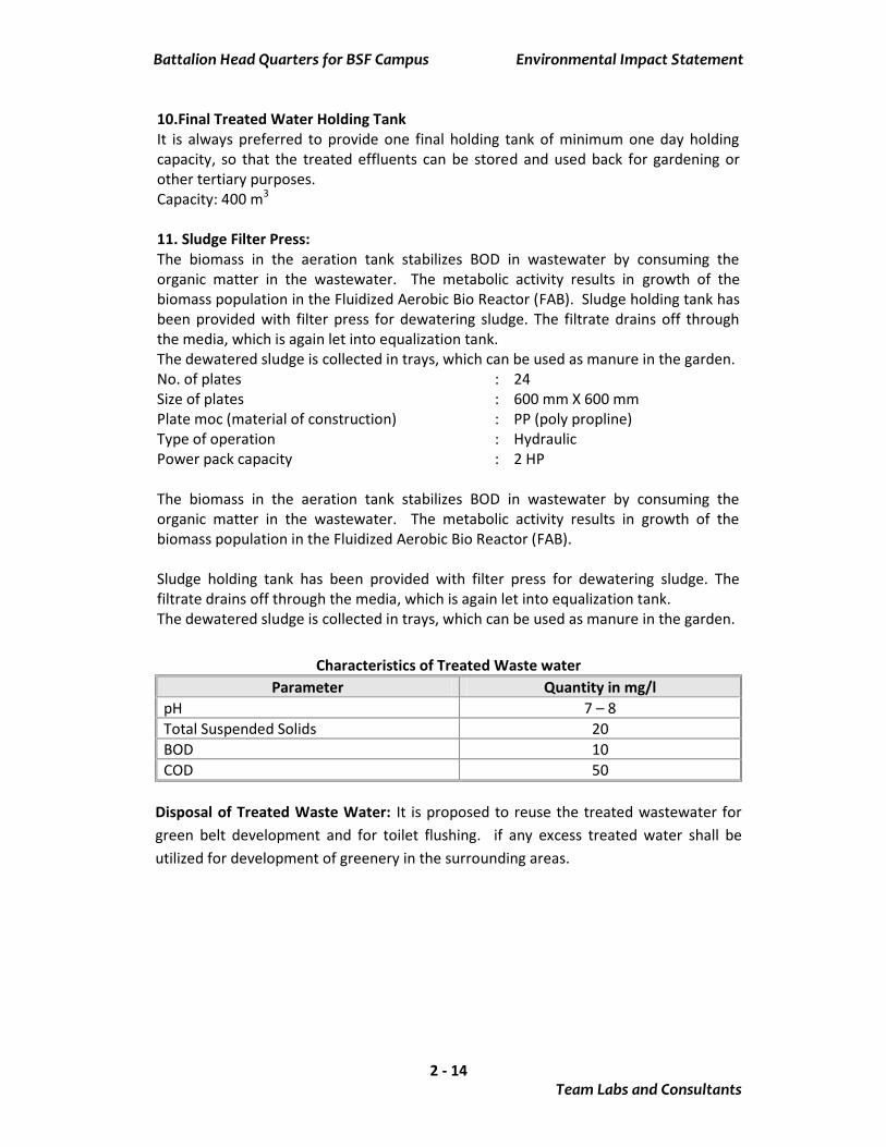
10.Final Treated Water Holding TankIt is always preferred to provide one final holding tank of minimum one day holdingcapacity, so that the treated effluents can be stored and used back for gardening orother tertiary purposes.Capacity: 400 m3
11. Sludge Filter Press:The biomass in the aeration tank stabilizes BOD in wastewater by consuming theorganic matter in the wastewater. The metabolic activity results in growth of thebiomass population in the Fluidized Aerobic Bio Reactor (FAB). Sludge holding tank hasbeen provided with filter press for dewatering sludge. The filtrate drains off throughthe media, which is again let into equalization tank.The dewatered sludge is collected in trays, which can be used as manure in the garden.No. of plates : 24Size of plates : 600 mm X 600 mmPlate moc (material of construction) : PP (poly propline)Type of operation : HydraulicPower pack capacity : 2 HP
The biomass in the aeration tank stabilizes BOD in wastewater by consuming theorganic matter in the wastewater. The metabolic activity results in growth of thebiomass population in the Fluidized Aerobic Bio Reactor (FAB).
Sludge holding tank has been provided with filter press for dewatering sludge. Thefiltrate drains off through the media, which is again let into equalization tank.The dewatered sludge is collected in trays, which can be used as manure in the garden.
Characteristics of Treated Waste waterParameter Quantity in mg/l
pH 7 – 8Total Suspended Solids 20BOD 10COD 50
Disposal of Treated Waste Water: It is proposed to reuse the treated wastewater forgreen belt development and for toilet flushing. if any excess treated water shall beutilized for development of greenery in the surrounding areas.
Battalion Head Quarters for BSF Campus Environmental Impact Statement
Team Labs and Consultants2 - 15
Fig 2.5 Sewage Treatment Flow Diagram
SEW
AG
E TR
EATM
ENT
PLA
NT
FLU
IDIZ
ED A
ERO
BIC
BIO
REA
CTO
R TE
CHN
OLO
GY
(FA
B)
Slud
geD
ewat
erin
gSy
stem
EQT
TAN
K
ACF
BarS
cree
n/ G
ritCh
ambe
r
Raw
Sew
age
Ove
rflo
w
Filte
r Fee
dPu
mp
(1W
+1S)
Slud
geD
ispo
sal
SLU
DG
EH
OLD
ING
TAN
K
CLAR
IFIE
DW
ATER
TAN
K
FAB
REAC
TOR
(Pac
kage
uni
t)TU
BESe
ttle
rs
PSF
TREA
TED
WAT
ERTA
NKUV
To R
euse
Ope
n dr
ains
/Exc
ess t
reat
ed w
ater
shal
l be
utili
zed
for d
evel
opm
ent o
fgr
eene
ry in
the
surr
ound
ing
area
s

Battalion Head Quarters for BSF Campus Environmental Impact Statement
Team Labs and Consultants2 - 16
2.2.1.3 Solid Waste (Municipal Solid Waste Composition)In India the biodegradable portion dominates the bulk of Municipal Solid Waste.Generally the biodegradable portion is mainly due to food and yard waste. The table 2.9presents Composition of Municipal Solid Waste.
Table 2.9 Composition of Municipal Solid WasteType Composition (%) Solid waste in kg
Paper 8 98Plastics 9 110Metals 1 12Glass 1 12others 4 49Biodegradable 48 588Inerts 25 306Rags 4 49Total 100 1224
(Source: NSWAI- National Solid Waste Association of India estimate)
Design StageThe total number of people anticipated to stay in the project is in the range of 2500 –3000. The anticipated solid waste/garbage is in the range of 500 g/head, and the totalgarbage will be in the order of 1224 kg/day. The present practice is to collect thegarbage from each house using the services of NGO’s and send it to the segregationpoint by cycle-rickshaws. The biodegradable garbage after segregation is composted atthe segregation point and the remaining waste is sent to the landfill. The landfill site isyet to obtain clearance under Municipal solid waste rules of MoE&F, GOI. The table2.10 presents the anticipated garbage quantity after occupation. The responsibility ofgarbage collection and disposal lies with the Municipality, however the projectauthorities propose to educate the residents to segregate the waste at source beforedisposal.
Table 2.10 Solid Waste Generation
Land Use No. ofUnits
No. of Persons/unit
Total No. ofPersons
Total Solid waste inKgs @ 0.5 kg/head
Residential 423 5 2115 1058Others 555 555 167TOTAL 1224
Vermi composting:About 40% of the solid waste contains biodegradable waste. The biodegradable wastecontains food waste along with other waste. Vermi Composting can be used to convertthis biodegradable waste into a valuable commodity. It is proposed to provide about300 m2 area for Vermi composting with typical size of 5m X 3 m X 0.5 m. The tank shallbe divided into four chambers by a wall containing gaps to facilitate aeration as well asmigration of earthworms from one chamber to another chamber. The covers of thechambers can be screwed in case of any emergency or if the compost has to be
Battalion Head Quarters for BSF Campus Environmental Impact Statement
Team Labs and Consultants2 - 17
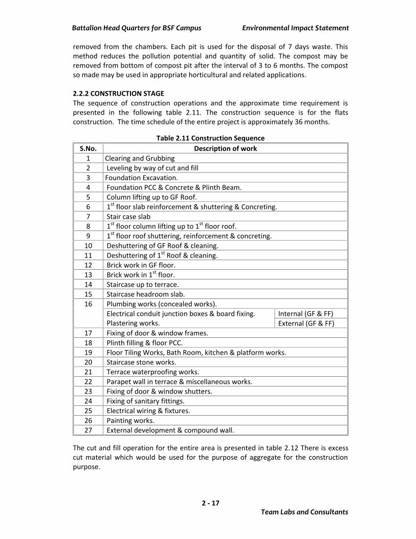
removed from the chambers. Each pit is used for the disposal of 7 days waste. Thismethod reduces the pollution potential and quantity of solid. The compost may beremoved from bottom of compost pit after the interval of 3 to 6 months. The compostso made may be used in appropriate horticultural and related applications.
2.2.2 CONSTRUCTION STAGEThe sequence of construction operations and the approximate time requirement ispresented in the following table 2.11. The construction sequence is for the flatsconstruction. The time schedule of the entire project is approximately 36 months.
Table 2.11 Construction SequenceS.No. Description of work
1 Clearing and Grubbing2 Leveling by way of cut and fill3 Foundation Excavation.4 Foundation PCC & Concrete & Plinth Beam.5 Column lifting up to GF Roof.6 1st floor slab reinforcement & shuttering & Concreting.7 Stair case slab8 1st floor column lifting up to 1st floor roof.9 1st floor roof shuttering, reinforcement & concreting.
10 Deshuttering of GF Roof & cleaning.11 Deshuttering of 1st Roof & cleaning.12 Brick work in GF floor.13 Brick work in 1st floor.14 Staircase up to terrace.15 Staircase headroom slab.16 Plumbing works (concealed works).
Electrical conduit junction boxes & board fixing.Plastering works.
Internal (GF & FF)External (GF & FF)
17 Fixing of door & window frames.18 Plinth filling & floor PCC.19 Floor Tiling Works, Bath Room, kitchen & platform works.20 Staircase stone works.21 Terrace waterproofing works.22 Parapet wall in terrace & miscellaneous works.23 Fixing of door & window shutters.24 Fixing of sanitary fittings.25 Electrical wiring & fixtures.26 Painting works.27 External development & compound wall.
The cut and fill operation for the entire area is presented in table 2.12 There is excesscut material which would be used for the purpose of aggregate for the constructionpurpose.
Battalion Head Quarters for BSF Campus Environmental Impact Statement
Team Labs and Consultants2 - 18
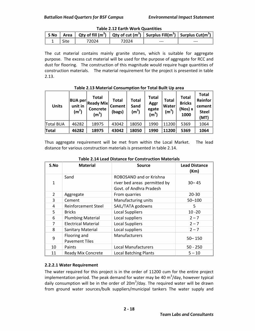
Table 2.12 Earth Work QuantitiesS No Area Qty of fill (m3) Qty of cut (m3) Surplus Fill(m3) Surplus Cut(m3)
1 Site 72024 72024 --- ---
The cut material contains mainly granite stones, which is suitable for aggregatepurpose. The excess cut material will be used for the purpose of aggregate for RCC anddust for flooring. The construction of this magnitude would require huge quantities ofconstruction materials. The material requirement for the project is presented in table2.13.
Table 2.13 Material Consumption for Total Built Up area
UnitsBUA perunit in
(m2)
TotalReady MixConcrete
(m3)
TotalCement(bags)
TotalSand(m3)
TotalAggregate(m3)
TotalWater(m3)
TotalBricks(Nos) x1000
TotalReinforcement
Steel(MT)
Total BUA 46282 18975 43042 18050 1990 11200 5369 1064Total 46282 18975 43042 18050 1990 11200 5369 1064
Thus aggregate requirement will be met from within the Local Market. The leaddistance for various construction materials is presented in table 2.14.
Table 2.14 Lead Distance for Construction MaterialsS.No Material Source Lead Distance
(Km)
1Sand ROBOSAND and or Krishna
river bed areas permitted byGovt. of Andhra Pradesh
30– 45
2 Aggregate From quarries 20-303 Cement Manufacturing units 50–1004 Reinforcement Steel SAIL/TATA godowns 55 Bricks Local Suppliers 10 -206 Plumbing Material Local suppliers 2 – 77 Electrical Material Local Suppliers 2 – 78 Sanitary Material Local suppliers 2 – 7
9 Flooring andPavement Tiles
Manufacturers 50– 150
10 Paints Local Manufacturers 50 - 25011 Ready Mix Concrete Local Batching Plants 5 – 10
2.2.2.1 Water RequirementThe water required for this project is in the order of 11200 cum for the entire projectimplementation period. The peak demand for water may be 40 m3/day, however typicaldaily consumption will be in the order of 20m3/day. The required water will be drawnfrom ground water sources/bulk suppliers/municipal tankers The water supply and
Battalion Head Quarters for BSF Campus Environmental Impact Statement
Team Labs and Consultants2 - 19
plumbing will be optimized and low water consuming faucets and flush tanks will beused to conserve water.
2.2.2.2 Construction DebrisThe construction debris consists of various types of materials. The construction debriswill be in both hazardous and non hazardous categories. The hazardous debris consistsof empty containers of adhesives, thinners, paints, petroleum products. These emptycontainers will be sold to authorized recyclers. The non hazardous wastes containrecyclable debris like iron and other metal, glass, plastics, cartons of paper, wood etc.These wastes will be sent for reuse/recycle. The waste percentage will be in the orderof 2%. Construction debris containing bricks, will be used for land grading/ in the placeof subgrade.
2.2.2.3 PaintsAll the paints used in the premises will be ensured to have an albedo of at least 0.4 toincrease the reflectivity and reduce the heat dissipation and heat island effects.
2.2.2.4 Work Force:The labor/work force requirement is approximately 8000 man days of various skilledand unskilled employees. Sufficient labor force and skilled employees are availablefrom the rural areas. The peak labor force requirement will be in the order of 100people and some of the labor force will be provided with temporary accommodationwithin the site. The labor force will be provided with a temporary toilet facilitiesconnected to a septic tank followed by soak pit. The labor accommodation will provideaccommodation to about 10 families. The water requirement for the labor force will beapproximately 3000 lt/day.
2.2.2.5 Material preparation and transportMost of the construction material including aggregate will be drawn from outside. Thematerial will be transported by trucks and the approximate number of truck tripsare200. The material transport within the site will be facilitated by required number oftippers. All grades of concrete will be procured from RMC suppliers. No stone crushershall be installed at site. Aggregate for Road, pavements and floorings shall be procuredthrough the metal suppliers in the required quantities.
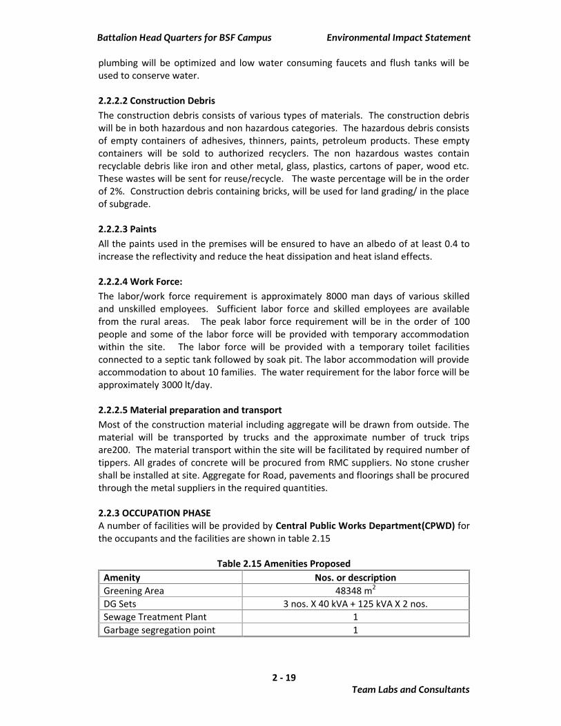
2.2.3 OCCUPATION PHASEA number of facilities will be provided by Central Public Works Department(CPWD) forthe occupants and the facilities are shown in table 2.15
Table 2.15 Amenities ProposedAmenity Nos. or descriptionGreening Area 48348 m2
DG Sets 3 nos. X 40 kVA + 125 kVA X 2 nos.Sewage Treatment Plant 1Garbage segregation point 1
Battalion Head Quarters for BSF Campus Environmental Impact Statement
Team Labs and Consultants2 - 20
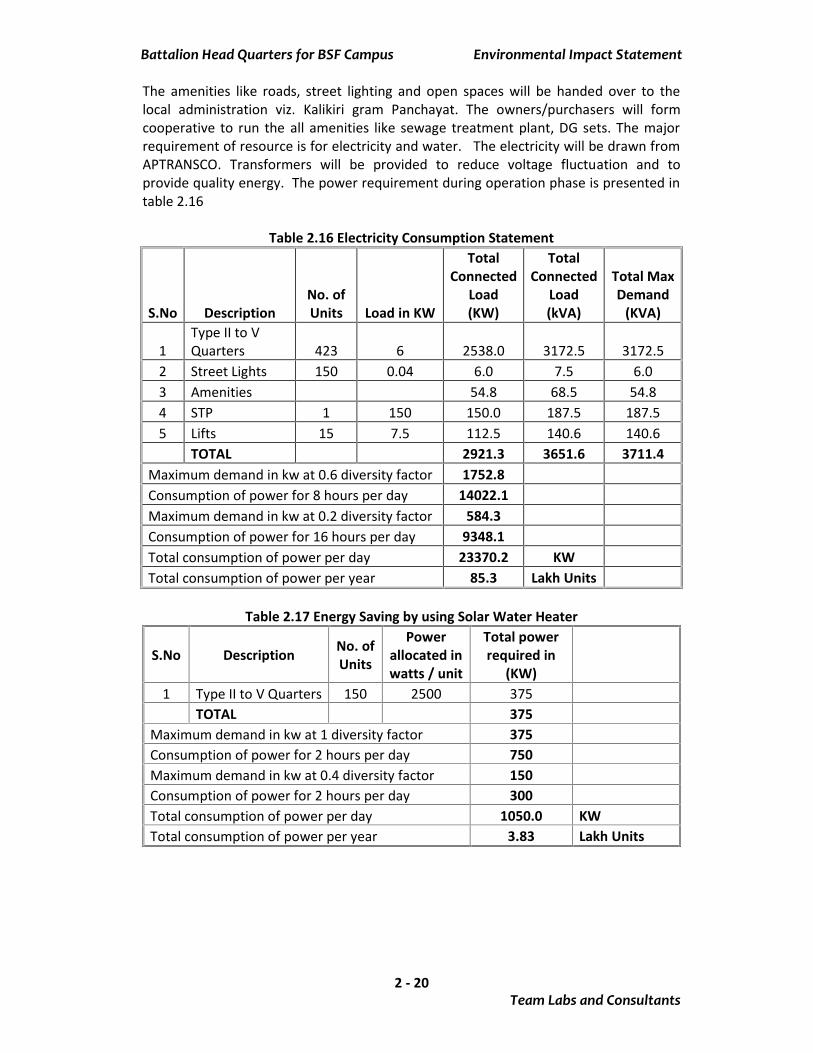
The amenities like roads, street lighting and open spaces will be handed over to thelocal administration viz. Kalikiri gram Panchayat. The owners/purchasers will formcooperative to run the all amenities like sewage treatment plant, DG sets. The majorrequirement of resource is for electricity and water. The electricity will be drawn fromAPTRANSCO. Transformers will be provided to reduce voltage fluctuation and toprovide quality energy. The power requirement during operation phase is presented intable 2.16
Table 2.16 Electricity Consumption Statement
S.No DescriptionNo. ofUnits Load in KW
TotalConnected
Load(KW)
TotalConnected
Load(kVA)
Total MaxDemand
(KVA)
1Type II to VQuarters 423 6 2538.0 3172.5 3172.5
2 Street Lights 150 0.04 6.0 7.5 6.03 Amenities 54.8 68.5 54.84 STP 1 150 150.0 187.5 187.55 Lifts 15 7.5 112.5 140.6 140.6
TOTAL 2921.3 3651.6 3711.4Maximum demand in kw at 0.6 diversity factor 1752.8Consumption of power for 8 hours per day 14022.1Maximum demand in kw at 0.2 diversity factor 584.3Consumption of power for 16 hours per day 9348.1Total consumption of power per day 23370.2 KWTotal consumption of power per year 85.3 Lakh Units
Table 2.17 Energy Saving by using Solar Water Heater
S.No Description No. ofUnits
Powerallocated inwatts / unit
Total powerrequired in
(KW)1 Type II to V Quarters 150 2500 375
TOTAL 375Maximum demand in kw at 1 diversity factor 375Consumption of power for 2 hours per day 750Maximum demand in kw at 0.4 diversity factor 150Consumption of power for 2 hours per day 300Total consumption of power per day 1050.0 KWTotal consumption of power per year 3.83 Lakh Units
Battalion Head Quarters for BSF Campus Environmental Impact Statement
Team Labs and Consultants2 - 21
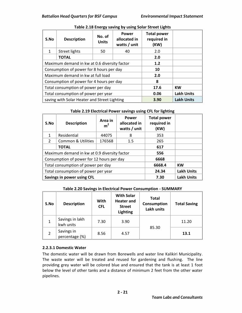
Table 2.18 Energy saving by using Solar Street Lights
S.No Description No. ofUnits
Powerallocated inwatts / unit
Total powerrequired in
(KW)1 Street lights 50 40 2.0
TOTAL 2.0Maximum demand in kw at 0.6 diversity factor 1.2Consumption of power for 8 hours per day 10Maximum demand in kw at full load 2.0Consumption of power for 4 hours per day 8Total consumption of power per day 17.6 KWTotal consumption of power per year 0.06 Lakh Unitssaving with Solar Heater and Street Lighting 3.90 Lakh Units
Table 2.19 Electrical Power savings using CFL for lighting
S.No Description Area inm2
Powerallocated inwatts / unit
Total powerrequired in
(KW)1 Residential 44075 8 3532 Common & Utilities 176568 1.5 265
TOTAL 617Maximum demand in kw at 0.9 diversity factor 556Consumption of power for 12 hours per day 6668Total consumption of power per day 6668.4 KWTotal consumption of power per year 24.34 Lakh UnitsSavings in power using CFL 7.30 Lakh Units
Table 2.20 Savings in Electrical Power Consumption - SUMMARY
S.No Description WithCFL
With SolarHeater and
StreetLighting
TotalConsumption
Lakh unitsTotal Saving
1 Savings in lakhkwh units
7.30 3.9085.30
11.20
2 Savings inpercentage (%)
8.56 4.57 13.1
2.2.3.1 Domestic WaterThe domestic water will be drawn from Borewells and water line Kalikiri Municipality.The waste water will be treated and reused for gardening and flushing. The lineproviding grey water will be colored blue and ensured that the tank is at least 1 footbelow the level of other tanks and a distance of minimum 2 feet from the other waterpipelines.
Battalion Head Quarters for BSF Campus Environmental Impact Statement
Team Labs and Consultants2 - 22
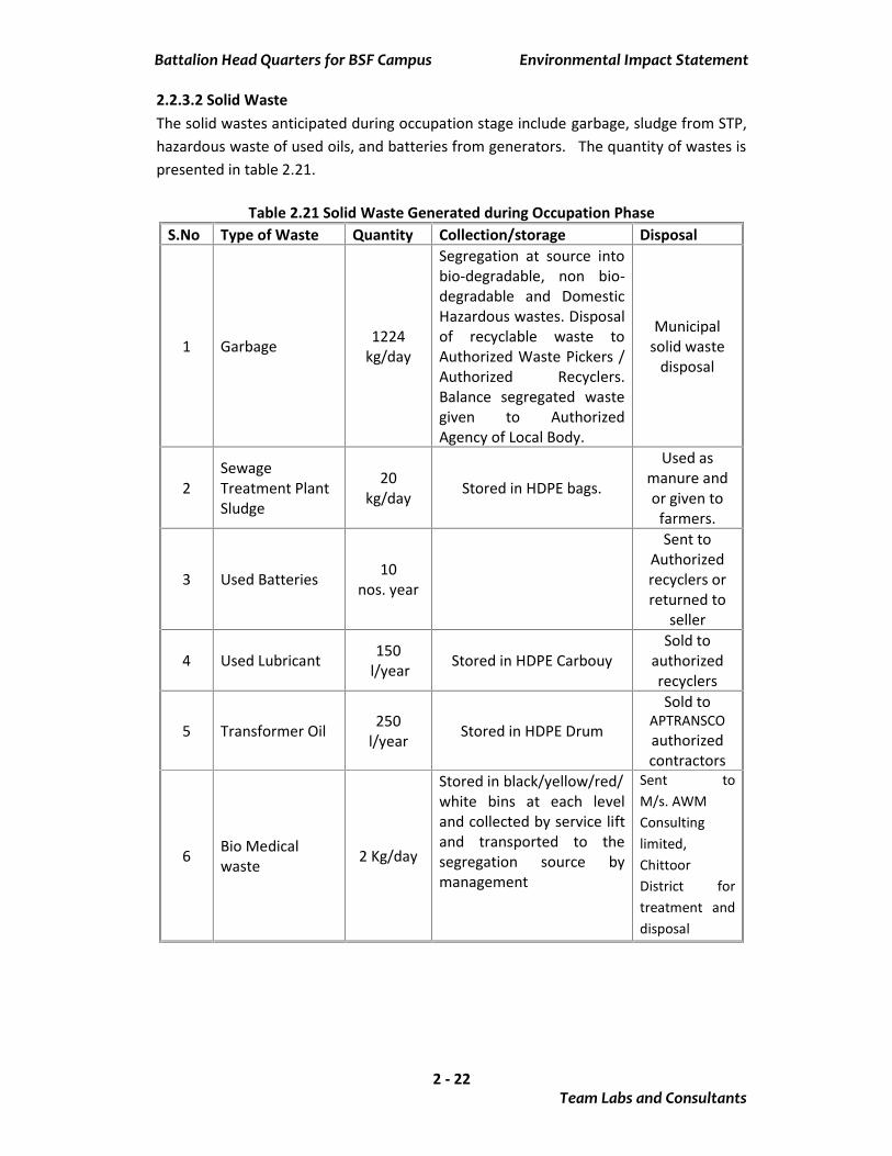
2.2.3.2 Solid WasteThe solid wastes anticipated during occupation stage include garbage, sludge from STP,hazardous waste of used oils, and batteries from generators. The quantity of wastes ispresented in table 2.21.
Table 2.21 Solid Waste Generated during Occupation PhaseS.No Type of Waste Quantity Collection/storage Disposal
1 Garbage 1224kg/day
Segregation at source intobio-degradable, non bio-degradable and DomesticHazardous wastes. Disposalof recyclable waste toAuthorized Waste Pickers /Authorized Recyclers.Balance segregated wastegiven to AuthorizedAgency of Local Body.
Municipalsolid waste
disposal
2SewageTreatment PlantSludge
20kg/day Stored in HDPE bags.
Used asmanure andor given to
farmers.
3 Used Batteries 10nos. year
Sent toAuthorizedrecyclers orreturned to
seller
4 Used Lubricant 150l/year Stored in HDPE Carbouy
Sold toauthorizedrecyclers
5 Transformer Oil 250l/year Stored in HDPE Drum
Sold toAPTRANSCOauthorizedcontractors
6 Bio Medicalwaste 2 Kg/day
Stored in black/yellow/red/white bins at each leveland collected by service liftand transported to thesegregation source bymanagement
Sent toM/s. AWMConsultinglimited,ChittoorDistrict fortreatment anddisposal

Battalion Head Quarters for BSF CampusCentral Public Works Department (CPWD)
Survey Nos. 83, 84, 86, 397, 183/A1, 184/1,Pathegada, Kalikiri Mandal, Chittoor District,
Andhra Pradesh
Studies and Documentation by:Team Labs and Consultants(An ISO Certified Organization)B-115 – 117 & 509, Annapurna Block,Aditya Enclave, Ameerpet,Hyderabad- 500 038Phone: 91-040-23748555/23748616Fax : 91-040-23748666e-mail: [email protected]