Embed Size (px)
Citation preview

GLOBAL STANDARD Page 1 of 87
CONCRETE POLES FOR DISTRIBUTION NETWORKS
GSS002 Rev. 04
21/09/2018
CONCRETE POLES FOR DISTRIBUTION NETWORKS
Countries I&N
Argentina C. Espinoza
Brazil R. Sales
Chile D. Sarkis
Colombia J. C. Gomez
Italy L. Giansante
Peru R. Sanchez
Romania V. Obrejan
Spain J. Gonzalez
This document is intellectual property of ENEL Global Infrastructure & Networks Srl; reproduction or distribution of its contents in any way or by any means whatsoever is subject to the prior approval of the above mentioned companies which will safeguard their rights under the civil and penal codes. This document is for Internal Use.
Revision Date List of modifications
00 30/03/2015 First emission
01 03/05/2016 Correction of Table 6,Table 18 and update of the Common List
02 10/07/2018 Local Section Latam general update
03 10/08/2018 Correction of Table 3a and Common list for Brazil
04 21/09/2018 Additional requirements for Enel Distribución Colombia
Elaborated by Verified by Approved by
Global I&N – O&M/NCS L. Foddai N. Cammalleri M. Mazzotti
GLOBAL STANDARD Page 2 of 87
CONCRETE POLES FOR DISTRIBUTION NETWORKS
GSS002 Rev. 04
21/09/2018
INDICE
1 SCOPE 4
2 DEFINITIONS 4
3 LIST OF COMPONENTS 5
4 REFERENCE LAWS AND STANDARDS 5
4.1 International standards ................................................................................................ 5
4.2 Local Standards ............................................................................................................ 6
4.3 List of replaced Local Standards ................................................................................. 6
5 SERVICE CONDITIONS 6
5.1 Environmental Conditions ........................................................................................... 6
6 CLASSIFICATION 6
7 DESIGN AND MANUFACTURE 10
7.1 Manufacturing materials .............................................................................................. 10
7.2 Dimensions ................................................................................................................... 10
7.3 Finished pole ................................................................................................................ 11
7.4 Holes ............................................................................................................................. 11
7.5 Tolerance ...................................................................................................................... 11
7.6 Embedment length ....................................................................................................... 11
7.7 Elasticity ........................................................................................................................ 11
7.7.1 Sag 11
7.7.2 Residual Sag 11
7.7.3 Cracks 11
7.8 Nominal Stress ............................................................................................................. 11
7.9 Safety factor .................................................................................................................. 11
7.10 Grounding or Earthing system ................................................................................ 11
7.11 Marking and designation of pole ............................................................................ 11
7.12 Safety line. ................................................................................................................ 11
7.13 Lifetime ..................................................................................................................... 11
8 TEST 11

GLOBAL STANDARD Page 3 of 87
CONCRETE POLES FOR DISTRIBUTION NETWORKS
GSS002 Rev. 04
21/09/2018
8.1 Qualification test .......................................................................................................... 11
8.2 Type test ........................................................................................................................ 12
8.2.1 Sampling plan (type) 12
8.2.2 List of type tests 12
8.3 Reception test ............................................................................................................... 12
8.3.1 Sampling plan (reception) 12
8.3.2 List of reception tests 12
8.4 Other tests .................................................................................................................... 12
9 CONFORMITY ASSESSMENT 12
9.1 Conditions of supplier .................................................................................................. 12
9.2 Acceptance and rejection ............................................................................................ 12
10 GUARANTEE 13
11 TECHNICAL INFORMATION FROM THE MANUFACTURER 13
11.1 General ..................................................................................................................... 13
11.2 Information for the proposed .................................................................................. 13
11.3 Design drawing ........................................................................................................ 13
A. LOCAL SECTION – LATAM: ENEL DISTRIBUIÇÃO RIO (BRAZIL), ENEL DISTRIBUIÇÃO CEARÁ (BRAZIL), ENEL DISTRIBUIÇÃO GOIÁS (BRASIL), ENEL DISTRIBUCIÓN CHILE (CHILE), ENEL DISTRIBUCIÓN COLOMBIA (COLOMBIA), ENEL DISTRIBUCIÓN PERÚ (PERÙ), EDESUR (ARGENTINA). 14
B. LOCAL SECTION – ENDESA DISTRIBUCIÓN ELÉCTRICA (SPAIN) 53
C. LOCAL SECTION – E-DISTRIBUZIONE (ITALY), ENEL DISTRIBUTIE: BANAT, DOBROGEA, MUNTENIA (ROMANIA). 66
COMMON LIST OF MAIN REQUIREMENTS 75
GLOBAL STANDARD Page 4 of 87
CONCRETE POLES FOR DISTRIBUTION NETWORKS
GSS002 Rev. 04
21/09/2018
1 SCOPE
The standard specifications establishes characteristics about concrete poles that will be used on electric distribution overhead lines up to 33 kV in the Enel Group Distribution Companies, listed below:
Enel Distribuição Rio (EDR) Brasil
Enel Distribuição Ceará (EDC) Brasil
Enel Distribuição Goiás (EDG) Brasil
Enel Distribución Chile (CH) Chile
Enel Distribución Colombia (CD) Colombia
Enel Distribución Perú (EN) Perú
Edesur (ES) Argentina
Endesa Distribución Eléctrica (EE) Spain
Enel Distributie Banat (ER) Romania
Enel Distributie Dobrogea (ER) Romania
Enel Distributie Muntenia (ER) Romania
E-Distribuzione (ED) Italy
This document is composed of one Common Main Section, and three Local Sections.
Additional requirements are added to the common main section by the corresponding clause or sub-clause numbers that is found in the Local sections, which provide additional information about poles of each country in question.
2 DEFINITIONS
Pole
Slender vertical structure rigidly fixed at the base.
Normal Pole
Pole that resists nominal stress “En” at a distance “d” below from the top.
Butt
Lower end of pole.
Top
Upper end of pole.
Nominal Distance (L)
Distance from butt up to top of the pole.
Concrete
Cement mixture, aggregates (sand, gravel) and water.
Metal Reinforcement Steel – Rebar
Steel bar or mesh of steel wires used as a stress device in reinforced concrete, to strengthen and hold the concrete in stress.
Embedment Length or Embedment distance (he)
Segment length of the pole buried firmly in the earth or concrete base.
Main Direction or Cross Direction
Perpendicular direction to the axis pole at which point maximum stress resistance is present.
LATAM
EUROPE

GLOBAL STANDARD Page 5 of 87
CONCRETE POLES FOR DISTRIBUTION NETWORKS
GSS002 Rev. 04
21/09/2018
Secondary Direction or Longitudinal
Normal direction to the axis pole and perpendicular to the main direction.
Nominal Stress or Admissible Load (En)
It is the stress by which the pole is designated and represents the free stress in the main direction at a distance "d" below from the top of the pole.
Tensile Test (T1)
It is the term used in ENEL for the maximum stress in the primary direction that causes breaking, required by the pole.
Secondary Stress (Es)
The stress level that a pole can resist in the secondary direction (perpendicular at the primary direction) applied at a distance “d” below from the top.
Breaking Strength or Tensile Strength (Er)
It is one that, apply according to normal poles and reinforced poles, perpendicular to the axis pole and on the plane of bending, causes a breaking stress.
Torsional Stress (Et)
Horizontal stress available at the top of the pole, located at d = 0.25m below the top and at a distance dh = 1.5m from center thereof which tends to make it rotate around its axis.
Safety factor (CS)
Is the relationship between the breaking load per the permissible specified load.
Sag
Measuring displacement of a point located in the plane of application of the stresses, caused by the action of them.
Crack
Fissure on the pole surface in which separating edges can be distinguished with the naked eye.
Capillary cracks
Fissure on the pole surface in which cannot see the edges with the naked eye.
Application Plane of Real Stresses
Transverse plane located at a distance “d” below the top.
Application Plane of Virtual Stresses
Transverse plane located at a distance “dv” above the top.
Conicity
Is the relationship between the differences of the diameters of the bases divided by the height of the pole.
3 LIST OF COMPONENTS
The list of components with the main requirements, which is an integral part of the document, is reported in: "Pole Project, Common List" appendix attached.
4 REFERENCE LAWS AND STANDARDS
Here below is reported the list of reference laws and standards mentioned in this document.
4.1 International standards
See Local Section.

GLOBAL STANDARD Page 6 of 87
CONCRETE POLES FOR DISTRIBUTION NETWORKS
GSS002 Rev. 04
21/09/2018
4.2 Local Standards
See Local Section.
4.3 List of replaced Local Standards
See Local Sections.
5 SERVICE CONDITIONS
5.1 Environmental Conditions
In general, poles for distribution networks should be supplied to operate satisfactorily in outdoor environments under the conditions presented in Table 1.
Table 1: Environmental characteristics
Characteristics
EN
EL
DIS
TR
IBU
IÇÃ
O
RIO
/ G
OIÁ
S
EN
EL
DIS
TR
IBU
IÇÃ
O
CE
AR
Á
EN
EL
DIS
TR
IBU
CIÓ
N
CO
LO
MB
IA
EN
EL
DIS
TR
IBU
CIÓ
N
CH
ILE
EN
EL
DIS
TR
IBU
CIÓ
N
PE
RÚ
ED
ES
UR
EN
EL
Dis
trib
uti
e
E-D
istr
ibu
zio
ne
EN
DE
SA
Altitude (m) < 1.000 < 1.000 2.700 < 1.000 < 1.000 < 1.000 - - -
Relative moisture (IEC – 60721-2-1)
100% 95% 90% 100% 100% 100% - - -
Pollution level (IEC 60815)
High (III)
Very High (IV)
Medium (II)
Medium (II)
Very High (IV)
Medium (II)
Medium (II)
Medium (II)
Medium (II)
Seismic activity No No Yes(1) Yes(1) Yes(1) No Yes(1) Yes(1) No
(1) For seismic requirements see Local Sections.
6 CLASSIFICATION
The classifications of concrete poles are shown in Table 2.
Table 2: Types of concrete poles

GLOBAL STANDARD Page 7 of 87
CONCRETE POLES FOR DISTRIBUTION NETWORKS
GSS002 Rev. 04
21/09/2018
Type Model Description
HV Reinforced
vibrated concrete
Reinforced vibrated concrete pole whose geometric shape is that of a truncated pyramid of rectangular outside beam.
HC
Centrifuged reinforced concrete
Centrifuged reinforced concrete pole whose geometric shape is that of a truncated circular ring section beam.
HCV Reinforced
vibrated concrete
Reinforced vibrated concrete pole whose geometric shape is that of a truncated circular ring section beam
The typical configuration of the pole type HV is shown in Figure 1, the main parts are: Top section or
Cogolla and butt section, nominal stress and secondary stress, total length, solid section length and
embedment length.
Reinforced vibrated concrete has the geometric form of a frustum beam of rectangular solid outer
section in the first few meters from the top and with shaped "I" section reinforced with ribs on the
other length.

GLOBAL STANDARD Page 8 of 87
CONCRETE POLES FOR DISTRIBUTION NETWORKS
GSS002 Rev. 04
21/09/2018
Figure 1: Scheme concrete pole type HV
Concrete poles type HV is used by ENDESA, ENEL DISTRIBUIÇÃO RIO, ENEL DISTRIBUIÇÃO CEARÁ, ENEL DISTRIBUIÇÃO GOIÁS and ENEL DISTRIBUCIÓN CHILE are defined by the characteristic features: Nominal length, Nominal stress and secondary stress. See details in the corresponding Local Section.
The typical configuration of the pole type HC is shown in Figure 2, whose main part are: Top diameter and butt diameter, nominal stress, total length and embedment length, see characteristic definitions in
Em
bedm
ent
Nominal stress (En)
Secondary stress
(Es)
(d)
(dh)
Torsional stress
(Et)
Top
Butt

GLOBAL STANDARD Page 9 of 87
CONCRETE POLES FOR DISTRIBUTION NETWORKS
GSS002 Rev. 04
21/09/2018
paragraph 2. The pole has the geometric shape of a truncated circular cross-section beam, hollow along nominal length.
Figure 2: Scheme concrete pole type HC
Concrete poles type HC are used by ENEL, ENEL DISTRIBUCIÓN COLOMBIA, ENEL DISTRIBUCIÓN PERU, and EDESUR are defined by the following features: Nominal length, Nominal stress.
Concrete poles type HCV are used in ENEL DISTRIBUIÇÃO GOIÁS and ENEL DISTRIBUCIÓN COLOMBIA. The typical configuration of the pole type HCV is shown in Figure 3, whose main part are: Top diameter and butt diameter, nominal stress, total length and embedment length, see characteristic definitions in paragraph 2.
The pole has the geometric shape of a truncated circular cross-section beam, hollow along nominal
length and closed on the top.

GLOBAL STANDARD Page 10 of 87
CONCRETE POLES FOR DISTRIBUTION NETWORKS
GSS002 Rev. 04
21/09/2018
Figure 3: Scheme concrete pole type HCV
7 DESIGN AND MANUFACTURE
7.1 Manufacturing materials
The materials used for manufacturing poles, shall be tested in accordance with corresponding Local Standards. See Local section.
7.2 Dimensions
See Local Section.

GLOBAL STANDARD Page 11 of 87
CONCRETE POLES FOR DISTRIBUTION NETWORKS
GSS002 Rev. 04
21/09/2018
7.3 Finished pole
The poles shall provide sufficiently smooth outer surfaces, no sharp edges, no cracks or fractures (except small capillary cracks, not longitudinally oriented, inherent in the material) without visible rebar.
7.4 Holes
Holes for fittings and cables shall be cylindrical and shall comply the following requirements:
a) The holes for fixing fittings should have an axis perpendicular to the pole axis and be centered on opposite sides.
b) The holes shall not provide obstructions and shall not expose any part of the rebar.
c) The location of the holes and their tolerances are specified in the Local Section.
7.5 Tolerance
See Local Section.
7.6 Embedment length
See Local Section.
7.7 Elasticity
See Local Section.
7.7.1 Sag
See Local Section.
7.7.2 Residual Sag
See Local Section.
7.7.3 Cracks
See Local Section.
7.8 Nominal Stress
For further details see 7.2 Local Section.
7.9 Safety factor
See local Section.
7.10 Grounding or Earthing system
See Local Section.
7.11 Marking and designation of pole
See Local Section.
7.12 Safety line.
See Local Section.
7.13 Lifetime
See Local Section.
8 TEST
8.1 Qualification test
Prior to conducting the tests the manufacturer shall provide the information requested in paragraph 11.
GLOBAL STANDARD Page 12 of 87
CONCRETE POLES FOR DISTRIBUTION NETWORKS
GSS002 Rev. 04
21/09/2018
8.2 Type test
Tests carried out before marketing a type of pole, in order to prove that their service features correspond to the intended applications.
8.2.1 Sampling plan (type)
Shall be carried out in a limited sample for each type of pole to be utilized.
8.2.2 List of type tests
For further details of the procedure and requirements see Local Section.
8.3 Reception test
Tests performed by the provider during delivery.
8.3.1 Sampling plan (reception)
See Local Section.
8.3.2 List of reception tests
For further details of the procedure and requirements see Local Section.
8.4 Other tests
See Local Section.
9 CONFORMITY ASSESSMENT
9.1 Conditions of supplier
The manufacturer shall provide personnel and equipment necessary to carry out type tests and receiving described herein. Or in failing to hire the service, to a laboratory previously accepted by the customer and assume the cost. The product must comply with the requirements of GSCG002 regarding the Technical Conformity Assessment.
The equipment should be properly calibrated by a laboratory certified or approved by the client. The manufacturer shall possess daily calibration certificates (to turn over) at the time of inspection.
9.2 Acceptance and rejection
All poles rejected during receiving tests that are within accepted lots, will be replaced by the manufacturer with new units in perfect condition without charge to the Customer.
Acceptance of a lot by the customer does not relieve the manufacturer of liability to provide poles with the requirements of this specification or invalidate claims that the customer makes about the quality of the material used and the manufacturing of the pole.

GLOBAL STANDARD Page 13 of 87
CONCRETE POLES FOR DISTRIBUTION NETWORKS
GSS002 Rev. 04
21/09/2018
10 GUARANTEE
The manufacturer will guarantee that the poles supplied meet all requirements of this Specification. The poles will be warranted against manufacturing defects for a period of 5 years in addition to meeting the requirements listed in this specification.
11 TECHNICAL INFORMATION FROM THE MANUFACTURER
11.1 General
All documents related to the proposal, such as drawings, technical descriptions, specifications, shall use the measurement units of the metric system.
11.2 Information for the proposed
Each bidder shall submit with its bid the information requested in this specification and any other information necessary to enable the distributor to select the poles to acquire.
11.3 Design drawing
See Local Section.

GLOBAL STANDARD Page 14 of 87
CONCRETE POLES FOR DISTRIBUTION NETWORKS
GSS002 Rev. 04
21/09/2018
A. LOCAL SECTION – LATAM: ENEL DISTRIBUIÇÃO RIO (BRAZIL), ENEL DISTRIBUIÇÃO CEARÁ (BRAZIL), ENEL DISTRIBUIÇÃO GOIÁS (BRASIL), ENEL DISTRIBUCIÓN CHILE (CHILE), ENEL DISTRIBUCIÓN COLOMBIA (COLOMBIA), ENEL DISTRIBUCIÓN PERÚ (PERÙ), EDESUR (ARGENTINA).

GLOBAL STANDARD Page 15 of 87
CONCRETE POLES FOR DISTRIBUTION NETWORKS
GSS002 Rev. 04
21/09/2018
ITEM TITLE DESCRIPTION
4.2 Local standards
ENEL DISTRIBUIÇÃO RIO / ENEL DISTRIBUIÇÃO CEARÁ / ENEL
DISTRIBUIÇÃO GOIÁS
NBR 5732:1991 : Cimento Portland comum.
NBR 5733:1991 : Cimento Portland de alta resistência
inicial
NBR 5737:1991 : Cimento Portland resistentes a sulfatos
NBR 5738:1994 : Concreto - Procedimento para
moldagem e cura de corpos-de-prova.
NBR 5739:1991 : Concreto - Ensaios de compressão de
corpos-de-prova cilíndricos
NBR 6118:2007 : Projeto de estruturas de concreto -
Procedimento.
NBR 6210 : Corrosão atmosférica – Materiais metálicos – Preparo,
limpeza e determinação da taxa de corrosão de corpos-de-
prova em ensaios de corrosão.
NBR 7211 : Agregado para Concreto – Especificação.
NBR 7480:2007 : Aço destinado a armaduras para
estruturas de concreto armado - Especificação
NBR 7482:2008 : Fios de aço para estruturas de concreto
protendido - Especificação
NBR 7483:2008 : Cordoalhas de aço para estruturas de
concreto protendido – Especificação
NBR 8451-1 : Postes de concreto armado e protendido para redes de
distribuição e de transmissão de energia elétrica – Parte 1:
Requisitos;
NBR 8451-2 : Postes de concreto armado e protendido para redes de
distribuição e de transmissão de energia elétrica – Parte 2:
Padronização de postes para redes de distribuição de
energia elétrica;
NBR 8451-3 : Postes de concreto armado e protendido para redes de
distribuição e de transmissão de energia elétrica – Parte 3:
Ensaios mecânicos, cobrimento da armadura e inspeção
geral.

GLOBAL STANDARD Page 16 of 87
CONCRETE POLES FOR DISTRIBUTION NETWORKS
GSS002 Rev. 04
21/09/2018
NBR 8451-4 : Postes de concreto armado e protendido para redes de
distribuição e de transmissão de energia elétrica – Parte 4:
Determinação da absorção de água.
NBR 8451-5 : Postes de concreto armado e protendido para redes de
distribuição e de transmissão de energia elétrica – Parte 5:
Postes de concreto para entrada de serviço até 1kV.
NBR 8451-6 : Postes de concreto armado e protendido para redes de
distribuição e de transmissão de energia elétrica – Parte 6:
Postes de concreto armado e protendido para linhas de
transmissão e subestações de energia elétrica – Requisitos,
padronização e ensaios
NBR 12654:2000 : Controle tecnológico de materiais componentes do
concreto - Procedimento
NBR 12655:2006 : Concreto de cimento Portland - Preparo, controle e
recebimento – Procedimento
NBR 14643 : Corrosão Atmosférica – Classificação da corrosividade de
atmosferas.
NBR 7680 : Extração, preparo e ensaios de testemunhos de concreto.
NBR 11768 : Aditivos químicos para concreto de cimento Portland –
Requisitos.
ENEL DISTRIBUCION CHILE NCh148:1968 : Cemento - Terminología, clasificación y especificaciones
generales.
NCh163:1979 : Áridos para morteros y hormigones - Requisitos generales
NCh204:2006 : Acero - Barras laminadas en caliente para hormigón
armado hormigón
NCh205:1968 : Acero - Barras reviradas para hormigón armado
NCh170:1985 : Hormigón - Requisitos generales
NCh1498:1982 : Hormigón – Agua de amasado – Requisitos
NSEG 5.E.n.71 : Reglamento de instalaciones eléctricas de corrientes
fuertes.
DMAD-0182 / SDO-8156: Poste de Hormigón Armado de 8,7m DMAD-0180 / SDO-8158: Poste de Hormigón Armado de 11,5m DMAD-0184 / CHI-25930: Poste de Hormigón Armado de 13,5m DMAD-0183 / SDO-11411: Poste de Hormigón Armado de 15,0m PDAR-3011: Procedimiento de ensayos de recepción a postes en fábrica
CMD-14161: Cancha para ensayes

GLOBAL STANDARD Page 17 of 87
CONCRETE POLES FOR DISTRIBUTION NETWORKS
GSS002 Rev. 04
21/09/2018
ENEL DISTRIBUCIÓN COLOMBIA NTC 30 : Cemento portland. Clasificación y nomenclatura.
NTC 121 : Ingeniería civil y arquitectura. cemento portland.
Especificaciones físicas y mecánicas.
NTC 321 : Ingeniería civil y arquitectura. Cemento portland.
Especificaciones
NTC 174 : Concretos. Especificaciones de los agregados para
concreto.
NTC 2 : Ensayo de tracción para productos de acero
NTC 116 : Alambre duro de acero para refuerzo de concreto.
NTC 159 : Alambres de acero sin recubrimiento liberados de esfuerzo
para concreto pretensado.
NTC 161 : Barras lisas de acero al carbono para hormigón armado.
NTC 248 : Barras y rollos corrugados de acero al carbono para
hormigón armado
NTC 673 : Ensayo de resistencia a la compresión, de cilindros
normales de hormigón.
NTC 1299 : Aditivos químicos para el hormigón.
NTC 2010 : Torones de acero de siete alambres sin recubrimiento para
concreto pretensado.
NTC 1329 : Prefabricados en concreto. postes de concreto para líneas
de energía eléctrica y telecomunicaciones.
RETIE : Reglamento técnico de instalaciones eléctricas.
RETILAP : Reglamento Tecnico de Illuminacion y Alumbrado Publico

GLOBAL STANDARD Page 18 of 87
CONCRETE POLES FOR DISTRIBUTION NETWORKS
GSS002 Rev. 04
21/09/2018
ENEL DISTRIBUCIÓN PERU
NTP 334.009 : CEMENTOS. Cemento Portland. Requisitos. 5a. Ed.
NTP 334.090 : CEMENTOS. Cementos Portland adicionados. Requisitos. 5a. ed.
NTP 334.082 : CEMENTOS. Cemento Portland. Especificación de la Performance. 3a. ed.
NTP 400.037 : AGREGADOS. Agregados para concreto. Requisitos. 4ª Edición
NTP 400.012 : AGREGADOS. Análisis granulométrico del agregado fino, grueso y global
NTP 339.088: CONCRETO. Agua de mezcla utilizada en la producción de concreto de cemento Portland. Requisitos
NTP 341.031 : HORMIGÓN (CONCRETO). Barras de acero al carbono con resaltes y lisas para hormigón (concreto) armado. Especificaciones
NTP 341.032 : Tochos, palanquillas, planchones y llantones de acero al carbono para laminar productos de uso estructural. 1ª Edición
NTP 339.034 : HORMIGÓN (Concreto). Método de ensayo normalizado para la determinación de la resistencia a la compresión del concreto, en muestras cilíndricas. 3a. ed.
NTP 339.059 : CONCRETO. Método de ensayo normalizado para la obtención y ensayo de corazones diamantinos y vigas seccionadas de concreto. 3a ed.
NTP 339.088 : HORMIGÓN (CONCRETO). Agua de mezcla utilizada en la producción de concreto de cemento Portland. Requisitos
NTP 339.027 : HORMIGON (CONCRETO). Postes de hormigón (concreto) armado para líneas aéreas. 2a. ed.
NTP 339.187 : HORMIGÓN (CONCRETO). Método de ensayo normalizado para determinar la densidad, absorción y porcentaje de vacíos en el hormigón (concreto) endurecido

GLOBAL STANDARD Page 19 of 87
CONCRETE POLES FOR DISTRIBUTION NETWORKS
GSS002 Rev. 04
21/09/2018
EDESUR IRAM 50000 : Cemento para uso general. Composición,
características, evaluación de la conformidad y condiciones
de recepción.
IRAM 50001 : Cemento. Cementos con propiedades especiales.
IRAM 1512 : Agregado fino para hormigón de cemento. Requisitos.
IRAM 1531 : Agregado grueso para hormigón de cemento. Requisitos
IRAM 1627 : Agregados. Granulometría de los agregados para
hormigones.
IRAM 1634 : Hormigón de cemento. Método de ensayo de compresión.
IRAM 1585 : Elementos estructurales de hormigón. Sistema
constructivo de la toma de tierra en elementos de hormigón
armado o pretensado para soporte de instalaciones aéreas.
IRAM 1601 : Agua para morteros y hormigones de cemento.
IRAM 1605 : Postes de hormigón pretensado, de sección anular y
forma troncocónica, para soporte de instalaciones aéreas.
IRAM 1663 : Hormigón de cemento. Aditivos químicos.
IRAM 15 : Inspección por atributos. Planes de muestra única, doble o
múltiple, con rechazo.
IRAM 18 : Muestreo al azar.
IRAM-IAS U500-03 : Cordones de siete alambres de acero para
estructuras de hormigón pretensado.
IRAM-IAS U500-07 : Cordones de dos o tres alambres de acero para
estructuras de hormigón pretensado.
IRAM-IAS U500-26 : Alambres de acero para armadura en estructuras
de hormigón.
IRAM-IAS U500-207 : Barras de acero conformadas de dureza natural
soldables, para armadura en estructuras de hormigón.
IRAM-IAS U500-245 : Alambres de acero conformado para estructuras de
hormigón pretensado.
IRAM-IAS U500-502 : Barras de acero laminadas en caliente, lisas y de
sección circular para armadura en estructuras de hormigón.
IRAM-IAS U500-517 : Alambres para hormigón pretensado.
IRAM-IAS U500-528: Barras de acero conformadas de dureza natural, para
armadura en estructuras de hormigón.
IRAM 1666-1 : Hormigón de cemento Portland. Hormigón elaborado.
Requisitos, inspección y recepción y métodos de ensayo.
AEA95201 - Edición 2003: Asociación Electrotécnica Argentina:
Reglamentación de líneas aéreas exteriores de baja tensión.
AEA95301 - Edición 2007: Asociación Electrotécnica Argentina:
Reglamentación de líneas aéreas exteriores de media y alta
tensión.
CIRSOC 201 : Proyecto, cálculo y ejecución de estructuras de hormigón
armado y pretensado. Edición julio1982. Actualización 1984.
4.3 List of replaced Local Standards
E-MT-024 : POSTES DE CONCRETO PARA REDES DE DISTRIBUCION
HASTA 23 KV

GLOBAL STANDARD Page 20 of 87
CONCRETE POLES FOR DISTRIBUTION NETWORKS
GSS002 Rev. 04
21/09/2018
5.1 Environmental Conditions
ENEL DISTRIBUCIÓN PERU / ENEL DISTRIBUCION CHILE Seismic requirements: for Enel Distribución Peru the technical specification E-SE-010 applies. For Enel Distribución Chile the technical specification ETG-1020 applies.
6 CLASSIFICATION
Pre-stressed pole:
ENEL DISTRIBUCIÓN COLOMBIA
It is the pole which steel reinforcement bar has been pre-stressed. This initial pre-stressed steel should not be transferred to the concrete until it no longer has strength of 245 kg/cm2 and before tensioning losses occur.
The minimum resistance to compression of concrete shall be 245kg/cm² (3 500 psi) for conventional poles and 350 kg/cm² (5 000 psi) for pre-stressed poles. This resistance shall be verified through laboratory tests on sections taken from different lots according to standard ICONTEC 673.
The minimum strength of steel shall be 4218 kg / cm² (60000psi) and shall not exceed 0.94 at the time of initial pre-tensioning. Steel spirals or rings shall be made of smooth or corrugated rods of 6.4 mm minimum diameter.
EDESUR At the time of applying the force of pre-compression, compression stresses in the concrete should not exceed 50% of the characteristic strength of concrete at the age.
7.1 Manufacturing materials
ENEL
DISTRIBUIÇ
ÃO
RIO/ENEL
DISTRIBUIÇ
ÃO CEARÁ
ENEL
DISTRIBUC
IÓN
COLOMBIA
ENEL
DISTRIBUC
IÓN CHILE
ENEL
DISTRIBUCI
ÓN PERÚ
EDESUR
Cement NBR 5732
NBR 5733
NTC 030 NTC 121 NTC 321
NCh148
Of68
NTP 334.009 NTP 334.090 NTP 334.082
IRAM 50000 IRAM 50001
Aggregate
s (Gravel) NBR 7211 NTC 174
NCh163
Of54
NTP 400.037 NTP 400.012
IRAM 1512 IRAM 1531 IRAM 1627
Water NBR 8451-4 -
NCh1498
Of82 NTP 339.088
IRAM 1601
Steel
NBR 7480
NBR 7482
NBR 7483
NTC 2
NTC 116 NTC 159 NTC 161 NTC 2010 NTC 248
NCh204
Of77
NCh205
Of69
NTP 341.031 NTP 341.032
IRAM-IAS
U500-003
IRAM-IAS
U500-007
IRAM-IAS
U500-026
IRAM-IAS
U500-207
IRAM-IAS
U500-245
IRAM-IAS
U500-502
IRAM-IAS
U500-517
IRAM-IAS
U500-528
Concrete
NBR 5739
NBR 5738
NBR 12654
NBR 12655
NTC 673 NTC 1299
NCh170 of
85
NTP 339.034 NTP 339.059 NTP 339.088 NTP 339.027 NTP 339.187
IRAM 1666-1

GLOBAL STANDARD Page 21 of 87
CONCRETE POLES FOR DISTRIBUTION NETWORKS
GSS002 Rev. 04
21/09/2018
7.2 Dimensions
ENEL DISTRIBUIÇÃO RIO / ENEL DISTRIBUIÇÃO CEARÁ/ ENEL DISTRIBUIÇÃO GOIÁS :
Table 3a shows the different poles with their main nominal dimensions according to
the length and nominal stress. These poles are the HV type.
Length
L
(m)
Nominal
stress "En"
(daN)
Safety
factor
Top
measures
mm x mm
(± 5 mm)
Butt
measures
mm x mm
(± 5 mm)
L2
(mm)
± 20
L3
(mm)
± 20
L4
(mm)
+20
- 5
Distribution
Company
9 150 2.0 100 x 120 190 x 264 1150 75 1525 EDC
9 200 2.0 100 x 120 190 x 264 1000 75 3025 EDR
9 300 2.0 110 x 140 290 x 392 1150 75 1525 EDC
9 400 2.0 110 x 140 290 x 392 1000 75 3025 EDR
9 600 2.0 110 x 140 290 x 392 1000 75 3025 EDC/EDR
10 300 2.0 110 X 140 310 X 420 1100 975 3025 EDG
10 600 2.0 110 X 140 310 X 420 1100 975 3025 EDG
10.5 150 2.0 100 x 120 205 x 288 1350 1475 3025 EDC
10.5 300 2.0 110 x 140 320 x 434 1350 1475 3025 EDC
10.5 600 2.0 110 x 140 320 x 434 1350 1475 3025 EDC
10.5 1000 2.0 200 x 266 350 x 476 1350 1475 3025 EDC
11 200 2.0 100 x 120 210 x 296 1200 1875 4525 EDR
11 300 2.0 110 X 140 330 X 448 1200 1875 4525 EDG
11 400 2.0 110 x 140 330 x 448 1200 1875 4525 EDR
11 600 2.0 110 x 140 330 x 448 1200 1875 4525 EDR
11 1000 2.0 140 x 182 360 x 490 1200 1875 4525 EDR
11 1500 2.0 170 x 224 390 x 532 1200 1875 4525 EDR
12 300 2.0 110 x 140 350 x 476 1450 2775 4525 EDC/EDG
12 400 2.0 110 x 140 350 x 476 1300 2775 4525 EDR
12 600 2.0 110 x 140 350 x 476 1300 2775 4525 EDC/EDR

GLOBAL STANDARD Page 22 of 87
CONCRETE POLES FOR DISTRIBUTION NETWORKS
GSS002 Rev. 04
21/09/2018
12 1000 2.0 200 x 266 380 x 518 1300 2775 4525 EDC
12 1000 2.0 140 X 182 380 X 518 1300 2775 4525 EDR
12 2000 2.0 200 X 266 440 X 602 1300 2775 4525 EDR
13 600 2.0 110 X 140 370 X 504 1400 2775 4525 EDR
13 1000 2.0 140 X 182 400 X 546 1400 2775 4525 EDR
13 2000 2.0 200 X 266 460 X 630 1400 2775 4525 EDR
Table 3a: Nominal dimensions of the pole HV
The geometrical general configuration of the pole type HV is shown in paragraph 11.3
of this appendix, the dimensions of the main sections are detailed.
Table 3b shows the different poles with their main nominal dimensions according to the length and nominal stress. These poles are the HCV type.
Table 3b: Nominal dimensions of the pole HCV
1) (A) - Conicity 20 mm / m;
(B) - Conicity 15 mm / m.
2) The masses are approximate for conicity 20 mm / m and have no normative sense, and should not be required to observe them, including inspection.
3) Minimum values for the distance from the application plane Cn at the top of the pole equal to 100 mm.
4) The MA column values were obtained experimentally.
(A) (B)
C-17 300 450 149 820 170 350 305
C-19 600 900 298 1.000 190 370 325
10 C-23 1.000 900 592 1.350 230 430 380 975 1100 1600
C-19 600 900 322 1.260 190 410 355
C-23 1.000 900 602 1.600 230 450 395
C-29 1.500(Note 5)
900952 2.100 290 510 455
C-19 600 331 1.440 190 430 370
C-23 1.000 611 1.770 230 470 410
C-29 1.500 960 2.450 290 530 470
C-33 2.000 1311 3.000 330 570 510
C-17 300(Note 5)
450165 1.280 170 430 365
C-19 600 330 1.680 190 450 385
C-23 1.000 610 1.920 230 490 425
C-29 1.500 968 2.700 290 550 485
C-33 2.000 1310 3.500 330 590 525
14 C-19 600(Note 5)
900345 1.900 190 470 400 2775 1500 2000
13 2775 1400 1900
11 1875 1200 1700
LENGHT
L ± 0,05
(m)
12 2775 1300 1800
TYPE
DIMENSIONS (mm)
B ± 5
9 75 1000 1500
A ± 5F ± 20
(6)
J ± 20
(6)e ± 15
(Note 5)
900
900
(Note 5)
NOMINAL
STRESS
Cn
(daN)
NOMINAL
FLOUR
MOMENT
APPLIED ON
THE
APPLICATION
ADICIONAL
STRENGHT ON
THE
APPLICATION
PLAN OF Cn
(FA) (5) (daN)
MASS
(2)
(kg)

GLOBAL STANDARD Page 23 of 87
CONCRETE POLES FOR DISTRIBUTION NETWORKS
GSS002 Rev. 04
21/09/2018
5) The values of FA were calculated by the expression FA = (0,7 ME - MA) / h, where ME is the moment of settling (ME = Cn. Hu).
6) The F and J dimensions refer to the holes for the input and output of the grounding cable, and a built-in duct system can be used.
The geometrical general configuration of the pole type HCV is shown in paragraph 11.3 of this appendix, the dimensions of the main sections are detailed.
ENEL DISTRIBUCION CHILE
Table 4 shows the different poles with their main nominal dimensions according to the
length and nominal stress. These poles are the normal type.
Table 4: Nominal dimensions of the pole HV
Length L
(m)
Nominal stress "En"
(daN)
Secondary stress "Es"
(daN)
Safety factor
Top measures mm x mm (± 5 mm)
Butt measures mm x mm (± 5 mm)
8,7 225 60 2 120 x 120 220 x 350
11,5 267 125 2 150 x 150 250 x 430
13,5 660 340 2 165 x 180 300 x 450
15,0 660 240 2 150 x 150 300 x 450
The geometrical general configuration of the pole type HV is shown in paragraph 11.3
of this appendix, the dimensions of the main sections are detailed.
ENEL DISTRIBUCIÓN PERU
Table 5 shows the different poles with their main nominal dimensions according to the
length and nominal stress. These poles are the normal type.
The base of the post will be protected with a concrete sealer approved by ENEL, which will be applied from the embedment level (reference): 0.7m above and 0.5m below.
In paragraph 11.3 of this appendix, the dimensions of the main sections are detailed.
Table 5 : Conical frustum Poles ENEL DISTRIBUCIÓN PERÚ
Length L
(m)
Nominal stress "En"
(daN)
Safety factor
Top
ce
(mm)
Butt
ce
(mm)
B
(mm)
7 200
2.00
150 255 0.40
8 200 150 270 0.50
9 200 150 285 0.60

GLOBAL STANDARD Page 24 of 87
CONCRETE POLES FOR DISTRIBUTION NETWORKS
GSS002 Rev. 04
21/09/2018
11 200 150 315 0.80
11 400
2.50
180 345 0.80
13 400 180 375 1.00
15 400 210 435 1.20
ENEL DISTRIBUCIÓN COLOMBIA
Table 6 shows the different poles with their main nominal dimensions according to the
length and nominal stress. These poles are the pre-stressed type. The pole shall have
a conicity between 1.5cm/m and 2.0 cm/m. The pole shall be closed on top.
In paragraph 11.3 of this appendix, the dimensions of the main sections are detailed.
Table 6 : Conical frustum Poles ENEL DISTRIBUCIÓN COLOMBIA
Length “L“
Breaking strength
"Er" Safety factor
Top Diameter
Butt diameter
Nominal Stress
(m) (daN) (kgf) (mm) (mm) (daN) (kgf)
10 500 510
2.50
140 290 200 204
10 1030 1050 170 320 412 420
12 500 510 140 320 200 204
12 735 750 140 320 294 300
12 1030 1050 190 370 412 420
12 1324 1350 220 400 530 540
12 1961 2000 260 440 785 800
12 2452 2500 280 460 981 1000
12 2942 3000 300 480 1177 1200
12 3432 3500 320 500 1373 1400
14 735 750 160 370 294 300
14 1030 1050 190 400 412 420
14 1324 1350 200 410 530 540
14 1961 2000 260 470 785 800
14 2452 2500 280 490 981 1000
14 2942 3000 300 510 1177 1200
14 3432 3500 320 530 1373 1400
Poles for Public Lighting ENEL DISTRIBUCIÓN COLOMBIA
Length “L“
Breaking strength "Er" Safety
factor
Top Diameter
Butt diameter
Nominal Stress
(m) (daN) (kgf) (mm) (mm) daN
10 500 510
2.50
170 320 200
12 500 510 140 320 200
14 735 750 140 370 294
16 735 750 180 420 294
18 735 750 200 470 294

GLOBAL STANDARD Page 25 of 87
CONCRETE POLES FOR DISTRIBUTION NETWORKS
GSS002 Rev. 04
21/09/2018
EDESUR
Table 7 shows the different poles with their main nominal dimensions according to the
length and nominal stress. These poles are the normal type.
In paragraph 11.3 of this appendix, the dimensions of the main sections are detailed.
Table 7 : Conical frustum Poles EDESUR
Length L
Nominal stress "En"
Breaking strength
"Er"
Top Diameter
Conicity
(m) (daN) (daN) (mm) (mm/m)
7.5 400 - 140 - 160
15
7.5 1050 - 200 - 220
8.5 1050 - 200 - 220
11 1200 1275 220 - 240
12 900 - 180 - 200
12 1200 1275 220 - 240
12 2400 1275 260 - 280
13 900 - 180 - 200
13 1200 1275 220 - 240
13 1800 1275 240 - 260
13 2400 1275 260 - 280
14 1200 1275 220 - 240
14 1800 1275 240 - 260
14 2400 1275 260 - 280
15 1200 1275 220 - 240
7.4 Holes
ENEL DISTRIBUIÇÃO RIO / ENEL DISTRIBUIÇÃO CEARÁ/ ENEL DISTRIBUIÇÃO GOIÁS
The arrangement of the holes required on each of the faces, as other particulars are
shown in Figure 6 These have a diameter of 19 mm (+2 mm / -1 mm)
ENEL DISTRIBUCION CHILE
All the holes have a diameter of 22mm.
ENEL DISTRIBUCIÓN PERU / ENEL DISTRIBUCIÓN COLOMBIA
In the designs diagrams of paragraph 11.3 of this appendix, the details of the holes to
consider are shown in Figure 8 and Figure 9 for ENEL DISTRIBUCIÓN PERU, Figure
10 and Figure 11 for ENEL DISTRIBUCIÓN COLOMBIA.
Poles shall have two holes with a minimum diameter of 1 inch, located respectively at a
distance of 20 cm over and 50 cm below the embedment line.
EDESUR
The holes are not required.

GLOBAL STANDARD Page 26 of 87
CONCRETE POLES FOR DISTRIBUTION NETWORKS
GSS002 Rev. 04
21/09/2018
7.6 Embedment length
ENEL DISTRIBUIÇÃO RIO / ENEL DISTRIBUIÇÃO CEARÁ / ENEL DISTRIBUIÇÃO GOIÁS / ENEL DISTRIBUCIÓN COLOMBIA
For the embedment length shall apply the following formula: he = 0.1L + 0.6, where L
are meters.
ENEL DISTRIBUCIÓN PERU
For the embedment length shall apply the following formula: he = 0.1L + 0.5, where L
are meters.
For the embedment length with foundation shall apply the following formula: he1 = 0.1L,
where L are meters.
In addition to this for ENEL DISTRIBUCIÓN COLOMBIA see Table 8 only for poles of
street lighting (AP), which shall be in compliance with RETILAP.
Table 8 : Embedment length
Nominal Length Description Embedment length
(m) - (m)
10 10 x 510 AP 1.8
12 12 x 510 AP 1.8
14 14 x 750 AP 2.0
16 16 x 750 AP 2.0
18 18 x 750 AP 2.0
ENEL DISTRIBUCION CHILE
The poles of 8.7m, 11.5m, 15.0m and 13.5m are special cases which are not subject to,
this rule, so their embedment lengths are 1.4m, 2.0m, 2.5m and 2.5m respectively.
EDESUR
For the embedment length shall apply the following formula: he = 0.1L - 0.1, where L are
meters.
7.7.1
Sag
ENEL DISTRIBUIÇÃO RIO / ENEL DISTRIBUIÇÃO CEARÁ/ ENEL DISTRIBUIÇÃO GOIÁS
The poles subject to a stress equal to the allowable load (En) at a distance of 0.10 m, of
size greatest stress and 0.15 m of size least stress from the top, should not submit sags
above:
5% of the nominal length, when traction is applied in the direction of least stress.
3.5% of the nominal length, when traction is applied in the direction of greatest
stress.
ENEL DISTRIBUCIÓN PERU
The poles subject to a stress equal to the allowable load (En) at a distance of 0.15 m from the top, should not submit sags above:
• 5% of the nominal length, when traction is applied in the direction of least stress.
• 3.5% of the nominal length, when traction is applied in the direction of greatest
stress.

GLOBAL STANDARD Page 27 of 87
CONCRETE POLES FOR DISTRIBUTION NETWORKS
GSS002 Rev. 04
21/09/2018
ENEL DISTRIBUCIÓN CHILE
The tests will be developed as indicated in local procedure PDAR-3011, the installation for the development of the tests is specified in CMD-14161
The poles subject to a stress applied horizontally and progressive, at a distance of 0.15 m from the top, should not submit sags above:
• 3% of the nominal length, when traction is applied in the direction of least stress. Applying stress equal to Secondary stress (Es) .
• 2% of the nominal length, when traction is applied in the direction of greatest stress. Applying stress equal to Nominal stress (En)
ENEL DISTRIBUCIÓN COLOMBIA
The poles subjected to a stress equal to the allowable load (En) at a distance of 0.20m
from the top, should not submit sags above:
3.0% of the free length of the pole (L-he),
EDESUR
In accordance with IRAM 1605.
7.7.2
Residual Sag
ENEL DISTRIBUIÇÃO RIO / ENEL DISTRIBUIÇÃO CEARÁ / ENEL DISTRIBUIÇÃO GOIÁS/ ENEL DISTRIBUCIÓN PERU
Residual sag is the sag that remains after removing the stresses. This sag measured
after having applied a stress that is equal to 140% of the allowable load on the
application plane of the real stress, shall not exceed:
0.5% of the nominal length, when traction is applied in the direction of least stress.
0.35% of the nominal length, when traction is applied in the direction of greatest
stress.
ENEL DISTRIBUCIÓN COLOMBIA
The poles subjected to a stress equal to 40% of breaking stress (Er) at a distance of
0.20m from the top, should not submit sags above:
3.0% of the nominal length (L) for each type of pole.
Finally, when the 40% of the breaking stress (Er) applied has finished, the pole should
not submit sags above:
5.0% of the maximum sag specified for each type of pole.
Table 9 : Conical frustum Poles ENEL DISTRIBUCIÓN COLOMBIA
Length Breaking strength Nominal Stress
Sag under load
Permanent Sag
“L“ "Er"
(m) (daN) (kgf) (daN) (kgf) (mm) (mm)
10 500 510 200 204 252 12,6
10 1030 1050 412 420 252 12,6
12 500 510 200 204 306 15,3

GLOBAL STANDARD Page 28 of 87
CONCRETE POLES FOR DISTRIBUTION NETWORKS
GSS002 Rev. 04
21/09/2018
12 735 750 294 300 306 15,3
12 1030 1050 412 420 306 15,3
12 1961 2000 785 800 306 15,3
12 2452 2500 981 1000 306 15,3
12 2942 3000 1177 1200 306 15,3
12 3432 3500 1373 1400 306 15,3
14 735 750 294 300 360 18,0
14 1030 1050 412 420 360 18,0
14 1324 1350 530 540 360 18,0
14 1961 2000 785 800 360 18,0
14 2452 2500 981 1000 360 18,0
14 2942 3000 1177 1200 360 18,0
14 3432 3500 1373 1400 360 18,0
This table does not include poles for street lighting (AP).
EDESUR
In accordance with IRAM 1605.
ENEL DISTRIBUCION CHILE
The tests will be developed as indicated in local procedure PDAR-3011, the installation for the development of the tests is specified in CMD-14161
The poles subjected to a stress equal the breaking stress (Er) at a distance of 0.15m from the top, should not submit sags above, after reducing the load evenly, to return zero, the residual deflection shall not exceed:
• 0.8% of the nominal length, when traction is applied in the direction of least stress.
Applying stress equal to Secondary stress (Es) x Safety Factor (CS)
• 0.35% of the nominal length, when traction is applied in the direction of greatest stress.
Applying stress equal to Nominal stress (En) x Safety Factor (CS)
7.7.3
Cracks
All the poles subject to a stress equal to nominal stress shall not submit cracks, with the
exception of capillary cracks. Cracks that appear while implementing stress related to
140% of the nominal stress, after removing the stress, should be closed or become
capillaries.. The tests will be developed as indicated in local procedure PDAR-3011, the
installation for the development of the tests is specified in CMD-14161.
ENEL DISTRIBUIÇÃO RIO / ENEL DISTRIBUIÇÃO CEARÁ/ ENEL DISTRIBUIÇÃO GOIÁS
Cracks that appear during 140% of nominal stress (En) and the application of bending moments and nominal vertical load will be less than 0.3mm. The residual cracks that appear after residual sag shall close or to be capillary.
GLOBAL STANDARD Page 29 of 87
CONCRETE POLES FOR DISTRIBUTION NETWORKS
GSS002 Rev. 04
21/09/2018
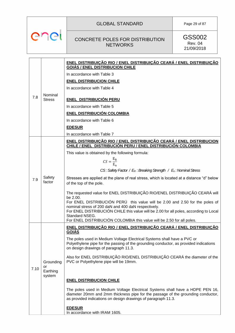
7.8 Nominal Stress
ENEL DISTRIBUIÇÃO RIO / ENEL DISTRIBUIÇÃO CEARÁ / ENEL DISTRIBUIÇÃO GOIÁS / ENEL DISTRIBUCION CHILE
In accordance with Table 3
ENEL DISTRIBUCION CHILE
In accordance with Table 4
ENEL DISTRIBUCIÓN PERU
In accordance with Table 5
ENEL DISTRIBUCIÓN COLOMBIA
In accordance with Table 6
EDESUR
In accordance with Table 7
7.9 Safety factor
ENEL DISTRIBUIÇÃO RIO / ENEL DISTRIBUIÇÃO CEARÁ / ENEL DISTRIBUCION CHILE / ENEL DISTRIBUCIÓN PERU / ENEL DISTRIBUCIÓN COLOMBIA
This value is obtained by the following formula:
𝐶𝑆 =EREn
CS : Safety Factor / ER : Breaking Strength / En : Nominal Stress
Stresses are applied at the plane of real stress, which is located at a distance “d” below
of the top of the pole.
The requested value for ENEL DISTRIBUIÇÃO RIO/ENEL DISTRIBUIÇÃO CEARÁ will be 2.00. For ENEL DISTRIBUCIÓN PERÚ this value will be 2.00 and 2.50 for the poles of nominal stress of 200 daN and 400 daN respectively. For ENEL DISTRIBUCIÓN CHILE this value will be 2.00 for all poles, according to Local Standard NSEG. For ENEL DISTRIBUCIÓN COLOMBIA this value will be 2.50 for all poles.
7.10
Grounding or Earthing system
ENEL DISTRIBUIÇÃO RIO / ENEL DISTRIBUIÇÃO CEARÁ / ENEL DISTRIBUIÇÃO GOIÁS
The poles used in Medium Voltage Electrical Systems shall have a PVC or Polyethylene pipe for the passing of the grounding conductor, as provided indications on design drawings of paragraph 11.3. Also for ENEL DISTRIBUIÇÃO RIO/ENEL DISTRIBUIÇÃO CEARÁ the diameter of the PVC or Polyethylene pipe will be 19mm.
ENEL DISTRIBUCION CHILE
The poles used in Medium Voltage Electrical Systems shall have a HDPE PEN 16, diameter 20mm and 2mm thickness pipe for the passage of the grounding conductor, as provided indications on design drawings of paragraph 11.3.
EDESUR In accordance with IRAM 1605.

GLOBAL STANDARD Page 30 of 87
CONCRETE POLES FOR DISTRIBUTION NETWORKS
GSS002 Rev. 04
21/09/2018
ENEL DISTRIBUCION COLOMBIA Concrete posts must have a plate or other metallic element with a section not less than 78 mm2, located less than one meter from the burial mark, which serves as an electrical contact between the steel of the pole frame and the external grounding connection.
7.11
Marking and designation of pole
The poles shall submit a recorded identification (labeling) directly on the concrete, legibly and indelibly, located according to design drawings. Shall be considered the following information: Date of manufacture, nominal length, nominal stress, manufacturer´s name, name of the distribution company. Also poles shall submit the following marks:
Signage to 3m, measured from the butt.
Mark of embedment height.
Mark of center gravity. For ENEL DISTRIBUCIÓN PERU additionally shall be included:
Diameter of the top. For ENEL DISTRIBUCIÓN COLOMBIA additionally shall be included:
Manufacturing date dd-mm-yy.
Weight of pole.
The word “BOG-CUN” and the purchase order.
Value of Breaking Strength For ENEL DISTRIBUIÇÃO RIO/ENEL DISTRIBUIÇÃO CEARÁ / ENEL DISTRIBUIÇÃO GOIÁS additionally shall be included:
Serial number Should be identified with paint on pole butt section at least the information: Length, rated load and date of manufacture.
For ENEL DISTRIBUCION CHILE additionally shall be included:
• Manufacturing date dd-mm-yy.
• Weight of pole.
• "Identification plate for Poles" with serial number as standard for "Marking Concrete
Poles”.
• Mark of center gravity
. Mark of embedment height.
7.13 Lifetime The poles manufactured under this specification shall have a minimum life of 35 years from the date of manufacturing, with a failure percentage of 1% for the first 10 years and 1% for each 5 subsequent years, totaling 6% at the end of period.

GLOBAL STANDARD Page 31 of 87
CONCRETE POLES FOR DISTRIBUTION NETWORKS
GSS002 Rev. 04
21/09/2018
8.2.2
List of type tests
N° TEST REQUIREMENT TEST METHOD
Materials Quality
A Concrete additive materials
Values required by standards specified in section 4.2
B Metal reinforcement steel
Values required by standards specified in section 4.2
Manufacturing Quality
C Compressive resistance of concrete
Values required by standards specified in section 4.2
D Concrete coating
ENEL DISTRIBUCIÓN COLOMBIA Required thickness : 20 mm ENEL DISTRIBUIÇÃO RIO/ENEL DISTRIBUIÇÃO CEARÁ / ENEL DISTRIBUIÇÃO GOIÁS Required thickness : 15mm for longitudinal and transversal measurements. 20mm for the top of the pole. ENEL DISTRIBUCION CHILE Required thickness : 20mm ENEL DISTRIBUCIÓN PERU Required thickness : 20mm (En = 200) 25mm (En = 400)
Typically the verification is performed on poles that were tested to break. Found 5 points along the pole exposing the rebar, by some mechanical means, then measured at each point concrete thickness with a gauge accurate to 1mm. This verification may be performed by non-destructive process.
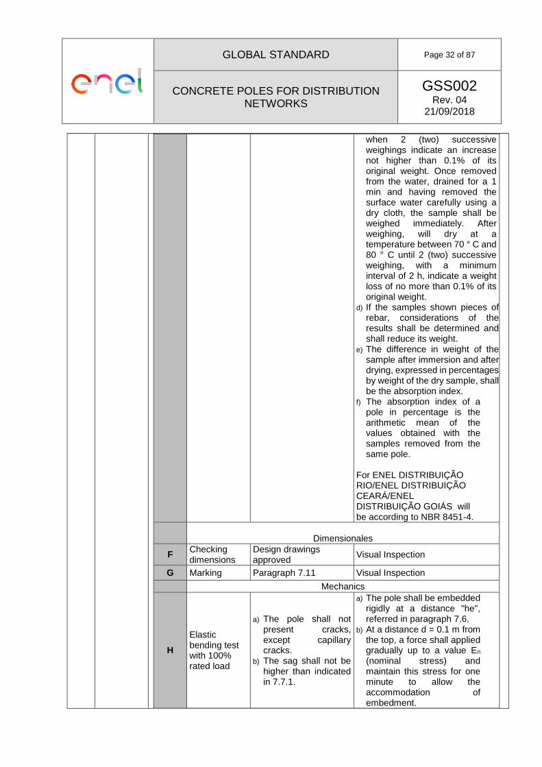
E Test water absorption index
a) 6% of the average of the samples
b) 7.5% to test pole For ENEL DISTRIBUIÇÃO RIO/ENEL DISTRIBUIÇÃO CEARÁ/ ENEL DISTRIBUIÇÃO GOIÁS: a) ≤ 5.5% of the average
of the samples b) ≤ 7.0% to test pole
a) The samples for absorption tests are removed after breaking test. After each broken pole is removed 4 concrete blocks without apparent cracks, whose linear dimensions are four to ten times greater than the maximum diameter of the aggregate used in the production of concrete.
b) Samples are marked with the same number or identification mark of the poles that were removed.
c) The samples are immersed in water, in a suitable vessel, at ambient temperature, for a minimum 30h, or until constant weight is maintained, that is,
GLOBAL STANDARD Page 32 of 87
CONCRETE POLES FOR DISTRIBUTION NETWORKS
GSS002 Rev. 04
21/09/2018
when 2 (two) successive weighings indicate an increase not higher than 0.1% of its original weight. Once removed from the water, drained for a 1 min and having removed the surface water carefully using a dry cloth, the sample shall be weighed immediately. After weighing, will dry at a temperature between 70 ° C and 80 ° C until 2 (two) successive weighing, with a minimum interval of 2 h, indicate a weight loss of no more than 0.1% of its original weight.
d) If the samples shown pieces of rebar, considerations of the results shall be determined and shall reduce its weight.
e) The difference in weight of the sample after immersion and after drying, expressed in percentages by weight of the dry sample, shall be the absorption index.
f) The absorption index of a pole in percentage is the arithmetic mean of the values obtained with the samples removed from the same pole.
For ENEL DISTRIBUIÇÃO RIO/ENEL DISTRIBUIÇÃO CEARÁ/ENEL DISTRIBUIÇÃO GOIÁS will be according to NBR 8451-4.
Dimensionales
F Checking dimensions
Design drawings approved
Visual Inspection
G Marking Paragraph 7.11 Visual Inspection Mechanics
H
Elastic bending test with 100% rated load
a) The pole shall not present cracks, except capillary cracks.
b) The sag shall not be higher than indicated in 7.7.1.
a) The pole shall be embedded rigidly at a distance "he", referred in paragraph 7.6.
b) At a distance d = 0.1 m from the top, a force shall applied gradually up to a value En (nominal stress) and maintain this stress for one minute to allow the accommodation of embedment.

GLOBAL STANDARD Page 33 of 87
CONCRETE POLES FOR DISTRIBUTION NETWORKS
GSS002 Rev. 04
21/09/2018
c) Release the applied load gradually and reapply a stress gradually until to achieve the value “En”, will maintain this stress for at least 5 minutes.
I Breaking strength test
a) This value shall be equal or greater than 200% rated load
Proceed similarly to the nominal load test but this time using a higher stress than “En” until cause the rupture of the pole.
ENEL DISTRIBUCION CHILE:
Figure 3: Scheme for testing bending moment

GLOBAL STANDARD Page 34 of 87
CONCRETE POLES FOR DISTRIBUTION NETWORKS
GSS002 Rev. 04
21/09/2018
ENEL DISTRIBUIÇÃO RIO / ENEL DISTRIBUIÇÃO CEARÁ/ ENEL DISTRIBUIÇÃO GOIÁS:
Figure 4: Scheme for testing bending moment
EDESUR
In accordance with IRAM 1605.

GLOBAL STANDARD Page 35 of 87
CONCRETE POLES FOR DISTRIBUTION NETWORKS
GSS002 Rev. 04
21/09/2018
8.3.1 Sampling plan (reception)
Table 10: Sample Size, and Acceptance Criteria – Dimensional tests
Distribution Company
Type of Sample
Inspection Level AQL
ENEL DISTRIBUIÇÃO
RIO/ENEL DISTRIBUIÇÃO CEARÁ/ ENEL DISTRIBUIÇÃO
GOIÁS
Double, according to NBR 8451-1 Table 7 and
Table 9
I 1.5% 4.0% 10.0%
ENEL DISTRIBUCIÓN
COLOMBIA Single II 4.0%
ENEL DISTRIBUCIÓN
PERU
According to NTP 339.027
ENEL DISTRIBUCIÓN
CHILE According to PDAR-3011
EDESUR Double
S-2 y S-3(Normal) 4.0%
S-4 (Simplification) 4.0%
S-3 (Strict) 6.5%
Table 11 :Sample Size, and Acceptance Criteria – Mechanical tests
Distribution Company
Type of Sample
Inspection Level AQL
ENEL DISTRIBUIÇÃO
RIO/ENEL DISTRIBUIÇÃO CEARÁ / ENEL DISTRIBUIÇÃO
GOIÁS
Single, according to NBR 8451-1 Table 8 and Table 10 1
S-3 1.5% 4.0%
ENEL DISTRIBUCIÓN
COLOMBIA 2 Single S-3 4.0%
ENEL DISTRIBUCIÓN
PERU According to NTP 339.027
ENEL DISTRIBUCIÓN
CHILE According to PDAR-3011
EDESUR Double
S-2 y S-3(Normal) 4.0%
S-4 (Simplification) 4.0%
S-3 (Strict) 6.5%
GLOBAL STANDARD Page 36 of 87
CONCRETE POLES FOR DISTRIBUTION NETWORKS
GSS002 Rev. 04
21/09/2018
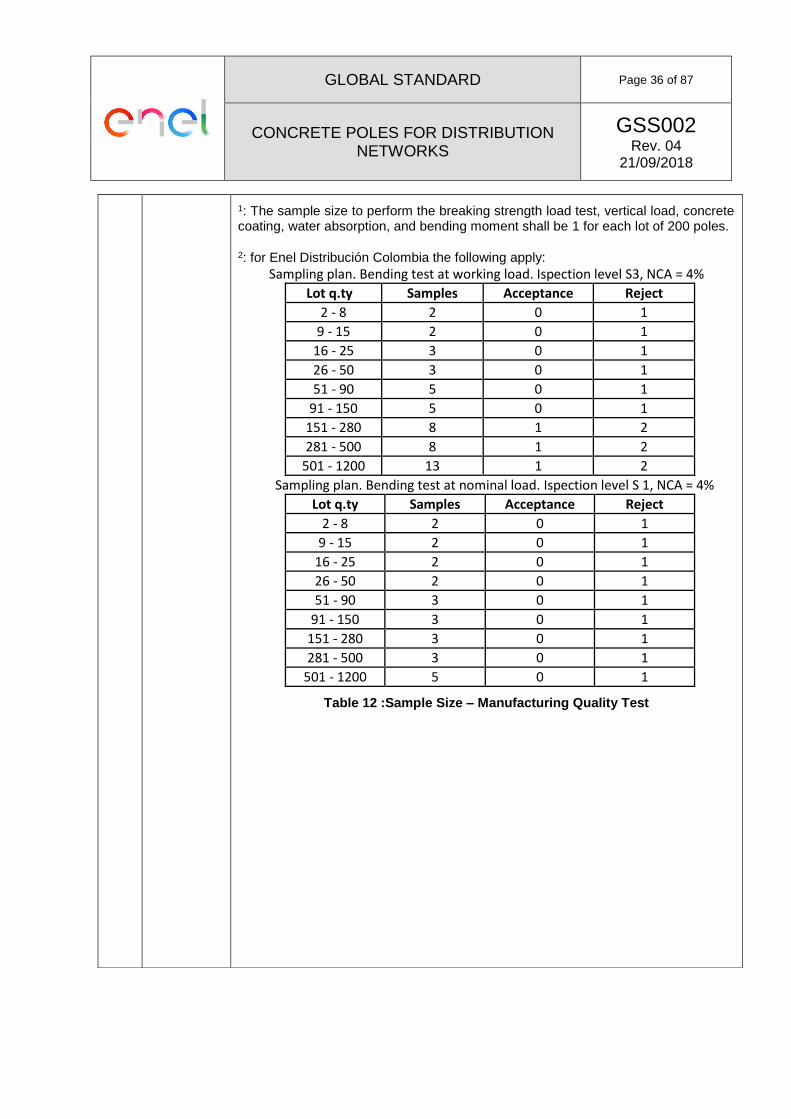
1: The sample size to perform the breaking strength load test, vertical load, concrete coating, water absorption, and bending moment shall be 1 for each lot of 200 poles.
2: for Enel Distribución Colombia the following apply: Sampling plan. Bending test at working load. Ispection level S3, NCA = 4%
Lot q.ty Samples Acceptance Reject
2 - 8 2 0 1
9 - 15 2 0 1
16 - 25 3 0 1
26 - 50 3 0 1
51 - 90 5 0 1
91 - 150 5 0 1
151 - 280 8 1 2
281 - 500 8 1 2
501 - 1200 13 1 2
Sampling plan. Bending test at nominal load. Ispection level S 1, NCA = 4%
Lot q.ty Samples Acceptance Reject
2 - 8 2 0 1
9 - 15 2 0 1
16 - 25 2 0 1
26 - 50 2 0 1
51 - 90 3 0 1
91 - 150 3 0 1
151 - 280 3 0 1
281 - 500 3 0 1
501 - 1200 5 0 1
Table 12 :Sample Size – Manufacturing Quality Test

GLOBAL STANDARD Page 37 of 87
CONCRETE POLES FOR DISTRIBUTION NETWORKS
GSS002 Rev. 04
21/09/2018
Distribution Company
Lot or Batch Size
Sample Size
Enel Distribuição Rio / Enel
Distribuição Ceará / Enel Distribuição
Goiás
200 2
Enel Distribución
Chile
60 - 120 1
According to PDAR-3011
Enel Distribución
Colombia 50 - 150 3
Enel Distribución
Peru 200 1
Edesur 200 1

GLOBAL STANDARD Page 38 of 87
CONCRETE POLES FOR DISTRIBUTION NETWORKS
GSS002 Rev. 04
21/09/2018
8.4 Other tests
ENEL DISTRIBUIÇÃO RIO / ENEL DISTRIBUIÇÃO CEARÁ / ENEL DISTRIBUIÇÃO GOIÁS
In addition.
N° TEST REQUIREMENT TEST METHOD
1 Mechanics
1.1
Elastic bending test with 140% rated load
a) The pole shall not
present cracks, except capillary cracks.
b) The sag shall not be higher than indicated in 7.7.1 and 7.7.2
c) Residual sag is the sag that remains after removing the stresses, indicated in 7.7.2
a) The pole shall be
embedded rigidly at a distance "he", referred in paragraph 7.6.
b) At a distance according item 7.7.1 from the top, a force shall applied gradually up to a value En (nominal stress) and maintain this stress for 3 minutes to allow the accommodation of embedment.
c) Apply a stress gradually until to achieve the value 1.4xEn, will maintain this stress for at least 3 minutes.
1.2 Bending Moment Test
a) The pole shall not present cracks under specified load.
According to NBR 8451-3

GLOBAL STANDARD Page 39 of 87
CONCRETE POLES FOR DISTRIBUTION NETWORKS
GSS002 Rev. 04
21/09/2018
11.3
Design drawing
ENEL DISTRIBUIÇÃO RIO / ENEL DISTRIBUIÇÃO CEARÁ / ENEL DISTRIBUIÇÃO GOIÁS:
Figure 5: General geometry of pole type HV

GLOBAL STANDARD Page 40 of 87
CONCRETE POLES FOR DISTRIBUTION NETWORKS
GSS002 Rev. 04
21/09/2018
Figure 6: General construction details of pole type HV

GLOBAL STANDARD Page 41 of 87
CONCRETE POLES FOR DISTRIBUTION NETWORKS
GSS002 Rev. 04
21/09/2018
Figure 7: Marking details of pole type HV

GLOBAL STANDARD Page 42 of 87
CONCRETE POLES FOR DISTRIBUTION NETWORKS
GSS002 Rev. 04
21/09/2018
Figure 8: General geometry of pole type HCV

GLOBAL STANDARD Page 43 of 87
CONCRETE POLES FOR DISTRIBUTION NETWORKS
GSS002 Rev. 04
21/09/2018
11.3 Design drawing
ENEL DISTRIBUCIÓN PERU:
Figure 8: Centrifuged Concrete Pole – Low Voltage Overhead Lines
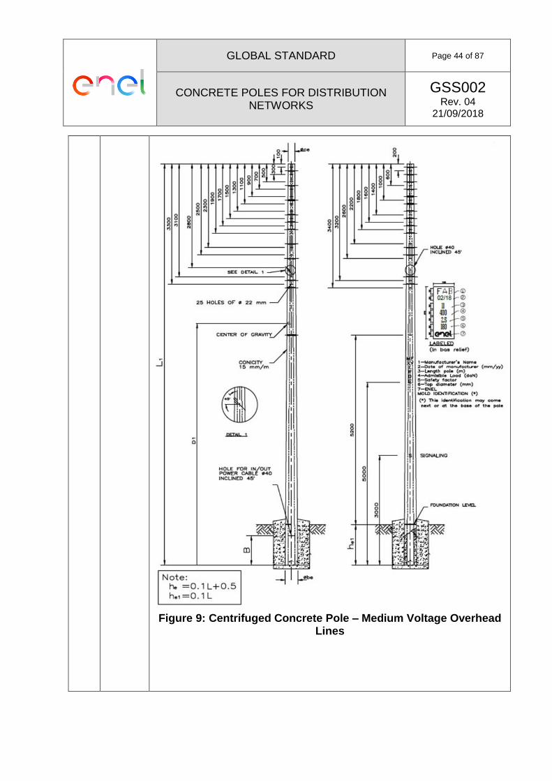
GLOBAL STANDARD Page 44 of 87
CONCRETE POLES FOR DISTRIBUTION NETWORKS
GSS002 Rev. 04
21/09/2018
Figure 9: Centrifuged Concrete Pole – Medium Voltage Overhead Lines

GLOBAL STANDARD Page 45 of 87
CONCRETE POLES FOR DISTRIBUTION NETWORKS
GSS002 Rev. 04
21/09/2018
11.3 Design drawing
ENEL DISTRIBUCIÓN COLOMBIA:
Figure 10: Pre-stressed Conical Frustum Pole – Medium/Low Voltage Overhead Lines

GLOBAL STANDARD Page 46 of 87
CONCRETE POLES FOR DISTRIBUTION NETWORKS
GSS002 Rev. 04
21/09/2018
Figure 11: Pre-stressed Conical Frustum Pole – Underground Lines for street lighting (AP)
GLOBAL STANDARD Page 47 of 87
CONCRETE POLES FOR DISTRIBUTION NETWORKS
GSS002 Rev. 04
21/09/2018
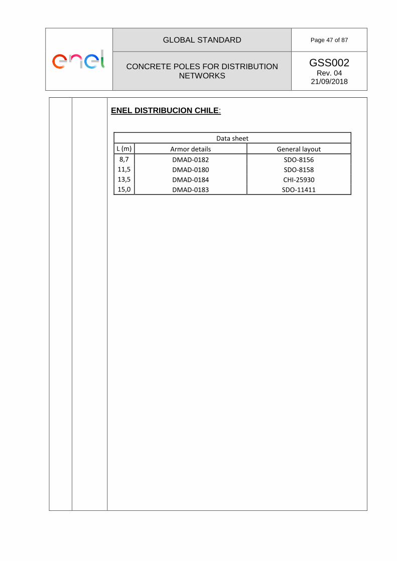
ENEL DISTRIBUCION CHILE:
Data sheet
L (m) Armor details General layout
8,7 DMAD-0182 SDO-8156
11,5 DMAD-0180 SDO-8158
13,5 DMAD-0184 CHI-25930
15,0 DMAD-0183 SDO-11411

GLOBAL STANDARD Page 48 of 87
CONCRETE POLES FOR DISTRIBUTION NETWORKS
GSS002 Rev. 04
21/09/2018

GLOBAL STANDARD Page 49 of 87
CONCRETE POLES FOR DISTRIBUTION NETWORKS
GSS002 Rev. 04
21/09/2018
Figure 12: General dimensions for poles type HV – 8.7m and 11.5m

GLOBAL STANDARD Page 50 of 87
CONCRETE POLES FOR DISTRIBUTION NETWORKS
GSS002 Rev. 04
21/09/2018

GLOBAL STANDARD Page 51 of 87
CONCRETE POLES FOR DISTRIBUTION NETWORKS
GSS002 Rev. 04
21/09/2018
Figure 13: General dimensions for poles type HV – 13.5m and 15m
ENEL DISTRIBUIÇÃO RIO:

GLOBAL STANDARD Page 52 of 87
CONCRETE POLES FOR DISTRIBUTION NETWORKS
GSS002 Rev. 04
21/09/2018
Figure 14: General dimensions for poles HV

GLOBAL STANDARD Page 53 of 87
CONCRETE POLES FOR DISTRIBUTION NETWORKS
GSS002 Rev. 04
21/09/2018
B. LOCAL SECTION – ENDESA DISTRIBUCIÓN ELÉCTRICA (SPAIN)
ITEM
TITLE
DESCRIPTION
2 DEFINITIONS
Reinforced Pole:
A pole designed to withstand the nominal stress "En" at a distance "d=0.25m" below the top (Cogolla) or a useful stress “K x En” at a distance "h5" above the top (Cogolla) that represent the position of the resultant of applied stresses.
To h5 = 0,75 m; K = 0,9
For other values of h5, K = 5,4 / (h5 + 5,25)
HV poles are reinforced
Nominal Stress or admissible load, En (complement)
In addition to the general section, this stress will apply at a distance “d=0.25m” below the top (cogolla) and simultaneously with the resulting stress from the pressure of 100 daN / m2 exerted by the wind in the same direction on the free surface of the pole.
Secondary stress (Es) (complement)
In addition to the general section, this stress will apply at a distance “d=0.25m” below the top (cogolla) with the same safety factor applied to nominal stress and without wind load consideration.
Global Safety Factor at break
Ratio between the breaking torque and service torque of a determined section.
4.1 International standards
EN 197-1 : Cement – Part 1: Composition, specifications and
conformity criteria for common cements.
EN 353-1 : Personal protective equipment against falls from a
height – Part 1: Guided type fall arresters including
a rigid anchor line.
EN 353-2 : Personal protective equipment against falls from a
height – Part 2: Guided type fall arresters including
a flexible anchor line.
EN 934-2 : Admixtures from a concrete, mortar and grout –
Part 2: Concrete admixtures – Definitions,
requirements, conformity, marking and labeling.
EN 1008 : Mixing water for concrete – Specification for
sampling, testing and assessing the suitability of
water, including water recovered from processes in
the concrete industry, as mixing water for concrete.

GLOBAL STANDARD Page 54 of 87
CONCRETE POLES FOR DISTRIBUTION NETWORKS
GSS002 Rev. 04
21/09/2018
EN 10080 : Steel for the reinforcement concrete – Weldable
reinforcing steel – General.
EN 12620 : Aggregates for concrete.
EN 12843 : Precast concrete products – Mast and poles.
EN 12878 : Pigments for the colouring of building materials
based on cement and/or lime – Specifications and
methods of test.
EN 13369 : Common rules for precast concrete products.
4.2 Local Standards
UNE 207016 : Postes de hormigón tipo HV y HVH para líneas
eléctricas aéreas.
UNE 17024 : Tirafondos de cabeza redonda con ranura recta.
Real decreto 223/2008, de 15 de febrero por el que se aprueba
el reglamento sobre condiciones técnicas y
garantías de seguridad en líneas eléctricas de
alta tensión y sus instrucciones técnicas
complementarias ITC-LAT 01 a 09.
DMAD-0182 / SDO-8156 Poste de Hormigón Armado de 8,7m
DMAD-0180 / SDO-8158 Poste de Hormigón Armado de 11,5m
DMAD-0184 / CHI-25930 Poste de Hormigón Armado de 13,5m
DMAD-0183 / SDO-11411 Poste de Hormigón Armado de 15,0m
PDAR-3011 Procedimiento de ensayos de recepción a postes en fábrica
CMD-14161 Cancha para ensayes
4.3
List of replaced Local Standards
AND00200 : POSTES DE HORMIGON ARMADO VIBRADO (HV)

GLOBAL STANDARD Page 55 of 87
CONCRETE POLES FOR DISTRIBUTION NETWORKS
GSS002 Rev. 04
21/09/2018
7.1 Manufactu
ring materials
Tests /Requirements
Cement CE marking (UNE-EN 197-1)
Requirements EHE (Code on Structural Concrete)
Gravel
(Aggregates)
CE marking (UNE-EN 12620)
Requirements EHE (Code on Structural Concrete)
Water UNE-EN 1008
Steel UNE-EN 10080
Requirements EHE (Code on Structural Concrete)
Additives CE marking (UNE-EN 934-2)
Requirements EHE (Code on Structural Concrete)
Pigments UNE-EN-12878
Requirements EHE (Code on Structural Concrete)
Concrete
UNE-EN 13369
UNE-EN 12843
UNE 207016
7.2 Dimension
s
The poles to use shall be of the reinforced type.
Table 13 shows lengths and nominal stress for selected concrete
poles:
Table 13: Lengths and Nominal Stresses
Length (m) Nominal Stress (daN)
250 400 630 800 1000 1600
9 X X X X X
11 X X X X X X
13 X X X X X X
15 X X
Table 14, shows the nominal and secondary stress with their global
safety factor at break and the breaking torque. In Table 15, nominal
dimensions of the top for each length and stress level of the poles
are established.
Table 14: Stresses and Safety factors
Nominal Secondary Breaking torsional
stress (daN x m)
En (daN) Safety Factor Es (daN) Safety Factor
250 2.25 160 2.25 -

GLOBAL STANDARD Page 56 of 87
CONCRETE POLES FOR DISTRIBUTION NETWORKS
GSS002 Rev. 04
21/09/2018
400 2.25 250 2.25 -
630 2.25 360 2.25 -
800 2.25 400 2.25 - 1000 2.25 500 2.25 540
1600 2.25 600 2.25 540
Table 15 : Nominal dimensions of the Top (Cogolla)
Nominal Stress, En
(daN)
Measurement of the Top (mm x mm)
Length (m)
9 11 13 15
250 110 x 145 X X X
400
140 x 200
X X X
630 X X X
800 X X X X
1000 170 x 255
X X X X
1600 X X
The conicity adopted to the wide face should be (21 ± 2) mm/m
and to the narrow face (13 ± 2) mm/m.
The general geometry of the pole type HV is shown in section 11.3
of this Appendix where the dimensions of the main sections are
detailed.
7.4 Holes The arrangement of the holes required in each of the faces, as other
particulars are shown in Figure 21. These holes will have a diameter
of 18 mm (± 0.7 mm).
7.6 Embedment length
The theoretical embedment length will corresponds to the following
formula: he = 0,1 L + 0,5
7.8 Nominal Stress
They are shown in Table 13.
7.9 Safety factor
Is determined by the global safety factor at break (CS), which must have a minimum value of 2.25. This value is obtained according the loading capacity test defined in paragraph 5.2.2 from standard UNE 207016.
7.10
Grounding or
Earthing system
The poles have two identical grounding terminals, on the same narrow face of the pole.
In Figure 15 the shape and arrangement of the ground terminals are detailed.
The screw with strength class 5.6 and the 50 mm × 50 mm plate, shall be galvanized. The screw shall be provided installed on the pole.

GLOBAL STANDARD Page 57 of 87
CONCRETE POLES FOR DISTRIBUTION NETWORKS
GSS002 Rev. 04
21/09/2018
The rebar earthing welding will be at least 30 mm long and continuous in two sections.
The upper terminal will be located at 2.10 m ± 0.05 m from the pole top (cogolla).
The lower terminal will be located at the distance ht from the base, as shown in Table 16 for the HV type poles with a tolerance of ± 0.05 m.
Electrical continuity shall exist between the two terminals.
Figure 15: Shape and Arrangement of Grounding Terminals
Table 16 : ht distance, from the lower earthing terminal to the pole bottom
Nominal Stress En
(daN)
Length (m)
9 11 13 15
250 2.00 2.10 2.30 -
400 2.20 2.30 2.50 -
630 2.20 2.30 2.50 -
800 2.20 2.30 2.50 2.60
1000 2.30 2.40 2.50 2.60
1600 - 2.40 2.50 -

GLOBAL STANDARD Page 58 of 87
CONCRETE POLES FOR DISTRIBUTION NETWORKS
GSS002 Rev. 04
21/09/2018
7.11
Marking
and designation of pole
Marking
Poles should come equipped with an engraved plate which records, indelibly and easily legible, in addition to what was indicated in paragraph ZA.3.1.1 (simplified label) of UNE-EN 12843 Standard, the content shown in Figure 16.
The plate measures and design must be according to Figure 16 and shall have a thickness between 0.6 mm to 0.8 mm, consist of anodized aluminum, and shall be installed at 4 m ± 0.20 m from the pole butt.
It shall be fixed in the concrete through curled edges, claws or others providing similar hooking.
For easy poles identification, the top (cogolla) shall be painted, as shown in Figure 17 with the color code specified in Table 17.
Figure 16: Characteristics plate
Figure 17: Painted of the top (Cogolla)

GLOBAL STANDARD Page 59 of 87
CONCRETE POLES FOR DISTRIBUTION NETWORKS
GSS002 Rev. 04
21/09/2018
Table 17: Identification color for poles type HV
Nominal Stress, En (daN)
Identification Colors
250 Black
400 Blue
630 Red
800 Yellow
1000 Green
1600 White
Designation:
The reinforced vibrated concrete poles for overhead power lines are designated by acronyms arranged in the following order and with the following meaning:
Acronym HV, indicative of the pole type, in this case reinforced vibrated concrete pole.
Figure, in daN, representing the nominal stress value En.
Acronym R, indicative of the reinforced pole.
Figure, in meters, representing the pole length.
Example: HV 1000 R 13 Pole type HV of 1000 daN nominal stress, reinforced, and with a total length of 13 meters. Electrical hazards signaling:
Electrical hazards signaling shall be made by the electrical hazard sign shown in Figure 18 stamped on the concrete. The mark shall be formed with the same concrete which is an integral part of the pole and shall be made during the same manufacturing process, in order to be integrated as a uniform part of the pole. This mark will be located about 0.20 m below the characteristics plate.

GLOBAL STANDARD Page 60 of 87
CONCRETE POLES FOR DISTRIBUTION NETWORKS
GSS002 Rev. 04
21/09/2018
Figure 18: Electrical hazards stamped signaling (measures in
mm)
Moreover, in order to foresee the installation of electric hazard signal shown in Figure 19, two plastic anchors shall be placed, embedded in the concrete, suitable for round head lag screws 3x18 according to UNE 17024 standard. These plastic anchors will be arranged on the narrow face axis of the pole, at a distance of 0,5m ± 0,05m above the characteristics plate and with a 154mm ± 2mm spacing between them.
Figure 19: Electric hazard warning plate (measures in mm)

GLOBAL STANDARD Page 61 of 87
CONCRETE POLES FOR DISTRIBUTION NETWORKS
GSS002 Rev. 04
21/09/2018
7.12
Safety line.
Concrete poles for overhead power lines should be foreseen and comply with the use of a safety line. The safety line shall comply with the standard UNE-EN 353. The poles shall be justified by calculation for a global safety factor at break not less than 1.5 in any of the following suppositions:
A vertical stress in safety line anchor point of 600 daN simultaneous with a horizontal stress in the secondary direction equal to ES (defined in Table 14)
A vertical stress in safety line anchor point of 600 daN simultaneous with a horizontal stress in the main direction equal to En (defined in Table 14).
The upper safety line anchor point shall not be located closer than 170 mm from the pole top (Cogolla). The safety line anchor device will have a design such that the maximum spacing between the application point of falling force and the face of pole on which it is held, shall be 100 mm.
8.2.1
Sampling plan (type)
Tests are performed on randomly selected lots that shall include a pole of each type and samples of materials used.
8.2.2
List of type tests
TEST REQUIREMENT TEST METHOD
Materials Quality
A Concrete constituent materials
UNE-EN 13369, paragraph 4.1.2 Requirement EHE
Documentary, compliance requirements by the supplier
B Metal reinforcement steel
UNE-EN 13369, paragraph 4.1.3 Requirement EHE
Supplier specifications
Manufacturing Quality
C Concrete compressive strength
UNE-EN 12843, paragraph 4.2 UNE 207016, paragraph 4.1
According to UNE-EN 13369, paragraph 5.1.1
D Concrete Coating UNE 207016, paragraph 4.2.3
Measurement according to UNE-EN 12843, paragraph 5.4
Dimensional
F Dimensional checking
UNE-EN 12843, paragraph 4.3.1 UNE 207016, paragraph 4.2.1
Measurement according to UNE 207016, paragraph 5.1
G Marking UNE-EN 12843, paragraph 7 UNE 207016, paragraph 7
Visual
Mechanics
H Elastic bending test
UNE 207016, paragraph 5.2.1.3
According to UNE-EN 12843, paragraph 5.5.2.2
According to UNE 207016, paragraph 5.2.1.2
I Breaking strength test (Loading capacity test)
UNE 207016, paragraph 5.2.2.1
According to UNE-EN 12843, paragraph 5.5.3 According to UNE 207016, paragraph 5.2.2

GLOBAL STANDARD Page 62 of 87
CONCRETE POLES FOR DISTRIBUTION NETWORKS
GSS002 Rev. 04
21/09/2018
J Torsional test UNE 207016, paragraph 5.2.3.3
According to UNE-EN 12843, paragraph 5.5.4
According to UNE 207016, paragraph 5.2.3
K Checking secondary stress
UNE 207016, paragraph 5.2.4.1
According to UNE 207016, paragraph 5.2.4
Others
L Grounding or Earthing Terminals
UNE-EN 12843, paragraph 4.3.9
UNE 207016, paragraph 4.2.4
Visual
Electrical continuity between upper and lower terminals Verification
8.3.1
Sampling plan (reception)
The manufacturer must have the testing and measurement equipment as set out in UNE207016 section 6.2.1 - Table 11.
Sampling plan:
On the 4% of the lot, with a minimum of two poles, the following tests will be performed:
Dimensional checking. Marking. Nondestructive elastic bending test. Verification of earthing terminals continuity.
On the 1% of the lot the following tests will be performed:
Breaking strength test (loading capacity test).
Checking secondary stress.
Torsional Test
For orders under 50 poles, these tests will be carried out gathering different orders so that one pole will be tested for every 50 units. Only one of the three tests will be done, alternatively. These orders can be separated in time. For orders between 50 and 100 poles only one of the three tests will be done, up to 200 poles two tests will be done and for orders more than 200 poles the three tests will be done, alternatively.
Concrete Coating. This test will be always done when breaking strength test, secondary stress test or torsional test is carried out.
If a defect is detected during receiving, two additional tests will be carried out and, if a defect in the new samples is detected, the batch shall be rejected. If the two additional tests were favorable, the lot

GLOBAL STANDARD Page 63 of 87
CONCRETE POLES FOR DISTRIBUTION NETWORKS
GSS002 Rev. 04
21/09/2018
shall be accepted replacing the deficient pole.
If the number of defects found is two or more, the lot shall be rejected.
The manufacturer must have the records corresponding to materials inspection as stated in UNE 207016, section 6.2.1 - Table 12.
8.3.2
List of reception tests
The test to be performed, according to the sampling plan described in 8.3.1 are:
Checking dimensions. Marking. Nondestructive elastic bending test Verification of earthing terminals continuity. Breaking strength test (loading capacity test). Checking secondary stress. Torsional test Concrete Coating.
The test method and requirement are the same as detailed in section
8.2.2 (Type Tests)

GLOBAL STANDARD Page 64 of 87
CONCRETE POLES FOR DISTRIBUTION NETWORKS
GSS002 Rev. 04
21/09/2018
11.3
Design drawing
Figure 20: Overall geometrical configuration of pole type HV

GLOBAL STANDARD Page 65 of 87
CONCRETE POLES FOR DISTRIBUTION NETWORKS
GSS002 Rev. 04
21/09/2018
11.3
Design drawing
Figure 21: General construction details of pole type HV

GLOBAL STANDARD Page 66 of 87
CONCRETE POLES FOR DISTRIBUTION NETWORKS
GSS002 Rev. 04
21/09/2018
C. LOCAL SECTION – E-DISTRIBUZIONE (ITALY), ENEL DISTRIBUTIE: BANAT, DOBROGEA, MUNTENIA (ROMANIA).
ITEM
TITLE
DESCRIPTION
4.2 Local Standards
D.M. 3-06-68
EN 197-1 : 2011; EN 1992-1-1 : 2004; EN 206-1 : 2003
UNI EN ISO 6892 : 2009 – EN ISO 6892 : 2009
UNI EN 10080 : 2005 – EN 10080 : 2005
UNI EN 12350-1 : 2009 – EN 12350
UNI EN 12390-1 : 2012 – EN 12390-1 : 2012
UNI EN 12390-2 : 2009 – EN 12390-2 : 2009
UNI EN 12390-3 : 2009 – EN 12390-3 : 2009
CEI 7.6 – EN ISO 1461 : 2009
D.M. 14-1 : 2008
UNI EN 12843 : 2005 – EN 12843 : 2004
EN 197-1 : 2011
EN 206-1 : 2013
4.3
List of replaced Local Standards
DS 3000 – DS 3000 RO only for the centrifuged reinforced concrete poles without metal extensions
DS 3800 – DS 3800 RO only for the centrifuged reinforced concrete poles without metal extensions
DS 3801 – DS 3801 RO only for the centrifuged reinforced concrete poles without metal extensions
DS 3005 – DS 3005 RO only for the centrifuged reinforced concrete poles used as support for MV/LV transformer

GLOBAL STANDARD Page 67 of 87
CONCRETE POLES FOR DISTRIBUTION NETWORKS
GSS002 Rev. 04
21/09/2018
7.1 Manufacturing materials
Tests /Requirements
Cement
D.M. 3-06-68– EN 197-1:2011
EN 206-1:2013
EN 1992-1-1:2004
Steel
UNI 556 – EN ISO 6892:2009
UNI EN 10080: 2005 – EN 10080:2005
CEI 7.6 – EN ISO 1461:2009
Concrete
UNI EN 12350-1 : 2009 – EN 12350-1:2009
UNI EN 12390-1 : 2012 – EN 12390-1: 2012
UNI EN 12390-2 : 2009 – EN 12390-2:2009
UNI EN 12390-3 : 2009 – EN 12390-3:2009
D.M. 14-1:2008
UNI EN 12843:2005 – EN 12843:2004
7.2 Dimensio
ns
In Table 18 shows the different poles with the main nominal
dimensions according to their length and nominal stress.
Table 18 : Lengths and Nominal Stress
Type Length
(m) d
(mm) D
(mm) Theorical mass (Kg) Scheme
Tensile Test “T” at a distance “h” from application (measured from
the top of the pole)
"T1" (daN)
h1 (m)
"T2" (daN)
h2 (m)
A 10 120 270 620 1 412 0.1 -- --
B 10 140 290 720 1 550 0.1 -- -- 12 140 320 1000 1 550 0.1 227 9
C
10 1 180 330 950 1 824 0.1 -- -- 12 180 360 1270 2 824 0.1 265 9
D
10 200 350 1120 1 1091 0.1 -- -- 12 200 380 1460 2 1099 0.1 -- -- 14 200 410 1910 2 1099 0.1 220 10.8
E
10 240 390 1450 1 1638 0.1 -- -- 12 240 420 1900 2 1648 0.1 -- -- 14 240 450 2400 2 1648 0.1 402 10.8
F
10 270 420 1700 1 2188 0.1 -- -- 12 270 450 2250 2 2198 0.1 -- -- 14 270 480 2800 2 2198 0.1 263 10.8 10 310 460 2100 2 3286 0.1 -- --

GLOBAL STANDARD Page 68 of 87
CONCRETE POLES FOR DISTRIBUTION NETWORKS
GSS002 Rev. 04
21/09/2018
G
10 2 310 460 2100 2 3286 0.1 -- -- 12 310 490 2700 2 3296 0.1 -- -- 14
310 520 3400 2 3296 0.1 485 10.8
H 12 320 500 3600 2 6280 0.1 -- --
1 This pole could also be used as support for MV disconnectors
therefore, in order to perform earthing resistance tests and
measurement, an earthing circuit to be connected with the MV
disconnector chassis must be embedded in the pole and the
relevant earthing contact must be available at a height of 2,5 meters
to the ground.
2 This pole is used as support for MV/LV transformer (see local
standard DS3005 ed. 1 del 12/1999) therefore, in order to
perform earthing resistance tests and measurement, an earthing
circuit to be connected with the transformer tank must be embedded
in the pole and the relevant earthing contact must be available at a
height of 2,5 meters to the ground.
The general geometry of the pole type HC is shown in section 11.3
of this Appendix, the dimensions of the main sections are detailed.
In Figure 24 shown the general geometrical configuration of this type of pole. Low Voltage poles have simplest features and obey the scheme 1 of Figure 25. Poles to be used in MV/LV power lines obey the scheme 2 in Figure 25 and include additional features to system grounding.
In Table 18, the nominal measurements of the top and base diameter are established, theoretical mass, corresponding to the poles according to their length and nominal stress.
7.4 Holes The arrangement of the holes required on each of the faces, as other
particulars are shown in Figure 25, these holes shall have a diameter
of 22 mm.
7.6 Embedment length
The following formula shall be applied for embedment length:
he = 0,1 L
Where L is the nominal length of the pole. For poles type F and G,
minimum embedment length shall be 1.20 m.
7.8 Nominal Stress
It is determined by the tensile test or breaking strength ER, which is to be the result of the combination of two stresses T1 and T2 applied on two specific points of the pole at a distance 0.1 and h2 from the top of the pole, tabulated in Table 18, as shown in Figure 22.

GLOBAL STANDARD Page 69 of 87
CONCRETE POLES FOR DISTRIBUTION NETWORKS
GSS002 Rev. 04
21/09/2018
Figure 22: Upright scheme to stress applications T1 and T2
Figure 23: Horizontal scheme of stress applications T1 and T2
Nominal stress is considered 40% from Tensile Test or Breaking
Strength, value that be determined by safety factor. They are shown
in Table 18.
7.9 Safety factor
Safety factor (CS), once calculated shall result in a minimum value of 2.5. This value is obtained by the following formulation:
𝐶𝑆 =FRF
CS : Safety factor at break
FR : Tensile test or Break strength

GLOBAL STANDARD Page 70 of 87
CONCRETE POLES FOR DISTRIBUTION NETWORKS
GSS002 Rev. 04
21/09/2018
F : Nominal Stress
7.10
Grounding or Earthing system
It shall consist for two elements that are:
Cap (Fondello con bussola) of hot dipped galvanized steel, which is welded to the rebar ring from the top of the pole. The Cap hole shall not be eccentric, respect to the diameter from the top of the pole. The inner of cap shall be free at least 70 mm to let appropriate adjustment of the bolt. The depth of the cap shall be covered by a plastic cover. The pole arrangement shown in Figure 25 and Figure 26, detail “B”.
Lower hole to insert grounding system, composed of a steel insert as a blind hole on the edge of the outer surface located at the height of the pole embedment section. This insert is welded to the base ring. The location details are shown in Figure 25 and Figure 26 Detail “C”.
7.11
Marking and designation of pole
Marking The pole shall carry at 3m to the butt a stainless steel metal plate, solidly anchored to the concrete pole. Registration shall be in high or bas relief so that it can be readable the following information:
Builder Acronym
Acronym of the pole (height, type, diameter)
Year of manufacture This model can see in Figure 26 detail “A”
Designation
Centrifuged concrete poles for overhead power lines will be designated by groups of acronyms, arranged in the following order with the following meaning.
Acronyms PALO CAC, indicative of the type of pole, in this case Centrifuged Concrete Pole.
Acronyms that represents, in meters, the length of the pole.
Acronym that represents the type of the pole. The values range from A-H and L.
Acronyms that represents, in centimeters, the top’s diameter of the pole.
Example: PALO CAC – 10 / B / 14: Pole type CAC 10 m length, type “B” and 14 cm diameter from the top of the pole.

GLOBAL STANDARD Page 71 of 87
CONCRETE POLES FOR DISTRIBUTION NETWORKS
GSS002 Rev. 04
21/09/2018
8.2.1
Sampling plan (type)
The number of poles required, shall be the necessary to performs all the tests required in paragraph 8.2.2
8.2.2
List of type tests
TEST REQUIREMENT TEST METHOD
Materials Quality
A Visual inspection Checking erroneous characteristics on pole Visual inspection.
B Checking dimensions Check if tolerances are no exceed
Direct verification by means tools of the pole dimensions.
C Mass checking Checking values in Table 18 Consists at controlling the mass of each pole according to the reference value.
D Grounding or Earthing system verification
Consist of two tests : a) Mechanical strength test of the
lower insert, willing for grounding. Screw the normalized ground terminal in the hole provided and check if no occur faults in the immediate vicinity, then tighten with a dynamometric wrench a torque of 10 kg-m.
b) Checking on the electrical continuity of the connection between the top cap and the lower insert. It is performed applying a voltage between the cap and the insert to permit the current flow of not less than 20 A, so that the ratio between the applied voltage, expressed in volts, and the effective current, in amperes, is not greater than 0.05 ohms.
E Mechanic Resistance of bussola
a) The test is considered valid if it can achieve the required stress without the presence of lesions in the pole and bussola.
a) It shall apply gradually an equivalent stress equal to 1/3 of the tensile test "T1" (indicated in Table 18 for each type of pole) on a bolt of appropriate test, up to 800 kg. At half of this value fine cracks can appear, that are no longer visible when removing the load.
F Elastic Bending Test (with 40% Tensile Test)
a) In the maximum stress only shall occur capillary cracks, which disappear from view by removing the load.
a) It applies on the pole a stress T1 and T2 (in accordance with arrangement of Figure 22) divided by 2.5, for the time necessary to measure the displacement of the top section and the following sections, taken from 2 m to 2 m with respect to the initial position of the pole.
b) It shall be verified that during the implementation of stresses, the pole will act with a smooth curve without sharp points.
F Breaking Strength Test
a) Effective Breaking Strength is the recorded maximum reading just before the pole fracture.
a) Provide the pole according to the scheme shown in Figure 22 or that shown in Figure 23.
b) The interlocking or embedment length, shall be continuous, it enough to ensure that every stress shows no buckling.

GLOBAL STANDARD Page 72 of 87
CONCRETE POLES FOR DISTRIBUTION NETWORKS
GSS002 Rev. 04
21/09/2018
c) The values of T1, T2, h1, h2 are
characteristic to each tested pole and are tabulated in Table 18. The test considers the moment diagram of the effect arising due to the conductors and wind pressure.
d) The T2 stress shall be maintained constant during the test. Being T1 a variable stress, whose value shall gradually increase until achieve a value T1.
e) Successively will increase the stress on the top to achieve effective break of the pole.
f) The dynamometer used shall have accuracy not less than 3% of the T1 stress and the drive mechanism shall allow, a gradual stress increase, at 20% of the T1 stress.
G Metal reinforcement steel
According to UNI 556 EN ISO 6892 : 2009 According to UNI 6407 EN 12390-3 : 2009
According to UNI 556 EN ISO 6892 : 2009
H Welding Method According to UNI 556 EN ISO 6892 : 2009
According to UNI 556 EN ISO 6892 : 2009
I Compressive resistance of concrete
According to UNI 6130-72 EN 12390-1 : 2012
According to UNI 6126-72 EN 12350-1 : 2009
I Tensile Test for Rebar According to UNI 556 EN ISO 6892 : 2009
According to UNI 556 EN ISO 6892 : 2009
8.3.1
Sampling plan (reception)
Simple sampling type, acceptance level II and AQL of 2.5%
8.3.2
List of reception tests
The tests to be performed, according to the sampling plan described in 8.3.1 are:
Visual inspection.
Checking dimensions.
Mass verification
Grounding System check
Compressive resistance of concrete
Tensile Test for Metallic Reinforcement Steel
The test method and requirement are the same as detailed in section
8.2.2 (Type Tests)

GLOBAL STANDARD Page 73 of 87
CONCRETE POLES FOR DISTRIBUTION NETWORKS
GSS002 Rev. 04
21/09/2018
11.3
Design drawing
Figure 24: Overall geometrical configuration of pole type HC
L
d
D

GLOBAL STANDARD Page 74 of 87
CONCRETE POLES FOR DISTRIBUTION NETWORKS
GSS002 Rev. 04
21/09/2018
11.3
Design drawing
Figure 25: Poles LV/MV schemes
Figure 26: General construction details of pole type HC

GLOBAL STANDARD Page 75 of 87
CONCRETE POLES FOR DISTRIBUTION NETWORKS
GSS002 Rev. 04
21/09/2018
COMMON LIST OF MAIN REQUIREMENTS
CONCRETE POLES FOR DISTRIBUTION NETWORKS REFERENCE LIST is attached in the following.

GLOBAL STANDARD Page 76 of 87
CONCRETE POLES FOR DISTRIBUTION NETWORKS GSS002
Rev. 03 21/09/2018
Item
GS T
ype C
od
e
Distrib
utio
n C
om
pan
y an
d
Co
un
try
Co
un
try Co
de
Distrib
utio
n N
etwo
rk
Co
de T
ype o
f Po
le
No
min
al Len
gth
(m)
Typ
e
Descrip
tion
To
p A
rea (m
m x m
m)
Bu
tt Area
(mm
x mm
)
To
p D
iameter
(mm
)
Bu
tt Diam
eter (m
m)
Co
nicity fo
r Circu
lar po
les sectio
n
(mm
/m)
Prim
ary Co
nicity fo
r rectan
gu
lar po
les section
(n
arrow
face) (mm
/m)
Secon
dary C
on
icity for
rectangu
lar po
les section
(w
ide face) (m
m/m
)
Co
ating
(m
m)
Mass (K
g)
Nominal Stress
Tensile Test Secondary
Stress Break
ing Stren
gth
(d
aN x m
)
To
rsion
al Stress (d
aN x m
)
Ad
missib
le Lo
ad
(daN
)
Safety F
actor
T1
(d
aN)
T2
(d
aN)
h2
(m
)
Safety F
actor
Stress (d
aN)
Safety F
actor
1 GSS002/01 EE-Spain 6700355 MV /
LV HV 9 - HV 250 R 9 110 x 145 - - - - 13 ± 2 21 ± 2
Steel bars:
20mm, strips: 15mm
- 250 2,25 -
- - - 160 2,25 - -
2 GSS002/02 EE-Spain 6700356 MV /
LV HV 9 - HV 400 R 9 140 x 200 - - - - 13 ± 2 21 ± 2
Steel bars:
20mm, strips: 15mm
- 400 2,25 -
- - - 250 2,25 - -
3 GSS002/03 EE-Spain 6700357 MV /
LV HV 9 - HV 630 R 9 140 x 200 - - - - 13 ± 2 21 ± 2
Steel bars:
20mm, strips: 15mm
- 630 2,25 -
- - - 360 2,25 - -
4 GSS002/04 EE-Spain 6700358 MV /
LV HV 9 - HV 800 R 9 140 x 200 - - - - 13 ± 2 21 ± 2
Steel bars:
20mm, strips: 15mm
- 800 2,25 - - - - 400 2,25 - -
5 GSS002/05 EE-Spain 6700359 MV /
LV HV 9 - HV 1000 R 9 170 x 255 - - - - 13 ± 2 21 ± 2
Steel bars:
20mm, strips: 15mm
- 1000 2,25 -
- - - 500 2,25 - 540
6 GSS002/06 EE-Spain 6700670 MV /
LV HV 11 - HV 250 R 11 110 x 145 - - - - 13 ± 2 21 ± 2
Steel bars:
20mm, strips: 15mm
- 250 2,25 -
- - - 160 2,25 - -
7 GSS002/07 EE-Spain 6700360 MV /
LV HV 11 - HV 400 R 11 140 x 200 - - - - 13 ± 2 21 ± 2
Steel bars:
20mm, strips: 15mm
- 400 2,25 - - - - 250 2,25 - -
8 GSS002/08 EE-Spain 6700361 MV /
LV HV 11 - HV 630 R 11 140 x 200 - - - - 13 ± 2 21 ± 2
Steel bars:
20mm, strips: 15mm
- 630 2,25 - - - - 360 2,25 - -
9 GSS002/09 EE-Spain 6700362 MV /
LV HV 11 - HV 800 R 11 140 x 200 - - - - 13 ± 2 21 ± 2
Steel bars:
20mm, - 800 2,25 - - - - 400 2,25 - -

GLOBAL STANDARD Page 77 of 87
CONCRETE POLES FOR DISTRIBUTION NETWORKS GSS002
Rev. 03 21/09/2018
Item
GS T
ype C
od
e
Distrib
utio
n C
om
pan
y an
d
Co
un
try
Co
un
try Co
de
Distrib
utio
n N
etwo
rk
Co
de T
ype o
f Po
le
No
min
al Len
gth
(m)
Typ
e
Descrip
tion
To
p A
rea (m
m x m
m)
Bu
tt Area
(mm
x mm
)
To
p D
iameter
(mm
)
Bu
tt Diam
eter (m
m)
Co
nicity fo
r Circu
lar po
les sectio
n
(mm
/m)
Prim
ary Co
nicity fo
r rectan
gu
lar po
les section
(n
arrow
face) (mm
/m)
Secon
dary C
on
icity for
rectangu
lar po
les section
(w
ide face) (m
m/m
)
Co
ating
(m
m)
Mass (K
g)
Nominal Stress
Tensile Test Secondary
Stress Break
ing Stren
gth
(d
aN x m
)
To
rsion
al Stress (d
aN x m
)
Ad
missib
le Lo
ad
(daN
)
Safety F
actor
T1
(d
aN)
T2
(d
aN)
h2
(m
)
Safety F
actor
Stress (d
aN)
Safety F
actor
strips: 15mm
10 GSS002/10 EE-Spain 6700363 MV /
LV HV 11 - HV 1000 R 11 170 x 255 - - - - 13 ± 2 21 ± 2
Steel bars:
20mm, strips: 15mm
- 1000 2,25 - - - - 500 2,25 - 540
11 GSS002/11 EE-Spain 6700370 MV /
LV HV 11 - HV 1600 R 11 170 x 255 - - - - 13 ± 2 21 ± 2
Steel bars:
20mm, strips: 15mm
- 1600 2,25 - - - - 600 2,25 - 540
12 GSS002/12 EE-Spain 6700671 MV /
LV HV 13 - HV 250 R 13 110 x 145 - - - - 13 ± 2 21 ± 2
Steel bars:
20mm, strips: 15mm
- 250 2,25 - - - - 160 2,25 - -
13 GSS002/13 EE-Spain 6700371 MV /
LV HV 13 - HV 400 R 13 140 x 200 - - - - 13 ± 2 21 ± 2
Steel bars:
20mm, strips: 15mm
- 400 2,25 - - - - 250 2,25 - -
14 GSS002/14 EE-Spain 6700372 MV /
LV HV 13 - HV 630 R 13 140 x 200 - - - - 13 ± 2 21 ± 2
Steel bars:
20mm, strips: 15mm
- 630 2,25 - - - - 360 2,25 - -
15 GSS002/15 EE-Spain 6700373 MV /
LV HV 13 - HV 800 R 13 140 x 200 - - - - 13 ± 2 21 ± 2
Steel bars:
20mm, strips: 15mm
- 800 2,25 - - - - 400 2,25 - -
16 GSS002/16 EE-Spain 6700374 MV /
LV HV 13 - HV 1000 R 13 170 x 255 - - - - 13 ± 2 21 ± 2
Steel bars:
20mm, strips: 15mm
- 1000 2,25 - - - - 500 2,25 - 540
17 GSS002/17 EE-Spain 6700375 MV /
LV HV 13 - HV 1600 R 13 170 x 255 - - - - 13 ± 2 21 ± 2
Steel bars:
20mm, strips: 15mm
- 1600 2,25 - - - - 600 2,25 - 540

GLOBAL STANDARD Page 78 of 87
CONCRETE POLES FOR DISTRIBUTION NETWORKS GSS002
Rev. 03 21/09/2018
Item
GS T
ype C
od
e
Distrib
utio
n C
om
pan
y an
d
Co
un
try
Co
un
try Co
de
Distrib
utio
n N
etwo
rk
Co
de T
ype o
f Po
le
No
min
al Len
gth
(m)
Typ
e
Descrip
tion
To
p A
rea (m
m x m
m)
Bu
tt Area
(mm
x mm
)
To
p D
iameter
(mm
)
Bu
tt Diam
eter (m
m)
Co
nicity fo
r Circu
lar po
les sectio
n
(mm
/m)
Prim
ary Co
nicity fo
r rectan
gu
lar po
les section
(n
arrow
face) (mm
/m)
Secon
dary C
on
icity for
rectangu
lar po
les section
(w
ide face) (m
m/m
)
Co
ating
(m
m)
Mass (K
g)
Nominal Stress
Tensile Test Secondary
Stress Break
ing Stren
gth
(d
aN x m
)
To
rsion
al Stress (d
aN x m
)
Ad
missib
le Lo
ad
(daN
)
Safety F
actor
T1
(d
aN)
T2
(d
aN)
h2
(m
)
Safety F
actor
Stress (d
aN)
Safety F
actor
18 GSS002/18 EE-Spain 6701501 MV /
LV HV 15 - HV 800 R 15 140 x 200 - - - - 13 ± 2 21 ± 2
Steel bars:
20mm, strips: 15mm
- 800 2,25 - - - - 400 2,25 - -
19 GSS002/19 EE-Spain 6701502 MV /
LV HV 15 - HV 1000 R 15 170 x 255 - - - - 13 ± 2 21 ± 2
Steel bars:
20mm, strips: 15mm
- 1000 2,25 - - - - 500 2,25 - 540
20 GSS002/20 ED-Italy 230212 LV HC 10 A 10 / A / 12 - - 120 270 15 - - ≥15 620 - - 412 - - 2,5 - - - -
21 GSS002/21 ED-Italy 230222 LV HC 10 B 10 / B / 14 - - 140 290 15 - - ≥15 720 - - 550 - - 2,5 - - - -
22 GSS002/22 ED-Italy 230232 MV/LV HC 10 C 10 / C / 18 - - 180 330 15 - - ≥15 950 - - 824 - - 2,5 - - - -
23 GSS002/23 ED-Italy 230242 LV HC 10 D 10 / D / 20 - - 200 350 15 - - ≥15 1120 - - 1091 - - 2,5 - - - -
24 GSS002/24 ED-Italy 230252 LV HC 10 E 10 / E / 24 - - 240 390 15 - - ≥15 1450 - - 1638 - - 2,5 - - - -
25 GSS002/25 ED-Italy 230262 LV HC 10 F 10 / F / 27 - - 270 420 15 - - ≥15 1700 - - 2188 - - 2,5 - - - -
26 GSS002/26 ED-Italy 230272 LV HC 10 G 10 / G / 31 - - 310 460 15 - - ≥15 2100 - - 3286 - - 2,5 - - - -
27 GSS002/27 ED-Italy 230224 LV HC 12 B 12 / B / 14 - - 140 320 15 - - ≥15 1000 - - 550 227 9 2,5 - - - -
28 GSS002/28 ED-Italy 230234 MV /
LV HC 12 C 12 / C / 18 - - 180 360 15 - - ≥15 1270 - - 824 265 9 2,5 - - - -
29 GSS002/29 ED-Italy 230244 MV /
LV HC 12 D 12 / D / 20 - - 200 380 15 - - ≥15 1460 - - 1099 - - 2,5 - - - -
30 GSS002/30 ED-Italy 230254 MV /
LV HC 12 E 12 / E / 24 - - 240 420 15 - - ≥15 1900 - - 1648 - - 2,5 - - - -

GLOBAL STANDARD Page 79 of 87
CONCRETE POLES FOR DISTRIBUTION NETWORKS GSS002
Rev. 03 21/09/2018
Item
GS T
ype C
od
e
Distrib
utio
n C
om
pan
y an
d
Co
un
try
Co
un
try Co
de
Distrib
utio
n N
etwo
rk
Co
de T
ype o
f Po
le
No
min
al Len
gth
(m)
Typ
e
Descrip
tion
To
p A
rea (m
m x m
m)
Bu
tt Area
(mm
x mm
)
To
p D
iameter
(mm
)
Bu
tt Diam
eter (m
m)
Co
nicity fo
r Circu
lar po
les sectio
n
(mm
/m)
Prim
ary Co
nicity fo
r rectan
gu
lar po
les section
(n
arrow
face) (mm
/m)
Secon
dary C
on
icity for
rectangu
lar po
les section
(w
ide face) (m
m/m
)
Co
ating
(m
m)
Mass (K
g)
Nominal Stress
Tensile Test Secondary
Stress Break
ing Stren
gth
(d
aN x m
)
To
rsion
al Stress (d
aN x m
)
Ad
missib
le Lo
ad
(daN
)
Safety F
actor
T1
(d
aN)
T2
(d
aN)
h2
(m
)
Safety F
actor
Stress (d
aN)
Safety F
actor
31 GSS002/31 ED-Italy 230264 MV /
LV HC 12 F 12 / F / 27 - - 270 450 15 - - ≥15 2250 - - 2198 - - 2,5 - - - -
32 GSS002/32 ED-Italy 230274 MV /
LV HC 12 G 12 / G / 31 - - 310 490 15 - - ≥15 2700 - - 3296 - - 2,5 - - - -
33 GSS002/33 ED-Italy 230276 MV /
LV HC 12 H 12 / H / 32 - - 320 500 15 - - ≥15 3600 - - 6280 - - 2,5 - - - -
34 GSS002/34 ED-Italy 230245 MV /
LV HC 14 D 14 / D / 20 - - 200 410 15 - - ≥15 1910 - - 1099 220 10,8 2,5 - - - -
35 GSS002/35 ED-Italy 230255 MV /
LV HC 14 E 14 / E / 24 - - 240 450 15 - - ≥15 2400 - - 1648 402 10,8 2,5 - - - -
36 GSS002/36 ED-Italy 230265 MV /
LV HC 14 F 14 / F / 27 - - 270 480 15 - - ≥15 2800 - - 2198 263 10,8 2,5 - - - -
37 GSS002/37 ED-Italy 230275 MV /
LV HC 14 G 14 / G / 31 - - 310 520 15 - - ≥15 3400 - - 3296 485 10,8 2,5 - - - -
38 GSS002/38 ED-Italy 228010 MV HC 10 G 10 / G / 31 - - 310 460 15 - - ≥15 2100 - - 3286 - - 2,5 - - - -
39 GSS002/39 CD-
Colombia 6762449
MV / LV
HC/HCV 10 - 10 x 510 - - 140 290 15 - - 20 - 200 2,5 - - - - - - 500 -
40 GSS002/40 CD-
Colombia 6762457 LV HC/HCV 10 - 10 x 510 AP - - 170 320 15 - - 20 - 200 2,5 - - - - - - 500 -
41 GSS002/41 CD-
Colombia 6762450
MV / LV
HC/HCV 10 - 10 x 1050 - - 170 320 15 - - 20 - 412 2,5 - - - - - - 1030 -
42 GSS002/42 CD-
Colombia 6762451
MV / LV
HC/HCV 12 - 12 x 510 - - 140 320 15 - - 20 - 200 2,5 - - - - - - 500 -
43 GSS002/43 CD-
Colombia 6762448 LV
HC/HCV 12 - 12 x 510 AP - - 140 320 15 - - 20 - 200 2,5 - - - - - - 500 -
44 GSS002/44 CD-
Colombia 6762452
MV / LV
HC/HCV 12 - 12 x 750 - - 140 320 15 - - 20 - 294 2,5 - - - - - - 735 -

GLOBAL STANDARD Page 80 of 87
CONCRETE POLES FOR DISTRIBUTION NETWORKS GSS002
Rev. 03 21/09/2018
Item
GS T
ype C
od
e
Distrib
utio
n C
om
pan
y an
d
Co
un
try
Co
un
try Co
de
Distrib
utio
n N
etwo
rk
Co
de T
ype o
f Po
le
No
min
al Len
gth
(m)
Typ
e
Descrip
tion
To
p A
rea (m
m x m
m)
Bu
tt Area
(mm
x mm
)
To
p D
iameter
(mm
)
Bu
tt Diam
eter (m
m)
Co
nicity fo
r Circu
lar po
les sectio
n
(mm
/m)
Prim
ary Co
nicity fo
r rectan
gu
lar po
les section
(n
arrow
face) (mm
/m)
Secon
dary C
on
icity for
rectangu
lar po
les section
(w
ide face) (m
m/m
)
Co
ating
(m
m)
Mass (K
g)
Nominal Stress
Tensile Test Secondary
Stress Break
ing Stren
gth
(d
aN x m
)
To
rsion
al Stress (d
aN x m
)
Ad
missib
le Lo
ad
(daN
)
Safety F
actor
T1
(d
aN)
T2
(d
aN)
h2
(m
)
Safety F
actor
Stress (d
aN)
Safety F
actor
45 GSS002/45 CD-
Colombia 6762467
MV / LV
HC/HCV 12 - 12 x 1050 - - 190 370 15 - - 20 - 412 2,5 - - - - - - 1030 -
46 GSS002/46 CD-
Colombia 6762453
MV / LV
HC/HCV 14 - 14 x 750 - - 160 370 15 - - 20 - 294 2,5 - - - - - - 735 -
47 GSS002/47 CD-
Colombia 6762454 LV
HC/HCV 14 - 14 x 750 AP - - 140 370 15 - - 20 - 294 2,5 - - - - - - 735 -
48 GSS002/48 CD-
Colombia 6762458
MV / LV
HC/HCV 14 - 14 x 1050 - - 190 400 15 - - 20 - 412 2,5 - - - - - - 1030 -
49 GSS002/49 CD-
Colombia 6762464
MV / LV
HC/HCV 14 - 14 x 1350 - - 200 410 15 - - 20 - 530 2,5 - - - - - - 1324 -
50 GSS002/50 CD-
Colombia 6810480 LV
HC/HCV 16 - 16 X 750 AP - - 180 420 15 - - 20 - 294 2,5 - - - - - - 735 -
51 GSS002/51 CD-
Colombia 6810481 LV
HC/HCV 18 - 18 X 750 AP - - 200 470 15 - - 20 - 294 2,5 - - - - - - 735 -
52 GSS002/52 ES-Peru 6785151 LV HC 7 - 7 / 200 / 2,0 /
150 / 255 - - 150 255 15 - - 20 - 200 2,0 - - - - - - - -
53 GSS002/53 ES-Peru 6785152 LV HC 8 - 8 / 200 / 2,0 /
150 / 270 - - 150 270 15 - - 20 - 200 2,0 - - - - - - - -
54 GSS002/54 ES-Peru 6785153 LV HC 9 - 9 / 200 / 2,0 /
150 / 285 - - 150 285 15 - - 20 - 200 2,0 - - - - - - - -
55 GSS002/55 ES-Peru 6756424 LV HC 11 - 11 / 200 / 2 /
150 / 315 - - 150 315 15 - - 20 - 200 2,0 - - - - - - - -
56 GSS002/56 ES-Peru 6756411 MV /
LV HC 11 -
11 / 400 / 2,5 / 180 / 345
- - 180 345 15 - - 25 - 400 2,5 - - - - - - - -
57 GSS002/57 ES-Peru 6756425 MV /
LV HC 13 -
13 / 400 / 2,5 / 180 / 375
- - 180 375 15 - - 25 - 400 2,5 - - - - - - - -
58 GSS002/58 ES-Peru 6756426 MV /
LV HC 15 -
15 / 400 / 2,5 / 210 / 435
- - 210 435 15 - - 25 - 400 2,5 - - - - - - - -

GLOBAL STANDARD Page 81 of 87
CONCRETE POLES FOR DISTRIBUTION NETWORKS GSS002
Rev. 03 21/09/2018
Item
GS T
ype C
od
e
Distrib
utio
n C
om
pan
y an
d
Co
un
try
Co
un
try Co
de
Distrib
utio
n N
etwo
rk
Co
de T
ype o
f Po
le
No
min
al Len
gth
(m)
Typ
e
Descrip
tion
To
p A
rea (m
m x m
m)
Bu
tt Area
(mm
x mm
)
To
p D
iameter
(mm
)
Bu
tt Diam
eter (m
m)
Co
nicity fo
r Circu
lar po
les sectio
n
(mm
/m)
Prim
ary Co
nicity fo
r rectan
gu
lar po
les section
(n
arrow
face) (mm
/m)
Secon
dary C
on
icity for
rectangu
lar po
les section
(w
ide face) (m
m/m
)
Co
ating
(m
m)
Mass (K
g)
Nominal Stress
Tensile Test Secondary
Stress Break
ing Stren
gth
(d
aN x m
)
To
rsion
al Stress (d
aN x m
)
Ad
missib
le Lo
ad
(daN
)
Safety F
actor
T1
(d
aN)
T2
(d
aN)
h2
(m
)
Safety F
actor
Stress (d
aN)
Safety F
actor
59 GSS002/59 CE-Brasil 6770683 LV HV 9 D 9m/150daN 100 x 120 190 x 264
- - - 10 16 15 470 150 2 - - - - 75 2 300/150 -
60 GSS002/60 CE-Brasil 6770686 LV HV 9 B 9m/300daN 110 x 140 290 x 392
- - - 20 28 15 750 300 2 - - - - 150 2 600/300 -
61 GSS002/61 CE-Brasil 6770796 MV HV 10,5 D 10,5m/150daN 100 x 120 205 x 288
- - - 10 16 15 600 150 2 - - - - 75 2 300/150 -
62 GSS002/62 CE-Brasil 6770797 MV HV 10,5 B 10,5m/300daN 110 x 140 320 x 434
- - - 20 28 15 980 300 2 - - - - 150 2 600/300 -
63 GSS002/63 CE-Brasil 6770798 MV HV 10,5 B 10,5m/600daN 110 x 140 320 x 434
- - - 20 28 15 980 600 2 - - - - 300 2 1200/600 -
64 GSS002/64 CE-Brasil 6770799 MV HV 10,5 B-1,5
10,5m/1000daN 200 x 266 350 x 476
- - - 20 28 15 1300 1000 2 - - - - 500 2 2000/1000 -
65 GSS002/65 CE-Brasil 6770694 MV HV 12 B 12m/300daN 110 x 140 350 x 476
- - - 20 28 15 1210 300 2 - - - - 150 2 600/300 -
66 GSS002/66 CE-Brasil 6770703 MV HV 9 B 9m/600daN 110 x 140 290 x 392
- - - 20 28 15 750 600 2 - - - - 300 2 1200/600 -
67 GSS002/67 CE-Brasil 6770699 MV HV 12 B 12m/600daN 110 x 140 350 x 476
- - - 20 28 15 1210 600 2 - - - - 300 2 1200/600 -
68 GSS002/68 CE-Brasil 6770709 MV HV 12 B-1,5
12m/1000/daN 200 x 266 380 x 518
- - - 20 28 15 1900 1000 2 - - - - 500 2 2000/1000 -
69 GSS002/69 RJ-Brasil 6771952 LV HV 9 D 9m/200daN 100 x 120 190 x 264
- - - 16 20 15 470 200 2 - - - - 100 2 400/200
70 GSS002/70 RJ-Brasil 6771953 LV HV 9 B 9m/400daN 110 x 140 290 x 392
- - - 20 28 15 750 400 2 - - - - 200 2 800/400
71 GSS002/71 RJ-Brasil 6771954 MV HV 11 D 11m/200daN 100 x 120 210 x 296
- - - 16 20 15 680 200 2 - - - - 100 2 400/200
72 GSS002/72 RJ-Brasil 6771955 MV HV 11 B 11m/400daN 110 x 140 330 x 448
- - - 20 28 15 1050 400 2 - - - - 200 2 800/400

GLOBAL STANDARD Page 82 of 87
CONCRETE POLES FOR DISTRIBUTION NETWORKS GSS002
Rev. 03 21/09/2018
Item
GS T
ype C
od
e
Distrib
utio
n C
om
pan
y an
d
Co
un
try
Co
un
try Co
de
Distrib
utio
n N
etwo
rk
Co
de T
ype o
f Po
le
No
min
al Len
gth
(m)
Typ
e
Descrip
tion
To
p A
rea (m
m x m
m)
Bu
tt Area
(mm
x mm
)
To
p D
iameter
(mm
)
Bu
tt Diam
eter (m
m)
Co
nicity fo
r Circu
lar po
les sectio
n
(mm
/m)
Prim
ary Co
nicity fo
r rectan
gu
lar po
les section
(n
arrow
face) (mm
/m)
Secon
dary C
on
icity for
rectangu
lar po
les section
(w
ide face) (m
m/m
)
Co
ating
(m
m)
Mass (K
g)
Nominal Stress
Tensile Test Secondary
Stress Break
ing Stren
gth
(d
aN x m
)
To
rsion
al Stress (d
aN x m
)
Ad
missib
le Lo
ad
(daN
)
Safety F
actor
T1
(d
aN)
T2
(d
aN)
h2
(m
)
Safety F
actor
Stress (d
aN)
Safety F
actor
73 GSS002/73 RJ-Brasil 6799790 MV HV 11 B 11m/600daN 110 x 140 330 x 448
- - - 20 28 15 1050 600 2 - - - - 300 2 1200/600
74 GSS002/74 RJ-Brasil 6771957 MV HV 12 B 12m/400daN 110 x 140 350 x 476
- - - 20 28 15 1.210 400 2 - - - - 200 2 800/400
75 GSS002/75 RJ-Brasil 6771958 MV HV 12 B 12m/600daN 110 x 140 350 x 476
- - - 20 28 15 1210 600 2 - - - - 300 2 1200/600
76 GSS002/76 CH-Chile 6751776 LV HV 8,7 - - 120 x 120 220 x 350
- - - - - 20 625 225 2 - - - - 60 2,00 - -
77 GSS002/77 CH-Chile 6751778 MV HV 11,5 - - 150 x 150 250 x 430
- - - - - 20 1.100 267 2 - - - - 125 2,00 - -
78 GSS002/78 CH-Chile 4612613 MV HV 13,5 - - 165 x 180 300 x 450
- - - - - 20 1880 660 2 - - - - 340 2,00 - -
79 GSS002/79 CH-Chile 6751779 MV HV 15 - - 150 x 150 300 x 450
- - - - - 20 2000 650 2 - - - - 240 2 - -
80 GSS002/80 ES-
Argentina 0118-0059
LV HC 7,5 - 7.50m, 300daN - - 120
to140 - 15 - - ≥15 - 300 -
According to tests
- - - - - - -
81 GSS002/81 ES-
Argentina 0118-0031
LV HC 7,5 - 7.50m, 1050daN - - 200 to
220 - 15 - - ≥15 - 1050 -
According to tests
- - - - - - -
82 GSS002/82 ES-
Argentina 0118-0033
LV HC 8,5 - 8.50m, 1050daN - - 200 to
220 - 15 - - ≥15 - 1050 -
According to tests
- - - - - - -
83 GSS002/83 ES-
Argentina 0118-0046
MV HC 11 - 11m, 1200daN - - 220 to
240 - 15 - - ≥15 - 1200 -
According to tests
- - - - - 1275 -
84 GSS002/84 ES-
Argentina 0118-0035
MV HC 12 - 12m, 900daN - - 180 to
200 - 15 - - ≥15 - 900 -
According to tests
- - - - - - -
85 GSS002/85 ES-
Argentina 0118-0030
MV HC 12 - 12m, 1200daN - - 220 to
240 - 15 - - ≥15 - 1200 -
According to tests
- - - - - 1275 -
86 GSS002/86 ES-
Argentina 0118-0038
MV HC 12 - 12m, 2400daN - - 260 to
280 - 15 - - ≥15 - 2400 -
According to tests
- - - - - 1275 -
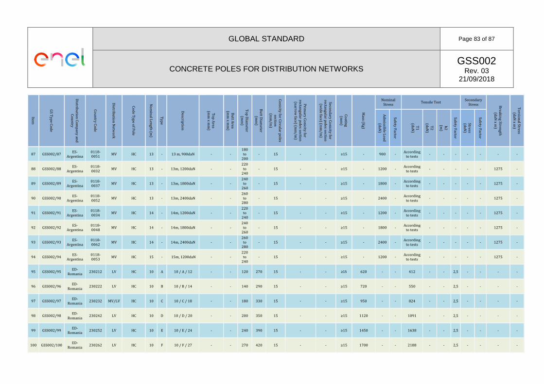
GLOBAL STANDARD Page 83 of 87
CONCRETE POLES FOR DISTRIBUTION NETWORKS GSS002
Rev. 03 21/09/2018
Item
GS T
ype C
od
e
Distrib
utio
n C
om
pan
y an
d
Co
un
try
Co
un
try Co
de
Distrib
utio
n N
etwo
rk
Co
de T
ype o
f Po
le
No
min
al Len
gth
(m)
Typ
e
Descrip
tion
To
p A
rea (m
m x m
m)
Bu
tt Area
(mm
x mm
)
To
p D
iameter
(mm
)
Bu
tt Diam
eter (m
m)
Co
nicity fo
r Circu
lar po
les sectio
n
(mm
/m)
Prim
ary Co
nicity fo
r rectan
gu
lar po
les section
(n
arrow
face) (mm
/m)
Secon
dary C
on
icity for
rectangu
lar po
les section
(w
ide face) (m
m/m
)
Co
ating
(m
m)
Mass (K
g)
Nominal Stress
Tensile Test Secondary
Stress Break
ing Stren
gth
(d
aN x m
)
To
rsion
al Stress (d
aN x m
)
Ad
missib
le Lo
ad
(daN
)
Safety F
actor
T1
(d
aN)
T2
(d
aN)
h2
(m
)
Safety F
actor
Stress (d
aN)
Safety F
actor
87 GSS002/87 ES-
Argentina 0118-0051
MV HC 13 - 13 m, 900daN - - 180 to
200 - 15 - - ≥15 - 900 -
According to tests
- - - - - - -
88 GSS002/88 ES-
Argentina 0118-0032
MV HC 13 - 13m, 1200daN - - 220 to
240 - 15 - - ≥15 - 1200 -
According to tests
- - - - - 1275 -
89 GSS002/89 ES-
Argentina 0118-0037
MV HC 13 - 13m, 1800daN - - 240 to
260 - 15 - - ≥15 - 1800 -
According to tests
- - - - - 1275 -
90 GSS002/90 ES-
Argentina 0118-0052
MV HC 13 - 13m, 2400daN - - 260 to
280 - 15 - - ≥15 - 2400 -
According to tests
- - - - - 1275 -
91 GSS002/91 ES-
Argentina 0118-0034
MV HC 14 - 14m, 1200daN - - 220 to
240 - 15 - - ≥15 - 1200 -
According to tests
- - - - - 1275 -
92 GSS002/92 ES-
Argentina 0118-0048
MV HC 14 - 14m, 1800daN - - 240 to
260 - 15 - - ≥15 - 1800 -
According to tests
- - - - - 1275 -
93 GSS002/93 ES-
Argentina 0118-0062
MV HC 14 - 14m, 2400daN - - 260 to
280 - 15 - - ≥15 - 2400 -
According to tests
- - - - - 1275 -
94 GSS002/94 ES-
Argentina 0118-0053
MV HC 15 - 15m, 1200daN - - 220 to
240 - 15 - - ≥15 - 1200 -
According to tests
- - - - - 1275 -
95 GSS002/95 ED-
Romania 230212 LV HC 10 A 10 / A / 12 - - 120 270 15 - - ≥15 620 - - 412 - - 2,5 - - - -
96 GSS002/96 ED-
Romania 230222 LV HC 10 B 10 / B / 14 - - 140 290 15 - - ≥15 720 - - 550 - - 2,5 - - - -
97 GSS002/97 ED-
Romania 230232 MV/LV HC 10 C 10 / C / 18 - - 180 330 15 - - ≥15 950 - - 824 - - 2,5 - - - -
98 GSS002/98 ED-
Romania 230242 LV HC 10 D 10 / D / 20 - - 200 350 15 - - ≥15 1120 - - 1091 - - 2,5 - - - -
99 GSS002/99 ED-
Romania 230252 LV HC 10 E 10 / E / 24 - - 240 390 15 - - ≥15 1450 - - 1638 - - 2,5 - - - -
100 GSS002/100 ED-
Romania 230262 LV HC 10 F 10 / F / 27 - - 270 420 15 - - ≥15 1700 - - 2188 - - 2,5 - - - -

GLOBAL STANDARD Page 84 of 87
CONCRETE POLES FOR DISTRIBUTION NETWORKS GSS002
Rev. 03 21/09/2018
Item
GS T
ype C
od
e
Distrib
utio
n C
om
pan
y an
d
Co
un
try
Co
un
try Co
de
Distrib
utio
n N
etwo
rk
Co
de T
ype o
f Po
le
No
min
al Len
gth
(m)
Typ
e
Descrip
tion
To
p A
rea (m
m x m
m)
Bu
tt Area
(mm
x mm
)
To
p D
iameter
(mm
)
Bu
tt Diam
eter (m
m)
Co
nicity fo
r Circu
lar po
les sectio
n
(mm
/m)
Prim
ary Co
nicity fo
r rectan
gu
lar po
les section
(n
arrow
face) (mm
/m)
Secon
dary C
on
icity for
rectangu
lar po
les section
(w
ide face) (m
m/m
)
Co
ating
(m
m)
Mass (K
g)
Nominal Stress
Tensile Test Secondary
Stress Break
ing Stren
gth
(d
aN x m
)
To
rsion
al Stress (d
aN x m
)
Ad
missib
le Lo
ad
(daN
)
Safety F
actor
T1
(d
aN)
T2
(d
aN)
h2
(m
)
Safety F
actor
Stress (d
aN)
Safety F
actor
101 GSS002/101 ED-
Romania 230272 LV HC 10 G 10 / G / 31 - - 310 460 15 - - ≥15 2100 - - 3286 - - 2,5 - - - -
102 GSS002/102 ED-
Romania 230224 LV HC 12 B 12 / B / 14 - - 140 320 15 - - ≥15 1000 - - 550 227 9 2,5 - - - -
103 GSS002/103 ED-
Romania 230234
MV / LV
HC 12 C 12 / C / 18 - - 180 360 15 - - ≥15 1270 - - 824 265 9 2,5 - - - -
104 GSS002/104 ED-
Romania 230244
MV / LV
HC 12 D 12 / D / 20 - - 200 380 15 - - ≥15 1460 - - 1099 - - 2,5 - - - -
105 GSS002/105 ED-
Romania 230254
MV / LV
HC 12 E 12 / E / 24 - - 240 420 15 - - ≥15 1900 - - 1648 - - 2,5 - - - -
106 GSS002/106 ED-
Romania 230264
MV / LV
HC 12 F 12 / F / 27 - - 270 450 15 - - ≥15 2250 - - 2198 - - 2,5 - - - -
107 GSS002/107 ED-
Romania 230274
MV / LV
HC 12 G 12 / G / 31 - - 310 490 15 - - ≥15 2700 - - 3296 - - 2,5 - - - -
108 GSS002/108 ED-
Romania 230276
MV / LV
HC 12 H 12 / H / 32 - - 320 500 15 - - ≥15 3600 - - 6280 - - 2,5 - - - -
109 GSS002/109 ED-
Romania 230245
MV / LV
HC 14 D 14 / D / 20 - - 200 410 15 - - ≥15 1910 - - 1099 220 10,8 2,5 - - - -
110 GSS002/110 ED-
Romania 230255
MV / LV
HC 14 E 14 / E / 24 - - 240 450 15 - - ≥15 2400 - - 1648 402 10,8 2,5 - - - -
111 GSS002/111 ED-
Romania 230265
MV / LV
HC 14 F 14 / F / 27 - - 270 480 15 - - ≥15 2800 - - 2198 263 10,8 2,5 - - - -
112 GSS002/112 ED-
Romania 230275
MV / LV
HC 14 G 14 / G / 31 - - 310 520 15 - - ≥15 3400 - - 3296 485 10,8 2,5 - - - -
113 GSS002/113 ED-
Romania 228010 MV HC 10 G 10 / G / 31 - - 310 460 15 - - ≥15 2100 - - 3286 - - 2,5 - - - -
114 GSS002/114 RJ-Brasil 4664001 LV HV 9 B 9m/600daN 110 x 140 290 x 392
- - - 20 28 15 750 600 2 ‐ ‐ ‐ ‐ 300 2 1200/600 ‐

GLOBAL STANDARD Page 85 of 87
CONCRETE POLES FOR DISTRIBUTION NETWORKS GSS002
Rev. 03 21/09/2018
Item
GS T
ype C
od
e
Distrib
utio
n C
om
pan
y an
d
Co
un
try
Co
un
try Co
de
Distrib
utio
n N
etwo
rk
Co
de T
ype o
f Po
le
No
min
al Len
gth
(m)
Typ
e
Descrip
tion
To
p A
rea (m
m x m
m)
Bu
tt Area
(mm
x mm
)
To
p D
iameter
(mm
)
Bu
tt Diam
eter (m
m)
Co
nicity fo
r Circu
lar po
les sectio
n
(mm
/m)
Prim
ary Co
nicity fo
r rectan
gu
lar po
les section
(n
arrow
face) (mm
/m)
Secon
dary C
on
icity for
rectangu
lar po
les section
(w
ide face) (m
m/m
)
Co
ating
(m
m)
Mass (K
g)
Nominal Stress
Tensile Test Secondary
Stress Break
ing Stren
gth
(d
aN x m
)
To
rsion
al Stress (d
aN x m
)
Ad
missib
le Lo
ad
(daN
)
Safety F
actor
T1
(d
aN)
T2
(d
aN)
h2
(m
)
Safety F
actor
Stress (d
aN)
Safety F
actor
115 GSS002/115 RJ-Brasil 4664002 MV HV 11 B-1,5
11/1000daN 140 x 182 360 x 490
- - - 20 28 15 1330 1000 2 ‐ ‐ ‐ ‐ 500 2 2000/1000 ‐
116 GSS002/116 RJ-Brasil 4664003 MV HV 11 B-3,0
11/1500daN 170 x 224 390 x 532
- - - 20 28 15 1953 1500 2 ‐ ‐ ‐ ‐ 750 2 3000/1500 ‐
117 GSS002/117 RJ-Brasil 4664004 MV HV 12 B-1,5
12/1000daN 140 x 182 380
x 518 ‐ ‐ ‐ 20 28 15 1520 1000 2 ‐ ‐ ‐ ‐ 500 2 2000/1000 ‐
118 GSS002/118 RJ-Brasil 4664005 MV HV 12 B-4,5
12/2000daN 200 x 266 440 x 602
‐ ‐ ‐ 20 28 15 2000 2000 2 ‐ ‐ ‐ ‐ 1000 2 4000/2000 ‐
119 GSS002/119 RJ-Brasil 6803414 MV HV 13 B 13/600daN 110 x 140 370 x 504
‐ ‐ ‐ 20 28 15 1400 600 2 ‐ ‐ ‐ ‐ 300 2 1200/600 ‐
120 GSS002/120 RJ-Brasil 4664006 MV HV 13 B-1,5
13/1000daN 140 x 182 400 x 546
‐ ‐ ‐ 20 28 15 2030 1000 2 ‐ ‐ ‐ ‐ 500 2 2000/1000 ‐
121 GSS002/121 RJ-Brasil 4664007 MV HV 13 B-4,5
13/2000daN 200 x 266 460 x 630
‐ ‐ ‐ 20 28 15 3090 2000 2 ‐ ‐ ‐ ‐ 1000 2 4000/2000 ‐
122 GSS002/124 GO -
Brazil 4284 MV HV 10 B 10/300 daN 110 x 140
310 x 420
- - - 20 28 ≥15 900 300 2 - - - - 150 2 600/300 ‐
125 GSS002/125 GO -
Brazil 14812 MV HV 10 B 10/600 daN 110 x 140
310 x 420
- - - 20 28 ≥15 900 600 2 - - - - 300 2 1200/600 ‐
126 GSS002/126 GO -
Brazil 519 MV HV 11 B 11/300 daN 110 x 140
330 x 448
- - - 20 28 ≥15 1050 300 2 - - - - 150 2 600/300 ‐
127 GSS002/127 GO -
Brazil 4288 MV HV 12 B 12/300 daN 110 x 140
350 x 476
- - - 20 28 ≥15 1210 300 2 - - - - 150 2 600/300 ‐
128 GSS002/128 GO -
Brazil 14805 LV HCV 9
C-17
9/300 daN - - 170 350 20 - - ≥15 820 300 2 ‐ ‐ ‐ ‐ ‐ ‐ 600 ‐
129 GSS002/129 GO -
Brazil 18727 LV HCV 9
C-19
9/600 daN - - 190 370 20 - - ≥15 1000 600 2 ‐ ‐ ‐ ‐ ‐ ‐ 1200 ‐
130 GSS002/130 GO -
Brazil 14811 MV HCV 10
C-23
10/1000 daN - - 230 430 20 - - ≥15 1350 1000 2 ‐ ‐ ‐ ‐ ‐ ‐ 2000 ‐

GLOBAL STANDARD Page 86 of 87
CONCRETE POLES FOR DISTRIBUTION NETWORKS GSS002
Rev. 03 21/09/2018
Item
GS T
ype C
od
e
Distrib
utio
n C
om
pan
y an
d
Co
un
try
Co
un
try Co
de
Distrib
utio
n N
etwo
rk
Co
de T
ype o
f Po
le
No
min
al Len
gth
(m)
Typ
e
Descrip
tion
To
p A
rea (m
m x m
m)
Bu
tt Area
(mm
x mm
)
To
p D
iameter
(mm
)
Bu
tt Diam
eter (m
m)
Co
nicity fo
r Circu
lar po
les sectio
n
(mm
/m)
Prim
ary Co
nicity fo
r rectan
gu
lar po
les section
(n
arrow
face) (mm
/m)
Secon
dary C
on
icity for
rectangu
lar po
les section
(w
ide face) (m
m/m
)
Co
ating
(m
m)
Mass (K
g)
Nominal Stress
Tensile Test Secondary
Stress Break
ing Stren
gth
(d
aN x m
)
To
rsion
al Stress (d
aN x m
)
Ad
missib
le Lo
ad
(daN
)
Safety F
actor
T1
(d
aN)
T2
(d
aN)
h2
(m
)
Safety F
actor
Stress (d
aN)
Safety F
actor
131 GSS002/131 GO -
Brazil 496 MV HCV 11
C-19
11/600 daN - - 190 410 20 - - ≥15 1260 600 2 ‐ ‐ ‐ ‐ ‐ ‐ 1200 ‐
132 GSS002/132 GO -
Brazil 4279 MV HCV 11
C-23
11/1000 daN - - 230 450 20 - - ≥15 1600 1000 2 - - - - ‐ ‐ 2000 ‐
133 GSS002/133 GO -
Brazil 41030 MV HCV 11
C-29
11/1500 daN - - 290 510 20 - - ≥15 2100 1500 2 - - - - ‐ ‐ 3000 ‐
134 GSS002/134 GO -
Brazil 500 MV HCV 12
C-19
12/600 daN - - 190 430 20 - - ≥15 1440 600 2 - - - - ‐ ‐ 1200 ‐
135 GSS002/135 GO -
Brazil 502 MV HCV 12
C-23
12/1000 daN - - 230 470 20 - - ≥15 1770 1000 2 - - - - ‐ ‐ 2000 ‐
136 GSS002/136 GO -
Brazil 5901 MV HCV 12
C-29
12/1500 daN - - 290 530 20 - - ≥15 2450 1500 2 ‐ ‐ ‐ ‐ ‐ ‐ 3000 ‐
137 GSS002/137 GO -
Brazil 3097 MV HCV 12
C-33
12/2000 daN - 330 570 20 - - ≥15 3000 2000 2 ‐ ‐ ‐ ‐ ‐ ‐ 4000 ‐
138 GSS002/138 GO -
Brazil 18728 MV HCV 13
C-17
13/300 daN - - 170 430 20 - - ≥15 1280 300 2 ‐ ‐ ‐ ‐ ‐ ‐ 600 ‐
139 GSS002/139 GO -
Brazil 4282 MV HCV 13
C-19
13/600 daN - - 190 450 20 - - ≥15 1680 600 2 ‐ ‐ ‐ ‐ ‐ ‐ 1200 ‐
140 GSS002/140 GO -
Brazil 504 MV HCV 13
C-23
13/1000 daN - - 230 490 20 - - ≥15 1920 1000 2 - - - - ‐ ‐ 2000 ‐
141 GSS002/141 GO -
Brazil 21016 MV HCV 13
C-29
13/1500 daN - - 290 550 20 - - ≥15 2700 1500 2 ‐ ‐ ‐ ‐ ‐ ‐ 3000 ‐
142 GSS002/142 GO -
Brazil 38243 MV HCV 13
C-33
13/2000 daN - - 330 590 20 - - ≥15 3500 2000 2 - - - - ‐ ‐ 4000 ‐
143 GSS002/143 GO -
Brazil 2815 MV HCV 14
C-19
14/600 daN - - 190 470 20 - - ≥15 1900 600 2 ‐ ‐ ‐ ‐ ‐ ‐ 1200 ‐
144 GSS002/144 CD-
Colombia 6762470 MV HC/HCV 12 - 12 X 2000 260 440 15 20 - 785 2,5 1961 -

GLOBAL STANDARD Page 87 of 87
CONCRETE POLES FOR DISTRIBUTION NETWORKS GSS002
Rev. 03 21/09/2018
Item
GS T
ype C
od
e
Distrib
utio
n C
om
pan
y an
d
Co
un
try
Co
un
try Co
de
Distrib
utio
n N
etwo
rk
Co
de T
ype o
f Po
le
No
min
al Len
gth
(m)
Typ
e
Descrip
tion
To
p A
rea (m
m x m
m)
Bu
tt Area
(mm
x mm
)
To
p D
iameter
(mm
)
Bu
tt Diam
eter (m
m)
Co
nicity fo
r Circu
lar po
les sectio
n
(mm
/m)
Prim
ary Co
nicity fo
r rectan
gu
lar po
les section
(n
arrow
face) (mm
/m)
Secon
dary C
on
icity for
rectangu
lar po
les section
(w
ide face) (m
m/m
)
Co
ating
(m
m)
Mass (K
g)
Nominal Stress
Tensile Test Secondary
Stress Break
ing Stren
gth
(d
aN x m
)
To
rsion
al Stress (d
aN x m
)
Ad
missib
le Lo
ad
(daN
)
Safety F
actor
T1
(d
aN)
T2
(d
aN)
h2
(m
)
Safety F
actor
Stress (d
aN)
Safety F
actor
145 GSS002/145 CD-
Colombia 6764017 MV
HC/HCV 12 - 12 X 2500 280 460 15 20 - 981 2,5 2452 -
146 GSS002/146 CD-
Colombia 6762455 MV
HC/HCV 12 - 12 X 3000 300 480 15 20 - 1177 2,5 2942 -
147 GSS002/147 CD-
Colombia 6763233 MV
HC/HCV 12 - 12 X 3500 320 500 15 20 - 1373 2,5 3432 -
148 GSS002/148 CD-
Colombia 6764099 MV
HC/HCV 14 - 14 X 2000 260 470 15 20 - 785 2,5 1961 -
149 GSS002/149 CD-
Colombia 6796158 MV
HC/HCV 14 - 14 X 2500 280 490 15 20 - 981 2,5 2452 -
150 GSS002/150 CD-
Colombia 6764021 MV
HC/HCV 14 - 14 X 3000 300 510 15 20 - 1177 2,5 2942 -
151 GSS002/151 CD-
Colombia 6764022 MV
HC/HCV 14 - 14 X 3500 320 530 15 20 - 1373 2,5 3432 -
152 GSS002/152 CD-
Colombia 6769870 MV
HC/HCV 12 - 12 X 1350 220 400 15 20 - 530 2,5 1324 -