Embed Size (px)
Citation preview

Tailor Made Concrete Structures – Walraven & Stoelhorst (eds)© 2008 Taylor & Francis Group, London, ISBN 978-0-415-47535-8
Concrete in the optimal network arch
Per TveitAgder University, Grimstad, Norway
ABSTRACT: The network arch is an arch bridge with inclined hangers that cross each other at least twice. Ifhangers cross each other only once, it is a Nielsen bridge. When the ties are a thin concrete slab, the networkarch uses less than 2/3 of the steel needed for arch bridges with vertical hangers. A network arch is likely toremain the world’s most slender arch bridge. The arches can be made from universal columns of American wideflange beams that come from the steel works with the desired curvature. In many equal spans in long bridges thearches can be made from high strength concrete. Network arches have a pleasing appearance and do not blockthe view to the landscape and cityscape behind them. A temporary tie can be used in the erection. Spans of upto 300 m can be finished on shore and be lifted onto the pillars by big floating cranes.
1 INTRODUCTION
The Bolstadstraumen Bridge in fig. 1 has a span of84 m. It was finished in 1963. p. 7 and 8. This is shortfor page 7 and 8 in (Tveit 2007), which can be foundon the internet. It is much simpler to find somethingon the internet than getting out a usual reference froma library. In fig. 1 you can see the electricity line butnot the hangers. That is because of the way the sun isshining.
If we define the slenderness of an arch bridge as thespan divided by the sum of the height of the chords,the Bolstadstraumen Bridge has been the world’s mostslender arch bridge for 44 years. It needed 44 t of struc-tural steel and 7 t of prestressing steel. The rise of thearch was 18% of the span.
Figure 1. Bolstadstraumen bridge is the world’s most slen-der arch bridge.
A competing arch bridge with vertical hangers anda rise in the arch of 21.5% of the span needed 2.5 timesmore structural steel. Both bridges had a concrete slabspanning between the arches. With transverse beams inthe tie the competing bridge would have needed morestructural steel.
The influence lines and the geometry of the Bol-stadstraumen Bridge can be found on p. 59.
2 BEAM ANALOGY
A network arch can be seen as a simply supportedbeam. The arch is the compression zone, and the tie isthe tension zone. The hangers are the web. Most of theshear force is taken by the vertical component of thecompressive force in the arch.
The force in the chords can be reduced by increasingthe distance between them, but aesthetic considera-tions limit the rise of the arch.
In network arches some mainly axial forces cannot be avoided. The optimal network arch takesthese forces as efficiently as possible. The optimal
Figure 2. Skeleton lines for two network arches spanning200 m. p. 8. (Tveit 1980).
743

network arch is an efficient structure for the followingreasons:
The details are simple, light and highly repetitive.Tension is predominant in the hangers and in the tie.There is little bending in the chords.
The compression in the arch is only around 3%greater than the tensile force in the tie. Arch and tie areclosely connected by the hangers. Thus the arch cantake a big buckling stress.All members make good useof high strength steels.
The arches can be made from universal columns orAmerican wide flange beams that come pre-bent fromthe steel works. Since the arch only has compression,butt joints can be used. p. 12.
The hangers distribute the loads between the chordsin such a way that there is very little bending in thechords, as long as all, or all but a few hangers are intension. P. 39, 57 and 58. The hanger arrangement tothe right in fig. 2 has a higher resistance to relaxationof hangers than the arrangement on the left.
Network arches are equally well suited for railand road bridges. Where a steel tie is used in rail-way bridges, about 30% of the steel has been saved
Figure 3. Necessary thickness of a concrete slab lane. (Teichand Wendelin 2001).
Figure 4. The Åkviksound network arch designed in by (Teich and Wendelin 2001).
compared to arch bridges with vertical hangers. p. 35.If a concrete tie is used, around twice as much steelcan be saved. p. 8, 31 and 93.
Where the tie is a concrete slab, the biggest bendingstress can be found halfway between the two arches.p. 14. Thus we do not need a big longitudinal beam inthe tie. We just need an edge beam for the prestressingcables, which must be strong enough to take the forcesfrom the hangers. The prestressing cables between theends of the arches shall be placed in the middle of theedge beam.
Figure 3. gives the necessary thickness of a concreteslab between arches. Higher concrete strength couldgive an even thinner slab. For slabs spanning over 10 mtransverse prestressing should be considered. Shouldtoo big deflections occur, they could be counteractedby spanning fiber reinforced polymer strands underthe slab.
3 AN OPTIMAL NETWORK ARCH
The bridge in fig. 4 is a bridge between two islandsin northern Norway. The footpaths are placed outsidethe arches to reduce the bending in the concrete slabbetween the arches. The footpaths must have room forthe machines that remove the snow.
The traffic is so little that we do not have to worryabout fatigue in the hangers. Otherwise the bridgeis designed according to the EU norms. The archesare universal columns that have been preshaped at thesteel mill.
Two ways of fastening the windbracing are shown.If a box section had been used, the details would havebeen much more complicated and the outer dimensionsof the arch would have been bigger.
744

In fig. 5 the steel weight per m2 of this network archis compared to steel weights of German arch bridgeswith vertical hangers.
N indicates that there is no windbracing. S indicatesthat the arches slope toward each other. The spans andthe year they were built are indicated.
The network arch tends to use less reinforcementin the tie than bridges that have steel beams under theconcrete slab. This is remarkable because the bridgeswith vertical hangers have transverse and longitudinalsteel beams in the tie. Furthermore the reinforcementin the network arch is less complicated.
Part of the reason for this is the high amount ofminimum reinforcement that is needed in the slab thatlies on top of the elongating longitudinal steel beams inthe tie.The longitudinal steel beams have high tension.Therefore the slab on top needs a lot of reinforcementto keep the cracks small.
In the optimal network arch the moderate longitudi-nal prestress in the serviceable limit state reduces theneed for minimum reinforcement.
If the network arch is narrow, most of the reinforce-ment is decided by the area around the concentratedload. Little extra reinforcement is needed to get theloads to the edge beams.
Transverse beams in the tie concentrate the load onthe edge beams. A slab gives a distributed load on theedge beams. Thus it leads to smaller bending momentsin the chords.
The network arch uses only 33% of the structuralsteel used in the Calbe Bridge and 23% of the structuralsteel used in the Jerusalem bridge in Magdeburg.
When in doubt, (Teich and Wendelin 2001) usu-ally adopted solutions that gave more steel. The steelweight in the Åkviksound network arch would havebeen smaller if it had the same rise in the arches as theother arch bridges in fig. 5.
As you all know, steel weight is not the only thingthat matters. Let us look at other differences betweenarch bridges with vertical hangers and network archesof the Åkvik type.
Bridges with vertical hangers are bulkier.They have2 to 8 times deeper chords. That gives less slender
Figure 5. Steel weight per m2 for various arch bridges.
spans and makes the ramps longer, and branching outroads at the ends of the bridge is more difficult.
Where vertical hangers are used, welds tend to be 15to 30 times longer. The details are more complicatedand there is 3 to 7 times as much surface to protect.
Other concrete parts need much more maintenancethan concrete slabs with a slight prestress. Erectionis less expensive with a half to a quarter of thesteel weight to erect. The light steel skeleton can beassembled on shore and be lifted into place. See later.
4 A METHOD OF ERECTION
The scaffolding for the network arch at Bolstadstrau-men is shown in fig. 4. It was erected on piles inthe sandy bottom of the river. After the concrete tiewas cast, the arch was erected. Then the hangers wereinstalled and tensioned till they carried the tie. Thenthe wooden scaffolding was removed.
Similar methods of erection can be used if thescaffolding would not be costly, for instance, for foot-bridges in towns and over rivers that have little waterhalf the year. In these cases bridges with shorter spanswould very often be more competitive.
5 TEMPORARY TIE
Figure 7 shows a temporary tie for the erection of net-work arches. Combined with arches and hangers it
Figure 6. Scaffolding of the Bolstadstraumen network arch.
745

makes a stiff steel skeleton that can be moved. Thistemporary tie needs no corrosion protection. It can beproduced on site, using high strength bolts.
This skeleton can be erected at one side of the riveror fjord and pulled over by cables from a tower on theopposite side.
This is very appropriate for spans over rivers withvery variable water levels, and in New Zealand whereMaori tradition forbids touching the river. The steelskeleton can carry the casting of the concrete tie. p. 29kto 30a and p. 50a to 50b.
First the concrete is cast around the curved parts ofthe prestressing cables. That is at the ends of the tie.After that, a slight prestress can reduce the stress inthe longitudinal beams in the tie. Then the edge beamsare cast from both ends to avoid relaxation of hangers.Then the concrete slab is cast.
The steel in the temporary chord can be reused inbridges of different network arches with various widthsand lengths. The plywood plates in the formwork canbe reused for many purposes.
The temporary tie should be considered in theunlikely event that the network arch needs to be takendown. The temporary tie could be put in place again.Then most of the concrete can be removed, beforethe remaining parts of the span are pulled over to theside-spans again.
6 REMOVAL OF TEMPORARY TIE
The removal of the temporary tie can be done using thewagon shown in fig. 8. p. 52 to 53a. The floor of the
Figure 7. Temporary tie for a network arch.
wagon has two extra long transverse beams that havebeen part of the temporary tie.
Four L-shaped beams with wheels on top have beenfastened to the transverse beams before the platformhas been lowered.The wagon can roll along the edge ofthe tie while the rest of the temporary tie is taken down.
7 THE SKODJE NETWORK ARCH
Figure 9 shows a suggestion for a network arch inSkodje in western Norway. p. 20 and 50a to 51. Veryfew ships will pass under the bridge so the low parts ofthe arch are allowed above the navigable parts of thefjord.
The parts of the arches that are under the lane can befloated in or erected from the side-spans.The structuralsteel above the lane, supplemented by a temporarylower chord, can be erected on side-spans. Then thissteel skeleton can be floated across the fjord by meansof a pontoon or a floating crane.
8 NETWORK ARCHES WITH CHORDS OFHIGH STRENGTH CONCRETE
Since concrete is good at taking compression, it wouldbe a suitable material for arches in network arches.Steel rods can be used in the hangers.
The forerunners of the network arch were theNielsen bridges. p. 54. (Nielsen 1929), (Nielsen 1932)Around 60 of these bridges was built between the twoworld wars. (Ostenfeld 76) Their arches were usu-ally made of concrete. Today that would give too highscaffolding costs. Next to none of the hangers of theNielsen bridges have broken in the roughly 70 yearssince they were built.
Figure 8. Joint in the temporary lower chord.
746
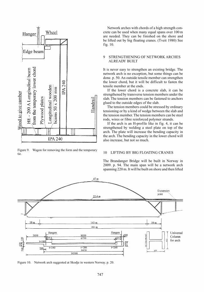
Figure 9. Wagon for removing the form and the temporarytie.
Figure 10. Network arch suggested at Skodje in western Norway. p. 20.
Network arches with chords of a high strength con-crete can be used when many equal spans over 100 mare needed. They can be finished on the shore andbe lifted out by big floating cranes. (Tveit 1980) Seefig. 10.
9 STRENGTHENING OF NETWORK ARCHESALREADY BUILT
It is never easy to strengthen an existing bridge. Thenetwork arch is no exception, but some things can bedone. p. 50. An outside tensile member can strengthenthe lower chord, but it will be difficult to fasten thetensile member at the ends.
If the lower chord is a concrete slab, it can bestrengthened by transverse tension members under theslab. The tension members can be fastened to anchorsglued to the outside edges of the slab.
The tension members could be stressed by ordinarytensioning or by a kind of wedge between the slab andthe tension member. The tension members can be steelrods, wires or fibre reinforced polymer strands.
If the arch is an H-profile like in fig. 4, it can bestrengthened by welding a steel plate on top of thearch. The plate will increase the bending capacity inthe arch. The bending capacity in the lower chord willalso increase, but not so much.
10 LIFTING BY BIG FLOATING CRANES
The Brandanger Bridge will be built in Norway in2009. p. 94. The main span will be a network archspanning 220 m. It will be built on shore and then lifted
747

Figure 11. Cross-section of concrete network arch.
to the pillars by two floating cranes lifting over 800tonnes each. It will be at least twice as slender as theBolstadstraumen Bridge. (Larsen and Aas- Jakobsen2006) and (Tveit 2006).
Floating cranes can lift up to 3000 tonnes. They canbe used for lifting finished spans over 300 m. Con-crete network arches with a cross-section like in fig. 9,spanning around 250 m, can be lifted in place beforethe slab under the railway is cast. p. 28.
11 WHY HAVE SO FEW NETWORKARCHES BEEN BUILT?
Network arches have been built in the Czech Republic,Germany, Norway and USA. It has been decided tobuild more network arches in all these countries. Theauthor has been wondering why so few network archeshave been built.
The introduction of the optimal network arch wouldgive extra work for bridge designers, and there is ageneral shortage of engineers that can be trusted withthe design of a first network arch. Everybody has a lotof intriguing problems that they would rather study. Inmany cases the excuses for not using network archesare not valid.
Steel firms have little interest in bridges that needso little steel. The concrete firms would like to seemore concrete. They do not favour having to cooperateclosely.
The introduction of the optimal network arch wouldgive extra work for bridge authorities. However, theauthor hopes that they will find the time and thecourage to promote network arches. General conser-vatism might be the main reason why this promisingtype of bridge is not built.
12 CONCLUSION
Network arches need little materials. In network archeswith less than 15 m between the arches, the tie can be
a thin concrete slab. Compared to arch bridges withvertical hangers and steel beams in the tie, an optimalnetwork arch normally saves over two thirds of thestructural steel. Still both alternatives use nearly thesame amount of reinforcement.
Optimal network arches can be very slim, whichgives a pleasing appearance. In bridges where manyequal spans are needed, the arches can be made fromconcrete. Spans up to 300 m can be finished on shoreand floated to the pillars.
To some civil engineers the author’s claims mayseem exaggerated, but it would be stupid to exaggeratewhen the bare facts seems like an exaggeration.
Most of the network arches that have been builthave permanent steel beams in the ties. The authorappeals to all members of fib. Do not let the steelpeople highjack the network arch.
REFERENCES
Herzog, Max. (1975). “Stahlgewichte moderner Eisenbahn-und Straβenbrücken.” (Steel Weights of Modern Rail- andRoad-bridges.) Der Stahlbau 9/1975.
Larsen, R. L. and Aas-Jakobsen, K. (2006) “Brandanger-sundet Bru – Verdens slankeste?” “BrandangersundetBridge – The World’s Most Slender?” (In Norwegian).Stålbygnad, Stockholm, 2006. No. 2. p. 37–38. ISSN1404–9414.
Nielsen, O. F. (1929) “Foranderlige Systemer med anvendelsepå buer med skraatstillede Hængestenger.” “Discontinu-ous systems used on arches with inclined hangers”, (inDanish.) 121 pages. Gad Copenhagen. Ph.D. thesis.
Nielsen, O. F. (1932) “Bogenträger mit Schräg gesteltenHängestangen.” (“Arches with inclined hangers,” in Ger-man.) Internationale Vereiningung f. Brückenbau undHochbau. Abhandlungen 1, 1932. pp. 355–363.
Teich, S. and Wendelin, S. (2001) “Vergleichsrech-nung einer Netzwerkbogenbrücke unter Einsats desEuropäishen Normenkonsepts.” (In German). Gradua-tion thesis at TU-Dresden. August 2001. 300 pages.A revised version of this thesis can be found athttp://fag.grm.hia.no/fagstoff/ptveit/
Tveit, P. (1980) “Network Arches.” 11th IABSE Congress,held in Vienna, Austria, Final Report, IABSE,ETH-Hönggerberg, CH-8039, Zürich, Switzerland,pp. 817–818.
Tveit, P. (2006). “Nettverkbroer, en effektiv kombinasjon avstål og betong” “Network arches, an efficient combina-tion of steel and concrete.” (In Norwegian). Stålbygnad,Stockholm, 2006. No. 2. p. 33–35. ISSN 1404–9414.
Tveit, P. (2007) “The Network Arch. Bits of Manuscript afterLectures in 44 Countries” 140 pages. http://pchome.grm.hia.no/∼pchome/ This home page will be updated atirregular intervals. Consequently some of the page num-bers given in this edition might not be quite correct in thefuture.
748