Embed Size (px)
Citation preview

SHRP-H-349
Concrete Pavement RepairManuals of Practice
J ?...
• !"..
_'. *o
. . , ~ . - _ ... ...
,.+ ...... • ..... . ... _ 4+" • .
j_/t_.- ........ •............................... J .....
Materials and Procedures for the Repairof Joint Seals in Concrete Pavements
Lynn D. Evans, A. Russell Romine
Materials and Proceduresfor Rapid Repair ofPartial-Depth Spalls in Concrete PavementsArti J. Patel, Cynthia A. Good Mojab, A. Russell Romine
ERES Consultants, Inc., Savoy, Illinois
Strategic Highway Research ProgramNational Research Council
SHRP-H-349
ISBN 0-309-05608-X
Contract H-106
Product no. 3003
Program Manager: Don M. Harriott
Project Manager: Shashikant C. Shah
Program Area Secretary: Francine A. Burgess
August 1993
Reprinted September 1994
key words:bituminous
cementitious
inspection
joint resealing
patching
pavement maintenance
polymerportland cement concretesealant
spall repair
Strategic Highway Research ProgramNational Research Council
2101 Constitution Avenue N.W.
Washington, DC 20418
(202) 334-3774
The publication of this report does not necessarily indicate approval or endorsement by the
National Academy of Sciences, the United States Government, or the American Association
of State Highway and Transportation Officials or its member states of the findings, opinions,
conclusions, or recommendations either inferred or specifically expressed herein.
©1993 National Academy of Sciences
1.5M/NAP/0893
IM/NAP/0994

Preface
This book contains two pavement maintenance manualsintended for use by highway maintenance agencies andcontracted maintenance firms in the field and in the office.
Each is a compendium of good practices for portland cementconcrete (PCC) joint resealing and partial-depth spall repair,respectively, stemming from two Strategic HighwayResearch Program (SHRP) studies.
In project H-105, Innovative Materials and Equipment forPavement Surface Repair, the researchers conducted amassive literature review and a nationwide survey ofhighway agencies to identify potentially cost-effective repairand treatment options. The information and findings fromthis study were then used in the subsequent field experimentsconducted under project H-106, Innovative MaterialsDevelopment and Testing.
In the H-106 project, the installation and evaluation of manydifferent test sections were conducted to determine the cost-
effectiveness of maintenance materials and procedures. Testsections were installed at 22 sites throughout the UnitedStates and Canada between March 1991 and February 1992,under the supervision of SHRP representatives. Theresearchers collected installation and productivity informationat each site and periodically evaluated the experimentalrepairs and treatments for 18 months following installation.
Long-term performance and cost-effectiveness informationfor the various repair and treatment materials and procedureswas not available at the time these manuals were prepared.However, subsequent performance evaluations may lead tofuture editions of these manuals to address performance andcost-effectiveness more thoroughly.
111

For the reader's convenience, potentially unfamiliar termsare italicized at their first occurrence in the manuals and aredefined in glossaries. Readers who want more informationon topics included in the manuals should refer the referencelists for each manual. The final report for the H-106 projectmay be of particular interest to many readers. 2 It details theinstallation procedures, laboratory testing of the materials,and field performance of each of the repair and treatmenttypes.
iv
Acknowledgments
The research described herein was supported by the StrategicHighway Research Program (SHRP). SHRP is a unit of theNational Research Council that was authorized by Section128 of the Surface Transportation and Uniform RelocationAssistance Act of 1987.
Special thanks are due the project management team atSHRP, and to the following highway agencies.
Manual for joint repair:Arizona Department of TransportationColorado Department of TransportationIowa Department of TransportationKentucky Transportation CabinetSouth Carolina Department of Highways and PublicTransportation
Manual for spall repair:Arizona Department of TransportationCommonwealth of Pennsylvania Department ofTransportationSouth Carolina Department of Highways and PublicTransportationUtah Department of Transportation
The contributions of the following individuals are alsoacknowledged.
Manual for joint repair: David Peshkin, Michael Darter,Sam Carpenter, Michael Belangie, Henry Bankie, JimChehovits, and Jeff Randle.
Manual tbr spall repair: Michael Darter, Sam Carpenter,Leo Ferroni, and David Peshkin.

Materials and Proceduresfor the Repair of Joint Seals
in Concrete Pavements
Manual of Practice
.... :........:..::.:
::i::_:i:I:i::=:'_::/._:::_II.II_
//_I_I_,S__",//,,,2_:,,,,:_:,,,/:, , ,, ,, ,,, ,, ,,,,,,, ,: ,, ,,,,,,:,,,/ ,,:,,,,,,,,
:==' ':::. ' .": ':i:_ _:"(=_:(:"_ ' ' • :: .:. = '::.:. %1 ._._.:::: ::.
i.:::::.:._i
':: . .. :.
Strategic Highway Research ProgramNational Research Council
Contents
Preface .. .................................. iii
Acknowledgments .......................... .... vi1.0 Introduction .............................. 1
1.1 Scope of Manual .................... 11.2 Overview ......................... 1
2.0 Need for Joint Resealing .................... 32.1 Seal Condition ...................... 32.2 Pavement Condition .................. 92.3 Climatic Conditions ................. 112.4 Traffic Level ...................... 13
2.5 Determining the Need to Reseal ........ 13
3.0 Planning and Design ..................... 153.1 Primary Considerations ............... 153.2 Objective for Resealing ...... ........ 153.3 Accounting for Existing Conditions ...... 163.4 Selecting a Sealant Material ........... 173.5 Selecting Backer Materials ............ 203.6 Selecting Primer Materials ............ 223.7 Selecting Joint Reservoir Dimensions .... 223.8 Selecting Preparation and
Installation Procedures ............... 26
3.9 Selecting Equipment ................ 283.9.1 Joint Plow .................. 303.9.2 Concrete Saw ............... 32
3.9.3 Abrasive Blasting Equipment ..... 333.9.4 Airblasting Equipment ......... 353.9.5 Hot Airblasting Equipment ...... 363.9.6 Backer-Rod Installation Tools .... 36
3.9.7 Hot-Applied Sealant InstallationEquipment .................. 37
3.9.8 Silicone Sealant Applicators ..... 383.9.9 Other Equipment ............. 39
vii

3.10 Estimating Material, Labor,and Equipment Requirements .......... 39
3.11 Determining Cost-Effectiveness ......... 413.11.1 Material and Shipping Costs ..... 423.11.2 Labor Costs ................. 42
3.11.3 Equipment Costs ............. 433.11.4 User Delay Costs ............. 433.11.5 Cost-Effectiveness Comparisons . .. 43
4.0 Construction ........................... 474.1 Traffic Control .................... 47
4.2 Safety Precautions .................. 474.3 Preparing the Joints ................. 48
4.3.1 Removing the Old Sealant ....... 484.3.2 Refacing the Joint Sidewalls ..... 514.3.3 Abrasive Blasting the
Joint Sidewalls ............... 53
4.3.4 Airblasting the Joint Reservoir .... 564.3.5 Installing Primer ............. 59
4.4 Material Preparation and Installation ..... 594.4.1 Installing Backer Rod .......... 604.4.2 Sealant Installation ............ 63
4.4.2.1 Hot-Applied Sealant ..... 64Heating the Sealant ...... 64Methods for Installation... 66
Cleanup Requirements .... 69Safety Precautions ...... 70
4.4.2.2 Cold-Applied Sealant . .. 70Loading Sealant into thePumping Apparatus ...... 71Methods for Installation... 71
Cleanup Requirements .... 74
5.0 Evaluation of Joint Seal Performance .......... 75
°,°VIII
Appendix A Material Testing Specifications ......... 77Appendix B Sample Cost-Effectiveness Calculations ... 81Appendix C Material and Equipment Safety Precautions 87Appendix D Inspection Checklists for Construction .... 89Appendix E Partial List of Material and
Equipment Sources ................. 103
Glossary .................................. 107References ................................ 111
ix

Figures
Figure 1. Pavement survey form ................ 4
Figure 2. Sealant adhesion failure ............... 7
Figure 3. Full-depth spall distress ............... 9
Figure 4. Typical joint cross-section ............ 23
Figure 5. Rear-mounted joint plow ............. 30
Figure 6. Belly-mounted joint plow ............. 31
Figure 7. Concrete joint saw .................. 32
Figure 8. Abrasive blasting equipment ........... 34
Figure 9. Air compressor .................... 35
Figure 10. Automated backer-rod installation tool .... 37
Figure 11. Joint plowing operation .............. 50
Figure 12. Joint sawing operation ............... 52
Figure 13. Abrasive blasting operation ............ 55
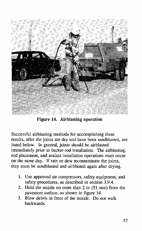
Figure 14. Airblasting operation ................ 57
Figure 15. Backer-rod installation ............... 62
Figure 16. Hot-applied sealant installation ......... 67
Figure 17. Silicone sealant installation ............ 72
Figure 18. Example joint seal deterioration chart ..... 76
xi
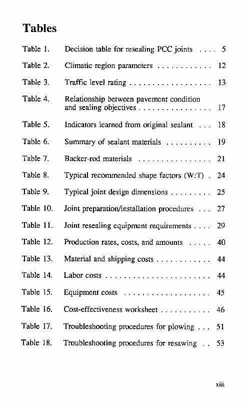
Tables
Table 1. Decision table for resealing PCC joints .... 5
Table 2. Climatic region parameters ............ 12
Table 3. Traffic level rating .................. 13
Table 4. Relationship between pavement conditionand sealing objectives ................ 17
Table 5. Indicators learned from original sealant . .. 18
Table 6. Summary of sealant materials .......... 19
Table 7. Backer-rod materials ................ 21
Table 8. Typical recommended shape factors (W:T) . 24
Table 9. Typical joint design dimensions ......... 25
Table 10. Joint preparation/installation procedures . . . 27
Table 11. Joint resealing equipment requirements .... 29
Table 12. Production rates, costs, and amounts ..... 40
Table 13. Material and shipping costs ............ 44
Table 14. Labor costs ....................... 44
Table 15. Equipment costs ................... 45
Table 16. Cost-effectiveness worksheet ........... 46
Table 17. Troubleshooting procedures for plowing . .. 51
Table 18. Troubleshooting procedures for resawing . . 53
xiii

Table 19. Troubleshooting procedures forsandblasting ...................... 56
Table 20. Troubleshooting procedures forairblasting ........................ 58
Table 21. Troubleshooting procedures forbacker-rod installation ............... 63
Table 22. Troubleshooting procedures forhot-applied sealant installation ........ 68-69
Table 23. Troubleshooting procedures forcold-applied sealant installation ....... 73-74
Table A-1. Rubberized asphalt specifications ........ 78
Table A-2. Nonsag silicone sealant specifications .... 79
Table A-3. Self-leveling silicone sealant specification.. 80
Table B-1. Example material and shipping costs ..... 82
Table B-2. Example labor costs ................. 83
Table B-3. Example equipment costs ............. 84
Table B-4. Example cost-effectiveness calculations . .. 85
xiv

1.0 Introduction
This manual has been prepared for use by maintenanceengineers, maintenance field supervisors, crew persons,maintenance contractors, and inspectors as an easy referencefor resealing* transverse and longitudinal joints in portlandcement concrete (PCC) pavements.
1.1 Scope of Manual
Included in this manual are descriptions of procedures andmaterials recommended for resealing joints in PCCpavements. Guidelines for planning a resealing project aswell as steps for installing joint seals and inspecting theprocess are presented. The resealing of concrete-asphaltshoulder joints or sealing cracks in PCC pavements is notaddressed. The information contained in this manual is
based on the most recent research, obtained through reviewsof literature and of current practice as well as from the fieldresults of an ongoing study. 1'2 This study investigates theperformance in PCC joints of various hot- and cold-appliedsealants using several methods of installation.
1.2 Overview
Several steps are required for successful resealing of joints inPCC pavements. The first is determining the need forresealing the joints. Chapter 2 contains a general procedurefor deciding whether to reseal. This procedure can be easilymodified to meet the needs of each highway agency.
Italicizedwordsaxedefinedin the glossary.

Once the need for resealing is determined, the next step isplanning the operation. Chapter 3 leads the maintenanceplanner through the steps for selecting sealant and accessorymaterials, choosing preparation and installation procedures,specifying equipment, and estimating material and laborrequirements.
The construction phase of joint resealing is described inchapter 4. Details of each step of the preparation andinstallation operations are listed along with troubleshootingprocedures for each operation.
In addition, the appendices provide material testingspecifications, sample cost-effectiveness calculations, safetyprecautions, and inspection checklists to help ensure goodresealing practices and high-quality results.
2

2.0 Need for Joint Resealing
Excessive delay in replacing a failing sealant system inconcrete pavement joints can result in more rapiddeterioration of the pavement. However, if sealant isreplaced too early, precious maintenance funds may not havebeen used in the most cost-effective manner. How, then, can
those responsible for maintenance determine when is the besttime to reseal joints in concrete pavements? Some statesspecify that joints be resealed when a specified amount ofsealant material (25 to 50 percent) has failed, allowingmoisture and/or incompressible materials to progress past thesealant to the underlying layers. Other agencies base theirdecision on pavement type, pavement and sealant condition,and available funding.
Another more complete method to determine whether or nota pavement needs to be resealed is to calculate ratingnumbers based on the sealant and pavement condition, trafficlevels, and climatic conditions. Figure 1 presents aworksheet that can be used to estimate these properties, andtable 1 gives the user recommendations about the need toreseal, based on these properties. The following sectionsassist in determining the necessary ratings and conditions.
2.1 Seal Condition
Joint-sealant system effectiveness is judged by the sealant'sability to resist embedment of incompressible materials andthe sealant system's success in preventing entry of water andincompressibles into the joint. To evaluate pavement sealcondition, the following steps should be completed andresults recorded on figure 1:

ISealant Condition Pavement Condition ° I
I
iiiiiiiiiiiiiii_iii_i_i_i_i_ii!i_i!iiiiiiiiiiiiiii_i_i_i_i_i_i_i_iiiiiiiii_ !_ _::i, ::?:_::_::?:?:!::_::i::!::i::i::i::i::i::i::i_i::i::i::i_::i_?:_i::_:_!::_i!::_::iiiiiiiiiiii::i::i::i::i::ii::i_i!!ii_i_
10 ::10-301 > 30 i i. ! Expected pavement _> 10 _5-10 1 < 5Water entering, % length <
_ _ . life, yrs _ _ .
-: _ i<0.06! 0.06- i>0.12I i I
Stone intrusion i Low _Med !High Avg. faulting, in_ _ _ 0.12
........................................ _......... ;......... _...........
Sealant Rating iGoodlFairiPoor Coraerbreal_,%slabs I <1! 1-5 i >5.. : : ........................................ _......... _......... _...........
Pumping, % joints i <1 i 1-5 i >5
Environmental Conditions ° Spans> 1 in, % slabs i <5 i 5-I0i >10
Avg. annual precip., in i Pavement rating !Good! Fair [ Poor
Days < 32°F (0°C) !
............................................z............................. Current Joint v.snes;-nAvg. low / high temp, °F !
WF WNFClimatic region • _ DF DNF Sealant age, yrs
Avg. sealant depth, in i
Traffic Conditions Avg. joint width, in
ADT (vpd); % Tracks i i Avg. joint depth, in........................................ 4 ..............................
Traffic level b i Low i Med iHigh Max. joint spacing, ft ::
Sce table 2.See table 3.
1 inch = 25.4 mm; 1 ft = 0.305 m
Figure 1. Pavement survey form

Table 1. Decision table for resealing PCC joints
Climatic Region
Sealant Pvmt. Traffic Freeze Nonfreeze
Rating Rating RatingWet :_ Dry Wet i Dry
Fair Good Low Possibly i Possibly Possibly i PossiblyJ I
.................. i .................. ° ........................................ ,_...................... ° ...................... : .....................
Fair Good Med Yes i Possibly Possibly i Possibly.................. i .................. ° ........................................ ,; ...................... ° ...................... _:.....................
Fair Good High Yes i Yes Yes i Possibly
iFair Fair Low Yes :_Possibly Possibly Possibly
Fair Fair Med Yes i Yes Yes i Possibly............................................................................. _............................................ ...al. ................
Fair Fair High Yes i Yes Yes i Possibly
Fair Poor Low Possibly i Possibly Possibly i PossiblyJ
.................. _ .................. . ......................................... ,; ...................... • ...................... : .....................
Fair Poor Med Yes i Yes Yes i Possibly
Fair Poor High Yes i Yes Yes i Yes
Poor Good Low Yes i Possibly Possibly i Possibly.................. 1.................. ! ......................................... ":...................... q...................... _......................
Poor Good Med Yes i Yes Yes i Possibly
Poor Good High Yes i Yes Yes i Yes
Poor Fair Low Yes i Yes Yes i Possibly
Poor Fair Med Yes i Yes Yes i Yes............................................................................ " ...................... o...................... _:......................
Poor Fair High Yes _ Yes Yes _ Yes
Poor Poor Low Yes i Yes Yes i Possibly.................. i .................. 4........................................ ,; ...................... i ...................... _......................
Poor Poor Med Yes i Yes Yes i Yes.................. I .................. i ........................................ .; ...................... i ...................... ; ......................
Poor Poor High Yes ! Yes Yes i Yes
a Sealants rated in "Good" condition do not require replacement.

• Choose 10 or more joints whose sealant condition isrepresentative of the entire site. If large variations incondition are evident, subdivide the site into sections
having similar seal condition and evaluate 5 to 10joints from each section.
• Cut 2-in (51-mm) samples of sealant from a fewjoints and measure the joint width, depth, and sealantthickness.
• Determine from the construction records the type and
age of the sealant and the design joint width andsealant thickness.
• Record the maximum spacing between joints.
Carefully inspect each of the 10 or more chosen joints,recording the following items on figure 1:
• Water resistance is the percent of overall joint lengthwhere water can bypass the sealant and enter thejoint.
• Stone intrusion is the amount of stones, sand, anddebris that is embedded in the sealant.
Loss of bonding to the concrete sidewall, shown in figure 2,full-depth spalls, shown in figure 3, and torn or missingsealant are common joint seal distresses. They reduce waterresistance and allow moisture, sand, and dirt to enter the
joint. Bond failure can be determined by pulling the sealantaway from the joint edge and inspecting for adhesion failure.Full-depth spalls can be identified by gently inserting a dullknife into the spall and observing whether the knife tip canpass below the sealant. Another method for locating areas ofbond failure is with a vacuum tester as developed by theIowa Department of Transportation. The percent of waterresistance loss can be computed using equation 1.
6

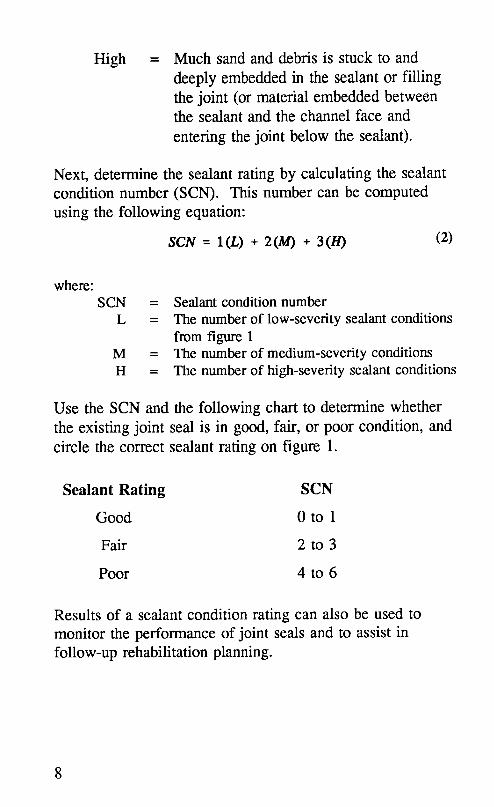
High = Much sand and debris is stuck to anddeeply embedded in the sealant or fillingthe joint (or material embedded betweenthe sealant and the channel face and
entering the joint below the sealant).
Next, determine the sealant rating by calculating the sealantcondition number (SCN). This number can be computedusing the following equation:
SCN = I(L) + 2(/14) + 3(/-/) (2)
where:SCN = Sealant condition number
L = The number of low-severity sealant conditionsfrom figure 1
M = The number of medium-severity conditionsH = The number of high-severity sealant conditions
Use the SCN and the following chart to determine whetherthe existing joint seal is in good, fair, or poor condition, andcircle the correct sealant rating on figure 1.
Sealant Rating SCN
Good 0 to 1
Fair 2 to 3
Poor 4 to 6
Results of a sealant condition rating can also be used tomonitor the performance of joint seals and to assist infollow-up rehabilitation planning.
8

Figure 3. Full-depth spall distress
2.2 Pavement Condition
A pavement will provide several indicators that the joint sealis not performing adequately and is allowing too much waterto reach the underlying layers. These indicators include:
• Surface staining or the accumulation of fine materialon the surface close to joints or cracks indicatespumping of the base or subbase. This results, in part,from excess moisture and it contributes to formation
9

of voids beneath the pavement, cracks, and comerbreaks.
• Faulting, or dropoff between adjacent slabs, possiblyindicates that excess moisture is reaching a water,susceptible base and/or subgrade, and that voids areforming beneath one side of the pavement as a resultof continual traffic.
• D-cracking of susceptible pavement can result fromexcess moisture beneath a pavement.
A pavement system can also manifest the effects of theentrance of stones and other incompressible materials intopavement joints by the following:
• Compression-related spalls are present of the walls ofjoints that are filled with sand and stones.
• Blowups have occurred and slab edges have shattered.There has been a permanent increase in joint widthcausing movement of nearby bridge supports.
To evaluate the condition of a pavement considered forresealing, record the following items in the pavementcondition section of figure 1. These items should be basedon field inspection and the maintenance schedule.
1. The estimated number of years before the pavementrequires major rehabilitation
2. The average vertical faulting movement3. The percent of slabs containing comer breaks4. The percent of joints visually indicating pumping5. The percent of slabs containing full-depth spalls
extending greater than 1 in (25.4 mm) or more fromthe face of the joint
10

To determine a pavement condition number (PCN), usefigure 1 and equation 3.
PCN = 1(L) + 2(M) + 3 C/-/) (3)
where:PCN = Pavement condition number
L = The number of low-severity pavementcondition indicators from figure 1
M = The number of medium-severity pavementcondition indicators
H = The number of high-severity pavementcondition indicators
Use the PCN and the following chart to determine whetherthe existing pavement is in good, fair, or poor condition, andcircle the correct pavement rating on figure 1:
Pavement Rating PCN
Good 0 to 3
Fair 4 to 5
Poor 6 to 15
2.3 Climatic Conditions
The effects of extreme temperatures and precipitation onjoint seal and pavement performance cannot be minimized.In extreme cold, sealants are stretched the most as pavementsshrink and joints widen. Extreme heat results in expandingslabs and shrinking joints. This can compress improperlyplaced sealant so that it is forced above the pavement surfaceand may be pulled out by passing traffic.
11

Wet climatic regions need highly effective seals, approaching100 percent effectiveness to prevent water damage to thebase and pavement structures. Similarly, dry climates alsorequire highly effective seals in order to prevent the intrusionof incompressible material into the joint, which can result injoint growth, blowups, and structural damage.
When evaluating the climatic conditions that a pavement willexperience, determine for that location the followinginformation and enter it in the environmental condition
section of figure 1:
• The normal annual total precipitation for the location• The mean number of days in a year with a minimum
temperature of 32°F (0°C) or below• The highest and lowest recorded temperatures
This information is available from the National Climatic Data
Center in Asheville, N.C., or from local weather recordingstations. Then, using the information on figure 1 and table 2,identify the climatic region in which the pavement is located.Circle the correct climatic region on figure 1.
Table 2. Climatic region parameters
Climatic MeanAnnualDays AverageAnnualRegion <_32°F(0"C) Precipitation
Wet-fieeze > 100 > 25 in (635 mm)
Wet-nonfreeze < 100 > 25 in (635 mm)
Dry-freeze > 100 < 25 in (635 mm)
Dry-nonfreeze < 100 < 25 in (635 mm)
12

2.4 Traffic Level
To identify traffic conditions, obtain the average daily traffic
(ADT) level in vehicles per day (vpd) and the percent truck
traffic. Determine the traffic level rating from table 3. If the
percent truck traffic is greater than 10 percent or the
expected growth rate is greater than 5 percent, borderlinetraffic level ratings should be increased one level.
Table 3. Traffic level rating
Traffic Level ADT, vpd all lanes
Low < 5,000
Medium 5,000 to 35,000
High > 35,000
2.5 Determining the Need to Reseal
After completing the pavement evaluation worksheet, use
table 1 and the calculated sealant rating (SCN), pavement
rating (PCN), the traffic rating, and the climatic region toevaluate the need for resealing. The table makesrecommendations about the need for resealing based on theratings of the evaluation worksheet. The basis for the table
is engineering experience; however, it can be adjusted to theneeds and policies of individual state agencies. Choose the
row with the combination of sealant, pavement, and trafficrating from the three left-hand columns that match the
pavement being evaluated. Then, find the intersection of that
row with the appropriate climatic region to obtain the
recommendation on the need for resealing.
13

If the recommendation is that sealing is "possibly" needed,then the case is borderline, and good judgment based on
experience should be used in determining the need to reseal.When an overlay or rehabilitation is scheduled within 3 to 5years, sealing could be delayed unless pavement or basedamage would result.
14

3.0 Planning and Design
3.1 Primary Considerations
After determining the need to reseal the joints in a concretepavement section, it is important to plan the sealing operationto ensure that a proper resealing job is completed. Properplanning should take into account these factors:
• The long- and short-term objectives for resealing• The current sealant and pavement condition and the
place of the resealing effort in an overall maintenanceplan
• The applicability and documented performance of thesealant materials chosen for use
• The effectiveness of the equipment and installationmethods chosen for use
• The level of strain placed on the sealant system as aresult of the dimensions of the joint reservoir
• The minimization of traffic disruption, increasedworker safety, and efficient installation rates
3.2 Objective for Resealing
When beginning, it is important to determine the objective ofthe resealing project. Possible objectives include:
• Temporarily sealing pavement joints for 1 to 2 yearsuntil the pavement is overlaid or replaced.
• Sealing and maintaining watertight joints for 3 to 5years.
• Sealing and maintaining watertight joints for a periodextending more than 5 years.
15

Each of these objectives may be correct for a differentsituation, depending primarily on the pavement condition andthe traffic level, as illustrated in table 4.
In dry climates, it is more important to keep sand and dirtout of the joints to prevent spalling and blowups. A sealantshould then be chosen that does not allow sand to penetratethe sealant surface. In hot climates, some sealants flow downinto the joint, or track on the surface, or allow stones tobecome embedded in the sealant. In some situations, a jet-fuel-resistant sealant material is required. In somepavements, only certain areas of sealant are failed, andselective replacement is needed. Consequently, whenchoosing sealant materials and installation methods, theobjectives must match the requirements of the situation.
3.3 Accounting for Existing Conditions
The condition of a pavement when it is resealed can greatlyaffect the performance of the seal. Comer breaks, largespalls, voids beneath the pavement, faulting, and poor loadtransfer can all reduce the effective life of resealed joints.Depending on existing conditions, some of these pavementdistresses should be repaired before sealant is installed. 3Specifically, prior to resealing, the following repairs shouldbe considered: 4
• Full-depth repair of corner breaks and deep spalls• Partial-depth repair of spalls that extend more than
1 in (25.4 mm) from the face of the joint• Improving subdrainage and/or roadside drainage• Restoring load transfer at joints and cracks where
poor load transfer exists• Undersealing the pavement where voids exist
16
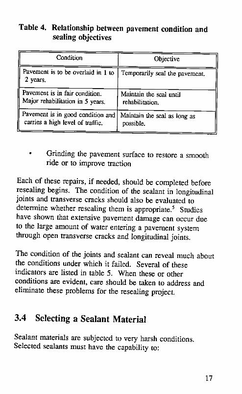
Table 4. Relationship between pavement condition andsealing objectives
Condition Objective
Pavementis to be overlaidin 1 to Temporarilysealthe pavement.2 years.
Pavementis in fair condition. Maintainthe seal untilMajorrehabilitationin 5 years, rehabilitation.
Pavementis in goodconditionand Maintainthe seal as long ascarries a high levelof traffic, possible.
• Grinding the pavement surface to restore a smoothride or to improve traction
Each of these repairs, if needed, should be completed beforeresealing begins. The condition of the sealant in longitudinaljoints and transverse cracks should also be evaluated todetermine whether resealing them is appropriate: Studieshave shown that extensive pavement damage can occur dueto the large amount of water entering a pavement systemthrough open transverse cracks and longitudinal joints.
The condition of the joints and sealant can reveal much aboutthe conditions under which it failed. Several of theseindicators are listed in table 5. When these or otherconditions are evident, care should be taken to address andeliminate these problems for the resealing project.
3.4 Selecting a Sealant Material
Sealant materials are subjected to very harsh conditions.Selected sealants must have the capability to:
17

Table 5. Indicators learned from original sealant
ObservedSealantCondition PossiblyIndicates...
Sealantis pulledaway from edge(s)Jointmovementwas large.along majorityof the site. Sealantmaterialor placement
methodswere poor.
Sealant is pulled awayfrom edge(s)Jointmaynot havebeencleanedat randompositionsalongjoints, properly.
Sealantis trackedon pavement. Sealantwasoverheatedorcontaminatedor has a lowsofteningpoint.
• Withstand horizontal movement and vertical shear
at all temperatures to which they are exposed• Withstand environmental effects such as weathering,
extreme temperatures, and excess moisture• Resist stone and sand penetration at all temperatures• Maintain complete bond to concrete joint sidewalls
at all temperatures
There are a wide variety of sealant materials on the market,each with its own inherent characteristics and with costs
ranging from less than $2.00 per gallon to more than $35.00per gallon. However, there is no one sealant that can meetthe demands of every resealing project. Sealant selectionshould be based on the objectives of the resealing project.
Table 6 contains a listing of sealant materials commonlyused in resealing joints in PCC pavements. Exampleproducts for each sealant type are included, along withapplicable specifications. To help the designer in choosing asealant material, the allowable extension and cost range areincluded. The allowable extension is the manufacturer
recommended maximum in-place sealant extension.
18

Table 6. Summary of sealant materials
Sealant Example Product Applicable Design Cost Range
Material Specification(s) Extension" ($/gal) b
Crafco Superseal $5.50 toASTM D3406
PVC coal tar 444, Koch 10 to 20% $8.00
NEA 3406
Koch 9005, ASTM D1190, D3405
Rubberized Crafco 221, AASHTO M173, 15 to 30% $1.85 toMeadows Hi- M301-851, $3.75
asphaltSpec Fed SS-S-164
Low-modulus Crafco 231, Modified$3.15 to
rubberized Meadows Sof- ASTM D 3405 30 to 50%
asphalt Seal, Koch 9030 $5.40
Polysulfide Koch 9015, 9020, $13.00 toFed SS-S-200E 10 to 20%
(1 & 2 part) 9050 $14.50
Mameco Vulkem
245, Sikaflex, $19.00 toFed SS-S-200E 10 to 20%
Polyurethane Burke U-Seal, $28.00
Tremco
Dow 888,Silicone (non-[ $25.00 to
self-leveling) Mobay 960, State specifications 30 to 50% $30.00Crafco 902
Dow 888-SL,Silicone (self- $30.00 to
leveling) Mobay 960-SL, State specifications 30 to 50% $35.00Crafco 903
Preformed DS Brown -
neoprene Delastic, ASTM D2628 Compress45 to 85%
compression Watson-Bowman AASIITO M220
seal - WG-300
• Consult manufacturers for specific design extensions.
b Based on 1991 and 1992 costs (1 gal = 3.79 L)
19

Resealing with compression seals is not typically done whenthe pavement joints are spalled, since the seals tend to twistor move up or down in the joint at locations where the jointedge is not vertical and completely smooth.
Many agencies have full-scale testing programs to determinethe performance of potential materials under local conditions.Thorough field and laboratory testing is recommended beforeany sealant is used on a large-scale project. Commonly usedlab specifications are shown in appendix A.
A life-cycle cost analysis should be performed to determinethe material with the least average annual cost over theexpected life of the pavement. Section 3.11 includes aworksheet to assist in life-cycle cost analysis.
3.5 Selecting Backer Materials
Backer rod is typically inserted in PCC joints prior toresealing to keep the sealant from sinking into the reservoir.It also keeps the sealant from bonding to the bottom of thereservoir and, if properly selected and installed, it helpsmaintain the proper sealant thickness. The rod must beflexible, compressible, non-shrinking, non-reactive, and non-absorptive. Shrinking rod may allow sealant to flow past therod before the sealant sets. Backer rod that reacts with
certain sealants may produce bubbles in or staining of thesealant. Finally, backer rod that absorbs water may shortenthe life of the sealant material.
Several currently available types of backer rod are describedin table 7. Each type has specific properties and intendeduses. For example, several backer-rod types are designed towithstand the extreme temperatures of hot-applied sealants,while others are intended only for cold-applied sealants.
20

Table 7. Backer-rod materials
Backer Material Example Properties" CompatibilityType Products
Extruded closed-cell AET-HBR, NMA, ECI, Most cold-appliedpolyethylene foam ITP-SBR NS sealantsrod
Cross-linked AET- HBR- HR, NMA, Most hot- and
extruded closed-cell XL, ECI, NS cold-appliedpolyethylene foam ITP- Hot Rod- sealantsrod XL
Extruded polyolef'm AET- Sof- NMA, NS, Most cold-appliedfoam rod Rod, ITP-Soft- NG, CI, IJ sealants
Type Rod
• CI Chemically inert NG Non-gassingECI Essentially chemically inert NS Non-stainingIJ - Fills irregular joints well HR Heat resistant
NMA - Non-moisture-absorbing
Recently, softer, extruded foam rods have been developed tobetter seal joints with irregular edges. Backer tapes thatrequire a shallower joint have also been used.
The manufacturers' recommendations should be followedwhen selecting rod type, since sealant and backer rod mustbe compatible. The more commonly used backer-rodmaterials for hot-applied sealants are cross-linked, expandedfoam rods. For cold-applied sealants, extruded closed-cellpolyethylene foam or extruded polyolef'm foam rod istypically used. The rod diameter should be at least 25percent larger than the joint width. Backer rod is availablein diameters ranging from 0.38 to 3.0 in (10 to 76 mm) ormore. Since joint widths may vary within a rehabilitation
21

project, a sufficient range of rod sizes should be on handl toobtain a tight seal in all joints.
3.6 Selecting Primer Materials
In areas where high humidity and moisture make it difficultto obtain a good bond between the sealant and the concrete,primer may be recommended by the planner or the sealantmanufacturer. The purpose of a primer is to bond to theconcrete surface and provide a surface to which the newsealant can bond well. Primer may be used when pastexperience indicates that it is difficult to obtain a good bondwith the specified sealant.
Primers are currently used in only a small percentage ofmajor PCC resealing operations, with most of the useoccurring in wet or cold climates. Consult sealantmanufacturers for primer type recommendations when theneed for priming the joints exists.
3.7 Selecting Joint Reservoir Dimensions
The width of a joint and the thickness of the sealant in thatjoint can significantly affect the performance of the seal. 6'7
If a joint is too narrow and temperature changes cause thejoint to widen significantly, the sealant may be stretchedbeyond its breaking point or pulled away from the concrete.In addition, if a thick sealant is stretched, it may tear or notstick to the concrete, in the same way that a thick rubberband cannot be stretched as far as a thin one before tearing.
In designing the dimensions of a joint sealant and the sealantreservoir, two major items must be determined: the shapefactor and the expected joint movement. Figure 4 shows the
22

Wk ;
Figure 4. Typical joint cross-section.
dimensions of a typical sealant reservoir containing sealantmaterial and backer rod. The shape factor, W:T, is the ratioof the sealant width (W) and the sealant thickness (T). Thesealant recess is designated as "R" and the joint channeldepth is "D".
Manufacturers' recommendations should be followed when
choosing a shape factor. Typical recommended shape factorsare shown in table 8. Silicone manufacturers recommend a
minimum thickness of 0.25 in (6 mm) and a maximum of 0.5in (13 mm).
23

Table 8. Typical recommended shape factors (W:T)
SealantMaterialType Typical ShapeFactor(W:T)
Rubberized asphalt 1:1
Silicone 2:1
PVC coal tar 1:2
Polysulfide and polyurethane 1:1
The maximum joint opening movement can be estimatedusing equation 4.
M -- CL (at) (4)where:
M = Joint openingmovementcaused by temperaturechange of PCC (in)
C = Subbase/slabfriction resistance adjustmentfactor(0.65 for stabilizedsubbase,0.80 for granularsubbase)
L = Joint spacing (in)cc = Thermal coefficient of contraction for PCC (5 to
6 x IO_PF [9.0 to 10.8 x 10-_PC)T = Temperature range: temperature at placement
minus lowest mean monthly temperature
Based on this equation, the percent elongation that the newsealant must allow is:
where:
%Em,x = Estimated elongation (percent)
24
Mm,x = Joint opening movement caused by change ofPCC temperature (in)
W,.n_ = Joint width at the time of sealant placement (in)
Some engineers prefer to determine M_ using the safer
assumption that a joint between two slabs may be calledupon to take the total movement of both slabs. In this
assumption:
Minx = 2(M) (6)
The initial joint width, W ;'_', should be wide enough to keep
the sealant from being stretched in cold weather more than
the design amount, typically 20 percent. However, jointsshould not typically be wider than 0.75 in (19 mm)) '6
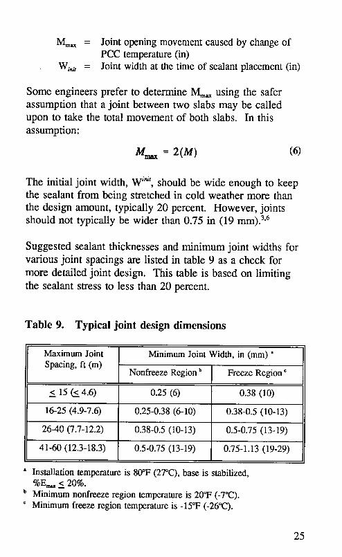
Suggested sealant thicknesses and minimum joint widths forvarious joint spacings are listed in table 9 as a check for
more detailed joint design. This table is based on limiting
the sealant stress to less than 20 percent.
Table 9. Typical joint design dimensions
Maximum Joint Minimum Joint Width, in (mm) "Spacing, ft (m)
Nonfreeze Regionb Freeze Region c
< 15 (S. 4.6) 0.25 (6) 0.38 (10)
16-25 (4.9-7.6) 0.25-0.38 (6-10) 0.38-0.5 (10-13)
26-40 (7.7-12.2) 0.38-0.5 (10-13) 0.5-0.75 (13-19)
41-60 (12.3-18.3) 0.5-0.75 (13-19) 0.75-1.13 (19-29)
• Installation temperature is 80°F (27°C),base is stabilized,%E_ < 20%.
b Minimum nonfreeze region temperature is 20°F (-7°C).c Minimum freeze region temperature is -15°F (-26°(2).
25
The joint reservoir depth, D, should be the sum of theselected sealant thickness, the compressed backer-rodthickness, and the depth that the sealant surface is to berecessed. Some manufacturers recommend that an extra 0.25
in (6 mm) be added when resealing joints to prevent waterand material beneath the sealant from pushing the sealant upand out of the joint.
3.8 Selecting Preparation and InstallationProcedures
The type of joint cleaning procedures and the finalcleanliness of the concrete joint walls prior to sealantinstallation can significantly affect the performance of sealantmaterials. As a rule, the cleaner and dryer the joint surfacesare, the better a sealant will adhere, and the more effective it
will be. Therefore, preparation and installation proceduresshould be chosen as carefully as sealant materials.
The selection of which combination of preparation andinstallation procedures to use should be based on thecondition and requirements of each individual resealingproject. Four combinations are shown in table 10. Eachoption, if followed completely, should result in clean jointsurfaces and increase the chances for good performance.
Option 1 should be considered when:
• The resealing project carries a high volume of traffic.• A high-quality sealant is being used.• Joint widths or depths do not meet the minimum
design requirements.• The existing sealant is hardened and will not melt and
"gum up" the saw blades.
26

Table 10. Joint preparation/installation procedures
Water Initial Sand Final Backer RecessedOpt Plow Saw Wash Airblast Blast Airblast Rod Sealant
1 ./ .( ,f ,f ,f ,( ,f
2 1 1 J J J 1
3 1 1 1 1 1 1 .f
4 _ ,e .f .f ./
Option 2 differs from option 1 only by the elimination ofwaterwashing. This option can be used only when it can bedemonstrated that:
• Sufficient joint surface cleanliness can be achievedwithout waterwashing.
Option 3 adds a plowing operation to the option 2procedures. It should be used when:
• The saw blade is melting the existing sealant andsawing cannot remove the sealant efficiently by itself.
• The joint dimensions are not adequate.
Option 4 replaces the sawing operation with an effectiveplowing operation. It can significantly reduce the preparationtime and, since it is a dry operation, it allows immediatecleaning and resealing. But it may only be used if:
• The joint dimensions are adequate.• The plowing equipment removes more than 95
percent of the sealant from the joint faces, leavingfresh, unspalled concrete.
27

• The sandblaster is able to efficiently remove any
remaining sealant.
If compression seals are being replaced with formed-in-placesealant, sawing is not required when sandblasting cancompletely remove the old lubricant from the joint walls)
Several methods of sealant installation have also been used
with varying results. 1'2 These include:
• Recessing the sealant below the pavement surface• Keeping the sealant surface level with the pavement
surface
• Overbanding sealant onto the pavement surface
The slightly recessed sealant has better potential for long-term performance. The overbanded sealant material istypically worn away by traffic in less than one year. After itis worn, traffic tires tend to pull the sealant from the jointedge. This pulling away has also been noted on somesealants that were installed level with the pavement surface.
3.9 Selecting Equipment
Selection of equipment for the resealing process should bebased on its ability to complete the task. This ability shouldbe proven prior to beginning the resealing operation byconstructing a test resealing section.
A contractor or highway maintenance crew should beallowed to choose the equipment that will effectively cleanand reseal concrete joints in the most efficient manner.However, several items have been shown to be important tosuccessful use of each piece of equipment. Theserequirements are listed in table 11, together with a partial listof equipment manufacturers.
28

Table 11. Joint resealing equipment requirements
Example
Equipment Manufacturers Requirements
RC Company, Non-tapered, carbide-tipped blades.Joint plow Major joint sealing Sufficient blade sizes.
contractors Ability to control blade height.
Ability to force blade against sidewall.
Concrete saw (includes Target, Sclf-prupelled, water-cooled saw > 35 hp.
saw, hose, and water Cimline, Diamond saw blades designed to cuttruck) Magnum, hardened PCC to uniform width.
Diamond Core Cut Controllable, does not pull to one side.
Sandblast equipment Clcmco,
(includes sandblast unit, P.K. IAndsay, Acceptable air compressor.air compressor, hoses, Ingersoll-Rand, Recommend venturi tungsten nozzles.nozzles, and safety Reumclinequipment)
Airblast equipment P.K. Lindsay, Functional oil and water removal(includes air compressor, Ingersoll-Rand, filter on compressor. Minimum 90 lb/in2
hose, wand, and safety Smith, (621 kPa) at 150 ftS/min (71 L/see).equipment) Joy, >_.0.75 in (19 ram) II) hose.
Leroi-Dresser, Nozzle with shut-off valve.
Sullivan Industries Face shield, ear protectors.
Linear Dynamics, Air outlet temperature:
Hot air lance LA Mfg., < 2,000 °F (1,093°C).Cimline, Stream Velocity:
Seal-All, > 1,000 ft/s (1,328 m/s).P.A. Torch No direct flame on pavement.
Backer-rod installation Control Tool, O.J.S. Maintains proper recess, +1/8 in (3 mm).tools Machines, sealing Dix_s not damage backer rod.
contractors
tlot-applied sealant Crafco, Stepp's, Mechanical agitator.
installation equipment Cimline, Cleasby, (recommend full-sweep agitator).
(includes portable Aemil, Bearcat, Separate automatic temperature controlsmelter/applicator, hose, Berry, Westem for oil and melting chamber.
wand and safety ' Industries, White, Sealant heating range to 500*F (260"C).
equipment) Ghausse Sealant recirculation system.
Silicone sealant Pyles-Graco, Inc, Minimum flow rate 0.4 galhnin
installation equipment Am Corporation, (0.025 L/see).
(includes pump, Semco Recommend: hose lined with Teflon, all
compressor, hose, wand) seals and packing made with Teflon.
29

.::... .. .. .::. :_:: ......
•. _: . :
:i:h:..'::_:. :'...
•::.i:.::.. " .:.::
_.:..::.:..:::::
!,'.: .....
._q::.
!!==.::::
:::::::.::....::
•..'.....
•...::...... •...
(i11111:14)..:..:...:
...... :.:.:' ::_: .:::..
• .:::...:..m
.:."..::: .......
' • ': ' .... +:J .::':_.;ii""_ ::. ::_ :.:. "":_'""_:.. "i.i'":...
•":":':'::.:]i"""_::':'"".'"':."!:.:..".'.':""_':].:..':'." !!_i%
i:=i i:: i• ....•..'.::...:..i:._...!:.:...i;....::_..:
Figure 5. Rear-mounted joint plow
3.9.1 Joint Plow
A joint plow used only to remove sealant prior to sawingmust remove enough sealant to keep the saw blades fromgumming up. A shop-made, rear-mounted joint plow for thispurpose is shown in figure 5. If the plow is used withoutresawing, it must be able to efficiently remove at least 95percent of the old sealant from the joint walls and not spallthe joint sidewalls. Plowing has also been successfullyaccomplished by attaching a hydraulically-controlled carbide-tipped blade to the underbody of a small, 18 to 24 hp (13.4to 17.9 kW) tractor, as shown in figure 6. Multiple blade
3O

sizes should be on hand to keep the blades from binding innarrow joints.
Plow blades generally have straight sides, but may betapered. Tapered blades tend to spall the joint edges,especially at intersections with other joints, at pavementedges, and at locations where the joint width changesquickly. Straight-sided blades must be forced against theside of the joints to clean them more thoroughly, but the riskof spalling is greatly reduced when the blade width isnarrower than the joint width.
31

3.9.2 Concrete Saw
Saws used for refacing the joint should remove the mimmumamount of concrete to achieve the design width and producefreshly sawn, clean joints of uniform width and depth. Self-propelled, water-cooled power saws with diamond blades, asshown in figure 7, are typically used for joint refacing.
In many cases, blades are ganged side-by-side on the bladearbor with a solid metal spacer to allow the saw to reface thejoint to a proper, uniform width in one pass. 4 The spacerdiameter must be sized to prevent sealant from building up
32

between the blades. Ganged blades can be exchanged on thearbor to provide more even wear, more uniform sawingwidths, and longer blade life. Single, full-width blades arealso used to resaw joints for resealing.
Since smaller blades are less expensive and make the saweasier to maneuver, blades should be no larger than necessaryto achieve the required depth. Blades specifically designedfor resawing hardened concrete should be used, and the bodyof these blades must be thick enough to resist warping.
3.9.3 Abrasive Blasting Equipment
Sandblasting equipment must be able to completely removedried sawing slurry, dirt, and any old sealant from the jointfaces. To efficiently accomplish this for a medium to largeresealing project, an abrasive blasting unit, as shown infigure 8, should maintain a minimum nozzle pressure of 90lb/in 2 (621 kPa) at 150 ft3/min (71 L/sec). The air supplymust be clean, dry, and free from oil. This may require theinstallation of an oil and moisture filter on the air
compressor.
Tungsten carbide nozzles should be used for larger projects,and ceramic nozzles are more useful for 3- to 4-hour
projects. Tungsten carbide and ceramic nozzles are availablein several diameters, lengths, and shapes. A 0.19- to 0.25-in(5- to 6-mm) diameter venturi nozzle has been usedsuccessfully for sandblasting joints. A sandblast chamberthat allows continuous loading increases production rates.
Attaching an adjustable guide to the nozzle to keep it 1 to 2in (25.4 to 50.8 mm) from the pavement promotes consistentresults and reduces operator fatigue.
33

For worker protection and to conform to state and OSHArequirements, all necessary safety equipment must be presentand in good working condition. This equipment mayinclude:
• A remote shutoff valve
• An air-fed protective helmet• An air supply purifier• Protective clothing for the operator• Portable protective barriers between the sandblaster
and adjacent traffic
34

Figure 9. Air compressor
3.9.4 Airblasting Equipment
An air compressor, as shown in figure 9, is used for finalcleaning, and must produce sufficient air quality, pressure,and volume to thoroughly clean the joints. This requires thefollowing:
• The air supply must be clean, dry, and contain no oil.• A compressor with a minimum of 150 ft3/min (71
L/see) at the nozzle and 100 lb/in2 (690 kPa) must beused.
Many modem compressors automatically insert oil into theair lines to lubricate air-powered tools. For joint cleaning,this must be disconnected and an effective oil and moisture
trap must be installed. In most cases, the inside of the hose
35

for a lubricating air compressor is coated with oil. This oilmust be removed or the hose be replaced to keep oil fromreaching the joints. Attaching a balanced wand with ashutoff control increases safety and improves workercomfort. Proper eye and ear protection should also be usedto protect the operators.
3.9.5 Hot Airblasting Equipment
A hot compressed air lance, or heat lance, used to dryslightly damp joints must supply heated air at about 2,000°F(1,093°C) with a supply velocity of more than 1,000 ft/s (328m/s). The temperature and movement rate must be closelycontrollable to reduce the possibility of overheating thepavement, since overheating can produce chalking andtemperature/steam-induced stress fractures.
Several heat lance options are available, including pushbutton ignition, wheels, and balancing straps. Eye, ear, andbody protection devices must be used, due to the heat andnoise produced by this equipment.
3.9.6 Backer-Rod Installation Tools
A backer-rod installation tool must be able to push thebacker rod into a joint to the specified depth without tearing,stretching, or damaging the rod. Most sealant contractorsmake their own installation tools. However, a lightweight,adjustable tool is commercially available, as well as anautomated, self-guiding unit that is shown in figure 10.
36

_iiii#i!i!iiiiiiiiii_i_ii!_iii_iiiiiiiiiiiiiiiiiiiiiii_....._iiiiiiiiiiiiiiiiiiiiiiiiiiii_
Figure 10. Automated backer rod installation tool
3.9.7 Hot-Applied Sealant Installation Equipment
The equipment used for installing sealant materials that mustbe heated should be able to:
• Effectively raise the temperature of the sealantwithout overheating portions of the sealant
• Allow the operator to maintain exact sealanttemperatures in the range of 325 to 480°F (163 to249°C)
• Be large and powerful enough to heat a sufficientamount of sealant so that installation is not delayed
37

Many companies manufacture mobile equipment that willmelt and pump sealant into pavement joints. Several suchcompanies are listed in table 11. The sealant capacity ofmost melter/applicators ranges from 50 to 350 gal (189 to,1,325 L). Characteristics of the melter/applicator equipmentshould include:
• A double-walled heating chamber with heating oilbetween the walls as the heat transfer medium
• A mechanical agitator• Accurate thermostats to monitor both the sealant and
the heating oil temperatures (these thermostats shouldcontrol the operation of the burners)
• A reversible pump that can feed sealant to theapplicator wand or recirculate the sealant into themelter vat
• A nozzle with an outside diameter that is small
enough to allow it to be pulled through the narrowestjoint without binding, yet large enough to maintain agood installation rate
Options that may be helpful include electronic ignition, dieselheating fuel, wand nozzles that maintain the sealant at acertain depth, s and hoses and wands that are insulated and/orheated.
3.9.8 Silicone Sealant Applicators
Silicone pumps and applicators should provide sealant to thejoint at a rate that does not slow the operator. The applicatorequipment should:
• Not introduce bubbles into the sealant• Not allow air to reach the sealant before it enters the
joint, to prevent premature curing
38

• Maintain a feed rate of at least 0.4 gal/min (1.5L/rain)
• Have a nozzle designed to fill the joint from thebottom up
Applicators that have Teflon-lined hoses and Teflon seals areless likely to allow the sealant to cure in the pump or hosethan those that use neoprene seals and standard hose.
3.9.9 Other Equipment
Under some conditions, a self-propelled vacuum sweeper orportable air blower may be useful for removing sand anddust from the pavement surface prior to backer rodinstallation. Rotary wire brushes have been used for jointwall cleaning with very limited success, due to their tendencyto scrape the cement (which produces dust) and to smear oldjoint sealant over the dust. 6 They are not generallyrecommended.
3.10 Estimating Material, Labor, and
Equipment Requirements
To help with estimating the material, labor, and equipmentrequirements, the information in table 12 is provided. Thistable contains estimated material amounts and preparationand installation rates. Costs and rates for two scenarios are
shown. The first is a self-leveling silicone with a shapefactor of 2:1, and the second is a hot-applied low-modulus,rubberized asphalt.
The plowing rate can be influenced by the number of passesrequired and the difficulty in aligning the blade with thejoint. Sawing rates are influenced by the power of the saw,
39

Table 12. Production rates and material amounts
Number Amounts/Rates (per 1,000 fObof
Workers Silicone Hot-Applied
Average sealant amount" 7-10 gal 13-15 gal
Average plowing rate 2 2-3 hr 2-3 hr
Average sawing rate 1 3.5-7.5 hr 3.5-7.5 hr
Average sandblast rate 2 1.5-4 hr 1.5-4 hr
Final airblast rate 2 1.5-4 hr 1.5-4 hr
Backer-rod installation rate 2 1-3 hr 1-3 hr
Sealant installation rate 2 1.5-2.5 hr 1.5-2.5 hr
• Based on 0.5-in (12.7-mm) joint width.b 1 ft = 0.305 m; 1 gal = 3.79 L
the blade speed, the type and width of blade, the cutting
depth and pressure, the hardness of the concrete, and the size
of the aggregate in the concrete.
Production rates for initial and final airblasting can vary with
the capacity and pressure provided by the air compressor.
Large amounts of debris in the joint or on the pavement
surface will slow the airblasting operation. The rate of
sandblasting is a function of the equipment, nozzle, and
abrasive type used. Where old sealant remains on the joint
walls, the rate of sandblasting will decrease. A 600-1b (272-
kg) capacity sandblast unit with a 0.25-in (6.4-mm) nozzleand 1-in (25.4-mm) inside diameter sandblast hose can use
about 600 lb (272 kg) of abrasive per hour.
40

The rate of primer installation varies greatly with theapplication method. Large-volume spray units result in muchgreater production rates than brushing the sealant on by hand.The speed of backer-rod installation is dependent upon theconsistency of joint width. If joint widths vary significantly,backer rod of different diameters must be used to fill the
joints. This, in turn, requires the installer to carry backer rodof various sizes, and to sometimes install very short lengthsof rod.
The rate of sealant application is controlled by the skill ofthe operator, the distance between joints, the dimensions ofthe sealant reservoir, and the production rate of themelter/applicator (hot-applied) or pump (silicone). Highrainfall frequency can significantly reduce the rate of sealantinstallation, since time must be allowed for the concrete to
dry.
3.11 Determining Cost-Effectiveness
Steps for determining the cost-effectiveness of methods andmaterials for resealing joints in PCC pavements include:
1. Determine the amounts and costs of materials needed.2. Estimate the labor needs and costs.
3. Determine the equipment requirements and costs.4. Estimate the effective lifetime of each resealing
option.5. Calculate the average annual cost for each method
under consideration.
Example calculations are included in appendix B.
41

3.11.1 Material and Shipping Costs
Material and shipping costs can be determined using table13. Material costs for sealant, backer rod, blasting abrasive,primer, and other required materials can be obtained fromlocal suppliers or manufacturers. Coverage rates for sealantcan be estimate_l by using equation 7 or by consultingmanufacturers' literature. By multiplying the material cost,the coverage rate, and the length of the joint to be resealed,the total cost for each material and the overall material costcan be estimate_l.
CR = (__31)( WF)(ST)( W)( T) (7)
where:CR = Sealant coverage rate, ft/gal
(1 ft/gal = 0.08057 m/L)WF = Waste factor (WF = 1.2 for 20 percent waste)ST = Surface type constant (tooled surface: ST = 1.1;
non-tooled surface: ST = 1.0)W = Joint width, in (see figure 4)T = Thickness of sealant, in (see figure 4)
3.11.2 Labor Costs
Labor costs can be determined using table 14. Using thewages for each worker, the number of workers required foreach operation, and the expected time necessary to completeeach operation, the total labor costs can be estimated. Theproduction rates and amounts in table 12 should be helpful indetermining labor requirements. In addition to wage rates,labor costs are greatly influenced by crew productivity andthe need for night work or extra traffic control.
42

3.11.3 Equipment Costs
The cost of equipment will be affected by the availability ofadequate equipment and the need for equipment rental. Theamount of time that each piece of equipment is needed alsogreatly influences equipment costs. By completing table 15and multiplying the daily equipment costs by the number ofpieces of equipment required and the number of days theequipment is needed, the cost of resealing equipment can beestimated. Production rates should be based on local
experience, although the rates shown on table 12 may beused to obtain rough estimates.
3.11.4 User Delay Costs
Although difficult to determine, there is a cost of delay toroadway users during the time that joints are cleaned andresealed. It should be included in cost-effectiveness
calculations if the options being evaluated requiresignificantly different amounts of lane closure. Experiencedtraffic engineers or agency guidelines should be consulted indefining the cost of user delay.
3.11.5 Cost-Effectiveness Comparisons
After the material, labor, equipment, and user costs havebeen determined, the worksheet in table 16 can be used todetermine the annual cost of each resealing option. Theexpected rate of inflation and the estimated lifetime of eachmaterial-placement method option are required inputs for theworksheet.
By comparing the average annual cost of various materialsand repair procedures, the most cost-effective resealingoption can be determined.
43

Table 13. Material and shipping costs
Material Coverage Length TotalMaterial, Unit Cost, Rate, Required, Cost,
S/unit ft/unit ft $
a [ b c abc1
Sealant, gal
Backer rod, ft
Blasting sand, lb
Primer, gal
Total material cost: [
Table 14. Labor costs
Wages, Number Days TotalCrew S/day in Crew Required Cost, $Labor
d e f def
Supervisor
Traffic control
Plowing
Sawing
Initial airblast
Sandblast
Final airblast
Backer rod
Sealant instalation
Total labor cost:
44

Table 15. Equipment costs
Cost, Number Number Total
Equipment S/day of Units of Days Cost, $
h i I ghig
Traffic control
Joint plow
Concrete saw
Air compressor
Sandblast equip.
Installation equip.
Other trucks
Total equipment cost:
45

Table 16. Cost-effectiveness worksheet
Total material cost [table 13] $
Total labor cost [table 14] $
Total equipment cost [table 15] $
Total user delay cost $
Total resealing cost $ (A)
Project length, lane-mi (lane-km) (B)
Average cost, $/lane-mi (S/lane-kin) $ (C)
Estimated lifetime of seal, yrs (D)
Interest rate (typically 0.05) (E)
Average Annual Cost = C[ (E)[(1 +E)°]] (8)[ (1+e)°-1 ]
Average annual cost,$/lane-mi ($/lane-km) $
46

4.0 Construction
Once the design and planning stages are completed, jointscan be prepared in the chosen manner and sealant installed.This construction stage is just as critical as the design stage,since preparing clean joints and correctly installing thesealant material in an effective manner will largely determinethe overall performance of the sealant system design.
This chapter presents the objectives and steps required forcleaning and resealing joints in concrete pavements.Troubleshooting procedures for solving the problemspotentially encountered in each operation are also included.
4.1 Traffic Control
Whenever a joint resealing operation is performed, it iscritical that adequate traffic control be in place to provide asafe working environment for the installation crew and a safetravel lane for vehicles. The operation should also cause theleast amount of disturbance possible to the flow of traffic.
Besides normal signs, arrowboards, cones, and attenuators,flaggers may be required to accompany the sawing and/orplowing operations if the plow or saw must extend into thelane carrying traffic.
4.2 Safety Precautions
The equipment and materials used in a joint resealingoperation can present safety hazards to workers if appropriateprecautions are not taken. All guards must be in place,
47

operational worker protection devices must be used, andappropriate clothing should be worn.
Material safety data sheets should be obtained for eachsealant material to be installed, and proper care should betaken to protect workers from any potentially harmfulmaterials. A more detailed description of safety precautionsrequired for each sealing operation is included in appendix C.
4.3 Preparing the Joints
Objective: To provide clean, dry, properly dimensionedjoints that are free from sawing dust, old sealant, or anyother contamination, and to which sealant material canadequately bond.
Good joint preparation is essential to good sealantperformance. No matter what the sealant material quality is,if the joint faces are not clean and dry, the sealant will pullaway from the joint walls prematurely. Appropriate sealantsplaced in joints that are clean and dry should provideeffective, long-term performance. Successful steps forpreparing joints for sealant installation include removing oldsealant, refacing joint sidewalls, abrasive blasting, airblasting,and installing primer.
4.3.1 Removing the Old Sealant
Plows can be used to remove old sealant from concrete joints
prior to or in place of sawing. Preformed compression sealsshould be removed by hand or by pulling out longer sectionswith a tractor. Plowing involves pulling a thin blade througha joint to remove old sealant and backer material from thereservoir and to clean sealant from the sides of the joint.
48

To effectively remove sealant prior to sawing, the plowingoperation must achieve the following results:
• Sufficient sealant and debris must be removed so that
saw blades are not "gummed up" during sawing.• Joint walls must not be spalled by the plow.
If sawing will not follow the plowing operation, thefollowing additional results must be achieved:
• At least 95 percent of old sealant must be removedfrom the joint sidewalls.
• All sealant remaining on joint sidewalls must beeasily removable by sandblasting.
Several types of plows have been used, and a few havefunctioned successfully. Descriptions of joint plows aregiven in section 3.9.1. Successful use of a joint plowtypically requires the following equipment and procedures:
• A rear- or front-mounted, carbide-tipped plow bladefor partial sealant removal (shown in figure 11), or anundercarriage-mounted carbide blade with hydrauliccontrols for complete sealant removal
• Multiple passes of a blade that is narrower than the
joint, cleaning each channel face individually• Carbide-tipped steel plow blades
• Sufficient tractor weight to maintain blade depth andremove the old sealant
• Effective traffic control and equipment guards toprotect workers from flying debris and moving traffic
Operators must use special care or an alternative procedure ifdifficulties with spalling or improper cleaning areencountered. Several common plowing problems andpossible solutions are listed in table 17.
49
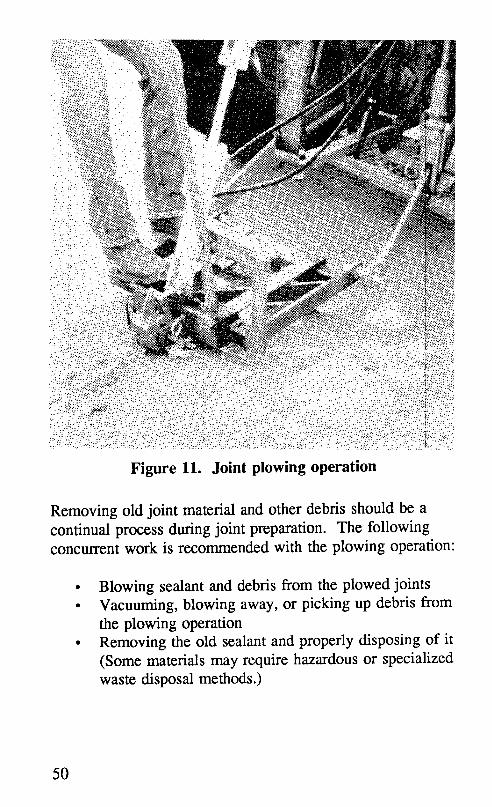
Removing old joint material and other debris should be acontinual process during joint preparation. The followingconcurrent work is recommended with the plowing operation:
• Blowing sealant and debris from the plowed joints• Vacuuming, blowing away, or picking up debris from
the plowing operation• Removing the old sealant and properly disposing of it
(Some materials may require hazardous or specializedwaste disposal methods.)
50

Table 17. Troubleshooting procedures for plowing
Problems Encountered Possible Solutions
Plow is spalling joint edges. Use an untapered plow bit or anarrower blade.
Plow is not completely Increase pressure on the jointremoving sealant, sidewall. Use hand tools.
Belly-mounted plow places Use rear- or front-mountedtractor in traffic, blades, hand tools, or a router.
Guardrail or curb keeps plow Use rear/front-mounted blades.from reaching the entire joint. Reverse the plowing direction.
Use hand tools or a router.
Lining up the plow with a joint Use a belly-mounted plow.is difficult. Use an assistant.
Original saw cuts are offset. Use additional care in plowing.Use hand tools or a router.
4.3.2 Refacing the Joint Sidewalls
Sawing, or refacing, joints in concrete pavements, shown infigure 12, is done either to increase the joint width and depthto the design requirements, or to expose clean, fresh concreteto which new sealant can adhere. Recommendations for
water-cooled saws and blades are discussed in section 3.9.2.
The following results of sawing must be achieved for theentire project:
• Uniform width and depth of joint in compliance withthe design dimensions
• No spalls resulting from resawing
• Sealant completely removed and concrete freshly
exposed on both sides of each joint
51

Figure 12. Joint sawing operation
If the resawing operation is properly completed, theremainder of the preparation tasks are greatly simplified.Therefore, care should be taken to ensure accurate andcomplete sawing, and if poor results are noticed they shouldbe corrected promptly. Several common problemsencountered in resawing are noted in table 18 along withrecommended solutions. Consult saw manufacturers for
other problems and solutions.
Wet-sawing leaves behind old sealant and a slurry of waterand concrete dust in the joint. If this slurry dries on the jointwalls, it is very difficult to remove; if it is not removed, itwill keep new sealant from bonding to the concrete.Therefore, the sealant and slurry must be removedimmediately after sawing by one of the following slurryremoval methods. The first and second methods are more
effective than the third at removing concrete dust slurry.
52

Table 18. Troubleshooting procedures for resawing
Problems Encountered Possible Solutions
Change the rate of sawing.Blade is pulling to one side. Check for rear wheel alignment.
Use wider blades.Blade is not cleaning both Use smaller diameter blades.sides.
Use a more skilled operator.
Sealant is "gumming up"blade. Remove (plow) sealant before sawing.
One side of the ganged blades Switch the inside and outside blades.is worn.
The saw cut does not begin in Have the saw operator take more care.the center of the joint. Replace the saw operator.
Provide an assistant to the operator.
Use a more powerful saw.Use a more appropriate blade.Sawing is slow.Adjust the water feed.Increase the cutting rate.
• Flush the joints with low-pressure watersimultaneously blowing the slurry out with high-pressure air until all sawing waste is removed. 4
• Flush the joints with high-pressure water until allsawing waste is removed.
• Clean the joints with high-pressure air until allsawing waste is removed.
4.3.3 Abrasive Blasting the Joint Sidewalls
An abrasive blasting apparatus is used to direct a mixture ofclean, dry air and abrasive material (typically sand) onto thewalls of concrete joints. Results of abrasive blasting include
53

the removal of sawing dust, old sealant, and other foreignmaterial from the concrete joint surfaces, as well as theroughening of the concrete surface, creating a better bondingsurface. To achieve these results, the abrasive blastingoperation must produce the following effects:
1. Joint walls to which sealant must bond must be free
from all sawing dust, old sealant, lubricant adhesive,discoloration or stain, or any other form ofcontamination.
2. Joint walls must be completely clean, newly exposedconcrete.
The following procedures can provide successful abrasive-blast cleaning results:
1. Use approved sandblast units, safety equipment, _fndsafety procedures, as described in section 3.9.3.
2. Hold the sandblast nozzle no more than 2 in (51 mm)from the pavement surface. A long handle attachedto the hose and extending slightly past the nozzle willallow this to be done from an upright position, asshown in figure 13.
3. Make one complete pass for each joint wall at anangle from the pavement that directs the blast ontothe surface to which sealant must bond.
4. Remove any old sealant with repeat passes or with aknife and repeat passes.
5. Protect traffic in nearby lanes from sand and dust byusing a portable shield and low-dust abrasive.
6. Remove sand and dust from the joint and nearbypavement to prevent recontamination, usingairblasting and/or vacuuming equipment.
54

_...:.::.i.::.:i:_:.:i:.::. : : :_ .:... ".2: .... ...: :: • .. .: ... .. .......................... ............. :................
_ >:::: : : : :=:% _::_::::=::i
Figure 13. Abrasive blasting operation
Problems that are encountered in sandblasting must be solvedquickly. Several common sandblasting problems andpossible solutions are listed in table 19.
The sand and dust must be removed from the joints andpavement surfaces before sealing can begin. If this is notdone, sand and dust can be blown back into the joints,reducing sealant performance. Self-propelled vacuums andportable blowers can be used for debris removal.
55

Table 19. Troubleshooting procedures for sandblasting
Problems Encountered Possible Solutions
Sandblasting is not removing Ensure that sandblaster is functioning.sealant. Cut old sealant away and reblast.
Use a different blaster or abrasive or
larger hoses.Improve the accuracy of sawing.
Sandblast quality is not Ensure that sandblaster is functioning.consistent. Keep the nozzle height and alignment
consistent.
Use a nozzle guide attachment.
Sandblast progress is too Ensure that sandblaster is functioning.slow. Use a different blaster or abrasive or
a larger hose.
There is oil or moisture in the Install a functional oil/moisture filter.sandblast stream. Use another compressor that doesn't
add oil or moisture. Use drier sand.
The operator is quickly Use a guide and handle for uprightfatigued, sandblasting.
Use alternating operators.
4.3.4 Airblasting the Joint Reservoir
After the joints have been sandblasted, and immediatelybefore sealant installation, the dust, dirt, and sand must be
blown from the joints and pavement surface using acompressed air stream. The following results of airblasfing
are desired over the entire project:
• Sand, dust, and dirt must be completely removed fromthe joint reservoir.
• Any sand, dust, and dirt that may recontaminate thejoints must be removed from the surroundingpavement surface.
56
_::__: _:__:i!i::_!!!i_i_ :_!:%ii!!ii_::_i_i::_:_....................:::::::::............
Figure 14. Airblasting operation
Successful airblasting methods for accomplishing theseresults, after the joints are dry and have been sandblasted, arelisted below. In general, joints should be airblastedimmediately prior to backer-rod installation. The airblasting,rod placement, and sealant installation operations must occuron the same day. If rain or dew recontaminate the joints,they must be sandblasted and airblasted again after drying.
1. Use approved air compressors, safety equipment, andsafety procedures, as described in section 3.9.4.
2. Hold the nozzle no more than 2 in (51 mm) from thepavement surface, as shown in figure 14.
3. Blow debris in front of the nozzle. Do not walkbackwards.
57

4. Make slower or repeated passes until the jointreservoir is completely clean.
5. Elevate and fan the nozzle across the pavement on thelast pass to remove debris from the joint area to aplace where it cannot recontaminate the joints.
The most common problems encountered in airblasting arerelated to contamination of the air stream or lack of air
volume and pressure. Methods for addressing these problemsare described in table 20.
Table 20. Troubleshooting procedures for airblasting
Problems Encountered Possible Solutions
Ensure oil/moisture filter is functional.Oil in airstream
Clean or replace the hose.
Moisture in airstrearn Ensure oil/moisture filter is functional.
Use a larger compressor.Air not removing dust, dirt, Use a larger diameter hose.and sand
Reduce the nozzle opening diameter.
If the joints are slightly damp, a heat lance may be used todry the joints prior to installing backer rod? The extremetemperatures that a heat lance can produce (1,500 to 3,000°F[819 to 1,649°C]) can severely spall concrete pavement thatis exposed to the heat for more than a very short time.Extreme care must be taken to keep the heat lance fromremaining in one location for more than 1 to 2 seconds.Pavement that is saturated must be allowed to dry beforeresealing. A heat lance may dry the surface of such apavement for a short time, but capillary action in theconcrete will bring the moisture back to the joint veryquickly.
58

4.3.5 Installing Primer
To effectively and economically prime joint surfaces, theprimer installation process must achieve the following:
• Primer must very thinly and uniformly coat all jointsurfaces to which sealant must bond.
• Primer should not be wasted by applying thick coatsor covering nonessential concrete surfaces.
Primer can be installed using a brush or spray equipment.Spray equipment is much more efficient, generally resultingin a thinner coat, and spray nozzles can be designed to coatonly the upper joint wall surface. It is critical that the primerbe allowed to dry, since as it dries it gives off gas.7 If hot-applied sealant is installed before the primer has dried,bubbles will form in the sealant as the gas tries to escape.All required operator safety equipment must be used. Thismay include goggles, gloves, protective clothing, andrespirators. Manufacturer's recommendations for installationmethods and safety procedures must be followed.
4.4 Material Preparation and Installation
Objective: To properly install backer rod in clean jointchannels and to adequately prepare, install, and shapesealant material.
The preparation and sealing operations should be scheduledso that joints are cleaned and left open for a minimum oftime before resealing. Prepared joints that are left openovernight must be airblasted again and reinspected forcleanliness and dryness. Primer, installed before backer-rodinstallation, must be dry and tack-free. Only a minimumamount of time must be allowed to pass between backer-rodinstallation and sealant placement.
59

No matter how good the joint preparation has been, impropersealant installation can result in rapid seal failure. Therefore,manufacturer's recommendations must be followed regardingminimum placement temperatures, sealant heatingtemperatures, extended sealant heating, and pavementmoisture conditions. Most sealant manufacturers recommend
installing sealant when the pavement is dry and the airtemperature is 40°F (5°C) and rising. Recommendedapplication temperatures for rubberized asphalt sealantsgenerally range from 370 to 390°F (187 to 198°C).
Polymers used in some hot-applied sealants are susceptible todamage from overheating and from extended heating. Theallowable time such sealants may remain at applicationtemperature ranges from 6 hours to 5 days, depending on thesealant properties. Check with sealant manufacturers forexact heating time and temperature limits.
4.4.1 Installing Backer Rod
Backer rod should be installed immediately after airblastingand immediately before placing the sealant. Joint reservoirsand pavement surfaces must be completely clean beforebacker rod is inserted.
Backer rod serves two purposes. First, it helps keep thesealant to its design thickness. Second, it keeps sealant frombonding to the bottom of the joint reservoir. Both thickersealant and sealant bonded to the bottom of the reservoir
place additional stress on the sealant. To perform properlyand reduce sealant stress, the installed backer rod must meet
the following requirements:
• The backer rod must be compatible with andappropriate for the sealant.
• Backer rod must be at the depth required in the plans.
60
• No gaps should be evident between the backer rodand joint walls.
• The rod must be compressed in the joint enough thatthe weight of uncured sealant or the tooling operationdoes not force it down into the reservoir before
curing.• The rod must be dry and clean.• The surface of the rod must not be damaged during
installation.
• No gaps should form between backer rod that isbutted together in a joint or at a joint intersection.
Many methods have been used to insert backer rod intojoints, ranging from poking it in with a screwdriver to usingautomated, self-guided installation equipment. Using ascrewdriver may damage the surface of the rod and result inbubbles forming in the sealant. Automated equipment ismost effective for continuous joints where only one size ofbacker rod is generally needed. The steps to the mostcommonly used and successful method of installing backerrod are listed below:
1. Have enough rod sizes available to fit all of the jointwidths at the project.
2. Use a long-handled installation tool with a large-diameter central disk that fits into all joints and doesnot cut or damage the backer rod, as shown in figure15.
3. Insert one end of the proper size of rod into the endof a joint.
4. Tuck the rod loosely into the joint and push the rodinto the joint to the required depth by rolling theinstallation tool along the joint.
5. Roll over the rod a second time with the installation
tool to ensure proper depth.6. Cut the rod to the proper length, making sure no gaps
exist between segments of backer rod.
61

Figure 15. Backer-rod installation
7. In sections where the rod does not fit tightly to thejoint walls, install larger diameter backer rod.
The depth of the installation tool must be slightly greaterthan the required depth of backer rod. 1° This is because therod compresses slightly when installed. Certain rod materialsare more compressible and require additional tool depth.Stretching and twisting of backer rod must be minimizedduring installation, since, as the material relaxes, gaps mayform at joint intersections and result in sealant failure. Whentransverse and longitudinal joints are being sealed in oneoperation, better results are obtained if rod is installed in theentire length of the transverse joints. That rod is then cut atthe intersection with longitudinal joints and rod is installed in
62

Table 21. Troubleshooting procedures for backer-rodinstallation
Problems Encountered Possible Solutions
Rod is tearing (slivers Use a smaller diameter backer rod.forming) when installed. Ensure that installation tool is smooth.
Side gaps are evident or rodis slipping or is easily Use a larger diameter rod.pushed down in joints.
Check the installation tool for depth.Rod depth is inconsistent.
Repeat passes with the installation tool.
Rod is shrinking in the joint. Do not stretch the rod when installing.
Gaps are formedbetween Use a largerdiameterroller.rod ends.
the longitudinal joints. Possible solutions to commonproblems encountered when installing backer rod aredescribed in table 21.
If delay occurs before installing the sealant, dirt and sand canbe blown into the cleaned joints, or moisture can enter thejoints. When dirt has reentered joints after backer rod hasbeen installed, blow out the dirt using a clean, dry, low-pressure airstream, taking care not to force the rod deeperinto the joint. Damp or wet backer rod must be removedfrom the joints and replaced with dry rod after the reservoiris completely dry and has been recleaned.
4.4.2 Sealant Installation
When the joints are clean, the backer rod is installed and, ifthe temperatures are within the required limits, sealing canbegin. If rain interrupts the sealing operation, reclean the
63

open joints before installing the sealant. The sealingoperation should progress quickly and result in a seal withthe following characteristics:
• Prevents infiltration of water through the joints• Remains resilient and capable of rejecting
incompressible materials at all pavement temperatures• Maintains a tight bond with the sidewalls of the joint• Has no bubbles or blisters
• Is not cracked or split• Cannot be picked up or spread on adjacent pavement
surfaces by tires, rubber-tired vehicle traffic, or theaction of power-vacuum rotary-brush pavement-cleaning equipment after the specified curing period
• Provides a finished, exposed joint surface that isnontacky and will not permit the adherence orembedment of dust, dirt, small stones, and similarcontaminants
4.4.2.1 Hot-Applied Sealant
To install hot-applied sealant that successfully meets theabove requirements, proper heating and installation methodsmust be used. Suitable cleanup and safety procedures, asdescribed in appendix C, must also be followed to ensureworker protection and properly functioning equipment.
Heating the Sealant
Hot-applied sealant performance can be significantly changedby the procedures used to heat and maintain its temperatureduring installation. Prior to heating sealant, the melter/applicator should be checked for the following properties andmodified if necessary:
64

• Carbon buildup on the sides of the heating chambershould be removed.
• All temperature gauges should be accuratelycalibrated.
Heating should be scheduled so that the sealant will be at therecommended temperature when sealing is to begin. Duringinitial heating the following guidelines should be adhered to:
1. Keep the heating oil temperature no more than 75°F(24°C) above the safe sealant heating temperaturestated on the sealant packaging.
2. Keep sealant temperatures between the recommendedpouring temperature and the safe heating temperatureprinted on the sealant packaging.
3. Start the agitator as soon as possible.4. Do not hold the sealant at application temperatures for
a long period before using it.
If sealant is heated above the safe heating temperature, itshould not be used, since rubberized sealants break down andbecome very thin or very stringy when heated above thistemperature. The recommended pouring temperature is thetemperature of the sealant that will achieve the bestperformance. If the sealant is installed below thistemperature, it may cool before it fills the voids in theconcrete, and a poor bond may result. Recommendedpouring temperatures vary between sealant manufacturers andtypes. Therefore, the pouring and safe heating temperaturesof the sealant in use should be obtained from the sealant
packaging, and all sealant operators must be made aware ofit.
The procedures listed below should be followed duringinstallation:
65

1. Check to ensure that the pavement temperature isabove the minimum recommended installation
temperature and above the dew point.2. Check the temperature of the sealant at the nozzle and
adjust the melter controls to obtain the recommendedpouring temperature at the nozzle.
3. Regularly check the sealant temperatures and adjust asnecessary.
4. Watch for carbon buildup on the sidewalls of theheating chamber. This is a sign of overheating.
5. Do not use sealant that has been overheated or heated
for an extended time, or sealant that remains tackyand shows signs of breakdown.
Methods for Installation
Trial installation of at least 15 transverse joints should becompleted using the methods scheduled for use in cleaningand installing sealant on each project. The sealed trial jointsshould be inspected after curing and approved or rejectedprior to sealant placement. Upon approval, the remainingjoints should be cleaned and resealed in the same manner asthe trial joints. Sealing should begin only when the airtemperature is 40°F (8°C) and rising and the air temperatureis above the dew point. The following installation practicesare recommended:
1. Pour the sealant with the nozzle in the joint, so thatthe joint is filled from the bottom and air is nottrapped beneath the sealant.
2. Apply the sealant in one continuous motion whilemoving the wand in a way that the sealant flows outbehind the wand, as shown in figure 16.4
3. Apply sealant in one pass, filling the reservoir to therecommended level. If additional sealant is requiredin low sections, it should be added as soon aspossible.
66

4. Recirculate sealant through the wand into the meltingchamber when not applying sealant.
5. Watch for bubbles, areas of sunken sealant, sealantthat remains tacky, and sealant that has not bonded tothe joint walls, and solve these problems as soon asthey are identified. Several solutions are listed intable 22.
6. Use equipment and installation practices that result inconsistent sealant thickness, little waste, and lowoperator fatigue. Support plates on the wand tip maybe useful for this purpose.
67

Table 22. Troubleshooting procedures for hot-appliedsealant installation
Problem Possible PossibleEncountered Causes Solutions
Reaction with backer rod Use nonreactive rod.
Change rod installationDamaged backer rod method or rod diameter.
Bubbles in Allow joint to dry.sealant Moisture in joint Install above dew point.
Add sealant material.Bubbles in melter
Reduce agitator speed.
Air Irapped by sealant Fill joint from bottom.
Gap remain between rodand wall. Use proper rod diameter.
Sealant is deeply Rod is slipping into joint.sunken in joint.
Gaps remain between Do not stretch rod.backer rod ends. Install rod carefully.
Use a nozzle with a
Operator control is poor. depth control plate.
Sealant recess is Operator movement is Use a wand with auneven, shutoff at the nozzle.not consistent.
Joint width is variable. Use an experienced
Hoses are unmanageable, operator.Provide a hose support.
7. Do not allow traffic onto the pavement until thesealant has set and there is no danger of tracking orstone intrusion.
68

Table 22. Troubleshooting procedures for hot-appliedsealant installation (continued)
Problems Possible PossibleEncountered Causes Solutions
Remove all old sealant,
Joint walls are not clean, oil, dust, dirt, sawingslurry, and othercontaminants.
Wait for concrete to dry.There is moisture on theUse a heat lance if
Sealant is not walls from rain, dew, or slightly damp.condensate.sticking to Install above dew point.concrete walls.
Maintain recommendedSealant temperature is too
sealant temperature.low.Insulate and heat hoses.
Maintain recommendedPavement temperature is
sealant temperature.too low.Insulate and heat hoses.
Kettle is contaminated Remove sealant.
with asphalt, heat Clean and flush kettle.transfer oil, solvent, or Replace with
Sealant remains other sealant, uncontaminated sealant.tacky after
installation. Sealant has been Remove and replace withfresh sealant.
overheated or heated tooCheck melter
long.temperatures.
Cleanup Requirements
Follow the melter/applicator manufacturers' instructions as tothe frequency of cleaning. If carbon is built up on theheating chamber walls, remove it completely by scraping and
69

flushing. Flush the pump and hose with solvent, ifrecommended, and waste the first 3 gal (11 L) of the day toremove any traces of solvent. Dispose of the wastedsealant/solvent solution properly.
Safety Precautions
Obtain the material safety data sheets for each sealantmaterial and follow the worker protection and disposalinsmactions outlined in them. Several safety precautionsshould be followed before, during, and after installation:
1. Be careful when loading blocks of sealant-splashing canoccur.
2. Have operators wear protective gloves and clothing.Sealant and oil temperatures can reach 400°F (204°C),and can cause serious bums.
3. Do not overheat the sealant-it is flammable.
4. Make sure the appropriate hoses (manufacturerrecommended) are used.
5. Follow manufacturers' safety instructions when usingcoal tar compounds. Excessive breathing of fumes orskin contact with coal tar compounds may causeirritation. 7
6. Follow disposal instructions for cleaning solvent andwasted sealant.
4.4.2.2 Cold-Applied Sealant
Several types of sealant are installed without heating; theyinclude polysulfides, polyurethanes, and silicones. Consultmanufacturers' literature for installation recommendations for
each sealant type. The discussion in this manual is limited tothe installation of one-part cold-applied sealants.
70

Loading Sealant into the Pumping Apparatus
Typically, silicone sealant is pumped from storage containersthrough compressed-air-powered pumping equipment to awand with an application nozzle. The sealant is pumpedfrom 5-gal (19-L) buckets or 55-gal (208-L) drums. Twoimportant precautions should be observed when loadingsilicone into an approved pumping apparatus.
• Load the sealant into the apparatus in a manner thatkeeps bubbles from becoming trapped in the sealant.
• Limit the exposure of the sealant to air and moisture,since premature curing can result from such exposure.
Methods for Installation
The following practices have been used successfully and arerecommended for installing silicone sealants.
1. Pour the sealant with the nozzle in the joint, so that thejoint is filled from the bottom and air is not trappedbeneath the sealant.
2. Use a nozzle that applies sealant at a 45° angle, andpush the bead along the joint rather than draw it with thegun leading. An applicator like that shown in figure 17can provide good results.
3. Apply the sealant in one continuous motion, movingsteadily along the joint, so that a uniform bead is appliedwithout dragging, tearing, or leaving unfilled jointspace. 6
4. Adjust the pump rate, nozzle type, and nozzle diameterto control the speed of application.
5. Form a concave surface in non-self-leveling sealantusing a piece of oversized backer rod, a dowel, or othersuitable instrument.
71
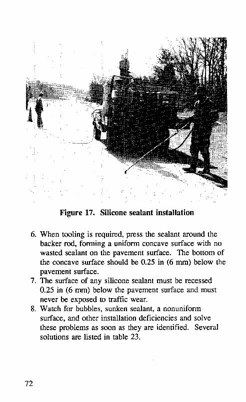
..._.
i
. . . •.....
i
:._: ... ..... ....
Figure 17. Silicone sealant installation
6. When tooling is required, press the sealant around thebacker rod, forming a uniform concave surface with nowasted sealant on the pavement surface. The bottom ofthe concave surface should be 0.25 in (6 mm) below thepavement surface.
7. The surface of any silicone sealant must be recessed0.25 in (6 mm) below the pavement surface and mustnever be exposed to traffic wear.
8. Watch for bubbles, sunken sealant, a nonuniformsurface, and other installation deficiencies and solvethese problems as soon as they are identified. Severalsolutions are listed in table 23.
72

Table 23. Troubleshooting procedures for cold-appliedsealant installation
Problem Possible PossibleEncountered Sources Solutions
Remove all old sealant,
oil, dust, dirt, sawingJoint walls are not clean.slurry, and othercontaminants.
Sealant is notWait for concrete to dry.sticking to Moisture remains on the
concrete walls, joint walls from rain, Carefully use a heat lanceif the pavement surfacedew, or condensate.is slightly damp.
Use more tooling care.Tooling was inadequate.
Use another striking tool.
Gap between rod and wall Use a larger diameterSealant is deeply Rod slipping into joint backer rod.sunken in the
joint. Gaps remain between Do not stretch rod.backer rod ends. Install rod carefully.
Use nonreactive backerReaction with backer rod
rod.
Installed sealant Damaged backer rod Change rod installationmethod or rod diameter.contains bubbles.
Set the pump diaphragmBubbles in pump lines
into sealant better.
Air was trapped by sealant Fill the joint from bottom.
73

Table 23. Troubleshooting procedures for cold-appliedsealant instanation (continued)
Problem Possible PossibleEncountered Sources Solutions
Operator conla'olisUse a "dog-leg"
poor. applicator.Operator movement is
Use an experienceduneven.Joint width is variable, operator.
Sealant recess isnot consistent. Use more tooling care.
Use another strikingtool (large backer rod,
Surface tooling is poor. plastic or rubbertubing on a flexiblehandle).
9. Allow non-self-leveling sealant to become tack free and
self-leveling sealant to skin over before opening the
pavement to traffic. If large pavement deflections areexpected, allow a longer cure time.
Cleanup Requirements
Cleaning the applicator equipment apparatus will be required
if the sealant begins to cure in the pump or hose. Follow the
sealant pump manufacturers' instructions as to cleaning
frequency and required solvents.
74

5.0 Evaluation of Joint SealPerformance
Monitoring the performance of the joint seal repairs is goodpractice, and it can be done rather quickly (in 1 or 2 hours)with fair accuracy. At least one inspection should be madeeach year in order to chart the rate of failure and to plan forsubsequent maintenance. A midwinter evaluation is highlyrecommended, since at that time joints will be near theirmaximum opening and, as a result, adhesion loss can be seenmore easily.
As discussed in section 2.1, a small representative sample ofthe pavement section should be selected for the evaluation.Resistance to the entrance of water and debris to the jointshould be measured by noting the percent of water resistanceloss using equation 1. The joint seal effectiveness can thenbe calculated using the following equation.
%L,g = 100 - _L (9)
where:
%L,H = Percent joint seal effectiveness%L = Percent length allowing water to enter joints..
After a few inspections, a graph of seal effectiveness versustime can be constructed, such as the one in figure 18. Aminimum allowable effectiveness level, commonly 50percent, will help to indicate when additional joint seal repairis required.
75

_n90 " -'_ ProjectedLifeof JointSeal --•,v _ at50%Effeztiveness= 4.8years
__ 70 _l J ' n60
"_ 40r._
30O
20"
1210 1 2 3 4 5 6 7 8
Time after Placement, years.
Figure 18. Example joint seal deterioration chart.
76

Appendix A
Material Testing Specifications
Material testing specifications are listed in tables A-1 to A-3.These specifications are based on specifications prepared bythe American Society for Testing and Materials and by stateshaving significant joint resealing experience.
Specifications are revised frequently, and the sponsoringsociety should be contacted to obtain the latest edition.Information regarding the availability of specifications can beobtained from the agencies listed below.
ASTM SpecificationsAmerican Society for Testing and Materials1916 Race Street
Philadelphia, PA 19103
AASHTO SpecificationsThe American Association of State Highway andTransportation Officials917 National Press BuildingWashington, DC 20004
Federal SpecificationsBusiness Service CenterGeneral Services Administration7th & D Streets, SWWashington, DC 20407
Canadian SpecificationsSecretaryCanadian Specifications BoardNational Research Council
Ottawa 2, Ontario, Canada
77

"S ._ o .............................._ iiii!i!iiiiiiiiiii
::_:_:i:_:!:!:!:_:!:i:i:!:i:!:'_:i:i:i:!:i:i:i:i:i:i:i:i:i:i:_ u iiiiiiiiiiiiiiiiil^1v, ^,iiilliiiiiiil ii :i:i:i:i:!:i:i:!:!
'-1 _ iiiiiiiiiiiiiiiiii..............................!iiiiiiiiiiiiiiiiiiiiiiiiiiii!ii..................'--_ i!i_i_ii{_ii_i_i_ ::;:::::::::::::::
- o :i:i:i:i:i:!:i:i:!:_:i:i:i:!:__ iiii!i!iii!i!ii!il
Vl i:i:i:i:i:i:i:i:!:i:i:i:i:i:i:C_ o '. ..............._, v_ A_.............................................................._ iiiiiiiiiiiiiiiiii..............................iiiiii!!iliiiiii..................:::::::::::::::::::::::::::::: _ :i:i:i:!:!:i:i:i:iiiiiiililiiiiiiiiiiiiiiiiiiiii" i:_:i:_:i:i:_:i:i:........................... .................................. •.-.-.-........................ .........
0 iiiiiiiiiiiiiiiiiiiiiiiiiiiiii................................I..................I..................
"_ ::':'::::'::':':+::':'
._ :=o _ _ _ iiiiiiiiiiiiiiiiiiiiiiiiiiiiii_ {..............................
:_ vl v_ ^l iiiiiii!i!iiiiiiiii!iiiii!iill_ _:i:i:i:i:i:i:i:i:i:i:i:i:i:i:i.oiiiii!i!i!i!i!i!!!!!!!ili!ii!! .................
"_. iiiiiiiiiiiiiiiiiiiii!iiiiiiii i_i_i_i_i_i_iCi_i_i_i_i_i_i_i_iiiii_i_i_i_iCii_iii!iiiiiiiiiiiiii
_ ::::::::::::::::::::::::::::::
<C__ vl vl AI !!iiiiiiiiiiiiiiiiiiiiiiiiiiii............... _ _ _
i_iiiiiiiiiiiiiiiiiiiii_iiii!i:
ill'_1 r_ Ox iil.i_iiiiiiiii:.i!i_ii!iiiiliili_iii!iiiiiiiliiI,,:,_,,,,_,,_,,,!_i_i_!iiiiiii!iii!ii_i_ii_iiiIi_ii_iii_iii_i_i_i_!_i_i_!!_!_iii_iii_iii_ii_iiiiiiiiiiiiiiiiii_=::;i..... _ !iiiiiii_iii!i!i_iiiiiiiiiiiiilliiiiiiiiiiiiiiii!i!i!iii!i!i!i!il!!!ii!!ii!i!ili!i!:,:iiii!iiiiiiililili
_ __- _ _ iiiiiii__ _:ili!i!ii!iiiiiiiiiii!iiiiiiii_iiiiiiiiiiiiiiiil!iiiiiiiii!!ililill< iiiiii!iii!iiiiiii
° .........I i1!o, o iiiiiiiiii!iiiii_I_, _,_ o', ........_ - vl vl iiiiiiiiiiiiiiii_
= <_ iiiiiiiiiiii!iiiii
78

Table A-2. Nonsag silicone sealant specifications
Test State Agency bTest Description " Method
GA DOT MNDOT MIDOT
:::::::::::::::::::::::::::::::::::::::::::::::::::
Tensile stress at 150% ASTM < 45 :iii!iiiiiiiiiiiUiiiiiiiiiiiiiiiiiiiiiiiiiiiiiiii< 45strain, psi O 412(C) iiiiiiiiiiiiiiiiiiiiiiiiiiiiiiiiiiiiiiiiiiiiiiiiii-
ililili_i_ilili_i_ililili_iii_i_iiiiiii!i!iii_iii!
Durometer hardness, ASTM "A .... A .... A"Shore A D 2240 10-25 10-25 5-25
(0 and 77+3°F).;.:.;+;+;.;+;-;.;.;+;.;.;.;.:.;-:.:-;-;-:t+;-:-:+:-:+:-:-:-:-:+:+:+:+;-:.;-:
BondtoPCC State >_50 i_iiii!i!iiii!!!i!ii!_ii!_i!i_!ii!i_!_!_!!i_i_i_i
Table A-3. Self-leveling silicone sealant specifications
Very low Ultra low
Test Description * Test modulus modulus
Method(s)GADOT _ GADOTb
Tensile stress at 150% strain, psi ASTM D < 40 <_ 15
412(C)
Durometer hardness, ASTM D "00 .... 00"
Shore 00 (0, 77+3°F) 2240 40-80 20-80
Bond to PCC mortar, psi State > 40 >__35
Skin-over time, min State < 90 < 90
Extrusion rate, g/min Mil S 8802 > 90 > 100
Nonvolatiles, % State > 90 > 90
Shelf life (months from date of Mfg > 6 > 6
shipment)
Specific gravity D 792 1.1 - 1.5 1.1 - 1.5
Bond (0°F, 10 cycles) State Pass Pass
Ozone, UV Resistance (5,000 State Pass Pass
hrs)
• °C = 0.556(°F - 32); 1 psi = 6.895 kPa
b DOT = Department of Transportation
80

Appendix B
Sample Cost-Effectiveness Calculations
Sample worksheets for cost-effectiveness calculations arepresented in this section. The forms included in section 3.11are used to illustrate the method discussed in that section.Data used for calculation of cost-effectiveness is listed belowand in tables B-1 to B-3.
Sealant Type = Self-leveling silicone sealantShape Factor = 2:1Joint Width = 0.5 in (12.7 mm)Joint Length to Seal = 20,000 ft (6.1 km)
Project Length = 2.5 mi (4.0 km)Primer = None required
Estimated Lifetime = 8 yearsPlow Rate = 525 ft/hr (160 m/hr)Saw Rate = 275 ft/hr (84 rn/hr)
Airblast Rate = 500 ft/hr (152 rn/hr)Sandblast Rate = 375 ft/hr (114 m/hr)
Backer-Rod Install Rate = 540 ft/hr (165 m/hr)Sealant Installation Rate = 540 ft/hr (165 m/hr)
Labor Rates = $120/day
Supervisor Rates = $200/day
81

The sealant coverage rate is calculated in the following
equation.
CR = (2_1)(1.2)(1.0)(0.5)(0.25) = 0.007792
where:
CR = Coverage rate, gal/ftWF = Wastage factor = 1.2W = Joint width, in = 0.5T = Thickness of sealant = 0.25 in
ST = Surface type constant = 1.0
Table B-1. Example material and shipping costs
Material Coverage Length TotalMaterial, unit* Cost, rate, required, cost
S/unit unit/ft ft $/mtrl
a b c abc
Sealant, gal 28.00 0.007792 20,000 4,364
Backer rod, ft 0.10 1.05 20,000 2,100
Blasting sand, lb 0.05 0.20 20,000 200
Primer, gal -0- -0- -0- -0-
Total material cost: 6,664
• 1 gal = 3.785 L; 1 ft = 0.305 m; 1 lb = 0.454 kg.
82

Table B-2. Example labor costs
Wages, Number Days TotalCrew S/day in Crew Required Cost, $Labor
d e f def
Supervisor 200 1 14 2,800
Traffic control 120 1 14 1,680
Plowing 120 2 5 1,200
Sawing 120 1 3.5 420
Initial airblast 120 2 3.5 840
Sandblast 120 2 6 1,440
Final airblast 120 2 3.5 840
Backer rod 120 2 4.6 1,104
Sealant installation 120 2 4.6 1,104
Total labor cost: 11,428
83
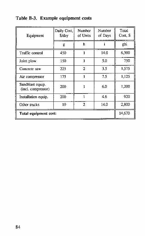
Table B-3. Example equipment costs
Daily Cost, Number Number TotalEquipment S/day of Units of Days Cost, $
g h i ghi
Traffic control 450 1 14.0 6,300
Joint plow 150 1 5.0 750
Concrete saw 225 2 3.5 1,575
Air compressor 175 1 7.5 1,125
Sandblast equip. 200 1 6.0 1,200(incl. compressor)
Installation equip. 200 1 4.6 920
Other trucks 10 2 14.0 2,800
Total equipment cost: 14,670
84

Table B-4. Example cost-effectiveness calculations
Total material cost [table B-l] $ 6,664Total labor cost [table B-2] $ 11,428Total equipment cost [table B-3] $ 14,670User delay cost $ 2,250
Total resealing cost $ 35,012 (A)
Project length, lane-mi 2.5 (B)Avg. resealing cost, $/lane-mi $ 14,005 (C)Estimated lifetime of seal, yrs $ 8 (D)Interest rate (typically 0.05) $ 0.05 (E)
Avg. Annual Cost-- C (E)[(1 +E) D](1 +E) v- 1
[(0.05)[(1+0.05)811 : $2,167Avg. Annual Cost = 14,005 [ (1+0.05) s-1
Average annual cost, $/lane-mi $ 2,167
Using a modified D-3405 sealant that costs $3.50 per gallon
and lasts five years, together with the same preparation
methods listed above, the computed average annual cost is$2,932/lane-mi.
Avg. Annual Cost = 12,696 [(0.05)[(1 +0.05)s]] = $2,932[ (1 -1J
85
Appendix C
Material and Equipment SafetyPrecautions
Mandated highway safety attire, such as vests and hard hats,should always be worn by crews and supervisors duringsealing operations. In addition, individual crews should bemade aware of all safety precautions associated with thematerials and equipment with which they are working.
C.1 Materials
In order to protect the health and well-being of maintenanceworkers who handle the various sealant materials, materialsafety data sheets (MSDS) should be obtained frommanufacturers of all materials to be installed and these sheets
should be reviewed by those handling the materials. Thesesheets provide important information about health hazards,fire and explosion data, reactivity data, and safe usage anddisposal.
Every effort should also be made to determine the type ofsealant material to be removed and to address any safetyhazards that it may present.
C.I.I Hot-Applied Sealants
Hot-applied sealants require that several safety precautions befollowed:
1. Be careful when loading blocks of sealant-splashing mayoccur.
87

2. Have operators wear protective gloves and clothing.Sealant and oil temperatures can reach 400°F (204°C),and can cause serious bums.
3. Do not overheat the sealant-it is flammable.
4. Follow manufacturers' safety instructions when using coaltar compounds. Excessive breathing of fumes or skincontact with coal tar compounds may cause irritation orpossibly more serious health problems.
5. Use care with any solvents required for cleanup.6. Dispose of diluted or wasted sealant as specified in the
MSDS.
C.1.2 Cold-Applied Sealants
When working with cold-applied sealants, care should betaken to protect workers from skin, eye, or internal contactwith sealant materials. MSDS and manufacturer's
recommendations should be consulted to determine specificsafety requirements for each sealant material.
88

Appendix D
Inspection Checklists for Construction
This section is intended for use by inspectors of resealingprocesses, as well as by supervisors and contractors. Itcontains discussions of planning, equipment, and procedurescritical to the successful completion of a resealing project.Checklists pertaining to each step of the process, includingplanning, equipment, material preparation, joint preparation,sealant installation, final inspection, and safety precautions,are included.
Field experience has shown that each step in the resealingprocess requires careful supervision and inspection. Aninspector must continually observe the various operations toensure that proper procedures are being continuallyperformed. In most cases, it is the contractor's responsibilityto effectively clean and reseal the joints, and it is theinspector's responsibility to continually monitor the work andensure that corrections are made if requirements are not met.
89

D.1 Preconstruction Plans and Specifications
Plans must be prepared and distributed to the inspector(s)and the supervisor(s) of the installation crew. It isrecommended that the inspectors and the constructionsupervisors meet before work begins to discuss the plans andspecifications. Information that must be contained in theplans includes the following:
[] 1. Project layout, including stationing and slablengths
[] 2. Original joint reservoir dimensions, includingexisting variability
[] 3. Original sealant material type[] 4. Location and type of required pre-resealing
repairs[] 5. Required reservoir dimensions[] 6. Required sealant thickness[] 7. Required sealant recess below pavement surface
Specifications may be based on adherence to designatedprocedures, on achieving a quality end product, or acombination of the two. Information that must be contained
in procedure-based specifications includes the following:
[] 1. Lot testing requirements[] 2. Delivery and storage requirements[] 3. Repair methods and materials for pre-resealing
repairs[] 4. Equipment requirements[] 5. Material requirements[] 6. Preparation procedure requirements[] 7. Installation procedure requirements[] 8. Weather condition limitations
[] 9. Traffic shutdown requirements.[] 10. Safety requirements[] 11. Material disposal requirements
90

If end-result specifications are used, the followinginformation must be included:
[] 1. Lot testing requirements[] 2. Delivery and storage requirements[] 3. Repair methods and materials for pre-resealing
repairs[] 4. Required results of each preparation procedure
and acceptance/rejection criteria[] 5. Required results of the installation process and
acceptance/rejection criteria[] 6. Weather condition limitations[] 7. Limitations of traffic shutdown
[] 8. Safety requirements[] 9. Material disposal requirements
An example of installation acceptance criteria is included insection D.4. In most cases, a combination of procedure-based and end-result specifications is used, and the followinginspection process is based on a combination of the two.
D.2 Equipment Inspection
All equipment must be inspected and approved before theproject begins, as well as during joint preparation and sealantinstallation. A list of proposed equipment should besubmitted before installation for approval. DuringpreinstaUation inspection, the inspector should check allequipment to be used on the project, making sure that eachpiece meets the requirements of the project specifications orthe suggested requirements listed in table 11. If questionsarise about the suitability of the equipment, a statement fromthe sealant manufacturer should be supplied indicating thatthe equipment is acceptable for installing the sealant.
91

The condition and effectiveness of each piece of equipmentshould be checked during trial installation and at thebeginning of each day of preparation and installation.Criteria for equipment effectiveness are listed in thefollowing sections.
D.3 Field Installation Inspection
After all required spall repair, load transfer restoration, slabstabilization, grinding, and other rehabilitation have beencompleted and approved, the resealing process can begin. Itis recommended that the inspector(s) and supervisor(s) meetbefore work begins to discuss the following subjects:
1. Exact locations and amounts of all joints to beresealed (Boundaries should be clearly marked.)
2. Traffic control requirements and lane closuretime limitations
3. Methods required for cleaning and resealingjoints (if procedure-based specification)
4. Criteria for approval of all cleaning andinstallation equipment and processes
5. Final criteria for approval of resealing work,including procedures and penalties for rejection
6. Any localized variations from the specifiedmethods
7. Safety requirements for all equipment andprocedures (including material disposalrequirements)
8. Procedures in the event of wet or cold weather
9. Procedures in the event that seal qualityrequirements are not met
92

D.3.1 Inspection of Joint Preparation
Joint preparation, as discussed in this manual, refers tosealant removal, joint refacing, final cleaning, primerinstallation, and backer rod insertion. Sealant manufacturers'instructions should be followed when preparing joints unlessnoted otherwise in the plans and specifications. Thefollowing inspection checklist can be used to ensure thatjoint preparation is completed properly. 6 Not all of thesecleaning processes are used, in many cases.
[] 1. Joint plowing:[] Plow is removing the required amount of
sealant.
[] Plow is not spalling the joint edges.[] Worker and driver safety are not
compromised.
[] 2. Concrete sawing:[] Saw is removing the required amount of
concrete and sealant.
[] Saw is uniformly cutting to the properwidth and depth (depth and width can bechecked quickly using a metal template).
[] Saw is refacing both sides of the joint.[] All guards and safety mechanisms are
functioning properly.[] All sawing slurry is immediately removed
from the joints.
[] 3. Waterwashing:[] Equipment is removing all sawing slurry
and old sealant from the joints.[] No standing water remains in the joints.
93
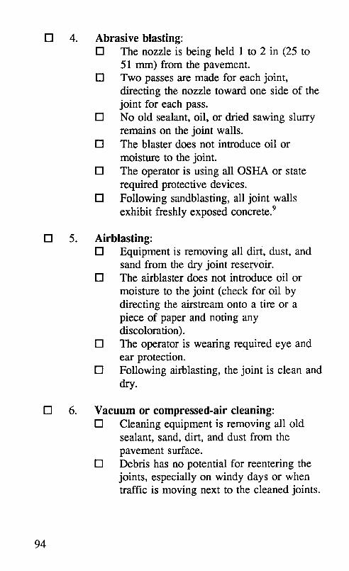
[] 4. Abrasive blasting:[] The nozzle is being held 1 to 2 in (25 to
51 mm) from the pavement.[] Two passes are made for each joint,
directing the nozzle toward one side of thejoint for each pass.
[] No old sealant, oil, or dried sawing slurryremains on the joint walls.
[] The blaster does not introduce oil or
moisture to the joint.[] The operator is using all OSHA or state
required protective devices.[] Following sandblasting, all joint walls
exhibit freshly exposed concrete. 9
[] 5. Airblasting:[] Equipment is removing ail dirt, dust, and
sand from the dry joint reservoir.[] The airblaster does not introduce oil or
moisture to the joint (check for oil bydirecting the airstream onto a tire or apiece of paper and noting anydiscoloration).
[] The operator is wearing required eye andear protection.
[] Following airblasting, the joint is clean anddry.
[] 6. Vacuum or compressed-air cleaning:[] Cleaning equipment is removing all old
sealant, sand, dirt, and dust from thepavement surface.
[] Debris has no potential for reentering thejoints, especially on windy days or whentraffic is moving next to the cleaned joints.
94

[] 7. Primer application:[] Primer applicator is applying a thin layer
of sealant uniformly over joint faces toreceive sealant.
[] All required safety protection equipment isin use and operational.
[] Primer is allowed to dry before backer rodis inserted.
[] 8. Backer-rod installation:
[] The rod is inserted into the joint uniformlyto the required depth without stretching ortearing it. Depth can be checked using atemplate (slivers of rod in the joint indicatethat the rod is too large).
[] The rod remains tight in the joint withoutgaps along the sides, at joint intersections,or between rod segments.
[] The rod is compressed in the joint enoughthat the weight of the uncured sealant orinstallation equipment or tooling equipmentwill not force it down into the joint.
[] A larger diameter rod is used in wide jointsections.
[] 9. Low-pressure air cleaning:[] When needed, all dust or dirt that has
reentered clean joints that contain backerrod is blown out.
[] The backer rod is not pushed into the jointby the airstream.
Water on the joint walls during sealing will severely reducethe ability of the sealant to bond to the walls, and can resultin bubbles in some sealants. Check frequently for dew thatmay collect in the joints and remain after the surface is dry,particularly if temperatures and humidity levels have been at
95

or are close to the dew point. If cleaned joints arerecontaminated by rain, dew, dirt, or oil, they should berecleaned in a manner that restores cleanliness. This may
require sandblasting and airblasting or merely airblasting.Cleaned joints that are left overnight should, at a minimum,be airblasted again. Moist backer rod should be removedand replaced.
One method that an inspector can use to communicate theneed for additional preparation at a particular joint is to marknear it with a particular color of paint. 6 A possible patternthat could be used is the following.
1. Yellow - Repairs must be made to joint before sealing.2. Orange - Joint is not the proper size.3. Red - Joint is not properly cleaned.4. Blue - Backer rod is not tight or is not at proper
depth.5. Brown - Improper sealing technique (too full, too
low, tacky sealant, not tooled correctly,bubbles in sealant, sealant not bonded, etc.)
The contractor or supervisor can use green spray paint toindicate that the problem is repaired and the inspector shouldreexamine the joint for approval.
96

D.3.2 Inspection of Joint Sealant Installation
The inspector should watch for several items prior to andduring installation of the sealant material. The followingsection is a checklist for inspection of joint sealantinstallation.
D.3.2.1 Hot-Applied Sealant Installation Inspection
When inspecting the installation of hot-applied sealantmaterials, the following pieces of information must bedetermined before heating begins. This information can beobtained from sealant manufacturers and from the projectplans and specifications:
[] 1. The recommended sealant applicationtemperature
[] 2. The safe sealant heating temperature[] 3. The length of time that a sealant can be heated
before it begins to break down[] 4. The required thickness of sealant[] 5. The required sealant recess below the pavement
surface
[] 6. The air temperatures allowable for sealing[] 7. The average sealant curing time and the time
before traffic can be allowed on the pavementafter resealing
[] 8. The material safety data sheets (MSDS)[] 9. The criteria for acceptance/rejection of resealing
work, and the penalties associated with rejection[] 10. Acceptable test results for all materials to be
installed
[] 11. The production date and shelf life of allmaterials
97

During installation of hot-applied sealants, the followingitems should be regularly checked to ensure that they meetthe requirements:
[] 1. All joints remain clean and dry.[] 2. All backer rod remains tight in the joint at the
correct height with no gaps.[] 3. The melter/applicator maintains the sealant at
the required temperature without overheating.[] 4. Sealant leaving the nozzle is at the application
temperature.[] 5. The agitator is functioning properly.[] 6. No carbon is built up on the melting chamber
walls.
[] 7. All thermometers and temperature controls aremonitored and functioning properly.
[] 8. The operator is not trapping bubbles in thesealant or overfilling or underfilling the joints.
[] 9. Spilled sealant is removed from the pavementsurface.
[] 10. Areas of low sealant are not present or arequickly filled. Steps are taken to eliminate thecause of the low sealant.
[] 11. All required operator safety equipment is in use.This applies especially to D-3406 materials.
Warning: If white smoke is seen rising from the kettle,stop the operation immediately and check the sealanttemperature. If the sealant remains tacky in the joint longafter placement, or the sealant becomes stringy inside themelting chamber, the sealant has been overheated and shouldbe completely removed from the chamber and wasted.
98

D.3.2.2 Silicone Sealant Installation Inspection
Prior to installation of silicone sealants, the followinginformation should be obtained by the inspector:
[] 1. The expiration date of the sealant material[] 2. The air temperatures allowable for sealing[] 3. The required thickness of sealant
[] 4. The required sealant recess below the pavementsurface
[] 5. The need for tooling the surface of the sealant[] 6. The average sealant curing time and the time
before traffic can be allowed on the pavementafter resealing
[] 7. Safety data from the MSDS
[] 8. The criteria for acceptance/rejection of resealingwork and penalties for rejection
[] 9. The acceptable results of lot tests for allmaterials
[] 10. The production dates and shelf life of allmaterials
As sealant installation continues, the following items shouldbe regularly checked for compliance with the plans andspecifications:
[] 1. All joints remain clean and dry.[] 2. Backer rod remains tight in the joint at the
correct height with no gaps.[] 3. The silicone applicator system is not introducing
bubbles to the sealant.
[] 4. The applicator, wand, and controls allow theoperator to fill the joint uniformly to the correctlevel.
[] 5. The operator is not trapping bubbles in thesealant.
99

[] 6. The operator is not overfilling or underfilling thejoints (sealant thickness and recess can bechecked by inserting a thin ruler through theuncured sealant to the top of the backer rod).
[] 7. Non-self-leveling silicone sealant is tooledimmediately, forcing sealant against the jointwalls and creating a smooth concave surface.
[] 8. Any sealant that remains on the pavementsurface is removed.
[] 9. Areas of low sealant are not present or are
quickly filled. Steps are taken to eliminate thecause of the low sealant.
[] 10. All required operator safety equipment is in use.[] 11. Traffic is not allowed on the pavement until the
sealant is skinned over and cannot be damaged.
D.4 Final Inspection
During installation and prior to approval, the resealed jointsshould be individually inspected, ensuring that the sealantmeets the following criteria, and noting the presence andseverity of any distresses. 4'6
[] 1. Sealant is bonded firmly to the joint sidewalls(cured sealant material should not separate fromthe sidewalls when pulled lightly with thefingertips across the joint).
[] 2. Sealant is not tacky after curing and will notpermit adherence of dust, dirt, or small stones.
[] 3. Sealant material contains no cracks, bubbles, orblisters.
[] 4. Sealant cannot be picked up or spread onadjacent pavement surfaces by tires, rubber-tiredvehicle traffic, or the action of power-vacuum
100

rotary-brush pavement-cleaning equipment afterthe specified curing period.
[] 5. Sealant is resilient and capable of rejectingstones at high pavement temperatures.
[] 6. Sealant is recessed to the correct depth belowthe pavement surface (this is critical for siliconesealants, as they are not resistant to trafficwear).
[] 7. Sealant spilled on the pavement surface has beenremoved.
[] 8. No debris remains on the pavement surface.
101

Appendix E
Partial List of Material andEquipment Sources
This section contains information for contacting severalmanufacturers of sealant materials, backer rod, andinstallation equipment. Addresses and phone numbers are
given for manufacturers and/or suppliers who can provide theinquirer with information regarding material properties,recommended installation practices, safety procedures, andlocal suppliers.
Material safety data sheets that describe the material
components, any hazardous properties, and any requiredprotective equipment, should be available from all sealantmanufacturers.
Sealant Materials
Manufacturers of D-3405 and Modified D-3405 Hot-Applied Sealant
Crafco Incorporated W.R. Meadows, Inc.6975 W. Crafco Way P.O. Box 543Chandler, AZ 85226 Elgin, IL 60121(602) 276-0406 (708) 683-4500(800) 528-8242
Koch Materials Company4334 NW Expressway, Ste. 281Oklahoma City, OK(405) 848-0460(800) 654-9182
103

Manufacturers of Self-Leveling and Non-self-LevelingSilicone Sealant
Crafco Incorporated Dow Coming Corporation6975 W. Crafco Way Midland, MI 48686-0094Chandler, AZ 85226 (517) 496-4000(602) 276-0406(800) 528-8242
Mobay CorporationMobay RoadPittsburgh, PA 15205-9741(412) 777-2000
Backer Material
Manufacturers of Expanded Closed-Cell Foam Rod
Applied Extrusion Technologies, Inc.P.O. Box 582
Middletown, DE 19709(302) 378-8888(800) 521-6713
Industrial Thermo Polymers Limited1255 Lorimar Drive
Mississauga, ON, Canada L5S 1R2(416) 795-1254(800) 387-3847
104

Sealant Installation Equipment
Manufacturers of Melter/Applicators for Hot-AppliedSealants
Cimline, Inc.7454 Washington Avenue SouthEden Prairie, MN 55344(800) 328-3874
Crafco Incorporated6975 W. Crafco WayChandler, AZ 85226(800) 528-8242
Stepp Manufacturing Company, Inc.North Branch, MN 55056(612) 674-4491
White Asphalt EquipmentMidwest Tank and Mfg. Co., Inc.2075 S. Belmont Avenue
Indianapolis, IN 46221(317) 632-9326
Manufacturer of Pump Applicators for Cold-AppliedSealants
Pyles Business UnitGraco, Inc.28990 Wixom Road
Wixom, MI 48096(313) 349-5500
105

Manufacturers of Automated Backer-Rod InstallationDevices
O.J.S. Machines5842 Sackville CloseHumble, Texas 77346
(713) 853-7072
Manufacturers of Joint Plows
RC Company7207 Stutz LaneBethalo, IL 62010(618) 258-1044
106

Glossary
Adhesion failure-Complete loss of bond between a sealantmaterial and the concrete joint wall.
Allowable extension-The amount of stretching of a sealantmaterial under which performance is estimated to beadequate.
Average daily traffic (ADT)-The total traffic volumecarded by a pavement during a given period (inwhole days), greater than 1 day and less than 1 year,divided by the number of days in that period.
Blowups-The result of localized upward movement orshattering of a slab along a transverse joint or crack.
Channel face-The vertical concrete sidewall of a sawedjoint sealant reservoir.
Compression seals-Preformed seals, generally made fromneoprene, that can be compressed and inserted intoconcrete joints for sealing purposes.
Corner break-A diagonal crack forming between transverseand longitudinal joints that extends through the slab,allowing the comer to move independently from therest of the slab.
D-cracking-The breakup of concrete due to freeze-thawexpansive pressures within certain susceptibleaggregates (also called durability cracking).
107

Embedment-To become fixed firmly in a surroundingmass, as stones sink into and become fixed in softsealant material.
Extruded-Forced through a die to give the material acertain shape.
Flow-The sinking of unstable sealant into a sealantreservoir.
Horizontal movement--Opening and closing of jointsresulting from pavement expansion and contraction.
Incompressible-Material that resists compression, asstones, sand, and dirt in a crack or joint reservoir thatis closing.
Joint growth-The gradual increase in joint width resultingfrom the filling of joints with incompressiblematerials during cold cycles.
Joint sidewalls-The vertical concrete edges of a sawedjoint reservoir.
Life-cycle cost analysis-An investigation of the presentand future costs of each repair alternative, taking intoaccount the effects of both inflation and interest rates
on expenses over the life of the project.
Load transfer-The transfer of load across a joint or crackin concrete pavement resulting from aggregateinterlock, dowels, or other load-carrying devices.
Overhanding-Spreading a thin layer of sealant (about 1.5in [38 mm] wide) onto a pavement surface centeredover a joint or crack at the same time that the sealantreservoir is filled.
108

Pumping-The ejection of water and fine materials frombeneath a concrete pavement through cracks or jointsunder pressure from moving loads.
Refacing-Removing about 1/16 in (1.6 mm) of concretefrom each wall of a sealant reservoir using diamondsaw blades.
Resealing-Replacing sealant in joints or cracks, preferablyusing good-quality methods and materials.
Sealant�channel interface-The vertical edge of a sealedjoint where sealant material and concrete joint facemeet.
Sealant reservoir-The channel along a joint or crack thathas been widened by sawing to allow sealant to beplaced in it.
Sealant system-All components that function to seal joints,i.e., sealant material, surrounding concrete, andsealant/concrete interface.
Slurry-The mixture of water, concrete dust, old sealant,and dirt that results from resawing a joint in concretepavement.
Subdrainage-Drainage of moisture from beneath apavement by means of a porous subbase materialconnected to outlet drain lines.
Track-The spreading of unstable sealant material along thepavement surface by traffic tires.
Undersealing-Filling voids beneath a concrete pavementusing a pressurized slurr3, or hot asphalt material.
109

Vertical shear-Vertical stress along the sealant/concreteinterface resulting from traffic loading, curling, andpavement faulting.
Weathering-Breakdown of sealant material resulting fromthe effects of moisture, ultraviolet rays, and time.
110

References
1. Smith, K. L., D. G. Peshkin, E. H. Rmeili, T. VanDam, K. D. Johnson, M. I. Darter, M. C. Belangie,and J. A. Crovett. Innovative Materials and
Equipment for Pavement Surface Repairs. Volume I:Summary of Material Performance and ExperimentalPlans (report no. SHRP-M/UFR-91-504), and VolumeH: Synthesis of Operational Deficiencies of EquipmentUsed for Pavement Surface Repairs (report no. SHRP-M/UFR-91-505). Strategic Highway ResearchProgram, National Research Council, Washington,DC: 1991.
2. Evans, L. D., G. Good Mojab, A. J. Patel, A. R.Romine, K. L. Smith, and T. P. Wilson. InnovativeMaterials Development and Testing-Volume 1: ProjectOverview (report no. SHRP-H-352); Volume 2:Pothole Repair (report no. SHRP-H-353); Volume 3:Treatment of Cracks in Asphalt Concrete-SurfacedPavements (report no. SHRP-H-354); Volume 4: JointSeal Repair (report no. SHRP-H-355); and Volume 5:Partial Depth Spall Repair (report no. SHRP-H-356).Strategic Highway Research Program, NationalResearch Council, Washington, DC: 1993.
3. Collins, A. M., W. D. Mangum, D. W. Fowler, andA. H. Meyer. Improved Methods for Sealing Joints inPortland Cement Concrete Pavements. Research
Report 385-1, FHWA/TX-87-385-1. Center forTransportation Research, University of Texas atAustin: 1986.
4. Darter, M. I., E. J. Barenberg, and W. A. Yrandson.NCHRP Research Report 1-21: Joint Repair Methodsfor Portland Cement Concrete Pavements.
111

Transportation Research Board, National ResearchCouncil, Washington, DC: 1971.
5. Carpenter, S. H., M. R. Tirado, E. H. Rmeili, andG. L. Perry. Methods for Shoulder Joint SealingVolume I: Serviceability Requirements. Report no.FHWA/RD-87. Federal Highway Administration,U.S. Department of Transportation, Washington, DC:1987.
6. "Rigid Pavement Design for Airports-Chapter7-Standard Practices for Sealing Joints and Cracks inAirfield Pavements," Air Force Manual 88-6. 1983.
7. Guide to Sealing Joints in Concrete Structures. ReportACI 504R-90. American Concrete Institute: 1990.
8. Bugler, _I.W. "Problems and Solutions in RigidPavement Joint Sealing," Public Works, September1983.
9. Mildenhall, H. S., and G.D.S. Northcott. A Manualfor Maintenance and Repair of Concrete Roads.Department of Transportation, Cement and ConcreteAssociation.
10. Blais, E. J. Value Engineering Study of Crack andJoint Sealing. Report no. FHWA-TS-84-221. FederalHighway Administration, U.S. Department ofTransportation, Washington, DC: 1984.
112

Materials and Procedures
for Rapid Repair of Partial-DepthSpalls in Concrete Pavements
Manual of Practice
.i.::!i.i... .... '. " • ._i_:_:_
. :: ..:...... .
:_i::_::. ....._..:.... .i...... :::::: _.......
Strategic Highway Research ProgramNational Research Council

Contents
1.0 Introduction ............................. 11.1 Scope of Manual ...................... 11.2 Purpose of Partial-Depth Spall Repair ....... 11.3 Partial-Depth Patch Performance ........... 21.4 Limitations .......................... 3
2.0 Need for Partial-Depth Spall Repair ............ 52.1 Pavement Condition .................... 52.2 Climatic Conditions .................... 7
3.0 Planning and Design ....................... 93.1 Objectives in Selecting Materials and
Procedures .......................... 9
3.2 Assessing Existing Conditions ............ 103.3 Selecting a Repair Material .............. 11
3.3.1 Cementitious Concretes ........... 143.3.2 Polymer Concretes .............. 173.3.3 Bituminous Materials ............. 18
3.3.4 Material Testing ................ 193.4 Selecting Accessory Materials ............ 20
3.4.1 Bonding Agents ................ 203.4.2 Joint Bond Breakers ............. 203.4.3 Curing Materials ................ 213.4.4 Joint Sealants .................. 23
3.5 Selecting Dimensions of the Repair Area .... 233.6 Selecting Patch Preparation Procedures ..... 29
3.6.1 Saw and Patch ................. 29
3.6.2 Chip and Patch ................. 313.6.3 Mill and Patch ................. 323.6.4 Waterblast and Patch ............. 333.6.5 Clean and Patch ................ 36

3.7 Estimating Material, Equipment, andLabor ............................ 36
3.8 Overall Cost-Effectiveness .............. 383.8.1 Cost-Effectiveness Worksheet ....... 38
3.8.2 Determining Cost-EffectivenessInputs ....................... 51
4.0 Construction ............................ 534.1 Traffic Control ...................... 53
4.2 Safety Precautions .................... 544.3 Material Testing ..................... 544.4 Initial Joint Preparation ................ 55
4.4.1 Removing Old Sealant ............ 554.4.2 Joint Sawing ................... 564.4.3 Sawing Out Joint Inserts .......... 56
4.5 Removing the Deteriorated Concrete ....... 574.5.1 Saw and Patch ................. 58
4.5.2 Chip and Patch ................. 604.5.3 Mill and Patch ................. 634.5.4 Waterblast and Patch ............. 634.5.5 Clean and Patch ................ 65
4.6 Cleaning the Repair Area ............... 654.6.1 Sandblasting ................... 654.6.2 Airblasting .................... 664.6.3 Sweeping ..................... 67
4.7 Final Joint Preparation ................. 674.7.1 Preparing Transverse Joints ........ 694.7.2 Preparing Centerline Joints ......... 694.7.3 Preparing Lane-Shoulder Joints ...... 704.7.4 Using Flexible Repair Materials ..... 71
4.8 Pre-Placement Inspection of the RepairArea .............................. 71
4.9 Mixing the Bonding Agent .............. 714.10 Mixing the Repair Material .............. 72
4.10.1 Cementitious Concretes ........... 72
4.10.2 Polymer Concretes .............. 734.10.3 Bituminous Materials ............. 74
ii

4.11 Applying the Bonding Agent ............ 754.12 Placing the Repair Material .............. 76
4.12.1 Cementitious Concretes ........... 77
4.12.2 Polymer Concretes .............. 774.12.3 Bituminous Materials ............. 78
4.13 Consolidating and Compacting ........... 794.14 Screeding and Finishing ................ 814.15 Curing ............................ 81
4.15.1 PCC Patching Materials ........... 824.15.2 Proprietary Patching Materials ...... 83
4.16 Joint Sealing ........................ 844.17 Cleanup Requirements ................. 844.18 Opening to Traffic .................... 844.19 Inspection ........................... 86
5.0 Evaluating Partial-Depth Patch Performance ...... 875.1 Data Required ....................... 875.2 Calculations ........................ 88
Appendix A Material Testing Specifications ......... 93Appendix B Sample Cost-effectiveness Calculations ... 95Appendix C Material and Equipment Safety
Precautions ...................... 109
Appendix D Inspection Checklists for Construction ... 111Appendix E Partial List of Material and Equipment
Sources ......................... 123
Glossary .................................. 129References ................................ 137
iii

List of Figures
Figure 1. Partial-depth spall caused byincompressibles ..................... 6
Figure 2. Scored joint bond breaker ............. 22
Figure 3. Dimensions of patch at one joint ........ 25
Figure 4. Dimensions of patch at one joint for spallsless than 12 in apart ................. 26
Figure 5. Dimensions of patch at two joints ....... 27
Figure 6. Dimensions of patch at two joints for spallsless than 12 in apart ................. 28
Figure 7. Recommended orientation of milled patch.Milled patch with rounded edges ........ 34
Figure 8. Cost-effectiveness worksheet ........... 43
Figure 9. Dimensions of joint saw cut ........... 57
Figure 10. Sawing patch boundaries with a smallhand-held saw ..................... 59
Figure 11. Sawing pattern for large repair areas ..... 60
Figure 12. Spade bits ........................ 61
Figure 13. Using a jackhammer ................ 61
Figure 14. Sounding repair area with a steel rod ..... 62
Figure 15. Scalloped edge and 1-in vertical edge .... 62
V
Figure 16. Protective shield around waterblastingoperation ........................ 64
Figure 17. Sandblasting ...................... 66
Figure 18. Correct dimensions of joint bond brewerplacement at transverse joint. Incorrectlyinstalled joint bond breaker at transverseand centerline joins ................. 69
Figure 19. Joint bond breaker that has been stacked andcaulked .......................... 70
Figure 20. Adding carefully measured components to adrum mixer ....................... 74
Figure 21. Using a Jiffy mixer ................. 75
Figure 22. Applying bonding agent .............. 76
Figure 23. Pumping polymer into a patch that wasprefilled with aggregate .............. 78
Figure 24. Using an internal vibrator ............. 80
Figure 25. Screeding the patch ................. 82
Figure 26. Finishing the patch .................. 83
Figure 27. Removing the tear-off top strip of a jointbond breaker ...................... 85
Figure 28. Patch survival curves ................ 89
Figure B-1. Example 1 cost-effectiveness worksheet ... 100
Figure B-2. Example 2 cost-effectiveness worksheet . . . 105
vi<

List of Tables
Table 1. Properties of some rapid-setting partial-depth spall repair materials ............ 12
Table 2. Initial material selection criteria for somerapid-setting materials ............... 15
Table 3. Minimum dimensions of repair area forspalls at various locations ............. 24
Table 4. Typical equipment used for the five patchpreparation procedures ............... 37
Table 5. Typical mixing and placement equipmentand supplies ...................... 39
Table 6. Typical personnel used for spall repairprocedures ....................... 40
Table 7. Typical personnel used for mixing andplacing .......................... 41
Table 8. Sample patch performance data ......... 88
Table 9. Worksheet for calculating patch survivalrate ............................ 90
Table B-1. Blank patch performance dataworksheet ........................ 96
Table B-2. Blank worksheet for calculating patchsurvival rate ...................... 97
Table B-3. Example 1 patch performance data ...... 99
vii

Table B-4. Example 1 patch survival ratecalculation ....................... 99
Table B-5o Example 2 patch performance data ...... 104
Table B-6 Example 2 patch survival ratecalculation ....................... 104
viii

1.0 Introduction
Spalling" is a common distress in jointed concrete pavementsthat decreases pavement serviceability and can be hazardousto highway users. When left unrepaired, it results inaccelerated pavement deterioration. This manual has beenprepared for maintenance engineers, maintenance fieldsupervisors, crew members, maintenance contractors, andinspectors to use as an easy reference for the rapid repair ofpartial-depth spalls in jointed portland cement concrete(PCC) pavements.
1.1 Scope of Manual
This manual describes procedures and materialsrecommended for partial-depth spall repair in jointed PCCpavements. Only rapid-setting materials are discussed. Themanual presents detailed guidelines on design, construction,and inspection. The information in this manual is based onthe most recent research, obtained through reviews ofliterature and current practices, and the field results of anongoing study. This study investigates the performance ofvarious rapid-setting spall repair materials and partial-depthspall repair methods for jointed PCC pavements, l' 2
1.2 Purpose of Partial-Depth Spall Repair
In brief, partial-depth spall repair is removing an area ofdeteriorated concrete that is generally limited to the top thirdof a concrete pavement slab, and replacing it with a repairmaterial and perhaps a new joint sealant system. Partial-
" Italicizedwords,'u'edefinedin the glossary.

depth spall repairs may be placed along transverse andlongitudinal joints, and anywhere in the slab.
Partial-depth patches improve the ride of jointed concretepavements by repairing surface spalls, scaling, and popouts.When placed along joints and combined with an appropriatejoint maintenance and resealing program, they reduce theinfiltration of moisture and the intrusion of incompressiblesinto the joint. Properly placed partial-depth patches shouldlast as long as the rest of the pavement.
Partial-depth spall repair should also be considered before apavement is overlaid. If spalls are not repaired, the overlayis likely to deteriorate and fail prematurely. Partial-depthspall repairs should be completed after any undersealing orslab jacking, but before diamond grinding and joint sealing.
1.3 Partial-Depth Patch Performance
Studies have shown that when partial-depth patches areproperly installed with good quality control, 80 to 100percent of the repairs perform well after 3 to 10 years ofservice.3.4, 5 In an ongoing study, partial-depth patches areshowing a failure rate of less than 2 percent after 1.5 years ofservice)
However, improper design and construction practices,combined with poor quality control and inspection, result inpoor performance. The most frequent causes of partial-depthpatch failure are:
• Improper selection of repair materials• Lack of bond between the patch and the pavement• CompressionfaUure° Variability of the repair material

• Improper use of repair materials• Insufficient consolidation
• Incompatible thermal expansion between the repairmaterial and the original slab
• Feathering of the repair material
This manual recomrnends practices that may help avoid thesecauses of failure.
1.4 Limitations
The cause and depth of spalling can limit the benefits ofpartial-depth spall repair. If partial-depth spall repair is beingconsidered, cores should be taken at representative joints todetermine whether partial-depth spall repair should be used.Spalling deeper than the top third of the slab, or spallingcaused by misaligned dowel bars or d-cracking, should notbe repaired with a partial-depth patch. In these cases, partial-depth spall repairs are likely to fail because of high shearstresses.

2.0 Need for Partial-Depth SpallRepair
Incompressibles can become lodged in unsealed joints orcracks during cool weather when a jointed PCC pavementshrinks and the joints open. During warm weather, thepavement expands and joints close. Incompressibles in thejoints will prevent the joints from closing and will producehigh compressive stresses along the joint faces. This maycause spalling at both the top and bottom of the slabs.Figure 1 shows a partial-depth spall caused byincompressibles.
Partial-depth spall repairs may be used instead of full-depthrepairs When deterioration is located primarily in the upperthird of the slab and when existing load transfer devices arestill working. Partial-depth repairs may be morecost-effective than full-depth repairs, such as when repairingshallow, small spalls along the entire length of a joint with afull lane-width partial-depth patch. Spalls caused bycorroding metal joint it_erts and high reinforcing steel mayalso be repaired with partial-depth patches.
Spalls caused by misaligned dowel bars or d-cracking shouldnot be repaired with partial-depth patches. Partial-depthpatches replace concrete only. They cannot accommodate themovement of joints and cracks, load-transfer devices, orreinforcing steel without undergoing high stress and damage.
2.1 Pavement Condition
Partial-depth spall repairs may be needed when a pavement isrehabilitated to restore structural integrity, improve ride, andextend the life of the pavement. Partial-depth spall repairsshould not be used if the pavement must be rehabilitated by
5

a. Slabs contract during cooler temperatures and jointexpands, allowing incompressibles to enter joint.
b. Slabs expand during warmer temperatures and jointcontracts. Incompressibles in joint cause compressive
stresses which result in cracking and spalling
Figure 1. Partial-depth spall caused by incompressibles
cracking and seating, breaking and seating, or rubblizationbefore overlaying.
Partial-depth spall repairs may also be needed as part of ajoint resealing project. Partial-depth repair of spalled jointareas creates a well-defined, uniform joint reservoir beforeresealing. Partial-depth spalls must be repaired when using apreformed compression seal to provide a uniform jointreservoir and to prevent the seal from working out of thejoint.

2.2 Climatic Conditions
The wetter and colder the climate, the greater the need fortimely partial-depth spall repair. However, spalling can occurin any climate, and proper partial-depth spall repair will helpreduce further deterioration.
The damage caused by freezing and thawing cycles is aserious problem in jointed PCC pavements. In wet andfreezing climates, the continued presence of water on and inthe pavement and the use of deicing salts often makes thedamage even worse.
Even in non-freezing climates, any moisture in the concretecan cause corrosion of reinforcing steel in the pavement.Corroding steel creates expansive forces that can lead tocracking, spalling, and debonding of the concrete around it.Reinforcing steel without enough concrete cover is even morelikely to corrode. Timely partial-depth spall repair canprotect high reinforcing steel that has not yet corroded andcan prevent more serious spalling.
Spalling may also occur in dry and freezing climates.lncompressibles that are trapped in a joint when the adjacentslabs contract during freezing create high compressivestresses in the joint face when the slabs expand duringthawing. Early repair of nonfunctioning joint sealantsystems, along with any adjacent spalling, can protect thejoint from further deterioration.
7

3.0 Planning and Design
Spall repair performance is partially a function of design-related parameters. Design-related causes of failure ofpartial-depth patches include the following:
• Not including all deteriorated concrete within the repairboundaries
• Not accounting for the climatic conditions likely to bepresent during the repair when selecting the repairmaterial and the installation procedure
° Not selecting a repair material that has thermalcompatibility with the pavement
• Notaccounting for the climatic conditions that the repairmaterial will experience throughout its lifetime
• Not accounting for the expected time of opening to trafficwhen selecting the repair material
• Not accounting for the type of aggregate that will be usedwhen selecting the repair material
° Not selecting a joint bond breaker that is compatible withthe selected joint sealant
3.1 Objectives in Selecting Materials andProcedures
The objectives for selecting the materials and proceduresused in partial-depth spall repair depend on climaticconditions, urgency, and future rehabilitation schedules. Inadverse patchhzg conditions, when the spall presents a hazardto highway users, a temporary repair may be needed. In thiscase, the design should provide for adequate temporary patchlife until a permanent repair can be made. Materialproperties and a repair technique that will accommodate theexisting or expected adverse conditions should be selected.

Spails that are repaired before a pavement overlay do notneed patch edges as vertical and straight as they shouldotherwise be, and the repair material does not need to wearwell. Furthermore, patches that are covered by an overlaywill undergo slower temperature changes than patches thatare not covered by an overlay. Therefore, thermalcompatibility between the patch and pavement may be lessimportant for these patches.
A partial-depth patch that will not be covered or destroyed ina future rehabilitation will be exposed to traffic and climatefor a long time. In this case, it may be more cost-effectiveto choose a material and repair procedure that cost moreinitially, but that provide long-term performance.
Sometimes a spall must be repaired because it is hazardousto highway users, but the pavement (and the patch) will bedestroyed during an upcoming rehabilitation. In this case,design considerations should reflect the expected short life ofthe patch. It may be more cost-effective to choose a low-cost combination of material and repair methods.
The highway agency must determine the most cost-effectivematerial and repair method in light of the urgency of thepartial-depth spall repair and the rehabilitation schedule forthe pavement. Section 3.8 provides guidelines for doing so.
3.2 Assessing Existing Conditions
Before the design stage of partial-depth spall repair, thehighway agency should assess the local climate and conditionof the pavement. Factors to consider include the climaticconditions expected during construction and throughout thelife of the patch; the degree, depth, and cause of spalling; thetime available before the patch must be opened to traffic; andthe need for other repairs, such as drainage, stabilization, etc.
10

The "4R" participant's notebook, Techniques for Pavement
Rehabilitation: Training Course, is an excellent guide forassessing and performing many highway repairs. 6
The highway agency can select an appropriate material andprocedure combination based on the results of thisassessment, equipment availability, maintenance crew orcontractor experience, cost constraints, and performancedemands.
3.3 Selecting a Repair Material
The highway agency must determine which materials aresuitable for its particular environment and workingconditions. Some materials have tight working tolerances,such as air temperatures and surface-wetting conditionsduring placement, mixing quantities and times, and maximumdepths of placement. Material specifications must becarefully consulted during material selection.
Material cost, shelf life, physical properties, workability, andperformance vary greatly among the different types ofmaterials, and from brand to brand within each type. Whencomparing costs, the initial material cost plus the cost ofinstallation in terms of time, equipment, and labor must beconsidered. Section 3.8 presents a worksheet to helpcalculate these costs. Table 1 lists properties and cost factorsfor some materials. 7'8.9 The cost factor is the ratio of the
cost of the given material to the cost of a typical rapid-setting Type HI PCC material.
Material cost varies with the amount of material purchasedand the distance the material must be shipped. The costfactors listed in table 1 are for illustration only. They do notinclude the cost of shipping or discounts that may be realized
11

•_ .=
8
_
o _ _ _,_
• _ _ _
= _ _, _ _ o_ _oO... -_N °
12

E .o _ _ ._"_
_ _.=._._o ,_,o "a_ • "_ v, _ _._
['-I _ ,_ _ ._
,- ._ =. o,.e _ _ _ _ ._ ,f,._ _ _
"_ _ -_ -_ _._-" _ _ _ _.o=
p:- 4,= ,5t'_ _'_ _ _ _ ,1=1 _ I" ,'{=1 _, "r_ ,N
"_ 0 "_"_ ._ _ _ _ I_ _
0 _ ._ 0 _ _" _ "_ _'
,- ...__._.. _o _ 4b _ E "_ _" '
.=. .=_ ,- _, o_ _t,_ _-_ ._._{
_ _.0 _ II O _1 _ 0 ,_ ._ ,o _
=. ,-. , __=_: o..8 ." _'_7
._ _ "_ _ _'r_ _ " o _. _ _ _,_ _ _ :._,_ .__ ,_._ ,, s ": =__ _ s = ,__"
e- _ _, r._ .l: ._ 0 .,_
13

by buying large amounts. Cementitious materials may bepurchased from local distributors. The newer materials mayrequire shipping and may therefore cost more. Manufacturerswill provide exact material and shipping costs upon request.
Highway agencies should select the most cost-effectivematerial that meets the requirements of the project. Cost-effectiveness is a function of patch performance and life, aswell as the characteristics of a given project, such as trafficand user cost. Section 3.8 provides guidelines fordetermining cost-effectiveness.
Table 2 shows some of the information in table 1 in adifferent format. When the expected installation temperature,time-to-traffic, and moisture conditions are known, table 2can be used to identify materials that may be acceptable for aproject. However, tables 1 and 2 show information on just afew rapid-setting materials. Additional factors that canrestrict material selection are discussed in the followingsections. Material manufacturers should be consulted for
complete details on the correct use of their product.
3.3.1 Cementitious Concretes
Cementitious materials include PCC-based, gypsum-based,
magnesium phosphate, and high alumina concretes. RegularPCC is the most common material used for spall repair.However, if the road must be opened to traffic relativelyquickly, rapid-setting or high early-strength materials mustbe used.
Portland Cement Concrete
Typical PCC mixes combine Type I, II, or 11Iportlandcement with coarse aggregate. Type III portland cement, or
14

Table 2. Initial material selection criteria for some rapid-setting materials
Materials t
Criteria
- _
Installation temperature 2
-10°F < T < 32°F 1 I I 1
32°F<T<40°I _ 1 1 ¢e ¢¢ ,( j I ,I 1
40°F<T<90°F 1 1 ,/ 1 1 J 1 J I I J
T> 90°F2 ¢¢ 1 I l ¢¢ l
Time-to-traffic at 70°F
5 min 1 ,(
30 min 1 ,,¢ I 1
2hr ¢¢ 1 l l ,,¢ 1 1 I I 1
4hr _e 1 1 ,/" v¢ 1 l 1 1 4" l
Aggregate moisture
10;3eq:-:nri_t?reall°wed l; l; l; ; J I'" I" I" I" ",Pavement surfacemoisture
Saturated, surface-dry 1 ,/ 1 1 ,,¢4 l 1
Dry' .* ¢ ¢ ¢ ,I .,' .( ¢ ¢' ¢' ¢
' III= Type III PCC, Dur = Duracal, St45 = Set-45, 5HP = Five Star HP, Pyr =Pyrament 505, SP11 = SikaPronto 11, Pen = Penatron R/M-3003, MC64 = MC-
64, PFL = Percol FL, UPM = UPM High Performance Cold Mix, Spray = Spray-injection Mix.2 Patching is generally not recommended when the temperature is below 40°F orabove 90°F. At cold or hot temperatures, special precautions may be needed,such as the use of warmed or iced water during mixing, or insulating blanketsduring curing. "(2 = (°F - 32) x 5/9.3 Water content should be adjusted as needed.4 The manufacturer states a saturated, surface-dry pavement surface isacceptable; however, lab tests indicate bonding needs a dry surface. 2s Wet surface before material placement if required by manufacturer.
15

Type I portland cement, with the addition of a set-accelerator,may be used when the concrete repair must be openedquickly to traffic. The main difference between Type I andType 11Iportland cement is that Type III is more finelyground than Type I. When cement is ground more finely,more cement surface area comes into contact with the water
in the mix. This speeds up the hydration rate, which speedsup strength development and heat release during the first 7days of curing. Type II portland cement, even though it isground to the same fineness as Type I, gains strength tooslowly to be used for rapid repair.
Type HI portland cement, with or without admixtures, hasbeen used for fast, permanent repairs longer and more widelythan most other materials because of its relatively low cost,availability, compatibility with existing pavements, and easeof use. Rich mixtures (700 lb per yd3 to 900 lb per yd 3
[420 kg per m 3 to 540 kg per m3]) gain strength quickly inwarm weather (4 to 12 hours). However, the rate of strengthgain may be too slow to permit quick opening to traffic incool weather. Insulating layers can be used to retain the heatof hydration and reduce curing time.
Gypsum-based Concrete
Gypsum-based (calcium sulfate) patching materials (e.g.,Duracal, Rockite) gain strength rapidly and can be used intemperatures above freezing (up to 110°F, for example, in thecase of Duracal). However, gypsum concrete does notappear to perform well when exposed to moisture or freezingweather. 1° Additionally, the presence offi'ee sulfates in thetypical gypsum mixture may promote steel corrosion inreinforced pavements, n
16

Magnesium Phosphate Concrete
Magnesium phosphate concretes (e.g., Set-45, Eucospeed MP,Propatch MP) set very quickly, and make high early-strength,impermeable patches that bond to clean and dry surfaces.However, these materials are extremely sensitive to water onthe pavement, and even very small amounts of extra water inthe mix severely decreases strength. They also cannot beused with limestone aggregates. H These limitations have ledto variable field performance, l°"12
High Alumh_a Concrete
Calcium aluminate concretes (e.g., Five Star HP) gainstrength fast, bond well (best to a dry surface), and shrinkvery little during curing. However, they may lose strengthover time because of a chemical conversion that takes place,particularly at high curing temperatures. 3.1o,ii
3.3.2 Polymer Concretes
Polymer concretes are a combination of polymer resh_,aggregate, and a set initiator. The aggregate makes thepolymer concrete more economical, provides thermalcompatibility with the pavement, and provides a wearingsurface. The polymer concretes described in this manual areepoxy, methyl methactylate, and polyurethane concretes.
Epoxy Concrete
Epoxy concretes (e.g., MC-64, Burke 88/LPL, Mark 103Carbo-Poxy) are impermeable and are excellent adhesives.
They have a wide range of setting times, applicationtemperatures, strengths, and bonding conditions. The epoxy
17
concrete mix design must be thermally compatible with thepavement, otherwise the patch may fail. Deep epoxy repairsoften must be placed in lifts to control heat development.Epoxy concrete should not be used to patch spalls caused byreinforcing steel corrosion, as the rate of deterioration ofadjacent sound pavement may be accelerated. 13
Methyl Methacrylate Concrete
Methyl methacrylate concretes and high molecular weightmethacrylate concretes (e.g., SikaPronto 11, Degadur 510)are polymer-modified concretes that could also be classifiedas cementitious materials. They have relatively long workingtimes, high compressive strengths, and good adhesion. Manymethyl methacrylates are volatile and may pose a healthhazard from prolonged exposure to the fumes) As with allmaterials, material safety data sheets (MSDS) must beobtained from the manufacturer and followed to ensure thesafe use of these materials.
Polyurethane Concrete
Polyurethane concretes (e.g., Percol FL, Penatron R/M-3003)generally consist of a two-part polyurethane resin mixed withaggregate. Polyurethanes generally set very quickly (90 sec).Some manufacturers claim their materials are moisture-tolerant; that is, they can be placed on a wet surface with noadverse effects. This type of material has been used forseveral years with variable results)' _4
3.3.3 Bituminous Materials
Bituminous patches are used almost everywhere in allclimates. They are often considered temporary, but are
18
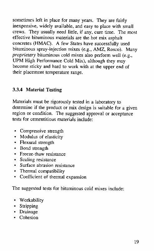
sometimes left in place for many years. They are fairlyinexpensive, widely available, and easy to place with smallcrews. They usually need little, if any, cure time. The mosteffective bituminous materials are the hot mix asphaltconcretes (HMAC). A few States have successfully usedbituminous spray-injection mixes (e.g., AMZ, Rosco). Manyproprietary bituminous cold mixes also perform well (e.g.,UPM High Performance Cold Mix), although they maybecome sticky and hard to work with at the upper end oftheir placement temperature range.
3.3.4 Material Testing
Materials must be rigorously tested in a laboratory todetermine if the product or mix design is suitable for a givenregion or condition. The suggested approval or acceptancetests for cementitious materials include:
• Compressive strength• Modulus of elasticity• Flexural strength• Bond strength• Freeze-thaw resistance• Scaling resistance• Surface abrasion resistance
• Thermal compatibility• Coefficient of thermal expansion
The suggested tests for bituminous cold mixes include:
• Workability• Stripping• Drainage• Cohesion
19

These laboratory tests are index tests and do not necessafi_lypredict performance. Therefore, initial field testing should beconducted. Material safely data sheets should be examined,as well as storage requirements and shelf life.
3.4 Selecting Accessory Materials
Many materials besides the patching materials are used in thepartial-depth spall repair process. Bonding agents, joint bondbreakers, joint sealants, and curing compounds may also berequired. This section provides guidance in selecting theseaccessory materials.
3.4.1 Bonding Agents
Different bonding agents require varying cure periods.Therefore, the bonding agent should be selected after therepair material has been chosen and the time-to-traffic hasbeen determined. Not all patching materials need a bondingagent. The manufacturer's recommendation should always befollowed. Epoxy bonding agents should be used with TypeIII PCC materials, as they provide a curing time of 6 hoursor less.
3.4.2 Joint Bond Breakers
Joint bond breakers (polyurethane, polystyrene, orpolyethylene strips, and fiberboards) prevent patches installedat a joint from bonding to the adjacent slab. Joint bondbreakers must be nonabsorbent, closed cell, chemically inert,
compressible with good compression recovery, andcompatible with the joint sealant. Bond breakers used withhot-poured sealants must be heat resistant for the installation
2O

temperature of the sealant. Section 4.5 describes how toinstall joint bond breakers.
Joint bond breakers that have been scored at an appropriatedepth before placement, as shown in figure 2, arerecommended, as they save time and labor. Once the scoredbond breaker has been placed in the clean joint, and thepatch has been installed and has cured or set, the top strip isremoved. This provides a clean surface and a pre-formedjoint reservoir that is ready for the installation of the jointsealant. Fiberboard is more rigid than other types of bondbreakers. It should be used at the lane-shoulder joint wheremore support is needed.
For information on selecting dimensions for the jointreservoir (the width of the joint bond breaker, and the depthof scoring) consult the Materials and Procedures for Repairof Joint Seals in Concrete Pavements-Manual of Practice. _5
3.4.3 Curing Materials
Water loss during curing causes the patch volume todecrease. This can lead to shrinkage cracks and poor bond.Therefore, curing methods that reduce water loss should beused. The recommended moist curing methods are:
• Water curingcontinuous water spraying
- saturated coverings (burlap, sand, or straw)
• Sealed curingplastic sheetingcuring compounds
21

Figure 2. Scored joint bond breaker
Water curing supplies additional water and prevents moistureloss. Continuous water spraying works well only when waterand labor are plentiful and runoff is not a problem.Furthermore, vigorous spraying can erode the patch.Saturated coverings need periodic wetting, but may provideinsulation in winter if topped with a dry layer. Potable waterthat is clean and free of oil, salt, and other contaminantsmust be used when water curing.
Sealed curing does not add water to the patch, but doesprevent moisture loss when uniformly and adequatelyapplied. Pigmented, liquid, membrane-forming curingcompounds are popular because their opaque color shows ifthey have been adequately applied, they can reflect or absorbsunlight, and they do not blow away. They also do notrequire rewetting or large amounts of water on theconstruction site.
Curing compounds can interfere with bonding between theoverlay and the patch. However, unless the patch is large,such as a full lane-width patch, the effect on bonding shouldnot be that great. A large patch can be cleaned before
22

overlaying if the curing compound has not already worn off.Curing compounds should not be used in the fall, if the patchwill soon be exposed to de-icing salts. Curing compoundsshould be white in color in hot weather, and gray or black incold weather.
3.4.4 Joint Sealants
An appropriate joint sealant must be installed to ensure theperformance of the partial-depth patch. The sealant mustprevent water and incompressibles from entering the joint. Ifthe pavement will not be overlaid and the remaining life ofthe pavement is expected to be long, silicones and highquality hot-poured rubberized or polymerized asphalt sealantsare generally recommended. If the pavement will beoverlaid, the joints should still be filled, but lower qualitymaterials may be acceptable. For information on selecting ajoint sealant consult the Materials and Procedures for Repairof Joint Seals in Concrete Pavements-Manual of Practice. 15
3.5 Selecting Dimensions of the Repair Area
Partial-depth patches should be limited in depth to the topthird of the slab and should never come in contact with
dowel bars. If dowel bars are reached, a full-depth spallrepair must be used. Partial-depth patches must be at least2 in (51 mm) deep for weight and volume stability. Theyshould extend 2 in to 6 in (51 mm to 152 mm) in eachpossible direction beyond the spalled area, and be at least 4in (102 mm) wide and I0 in (254 ram) long. Table 3 showsthe minimum dimensions for patches in various locations.Figures 3 and 4 show the minimum dimensions of partialdepth patches located at one joint; figures 5 and 6, at twojoints.
23

Table 3. Minimum dimensions of repair area for spaHs atvarious locations
Location Minimum dimensions of repair ,areaof
spallingDepth 1 Length I Width _
(in) (in) (in)
at one 2 I0 or length of 4 or width ofjoint spalled area + 4 spalled area + 2
whichever is greater whichever is greater
at two 2 8 or length of 4 or width ofjoints spalled area + 2 spaUed area + 2
whichever is greater whichever is greater
away 10 or length of 5.5 or width offrom 2 spalled area + 4 spalled area + 4
joints whichever is greater whichever is greater
1 in = 25.4 mm.
Areas less than 6 in (152 mm) long or 1.5 in (38 mm) wideare normally not patched, but are filled with a sealant.Patches less than 1 ft (305 mm) from each other should berepaired with one patch, as shown in figures 4 and 6. Whenseveral small spalls exist at one joint, it usually costs less topatch the entire joint length than to repair individual spalls.
In the early stages of spalling, there are often weak areas inthe slab that cannot be seen. The extent of deterioration
should be determined by sounding-striking the concrete witha solid steel rod, chain, or ball peen hammer and listening tothe sound produced. A clear ringing sound indicates soundconcrete, while a dull sound indicates weak concrete. Allweak concrete must be located and included within the patchboundaries.
24

pavement _ patch
-- 2 in (min.) to 6 in
4 in (min.)
Plan View
i!i! iii'"iiiiiii!iiiiiiiiiiii __iiiiiiiiiiiiiiiiiiii ._
...ii iiii!i iiiiii i ii i ii iiiiiiii!iiiiiiiiiiiiiiii..iiiiiiiiiiiiiiiiiiii
Profile View
Figure3. Dimensionsofpatchatonejoint.I in= 25.4mm
25

iiiiiiiillpavement _ patch spall
2 in (min.) ---3to 6 in iiiiiiiiiii:__ iiiiii iiiiiiiiii!iiiii[[iiiiiiiiiiiiiiliiiiii
liiiiiiiiiiii iiiiiiii
i i :ii::_;:;_iiiiiiiiiiiiiiiiiiiiiiiiiiiiiiiii!iiF_iiii !i::::::::::::::: ::::::::::::::::::::::: ................. i!_!!:i_!_;;
4 in (min.)
Plan View
2 in (min.) to T/3 (max.) //
iiiiiiii--]f!i!ii iiiii!
" iiiiiii!
Profile View
Figure 4. Dimensions of patch at one joint for spalls lessthan 12 in apart. 1 in = 25.4 mm
26

iiiiiiiiiipavement _ patch spall
--2 in (min.) to 6 in
iii!!ili#!#::::_:/___._ !iiii
ilill::::::ii::iiiii::iiiii':' _i!ii!i!!i!iiiiii!iiii::iii::i::i::::::ii::iiiiiiiii_liiiiiiiiiiiii
4 in (min.)
Plan View
2 in (min.) to T/3 (max.)
II
Profile View
Figure 5. Dimensions of patch at two joints.1 in = 25.4 mm
27

iiiiiii!iipavement patch spall
2 in (min.) lk: ., .
to6 iiiiiiiiiiiiiiiiiiiiiiiiii_.s_o._._}..ii0..._i_ni;_).0i._iiiiiin iii!!iiiiiii!iiiiiiiiiiiii._!iiiiiiiiiiiiiiiiiiiiiiiiii!!iiiiii!iiiiiiii!!iiii!!iiiiiiii!iiiiiii.
iliii i.o_iiiiiiiii_,'?,!
m giiigg_iiiiiii
i::ili!i_!ii! !!!!:.ii!!!!!!!ii!!!!!!:.!!!!!!!!!_!_!_!_iiiiii_iiiiiiiiiiiii!!l_!i_iiiii_igiiiig_igiiiiig_iiigiiigiiii_ii......._i_iggiii[ii
4 in (min.)
Plan View
iiiiiiiiiii!iiiiiii!iiiiiii!iiiiiii!iiiiii!iiiiiiiiiiiiiiiiiiiiiiii!iiiiiiiiiiiiiii!iiiiiiiiiiiiil.ii!iiiiiiiiiiiiiii!iiiiiiiiiiiiiiiiiiiiiiiiiiiiiiiiiiiiiiiil......................_iiiiiii_iiiii_i
, iiiiiii............................................................!Profile View
Figure 6. Dimensions of paten at two joints for spalls lessthan 12 in apart. 1 in = 25.4 mm
28

3.6 Selecting Patch Preparation Procedures
The patch preparation procedures discussed in this manualinclude the saw-and-patch procedure, the chip-and-patchprocedure, the mill-and-patch procedure, the waterblast-and-patch procedure, and the clean-and-patch procedure. Theonly difference between these patch preparation procedures isthe method used to remove the deteriorated concrete.
Sandblasting and airblasting are highly recommended for allpreparation procedures, though they may be impractical underadverse conditions.
When selecting a procedure, the highway agency shouldconsider equipment availability and cost, the availability of acrew trained in the procedure, the available construction time,and the cost-effectiveness of the procedure. Section 3.8provides guidelines for determining cost-effectiveness.
3.6.1 Saw and Patch
The first step in the saw-and-patch procedure is sawing thepatch boundaries with a diamond blade saw. Thedeteriorated concrete in the center of the patch is thenremoved using a light jackhammer with a maximum weightof 15 lb (6.8 kg); a jackhammer with a maximum weight of30 lb (13.6 kg) may be allowed if damage to sound pavementis avoided. Finally, the deteriorated concrete near the patchborders is removed using a light jackhammer with amaximum weight of 15 lb (6.8 kg) and hand tools. The workshould progress from the inside of the patch toward theedges, and the chisel point should be directed toward theinside of the patch.
The advantages of the saw-and-patch procedure include thefollowing:
29

• The saw leaves vertical edge faces.° The forces experienced by the pavement during chipping
are isolated within the sawed boundaries.
• Very little spalling of the remaining pavement occurs.• Removing the deteriorated concrete within the sawed
boundaries is usually easier and faster when theboundaries are sawed than when they are not sawed.
• Most crews are familiar with the method.
The disadvantages of the saw-and-patch procedure includethe following:
• More workers are required than in the other procedures.• Since water is used when sawing, the repair area is
saturated for some time, possibly delaying the repair.• Saw overcuts weaken the repair area and must be cleaned
and sealed.
• The saw may encroach into the open lane of traffic.• The polished, vertical patch boundary faces may lead to
poor bonding.
If the patching material is moisture-sensitive and will notbond to a wet surface, placement must be delayed. This canbe avoided by sawing joints and boundaries 1 to 2 daysbefore removing and replacing the material. (Sawed edgesdo not spall when traffic is allowed onto repair areas thathave been cut 1 to 2 days in advance.) However, if moreunsound concrete is later found beyond the sawedboundaries, the saw must be brought back to saw newboundaries, possibly causing further delay. Also, the sawmay encroach into the open lane of traffic if the spall is nearthe open lane, creating a hazardous situation.
Saw overcuts occur because the boundaries must be overcut 2in to 3 in (51 mm to 76 ram) in each direction to obtain theneeded depth of cut. These overcuts create weak areas thatmay deteriorate unless cleaned and sealed.
3O
3.6.2 Chip and Patch
The chip-and-patch procedure is the same as the saw-and-patch procedure, except the patch boundaries are not sawed.The deteriorated concrete in the center of the patch isremoved using a light jackhammer with a maximum weightof 15 lb (6.8 kg); however, a jackhammer with a maximumweight of 30 lb (13.6 kg) may be allowed if damage to soundpavement is avoided. The deteriorated concrete near the
patch borders is then removed using a light jackhammer witha maximum weight of 15 lb (6.8 kg) and hand tools. Thework should progress from the inside of the patch toward theedges, and the chisel point should be directed toward theinside of the patch.
The advantages of the chip-and-patch procedure include thefollowing:
• The rough vertical edge produced promotes bonding.• There are no saw overcuts.
• It has fewer steps than the saw-and-patch method.• Spalling is controlled by using light hammers at the edges.• It may be quicker than the saw-and-patch method.
The chip-and-patch procedure may be faster because it hasfewer steps: the patch boundaries are not sawed, and thereare no saw overcuts to be cleaned and sealed. Once jointsawing is completed (see section 4.2.2), the saw is notneeded again, even if more unsound concrete is later foundbeyond the boundaries.
The disadvantages of the chip-and-patch procedure includethe following:
• Sound concrete may be damaged by heavy hammers.• Jackhammers can cause feathered patch edges.• Vertical sides are difficult to achieve.
31

The transmission of destructive forces may be reduced byusing a heavy hammer only at the center of the repair areaand a light hammer around the edges. If the selected repairmaterial should not be feathered (e.g., some cementitiousmaterials), a minimum l-in (25-mm) vertical face on all sidesmust be specified; that is, the top portion of the patchboundaries must be vertical for at least 1 in (25 mm).
3.6.3 Mill and Patch
Some States have successfully used carbide-tipped millingmachines for spall repair, 16 Standard milling machines with12-in to 18-in (305-mm to 457-mm) wide cutting heads haveproven efficient and economical, particularly when used forlarge areas (e.g., for full lane-width repairs). The millingoperation leaves a rounded cavity that may be made verticalby hammering or sawing. The milling machine should havea drurn diameter of 3 ft (0.9 m) or less and make a 12-in(305-mm) wide cut or narrower.
The advantages of the mill-and-patch procedure include thefollowing:
• It is efficient and economical when repairing large areas.• It leaves a rough, irregular surface that promotes bonding.
The disadvantages of the mill-and-patch procedure includethe following:
• If the spall is less than I ft2 (0.09 m2), the patch may belarger than needed, because the smallest milling headcurrently available provides a 1 ft2 (0.09 m2) cut.
• The milling operation may cause spalling on the adjacentpavement edges.
• The milling machine makes a hole with two roundededges (perpendicular to the direction of milling) that
32

should be made vertical by chiseling if they areperpendicular to the direction of traffic.
Some milling machines seem better suited for milling asphaltand than for milling concrete. More powerful equipmentmay increase concrete milling efficiency and reduce spallingof the adjacent pavement.
The orientation of the rounded edges should be parallel to thedirection of traffic whenever possible, as shown in figure 7.However, due to traffic in the adjacent lane, the equipmentmay not always be able to maneuver into such an orientation.The larger the repair areas and the further they are from theadjacent lane of traffic, the higher the efficiency of themilling operation. The efficiency of milling is also affectedby the number of milling teeth that must be replaced per day.
Milling machines are readily available in many regions of theUnited States. However, a suitable machine at a reasonablecost may not be available at a specific project site.
3.6.4 Waterblast and Patch
The waterblast-and-patch procedure uses a high-pressurewater jet to remove the deteriorated concrete. Several Statesare testing this method for repairing pavements. Thewaterblasting machine should be capable of producing astream of water at 15,000 psi to 30,000 psi (100,000 kPa to200,000 kPa) and should be controlled by a mobile robot.The waterblasting equipment must be capable of removingdeteriorated concrete at an acceptable production rate, beunder continuous automatic control, and have filtering andpumping units operating with a remote-controlled roboticdevice. The noise level must be less than 90 decibels at a
distance of 50 ft (15 m) from either the power pack unit orthe remote robot.
33

a. [] pavement [_ milled area
direction of milling
_i_iii_i_i_iiii_iiiiiii_i_i_i_i_i_!i_i!!_i_iiiiiiiii_i_i_!i_i_i_i_i_i_!i_iiiii!iiiiiiii_i_::_::_::_::_::_i_i_i_i_i_::_::_i_::_i_:;:_::_:_:_i_::_::_::_::_::_::_::_i_::_::_::_:_:_:_:._i_:._i_:._:._i_i_i_:._:._i_.91-- transverse
directio_ jointof traffic concave
Profile View
bo
Figure 7. a. Recommended orientation of milled patch,b. Milled patch with rounded edges
34

The advantages of waterblasting include the following:
• It requires fewer workers than the other procedures.• Once an experienced operator adjusts the operating
parameters, only weak concrete is removed.• The patch surfaces produced are vertical, rough, and
irregular, and enhance bonding.° No hauling is required.
The disadvantages of waterblasting include the following:
• The finished surfaces are saturated. Placement must be
delayed until the area dries unless the repair material isnot moisture-sensitive.
• The fine slurty laitance remaining after the procedurerequires careful attention during cleaning.
• A shield must be built around the repair area to protecttraffic if the patch is next to a lane carrying traffic.
• It can be difficult to control the depth of removal.• Equipment rental is expensive.° It can be difficult to obtain a good production rate;
perfonrmnce of waterblasting equipment has been variable,and waterblasting had to be abandoned in several recentprojects.
Some manufacturers expect a concrete removal rate of 60 ft2(5.6 m2) per hour from their waterblasting equipment. Butproblems with equipment or very tough aggregate (such asgranite) can quickly drop the production rate to as low as7 ft2 to 15 ft2 (0.7 m2 to 1.4 m 2) per hour. The waterblastingequipment must function properly, and the operator must bevery skilled to achieve high production rates.
35

3.6.5 Clean and Patch
Adverse patching conditions consist of an air temperaturebelow 40°F (4°C) and a repair area that is saturated withsurface moisture. Under these conditions, highway agenciesoften use the clean-and-patch procedure to performemergency repairs. Deteriorated and loose concrete isremoved with hand tools and swept away using stiff brooms.Occasionally, a light jackhammer may be used if the spalledarea is large or if the cracked concrete is held tightly inplace. The clean-and-patch procedure should be used only ifa spall is hazardous to highway users and the climate is soadverse that no other procedure can be used.
3.7 Estimating Material, Equipment, and Labor
Estimates of the amount of materials needed will depend onthe size and number of spalls, as well as the type of repairmaterial selected. Many repair materials have a range withinwhich they may be extended with aggregate (e.g., Type IIIPCC, Duracal, Set-45, Five Star HP, Pyrament 505). Othermaterials require that the aggregate be placed in the repairhole before the material itself is applied (e.g., Percol FL,Penatron R/M-3003). Volume yields of these two types ofmaterials will depend on the size and amount of theaggregate used to extend the material. Extending a materialwith aggregate (up to the manufacturer's approved limit) willmake the mix more thermally compatible with the existingpavement and reduce its overall cost. The total volumeneeded to fill all the patches should be estimated, andmaterial manufacturers should be consulted to determine the
necessary amount of materials.
Once a repair material has been chosen, the manufacturer'smaterial specifications should be consulted for equipmentrequirements. Table 4 shows the equipment typically used
36

Table 4. Typical equipment used for the five patchpreparation procedures
Preparation Procedure _
Equipment S Icl MiwIASounding equipment: rod, chain, or ,/ ,/ ¢e ,,¢ j2ball peen hammer
Double-bladed concrete saw for joint ¢e j j jsawing
Single-bladed concrete saw for ¢esawing patch boundaries
15-1b (6.8-kg) jackhammer with air ¢¢ _ _3 !/4
compressor
30-1b (13.6-kg) jackhammer with air ¢,.s 4,5compressor
Stiff brooms for debris removal _¢ ¢¢ ,,¢ ,/ ¢¢
Hand tools (pick axe, etc.) ,/ 4 ¢¢
Truck for hauling removed material ¢¢ v¢ ¢¢ ,g
Waterblasting machine ,¢
Milling machine J
Sandblasting equipment with ,,¢ ,g ¢e ¢¢ ¢¢_directional nozzle, sand, air
compressor
Airblasting equipment with oil and j _¢ j ¢¢ _¢2water filtering capability, aircompressor
1 S = saw ,andpatch, C = chip ,andpatch, M = mill and patch, W =waterblast and patch, and A = adverse-condition clean and patch.2 Sounding, sandblasting, and airbh'tstingmay not be practiced underadverse conditions.
3 To remove rounded edges.4 Jackhammering may be used for large areas, or when the deterioratedconcrete cannot be removed using hand tools.5 15-1b(6.8-kg) jackhwnmers ,are preferred. 30-1b (13.7-kg) hammersshould never be used at patch boundaries.
37

for the five spall preparation procedures that are discussed inthis manual. Table 5 shows the mixing and placementequipment and supplies typically used with some rapid-setting spall repair materials. Table 6 shows the personneltypically used with the five spall preparation procedures.Table 7 shows the personnel typically used for the mixingand placement of some rapid-setting partial-depth spaU repairmaterials.
In certain cases (e.g., the pre-placement of the aggregate withPercol FL or Penatron R/M-3003, and the insertion of thejoint bond breaker), one person can be used for two activitiesthat do not occur at the same time. A supervisor may beneeded to oversee the crews and their operations. Additionalpersonnel may be needed for inspection and traffic control.
3.8 Overall Cost-Effectiveness
Calculating overall cost-effectiveness of a partial-depthpatching operation requires an estimate of the cost ofmaterials, labor, equipment, the expected life of the partial-depth patch when constructed with a particular material andmethod, and user inconvenience. The initial cost ofmaterials, labor, and equipment can be estimated fairly easily.However, the adjustment of all costs to reflect the expectedlife of the given repair requires that the expected life beknown. Calculating user costs is even more difficult.
3.8.1 Cost-Effectiveness Worksheet
This section presents a worksheet that helps calculate the costof a partial-depth spall repair operation. The worksheet asksthe user to enter values and perform calculations in a step-by-step fashion. When worksheets have been completed for
38

Table 5. Typical mixing and placement equipment andsupplies
Typic,'dequipment,-md_ _ _ _Z _ _ _supplies_ - _. _
Potable water/hose/pump ,,¢ J J ,,¢ ,¢ J
Drum mixer _ (6-8 fP) ,/ v¢ ,¢
Mort,u" mixer (3-4 ft3) J J v¢
0.75-in elec. drills & 21- ¢¢3 ¢¢3 ¢¢3 _¢
in stainless steel Jiffymixers
Bonding agent brush/roller ¢¢ ¢¢
Vibrators and/or screeds J ¢¢ ¢¢ ,/ ¢¢
Trowels J ¢¢ ,/ ¢¢ ¢¢ J ,/
Shovels J ,f ,I if ,,¢ j j
Curing compound, ¢¢ J J ¢¢
applicator, burlap, orplastic sheeting 4
Insulating blankets _ J J
Vibratory roller or plate J
IElectric generator 6 J J J J J J .I J J
Grayco Percat 5007 J
Spray-injection machine 8 J
Non-water cleaning solvent ,/ ¢¢ J ¢¢ ¢¢
Compression cylinders/rod ¢¢ J ¢¢ J ¢¢
Slump cone J J J ¢¢ ¢¢
Air meter, rod, water bulb ,,¢
' III = Type III PCC, Dur = Duracal, St45 = Set-45, 5HP = Five Star HP, M64
= MC-64, SPll = SikaPronto 11, Pen = Penatron R/M-3003, Pyr = Pyra.nent 505,
PFL = Percol FL, UPM = UPM High Performance Cold Mix, Spray = Spray-injection Mix. 1 in -_ 25.4 mm.
x .
2 Mixer should have twtce the volume of the amount of material to be mixed.3 Capable of 400-600 rpm.
4 May be used in hot (> 85°F 129°C1), windy (>25 mph [40 kph]) weather.
39

Table 6. Typical personnel used for spall repairprocedures
Procedure Typical personnel Total
Joint sawing 1 person operating saw 21 person directing saw
Saw and 1 person operating sawpatch 1 person directing saw
2 persons operating jackhammers 72 persons cleaning repair hole1 person removing debris
Chip and 2 persons operating jackhammerspatch 2 persons cleaning repair hole 5
1 person removing debris
Mill and 1 person operating millingpatch machine
1 person directing milling 7machine
2 persons operating jackhammers2 persons cleaning repair hole1 person removing debris
Waterblast 1 person operating waterblasterand patch 1 person operating water truck 3
1 person cleaning repair hole
Clean and 1 person using hand tools (orpatch jackhammer if necessary) 2
1 person cleaning repair hole
Inserting 1 person installing bond breakerjoint bond (otherwise available for other 1
breaker activities)
40

Table 7. Typical personnel used for mixing and placing
Material Typical personnel I Total [
Type III 2 persons mixing and applying epoxyPCC 1 person proportioning and mixing Type III mix 5
2 persons placing, compacting, and finishing
Duracal 1 person proportioning and mixing Duracal 3
2 persons placing, compacting and finishing
Five Star 1 person proportioning and mixing Five Star HPHP 2 persons placing, compacting, and finishing 4
1 person spraying curing water
Set-45 1 person proportioning and mixing Set-45 3
2 persons placing, compacting and finishing
Pyrament 1 person proportioning and mixing Pyrament 505 3505 2 persons placing, compacting, and finishing
Sika 2 persons mixing and applying SikaPronto 19Pronto I 1 1 person proportioning and mixing SikaPronto 5
11
2 persons placing, compacting, and finishing
MC-64 4 persons mixing MC-64 62 persons placing and finishing
Percol FL 1 person placing rock into prepared hole1 person driving truck with pumps and tanks 41 person applying Percol FL1 person applying broadcast aggregate
Penatron 1 person placing rock into prepared holeR/M-3003 2 persons mixing Penatron R/M-3003 6
3 persons placing and finishing
UPM 2 persons shoveling and placing mixHigh Perf. 1 person operating vibratory roller or plate 3Cold Mix
Spray- 1 person driving truckInjection 1 person operating binder/aggregate sprayer 2Mix
41

different combinations of materials and procedures, they canbe compared to determine which combination is the mostcost-effective.
The cost-effectiveness worksheet is shown in figure 8.Explanations for the variables included in the worksheetfollow.
Project Size or Seasonal Partial-Depth Patching Needs
(A) Expected Number of Patches-The number ofpartial-depth patches (not the number of spalls, asseveral small spalls may be repaired with onepatch) expected in the project or in a given season.This number could be based either on the number
of spalls repaired in the previous season or on afield survey.
(B_) Average Finished Patch Length-The expectedaverage length of the finished patches, in inches.This value could be based either on data from the
previous season or on a field survey where severalpatches throughout the project are sounded todetermine the dimensions of deteriorated area.
This value is helpful in estimating the amount ofrepair materials needed in the project (e.g., bondingagent, curing compound, joint bond breaker, etc.)
5 In weather below 45°F (7"C).As needed; sufficient for demand.
Aft-driven, automatic, ration-metering pump.s Capable of delivering chip-size aggregate and asphalt emulsion (e.g.,AMZ, Rosco).
42

ESTIMATE OF PROJECT SIZE OR SEASONAL PARTIAL-DEPTH PATCHING NEEDS
amount units
Expected Number of Patches (A)Average Finished Patch Length __ in (B 0Average Finished Patch Width __ in (B2)Average Finished Patch Depth __ in (B3)Expected Total Volume of Finished Patches[(B l × B2 x B3 x A) + 46656] yd 3 (C)
MATERIAL COSTS (e.g., cold mix, cement, aggregate, sand, bonding
agent, joint bond breaker, curing agent, etc.)
Material 1 =
Material 1 Purchase Cost __ $/___ (DI)Expected Material 1 Needs (El)Material 1 Shipping Cost __ $ (F0Total Material 1 Cost [(D l X E_) + Ft] __ $ (G_)
Material 2 =
Material 2 Purchase Cost __ $/__ (D2)Expected Material 2 Needs (E2)Material 2 Shipping Cost __ $ (F2)Total Material 2 Cost [(D: x E2) + F2] __ $ (G2)
Material 3 =
Material 3 Purchase Cost __ $/__ (D3)Expected Material 3 Needs (E3)Material 3 Shipping Cost __ $ (F3)Total Material 3 Cost [(D3 x E3) + F3] __ $ (G3)
Material 4 =
Material 4 Purchase Cost __ $/__ (D4)Expected Material 4 Needs (E4)Material 4 Shipping Cost __ $ ([:4)Total Material 4 Cost [(D4 x E4) + F4] __ $ (G4)
Figure 8. Cost-effectiveness worksheet
43

LABOR COSTSmnount units
Number in Repair Crew (H)Average Daily Wage per Person S/day (I)
Number in Traffic Control Crew (J)
Average Daily Wage per Person S/day (K)
Supervisor D_dly Wage S/day (L)
EQUIPMENT COSTS
MateriM Truck S/day (M)
Tr,'dfic Control Truck ,and Signs S/day (N)
Patch Preparation Equipment(e.g., concrete saw, jackh_unmer, S/day (O1)milling machine, waterblaster) S/day (02)
Cleaning Equipment S/day (P1)(e.g., sandblaster, ,'drbl,'tster) S/day (P2)
Mixing Equipment S/day (Q1)(e.g., mortar mixer, Jiffy mixer) S/day (Q2)
Consolidation/Compaction Equipment(e.g., pencil vibrator, vibratingscreed, vibratory roller) S/day (R)
Extra Equipment Truck S/day (S)
Miscell,'meous Equipment S/day (T 1)
(e.g., spray-injection machine, S/day (T2)joint sealing equipment, etc.)
Figure 8. Cost-effectiveness worksheet (continued)
44
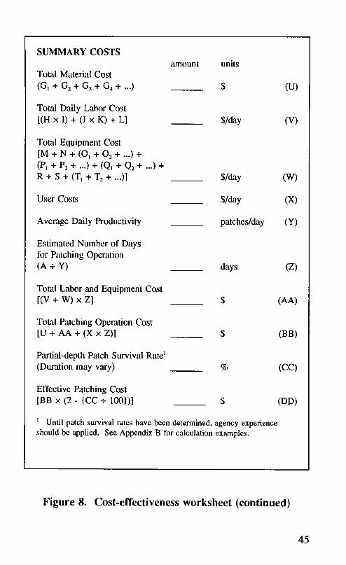
SUMMARY COSTS
amount unitsTotal MateriM Cost
(G1 + G2 + G3 + G4 + ...) $ (U)
Total Daily Labor Cost
[(H x I) + (J x K) + L] S/day (V)
TotM Equipment Cost[M + N + (O 1 + O2 + ...) +
(P1 + P2 + .-.) + (Q1 + Q2 + .-.) +R + S + (T1 + T2 + ...)] S/day (W)
User Costs S/day (X)
Average Daily Productivity patches/day (Y)
Estimated Number of Daysfor Patching Operation
(A + Y) days (Z)
Total Labor ,and Equipment Cost
[(v + w) x z] $ (AA)
Total Patching Operation Cost[U + AA + (X x Z)] $ (BB)
Partial-depth Patch Survival Rate 1(Duration may vary) % (CC)
Effective Patching Cost
[BB x (2 - {CC + 100})] $ (DD)
] Until patch survival rates have been determined, agency experienceshould be applied. See Appendix B for calculation examples.
Figure 8. Cost-effectiveness worksheet (continued)
45

(B2) Average Finished Patch Width-The expectedaverage width of the finished patches, in inches.This value could be based either on data from the
previous season or on a field survey where severalpatches throughout the project are sounded todetermine the dimensions of the deteriorated area.
This value is helpful in estimating the amount ofrepair materials needed in the project (e.g., bondingagent, curing compound, joint bond breaker, etc.)
(B3) Average Finished Patch Depth-The expectedaverage depth of the finished patches, in inches.This value could be based either on data from the
previous season or on a field survey where severalpatches in the project are sounded and cored todetermine the depth of the deteriorated area. Thisvalue is helpful in estimating the necessary depthof the joint bond breaker or fiberboard.
(C) Expected Total Volume of Finished Patches-Theestimated total in-place volume of material neededto fill the patches, in cubic yards, based on theestimated average length (Bi), width (B2), anddepth (B3). This value could be based either on theprevious season's data or on the results of a fieldsurvey. This value is helpful in estimating theamount of material components needed for the
project (e.g., cold mix, cement, aggregate, sand,etc.)
Material Cost Variables
(D,) Material Purchase Cost-The cost of purchasingeach material used to repair the partial-depth spalls.Materials will include the patching material, andpossibly a material such as a bonding agent, joint
46

bond breaker, or curing compound. This cost doesnot include shipping costs. The amount should beentered in dollars per ton, yd 3, gal, yd, etc., asappropriate for each material. If there are morethan four materials, the worksheet can beduplicated.
(En) Expected Material Needs-The amount of eachmaterial needed for the project, such as the amountof the patching material, bonding agent, joint bondbreaker, or curing compound, taking intoconsideration a wastage factor of 10 to 20 percent.The amount should be entered in units of ton, yd3,gal, yd, etc., as appropriate for each material.
(Fn) Material Shipping Cost-The cost of shipping eachmaterial from the site of production to the site ofstorage during the project, in dollars.
(G,) Total Material Cost-The total cost of eachmaterial including shipping, in dollars.
Labor and Equipment Costs Worksheet Vatqables
(H) Number in Repair Crew-The number of workerswho will be performing the partial-depth patchingoperation, not including traffic control personnel.
(I) Average Daily Wage per Person-The averagewage paid to the members of the repair crew, indollars per day. By multiplying this figure by (H),the total labor costs for the workers doing thepatching can be obtained.
(J) Number in Traffic Control Crew-The number of
workers required to set up and conduct the traffic
47

control operation. When the repair crew sets upsigns and cones before the repair operation, thenumber of traffic control workers would be zero, sothat the workers are not counted twice,
(K_ Average Daily Wage pen"Person-The averagewage paid to the members of the traffic controlcrew, in dollars per day. By multiplying thisnumber by (J), the total labor costs for the workersdoing the traffic control can be obtained.
(L) Supervisor Daily Wage-The wage paid to thesupervisor who oversees the repair operation, indollars per day.
(M) Material Truck-The operating charge associatedwith the truck carrying the repair materials(excluding the driver's wages), in dollars per day.Only trucks carrying the repair material should beincluded.
(N) Traffic Control Truck and Signs-The costassociated with all traffic control, including thecost of arrow boards, attenuator trucks, etc., in
dollars per day. If vehicles are used to set uptraffic control and then are used for other activities
during the day, a fraction of the daily cost shouldbe used to approximate the time spent setting uptraffic control for the repair operation. The amountentered should not include the cost of labor.
(On) Patch Preparation Equipment-The costassociated with each piece of equipment that isused to saw the patch boundaries and/or to removethe deteriorated concrete (e.g., concrete saw,jackhammers, milling machine, waterblastingmachine, etc.), in dollars per day.
48

(P.) Cleaning Equipment-The cost associated witheach piece of equipment used to clean the repairhole after the deteriorated concrete has been
removed, in dollars per day. If a spray-injectionmachine's air hose is used to clean the repair hole,this value should be zero_
(Q_) Mixing Equipment-The cost associated with each
piece of equipment used to mix the repairmaterial(s), in dollars per day.
(R) Consolidation/Compaction Equipment-The costassociated with the equipment used to consolidateor compact the patches, in dollars per day.
(S) Extra Equipment Truck-The cost associated withany equipment used to transport preparation,cleaning, mixing, consolidation, or compactionequipment to the site, in dollars per day.
(T.) Miscellaneous Equipment-The cost associatedwith each piece of any other equipment used in thepartial-depth spall repair process that was notincluded in (M) through (S) (e.g., spray-injectionmachine, joint-sealing equipment, etc.), in dollarsper day.
Summary Costs
(U) Total Material Cost-The cost of all materials usedin the partial-depth spall repair process, in dollars.
(V) Total Daily Labor Cost-The cost per day of alllabor used in the partial-depth spall repair process,in dollars per day.
49

(W) Total Equipment Cost-The cost per day of allequipment used in the partial-depth spall repairprocess, in dollars per day.
(X) User Costs-The costs to the highway user per daydue to the delay associated with the repairoperation, in dollars per day. This value is fairlydifficult to calculate; the agency may rely on itsexperience.
(Y) Average Daily Productivity-The rate at which thepartial-depth spall repair patching can be done bythe patching crew, in patches per day. Thisamount should reflect the size and experience ofthe crew specified above.
(Z) Estimated Number of Days for PatchingOperation-An estimate of the number of daysrequired to perform the partial-depth spall repairs.
(AA) Total Labor and Equipment Cost-The cost oflabor and equipment for the duration of the partial-depth spall repair process, in dollars.
(BB) Total Patching Operation Cost-The total initialcost of the entire partial-depth repair process, indollars. It does not take into account the expectedlife of the partial-depth patches. To compare thecost-effectiveness of different material and
procedure combinations without knowing thepartial-depth patch survival rate, the costs perproject or season of using each one can becompared.
(CC) Partial-Depth Patch Survival Rate-An estimateof the number of patches that will survive for aspecific duration. The amount entered should be in
5O

percent. To compare the cost effectiveness ofdifferent material and procedure combinations, theuser must enter percent survival for each using thesame time period (i.e., 1 year, 5 years, I0 years)for each material and procedure combination.
(DD) Effective Patching Cost-The cost of partial-depthpatching, in dollars, adjusted to reflect the expectedlife of the partial-depth patches.
3.8.2 Determining Cost-Effectiveness Inputs
The cost-effectiveness analysis requires an evaluation of themaintenance crew, their past efficiency, their current salarylevels, and the availability of equipment. The costs ofmaterials, shipping, and rental equipment may be obtainedfrom manufacturers and dealers such as those listed in
Appendix E. It is difficult to obtain accurate user costs andpartial-depth patch survival rate for a given material andprocedure. Pavement condition, material quality, climaticconditions, and crew ability all factor into these values.Guidelines for calculating patch survival rates are given inChapter 5; examples of patch survival rate calculation areincluded in Appendix B.
51

4.0 Construction
The most frequent construction-related causes of partial-depthpatch failure include the following:
• Failure to square the hole• Failure to remove all deteriorated material
• Inadequate cleaning° Lack of bond
• Failure to re-establish the joint (compression failure)• Variability of the repair material• Insufficient consolidation
This chapter provides guidelines for each step in theconstruction process to help eliminate these causes of failure.The topics covered include: traffic control, safety precautions,materials testing, joint preparation, patch preparation, mixingthe repair materials, placing the repair materials,consolidating and compacting, screeding and finishing,curing, joint sealing, cleaning up, opening to traffic, andinspection of the construction process.
4.1 Traffic Control
Whenever any partial-depth patching operation is performed,it is very important to provide adequate traffic control. Thisensures a safe working environment for the maintenance crewand safe travel for vehicles in the construction area. Traffic
control operations should cause the least possible amount ofdisturbance in the flow of traffic. While the actual traffic
control requirements for each construction site will vary,every maintenance agency has the responsibility of ensuringthat all necessary steps are taken to maintain safety.
53

4.2 Safety Precautions
Many rapid-setting materials require special safetyprecautions, both to protect the maintenance workers usingthem and to protect the environment. It is extremelyimportant that highway agencies follow all instructionsregarding worker protection and repair material disposal.These instructions are available from the manufacturer in
the form of material safety data sheets.
In addition, the agency should follow safety instructions forworker protection and material disposal for any otheraccessory material or substance used (e.g., solvents, bondingagents, joint bond breakers, admixtures, curing compounds,etc.), as well as for all equipment that is used in the partial-depth spall repair process.
Some common-sense safety precautions for using materialsand equipment in the partial-depth spall repair process areincluded in Appendix C.
4.3 Material Testing
Material testing during the construction phase of a partial-depth spall repair project involves daily quality control. Aprogram of testing samples of the repair mix for slump, air,compressive strength, or flexural strength should beconducted, as appropriate, for each type of cementitiousrepair material. Testing of bituminous and flexible polymerrepair materials must be done before their use in the field.Appendix A outlines suggested pre-construction materialtesting specifications.
54

4.4 Initial Joint Preparation
The most frequent cause of failure of partial-depth spallrepairs is high compressive stress. Nonflexible partial-depthpatches placed directly against transverse joints and crackswill be crushed by the compressive forces created when thereis not enough room for thermal expansion of the slabs.Patches may also fail if, during placement, the repair materialis allowed to flow into the joint or crack opening below thebottom of the patch. When cured, the material will preventthe crack or joint from working and will keep the slabs frommoving. These failures must be prevented by using properjoint preparation methods.
4.4.1 Removing Old Sealant
If a nonflexible patching material is used, the old sealant inthe adjacent joint and 3 in to 4 in (76 mm to 102 mm)beyond the patch must be removed for placement of a jointbond breaker. If a flexible polymer material is used, the oldsealant should still be removed, and the area adjacent to thepatch should be cleaned thoroughly. Bituminous materials donot need any special cleaning.
Most spall repair materials are nonflexible. However, somematerials (e.g., some polymers, cold mixes, spray-injectionmixes) are flexible and do not need a joint sealant or a jointbond breaker. The rnaterial manufacturer should be
consulted to determine if joint sealant or bond breakers arenecessary.
55
4.4.2 Joint Sawing
When a joint bond breaker is needed, the existing transverseand longitudinal joints next to the repair should be resawnusing a double-bladed concrete saw. The depth of the cutshould be at least 1 in (25 mm) deeper than the depth of therepair. The saw cut should extend 2 in to 3 in (51 in to 76mm) beyond the repair area in each direction. This sawing isusually done before removing the deteriorated concrete, andmust be done before cleaning the repair area. Figure 9shows the proper dimensions of the saw cut. Water-washequipment should be used to remove all sawing slurry fromthe repair area before it dries.
Joint sawing may not be needed if flexible materials, such asPercol FL and Penatron R/M-3003, are used. Joint sawing isnot used either in the clean-and-patch procedure because ofadverse conditions or when UPM High Performance ColdMix and spray-injection mix (e.g., AMZ, Rosco) are used.
Repairs can be constructed without transverse joint bondbreakers by sawing the transverse joint to full depth as soonas the patch has gained sufficient strength. However, if thejoint closes before sawing, the patch will fracture. Thisoperation is not recommended because timing is critical.
4.4.3 Sawing Out Joint Inserts
Spalls caused by metal or plastic joint inserts usually start atthe bottom fin of the insert, about 2.5 in (64 mm) below thesurface. When repairing this type of spall, the joint insertshould be sawed out along the entire length of the joint toprevent further deterioration. The joint can then be repairedand resealed. This is normally done using a double-bladedconcrete saw, before removing the deteriorated concrete.
56

iiiiii_ iiiiiiiiiiiiiiiiiiii_iii_:' ...........".........................iiiiiiiiiii_
fill!i!! _ !iiiill
joint saw cut
iiiiii!!!!!!...........................................i[iiiii!i!ii ii!!ii!ipavement
iiiiiiil ii_ ii iiiiiiiiiiill _ area to be removedPlan View spall
iii!iiiiiiJ iii j_!i_iiii_iiii!i!!!!!!!!!iliiiiii!iiii_iiiiiiiiiiiiii!iiiiiiiii!i!iiiiiiii
Profile View
Figure 9. Dimensions of joint saw cut
4.5 Removing the Deteriorated Concrete
Partial-depth removal of the deteriorated concrete may bedone using several methods. The most frequently usedmethod, the saw-and-patch procedure, uses a wheel saw to
57

cut the patch boundaries, and jackhammers to remove theconcrete inside the boundaries. Small hand-held saws are
occasionally used, but wheel saws are more common. Othermethods include chiseling without sawing the patchboundaries, cold milling, waterblasting, and using hand tools(under adverse conditions).
4.5.1 Saw and Patch
In the saw-and-patch procedure, a single-bladed concrete sawis used to cut the boundaries of the patch and to makeremoving the deteriorated concrete easier, as shown in figure10. The saw cut should be 1 in to 2 in (25 mm to 51 mm)
deep and usually extends 2 in to 3 in (51 mm to 76 mm)beyond the patch boundaries, to obtain that depth for theentire length and width of the patch. The cut boundaryshould have straight, vertical faces and square corners.Vertical boundaries reduce the spalling associated with thinor feathered concrete along the repair perimeter. Therecommended dimensions of the repair boundaries are shownin figures 3 through 6. For large areas of repair, the area tobe removed may be sawed in a shallow criss-cross or wafflepattern to facilitate concrete removal, as shown in figure 11.Water-wash equipment should be used to remove sawingslurry from the repair area before it dries.
After sawing, jack hammers are used to remove the unsoundconcrete. Initially hammers weighing less than 15 lb (6.8 kg)are used, but hammers weighing up to a maximum of 30 lb(13.6 kg) may be allowed. Removal should begin near thecenter of the spall and proceed toward (but not to) the patchboundary. Care must be taken not to fracture the soundconcrete below the repair or to overcut the repair boundaries.
Removal near the repair boundaries must be completed with10-1b to 15-1b (4.6-kg to 6.8-kg) hammers fitted with spade
58

bits, as gouge bits can damage sound concrete. Spade bitsare shown in figure 12. Jackhammers and mechanicalchipping tools should be operated at an angle less than 45degrees from the vertical as shown in figure 13.
Finally, the repair area must be tested again for soundnessafter removing the deteriorated concrete as shown in figure14. Any additional unsound concrete must be removed bycontinued chipping. A full-depth repair must be used if thedeterioration is found to be deeper than the top third of thepavement slab, or if reinforcing bars or mesh are reached.
59

iiiiiiii!iiiiiiiiiltiiiiiiiiiiiiiiiiiiiiiiiiiiiiii!iiiiiiiiii!iiiiiiiii!!!iii
!iiiiiiiiiiiiiili pavementiiiii!!iiiiiiii!iiiiiiiiiii!!iiiiill _ areatobe
ii!iii!ii!iiiiiii! remo,eiiiiiiiii!iiiiiii!
Figure 11. Sawing pattern for large repair areas
4.5.2 Chip and Patch
The chip-and-patch procedure is the same as the saw-and-patch procedure, except that the patch boundaries are notsawed. Cutting boundaries with jackhammers may result inscalloped boundaries. Therefore, a 1-in vertical edge must bespecified when using a repair material that does not performwell when feathered. A scalloped edge and a 1-in (25-ram)vertical edge are shown in figure 15.
Finally, the repair area must be tested again for soundness, asshown in figure 14. Any additional unsound concrete mustbe removed by continued chipping. A full-depth repair mustbe used if the deterioration is found to be deeper than the topthird of the pavement slab, or if reinforcing bars or mesh arereached.
60

Front View Side View
Figure 12. Spade bits
•_ :" :""
".H .H.::/I_ H.:I_/
Figure 13. Using a jackhammer
61

ii:_:::::iiil ,
..... :.::.._:!:'_l:_:::::::...::::: ................
Figure 14. Sounding repair area with a steel rod
!!!iii!ipavement _ repairareaiiiiiiiiia ::::::::::::::::::::::::::::::: ::::::::::::::::::::::::::::::::::::::::::
'"'"'.......i[jiiiiiiiiiiiiiyy ijiFiii!iliiiiiiiPlan View Plan View
i!l_iiiiiiiiiiiiii!!l_iiiiiiiiProfile View Profile View
scalloped edge 1-in vertical edge
Figure 15. Scalloped edge and 1-in vertical edge
62

4.5.3 Mill and Patch
In the mill-and-patch procedure, all unsound concrete withinthe marked area is removed to a minimum depth of 2 in (51mm) using a carbide-tipped milling machine. The smallamount of material that remains at the patch comers must beremoved by light jackhammering or sawing. Wheneverpossible, the milling machine should be oriented such that therounded edges of the hole it produces are parallel to thedirection of traffic. The proper orientation of the roundededges of the milled patch is shown in figure 7. If thisorientation is not possible, the rounded edges should be madevertical using a light jackhammer.
Finally, the repair area must be tested again for soundness, asshown in figure 14. Any additional unsound concrete mustbe removed by continued milling. A full-depth repair mustbe used if the deterioration is found to be deeper than the topthird of the pavement slab, or if reinforcing bars or mesh arereached.
4.5.4 Waterblast and Patch
The first step in the waterblast-and-patch procedure is tobuild a shield around the repair area if there is any trafficpassing in the next lane, as shown in figure 16. Two trialareas, one of sound concrete and one of deteriorated concrete,are then used to determine the appropriate waterblastingoperating parameters. These parameters include speed,pressure, and the number of overlapping passes. Using trialand error in the test areas, the waterblaster must beprogrammed to remove all unsound concrete withoutremoving sound concrete unnecessarily.
Once properly calibrated, the operating parameters should notbe changed while waterblasting the rest of the spalls, unless
63
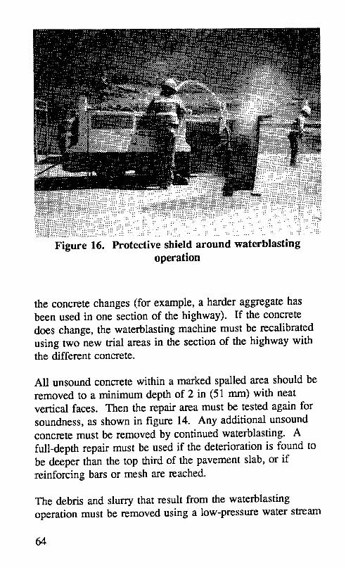
the concrete changes (for example, a harder aggregate hasbeen used in one section of the highway). If the concretedoes change, the waterblasting machine must be recalibratedusing two new trial areas in the section of the highway withthe different concrete.
All unsound concrete within a marked spalled area should beremoved to a minimum depth of 2 in (51 mm) with neatvertical faces. Then the repair area must be tested again forsoundness, as shown in figure 14. Any additional unsoundconcrete must be removed by continued waterblasting. Afull-depth repair must be used if the deterioration is found tobe deeper than the top third of the pavement slab, or ifreinforcing bars or mesh are reached.
The debris and slurry that result from the waterblastingoperation must be removed using a low-pressure water stream
64

before the slurry dries and hardens on the surface of the hole.If this is not done, the repair area may have to be refaced.Once dried, sandblasting may or may not be able to removethe dried slurry residue. Some moisture-sensitive materialsmay require the repair area be completely dry before placingthe material.
4.5.5 Clean and Patch
Under adverse conditions, handpicks and shovels should beused to remove loose material. A light jackhammer maysometimes be used for larger areas.
4.6 Cleaning the Repair Area
After all unsound concrete has been removed, the surface of
the repair area must be cleaned. Sandblasting, airblasting,and sweeping normally provide a clean, rough surface for thedevelopment of a good bond between the patch and thepavement. High-pressure water may also be used to removedirt, dust, and other contaminants, but sandblasting usuallyproduces better results.
4.6.1 Sandblasting
Sandblasting, shown in figure 17, is highly recommended forcleaning the surface. It removes dirt, oil, thin layers ofunsound concrete, and laitance. Sandblasting equipmentconsists of a compressed air unit, a sand dispenser, hoses,and a wand with a venturi-type nozzle. The compressed airmust be free of oil and water, since a contaminated surfacewill prevent bonding. The air quality can be checked byplacing a cloth over the air compressor nozzle and visually
65
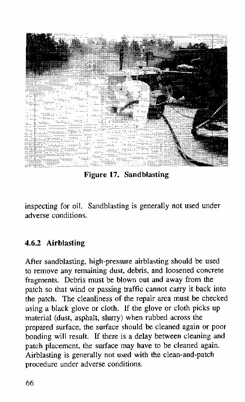
• . .... _: _:_i.i_::_::_::::..::..:::::::.:::::.:
iiiiiiiiiii_:?:_::!_:_:_i!_iiiiiiiii!!iiiiii__ ! ::!:iii!i:i!!:ii::!:: : _ __:_:
:_.::.l_.:::-_:iiiiiiiiiiiiiii__-i _!iiiiiiiiiiiiiii_
Figure 17. Sandblasting
inspecting for oil. Sandblasting is generally not used underadverse conditions.
4.6.2 Airblasting
After sandblasting, high-pressure airblasting should be usedto remove any remaining dust, debris, and loosened concretefragments. Debris must be blown out and away from thepatch so that wind or passing traffic cannot carry it back intothe patch. The cleanliness of the repair area must be checkedusing a black glove or cloth. If the glove or cloth picks upmaterial (dust, asphalt, slurry) when rubbed across theprepared surface, the surface should be cleaned again or poorbonding will result. If there is a delay between cleaning andpatch placement, the surface may have to be cleaned again.Airblasting is generally not used with the clean-and-patchprocedure under adverse conditions.
66

Either trailer-mounted air compressors or portable back-packblowers may be used. Back-pack blowers need only onelaborer and are very mobile. However, trailer-mounted aircompressors are recommended because they provide a higherpressure (greater than 100 psi [670 kPa]). The compressedair unit should have oil and moisture filters; otherwise, itmay blow oil or moisture into the repair area and prevent thepatch from bonding. When patching with a spray-injectionmachine (e.g., AMZ, Rosco), the hole may be cleaned withits blower.
4.6.3 Sweeping
Sweeping is most commonly used to clean the repair areawhen patching under adverse conditions. Under betterconditions, sandblasting and airblasting should be used.
4.7 Final Joint Preparation
If a nonflexible repair material is used, a compressible jointbond breaker must be installed as the last step of jointpreparation. The type of joint (i.e., transverse, centerline, orlane-shoulder) will determine the type of bond breaker to use.Some flexible materials may not need a bond breaker.
Polystyrene or polyethylene joint bond breakers are placedflush with the pavement surface, between the new(nonflexible) concrete and the adjacent slab to reduce the riskof compression-related failure. They also protect the patchfrom damage caused by deflection under traffic.
The bond breaker should have a scored top strip as shown infigure 2. It should extend 1 in (25 mm) below and 3 in (76ram) beyond the repair boundaries, as shown in figures 18
67

_0_'_
_ _ °_ _
_ °ooo_ _
El @ ..........N
...........................................................iiiiiiil::::::::::::::::::::::::_::::::::::::::::::::::::::::::::::
iii!iiiiiiiiiiiiiiiiiii_iiiiiiiiiiiiii!iiiiiiiiiii!iiiiiil _ _
!iiiiiiiiiiiiiiiiiiiiiiiiiiiiiiiiiiiiiiiiiiiiiiiiiiiiii!iii _ _ _
i i° ::_::::::::::::::
_ i_iiiiiii!iiiiii _
!i!iiiiiiiiiiii_iiii_iii!iiiiiiiiii!i_!i!!!iiiiiiiiiiiiiill .............................. _
::::::::::::::::::::::::::::::::::::::::::::;::::::::::::::: _ ................................
68

and 19. The extension will prevent the repair material fromflowing into the joint during placement. The bond breakershould be slightly wider than the joint so that it is slightlycompressed when installed. The scored top strip must laterbe torn off and the resulting joint reservoir filled with anappropriate joint sealant.
Consult the Materials and Procedures for Repair of JointSeals in Concrete Pavements-Manual of Practice for moreinformation on selecting appropriate dimensions for the jointreservoir and joint bond breaker, and for appropriate jointsealing materials and methods. 15
4.7.1 Preparing Transverse Joints
A straight joint line should be maintained during bondbreaker placement at transverse joints. This may be difficultwith back-to-back patches. Bond breakers of differentheights may be installed in patches of different depths.Alternatively, the bond breaker may be stacked to the neededdepth, which may be difficult. Latex caulking may be usedto seal any gaps between layers of bond breaker or betweenthe bond breaker and the joint opening, as illustrated infigure 19. This will prevent the repair material from flowinginto the joint or a crack opening below the bottom of thepatch.
4.7.2 Preparing Centerline Joints
Partial-depth patches placed at the centerline joint often spallbecause of curling stresses. To prevent this, a polyethylenestrip (or other thin bond-breaker material) must be placedalong the centerline joint to prevent the patch fromcontacting the adjacent lane, as described in section 4.7.1.
69
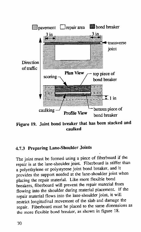
[]pavement [-Trepair area E! bond breaker
..3..i._.. ,3 inii iiiiii'ii',!iiiii',iiiiiiiiii/iiiiiiliiiiiiliiiiiii ii_"::::::::;:;_ wansverse
_ joint
Directionof traffic
scoring--,, Plan View/-- top piece of
bond breakeriiiiiiiiiii!i_iiiiiiiiiii_ii iiiii_:ji_iiii_iii
"i'_:'.:_£:_:i?ij::::ii_ijiiiiih}iiiiiJJii:i_:i}i55i_iiiii_J-Ji"jJj_i'JiiiiSiS"ii-_;.:_:.:.:!'_JJ_ •
:_:_:_:_:__...`._:_*_:_:_*;:_:_:_:_:_:_:_._l lncaii_!i_i!!iiiiii!iiiiiiiiii!!ii!iiiiiiii_iiiiii!i__mpiece of
Profile View bond breaker
Figure 19. Joint bond breaker that has been stacked andcaulked
4.7.3 Preparing Lane-Shoulder Joints
The joint must be formed using a piece of fiberboard if therepair is at the lane-shoulder joint. Fiberboard is stiffer thana polyethylene or polystyrene joint bond breaker, and itprovides the support needed at the lane-shoulder joint whenplacing the repair material. Like more flexible bondbreakers, fiberboard will prevent the repair material fromflowing into the shoulder during material placement. If therepair material flows into the lane-shoulder joint, it willrestrict longitudinal movement of the slab and damage therepair. Fiberboard must be placed to the same dimensions asthe more flexible bond breaker, as shown in figure 18.
7O

4.7.4 Using Flexible Repair Materials
Some proprietary flexible repair materials, such as MC-64,Percol FL, and Penetron R/M-3003, and some bituminousmaterials, such as UPM High Performance Cold Mix andspray-injection mix (e.g. AMZ, Rosco), may have enoughcompressibility to allow joints to move without needing ajoint bond breaker. The manufacturer should be consultedfor the appropriate joint treatment when using a flexible spallrepair material.
4.8 Pre-Placement Inspection of the Repair Area
After cleaning, the repair area should be inspected todetermine if there is any more unsound concrete. If there is,it should be removed, and the repair area should be cleanedagain. Sandblasting should never be used to remove unsoundmaterial.
If the repair area is sound, it should then be inspected forclean, dry, freshly exposed concrete. Any dust remaining onthe pavement surface around the repair area should beremoved by sweeping, especially on windy days or whentraffic passes alongside the repair. If there is a delaybetween cleaning and placing the material, the repair areamust be inspected again at the time of placement, and mustbe cleaned again by airblowing if dirt has blown into it.
4.9 Mixing the Bonding Agent
Some partial-depth patching materials require epoxy orproprietary bonding agents. Epoxy bonding agents should bemixed carefully according to the manufacturer's instructions.
71

An electric drill with a Jiffy mixer may be used to mix thetwo epoxy components for the required time.
Some spall repair materials, such as SikaPronto 11, speci_fy aproprietary bonding agent. The manufacturer's mixinginstructions should be followed exactly to ensure good patchperformance.
4.10 Mixing the Repair Material
The volume of material required for a partial-depth repair isusually small (0.5 ft3 to 2.0 ft3 [0.014 m3 to 0.057 m3]).
Ready-mix trucks and other large equipment cannotefficiently produce small quantities. Small drum orpaddle-type mixers with capacities of 6 ft3 to 8 ft3 (0.17 m 3to 0.23 m3) and Jiffy mixers are often used. Based on trialbatches, repair materials may be weighed and bagged inadvance to make the batching process easier. Prebaggedcement may also be used; aggregate may be weighed using aprecalibrated volume method (i.e., a bucket can be marked byvolume for the appropriate weight). Continuous-feed mixersare also widely used.
Mixing times and water content must be carefully observedfor prepackaged rapid-setting materials. Mixing for a longertime than needed for good blending reduces the already shorttime available for placing and finishing rapid-settingmaterials. Additional water may significantly reduce thestrength of the patch.
4.10.1 Cementitious Concretes
Rapid-setting cementitious materials used in partial-depthspall repair, such as Type III PCC, gypsum-based concrete
72

(e.g., Duracal), magnesium phosphate concrete (e.g., Set-45),and high alumina concrete (e.g., Five Star HP), generally aremixed with small drum or mortar mixers, as shown in figure20.
The proportions of water, aggregate, and cement depend onthe type of material selected. A rapid-setting Type HI PCCmix generally includes an air-entraining agent, anaccelerating agent, and a superplasticizer. In addition to thecement itself, rapid-setting cementitious materials need cleanwater and a manufacturer-specified gradation of aggregate.Some proprietary materials (e.g., Duracal) also need sand.Most cementitious materials require that the water be addedto the running mixer, followed by the aggregate, and then thecement. Warm water may be needed at air temperaturesbelow 55°F (13°C), while icewater may be needed at highertemperatures. The manufacturer's recommendations for
proportions, mixing sequence, and mixing times for eachcomponent should be followed exactly.
4.10.2 Polymer Concretes
Polymer concretes, such as epoxies (e.g., MC-64), methylmethacrylates (e.g., SikaPronto 11), and polyurethanes (e.g.,Percol FL, Penatron R/M-3003), are generally mixed with aJiffy mixer or a mortar mixer, as specified by the materialmanufacturer.
The materials usually consist of two or more premeasuredliquid components, or a liquid component and cementitiouscomponents. The different components are generally mixedseparately and then in combination. Mortar mixers are usedfor mixing large batches of liquid components and for mixingcementitious components with aggregate. Jiffy mixers areused for mixing small batches of liquid components, asshown in figure 21. Liquid mixtures are either mixed with or
73

.. ..... ...
Figure 20. Adding carefully measured components to adrum mixer
poured over a specified gradation of oven-dried aggregate.The manufacturer's recommendations for mixing sequence,component amounts, and mixing times should be followedexactly.
4.10.3 Bituminous Materials
Bituminous cold mixes (e.g., UPM High Performance ColdMix) are generally mixed at a local plant using themanufacturer's mix design. They may also come premixedin drums, buckets, or bags. When patching spalls with aspray-injection machine (e.g., AMZ, Rosco), the machinemixes asphalt emulsion heated to approximately 135°F (57°C)
74

.. :_
• .":....
..: ... .....
i• .: " • . :!"..._!:...:_:.._...._'...:::.._:
•... "._
Figure 21. Using a Jiffy mixer
and aggregate. An experienced operator should carefullycontrol the volume of each component. The asphalt andaggregate are sprayed out under pressure. Care should betaken not to overfill or to spill material outside of the repairarea.
4.11 Applying the Bonding Agent
A bonding agent should be applied after cleaning the repairarea and just before placing PCC repair materials. Themanufacturer's directions must be closely followed whenusing epoxies or other manufactured grouts. The bottom andsides of the repair area must be thoroughly coated bybrushing the grout or epoxy onto the concrete as shown infigure 22. Spraying may be appropriate for large repair
75
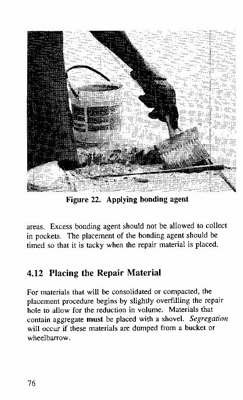
%i!!!iJi!!i!%Figure 22. Applying bonding agent
areas. Excess bonding agent should not be allowed to collect
in pockets. The placement of the bonding agent should betimed so that it is tacky when the repair material is placed.
4.12 Placing the Repair Material
For materials that will be consolidated or compacted, the
placement procedure begins by slightly overfilling the repairhole to allow for the reduction in volume. Materials that
contain aggregate must be placed with a shovel. Segregationwill occur if these materials are dumped from a bucket orwheelbarrow.
76

4.12.1 Cementitious Concretes
PCC and most of the rapid-setting proprietary patchingrnaterials should not be placed when the air or pavementtemperature is below 40°F (4°C). Insulating covers andlonger cure times may be needed at temperatures below 55°F(13°C). The repair area must be sprayed with water toenhance bonding before placing many cementitious materials(e.g., Duracal, Five Star HP, Pyrament 505). Vibration maybe needed during placement to improve workability.
4.12.2 Polymer Concretes
Some polymer concretes may be installed under adverseconditions of low temperatures and wet substrates withreasonable success. _° However, these materials performbetter when installed under more favorable conditions.
Due to their high heat of hydration, some polymer concretes,such as epoxies (e.g., MC-64), and methyl methacrylates(e.g., SikaPronto l 1), are placed in lifts no more than 1.5 to2 in (38 to 51 mm) deep. The time between lifts should bethat recommended by the manufacturer. These materialshave also been placed in one lift during partial-depth spallrepair with no adverse effects.
When placing polyurethane concretes, such as Percol FL andPenatron R/M-3003, the repair area is first filled to gradewith washed, oven-dried, and crushed stone of the type andgradation specified by the manufacturer. The polymer is thenpoured (as in the case of Penatron R/M-3003) or pumped (asin the case of Percol FL) directly over and through thepreplaced aggregate until all the aggregate is encased in theconcrete and the material is flush with the pavement surface,as shown in figure 23. ff specified by the manufacturer,
77

Figure 23. Pumping polymer into a patch that wasprefilled with aggregate
aggregate may then be broadcast over the top of the repair asa friction layer.
4.12.3 Bituminous Materials
Some bituminous mixes may be installed under adverseconditions of low temperatures and wet substrates withreasonable success. 1° However, these materials performbetter when installed under more favorable conditions.
Bituminous cold mixes, such as UPM High PerformanceCold Mix, must be placed by shovel. When patching using aspray-injection machine (e.g., AMZ, Rosco), a coating ofemulsified asphalt should be sprayed into the hole and ontothe edges of the pavement around the repair. A mixture of
78

emulsified asphalt and aggregate should then be sprayeddirectly into the hole. The repair should be filled slightlyabove level with the pavement surface, and a coating of chipstone should be sprayed onto the patch to prevent tracking.
4.13 Consolidating and Compacting
Cementitious repair materials must be consolidated byvibration during placement to release trapped air from thefresh mix. Failure to do so may result in poor durability,spalling, and rapid deterioration. Voids between the repairmaterial and pavement can cause total debonding and loss ofrepair material. Percol FL, MC-64, Penatron R/M-3003,bituminous cold mixes (e.g., UPM High Performance ColdMix, and spray-injection [e.g., AMZ, Rosco]) do not needvibration.
Three common methods of consolidation are:
• Using internal vibrators with small heads (less than 1 in[25 mm] in diameter)
• Using vibrating screeds• Rodding or tamping and cutting with a trowel or other
hand tools
The internal vibrator, shown in figure 24, and the vibratingscreed give the best results. However, partial-depth patchesare usually too small to use a vibrating screed. Internalpencil vibrators are recommended. Very small repairs maybe consolidated using hand tools. Cutting with a trowelseems to give better results than rodding or tamping. Thetools used should be small enough to work easily in therepair area.
79
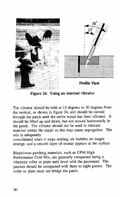
v i..:...
?_-_ii!i!i!i!_ !:
....................... ....:iii!iiii_iiiii_i.!i :_iiill_::i:_::::::
_,!::iiiiiiiii.:_!,!%11_:i:/:"i?i•.. :::.::+:.. _: • ..!:_........
:::_::::i............ ProfileView.............../.:i
:::::::::::::::::::::::::::::::::::::.............?:/::ii:i:::::::i..:
Figure 24. Using an internal vibrator
The vibrator should be held at 15 degrees to 30 degrees fromthe vertical, as shown in figure 24, and should be movedthrough the patch until the entire repair has been vibrated. Itshould be lifted up and down, but not moved horizontally inthe patch. The vibrator should not be used to relocatematerial within the repair as this may cause segregation. Themix is adequatelyconsolidated when it stops settling, air bubbles no longeremerge, and a smooth layer of mortar appears at the surface.
Bituminous patching materials, such as UPM HighPerformance Cold Mix, are generally compacted using avibratory roller or plate until level with the pavement. Thepatches should be compacted with three to eight passes. Theroller or plate must not bridge the patch.
8O

4.14 Screeding and Finishing
The surface of the patch should be troweled flush with thepavement surface. Vibration may be needed to make thework finishable if the mix is too stiff. Partial-depth repairsare usually small enough that a stiff board resting on theadjacent pavement can be used as a screed. The materialshould be worked toward the edges of the patch to establishcontact and enhance bonding to the pavement, as shown infigure 25. At least two passes should be made to ensure asmooth surface.
The repair surface must be hand-troweled to remove anyremaining minor irregularities, as shown in figure 26. Theedge of a repair located next to a transverse joint should betooled to provide a good reservoir for joint sealing. Extramortar from troweling can be used to fill any saw overcuts atthe patch corners. Extra epoxy may also be used, or the sawovercuts may be filled with joint sealant during the jointsealing process.
Partial-depth repairs typically cover only a small portion ofthe pavement surface and have little effect on skid resistance.
However, the finished surface of the repair should match thatof the pavement as closely as possible.
4.15 Curing
Curing is as important for partial-depth repairs as it is forfull-depth repairs. Since partial-depth repairs often havelarge surface areas in relation to their volumes, moisture canbe lost quickly. Improper curing can result in shrinkagecracks that may cause the repair to fail prematurely.
81
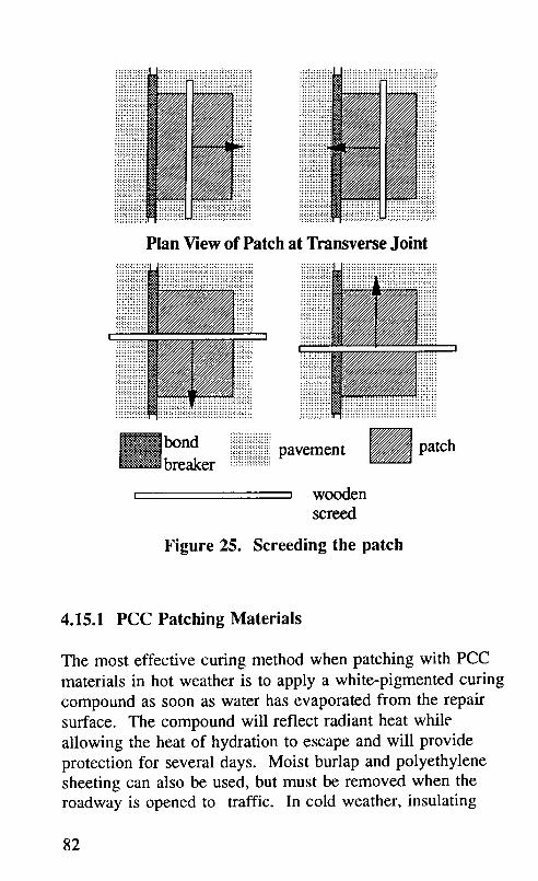
iiiiiiiiii!:i:ii i:i:i:iiiil
Plan View of Patch at Transverse Joint
I
:::::::::::::::::::::_ _" :?:i::i::i:: ,
bond iiiiii::iiiii:ilili.i.!.ipavement patch_ breaker __"_:_:_:_:_:_:_:_:_:_
t _ woodenscreed
Figure 25. Screeding the patch
4.15.1 PCC Patching Materials
The most effective curing method when patching with PCCmaterials in hot weather is to apply a white-pigmented curingcompound as soon as water has evaporated from the repairsurface. The compound will reflect radiant heat whileallowing the heat of hydration to escape and will provideprotection for several days. Moist burlap and polyethylenesheeting can also be used, but must be removed when theroadway is opened to traffic. In cold weather, insulating
82

_._._.i!.:::_::_.ii_iiiiiiiiiiiiiiiim_!!_!...............::::
_=_i_!_:i::;_!_iiii!iiiiiiii%!_iii!iiiii_iiii!il•::::i!iiiiiiiiiiii_iiiiiiiii_i:'.:i:_::i_i_iiiiiiiiiiiiiiiiiiiii!iii_:i_::
.: ...._?_._!_._._._._._._._._._:L._..._._._!!_!_!_.!_!_._._._._._._._._._i_._._._
.:!:iiiiiiiiiiiiiiiiiiiiii_iii!:!:.:._:::...............:.......................
.... ii! !ii̧ :: _ .:..:....:.:._._:.:.=;.:_::_;:.:::;...
Figure 26. Finishing the patch
blankets or tarps can be used to provide more rapid curingand to allow an earlier opening to traffic. The requiredcuring time should be stated in the project plans andspecifications.
4.15.2 Proprietary Patching Materials
Some proprietary materials may require some form of moistcuring after the mix has stiffened (e.g., Five Star HP).Others require the application of a curing compound (e.g.,Pyrament 505). Some proprietary repair materials may beair-cured (e.g., SikaPronto 11). Epoxy and proprietary repairmaterials should be cured as recommended by theirmanufacturers.
83

4.16 Joint Sealing
The final step in partial-depth spall repair is restoring thejoints. When the recommended scored bond breaker hasbeen used, the tear-off top strip should be removed, as shownin figure 27, and the selected sealant applied (see section3.4.4). If a scored bond breaker has not been used, jointrestoration is accomplished by resawing the joint to a newshape factor, sandblasting and airblasting both faces of thejoint, inserting a closed-cell backer rod, and applying thesealer. A minimum 1-week cure time should be allowed
before joint sealing. Consult the Materials and Proceduresfor Repair of Joint Seals in Concrete Pavements-Manual ofPractice for more information on proper joint sealingpractices. 15
4.17 Cleanup Requirements
The material manufacturer's instructions should be consulted
for infonrmtion on cleaning equipment that has been used tomix, place, and finish their material. The cleaning solventfor most cementitious materials is simply potable water.Some proprietary materials may require a special solvent;table 5 shows which of several rapid-setting repair materialsrequire a special cleaning solvent. Equipment must becleaned i_ru-nediately after use so it will not contaminate thenext material it contacts.
4.18 Opening to Traffic
Compressive strength requirements for paving concrete aregenerally specified at 3,000 psi (20,700 kPa) at 28 days. Therepair concrete should develop an equal or greater strength bythe time it receives traffic loadings. However, to minimize
84

...:!!'!!.::.,,
.::_:i._ii: removing
i:iii.!iiiii thete_-otr
":_:_.ii.ii.:!iiiiii! !i_i!iiiii joint""_:_:__333_._3:.... sealant
•"<.U.!._y
applied joint _ bondF sealant breaker
i!ii!i!i iiii!iiiiiiii!iiiill=.• :}illi::i!i!ii:i!!i!ii!iiiiiiiiiiii!i:i iiiiii:ilipavement
Profile View
Figure 27. Removing the tear-off top strip ot' a jointbond breaker
lane closures, traffic loadings may be allowed on a patchedarea when the repair concrete has attained the minimumstrength needed to assure its structural integrity. Thecompressive strength required for the opening of partial-depthpatches to traffic may be lowered because of their lateralconfinement and shallow depth.
The specifications of rapid-setting proprietary mixes shouldbe checked for recommended opening times. Cylinders orbeams can be tested for strength to determine what opening
85

time will allow the repair material to develop enoughstrength. The time to opening to traffic at 70°F (21°C) forseveral rapid-setting partial-depth spall repair materials isshown in table 1.
4.19 Inspection
Quality control and inspection of the entire constructionprocess is crucial to the success of the repair. Fieldexperience has shown that each step in the partial-depth spallrepair process requires careful supervision and inspection.An inspector must continually observe the various operationsto ensure that proper procedures are being followed.Appendix D contains detailed checklists for each step of theinspection process.
86

5.0 Evaluating Partial-Depth PatchPerformance
It is good practice to monitor the performance of partial-depth patches. By doing so, patch performance factors canbe determined and used in comparing cost-effectiveness ofdifferent material-procedure patch treatments. One methodfor calculating a performance factor is described in thischapter.
5.1 Data Required
To determine the effectiveness of a given patch type(material-procedure combination), a field survey must beconducted periodically. The highway agency must count thenumber of patches from the initial patching operation thathave failed, as well as the number of patches lost torehabilitation (e.g., overlay or slab replacement) since thetime of installation. The time of the field survey must alsobe recorded. Table 8 shows a typical collection of patchperformance data.
Figure 28 shows several plots of patch survival over time. Inall three cases, the percent of patches remaining after 10years is 80 percent. However, patch type B would have thehighest patch survival rate when compared with patch typesA and C, because it performed better longer than the othertwo patch types (and therefore has a larger area under itssurvival curve).
87

Table 8. Sample patch performance data
Time of Patches Cumm. Cumm. Percent
survey in-place patches patches lost patches(years) failed to rehab, surviving
(Tt) (Rip) (Rf)_ (RI)2 (p_)3
0 200 0 0 100
1 194 6 0 97
2 186 12 2 94
3 180 16 4 92
4 175 20 5 90
6 153 38 9 80
1 Re = the numberof patchesthat havefailedsince the time ofinstallation.
2 R1= the numberof patchesthat havebeen lost to rehabiliultion,suchasoverlayor slabreplacement,since the time of inst_dlation.
3 p, = {R_p/ (R,+ R_p)}x I00
5.2 Calculations
The patch survival rate is the area under the patch survivalcurve. The worksheet presented in table 9 can be used tocalculate the area for any available patch survival data. Itallows the systematic calculation of the area under the patch
88

89

Table 9. Worksheet for calculating patch survival rate
No. of Time Percent Avg. % No. of Time Partial TotalObserv. (years) Survived Survived Time Interval Area Possible
(t) (T3 (Ps) Interval (years) Area(P.vg(o)' (t) (I02 (Ar_t)) 3 (A_,,_o)4
1 0 100
• :..... .:..:.:_.._... • ..._.::: 98.5 1 1 98.5 100
.::::.. i 2 ":.::::.:.i.:?i..... .. : 97"i:; .:!::i1::i..".::::" " :: .::i . " "r. .. .::i?:::;i.".....: " . ... :.:..........." "95.5. " 2.....:, :"":1_:::....... 95.5_...:: ::100
..:-_:.:::::.:::!;:_i_ 2..:.._::_:_.:...:.:¢_:.:?:.:::. ........... ".............. ".....................::'.: " I ...... •93 3 1 93 100
4 3 9291 4 1 91 100
5 4 9085 5 2 170 200
6 6 806
77
88
99
1010
1111
1212
1313
1414
1515
1616
17 I
Sum Total 548 I 600
1 Pav_o = (P.) + Ps(m)) / 2 2 I.) = T(t+o - T(03 Ap_( ° = P_o x I._ 4 A_o,(,) = i(° x 100
Patch Survival Rate = (]_Apa.rm)/Y_Atot.)) x 100= (548 / 600) x 100= 91.3%
90

survival curve between each time of observation, as well asthe final calculation of a performance rating by which patchtypes can be compared. As an example, the data from table8 have been used to calculate a patch survival rate, using theworksheet in table 9.
The average percent of patches surviving, Pavg,is calculatedby averaging the two percent values that straddle the linebeing calculated, as shown in the shaded region of theworksheet in table 9. Each time interval, It, is calculated bysubtracting the earlier time, Tt, from the later time, T,.,, againfor the two lines straddling the line being calculated.
Each partial area under the percent patch survival curve, Ap.,,,is calculated by multiplying the P.,vgand I t values for thatline. Each total area, Ato t, is calculated by multiplying thetime interval, It, by 100. The total area under the patchsurvival curve, Atot, represents the best possible performancethat could occur for a patch type, i.e, 100 percent of allpatches survived during the observed time period.
The patch survival rate is calculated by dividing the sum ofthe partial areas, Ap_t, by the sum of the total possible areasunder the curve, Atot, and then multiplying by 100.
91

Appendix A
Material Testing Specifications
The following specifications for partial-depth spall repairmaterials are given as a guideline only and should bemodified to reflect the conditions and requirements of aparticular climatic region or roadway classification.
A.1 Rapid-Setting Cementitious Concretes
The cementitious rapid-setting patching materials and somenon-flexible rapid-setting polymer materials (e.g., SikaPronto11) shall meet the following suggested guidelines foracceptance as approved materials.
Initial set time, minimum ................... 15 minCompressive strength
ASTM C 39, 3 hours ................. 1000 psiCompressive strength
ASTM C 39, 24 hours ................ 3000 psiBond strength of epoxy-resin systems
ASTM C 882 ....................... 200 psiBond strength of concrete overlay and
patching materials, California test ......... 200 psiFlexural strength
ASTM C 78 ........................ 450 psiFreeze-thaw resistance
ASTM C 666, Procedure A (150 cycles) .... 15 gramsScaling resistance
ASTM C 672 (I00 cycles) .................. 5Surface abrasion resistance
California Test T550 ................. 25 gramsThermal compatibility
ASTM C 884 ......................... pass
93

A.2 Rapid-Setting Flexible Polymer Concretes
The flexible polymer materials shall meet the followingsuggested guidelines for acceptance as approved materials.
Initial set time, minimum ................... 15 minBond strength of epoxy-resin systems
ASTM C 882 ....................... 200 psiBond strength of concrete overlay and
patching materials, California test ......... 200 psiFreeze-thaw resistance
ASTM C 666, Procedure A (150 cycles) ....... 15 gScaling resistance
ASTM C 672 (100 cycles) .................. 5Surface abrasion resistance
California Test T550 .................... 25 gThermal compatibility
ASTM C 884 ......................... pass
A.33 Bituminous Materials
Bituminous patching materials shall meet the agency'ssuggested guidelines for acceptance as approved materials.Tests for workability, stripping, drainage, and cohesion arehighly recommended. Additional tests suggested by otheragencies and proprietary material manufacturers may also beused. Consult Appendix A of Materials and Procedures forthe Repair of Potholes in Asphalt Pavements-Manual ofPractice for more information on compatibility andacceptance tests for bituminous cold mix materials. _7
94

Appendix B
Sample Cost-Effectiveness Calculations
This appendix contains sample worksheets for cost-effectiveness calculations. Different material and procedurecombinations illustrate the financial differences betweenpatching operations.
When using the examples in the following sections, it isimportant to remember that crew size and productivity differgreatly among agencies. These examples are fictitious andtheir only purpose is to show how the worksheets are usedwhen completing them with the information relevant to aparticular agency.
Table B-1 is a blank worksheet that may be used tosummarize the patch performance data on a particular patchtype. Table B-2 is a blank worksheet that may be used tocalculate the patch survival rate, which is used in the cost-effectiveness worksheet. Chapter 5 explains the use of bothof these worksheets.
Each example considers the placement of 200 partial-depthpatches with an average finished patch length of 18 in(457.2 mm), width of 9 in (228.6 ram), and depth of 2 in(50.8 mm). Therefore, for all examples the expected totalvolume of the finished patches is 1.39 yd3 (1.06 m3). Theaverage daily wage for the maintenance worker is assumed tobe $120 in each example. Other data vary from example toexample.
Calculation of the amount of materials needed, such as apatching material, bonding agent, joint bond breaker, orcuring compound, is not demonstrated. The examplesassume that agencies are already familiar with thesecalculations based on the number, length, width, and depth ofthe patches, and a typical waste factor for each material.
95

Table B-1. Blank patch performance data worksheet
Time of Patches Cumm. Cumm. Percent
survey in-place patches patches lost patches(years) failed to rehab, surviving
(Tt) (Rip) (Rf) 1 (Ri) 2 (Ps) 3
04 0 0 100
1 Rf = the number of patches that have failed since the time ofinstallation.
2 RI = the number of patches that have been lost torehabilitation, such as overlay or slab replacement, since thetime of installation.
3 Ps = {Rip / (Rf + Rip)} x 1004 Installation.
96

Table B-2. Blank worksheet for calculating patchsurvival rate
No. of Time Percent Avg. % No. of Time Partial TotalObserv. (years) Survived Survived Time Interval Area Possible
(0 (T,) (P,) Interval (years) Area(P.,,_)_ (t) (I0" (A_o)_ (A,,_o)'
1 0 100
12
23
34
45
56
67
78
89
910
1011
1112
1213
1314
1415
1516
1617
Sum Total [ I
1 P,.v_¢O= (P_¢t)+ P,¢t+l))/ 2 2 i(t) = T<,+I)_ T¢°3 Ap,rt(,)= P,vs(,)x I(t ) 4 Atot(o = I(t) X 100
Patch Survival Rate = (EApm(t)/5"A_,t(t))x 100
97

B.1 Example 1
Example 1 considers the placement of 200 material "A"patches using the saw-and-patch procedure. Material, labor,and equipment costs can be directly entered on the cost-effectiveness worksheet. However, the average dailyproductivity, the estimated number of days for the patchingoperation, and the partial-depth patch survival rate require afew advance calculations.
In calculating the average daily productivity and estimatednumber of days for patching, the examples assume that thelast patch will be placed at the latest possible time and thatpreparation will stop when there is enough time to place thelast patch. Therefore the patch preparation rate will controlthe number of patches that can be placed per day. Theexample also assumes that a crew of seven places sevenpatches per hour, and that the average patch volume is0.187 ft_(0.005 m3).
Patches prepared per hour = 7Work hours per day = 8Material cure time = 4 hrNumber of hours available for preparation
and placement = work hrs - cure hrs = 4 hrAverage preparation rate =
(7 patches/hr) x (0.187 ft3/patch) = 1.31 ft3/hrAverage daily productivity =
4 hr x 1.3 ft3/hr x (1 patch/0.187 ft3) = 28 patchesEstimated number of days for patching
(rounded up) = 200 / 28 = 8 days
The patch survival rate is calculated using tables B-3 andB-4. Assume that in a previous project, 200 partial-depthpatches made with material "A" had been placed using thesaw-and-patch procedure. If these 200 patches experienced a30 percent failure rate over the 10 years following theirinstallation, the patch survival rate would be 85 percent, asshown in table B-4. Figure B-1 shows the completed cost-effectiveness worksheet for this example.
98

Table B-3. Example I patch performance data
Time of Patches Cumin. Cumm. Percentsurvey in-place patches patches lost patches(years) failed to rehab, surviving
(TI) (Rip) (Rf)l (Rl)2 (Ps) 3
0 2O0 0 0 100
10 140 60 0 70
Rf = the number of patches that have failed since thetime of installation.2 R_= the number of patches that have been lost torehabilitation, such as overlay or slab replacement, since thetime of installation.
3 Ps = {Rip/(Rf + Rip)} × 100
Table B-4. Example 1 patch survival rate calculation
No. of Time Percent Avg. % No. of Time Partial TotalObserv. (years) Survived Survived Time Interval Area Possible
(t) (Tt) (P,) Interval (years) Area(P.v_,))' (t) (I,)2 (A_,)) 3 (At_o)'
1 0 100
85 11101850110002 10 70
Sum Total I 85oI lOOOI = (Ps(t)+ Ps(t+l))/ 2 23 Pavg(t) 4 I(t) = T(t+D - T(t)
Apart(t) = Pavg(t) × I(t) Atot(t) = I(t ) X 100
Patch Survival Rate = (_Apart(t)/_Atot(t))x 100(850 / 1000) x 1000 = 85%
99

ESTIMATE OF PROJECT SIZE OR SEASONAL PARTIAL-DEPTH PATCHING NEEDS
amount units
Expected Number of Patches 200 (A)Average Finished Patch Length 18 in _B_)Average Finished Patch Width 9 in (B2)Average Finished Patch Depth 2 in (B3)Expected Total Volume of Finished Patches
(B_ x B2 x B3x A) + 46656 1.39 yd 3 (C)
MATERIAL COSTS (e.g., cold mix, cement, aggregate, sand, bondingagent, joint bond breaker, curing agent, etc.)
Material 1 = Patching Material "A"
Material 1 Purchase Cost 132 $/yd 3 (D_)Expected Material 1 Needs 1.60 yd 3 (El)Material 1 Shipping Cost 0 $ (Fl)Total Material 1 Cost [(D_ x El) + Ft] 211 $ (G_)
Material 2 = Bonding Agent
Material 2 Purchase Cost 45 $/gal (D2)
Expected Material 2 Needs 15 gal (E:)Material 2 Shipping Cost 0 $ (F2)
Total Material 2 Cost [(D2 x E2) + Fz] 675 $ (G2)
Material 3 = Joint Bond Breaker
Material 3 Purchase Cost 0.328 $/ft (D_)Expected Material 3 Needs 500 ft (Es)Material 3 Shipping Cost 0 $ (1::3)Total Material 3 Cost [(D3 x E3) + F3] 164 $ (G3)
Material 4 = Curing CompoundMaterial 4 Purchase Cost 10 $/gal (D4)Expected Material 4 Needs 2 gal (E4)Material 4 Shipping Cost 0 $ (F4)Total Material 4 Cost [(D4 x E4) + F.] 20 $ (G4)
Figure B-1. Example 1 cost-effectiveness worksheet
100

LABOR COSTSamount units
Number in RepairCrew 9 (H)Average Daily Wage per Person 120 S/day (I)
Number in Traffic Control Crew 2 (J)Average Daily Wage per Person 120 S/day (K)
Supervisor Daily Wage 200 S/day (L)
EQUIPMENT COSTS
Material Truck 20 S/day (M)
Traffic Control Trucks ,andSigns 150 S/day (N)
Patch Prep,'uationEquipment(e.g., concrete saw, jackh,'unmer, 225 S/day (O1)milling machine, waterblaster) 60 S/day (02)
Cleaning Equipment 350 S/day (P1)(e.g., sandblaster, airblaster) 0 S/day (P2)
Mixing Equipment 35 S/day (Q1)(e.g., mo_tr mixer, Jiffy mixer) 0 S/day (Q2)
Consolidation/CompactionEquipment(e.g., pencil vibrator, vibratingscreed, vibratory roller) 20 S/day (R)
Extra EquipmentTruck 0 S/day (S)
Miscellaneous Equipment 0 S/day (T1)(e.g., spray-injectionmachine, 0 S/day (T2)joint sealing equipment,etc.)
Figure B-I. Example 1 cost-effectiveness worksheet
(continued)
101

SUMMARY COSTSamount units
Toted Material Cost
(Gi + G2 + G3 + G4 + ...) 1070 $ (U)
Total Daily Labor Cost[(H x I) + (J x K) + L] 1520 S/day (V)
Toted Equipment Cost[M + N + (O1 + 02 + ...) +(P1 + P2 + ---)+ (Q1 + Q2 + ...) +R + S + (T 1 + T2 + ...)] 860 S/day (W)
User Costs 1000 S/day (X)
Average D_fily Productivity 28 patches/day (Y)
Estimated Number of Daysfor Patching Operation(A + Y) 8 days (Z)
Total Labor and Equipment Cost[(V + W) x Z] 19,040 $ (AA)
Total Patching Operation Cost[U + AA + (X x Z)] 28,110 $ (BB)
Parti,'d-depth Patch Survival Rate 1(Duration may vary) 85 % (CC)
Effective Patching Cost[BB x (2 - {CC + 100})] 32,327 $ (DD)
Until patch survival rates have been determined, agency experienceshould be applied. See chapter 5 for calculation examples.
Figure B-I. Example 1 cost-effectiveness worksheet
(continued)
102

B.2 Example 2
Exarnple 2 considers the placement of 200 material "B"patches using the chip-and-patch procedure. As in example1, material, labor, and equipment costs can be directlyentered on the cost-effectiveness worksheet. However, theaverage daily productivity, the estimated number of days forthe patching operation, and the partial-depth patch survivalrate require a few advance calculations as well.
The same assumptions made in example 1, regarding thecalculation of the average daily productivity and estimatednumber of days for patching, are made here. This exampleassumes that sawing equipment will be needed to reestablishthe joints, and that the chip-and-patch preparation processwill have the same productivity as the saw-and-patchpreparation process, because the time needed forjackhammering will take up the time not needed for sawing.
The patch survival rate is calculated using tables B-5 andB-6. This example assumes that the agency is familiar witha previous project in which 200 partial-depth patches madewith material "B" were placed using the chip-and-patchprocedure. In this fictitious project, 25 patches failed duringthe five years following installation, and 55 more patchesfailed during the next five years. Table B-6 shows that thispattern of failure results in a patch survival rate of 84percent. Figure B-2 shows the completed cost-effectivenessworksheet for this example.
103

Table B-5. Example 2 patch performance data
Time of Patches Cumm. Cumm. Percentsurvey in-place patches patches lost patches(years) failed to rehab, surviving
(Tt) (R_r) (Rf)I (R,)2 (ps)3
0 200 0 0 100
5 175 25 0 87.5
10 120 80 0 60
Rf = the number of patches that have failed since the timeof installation.
2 R_= the number of patches that have been lost torehabilitation, such as overlay or slab replacement, sincethe time of installation.
3 Ps = {Rip / (Rf + Rip ) } × 100
Table B-6. Example 2 patch survival rate calculation
No. of Time Percent Avg. % No. of Time Partial TotalObserv. (years) Survived Survived Time Interval Area Possible
(t) (Tt) (P_) Interval (years) Area(P._s_o)l (t) (0 2 (Argo) 3 (A_o)'
I 0 100
94 1 5 470 5002 5 87.5
74 2 5 370 5003 10 60
SumTotal I 840 I 1000
t Pavg(t) = (Pso)+ Ps(t+o) / 2 2 l(t) = T(t+l) _ T(t)
3 Apart(t) = Pavg(t) x I(t ) 4 Atot(t ) _= i( 0 × 100
Patch Survival Rate = (_Apart¢t)/_Atot¢t))× 100= (840 / 1000) x 100 = 84%
104

ESTIMATE OF PROJECT SIZE OR SEASONAL PARTIAL-DEPTH PATCHING NEEDS
amount units
Expected Number of Patches 200 (A)Average Finished Patch Length 18 in (Bl)Average Finished Patch Width 9 in (B2)
Average Finished Patch Depth 2 in (B3)Expected Total Volume of Finished Patches[(B l x B2 × B3 × A) + 466561 1.39 yd3 (C)
MATERIAL COSTS (e.g., cold mix, cement, aggregate, sand, bonding
agent, joint bond breaker, curing agent, etc.)
Material l = Material B
Material 1 Purchase Cost 214 $/yd 3 (Dr)Expected Material 1 Needs 1.60 yd_ (El)Material 1 Shipping Cost 0 $ (F 0Total Material 1 Cost [(D_ x E_) + Ft] 342 $ (G_)
Material 2 = Joint Bond Breaker
Material 2 Purchase Cost 0.348 $/f (D_)Expected Material 2 Needs 500 ft (E2)Material 2 Shipping Cost 0 $ (F2)Total Material 2 Cost [(D 2x E2) + F2] 174 $ (G2)
Material 3 =
Material 3 Purchase Cost 0 $/ (D3)Expected Material 3 Needs 0 (E3)
Material 3 Shipping Cost 0 $ (F3)Total Material 3 Cost [(D3 x E3) + F3I 0 $ (G3)
Material 4 =
Material 4 Purchase Cost 0 $/ (D4)Expected Material 4 Needs 0 (E4)Material 4 Shipping Cost 0 $ (F4)Total Material 4 Cost [(D4 x E4) + F,] 0 $ (G,)
Figure B-2. Example 2 cost-effectiveness worksheet
105

LABOR COSTS
amount units
Number in Repair Crew 7 (H)
Average Daily Wage per Person 120 S/day (I)
Number in Traffic Control Crew 2 (J)
Average Daily Wage per Person 120 S/day (K)
Supervisor Daily Wage 200 S/day (L)
EQUIPMENT COSTS
Material Truck 20 S/day (M)
Traffic Control Trucks ,and Signs 150 S/day (N)
Patch Preparation Equipment(e.g., concrete saw, jackhammer, 225 S/day (O j)milling machine, waterblaster) 60 S/day (02)
Cleaning Equipment 350 S/day (Pl)(e.g., sandblaster, airblaster) 0 S/day (P2)
Mixing Equipment 35 S/day (QI)(e.g., mortar mixer, Jiffy mixer) 0 S/day (Q2)
Consolidation/Compaction Equipment(e.g., pencil vibrator, vibratingscreed, vibratory roller) 20 S/day (R)
Extra Equipment Truck 0 S/day (S)
Miscellaneous Equipment 0 S/day (TI)(e.g., spray-injection machine, 0 S/day (T2)joint sealing equipment, etc.)
Figure B-2. Example 2 cost-effectiveness worksheet(continued)
106

SUMMARY COSTSamount units
Total Material Cost
(G1 + G2 + G3 + G4 + ...) 516 $ (U)
Total Daily Labor Cost
[(H x I) + (J x K) + L] 1280 S/day (V)
Total Equipment Cost[M + N + (O1 + 02 + ...) +(P1 + P2 + ...) + (01 + 02 + ...) +
R + S + (T1 + T2 + ...)] 860 S/day (W)
User Costs 1000 S/day (X)
Average Daily Productivity 28 patches/day (Y)
Estimated Number of Daysfor Patching Operation
(A + Y) 8 days (Z)
Total Labor ,and Equipment Cost[(V + W) x Z] 17,120 $ (AA)
Toud Patching Operation Cost
[U + AA + (X x Z)] 25,636 $ (BB)
Partial-depth Patch Survived Rate )
(Duration may vary) 84 % (CC)
Effective Patching Cost[BB x (2 - {CC + 100})] 29,738 $ (DD)
Until patch survival rates have been determined, agency experienceshould be applied. See chapter 5 for calculation examples.
Figure B-2. Example 2 cost-effectiveness worksheet(continued)
107

Appendix C
Material and Equipment SafetyPrecautions
This appendix contains some common-sense safetyprecautions for using materials and equipment in the partial-depth spall repair process. These precautions are not acomplete list, nor will they apply to all materials andequipment. It is essential that the highway agency obtain,review, and follow safety data sheets for all materials andall equipment. The agency should develop a safety trainingprogram that will properly instruct highway workers in thesafe use of all materials and equipment involved in partial-depth spall repair.
C.I Materials
Some common-sense precautions for the safe use of manyrapid-setting materials, admixtures, bonding agents, curingcompounds, and solvents include the following:
• To avoid skin contact during mixing, placing, andcleaning
- Wear long-sleeved shirts.- Wear long pants°- Wear gloves.- Wear steel-toed boots.
• To avoid ingestion during mixing, placing, and cleaningWear eye protection.
- Wash hands (even if gloves have been worn)before handling anything that will go into themouth (e.g., lunch containers, silverware, food,drinks, tobacco, gum, etc.).
- Wash hands before touching the face, eyes, nose,mouth, or any other part of the body.
109

- Avoid inhaling fumes and vapors (use respiratorsif required).
- Use in well-ventilated areas.
• To avoid creating additional toxic vapors or fumesnever combine any substances unless following thespecific instructions of the manufacturers of thosesubstances. This includes combination by mixing, bycleaning, by adjacent placement, by contamination, etc.
C.2 Equipment
Some common-sense precautions for the safe use of typicalpartial-depth spall repair equipment include the following:
• Wear eye protection, gloves, long-sleeved shirts, longpants, and steel-toed boots during sawing,jackhammering, sandblasting, airblasting, milling,waterblasting, spray injection, and any other operationthat could injure the skin, eyes, limbs, etc.
• Use ear protection during sawing, jackhammering,sandblasting, airblasting, milling, waterblasting, sprayinjection, and any other operation that is loud and couldpermanently damage the hearing.
110

Appendix D
Inspection Checklists for Construction
This appendix is intended for inspectors of the partial-depthspaU repair process. It contains discussions of planning,equipment, and procedures crucial to successfully completinga partial-depth spall repair project. Checklists pertaining toeach step of the process-including planning, equipment,material mixing, patch preparation, material installation, andsafety precautions-are provided.
D.1 Plans and Specifications
Plans must be prepared and distributed to the inspector andthe supervisor of the installation crew. The plans mustcontain the following information:
[] 1. Project layout (including stationing, slab lengths,location of spalls to be repaired, etc.)
[] 2. Original pavement material type[] 3. Location and type of any pre-patching repairs
required[] 4. Required patch dimensions[] 5. Required joint reservoir dimensions
Specifications may be based either on adherence todesignated procedures or on achieving a quality end-product.They may also combine the two. Procedure-basedspecifications must contain the following information:
[] 1. Delivery and storage requirements[] 2. Equipment requirements[] 3. Material requirements[] 4. Material mixing procedure requirements[] 5. Patch preparation procedure requirements[] 6. Installation procedure requirements[] 7. Weather condition limitations
111

[] 8. Traffic control requirements[] 9. Material disposal requirements.[] 10. Safety requirements
End-result specifications must contain the followinginformation:
[] 1. Delivery and storage requirements[] 2. Required results of mixing procedures and
acceptance-rejection criteria[] 3 Required results of each preparation procedure and
acceptance-rejection criteria[] 4. Required results of the installation process and
acceptance-rejection criteria[] 5. Weather condition limitations[] 6. Traffic control requirements[] 7. Material disposal requirements[] 8. Safety requirements
Most projects combine procedure-based and end-resultspecifications. The following inspection process is based ontheir combination.
D.2 Equipment
All equipment must be inspected and approved before theproject begins, as well as during mixing, patch preparation,patch installation, and sealant installation. A list of proposedequipment should be submitted before installation forapproval. During the pre-installation inspection, the inspectorshould check all equipment, ensuring that each piece meetsthe project specifications. Suitability of equipment formixing and placing a particular repair material can beconfirmed by contacting the material manufacturer.
The condition and effectiveness of each piece of equipmentshould be checked at the beginning of each day of patchpreparation, mixing, and installation.
112

D.3 Material Quality
The inspector must confirm that the patching materials, jointbond breaker, bonding agent, curing compound, and so onare from the agency's "approved list" or are from a certifiedplant, and that samples of the materials have been submittedto the agency's laboratory for testing. The materialmanufacturer's recommendations for storage and shelf lifeshould also be checked. Materials that are not stored
properly or that are old may not meet quality standards.
D.4 Field Installation
After all required slab stabilization and other prepatchingrehabilitation have been completed and approved, the partial-depth spall repair process can begin. Inspector(s) andsupervisor(s) should meet before work begins to discuss thefollowing subjects:
[] 1. Exact locations and dimensions of all spalls to bepatched. (The boundaries should be clearlymarked.)
[] 2. Traffic control requirements and lane closure timelimitations
[] 3. Methods for preparing and cleaning repair areas,for mixing and placing the repair materials, and forreinstalling a joint sealant system
[] 4. Recommended accessory materials and instructionsfor their use
[] 5. Material properties and working tolerances[] Working times[] Time to traffic at the anticipated mixing and
placement temperatures[] Moisture conditions allowable during
placement[] Temperatures allowable during mixing and
placement[] 6o Mixing times, components, proportions, and
sequences
113
[] 7. Criteria for approval of all cleaning and installationequipment and processes
[] 8. Criteria for final approval of the repair work[] 9. Any localized variations from the specified
methods[] 10. Procedures in the event of hot, cold, and/or wet
weather[] l l. Material disposal requirements[] 12. Safety requirements for all equipment and
procedures and material safety data sheets
D.5 Preparing the Repair Area
Patch preparation includes removing deteriorated concreteand old sealant in the adjacent joint, final cleaning, installingthe joint bond breaker, and applying the bonding agent. Thefollowing inspection checklist can be used to ensure that spallpreparation is completed properly. Not all of these patchpreparation procedures are used at one time.
[] 1. Sounding:[] A solid steel rod, chain, or ballpeen hammer is
used to sound the spalled area before and afterthe deteriorated concrete is removed.
[] All deteriorated concrete is removed using thespecified method until all parts of the repairarea yield a clear ringing sound when they aresounded.
[] 2. Sawing:[] The concrete saw is establishing straight,
vertical patch boundaries to the required depth,where specified°
[] The concrete saw is removing the requiredamount of concrete and sealant in any adjacentjoint.
[] The concrete saw is uniformly cutting to theproper width and depth. (Depth and width canbe checked quickly using a metal template.)
114

[] 3. The water-wash equipment is removing all sawingand/or waterblasting slurry from the repair areabefore it dries.
[] 4. Jackhammering:[] Jackhammers of the specified weight are
removing all deteriorated concrete to thespecified depth, without fracturing the soundconcrete below the repair or undercutting orspalling any sawed boundaries.
[] Chiseling is begun in the center of the repairarea and proceeds outward.
[] Only light jackhammers are used near thepatch boundaries.
[] If patch boundaries have not been sawed, thehammering is producing rough, vertical edges(not scalloped edges into which the repairmaterial will have to be feathered).
[] Spade bits (not gouge bits) are being used.[] Jackhammers are being operated at an angle
less than 45 degrees from the vertical.[] 5. Milling:
[] The carbide-tipped milling machine isremoving all deteriorated concrete to thespecified minimum depth.
[] Any material that remains at the patch cornersis removed by light jackhammering or sawing.
[] Whenever possible, the milling machine isoriented such that the rounded edges of themilling hole are parallel to the direction oftraffic.
[] If this is not possible, the rounded edgesare chipped into straight, vertical edges.
[] Edge spalling is minimized.[] 6. Waterblasting:
[] A protective shield has been built around therepair area before waterblasting if traffic ispassing in the next lane.
[] The waterblasting equipment has beencalibrated to remove the specified depth ofconcrete
115

[] Operation parameters are not changedthroughout the remainder of the project unlessthe concrete changes (e.g., the aggregatehardness differs from one pavement section toanother).
[] The waterblasting equipment is removing alldeteriorated concrete to the required depth, andis producing neat, vertical faces at the patchboundaries.
[] Waterwashing equipment is used to wash thewaterblasting slurry from the repair area beforeit dries.
[] 7. A full-depth repair is used if at any point in thepatch preparation process, the deteriorated area ofconcrete is found to be deeper than the top third ofthe pavement slab, or if reinforcing bars or meshare encountered.
[] 8. Hand tools and shovels are being used to removeall loose material, when preparing the patch underadverse conditions.
[] 9. Sandblasting:[] The sandblasting equipment is uniformly
cleaning the faces of the repair area. Thistypically requires that the nozzle be held 1 into 2 in (25 mm to 51 mm) from the pavementand that several passes be made.
[] No old sealant, oil, or dried sawing and/orwaterblasting slurry remains in the repair area.
[] The sandblasting equipment does not introduceoil or moisture to the repair area.
[] After sandblasting, the entire surface area ofthe patch hole contains freshly exposedconcrete.
[] 10. Airblasting:[] The airblasting equipment is removing all dirt,
dust, old sealant, and sand from the dry repairarea.
[] The airblaster does not introduce oil ormoisture to the repair area.
[] After airblasting, the repair area is clean anddry.
116

[] 1I. Compressed air is removing all old sealant, sand,dirt, and dust from the pavement surface so that itcannot reenter the repair area, especially on windydays or when traffic passes next to the cleanedrepair areas.
[] 13. Recleaning:[] The repair area is re-checked for cleanliness
just before material placement.[] Cleaned repair areas that have been
recontaminated by rain, dew, dirt or oil, arecleaned again in a manner that restores theoriginal cleanliness. This may requiresandblasting and airblasting, or merelyairblasting.
[] Cleaned repair areas that are left ovemight are,at a minimum, airblasted again.
[] 14. The repair area is allowed to dry if a moisture-sensitive repair material will be used. (Water onthe surface of the repair area during materialinstallation may severely reduce the ability of thematerial to bond to the surface, depending on thematerial type. Watch for heavy dew that maycollect in the repair area and remain after thesurface is dry.)
[] 15. Scored bond breaker:
[] A strip of scored bond breaker is placed at thejoint-patch interface 1 in (25 mm) deeper thanthe repair, and extends at least 2 in to 3 in(51 mm to 76 mm) beyond the repairboundaries.
[] The bond breaker is either of the appropriateheight or is stacked and latex-caulked whennecessary so that there are no gaps throughwhich the repair material can flow.
[] A true, straight joint line is maintained wheninstalling the bond breaker.
[] 16. Bonding agent:[] The bonding agent sprayer or brush is
applying a thin layer of bonding agentuniformly over the repair area.
117
[] The bonding agent is still tacky when therepair material is placed.
[] 17. Safety:[] All required operator safety equipment is, in
use.[] All required safety precautions are followed.
D.6 Installing the Patch
Patch installation includes mixing, placing, and finishing thepatching material. The following inspection checklist canensure that patch installation is completed properly.
D.6.1 Mixing
During the mixing of the repair materials, the following itemsshould be regularly checked to ensure that they meet therequirements. Not all rapid-setting partial-depth spall repairmaterials require mixing.
[] 1. All mixing equipment is clean before use. Somematerial manufacturer's may recommend pre-wetting the mixer so no water is lost when mixingthe first batch.
[] 2. The water used for mixing is clean.[] 3. The mixing operation results in a consistently-
mixed material.[] 4. The material is not over- or undermixed.[] 5. Any spilled material is removed from the
pavement surface.[] 6. The mixing temperature is as recommended.
Warm water or ice water is used to raise or lowerthe mix temperature as needed.
[] 7. Mixing time, mix components, mix proportions,and mix sequences are carefully followed.
[] 8. The mixing equipment is cleaned with the solventspecified by the material manufacturerimmediately after use.
118

[] 9. The mixing of the bonding agent and repairmaterial is scheduled such that the bonding agentis tacky when the repair material is placed.
[] 10. Disposal of all wasted materials and solventsfollows the manufacturer's specifications and Stateordinances.
[] 11. All required operator safety equipment is in use.[] 12. All required safety precautions are followed.
Material that has begun to set during mixing, or materialthat is too wet, should not be placed. It should be discarded,and the mixing process begun again; a retarding agent mayneed to be added. The mixing time or amount of water mayalso need to be adjusted.
D.6.2 Placement
During placement, the following items should be regularlychecked to ensure that they meet the requirements. Not allsteps will be required for all materials.
[] 1. The repair material is placed in a clean repairhole, under the specified moisture conditions,using the specified placement methods.
[] 2. The bonding agent thoroughly coats the bottomand sides of the repair area, but does not collect inany pockets.
[] 3. The material is placed when the bonding agent isstill tacky.
[] 4. The repair hole is slightly overfilled with therepair material for those materials that requireconsolidation or compaction.
[] 5. A shovel is used (not a wheelbarrow or a bucket)to place repair materials that contain aggregate, sothat segregation does not occur.
[] 6. The repair material is not placed below or aboveits permissible placement temperature range.
[] 7. Deep repairs are placed in lifts to control heatdevelopment, when specified.
119

[] 8. A pencil vibrator or hand tools are used torelease trapped air from the mix.
[] 9. The vibrator is held at 15 to 30 degrees from thevertical, and is moved through the concrete bylifting it up and down to vibrate the entire areauntil the mix stops settling, air bubbles no longeremerge, and a smooth layer of mortar appears atthe surface.
[] 10. A bituminous cold mix patch is compacted torelease trapped air using a vibratory roller orplate until it is level with the pavement.
[] 11. Disposal of all wasted materials and solventsfollows the manufacturer's specifications and Stateordinances.
[] 12. Field testing is conducted as appropriate for thepatching materials, such as testing beams orcylinders for strength and quality control.
[] 13. All required operator safety equipment is in use.[] 14. All required safety precautions are followed.
D.6.3 Material Finishing and Curing
During finishing, the following items should be regularlychecked to ensure that they meet the requirements. Not allsteps will be required by all materials.
[] I. The repair material is troweled level with thepavement before finishing.
[] 2. The repair material is screeded with a stiff board,using at least two passes.
[] 3. The repair material is worked toward the patchedges to enhance bonding with the existing slab.
[] 4. The saw cuts are filled with excess mortar orepoxy, or are filled with joint sealant during thejoint resealing process.
[] 5. The patch surface is finished to match the surfaceof the surrounding pavement.
[] 6. Appropriate curing methods are used so thatshrinkage cracks do not develop.
120

[] Curing agents are applied uniformly to thepatch.
[] The water used for curing is clean.[] Insulating covers and longer cure times are
used at cooler temperatures, as specified by thematerial manufacturer.
[] 7. Disposal of wasted repair material, curingi:ompound, and cleaning solvents follows themanufacturer's specifications and State ordinances.
[] 8. Traffic is not allowed on the pavement until thematerial has developed the strength necessary tocarry traffic without being damaged.
[] 9. All required operator safety equipment is in use.[] 10. All required safety precautions are followed.
D.6.4 Joint Resealing
Consult the Materials and Procedures for Repair of JointSeals hi Concrete Pavements-Manual of Practice forinformation regarding the inspection of the joint resealingprocess. _5 In addition to the inspection criteria listed in thatmanual, when using a scored bond breaker, the followingcriteria should be met:
[] 1. Joint resealing or filling is conducted after aminimum curing time of one week.
[] 2. Immediately before joint resealing or filling, thetop strip is torn off of the scored bond breaker,leaving a uniform, clean, dry reservoir.
[] 3. Before resealing or filling the joints, low-pressureair cleaning is used if dust or dirt has blown intothe joints after removal of the tear-away top strip.
D.7 Final Inspection
During installation and before approval, the partial-depthpatches should be individually inspected, ensuring that thepatch meets the highway agency's criteria, and noting the
121

presence and severity of any distresses. The final inspectionshould include the following:
[] 1. The patch is bonded firmly to the existingpavement and has not separated from the sidewalls.
[] 2. The patch is level with the surface of the existingpavement.
[] 3. The patch contains no cracks (other than finehairline shrinkage cracks) or bubbles.
[] 4. All material that has spilled on the pavement hasbeen removed.
[] 5. No debris has been left on the pavement.
Consult the Materials and Procedures for Repair of JointSeals in Concrete Pavements-Manual of Practice forinformation regarding final inspection of the joint sealantsystem.15
122

Appendix E
Partial List of Material andEquipment Sources
This appendix contains a partial listing of material andequipment manufacturers. Addresses and phone numbers areprovided for manufacturers and/or suppliers who can providethe inquirer with information regarding products, installationpractices, safety procedures, costs, and local suppliers.
Material safety data sheets, where applicable, should beavailable from all manufacturers. Information regarding thesafe use of all materials and equipment should be carefullyfollowed to ensure worker safety and the safety of thetraveling public.
Inclusion of a particular material, piece of equipment, orsupplier in this list does not serve as an endorsement of thatmaterial, equipment, or supplier. Likewise, omission fromthis list is not intended to carry negative connotations for thematerials, pieces of equipment, and suppliers omitted.
E.1 Partial-Depth Patching Materials
E.I.I Manufacturers of Cementitious Concretes
Euclid Chemical Company19218 Redwood RoadCleveland, OH 44110-2799(216) 531-9222
Five Star Highway Products, Inc.425 Stillson RoadFairfield, CT 06430(203) 336-7900
123

Fosroc, Inc.55 Skyline DrivePlanview, NY 11802(516) 935-9100
Hartline Products Company, Inc.2186 Noble RoadCleveland, OH 44112(216) 451-6573
L&M Construction Chemicals, Inc.14851 Calhoun RoadOmaha, NE 68152(402) 453-6600
Master Builders
23700 Chagrin BoulevardCleveland, OH 44122(800) 227-3350
United States Gypsum CompanyIndustrial Gypsum Division125 South Franklin AvenueChicago, IL 60606-4678(312) 606-4000
E.I.2 Manufacturers of Polymer Concretes
Accelerated Systems Technology Corporation140 Chaparral CourtSuite 100Anaheim, CA 92808(714) 263-9074
HC Epoxy Company, Inc.862 East 19th StreetTucson, AZ 85719(602) 624-7929
124

Percol Polymefics, Inc.17435 Newhope StreetFountain Valley, CA 92708-4220(714) 979-5555
Pyrament/Lone Star Industries, Inc.340 North Sam Houston Parkway, EastHouston, TX 77060(800) 633-6121
Sika Corporation201 Polito AvenueLyndhurst, NJ 07071(201) 933-8800
The Burke CompanyP.O. Box 5818San Mateo, CA 94402(415) 349-7600(800) 423-9140
Thoro System ProductsDepartment PWM7800 N.W. 38th StreetMiami, FL 33166
E.I.3 Manufacturers of Bituminous Materials
Unique Paving Materials Corportation3993 East 93rd Street
Cleveland, OH 44105-4096(800) 441-4881
125

E.I.4 Manufacturers of Bonding Agents
Master Builders23700 Chagrin BoulevardCleveland, OH 44122and3637 Weston RoadToronto, ONT M9L lWlCANADA(800) 227-3350
The Burke Company6433 East 30th StreetIndianapolis, IN 46219(317) 543-4475
E.2 Partial-Depth Patching Equipment
E.2.1 Manufacturers of Sawing Equipment
Cimline, Inc.3025 Harbor LaneSuite 130Plymouth, MN 55447(800) 328-3874
Target Products Division4320 Clary BoulevardKansas City, MO 64130(816) 923-5040
Vermeer Manufacturing CompanyRoute 2P.O. Box 200Pella, IA 50219(515) 628-3141
126

E.2.2 Manufacturers of Spray-Injection Equipment
Zimmerman Equipment Corporation1000 South Thompson LaneNashville, TN 37211(615) 833-5705
Wildcat Manufacturing Company, Inc.Highway 81P.O. Box 1100Freeman, SD 57029(605) 925-4512
ONE MAN, Inc.7301 Jefferson, N.E.Suite A-113Albuquerque, NM 87109(505) 898-1900
E.2.3 Manufacturers of Waterblasting Equipment
FLOW Services23500 64th StreetKent, WA 98032(800) 446-3569, Ext. 900
E.2.4 Manufacturers of Milling Equipment
Cedarapids, Inc.916 16th Street, N.E.Cedar Rapids, IA 52402(319) 363-3511
Vermeer Manufacturing CompanyRoute 2P.O. Box 200Pella, IA 50219(515) 628-3141
127

E.2.5 Manufacturers of Jackhammers
Atlas Copco Berema, Inc.161 Lower Westfield RoadHolyoke, MA 01040(800) 284-2373(413) 536-0600
E.2.6 Manufacturers of Compacting Equipment
Stone Construction Equipment, Inc.Corporate Offices/Northern Manufacturing Plant32 East Main StreetP.O. Box 150Honeoye, NY 14471-0150(800) 888-9926
128

Glossary
Admixture-A substance added to a mixture during mixing.
Adverse patching conditions-Climatic conditions in whichthe air temperature is below 40°F (4°C) and the repairarea is saturated with surface moisture.
Bonding agent-A substance that promotes good bondingbetween the pavement surface and a repair materialplaced on the surface.
Breaking and seating-The breaking and compaction of acontinuously-reinforced concrete pavement, reducingthe amount of reflective cracking in the overlay.
Calcium aluminate concrete-A high alumina (A1203)cementitious concrete.
Chemical conversion-A chemical process that results in achange in the nature, structure, or properties of asubstance.
Compact-To release trapped air and reduce volume usingcompression.
Compression failure-The crushing of a repair due to theexpansion of the surrounding pavement during freeze-thaw cycles.
Compression recovery-The property of being able to regainoriginal shape and volume after being compressed.
Compressive strength-The maximum compressive stress amaterial can withstand before failure.
Compressive stress-A stress that causes an elastic body toshorten in the direction of the applied force and thatcauses an inelastic body to rupture.
129

Consolidate-To release trapped air from fresh concrete mixby using vibration.
Cracking and seating-The breaking and compacting of aplain concrete pavement, reducing the amount ofreflective cracking in the overlay.
D.cracking-Durability cracking; a pattern of cracks runningparallel and close to a joint or linear crack caused byfreeze-thaw expansion of large, nondurable aggregate.
Debonding-The partial or complete loss of bond betweentwo materials, such as between a patch and a slab.
Diamond grinding-A surface restoration in which patternsare cut into hardened concrete with closely spaceddiamond saw blades to correct surface distresses.
Epoxy concrete-A polymer concrete containing epoxy resin,a flexible, thermosetting resin made by polymerizationof an epoxy compound.
Feathering-The thin placement of patching materials becauseof curved or angled patch edges that do not allowadequate depth of placement.
Free sulfate-A chemical group containing sulfur and oxygen(-S04) that is free to react chemically with otherchemical groups.
Full-depth spall repair-The removal of an area ofdeteriorated concrete the entire depth of a pavementslab, and its replacement with a repair material alongwith the restoration of load transfer devices.
Full lane-width patch-A patch that extends the entire widthof a lane.
Gouge bit-A curved chisel tip used in jackhammering thatis not recommended for partial-depth spall repair.
130

Gypsum-based concrete-A cementitious concrete thatcontains gypsum, a common sulfite mineral.
Heat of hydration-The heat given off when molecular wateris incorporated into a complex molecule withmolecules such as those found in cementitious mixes.
High alumina concrete-A cementitious concrete thatcontains a higher amount of alumina, the native formof aluminum oxide, than regular concrete.
High early-strength materials-Patching materials that gainhigh strength levels early in their curing period.
High molecular weight methacrylate concrete-Acementitious concrete containing high molecularweight methacrylate, an acrylic resin or plastic madefrom a derivative of methacrylic acid (C4H602).
Hydration rate-The rate at which molecular water isincorporated into a complex molecule with moleculessuch as those found in cementitious mixes.
Incompressible-A material that resists compression, such asstones, sand, or dirt, in a crack or joint reservoir thatis closing.
Joint bond breaker-A strip of polyurethane, polyethylene,or fiberboard that is placed in a joint to prevent apatch placed at that joint from bonding to the adjacentslab.
Joint insert-A metal or plastic strip inserted into fresh concrete to form a weakened plane and induce cracking ata desired location.
Joint sealant system-All components that function to sealjoints, including the sealant material, surroundingconcrete, and the sealant-concrete interface.
131
Laitance-A residue left on a surface, such as the driedresidue left on pavement after a wet-sawing operation.
Lateral confinement-Being held in place from the sides.
Latex caulking-The filling and water sealing of a spacewith a latex material.
Load transfer devices-Devices such as dowel bars thattransfer the traffic load from one slab across a joint tothe adjacent slab and that reduce the relativedeflection across that joint.
Magnesium phosphate concrete-A cementitious concretethat contains magnesium phosphate, a metallicelement (Mg) bound to a phosphate group (-PO4).
Methyl methacrylate concrete-Cementitious concretecontaining methyl methacrylate (C5H802), a volatile,flammable liquid that readily polymerizes.
Opaque-Not transparent to rays of light.
Operating parameters-Equipment settings, such as speed,pressure, and number of overlapping passes.
Partial-depth spall-An area of deteriorated concrete that islimited to the top third of a concrete pavement slab.
Polymer-A chemical compound or mixture of compoundsformed by polymerization and consisting of repeatingstructural units; a substance made of giant moleculesformed by the union of simple molecules.
Polymer resin-A resin that is a polymer; see polymer andresin.
Polyurethane concrete-A concrete consisting of aggregatemixed with a two-part polyurethane resin, a resin ofrepeating structural units of urethane (C3HTNO2).
132

Preformed compression seal-A preformed seal, generallymade from neoprene, that can be compressed andinserted into concrete joints for sealing purposes.
Proprietary-Something that is used, produced, or marketedunder exclusive legal right of the inventor or maker.
Radiant heat-Heat that radiates from the sun.
Rapid-setting materials-In the context of this manual,patching materials that set within 30 minutes ofmixing.
Resin-Any of a class of solid or semisolid organic productsof natural or synthetic origin with no definite meltingpoint, generally of high molecular weight. Mostresins are polymers.
Retarding agent-A substance added to a cementitiousmaterial mixture that initially slows down the rate ofhydration, allowing a longer period of workability.
Rubblization-The breaking of a concrete pavement intopieces smaller than 12 in (304.8 mm) in diameter andits compaction, reducing the amount of reflectivecracking in the overlay.
Saturated-Full of moisture; having voids filled with water.
Scalloped-Having a series of curves in its edges.
Segregation-The separation of cement and aggregate.
Set initiator-An admixture that triggers the setting of amaterial.
Shape factor-The ratio of the width to depth of a sealant.
Shrinkage cracks-Fine hairline cracks that develop as aresult of water loss and volume reduction duringcuring.
133

Skid resistance-The resistance of a pavement to tires slidingover its surface; generally a function of the macro-and micro-texture of the pavement surface.
Slab jacking-The lifting of a slab at a low point to restoreit to its original elevation and rideability.
Slurry-The mixture of water, concrete dust, old sealant, anddirt that results from resawing a joint in concretepavement.
Spade bit-A flat, spade-shaped chisel tip used injackhammering that is recommended for partial-depthspall repair.
SpaUing-The cracking, breaking, or chipping away ofconcrete fragments in a pavement.
Spall-A small broken or chipped segment of concretenormally occurring along a joint or crack.
Substrate-A base layer, such as the repair surface, uponwhich a material is applied or placed.
Thermal compatibility-Compatibility between the thermalproperties of two materials, such as similar amountsof thermal expansion resulting from a giventemperature increase in the two materials.
Thermal expansion-The increase in volume of materialsdue to an increase in temperature.
Undersealing-Filling voids beneath a concrete pavementusing a pressurized slurry or hot asphalt material.
Vibrating screed-A leveling device drawn over freshlypoured concrete that is vibrated to allow consolidationof the material.
134

Waterblasting machine-A machine controlled by a mobilerobot that produces a high-pressure water jet capableof removing deteriorated concrete.
Weight and volume stability-Structural strength due tosufficient patch weight and volume.
135

References
1. Smith, K. L., D. G. Peshkin, E. H. Rmeili, T. VanDam, K. D. Johnson, M. I. Darter, M. C. Belangie,and J. A. Crovett. Innovative Materials and
Equipment for Pavement Surface Repairs. Volume L"Summary of Material Performance and ExperimentalPlans (report no. SHRP-M/UFR-91-504), and VolumeH: Synthesis of Operational Deficiencies of EquipmentUsed for Pavement Surface Repairs (report no. SHRP-M/UFR-91-505). Strategic Highway ResearchProgram, National Research Council, Washington,DC: 1991.
2. Evans, L. D., G. Good Mojab, A. J. Patel, A. R.Romine, K. L. Smith, and T. P. Wilson. Innovative
Materials Development and Testing-Volume 1: ProjectOverview (report no. SHRP-H-352); Volume 2:Pothole Repair (report no. SHRP-H-353); Volume 3:Treatment of Cracks in Asphalt Concrete-SurfacedPavements (report no. SHRP-H-354); Volume 4: JointSeal Repair (report no. SHRP-H-355); and Volume 5:Partial Depth Spall Repair (report no. SHRP-H-356).Strategic Highway Research Program, NationalResearch Council, Washington, DC: 1993.
3. Snyder, M. B., M. J. Reiter, K. T. Hall, and M. I.Darter. Rehabilitation of Concrete Pavements, Volume1-Repair Rehabilitation Techniques. Contract no.FHWA-RD-88-071. Federal Highway Administration,U.S. Department of Transportation, Washington, DC:1989.
4. McGhee, K. H. Patching Jointed Concrete Pavements.Virginia Highway and Transportation ResearchCouncil, Charlottesville: 1977.
137

5. Webster, R., J. Fontana, and L. Kukacka. RapidPatching of Concrete Using Polymer Concrete.Brookhaven National Laboratory, Upton, NY: 1978.
6. "Techniques for Pavement Rehabilitation: TrainingCourse." Federal Highway Administration, U.S.Department of Transportation, Washington, DC:December 1992.
7. Evans, L. D., et al. "Innovative Materials andProcedures for Pavement Repairs-Summary of TestSite Installations." Unpublished working document.Contract no. SHRP-89-H-106. Strategic HighwayResearch Program, National Research Council,Washington, DC: November 1991.
8. Krauss, P. New Materials and Techniques for theRehabilitation of Portland Cement Concrete.California Department of Transportation, Sacramento:1985.
9. Tempe, M., R. Ballou, D. Fowler, and A. Meyer.Implementation Manual for the Use of Rapid SettingConcrete. Center for Transportation Research, Bureauof Engineering Research, University of Texas atAustin: 1984.
10. NCHRP Synthesis of Highway Practice 45: RapidSetting Materials for Patching of Concrete.Transportation Research Board, National ResearchCouncil, Washington, DC: 1977.
11. Smith, K. L., et al. Innovative Materials andEquipment for Pavement Surface Repairs. Volume I:Summary of Material Performance and ExperimentalPlans. Report no. SHRP-M/UFR-91-504. Strategic
138

Highway Research Program, National ResearchCouncil, Washington, DC: 1991.
12. Tyson, S. Partial Depth Repairs of Jointed PCCPavements: Cast-in-Place and Precast Procedures.
Virginia Highway and Transportation ResearchCouncil, Charlottesville: 1977.
13. Furr, H. NCHRP Synthesis of Highway Practice 109:Highway Uses of Epoxy with Concrete. TransportationResearch Board, National Research Council,Washington, DC: 1984.
14. Mueller, P., J. Zaniewski, and S. Tritsch. "ConcretePavement Spall Repair." Prepared for the 67thMeeting of the Transportation Research Board of theNational Research Council, Washington, DC: 1988.
15. Evans, L. D., and A. R. Romine. "Materials andProcedures for the Repair of Joint Seals in ConcretePavements." In Concrete Pavement Repair Manuals ofPractice. Report no. SHRP-H-349. Strategic HighwayResearch Program, National Research Council,Washington, DC: 1993.
16. Zoller, T., J. Williams, and D. Frentress. "PavementRehabilitation in an Urban Environment: Minnesota
Repair Standards Rehabilitate Twin Cities Freeways."Proceedings, 4th International Conference on ConcreteDesign and Rehabilitation, Purdue University, WestLafayette, IN: April 18-20, 1989.
17. Wilson, T. P., and A. R. Romine. "Materials andProcedures for the Repair of Potholes in Asphalt-Surfaced Pavements." In Asphalt Pavement RepairManuals of Practice. Report no. SHRP-H-348.
139

Strategic Highway Research Program, NationalResearch Council, Washington, DC: 1993.
140

Highway Operations Advisory Committee
Dean M. Testa, chairman John P. Zaniewski
Kansas Department of Transportation Arizona State University
Clayton L. Sullivan, vice-chairman Ted Ferragut, liaisonIdaho Transportation Department Federal ttighway Administration
Ross B. Dindio Joseph J. Lasek, liaisonMassachusetts Ilighway Department Federal Highway Administration
Richard L. Hanneman Frank N. Lisle, liaisonThe Salt Institute Transportation Research Board
Rita Knorr Byron N. Lord, liaisonAmerican Public Works Association Federal Highway Administration
David A. Kuemmel Mohamed Y. Shahin, liaison
Marquette University U.S. Army Corps of Engineers
Magdalena M. Majesky Harry Siedentopf, liaisonMinistry of Tran.wortation of Ontario Federal Aviation Administration
Michael J. Markow Jesse Story, liaisonCambridge Systematics, Inc. Federal Highway Administration
Gerald M. (Jiggs) Miner Expert Task GroupConsultant
E.B. DelanoRichard J. Nelson ConsultantNevada Department of Transportation
Peter A. KopacRodney A. Pletan Federal flighway AdmtuistrationMinnesota Department of Transportation
Frank N. LisleMichel P. Ray Transportation Research BoardThe World Bank
Barry D. MartinMichael M. Ryan Saskatchewan Highways andPennsylvania Department of TransportationTransportation
Richard Nicholson
Bo H. Simonsson QUIKRETE Technical CenterSwedish Road and Traffic Research
Institute Leland SmithsonIowa Department of Transportation
Leland Smithson
Iowa Department of Transportation Arlen T. SwensonJohn Deere
Arlen T. Swenson
John Deere A. Haleem TahirAmerican Association of State Highway
Anwar E.Z. Wissa and Transportation OfficialsArdaman and Associates, Inc.