Embed Size (px)
Citation preview
© ISO 2019
Condition monitoring and diagnostics of machine systems — Tribology-based monitoring and diagnostics —Part 1: General requirements and guidelinesSurveillance et diagnostic de l'état des systèmes de machines — Surveillance et diagnostic basés sur la tribologie —Partie 1: Exigences et lignes directrices générales
INTERNATIONAL STANDARD
ISO14830-1
First edition2019-12
Reference numberISO 14830-1:2019(E)
iTeh STANDARD PREVIEW(standards.iteh.ai)
ISO 14830-1:2019https://standards.iteh.ai/catalog/standards/sist/2b40ffa8-b0e7-4da7-8bb8-
8d6505ccb6f6/iso-14830-1-2019
ISO 14830-1:2019(E)
ii © ISO 2019 – All rights reserved
COPYRIGHT PROTECTED DOCUMENT
© ISO 2019All rights reserved. Unless otherwise specified, or required in the context of its implementation, no part of this publication may be reproduced or utilized otherwise in any form or by any means, electronic or mechanical, including photocopying, or posting on the internet or an intranet, without prior written permission. Permission can be requested from either ISO at the address below or ISO’s member body in the country of the requester.
ISO copyright officeCP 401 • Ch. de Blandonnet 8CH-1214 Vernier, GenevaPhone: +41 22 749 01 11Fax: +41 22 749 09 47Email: [email protected]: www.iso.org
Published in Switzerland
iTeh STANDARD PREVIEW(standards.iteh.ai)
ISO 14830-1:2019https://standards.iteh.ai/catalog/standards/sist/2b40ffa8-b0e7-4da7-8bb8-
8d6505ccb6f6/iso-14830-1-2019
ISO 14830-1:2019(E)
Foreword ..........................................................................................................................................................................................................................................vIntroduction ................................................................................................................................................................................................................................vi1 Scope ................................................................................................................................................................................................................................. 12 Normative references ...................................................................................................................................................................................... 13 Termsanddefinitions ..................................................................................................................................................................................... 14 Symbols (and abbreviated terms) ...................................................................................................................................................... 25 Lubricant and wear particle analysis .............................................................................................................................................. 2
5.1 Asset management .............................................................................................................................................................................. 25.2 Strategies...................................................................................................................................................................................................... 2
5.2.1 Before failure onset (as a proactive strategy tool) .............................................................................. 25.2.2 During failure development (as a predictive strategy tool) ........................................................ 25.2.3 Following machine failure (as a reactive strategy tool) ................................................................. 25.2.4 Other benefits ..................................................................................................................................................................... 2
5.3 Information to be gained through lubricant and wear debris ....................................................................... 35.3.1 Lubricant properties .................................................................................................................................................... 35.3.2 Lubricant contamination .......................................................................................................................................... 35.3.3 Machine wear ..................................................................................................................................................................... 3
6 Measurement parameters .......................................................................................................................................................................... 36.1 Lubricant and wear debris parameters ............................................................................................................................. 36.2 Lubricant test suites ........................................................................................................................................................................... 36.3 Sampling frequency ............................................................................................................................................................................ 4
7 Sampling ........................................................................................................................................................................................................................ 47.1 Objectives..................................................................................................................................................................................................... 47.2 Pressurized sample points ............................................................................................................................................................ 57.3 Static sample points ............................................................................................................................................................................ 67.4 On-line and in-line sampling ....................................................................................................................................................... 77.5 Magnetic plug sampling .................................................................................................................................................................. 77.6 Grease sampling ..................................................................................................................................................................................... 8
8 Fluid sampling equipment ......................................................................................................................................................................... 88.1 General ........................................................................................................................................................................................................... 88.2 Sample containers ................................................................................................................................................................................ 88.3 Sample tubing .......................................................................................................................................................................................... 88.4 Manually operated hand held sample pumps .............................................................................................................. 88.5 Other equipment ................................................................................................................................................................................... 98.6 Sample transport ................................................................................................................................................................................... 9
9 Sample analysis ...................................................................................................................................................................................................... 99.1 General ........................................................................................................................................................................................................... 99.2 On-site analysis ....................................................................................................................................................................................... 99.3 Off-site analysis ................................................................................................................................................................................... 109.4 Sample documentation ................................................................................................................................................................. 10
10 Alarm criteria .......................................................................................................................................................................................................1011 Diagnosis and prognosis ...........................................................................................................................................................................1112 Results reporting ..............................................................................................................................................................................................1213 Personnelqualifications............................................................................................................................................................................12
13.1 Field analysts ......................................................................................................................................................................................... 1213.2 Laboratory analysts ......................................................................................................................................................................... 12
Annex A (informative) Common lubricant and wear debris parameters ....................................................................13Annex B (informative) Typical lubricant test suites and frequencies .............................................................................22
© ISO 2019 – All rights reserved iii
Contents Page
iTeh STANDARD PREVIEW(standards.iteh.ai)
ISO 14830-1:2019https://standards.iteh.ai/catalog/standards/sist/2b40ffa8-b0e7-4da7-8bb8-
8d6505ccb6f6/iso-14830-1-2019
ISO 14830-1:2019(E)
Annex C (informative) Sampling procedure examples ...................................................................................................................25Annex D (informative) Commercial laboratory selection guidelines ..............................................................................29Annex E (informative) Sample documentation requirements ................................................................................................31Annex F (informative) Alarm criteria guidelines .................................................................................................................................33Annex G (informative) Diagnosis and prognosis guidelines .....................................................................................................38Bibliography .............................................................................................................................................................................................................................48
iv © ISO 2019 – All rights reserved
iTeh STANDARD PREVIEW(standards.iteh.ai)
ISO 14830-1:2019https://standards.iteh.ai/catalog/standards/sist/2b40ffa8-b0e7-4da7-8bb8-
8d6505ccb6f6/iso-14830-1-2019
ISO 14830-1:2019(E)
Foreword
ISO (the International Organization for Standardization) is a worldwide federation of national standards bodies (ISO member bodies). The work of preparing International Standards is normally carried out through ISO technical committees. Each member body interested in a subject for which a technical committee has been established has the right to be represented on that committee. International organizations, governmental and non-governmental, in liaison with ISO, also take part in the work. ISO collaborates closely with the International Electrotechnical Commission (IEC) on all matters of electrotechnical standardization.
The procedures used to develop this document and those intended for its further maintenance are described in the ISO/IEC Directives, Part 1. In particular, the different approval criteria needed for the different types of ISO documents should be noted. This document was drafted in accordance with the editorial rules of the ISO/IEC Directives, Part 2 (see www .iso .org/ directives).
Attention is drawn to the possibility that some of the elements of this document may be the subject of patent rights. ISO shall not be held responsible for identifying any or all such patent rights. Details of any patent rights identified during the development of the document will be in the Introduction and/or on the ISO list of patent declarations received (see www .iso .org/ patents).
Any trade name used in this document is information given for the convenience of users and does not constitute an endorsement.
For an explanation of the voluntary nature of standards, the meaning of ISO specific terms and expressions related to conformity assessment, as well as information about ISO's adherence to the World Trade Organization (WTO) principles in the Technical Barriers to Trade (TBT) see www .iso .org/ iso/ foreword .html.
This document was prepared by Technical Committee ISO/TC 108, Mechanical vibration, shock and condition monitoring, Subcommittee SC 5, Condition monitoring and diagnostics of machine systems.
A list of all parts in the ISO 14830 series can be found on the ISO website.
Any feedback or questions on this document should be directed to the user’s national standards body. A complete listing of these bodies can be found at www .iso .org/ members .html.
© ISO 2019 – All rights reserved v
iTeh STANDARD PREVIEW(standards.iteh.ai)
ISO 14830-1:2019https://standards.iteh.ai/catalog/standards/sist/2b40ffa8-b0e7-4da7-8bb8-
8d6505ccb6f6/iso-14830-1-2019
ISO 14830-1:2019(E)
Introduction
Tribology and lubricant-based monitoring is a broad field comprising the activities of monitoring, reporting and responding to information obtained from the analysis of lubricating oils, hydraulic fluids and greases. Common terms used to describe this practice are "oil analysis", "lubricant" and "wear debris". Because it also encompasses the analysis of used hydraulic fluids and greases, this document generically refers to the entire practice as "lubricant analysis".
Lubricants are used in a wide range of machine types, including stationary industrial equipment and mobile equipment used in transportation, construction and mining. Examples of machine types include gearboxes, pumps, hydraulic systems, turbines, compressors, engines and transmissions. Many different condition types can be analysed and reported in the practice of lubricant and wear debris, including:
a) quality and condition of new oil deliveries;
b) state of lubricants during storage and dispensing;
c) distressed, degraded or non-compliant in-service lubricant properties;
d) lubricant contamination;
e) wear particle composition and physical characteristics;
f) abnormal failure root causes or stressing conditions.
The methods of gathering and analysing fluid properties and conditions vary widely and evolve directly from which conditions listed above will be reported. Often instruments and procedures are employed in a laboratory to analyse lubricant samples. Similar instruments can be used remotely in the field or plant. In certain cases, instruments or sensors can be used in real time, including on-line particle analysis, dedicated to a specific machine and fluid.
This document for lubricant condition monitoring, also known as tribodiagnostics, forms a vital component of asset management and as such will form one of the platform condition monitoring knowledge base documents required for the application of ISO 55000, ISO 55001 and ISO 55002 (asset management International Standards) to machines which establishes the management system requirements for performance monitoring.
Using lubricant and wear debris to monitor condition and diagnose faults in machinery is a key activity in predictive maintenance programmes for most industries. In certain cases, instruments or sensors can be used in real time, including on-line debris analysis, dedicated to a specific machine and fluid types. Other non-intrusive technologies including thermography, vibration analysis, acoustic emission and motor current analysis are used as complementary condition analysis tools. Those in the manufacturing industry who have diligently and consistently applied these techniques have experienced a return on investment far exceeding their expectations. However, the effectiveness of these programmes depends on the capabilities of individuals who perform the measurements and analyse the data.
This document contains general requirements and guidelines for activities relating to monitoring of physical and chemical properties of lubricants, lubricant contamination and wear particle suspended in lubricants. The monitoring objective is to assess tribological health and condition of machine system surfaces, as well as condition of the lubricant itself, to provide information on the operating condition of the machine for protection and predictive maintenance.
The accuracy and repeatability of lubricant analysis results are dependent upon both sample acquisition techniques and analyst’s competence. The competence requirements for both are detailed in ISO 18436-4 and ISO 18436-5.
vi © ISO 2019 – All rights reserved
iTeh STANDARD PREVIEW(standards.iteh.ai)
ISO 14830-1:2019https://standards.iteh.ai/catalog/standards/sist/2b40ffa8-b0e7-4da7-8bb8-
8d6505ccb6f6/iso-14830-1-2019
Condition monitoring and diagnostics of machine systems — Tribology-based monitoring and diagnostics —
Part 1: General requirements and guidelines
1 Scope
This document specifies requirements and guidelines for the analysis of lubricating oils, hydraulic fluids, synthetic fluids and greases.
Tests for electrical insulating oils and heat transfer oil are outside the scope of this document.
2 Normative references
The following documents are referred to in the text in such a way that some or all of their content constitutes requirements of this document. For dated references, only the edition cited applies. For undated references, the latest edition of the referenced document (including any amendments) applies.
ISO 13372, Condition monitoring and diagnostics of machines — Vocabulary
ISO 13379 (all parts), Condition monitoring and diagnostics of machines — Data interpretation and diagnostics techniques
ISO 13381-1, Condition monitoring and diagnostics of machines — Prognostics — Part 1: General guidelines
ISO 17359, Condition monitoring and diagnostics of machines — General guidelines
3 Termsanddefinitions
For the purposes of this document, the terms and definitions given ISO 13372 and the following apply:
ISO and IEC maintain terminological databases for use in standardisation at the following addresses:
— ISO Online browsing platform: available at https:// www .iso .org/ obp
— IEC Electropedia: available at http:// www .electropedia .org/
3.1analytical ferrographymagnetic precipitation and subsequent analysis of wear particles from a fluid sample
3.2contamination controlset of planning, organizing, managing and implementing activities for the purpose of achieving and maintaining a specific contamination level
3.4tribologyscience and technology of interacting surfaces in relative motion, and of related subjects and practices including lubrication, friction and wear
INTERNATIONAL STANDARD ISO 14830-1:2019(E)
© ISO 2019 – All rights reserved 1
iTeh STANDARD PREVIEW(standards.iteh.ai)
ISO 14830-1:2019https://standards.iteh.ai/catalog/standards/sist/2b40ffa8-b0e7-4da7-8bb8-
8d6505ccb6f6/iso-14830-1-2019
ISO 14830-1:2019(E)
4 Symbols (and abbreviated terms)
cSt centistoke (1 cSt = 1 mm2/s)
L litre
µm micron, micrometre
ppm parts per million, generally by weight (1 ppm = 10-6, 10 000 ppm = 1 %)
5 Lubricant and wear particle analysis
5.1 Asset management
Lubricant and wear debris analysis is one of the key methodologies required for the monitoring of machinery asset performance and condition. The overarching management system for condition monitoring should be in accordance with ISO 55001, which establishes the management system requirements for performance monitoring and enables the achievement of the asset management principles contained in ISO 55000.
5.2 Strategies
5.2.1 Before failure onset (as a proactive strategy tool)
Before the lubricant is used and prior to the onset of failure, lubricant, contamination and wear debris analysis can confirm that the lubricant is physically and chemically fit for service and compatible prior to use and that the machine contains the correct lubricant. It also confirms that contamination levels are within acceptable limits. Lubricant and wear debris can be an important tool in efforts to assure quality of new lubricant deliveries and fitness for service, storage and dispensing effectiveness, and reclamation activities. These are proactive applications of the practice that have the potential to extend machinery life.
5.2.2 During failure development (as a predictive strategy tool)
When a machine fails, wear particles, contaminants and lubricant property changes are often produced prior to any observable operational deterioration. Lubricant, contamination and wear particle analysis provides early detection and diagnosis of problems. Failure prognostics, the process of estimating residual machine or lubricant life, can also be performed. Prognostic forecasts are improved when multiple data parameters are measured and defined. This process can include comparison with benchmarking and manufacturer’s data.
5.2.3 Following machine failure (as a reactive strategy tool)
Users can analyse lubricant properties, wear particles and contaminants from a failed machine to diagnose problems and design solutions to prevent recurrence.
5.2.4 Otherbenefits
Lubricant and wear debris can be used to avoid unnecessary oil changes or extend drain intervals, resulting in reduced lubricant consumption and associated costs. In certain hazardous applications, it can help ensure safety of machinery. Lubricant and wear debris can also be used to optimize lubricant selection, potentially resulting in reduced energy consumption.
Machine criticality, probability of failure and operating environment (temperature, contamination, etc.) are other factors that influence the selection of lubricant and wear debris type and sampling frequency.
2 © ISO 2019 – All rights reserved
iTeh STANDARD PREVIEW(standards.iteh.ai)
ISO 14830-1:2019https://standards.iteh.ai/catalog/standards/sist/2b40ffa8-b0e7-4da7-8bb8-
8d6505ccb6f6/iso-14830-1-2019
ISO 14830-1:2019(E)
5.3 Information to be gained through lubricant and wear debris
5.3.1 Lubricant properties
This category of analysis deals with the assessment of chemical, physical and additive properties of a lubricant, to confirm its identity and that it complies with specified requirements.
5.3.2 Lubricant contamination
External contaminants of various types can be either externally ingested or internally generated. They can enter systems and lubricants during manufacture or servicing, or from the environment or internal generation. It can also include microbiological inclusive of bacteria, fungus and yeast organisms requiring specialised testing.
Contamination compromises machine reliability and promotes lubricant failure. Lubricant analysis targeting contamination can help ensure goal-driven targets for contamination control are maintained.
5.3.3 Machine wear
When friction surfaces wear, they generate wear particles that enter the lubricant. Monitoring and analysis of internally generated wear particles enable the detection and evaluation of abnormal conditions, which assists in directing necessary remedial actions.
6 Measurement parameters
6.1 Lubricant and wear debris parameters
Commonly measured used lubricant and wear debris parameters are summarised in Annex A.
Many parameters have multiple test methodologies or instruments, each with specific limitations of detection, accuracy, repeatability and reproducibility. The lubricant and wear debris program strategies and objectives determine the most appropriate test method(s) to employ.
Test method modifications can vary between laboratories, resulting in differences in results. Sometimes, results cannot be comparable between instruments due to variances in test method and instrumentation. Tests are also susceptible to human and method error.
The valve arrangement for sampling can also give a great variation in results, due to the narrow passages of the valve, which has an increasing influence as system pressure increases.
Many commonly used ISO, ASTM and equivalent test methods are designed for testing new lubricants. The properties of used lubricants can cause variation of test results.
6.2 Lubricant test suites
Single lubricant tests cannot usually satisfy all analysis objectives, particularly for routine condition monitoring. For this reason, a suite of tests is normally performed to measure all parameters of interest. Test selection criteria include machine and lubricant type, likely failure modes and symptoms, and technique sensitivity, accuracy and feasibility.
Typical test suites for common lubricant types and applications are shown in the tables of Annex B. Also shown are exception tests that may be applied when investigating particular problems.
The same suite of tests should generally be used for each lubricant type and application. Variables that typically change are frequency of testing and parameter alarm levels.
© ISO 2019 – All rights reserved 3
iTeh STANDARD PREVIEW(standards.iteh.ai)
ISO 14830-1:2019https://standards.iteh.ai/catalog/standards/sist/2b40ffa8-b0e7-4da7-8bb8-
8d6505ccb6f6/iso-14830-1-2019
ISO 14830-1:2019(E)
6.3 Sampling frequency
FMSA analysis, which shall be carried out in accordance with ISO 13379-1, is recommended to determine initial sampling and inspection periods. These should be short to allow creation of a baseline for each machine. The tables in Annex B also show typical frequencies for common tests and lubricant types. Similar practices can be employed to determine magnetic particle detector inspection periods.
Sampling and inspection intervals can be optimised by taking into account the following machine and application-specific conditions:
a) Criticality: safety, environmental, downtime, repair and business interruption failure consequences.
b) Operational and fluid environment conditions: these influence frequency and rate of machine and lubricant failure. They include pressure, load, temperature, speed, contaminant ingression rate, wear rate and duty cycle severity.
c) Lubricant age: problems often occur immediately after lubricants are serviced (drains, refills and top-ups) due to contamination by incorrect and/or incompatible lubricants. Lubricants approaching the end of their useful life are also at high risk due to depleted additives, incipient oxidation and high levels of various contaminants.
d) Machine age and maintenance factors: the chances of failure for most machines are greater during break-in and after major repairs, rebuilds or extended downtime; or machine modifications. Risks can also increase as a machine approaches the end of its expected life.
e) Failure behaviour: known and expected failure modes, including historical P-F intervals (as defined in IEC 60300-3-11) for failure mode and measurement technique combinations.
f) Machine condition: whenever abnormal condition reports are received, sampling frequency should be increased to improve diagnosis and prognosis confidence.
Computer based software is available to manage lubricant and wear particle sampling intervals, based on condition analysis results obtained. This makes use of cumulative distribution and probability density functions, suitably adjusted for time intervals, condition status and cost/risk potential. As a further step, when combined with costs of inspection and failure, the software can determine the economically optimum point to undertake inspection.
7 Sampling
7.1 Objectives
Analysis results interpretation is only valid if samples are representative of the lubricant under operating conditions. Errors in obtaining samples impair all further analytical efforts. Example procedures are given in Annex C.
The primary goals of sampling are:
a) Maximizing data density: information contained per sample unit volume.
b) Minimizing data disturbance: information is uniform, consistent and unaltered by the process. Ensure samples are not contaminated; this can distort the data, making it difficult to distinguish between contaminants and what was originally in the lubricant.
When selecting and locating sample points, inclusive of wear particle and contamination detectors, the following applies:
i) Sampling points shall provide safe acquisition of the sample during dynamic operating conditions if required.
4 © ISO 2019 – All rights reserved
iTeh STANDARD PREVIEW(standards.iteh.ai)
ISO 14830-1:2019https://standards.iteh.ai/catalog/standards/sist/2b40ffa8-b0e7-4da7-8bb8-
8d6505ccb6f6/iso-14830-1-2019
ISO 14830-1:2019(E)
ii) Points should provide representative and repeatable samples, be easy to use, minimize leaks or spills and be self-sealing if appropriate. They should be located in areas with minimal contamination that are easily and safely accessible during normal machine operation.
iii) Sample points shall be compatible with the fluid, operating pressure, external environment, sampling procedure and analysis type used.
iv) Point design should minimize areas where contaminants can settle out when not in use, minimize generation of internal contaminants and permit self-flushing. They should be easily cleanable externally and not allow any of the sampling equipment to come into contact with contamination during use.
v) Fit dedicated points to each compartment or system intended for routine sampling. Also fit them to other large compartments if a suitable location for suction or similar sampling is not available.
vi) Not all locations produce the same data concentration. Some machines can require multiple sampling locations for complex or multiple component systems.
vii) Distribution of large or heavy particles is not always uniform in a system. Detecting such particles can require a specific strategy to extract samples from areas immediately adjacent to components, low flow or historical settling areas. For critical or high failure rate machines, observation of particle settling areas is important to ensure effective sampling. Provide secondary sample points, such as on either side of filters, individual component return lines and separate reservoir compartments, where they are likely to be required for problem investigation or ad hoc sampling.
viii) Sample points should be labelled with their purpose, with interchangeable labels used on rotable components.
7.2 Pressurized sample points
The type of points used for sampling from pressurized, flowing lines ("dynamic sampling") are dependent upon, and shall be rated for, system maximum operating pressures:
a) Points should be located to permit dynamic sampling wherever possible from main fluid lines in a section where turbulent flow conditions exist, or have some means of inducing turbulence.
b) Extraction points should be clear of pipe boundary flow layers. The sampler axis should be approximately perpendicular to flow, entering the pipe from top or side. Fluid exit points should be directed vertically down.
c) Points shall permit on/off valving of sample flow and have the ability to reduce system pressure to atmospheric pressure at a minimum flow rate of 100 ml/min (preferably 500 ml/min) in the open position, without altering oil contamination levels or distribution.
d) Where lines operate at atmospheric pressure, it can be necessary to extract samples using a vacuum pump, particularly if oil viscosity is high.
e) Locations chosen should be downstream from components of interest, away from contaminant ingression points and upstream of filters, separators, dehydrators, settling tanks, etc.
f) Where an oil circulation system has an accessible combined return line to the reservoir from lubricated components, this is the preferred primary sample point, before any return line filter.
g) Where this is not feasible, a sample point between the oil supply pump and any pressure line filter should be used.
h) If neither of the above is practicable and a system is fitted with permanent off line (kidney loop) filtration, an alternative sample point is between the circulation pump and filter. Lines that only contain static pressure, such as instrument lines, should not be used unless they can be adequately flushed prior to sampling.
© ISO 2019 – All rights reserved 5
iTeh STANDARD PREVIEW(standards.iteh.ai)
ISO 14830-1:2019https://standards.iteh.ai/catalog/standards/sist/2b40ffa8-b0e7-4da7-8bb8-
8d6505ccb6f6/iso-14830-1-2019
ISO 14830-1:2019(E)
i) Sample points on high-pressure lines should have a label warning of a high-pressure jet hazard and be shielded.
j) Sample points specifically installed for the purposes of particle acquisition should include a self-sealing function in order to minimize system contamination and leakage.
k) For pressurized systems, a closed loop technique may be used. This in line sampling method minimizes the variation in result between laboratories and can improve sample accuracy and repeatability. A closed loop system can also reduce the health risk for people taking samples from high pressure systems.
l) If the sampling bottle is integrated in the circulation system for fluid sampling, the influence of the sampling bottle cleanliness can also be reduced.
m) Magnetic particle detectors should be installed in self-sealing valve housings to facilitate safe removal under dynamic conditions.
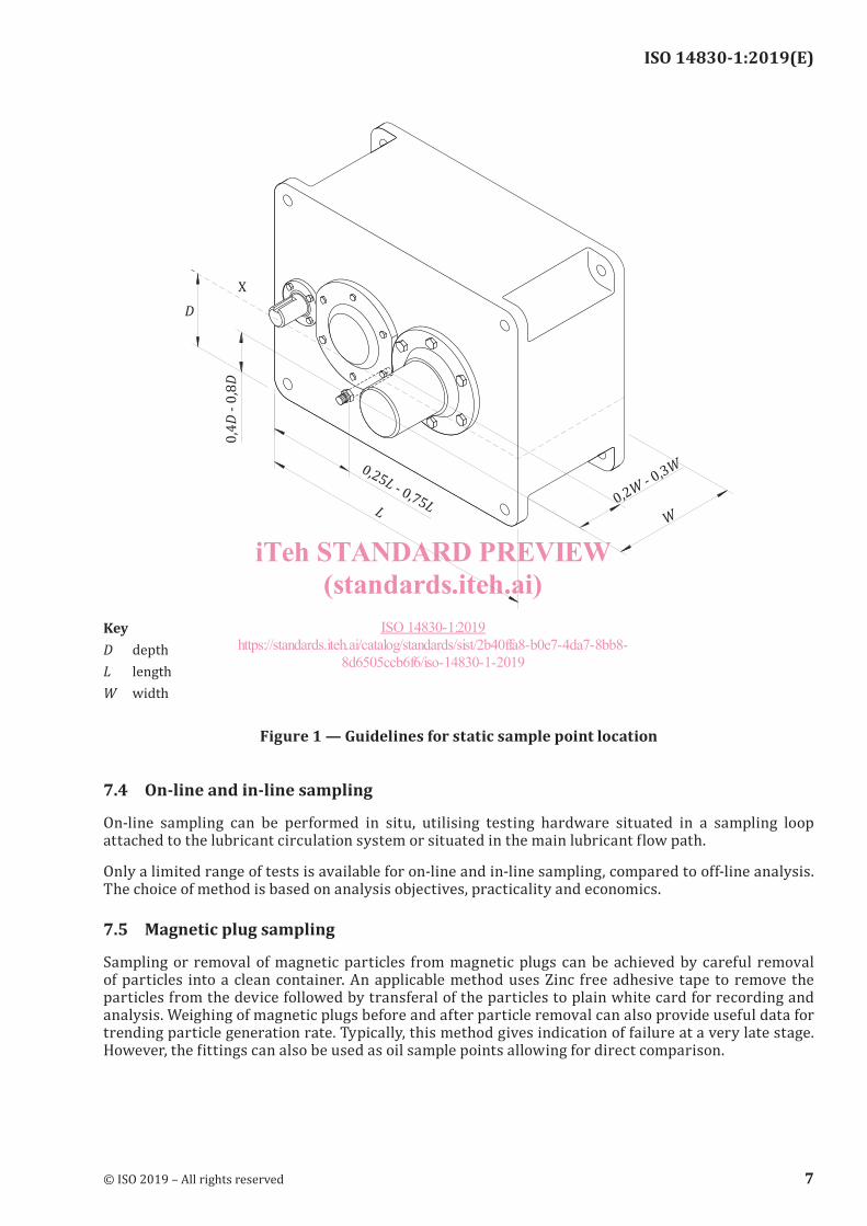
7.3 Static sample points
Static sampling from reservoirs, sumps, etc. may be used when dynamic sampling is not practicable, e.g. splash lubricated gearboxes and pumps:
a) Samples should be extracted from centralised areas in compartments where fluid is in motion, as close as possible to any oil return line and away from quiescent areas caused by corners and baffles. Fittings used should be well clear of moving parts and not interfere with compartment design flows.
b) Dedicated static sampling points are preferred. These include extension tubes inserted into the fluid bath from above and used with a vacuum pump, or valves inserted below fluid level.
c) Sample extraction using the vacuum pump and drop tube method is acceptable provided correct procedures are followed, inclusive of angled tube cutting and preservation of bottle cleanliness during sample extraction, and point locations comply with the other requirements of this document.
d) Points on level indicators and the like should only be used if they can be adequately (10 times the dead space) flushed prior to sampling.
e) The use of drain ports for sampling is discouraged, unless the analysis objectives can still be met.
f) Figure 1 gives guidelines for sample point location in a typical splash lubricated gearbox casing. Similar dimensions apply to hydraulic and lubrication system reservoirs, etc. Sample points will often need to be custom built or modified to achieve the requirements of this document for a particular compartment.
6 © ISO 2019 – All rights reserved
iTeh STANDARD PREVIEW(standards.iteh.ai)
ISO 14830-1:2019https://standards.iteh.ai/catalog/standards/sist/2b40ffa8-b0e7-4da7-8bb8-
8d6505ccb6f6/iso-14830-1-2019
ISO 14830-1:2019(E)
KeyD depthL lengthW width
Figure 1 — Guidelines for static sample point location
7.4 On-line and in-line sampling
On-line sampling can be performed in situ, utilising testing hardware situated in a sampling loop attached to the lubricant circulation system or situated in the main lubricant flow path.
Only a limited range of tests is available for on-line and in-line sampling, compared to off-line analysis. The choice of method is based on analysis objectives, practicality and economics.
7.5 Magnetic plug sampling
Sampling or removal of magnetic particles from magnetic plugs can be achieved by careful removal of particles into a clean container. An applicable method uses Zinc free adhesive tape to remove the particles from the device followed by transferal of the particles to plain white card for recording and analysis. Weighing of magnetic plugs before and after particle removal can also provide useful data for trending particle generation rate. Typically, this method gives indication of failure at a very late stage. However, the fittings can also be used as oil sample points allowing for direct comparison.
© ISO 2019 – All rights reserved 7
iTeh STANDARD PREVIEW(standards.iteh.ai)
ISO 14830-1:2019https://standards.iteh.ai/catalog/standards/sist/2b40ffa8-b0e7-4da7-8bb8-
8d6505ccb6f6/iso-14830-1-2019
ISO 14830-1:2019(E)
7.6 Grease sampling
The objectives of grease sampling remain to maximize data density and minimize data disturbance:
a) Samples should be representative of grease at component load zones.
b) Multiple sample locations can be required, particularly if components are large, or load zone location or wear characteristics vary.
c) Sampling should be carried out at identical locations, using identical methods to reduce variation.
8 Fluid sampling equipment
8.1 General
Equipment used to extract samples should not disturb their quality. It should be easy to use, clean, rugged and cost-effective.
8.2 Sample containers
Container cleanliness should conform to ISO 3722 to ensure representative samples are obtained, as summarised in Table 1.
Table 1 — Sample bottle cleanliness requirements
Sample bottle cleanliness class
(ISO 3722)
Max. no. of particles >10μm/ml
Sample bottle cleanliness target
(ISO 4406)
Lowest compartment cleanliness target
(ISO 4406)Clean 100 16/14/11 18/16/13
Superclean 10 13/11/8 15/13/10Ultraclean 1 9/7/4 11/9/6
Container volume shall provide a sufficient sample amount for the range of analysis tests to be performed, plus ullage space to allow for agitation. Materials used shall be compatible with the chemicals and temperatures likely to be encountered and not create additional hazards.
8.3 Sample tubing
Sample tubing should be clean and used only once. Flexible, clear, plastic derived material that is compatible with the chemicals and temperatures likely to be encountered is recommended.
Tubing diameter shall correspond to the sampling hardware and procedures used. It should be cut at a 45° angle, to the shortest length practicable for the application.
8.4 Manually operated hand held sample pumps
Manually operated hand held vacuum sample pumps should be designed for the purpose and kept clean internally and externally. If they become contaminated, dismantle and flush with clean white spirits or kerosene, filtered to the same cleanliness target as sample bottles they are used with. Do NOT use solvents or degreasers for flushing.
An area where sampling tools and equipment can be kept clean and in good working order should be designated.
8 © ISO 2019 – All rights reserved
iTeh STANDARD PREVIEW(standards.iteh.ai)
ISO 14830-1:2019https://standards.iteh.ai/catalog/standards/sist/2b40ffa8-b0e7-4da7-8bb8-
8d6505ccb6f6/iso-14830-1-2019
ISO 14830-1:2019(E)
8.5 Other equipment
The following additional equipment can be useful during lubricant sampling:
a) Previous analysis reports, sample route details, notebook and pens.
b) Pre-printed labels, felt tip pens or barcoded labels to mark/record samples.
c) Clean sample bottles and plastic tubing in individual zip lock bags.
d) Vacuum sample pump and sampling fittings in plastic bags.
e) Small torch, tape measure, plastic ties or electrical tape.
f) Tube cutter, multi tool, pocket knife or scissors. Shifting spanner.
g) Lint-free cloth, dust brush, scraper and cleaning solvent.
h) New clean lubricant for top-ups.
i) Container for waste flushing oil and used tubes, appropriately labelled.
j) Gloves and required personal protective equipment.
k) Bag, toolbox, trolley, etc. for carrying equipment.
Sampling of particles from magnetic plugs can be achieved by careful de-greasing and removal of particles using a non-metallic scraper into a clean container. Particle sampling can also be achieved by using Zinc free adhesive tape to remove the particles from the plug and then transferring the tape to plain white card.
8.6 Sample transport
All sample storage equipment shall be sealed from external contamination during transport and storage, protected from external environment and provided with secondary leak containment. The required sample accompanying documentation is given by country regulations for transport as applicable.
9 Sample analysis
9.1 General
Collected samples shall be analysed using predefined test suites, to provide measurements of desired lubricant and machine condition parameters. The process followed depends upon available analysis options.
9.2 On-site analysis
Testing may be performed using on-site facilities if available. Some on-site instruments use dielectric spectroscopy, voltammetry or infrared spectroscopy to detect changes in base oil and additive chemistry. Other on-site devices include portable sensors for moisture monitoring, contamination and wear particles analysis inclusive of morphology and image analysis. Commonly applied tests are discussed further in Annexes A and B.
On-site instruments and small workbench laboratories provide flexibility and convenience when instant information is needed. They typically cannot perform the full battery of tests that some complex situations require. However, bench level and portable instruments are important enabling technologies that offer time-critical information such as fluid contamination and wear particles analysis.
© ISO 2019 – All rights reserved 9
iTeh STANDARD PREVIEW(standards.iteh.ai)
ISO 14830-1:2019https://standards.iteh.ai/catalog/standards/sist/2b40ffa8-b0e7-4da7-8bb8-
8d6505ccb6f6/iso-14830-1-2019