Embed Size (px)
Citation preview

Cooling, conditioning, purifying.
EHC
GY
000D
Ied
. 06/
2007
Conditioning your ambient, maximising your comfort.
CYGNUSCYGNUS HCYGNUS CYGNUS/MC HCYGNUS/MC
Refrigeratori di liquido condensati ad aria, pompe di calore,motocondensanti e motocondensanti reversibili
(Potenza frigorifera 4-66kW, potenza termica 5-70kW, compressori rotativi e scroll)
Air-cooled liquid chillers, heat pumps, condensing units and reversible condensing units(Cooling capacity 4-66kW, heating capacity 5-70kW, rotary or scroll compressors)
R407C 50Hz

Conditioning your ambient,maximising your comfort.
Cooling, conditioning, purifying.

Specifiche tecnicheTechnical specifications
Guida alla selezioneSelection guide
Prestazioni e dati tecniciPerformance and technical data
Limiti di funzionamento, coefficienti correttiviOperating limits, correction factors
Perdita di carico evaporatoreEvaporator pressure drops
Disegni di ingombroOverall dimensions
Guida all’installazioneInstallation guide
2
7
10
36
38
39
44
Conditioning your ambient, maximising your comfort.
CYGNUS
Indi
ce -
Ind
ex

CY
GN
US
SPECIFICHE TECNICHE - TECHNICAL SPECIFICATIONS
1. General
The packaged chillers, heat pumps, condensing units and reversiblecondensing units in the Cygnus series are designed for outdoor installation: air-cooled, with hermetic rotary compressors (first threemodels) and scroll compressors, finned core condenser and axial fanswith rotary speed modulation. Chillers and heat pumps are equippedwith a stainless steel brazed plate evaporator, water circulator or centrifugal pump according to the model, and water storage tank. The units are administrated by a microprocessor controller with fullyindependent management of all the main functions, including controls, alarms and interface with the periphery. The units use R407Crefrigerant.All the units are designed, built and checked in compliance with ISO9001, using components sourced from premium manufacturers.All the data presents in this catalogue refers to the standards units atthe nominal conditions of working (except when differently specified).
2. Nameplate
Machines are identified by their nameplate:
CG/HCG/CGMC/CGHMC XXX
Cooling circuit n° (1 for this series)
Cooling compressor indicative power in HP
CYGNUS - HCYGNUS - CYGNUS/MC - CYGNUS/HMC
Note: for the models from 013 to 020 only the compressor power inHP multiplied by ten is indicated.
3. Testing
Each unit is tested in a test chamber in order to check correct operationboth in the most representative operating conditions and in the mostdemanding conditions; the following aspects are checked in particular:- correct installation of all components and the absence of refrigerant
leaks;- electrical safety tests are performed as prescribed by CEI EN60335-1
and CEI EN60335-2-40;- correct operation of the microprocessor controller together with the
value of all operating parameters;- temperature probes and pressure transducers;- operation is forced at nominal conditions in order to check:
calibration of the thermostatic valve, the refrigerant charge, evaporation and condensing temperatures, superheating and subcooling, cooling capacity output;
1. Generalità
I refrigeratori di liquido, le pompe di calore monoblocco, le motocondensanti e motocondensanti reversibili della serie Cygnussono unità progettate per uso in ambiente esterno condensate ad aria,con compressori ermetici rotativi (primi tre modelli) e scroll, condensatore a pacco alettato e ventilatori assiali con modulazionedella velocità di rotazione. Refrigeratori di liquido e pompe di caloresono equipaggiati con evaporatore a piastre saldobrasate in acciaioinox, circolatore d’acqua o pompa centrifuga a seconda dei modelli e serbatoio idraulico inerziale. La gestione é affidata ad un controllo a microprocessore che gestisce,in totale autonomia, tutte le funzioni principali, tra cui, regolazioni,allarmi ed interfaccia con l’esterno. Il fluido frigorigeno utilizzato èl’R407C. Tutte le macchine sono progettate, prodotte e controllate inconformità alle norme ISO 9001, con componenti di primaria marca.Tutti i dati riportati in questo catalogo sono riferiti a macchine standarde a condizioni nominali di funzionamento (salvo quando diversamentespecificato).
2. Sigla
Le macchine sono identificate dalla sigla:
CG/HCG/CGMC/CGHMC XXX
N° circuiti refrigerante (per questa serie = 1)
potenza nominale assorbita dal compressore frigorifero in HP
CYGNUS - HCYGNUS - CYGNUS/MC - CYGNUS/HMC
Nota: nei modelli dal 013 al 020 viene indicata solamente la potenzain HP del compressore moltiplicata per dieci.
3. Collaudo
Ogni macchina prodotta viene collaudata in cabina di controllo pervalutarne il corretto funzionamento, sia nelle condizioni operativepiù significative, che in quelle più gravose; in particolare:- si verifica il corretto montaggio di tutti i componenti e l’assenza di
fughe di fluido refrigerante;- si eseguono i test di sicurezza elettrici come prescritto dalle CEI
EN60335-1 e CEI EN60335-2-40;- si verifica il corretto funzionamento del controllo a microprocessore
ed il valore di tutti i parametri d’esercizio;- si verificano le sonde di temperatura ed i trasduttori di pressione;- forzando il funzionamento alle condizioni nominali si verificano: la
taratura della valvola termostatica, la carica di fluido frigorigeno, le temperature di evaporazione e di condensazione, il surriscaldamentoed il sottoraffreddamento, la potenza frigorifera resa;
®
1. Generalità2. Sigla3. Collaudo4. Compressori5. Evaporatore6. Batterie condensanti7. Elettroventilatori8. Circuito Frigorifero9. Struttura e Carenature10. Quadro elettrico di potenza e controllo11. Gruppo idraulico12. Controllo e gestione
2
1. General2. Nameplate3. Testing4. Compressors5. Evaporator6. Condenser coil7. Fans motor8. Cooling circuit9. Structure and casing10. Power and control electrical panel11. Hydraulic group12. Control and management

CY
GN
US
®
3
- il collaudo delle pompe di calore avviene sia in modalità raffredda-mento che riscaldamento.
All’atto dell’installazione le macchine richiedono solo le connessionielettriche ed idrauliche, e per le versioni motocondensanti il collegamento ad uno scambiatore remoto, assicurando un alto livellodi affidabilità.
4. Compressori
I compressori impiegati sono di tipo ermetico: rotativo con separatore d’aspirazione integrato per i modelli 013-015-020 e scrollper tutti gli altri; in particolare i modelli 211-251-301 utilizzano due compressori collegati in parallelo nello stesso circuito. I compressoridelle versioni pompa di calore e di tutte le unità motocondensantisono dotati di resistenza di riscaldamento carter. I compressori ermetici impiegati presentano numerosi vantaggi tra i quali: ridotteperdite di carico in aspirazione grazie all’assenza di valvole, granderesistenza agli eventuali colpi di liquido, elevato rendimento di compressione, elevata aspettativa di vita con manutenzione inesistente, bassissime vibrazioni e livello di rumorosità. Gli avvolgimenti del motore elettrico sono a 2 poli e sono protetti dallesovratemperature, derivanti da un’eventuale funzionamento anomalo,da un termocontatto nei compressori rotativi e da un modulo elettronicointegrato negli scroll. Sono sempre montati su antivibranti in gomma, esono installati in un vano acusticamente isolato tramite materassinofonoassorbente bugnato.
Opzionale:- resistenza carter compressore nella versione chiller solo freddo.
5. Evaporatore
L’evaporatore è a piastre in acciaio inox saldobrasate con rame ed èposizionato nel vano compressori. Questi evaporatori sono estremamente efficienti e compatti e richiedono pertanto pochissimospazio per l’alloggiamento all’interno dell’unità a tutto vantaggio dell’accessibilità interna. Sono protetti dal pericolo di ghiacciamento,causato da eventuali basse temperature di evaporazione, dalla funzione antigelo della centralina elettronica che controlla la temperatura di uscita dell’acqua. Inoltre ogni evaporatore monta unpressostato differenziale che lo protegge dalla mancanza di flussod’acqua. Sarà cura dell’installatore inserire un filtro in ingresso allamacchina per intercettare eventuale sporcizia che andrebbe a depositarsi nel serbatoio o nell’evaporatore. Tutti gli evaporatori impiegati nelle versioni Cygnus e HCygnus rispettano la normativa“CE” riguardante i recipienti in pressione e possono trattare soluzioni anticongelanti e, in generale, altri liquidi che risultino compatibili coni materiali costituenti il circuito idraulico.
Opzionale:- resistenza antigelo (montata attorno all’evaporatore, pompa e
serbatoio d’accumulo) comandata dalla centralina elettronica a bordo macchina in funzione della temperatura aria esterna.
6. Batterie condensanti
Sono batterie a pacco alettato, “sdoppiate” sui due lati dell’unità neimodelli dal 081 al 301, sono costituite da tubi e collettori in rame,alette corrugate in alluminio e spalle in lamiera zincata. Questi scambiatori sono stati calcolati, dimensionati e disegnati utilizzandomoderne tecniche di progettazione al computer. Le batterie sono realizzate su soli 2 o 3 ranghi, a seconda del modello, permettendol’utilizzo di ventilatori a basso numero di giri e garantendo un ulteriore miglioramento delle prestazioni sonore della macchina. Lebatterie condensanti, nella versione pompa di calore, sono dotate di“ragno” distributore per una corretta alimentazione dei circuiti refrigerante. Inoltre, per migliorare il deflusso dell’acqua di condensadurante il ciclo di sbrinamento, le batterie sono posizionate con l’estremità inferiore delle alette rialzata rispetto al piano di appoggio.
- testing of heat pumps is performed in both cooling and heating mode.
At the time of installation the units require exclusively electrical andhydraulic connections, and, in the case of condensing unit versions,connection to a remote exchanger, ensuring a high level of reliability.
4. Compressors
The compressors are hermetic: rotary type with integral separator onsuction side for models 013-015-020 and scroll type for the remaining models; in particular, models 211-251-301 are equippedwith two compressors connected in parallel in the same circuit.Compressors of the heat pump versions and on all condensing units areequipped with crankcase heaters.Hermetic compressors offer a series of benefits, including: reduced pressure drops on the suction side thanks to the absence of valves; elevated resistance to possible liquid pressure shocks, high compression efficiency, long lifetime with zero maintenance, and verylow level of vibration and noise emissions. The 2-pole motor windings are protected against overheating caused by possible malfunctions by a thermal cut-out in rotary compressors and by an electronic integrate module in scroll versions.In this series the compressors are secured by means of rubber antivibration mounts and housed in a compartment that is acousticallyinsulated with textured sound absorbing matting.
Optional:- compressor crankcase heater in cooling-only chiller version.
5. Evaporator
The stainless steel brazed plate evaporator is housed in the compressorcompartment. These evaporators are highly efficient and compact andtake up only minimum space inside the unit, with consequent benefitsin terms of internal accessibility. They are protected from the risk offreezing, potentially caused by low evaporation temperatures, bymeans of an antifreeze function incorporated in the electronic controller involving supervision of the water outlet temperature. Inaddition, each evaporator is equipped with a differential pressure switch to protect it if the water flow should be missing or insufficient.The installer should fit a filter on the unit inlet to intercept any debrisin the water supply that would otherwise accumulate in the tank or inthe evaporator.All evaporators in the Cygnus and HCygnus versions comply with theEC pressure vessels directive and can handle antifreeze solutions and,in general, all other liquids that are compatible with the hydraulic circuit construction materials.
Optional:- antifreeze heating element (wrapped around evaporator, pump and
storage tank) controlled by the on-board electronic controller in accordance with ambient air temperature.
6. Condenser coils
Finned core type condensing coils – “on both sides” of the unit inmodels 081 to 301, are composed of copper tubes and headers, aluminium corrugated fins and galvanized sheet metal shoulders.These exchangers are calculated, sized and designed utilising the latest CAD techniques. The coils have just 2 or 3 rows, depending onthe model, thus allowing the use of low speed fans and guaranteeingan additional reduction in noise levels. In the heat pump version thecondensing coils are equipped with a “distributor device” for correctsupply of the refrigerant circuits. Moreover, to improve the drainage of condensate during defrost cyclesthe coils are positioned with the lower edge of the fins raised withrespect to the supporting surface.

4
®Kit di vendita:- filtri a rete metallica di protezione delle batterie.
Forniti come speciali:- batterie preverniciate.
7. Elettroventilatori
Tutte le versioni della serie Cygnus sono equipaggiate con ventilatoriassiali a bassa velocità di rotazione (minore di 900 giri/minuto). Imodelli dal 013 al 071, con flusso d’aria orizzontale, e dal modello131 al 171 impiegano ventilatori con pale in materiale plastico; dalmodello 013 allo 071 i convogliatori sono in polistirolo ad alta densità, i rimanenti modelli utilizzano ventilatori con pale a falce inalluminio pressofuso, ed il boccaglio è realizzato direttamente nellalamiera del tetto. Convogliatori e boccagli sono sagomati per ottimizzare le prestazioni aerauliche e sonore del gruppo motoventilante. Sono dotati di griglia di protezione antinfortunistica eregolazione elettronica continua, a taglio di fase, sia per il controllo della pressione di condensazione che per la riduzione dell’emissione sonora nelle più frequenti condizioni operative. I motori elettrici incorporano la protezione dai sovraccarichi e, perassicurare il funzionamento all’esterno con tutti i climi, il grado di protezione è IP44 per i ventilatori in materiale plastico e IP54 perquelli con pale in alluminio, con classe di isolamento F.
8. Circuito frigorifero
Il circuito frigorifero delle versioni compatte CG e H-CG, nella loroconfigurazione standard, si completa nel seguente modo:- filtro deidratatore;- capillare di espansione (modelli solo freddo dal 013 al 020);- valvola termostatica (modelli solo freddo dal modello 031 al 301 e
tutte le pompe di calore;- pompe di calore con 2a valvola termostatica per l’ottimizzazione
delle prestazioni in tutti i regimi di funzionamento (modelli 131 al 301);
- spia di flusso (tutte le pompe di calore e modelli solo freddo dal 031 al 301);
- ricevitore di liquido (tutte le pompe di calore);- valvola a quattro vie di inversione del ciclo frigorifero, nelle
versioni pompa di calore;- olio anticongelante e carica refrigerante.
Tutte le brasature per il collegamento dei vari componenti sono eseguite con lega di argento ed i tubi di rame sono rivestiti di materiale termoisolante nelle parti fredde per evitare la formazione dicondensa.
La versione motocondensante CG/MC è realizzata a partire dallo versione chiller CG eliminando il gruppo idraulico, l’evaporatore e lavalvola termostatica ed aggiungendo una valvola solenoide sulla lineadel liquido ed i rubinetti sulla linea del liquido e sulla linea del gasall’uscita della macchina. La versione motocondensante reversibile HCG/MC è realizzata a partire dalla versione compattapompa di calore HCG eliminando il gruppo idraulico, l’evaporatoreed il ricevitore di liquido, montando una termostatica (per il funzionamento in regime di riscaldamento), aggiungendo un separatore di liquido in aspirazione compressore (eccetto i primi tremodelli che lo montano di serie) ed i rubinetti sulla linea del liquidoe sulla linea del gas alle uscite della macchina. Le versioni motocondensante e motocondensante reversibile sono dotate di pre-carica di refrigerante che dovrà essere completata in fase di installazione e collegamento all’impianto.
Il dimensionamento e la realizzazione delle linee refrigeranti di collegamento tra unità motocondensante e unità evaporante, è diestrema importanza per garantire il corretto funzionamento insicurezza del sistema, e perciò deve essere eseguito da personale qualificato seguendo le indicazioni ed i dimensionamenti suggeriti daMTA.
Sales kits:- metal mesh coil protection filters.
Supplied as special options:- prepainted coils.
7. Fan motors
All versions in the Cygnus series are equipped with reduced speedaxial fans (speed less than 900 rpm). Models 013 to 071, with horizontal air flow, and models 131 to 171, use fans with plastic blades; on models 013 to 071 the fan shrouds are made of high density polystyrene, while the remaining models use fans with die-cast aluminium sickle-shaped blades, while the port is createddirectly in the sheet metal roof panel. Shrouds and ports are suitablyshaped to optimise air handling and acoustic performance of the fanunit. The fans are equipped with a safety grille and phase cut-off typecontinuous electronic control, both for the control of condensing pressure and to reduce noise levels in the most frequent duty conditions.The electric motors feature built-in overload protection and, in orderto ensure outdoor operation in all climates, the protection rating isIP44 for plastic vane and IP54 for aluminium vane fans, with insulation class F.
8. Cooling circuit
The refrigerant circuit in the standard configuration of the CG and H-CG compact versions is completed as follows:- filter-dryer;- expansion capillary tube (cooling-only models 013 to 020);- thermostatic valve (cooling-only models 031 to 301 and all heat
pumps);- heat pumps with 2nd thermostatic valve for optimisation of
performance in all operating conditions (models 131 to 301);
- liquid flow sight glass (all heat pumps and cooling-only models 031to 301);
- liquid receiver (all heat pumps);- 4-way refrigerant cycle reversing valve, in heat pump versions;
- non-freezing oil and refrigerant charge.
All brazing for connections of components is performed using silveralloy and cold sections of the copper tubes are clad with insulatingmaterial to prevent the formation of condensation.
The CG/MC condensing unit version is available from the CG chillerversion eliminating the hydraulic unit, evaporator and thermostaticvalve and adding a solenoid valve on the liquid line and shut-off cockson the liquid line and gas line at the outlet from the unit.The HCG/MC reversible condensing unit version is available from thecompact HCG heat pump version, eliminating the hydraulic unit, evaporator and liquid receiver, and installing a thermostatic valve (foroperation in heating mode), adding a liquid separator on the compressor suction side (with the exception of the first three modelswhich are equipped with the liquid separator as standard) and shut-offcocks on the liquid line and on the gas line at the outlet from the unit.The condensing unit and reversible condensing unit versions areequipped with a refrigerant pre-charge which must be completed atthe time of installation and connection to the building system.
Sizing and installation of the refrigerant lines connecting the condensing unit and evaporator unit are of the utmost importance toguarantee correct and safe operation of the system; these operationsmust therefore be carried out by qualified personnel in strict observance of the indications and sizes recommended by MTA.
CY
GN
US

CY
GN
US
®
5
9. Struttura e carenature
Tutto il basamento, i montanti e le carenature sono realizzati conlamiera di acciaio al carbonio zincata, sottoposta ad un trattamento difosfosgrassaggio e verniciatura a forno a 180 °C con polveri poliesteriche conferiscono un’alta resistenza agli agenti atmosferici. Il colore della base é blu RAL 5013P ad effetto bucciato, il colore delresto della struttura e della pannellatura é grigio chiaro RAL 7035P adeffetto bucciato. La struttura è stata studiata per accedere facilmente atutti i componenti della macchina e l’unione delle varie parti è realizzata con viti di acciaio zincato.
Kit di vendita:- kit antivibranti;- piatto esterno di raccolta della condensa con attacco portagomma
abbinabile ai soli modelli dal 013 al 071.
10. Quadro elettrico di potenza e controllo
L’unità ed il quadro elettrico sono realizzati in conformità alla normaCEI EN60335-1 (Sicurezza degli apparecchi elettrici d’uso domesticoe similare – Sicurezza Parte 1: Norme generali) ed alla norma CEIEN60335-2-40 (Sicurezza degli apparecchi elettrici d’uso domesticoe similare – Sicurezza Parte 2: Norme particolari per le pompe dicalore elettriche, per i condizionatori d’aria e per i deumidificatori);in particolare viene garantita la protezione contro gli agenti atmosferici necessaria per l’installazione dei refrigeratori all’esterno(grado di protezione IP X4). Il quadro elettrico è dotato di sezionatore generale con dispositivoblocca-porta, e contiene le protezioni dei dispositivi di potenza, tra iquali: fusibili per la protezione dei compressori dei modelli dal 013al 020, e interruttori automatici dal modello 031 al 301; fusibili per laprotezione di tutti i ventilatori; interruttori automatici magnetotermiciper la protezione termica e dal cortocircuito delle pompe centrifughedei modelli dal 031 al 301; i circolatori dei modelli dal 013 al 020utilizzano una termocoppia integrata al circolatore stesso per laprotezione termica, ed un fusibile per la protezione dal cortocircuito;deviatore per la commutazione manuale delle due pompe, quandoscelta l’opzione 2a pompa in stand-by. La sezione di controllocomprende il trasformatore per l’alimentazione degli ausiliari (24 V) ela scheda a microprocessore.
Kit di vendita:phase monitor.
11. Gruppo idraulico
Le unità compatte CG e HCG integrano il modulo di pompaggio eaccumulo costituito da:- serbatoio inerziale di capacità adeguata alla potenza frigorifera
nominale, posizionato sul ritorno dall’impianto, costruito in acciaioal carbonio e coibentato esternamente con isolante termico e anticondensa;
- circolatore (dal modello 013 al 020) o pompa centrifuga (dal modello 031 al 301);
- valvola di drenaggio/caricamento;- valvola di sfiato manuale;- pozzetti per la misura della temperatura di ingresso/uscita acqua
evaporatore;- vaso di espansione;- valvola di sicurezza da 3 barg;- manometro acqua posizionato sulla mandata della pompa, in modo
da indicare la pressione di precarico dell’impianto (a refrigeratore spento) o la pressione di mandata della pompa (a refrigeratore acceso);
- pressostato differenziale, blocca il funzionamento del compressore in caso di mancato flusso dell’acqua attraverso la parte idraulica;
9. Structure and casing
The plinth, uprights and outer panels are made of galvanized carbonsteel sheet subjected to a phosphor degreasing treatment and paintedwith a polyester powder coating baked-on at 180 °C to provide a durable weatherproof finish. The plinth is finished in orange-peel blue(RAL 5013P), while the remaining parts of the frame and panels arefinished in orange-peel light grey (RAL 7035P).The unit frame is designed to ensure easy access to all internal components, with the various members of the structure assembled bymeans of galvanized steel screws.
Sales kits:- antivibration mounts kit;- external condensate tray with hose connection, for use exclusively
with axial fan condensing unit model from 013 to 071.
10. Power and control electrical panel
The unit and the electrical cabinet are made in compliance with CEIEN60335-1 (Household and similar electrical appliances – Safety Part1: General provisions) and CEI EN60335-2-40 (Household andsimilar electrical appliances - Safety Part 2: Special provisions forelectric heat pumps, air conditioners, and dehumidifiers); inparticular, weather protection is ensured to allow the chillers to beinstalled outdoors ( protection grade IPX4).The electrical cabinet is equipped with a main disconnect switch withdoor-lock device, and it accommodates the protections for the powerdevices, including: fuses to protect the compressors of models 013 to020, and automatic cut-outs from model 031 to 301; fuses for theprotection of all fans; thermal-magnetic cut-outs for thermal andshort-circuit protection of the centrifugal pumps in models 031 to301; the circulators of models 013 to 020 are equipped with athermocouple incorporated in the pump itself to provide thermalprotection, and a fuse for short-circuit protection; selector for manualchangeover between the two pumps; when the option is selected the2nd pump is in stand-by.The control section includes the transformer for the 24V controlcircuits and the microprocessor board.
Sales kits:phase monitor.
11. Hydraulic group
The CG and HCG compact units are equipped with the pumpingand storage tank module composed of:- storage tank with suitable capacity in relation to the nominal
cooling capacity, installed on the return line from the system, madeof carbon steel and externally insulated with thermal insulation andanti-condensation cladding;
- circulator (models 013 to 020) or centrifugal pump (models 031 to 301);
- drain/filling valve;- manual bleed valve;- test points on the evaporator inlet/outlet lines for water temperature
measurements;- expansion vessel;- 3 barg relief valve;- water pressure gauge on the pump pressure line, to show the
system pre-charge pressure (with chiller off) or the pump delivery pressure (with chiller on);
- differential pressure switch to inhibit compressor operation in the case of the absence of water flow through the hydraulic section;

®
6
Opzionale:- circolatore/pompa con prevalenza utile ridotta, disponibile per
tutti i modelli ad esclusione di quelli dal 031 al 071;- 2a pompa in stand-by con commutazione manuale e rubinetti di
intercettazione a monte e a valle di ciascuna pompa, disponibile dal modello 081 per le versioni CG e 131 per le versioni HCG.
- versione con solo modulo di pompaggio; rispetto alla versione con modulo completo, non monta il serbatoio inerziale (vd anche termostatazione autoadattativa nel capitolo “Controllo e gestione”).
12. Controllo e gestione
Il controllo e la gestione della macchina sono affidati alla centralinaelettronica “DIXELL IC121” con esclusiva visualizzazione dei parametrisu doppio display e identificazione delle funzioni tramite icone. Oltre alle normali operazioni di on/off impianto, commutazione estate-inverno (pompe di calore) e modifica del set-point di funziona-mento, la semplicità di utilizzo permette a qualsiasi utente di variare iprincipali parametri di funzionamento del sistema.
La centralina gestisce in totale autonomia le seguenti funzioni:- cicli di accensione dei compressori, temporizzazione e, nelle unità
a due compressori, equalizzazione dei loro tempi di funzionamento;- unloading nelle unità a due compressori, che permette l’avviamento
dell’impianto, ed il funzionamento della macchina, anche a condizionimolto differenti da quelle nominali;
- regolazione della velocità dei ventilatori in funzione della pressione di condensazione, per migliorare le prestazioni acustichenelle condizioni di funzionamento meno gravose, e mantenere la pressione di condensazione entro i limiti richiesti dal compressore;
- controllo antigelo in funzione della temperatura di uscita acqua dall’evaporatore;
- funzione FDS (Frost Detecting System) che, grazie al monitoraggio continuo del rendimento dell’evaporatore, attiva i cicli di sbrinamentodelle pompe di calore solo quando effettivamente necessari, consentendo così una maggiore efficienza energetica dell’impiantorispetto alle logiche di sbrinamento tradizionali;
- termostatazione autoadattativa (sempre attivata) che, tramite la modifica dinamica del set-point, consente il funzionamento del chiller in condizioni di basso carico termico e ridotto volano idraulico;
- gestione dei messaggi d’allarme, tra i quali:• allarme bassa pressione evaporazione;• allarme alta pressione condensazione;• allarme flusso acqua;• allarme di intervento del pressostato differenziale per mancanza
acqua all’evaporatore;• allarme antigelo.
Le versioni motocondensanti mantengono la centralina di controllo;l’utilizzatore può controllare le temperature dello scambiatore remoto tramite le sonde standard a bordo unità, remotandole fino adun massimo di 100 metri, oppure utilizzare un proprio sistema di controllo utilizzando gli appositi ingressi digitali del controllo.
Kit di vendita:- display remoto replicato “DIXELL VI610S” per la gestione a
distanza (150 m) dell’unità;- Kit supervisione XWEB300;- Kit supervisione RS 485;- Kit supervisione Modem GSM per supervisione XWEB300.
Optional:- circulator/pump with reduced pressure head, available for all models
with the exception of models 031 to 071;- 2nd pump in stand-by with manual changeover and shutoff
valves on each pumps upstream and downstream, available from model 081 for CG versions and 131 for HCG versions.
- version with pumping module only; unlike the version with the complete module, this version is not equipped with the storage tank(see also self-adaptive temperature control in the chapter “Control and management”).
12. Control and management
Control and management of the unit are provided by the “DIXELLIC121” electronic controller with exclusive presentation of parameterson the dual display and icon-based identification of functions. Apartfrom the normal system on/off operations, switching between summerand winter set-ups (heat pumps), and modifying the operating setpoint,this controller is so straightforward that even inexperienced users canmodify the main system operating parameters.
The controller manages the following functions independently:- compressor start cycles, timing and, in two-compressor units,
equalisation of run times;- unloading valve in dual-compressor units, for system start and unit
operation also in conditions that differ greatly from the nominal conditions;
- fans speed control in relation to condensing pressure to reduce noise emissions in less demanding conditions and maintain condensing pressure within the limits required by the compressor;
- antifreeze control in accordance with the water temperature at the evaporator outlet;
- FDS (Frost Detecting System) function, which, through constant monitoring of evaporator efficiency, starts defrost cycles on heat pumps only when they are effectively necessary, making it possibleto achieve maximum energy efficiency of the system compared to the use of conventional defrost logic;
- self-adaptive temperature control (always on) which, by means of dynamic modification of the set-point, allows chiller operation in conditions of low thermal loads and reduced hydraulic inertia;
- management of alarm messages, including:• low evaporation pressure alarm;• high condensing pressure alarm,• water flow alarm; • differential pressure switch trip alarm due to insufficient or zero
water flow to the evaporator;• anti-freeze alarm.
Condenser unit versions retain the control unit; the user can check theremote exchanger temperatures by means of the standard probes on-board the unit, which can be remotised up to 100 metres (max.), or usea proprietary control system by means of the specific digital inputsprovided on the controller.
Sales kits:- replicated remote control “DIXELL VI610S” for remote management
(up to 150 m) of the unit;- XWEB300 supervision kit;- RS 485 supervision kit;- GSM modem supervision kit for XWEB300 supervision.
CY
GN
US

CY
GN
US
GUIDA ALLA SELEZIONE - SELECTION GUIDE
®
7
La selezione di una macchina viene eseguita tramite la tabella “Guidaalla selezione” e tramite le Tabelle Dati relative a ciascuna singolamacchina.
Per una corretta selezione di un modello di macchina è necessario,inoltre:
1) Verificare che siano rispettati i limiti di funzionamento indicati nella tabella “Limiti di funzionamento”.
2) Verificare che la portata d’acqua da raffreddare o riscaldare sia compresa tra i valori di portata minima e massima indicati nella tabella “Dati generali” di ciascuna macchina; valori di portata troppo bassa comportano un flusso laminare e, di conseguenza, pericolo di ghiacciamento ed una cattiva regolazione; al contrario valori di portata troppo elevati comportano eccessive perdite di carico, e possibilità di rottura dei tubi dello scambiatore di calore acqua/refrigerante.
3) Prevedere l’aggiunta di glicole etilenico o di altri liquidi anticongelanti per utilizzi della macchina al di sotto di 0 °C; consultare la tabella “Soluzioni di acqua e glicole etilenico” per determinare la quantità di glicole etilenico necessaria e per valutare la riduzionedi resa frigorifera/potenza termica, l’aumento di potenza assorbita dai compressori, l’aumento delle perdite di carico allo scambiatore acqua/refrigerante a causa della presenza del glicole etilenico.
4) Qualora la macchina venga installata ad una altitudine maggiore di 500 m. valutare la riduzione di resa frigorifera/potenza termica e l’aumento di potenza assorbita dal compressore tramite i coefficienti indicati nella tabella “Coefficienti correttivi scambiatoredi calore aria/refrigerante”.
5) Qualora la differenza di temperatura fra ingresso e uscita acqua sia diversa da 5 °C correggere la potenza frigorifera/potenzatermca e la potenza assorbita utilizzando la tabella “coefficienti correttivi ∆T ≠ 5 °C.
For the selection of a chiller use the table “Guide to the selection” andthe table “Data Charts” relative to each unit.
For a correct chiller selection it is also necessary:
1) Observe the operational limits as indicated in the chart “Limits of operation”.
2) Verify that the cool water flow is between the minim and maximumvalues of water flow, which are described in the “General Data” table. A very low flow can cause laminar flow and thus danger of ice formation and poor unit control; a very high flow can cause great pressure drops and the possibility of tube failure inside the evaporator.
3) For working temperatures under 0 °C it is necessary to add ethylene glycol or any other antifreeze liquids.Consult the chart “Solutions of water and glycol” to determine the necessary quantity of ethylene glycol, the reduction of cooling/heating capacity, the increase of power absorbed by the compressors, the increase of evaporator pressure drop due to the presence of the ethylene glycol.
4) If the chiller is to be installed at an altitude higher than 500 m, youmust calculate the cooling/heating capacity reduction and the
increase of power absorbed by the compressor through the coefficients as pointed out in the chart “Condenser corrective coefficients”.
5) When the difference in temperature between water inlet and outlet is different from 5 °C, the cooling/heating capacity and the absorbed power must be connected using the table “Corrective coefficients ∆T ≠ 5 °C”.

(1) Temperatura aria esterna massima, riferita alla temperatura ingresso acqua refrigerata: 12 °C, uscita acqua refrigerata: 7 °C. Maximum external airtemperature, refer to cooled water inlet 12 °C and outlet water temperature condition at 7 °C.
(2) Potenza frigorifera alla temperatura aria esterna massima. Cooling capacity refer to the maximum external air temperature.(3) Temperatura aria esterna minima, riferita alla temperatura ingresso acqua: 40 °C e temperatura uscita acqua 45 °C. Minimum external air
temperature, refer to water inlet temperature 40 °C and outlet water temperature condition at 45 °C.(4) Potenza termica alla temperatura aria esterna minima. Heating capacity refer to the minimum external air temperature.
Per selezionare il modello di refrigeratore è necessario scegliere la colonna indicante la temperatura aria esterna massima in cui il refrigeratore saràinstallato e la riga con la potenza frigorifera richiesta. Le rese indicate nella tabella sono riferite alle seguenti condizioni: ingresso acqua refrigerata:12 °C, uscita acqua refrigerata: 7 °C. Per condizioni diverse e per le altre caratteristiche della macchina consultare le tabelle interne relative al modello selezionato. To select the chiller model you must choose the column that indicates the maximum external air temperature in which the chillerwill be installed and the line with the cooling capacity requested. The capacities shown in the table refer to the following conditions: cooled waterinlet 12 °C and cooled water outlet 7 °C. For other conditions and other unit specifications, consult the internal tables relative to the model selected.
Per selezionare il modello di pompa di calore è necessario scegliere la colonna indicante la temperatura aria esterna minima in cui la pompa di calore sarà installata e la riga con la potenza termica richiesta. Le potenze termiche indicate nella tabella sono riferite alle seguenti condizioni: temperatura ingresso acqua: 40 °C, temperatura uscita acqua: 45 °C. Per condizioni diverse e per le altre caratteristiche della macchina consultare letabelle interne relative al modello selezionato. To select the heat pump model you must choose the column that indicates the minimum external air temperature in which the heat pump will beinstalled and the line with the capacity requested. The capacities shown in the table refer to the following conditions: water inlet temperature 40 °Cand water outlet temperature 45 °C. For other conditions and other unit specifications, consult the internal tables relative to the model selected.
®
8
POTENZA FRIGORIFERA - COOLING CAPACITY (kW)
temperatura aria esterna - external air temperature (°C)
27 30 32 35 38 43CG 013 4.24 4.18 4.14 4.07 3.98 3.82CG 015 5.15 5.02 4.94 4.80 4.66 4.42CG 020 7.59 7.33 7.17 6.92 6.68 6.29CG 031 10.5 10.2 10.0 9.74 9.43 8.89CG 051 14.4 14.1 13.8 13.5 13.2 12.8CG 071 17.6 17.2 17.0 16.7 16.3 15.6CG 081 23.0 22.3 21.9 21.2 20.4 19.1CG 101 31.3 30.3 29.6 28.5 27.4 25.4CG 131 40.6 39.3 38.5 37.1 35.7 33.3CG 171 47.9 46.5 45.4 43.8 42.2 39.3CG 211 54.4 52.7 51.6 49.8 48.0 44.8CG 251 62.5 60.5 59.1 57.0 54.8 50.9CG 301 71.4 69.3 67.8 65.5 63.1 58.9
t max (1)
(°C)47474647464547464646464645
Pf (2)
(kW)3.674.226.048.4312.615.317.924.131.737.542.848.557.1
CG
POTENZA FRIGORIFERA - COOLING CAPACITY (kW)
temperatura aria esterna - external air temperature (°C)
27 30 32 35 38 43HCG 013 4.02 3.98 3.94 3.87 3.79 3.64HCG 015 4.80 4.68 4.59 4.46 4.32 4.08HCG 020 7.17 6.92 6.76 6.53 6.29 5.91HCG 031 10.1 9.78 9.59 9.30 9.01 8.48HCG 051 13.6 13.3 13.0 12.7 12.4 12.0HCG 071 16.7 16.5 16.3 15.9 15.6 14.9HCG 081 22.2 21.5 21.1 20.4 19.7 18.4HCG 101 30.1 29.1 28.4 27.4 26.3 24.4HCG 131 38.9 37.7 36.8 35.5 34.2 31.8HCG 171 45.6 44.2 43.2 41.7 40.2 37.4HCG 211 52.6 51.1 50.0 48.4 46.7 43.6HCG 251 59.4 57.5 56.2 54.2 52.1 48.4HCG 301 67.5 65.4 64.0 61.9 59.7 55.7
t max (1)
(°C)47464647464547464647474645
Pf (2)
(kW)3.503.945.678.0411.814.617.423.230.435.141.146.054.0
HCG
POTENZA TERMICA - HEATING CAPACITY (kW)
temp aria esterna bulbo secco/umidità relativa - external air temp dry bulbe/relative humidity (°C/RH)
-5 / 87% 0 / 87% 5 / 87% 7 / 87% 12 / 87% 15 / 87%HCG 013 3.53 3.91 4.36 4.56 5.13 5.52HCG 015 3.70 4.26 4.87 5.14 5.83 6.29HCG 020 5.08 5.92 6.79 7.18 8.15 8.74HCG 031 8.11 9.25 10.4 10.9 12.2 12.9HCG 051 11.2 12.3 13.7 14.4 16.4 17.7HCG 071 15.3 16.8 18.5 19.2 21.2 22.6HCG 081 16.8 19.1 21.7 22.8 25.9 27.9HCG 101 22.6 25.7 29.1 30.4 35.0 36.9HCG 131 29.6 33.7 38.3 40.2 45.6 49.2HCG 171 34.5 39.1 44.3 46.5 52.7 56.7HCG 211 40.5 45.9 52.0 54.8 62.2 66.9HCG 251 45.1 51.2 57.9 60.9 69.1 74.2HCG 301 52.7 59.5 67.1 70.4 79.5 85.3
t min (3)
(°C)-10-9-7-9-8-7-6-7-8-7-7-7-6
Ph (4)
(kW)3.223.294.757.2410.614.816.321.527.432.838.542.851.3
HCG
PRESTAZIONI UNITÀ SOLO FREDDO - PERFORMANCE DATA COOLING
PRESTAZIONI POMPA DI CALORE - PERFORMANCE DATA HEAT PUMP
GUIDA ALLA SELEZIONE IN REFRIGERAZIONE E POMPA DI CALORE
WATER CHILLERS AND HEAT PUMP SELECTION GUIDEC
YG
NU
S

CY
GN
US
®
9
(1) Temperatura aria esterna massima, riferita alla temperatura di evaporazione (DEW) 5 °C. Maximum external air temperature referred to 5 °C evaporating temperature (DEW).
(2) Potenza frigorifera alla temperatura aria esterna massima. Cooling capacity refer to the maximum external air temperature.(3) Temperatura aria esterna minima, riferita alla temperatura di condensazione (DEW) 40 °C. Minimum external air temperature, refer to condensing
temperature (DEW) 40 °C.(4) Potenza termica alla temperatura aria esterna minima. Heating capacity refer to the minimum external air temperature.
Per selezionare il modello di refrigeratore è necessario scegliere la colonna indicante la temperatura aria esterna massima in cui il refrigeratore saràinstallato e la riga con la potenza frigorifera richiesta. Le rese indicate nella tabella sono riferite alle condizioni di temperatura di evaporazione 5 °C.Per condizioni diverse e per le altre caratteristiche della macchina consultare le tabelle interne relative al modello selezionato. To select the chiller model you must choose the column that indicates the maximum external air temperature in which the chiller will be installed andthe line with the cooling capacity requested. Performances stated on the table refer to an evaporating temperature of 5 °C (DEW). For other conditionsand other unit specifications, consult the internal tables relative to the model selected.
Per selezionare il modello di pompa di calore è necessario scegliere la colonna indicante la temperatura aria esterna minima in cui la pompa di calore sarà installata e la riga con la potenza termica richiesta. Le potenze termiche indicate nella tabella sono riferite alle seguenti condizioni: temperatura di condensazione (DEW) 40 °C. Per condizioni diverse e per le altre caratteristiche della macchina consultare le tabelle interne relative al modello selezionato. To select the heat pump model you must choose the column that indicates the minimum external air temperature in which the heat pump will beinstalled and the line with the capacity requested. The capacities shown in the table refer to the following conditions: condensing temperature (DEW)40 °C. For other conditions and other unit specifications, consult the internal tables relative to the model selected.
POTENZA FRIGORIFERA - COOLING CAPACITY (kW)
temperatura aria esterna - external air temperature (°C)
27 30 32 35 38 43CG/MC 013 4.09 4.03 3.99 3.92 3.83 3.67CG/MC 015 4.97 4.84 4.75 4.61 4.46 4.21CG/MC 020 7.42 7.15 6.98 6.73 6.48 6.07CG/MC 031 10.3 10.1 9.85 9.54 9.22 8.66CG/MC 051 14.2 13.8 13.5 14.0 12.8 12.4CG/MC 071 17.2 16.8 16.6 16.3 15.9 15.2CG/MC 081 22.1 21.4 20.9 20.7 19.4 18.1CG/MC 101 29.7 29.0 28.3 27.2 26.1 24.1CG/MC 131 38.7 37.7 36.8 35.5 34.1 31.7CG/MC 171 45.7 44.3 43.3 41.9 40.1 37.2CG/MC 211 52.0 50.4 49.3 47.5 45.7 42.6CG/MC 251 59.9 58.0 56.5 54.4 52.3 48.4CG/MC 301 69.0 66.9 65.4 63.1 60.6 56.5
t max (1)
(°C)48474647464546484748474746
Pf (2)
(kW)3.484.015.828.1912.214.817.321.929.634.239.945.153.8
CG/MC
POTENZA FRIGORIFERA - COOLING CAPACITY (kW)
temperatura aria esterna - external air temperature (°C)
27 30 32 35 38 43HCG/MC 013 3.99 3.94 3.90 3.82 3.74 3.57HCG/MC 015 4.84 4.71 4.62 4.48 4.34 4.09HCG/MC 020 7.24 6.97 6.80 6.55 6.30 5.88HCG/MC 031 10.1 9.78 9.58 9.28 8.96 8.40HCG/MC 051 13.6 13.2 13.0 12.6 12.3 12.0HCG/MC 071 16.7 16.4 16.2 15.8 15.4 14.7HCG/MC 081 21.3 20.6 20.2 19.5 18.7 17.5HCG/MC 101 28.9 27.9 27.3 26.2 25.1 23.2HCG/MC 131 37.6 36.4 35.5 34.3 32.9 30.6HCG/MC 171 44.2 42.7 41.8 40.2 38.6 36.0HCG/MC 211 50.3 48.7 47.6 46.1 44.2 41.1HCG/MC 251 57.8 55.9 54.6 52.6 50.4 46.7HCG/MC 301 66.7 64.6 63.2 61.0 58.6 54.5
t max (1)
(°C)47464747464546484748474746
Pf (2)
(kW)3.423.935.547.9311.714.416.721.228.633.138.643.551.9
HCG/MC
POTENZA TERMICA - HEATING CAPACITY (kW)
temp aria esterna bulbo secco/umidità relativa - external air temp dry bulbe/relative humidity (°C/RH)
-5 / 87% 0 / 87% 5 / 87% 7 / 87% 12 / 87% 15 / 87%HCG/MC 013 3.86 4.25 4.69 4.90 5.45 5.87HCG/MC 015 3.98 4.61 5.27 5.55 6.30 6.81HCG/MC 020 5.25 6.28 7.32 7.74 8.87 9.61HCG/MC 031 8.23 9.59 10.9 11.5 13.0 14.0HCG/MC 051 11.6 12.9 14.5 15.3 17.3 18.8HCG/MC 071 15.8 17.3 19.0 19.8 21.9 23.3HCG/MC 081 16.9 19.6 22.5 23.8 27.3 29.7HCG/MC 101 22.6 26.2 30.1 31.8 36.4 39.6HCG/MC 131 29.8 34.6 39.8 42.1 48.4 52.5HCG/MC 171 34.9 40.3 46.3 49.0 56.1 60.9HCG/MC 211 40.6 47.2 54.1 57.1 65.6 71.1HCG/MC 251 45.3 52.3 60.2 63.6 72.9 79.3HCG/MC 301 52.1 59.9 68.8 72.7 83.2 90.3
t min (3)
(°C)-9-8-7-9-8-7
-10-9-9-8-9-9-8
Ph (4)
(kW)3.603.614.867.2111.215.414.620.126.532.136.140.347.7
HCG/MC
PRESTAZIONI UNITÀ MOTOCONDENSANTE REVERSIBILE - PERFORMANCE DATA REVERSIBLE CONDENSINTG UNIT
GUIDA ALLA SELEZIONE MOTOCONDENSANTE E MOTOCONDENSANTE REVERSIBILE
CONDENSING UNIT AND REVERSIBLE CONDENSING UNIT SELECTION GUIDE
PRESTAZIONI UNITÀ MOTOCONDENSANTE - PERFORMANCE DATA CONDENSINTG UNIT
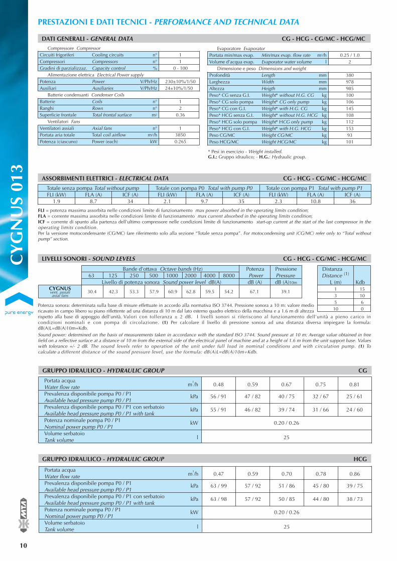
Portata acquaWater flow rate m
3/h 0.48 0.59 0.67 0.75 0.81
Prevalenza disponibile pompa P0 / P1 kPa 56 / 91 47 / 82 40 / 75 32 / 67 25 / 61Available head pressure pump P0 / P1 Prevalenza disponibile pompa P0 / P1 con serbatoio kPa 55 / 91 46 / 82 39 / 74 31 / 66 24 / 60Available head pressure pump P0 / P1 with tankPotenza nominale pompa P0 / P1 kW 0.20 / 0.26Nominal power pump P0 / P1Volume serbatoioTank volume l 25
GRUPPO IDRAULICO - HYDRAULIC GROUP CG
10
®PRESTAZIONI E DATI TECNICI - PERFORMANCE AND TECHNICAL DATA
FLI = potenza massima assorbita nelle condizioni limite di funzionamento max power absorbed in the operating limits condition; FLA = corrente massima assorbita nelle condizioni limite di funzionamento max current absorbed in the operating limits condition; ICF = corrente di spunto alla partenza dell’ultimo compressore nelle condizioni limite di funzionamento start-up current at the start of the last compressor in theoperating limits condition.Per la versione motocondensante (CG/MC) fare riferimento solo alla sezione “Totale senza pompa”. For motocondensing unit (CG/MC) refer only to “Total withoutpump” section.
Totale senza pompa Total without pump Totale con pompa P0 Total with pump P0 Totale con pompa P1 Total with pump P1FLI (kW) FLA (A) ICF (A) FLI (kW) FLA (A) ICF (A) FLI (kW) FLA (A) ICF (A)
1.9 8.7 34 2.1 9.7 35 2.3 10.8 36
ASSORBIMENTI ELETTRICI - ELECTRICAL DATA CG - HCG - CG/MC - HCG/MC
DATI GENERALI - GENERAL DATA CG - HCG - CG/MC - HCG/MC
11
0 - 100
230±10%/1/5024±10%/1/50
12
0.36
138500.265
* Pesi in esercizio - Weight installedG.I.: Gruppo idraulico; - H.S.: Hydraulic set.
Compressore CompressorCircuiti frigoriferi Cooling circuits n°Compressori Compressors n°Gradini di parzializzaz. Capacity control %
Alimentazione elettrica Electrical Power supplyPotenza Power V/Ph/HzAusiliari Auxiliaries V/Ph/Hz
Batterie condensanti Condenser CoilsBatterie Coils n°Ranghi Rows n°Superficie frontale Total frontal surface m2
Ventilatori FansVentilatori assiali Axial fans n°Portata aria totale Total coil airflow m3/hPotenza (ciascuno) Power (each) kW
GRUPPO IDRAULICO - HYDRAULIC GROUP HCG
LIVELLI SONORI - SOUND LEVELS CG - HCG - CG/MC - HCG/MC
Bande d’ottava Octave bands (Hz) Potenza Pressione63 125 250 500 1000 2000 4000 8000 Power Pressure
Livello di potenza sonora Sound power level dB(A) dB (A) dB (A)10m
30.4 42.3 53.3 57.9 60.9 62.8 59.5 54.2 67.1 39.1CYGNUSvent. assialiaxial fans
Portata acquaWater flow rate m
3/h 0.47 0.59 0.70 0.78 0.86
Prevalenza disponibile pompa P0 / P1 kPa 63 / 99 57 / 92 51 / 86 45 / 80 39 / 75Available head pressure pump P0 / P1 Prevalenza disponibile pompa P0 / P1 con serbatoio kPa 63 / 98 57 / 92 50 / 85 44 / 80 38 / 73Available head pressure pump P0 / P1 with tankPotenza nominale pompa P0 / P1 kW 0.20 / 0.26Nominal power pump P0 / P1Volume serbatoioTank volume l 25
0.25 / 1.02
Dimensione e peso Dimensions and weight38097898510010614510811215393101
Evaporatore EvaporatorPortata min/max evap. Min/max evap. flow rate m3/hVolume d’acqua evap. Evaporator water volume l
Profondità Length mmLarghezza Width mmAltezza Heigth mmPeso* CG senza G.I. Weight* without H.G. CG kgPeso* CG solo pompa Weight* CG only pump kgPeso* CG con G.I. Weight* with H.G. CG kgPeso* HCG senza G.I. Weight* without H.G. HCG kgPeso* HCG solo pompa Weight* HCG only pump kgPeso* HCG con G.I. Weight* with H.G. HCG kgPeso CG/MC Weight CG/MC kgPeso HCG/MC Weight HCG/MC kg
* Pesi in esercizio - Weight installed.G.I.: Gruppo idraulico; - H.G.: Hydraulic group.
CY
GN
US
013
Potenza sonora: determinata sulla base di misure effettuate in accordo alla normativa ISO 3744. Pressione sonora a 10 m: valore medioricavato in campo libero su piano riflettente ad una distanza di 10 m dal lato esterno quadro elettrico della macchina e a 1.6 m di altezzarispetto alla base di appoggio dell’unità. Valori con tolleranza ± 2 dB. I livelli sonori si riferiscono al funzionamento dell’unità a pieno carico incondizioni nominali e con pompa di circolazione. (1) Per calcolare il livello di pressione sonora ad una distanza diversa impiegare la formula:dB(A)L=dB(A)10m+Kdb.Sound power: determined on the basis of measurements taken in accordance with the standard ISO 3744. Sound pressure at 10 m: Average value obtained in freefield on a reflective surface at a distance of 10 m from the external side of the electrical panel of machine and at a height of 1.6 m from the unit support base. Valueswith tolerance +/- 2 dB. The sound levels refer to operation of the unit under full load in nominal conditions and with circulation pump. (1) Tocalculate a different distance of the sound pressure level, use the formula: dB(A)L=dB(A)10m+Kdb.
Distanza (1)Distance
L (m) Kdb1 153 105 610 0

CY
GN
US
013
®
11
Conditioning your ambient, maximising your comfort.
tu: temperatura acqua uscita outlet water temperature; Pf: potenza frigorifera cooling capacity; Ph: potenza termica (HCygnus) heating capacity (HCygnus);Pa: potenza assorbita dai compressori power absorbed by the compressors; Fw: portata d’acqua (∆T = 5 °C) water flow rate (∆T = 5 °C).t evap: temperatura di evaporazione (DEW) evaporating temperature (DEW); t cond: temperatura di condensazione (DEW) condensing temperature (DEW);È permessa l’interpolazione dei valori ma non la loro estrapolazione. Interpolation is allowed. Extrapolation is not permitted. Per la determinazioni di Pf, Ph, Pa e Fwper ∆T diversi da 5 °C vedere la tabella ”Coefficienti correttivi per ∆T diversi da 5 °C”. To calculate Pf, Ph, Pa and Fw for ∆T ≠ 5 °C to examine the table ”Correctionfactors for ∆T ≠ 5 °C”.
PRESTAZIONI UNITÀ SOLO FREDDO - PERFORMANCE DATA COOLING MODE
56789
10
CG
Raffreddamento Temperatura aria esterna - External air temperature ta (°C)Cooling 27 30 32 35 38 43
Pf Pa Fw Pf Pa Fw Pf Pa Fw Pf Pa Fw Pf Pa Fw Pf Pa Fwtu (°C) (kW) (kW) (m3/h) (kW) (kW) (m3/h) (kW) (kW) (m3/h) (kW) (kW) (m3/h) (kW) (kW) (m3/h) (kW) (kW) (m3/h)
4.0 1.1 0.69 3.9 1.1 0.68 3.9 1.2 0.67 3.8 1.2 0.66 3.8 1.3 0.65 3.6 1.4 0.624.1 1.1 0.71 4.1 1.1 0.70 4.0 1.2 0.69 3.9 1.2 0.68 3.9 1.3 0.67 3.7 1.4 0.644.2 1.1 0.73 4.2 1.1 0.72 4.1 1.2 0.71 4.1 1.2 0.70 4.0 1.3 0.69 3.8 1.4 0.664.4 1.1 0.75 4.3 1.2 0.74 4.3 1.2 0.73 4.2 1.2 0.72 4.1 1.3 0.71 3.9 1.4 0.684.5 1.1 0.77 4.4 1.2 0.76 4.4 1.2 0.76 4.3 1.3 0.74 4.2 1.3 0.73 4.1 1.4 0.704.6 1.1 0.80 4.6 1.2 0.79 4.5 1.2 0.78 4.4 1.3 0.77 4.4 1.3 0.75 4.2 1.4 0.72
t max.(°C)
484847474746
3035404550
HCG
Riscaldamento Temperatura aria esterna - External air temperature ta (°C)Heating -5 0 5 7 12 15
Ph Pa Fw Ph Pa Fw Ph Pa Fw Ph Pa Fw Ph Pa Fw Ph Pa Fwtu (°C) (kW) (kW) (m3/h) (kW) (kW) (m3/h) (kW) (kW) (m3/h) (kW) (kW) (m3/h) (kW) (kW) (m3/h) (kW) (kW) (m3/h)
3.6 1.0 0.62 4.0 1.0 0.69 4.4 1.0 0.77 4.6 1.0 0.80 5.2 1.1 0.90 5.6 1.1 0.973.6 1.0 0.62 4.0 1.1 0.69 4.4 1.1 0.77 4.6 1.1 0.80 5.2 1.2 0.90 5.6 1.2 0.973.6 1.1 0.62 4.0 1.2 0.69 4.4 1.2 0.76 4.6 1.2 0.80 5.2 1.2 0.90 5.6 1.3 0.973.5 1.2 0.61 3.9 1.3 0.68 4.4 1.3 0.76 4.6 1.3 0.79 5.1 1.3 0.89 5.5 1.4 0.963.5 1.4 0.60 3.8 1.4 0.67 4.3 1.4 0.75 4.5 1.4 0.78 5.1 1.4 0.88 5.5 1.5 0.95
t min.(°C)
-10-10-10-10-5
56789
10
HCG
Raffreddamento Temperatura aria esterna - External air temperature ta (°C)Cooling 27 30 32 35 38 43
Pf Pa Fw Pf Pa Fw Pf Pa Fw Pf Pa Fw Pf Pa Fw Pf Pa Fwtu (°C) (kW) (kW) (m3/h) (kW) (kW) (m3/h) (kW) (kW) (m3/h) (kW) (kW) (m3/h) (kW) (kW) (m3/h) (kW) (kW) (m3/h)
3.8 1.1 0.65 3.8 1.1 0.65 3.7 1.2 0.64 3.7 1.2 0.63 3.6 1.3 0.62 3.4 1.4 0.593.9 1.1 0.67 3.9 1.1 0.67 3.8 1.2 0.66 3.8 1.2 0.65 3.7 1.3 0.63 3.5 1.4 0.614.0 1.1 0.69 4.0 1.2 0.68 3.9 1.2 0.68 3.9 1.2 0.67 3.8 1.3 0.65 3.6 1.4 0.634.1 1.1 0.71 4.1 1.2 0.70 4.1 1.2 0.70 4.0 1.3 0.69 3.9 1.3 0.67 3.8 1.4 0.654.3 1.1 0.73 4.2 1.2 0.73 4.2 1.2 0.72 4.1 1.3 0.71 4.0 1.3 0.69 3.9 1.4 0.674.4 1.1 0.76 4.3 1.2 0.75 4.3 1.2 0.74 4.2 1.3 0.73 4.1 1.3 0.71 4.0 1.4 0.69
t max.(°C)
484747474746
03578
10
CG/MC
Raffreddamento Temperatura aria esterna - External air temperature ta (°C)Cooling 27 30 32 35 38 43
Pf Pa Pf Pa Pf Pa Pf Pa Pf Pa Pf Pat evap. (°C) (kW) (kW) (kW) (kW) (kW) (kW) (kW) (kW) (kW) (kW) (kW) (kW)
3.54 1.07 3.49 1.12 3.45 1.15 3.38 1.20 3.29 1.26 3.13 1.353.86 1.10 3.80 1.15 3.76 1.18 3.69 1.24 3.60 1.29 3.44 1.394.09 1.13 4.03 1.17 3.99 1.21 3.92 1.26 3.83 1.32 3.67 1.414.33 1.15 4.28 1.20 4.23 1.23 4.16 1.29 4.07 1.34 3.91 1.444.46 1.16 4.41 1.21 4.36 1.25 4.29 1.30 4.20 1.36 4.03 1.454.73 1.19 4.68 1.24 4.63 1.28 4.55 1.33 4.46 1.39 4.30 1.48
t max.(°C)
494848474646
03578
10
HCG/MC
Raffreddamento Temperatura aria esterna - External air temperature ta (°C)Cooling 27 30 32 35 38 43
Pf Pa Pf Pa Pf Pa Pf Pa Pf Pa Pf Pat evap. (°C) (kW) (kW) (kW) (kW) (kW) (kW) (kW) (kW) (kW) (kW) (kW) (kW)
3.46 1.06 3.41 1.11 3.37 1.14 3.30 1.19 3.22 1.25 3.06 1.343.77 1.09 3.72 1.14 3.68 1.17 3.60 1.23 3.52 1.28 3.35 1.373.99 1.11 3.94 1.16 3.90 1.20 3.82 1.25 3.74 1.31 3.57 1.404.23 1.14 4.18 1.19 4.14 1.22 4.06 1.28 3.97 1.33 3.81 1.434.36 1.15 4.30 1.20 4.26 1.24 4.18 1.29 4.10 1.34 3.93 1.444.62 1.18 4.57 1.23 4.52 1.26 4.44 1.32 4.36 1.37 4.19 1.47
t max.(°C)
484747464645
354045505560
HCG/MC
Riscaldamento Temperatura aria esterna - External air temperature ta (°C)Heating -5 0 5 7 12 15
Ph Pa Ph Pa Ph Pa Ph Pa Ph Pa Ph Pat cond. (°C) (kW) (kW) (kW) (kW) (kW) (kW) (kW) (kW) (kW) (kW) (kW) (kW)
3.91 0.88 4.29 0.93 4.75 0.96 4.94 0.97 5.53 1.00 5.93 1.023.86 0.95 4.25 1.00 4.69 1.03 4.90 1.04 5.45 1.07 5.87 1.083.78 1.04 4.16 1.08 4.60 1.11 4.79 1.12 5.36 1.15 5.77 1.173.67 1.14 4.05 1.18 4.48 1.21 4.69 1.22 5.24 1.25 5.64 1.273.55 1.25 3.92 1.28 4.37 1.31 4.56 1.32 5.13 1.35 5.51 1.37
3.79 1.39 4.23 1.42 4.41 1.43 4.99 1.46 5.35 1.48
t min.(°C)
-9-9-10-10-7-3
PRESTAZIONI UNITÀ MOTOCONDENSANTE - PERFORMANCE DATA CONDENSING UNIT
PRESTAZIONI UNITÀ MOTOCONDENSANTE REVERSIBILE - PERFORMANCE DATA REVERSIBLE CONDENSING UNIT
PRESTAZIONI POMPA DI CALORE - PERFORMANCE DATA HEAT PUMP
12
®PRESTAZIONI E DATI TECNICI - PERFORMANCE AND TECHNICAL DATA
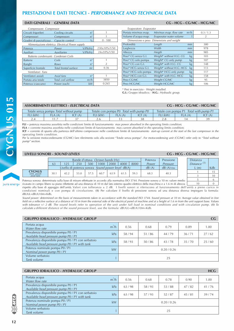
FLI = potenza massima assorbita nelle condizioni limite di funzionamento max power absorbed in the operating limits condition; FLA = corrente massima assorbita nelle condizioni limite di funzionamento max current absorbed in the operating limits condition; ICF = corrente di spunto alla partenza dell’ultimo compressore nelle condizioni limite di funzionamento start-up current at the start of the last compressor in theoperating limits condition.Per la versione motocondensante (CG/MC) fare riferimento solo alla sezione “Totale senza pompa”. For motocondensing unit (CG/MC) refer only to “Total withoutpump” section.
Totale senza pompa Total without pump Totale con pompa P0 Total with pump P0 Totale con pompa P1 Total with pump P1FLI (kW) FLA (A) ICF (A) FLI (kW) FLA (A) ICF (A) FLI (kW) FLA (A) ICF (A)
2.4 11.7 37 2.6 13 38 2.8 14 39
ASSORBIMENTI ELETTRICI - ELECTRICAL DATA CG - HCG - CG/MC - HCG/MC
DATI GENERALI GENERAL DATA CG - HCG - CG/MC - HCG/MC
11
0 - 100
230±10%/1/5024±10%/1/50
12
0.36
138500.265
Compressore CompressorCircuiti frigoriferi Cooling circuits n°Compressori Compressors n°Gradini di parzializzaz. Capacity control %
Alimentazione elettrica Electrical Power supplyPotenza Power V/Ph/HzAusiliari Auxiliaries V/Ph/Hz
Batterie condensanti Condenser CoilsBatterie Coils n°Ranghi Rows n°Superficie frontale Total frontal surface m2
Ventilatori FansVentilatori assiali Axial fans n°Portata aria totale Total coil airflow m3/hPotenza (ciascuno) Power (each) kW
Potenza sonora: determinata sulla base di misure effettuate in accordo alla normativa ISO 3744. Pressione sonora a 10 m: valore medioricavato in campo libero su piano riflettente ad una distanza di 10 m dal lato esterno quadro elettrico della macchina e a 1.6 m di altezzarispetto alla base di appoggio dell’unità. Valori con tolleranza ± 2 dB. I livelli sonori si riferiscono al funzionamento dell’unità a pieno carico incondizioni nominali e con pompa di circolazione. (1) Per calcolare il livello di pressione sonora ad una distanza diversa impiegare la formula:dB(A)L=dB(A)10m+Kdb.Sound power: determined on the basis of measurements taken in accordance with the standard ISO 3744. Sound pressure at 10 m: Average value obtained in freefield on a reflective surface at a distance of 10 m from the external side of the electrical panel of machine and at a height of 1.6 m from the unit support base. Valueswith tolerance +/- 2 dB. The sound levels refer to operation of the unit under full load in nominal conditions and with circulation pump. (1) Tocalculate a different distance of the sound pressure level, use the formula: dB(A)L=dB(A)10m+Kdb.
LIVELLI SONORI - SOUND LEVELS CG - HCG - CG/MC - HCG/MC
Bande d’ottava Octave bands (Hz) Potenza Pressione63 125 250 500 1000 2000 4000 8000 Power Pressure
Livello di potenza sonora Sound power level dB(A) dB (A) dB (A)10m
30.1 42.2 53.0 57.5 60.7 63.9 61.5 59.3 68.3 40.3CYGNUSvent. assialiaxial fans
Portata acquaWater flow rate m
3/h 0.56 0.68 0.79 0.89 1.00
Prevalenza disponibile pompa P0 / P1 kPa 58 / 94 51 / 86 44 / 79 36 / 71 27 / 62Available head pressure pump P0 / P1 Prevalenza disponibile pompa P0 / P1 con serbatoio kPa 58 / 93 50 / 86 43 / 78 35 / 70 25 / 60Available head pressure pump P0 / P1 with tankPotenza nominale pompa P0 / P1 kW 0.20 / 0.26Nominal power pump P0 / P1Volume serbatoioTank volume l 25
GRUPPO IDRAULICO - HYDRAULIC GROUP CG
GRUPPO IDRAULICO - HYDRAULIC GROUP HCG
Portata acquaWater flow rate m
3/h 0.56 0.68 0.78 0.90 1.00
Prevalenza disponibile pompa P0 / P1 kPa 63 / 98 58 / 93 53 / 88 47 / 82 41 / 76Available head pressure pump P0 / P1 Prevalenza disponibile pompa P0 / P1 con serbatoio kPa 63 / 98 57 / 93 52 / 87 45 / 81 39 / 74Available head pressure pump P0 / P1 with tankPotenza nominale pompa P0 / P1 kW 0.20 / 0.26Nominal power pump P0 / P1Volume serbatoioTank volume l 25
* Pesi in esercizio - Weight installedG.I.: Gruppo idraulico; - H.S.: Hydraulic set.
Evaporatore Evaporator0.3 / 1.3
2
38097898510310714811311715895106
Portata min/max evap. Min/max evap. flow rate m3/hVolume d’acqua evap. Evaporator water volume l
Dimensione e peso Dimensions and weightProfondità Length mmLarghezza Width mmAltezza Heigth mmPeso* CG senza G.I. Weight* without H.G. CG kgPeso* CG solo pompa Weight* CG only pump kgPeso* CG con G.I. Weight* with H.G. CG kgPeso* HCG senza G.I. Weight* without H.G. HCG kgPeso* HCG solo pompa Weight* HCG only pump kgPeso* HCG con G.I. Weight* with H.G. HCG kgPeso CG/MC Weight CG/MC kgPeso HCG/MC Weight HCG/MC kg
* Pesi in esercizio - Weight installed.G.I.: Gruppo idraulico; - H.G.: Hydraulic group.
CY
GN
US
015
Distanza (1)Distance
L (m) Kdb1 153 105 610 0

CY
GN
US
015
®
13
Conditioning your ambient, maximising your comfort.
PRESTAZIONI UNITÀ SOLO FREDDO - PERFORMANCE DATA COOLING MODE
56789
10
CG
Raffreddamento Temperatura aria esterna - External air temperature ta (°C)Cooling 27 30 32 35 38 43
Pf Pa Fw Pf Pa Fw Pf Pa Fw Pf Pa Fw Pf Pa Fw Pf Pa Fwtu (°C) (kW) (kW) (m3/h) (kW) (kW) (m3/h) (kW) (kW) (m3/h) (kW) (kW) (m3/h) (kW) (kW) (m3/h) (kW) (kW) (m3/h)
4.8 1.3 0.83 4.7 1.3 0.81 4.6 1.4 0.80 4.5 1.5 0.77 4.4 1.6 0.75 4.1 1.8 0.715.0 1.3 0.86 4.9 1.4 0.84 4.8 1.4 0.82 4.6 1.5 0.80 4.5 1.6 0.78 4.3 1.8 0.735.1 1.3 0.89 5.0 1.4 0.87 4.9 1.4 0.85 4.8 1.5 0.83 4.7 1.6 0.80 4.4 1.8 0.765.3 1.3 0.91 5.2 1.4 0.89 5.1 1.5 0.88 5.0 1.5 0.85 4.8 1.6 0.83 4.6 1.8 0.795.5 1.3 0.94 5.3 1.4 0.92 5.3 1.5 0.90 5.1 1.6 0.88 5.0 1.7 0.86 4.7 1.8 0.815.6 1.4 0.97 5.5 1.4 0.95 5.4 1.5 0.93 5.3 1.6 0.91 5.1 1.7 0.88 4.9 1.9 0.84
T max.(°C)
484747474646
3035404550
HCG
Riscaldamento Temperatura aria esterna - External air temperature ta (°C)Heating -5 0 5 7 12 15
Ph Pa Fw Ph Pa Fw Ph Pa Fw Ph Pa Fw Ph Pa Fw Ph Pa Fwtu (°C) (kW) (kW) (m3/h) (kW) (kW) (m3/h) (kW) (kW) (m3/h) (kW) (kW) (m3/h) (kW) (kW) (m3/h) (kW) (kW) (m3/h)
3.8 1.0 0.67 4.4 1.1 0.77 5.0 1.1 0.87 5.3 1.2 0.91 6.0 1.2 1.04 6.5 1.2 1.123.8 1.1 0.66 4.4 1.2 0.75 5.0 1.3 0.86 5.2 1.3 0.91 5.9 1.3 1.03 6.4 1.3 1.113.7 1.2 0.65 4.3 1.3 0.75 4.9 1.4 0.85 5.2 1.4 0.90 5.9 1.5 1.02 6.3 1.5 1.103.7 1.4 0.64 4.3 1.5 0.74 4.9 1.6 0.85 5.1 1.6 0.89 5.8 1.6 1.01 6.3 1.7 1.09
4.2 1.7 0.74 4.8 1.8 0.84 5.1 1.8 0.89 5.8 1.8 1.01 6.3 1.8 1.09
T min.(°C)
-10-10-10-9-4
56789
10
HCG
Raffreddamento Temperatura aria esterna - External air temperature ta (°C)Cooling 27 30 32 35 38 43
Pf Pa Fw Pf Pa Fw Pf Pa Fw Pf Pa Fw Pf Pa Fw Pf Pa Fwtu (°C) (kW) (kW) (m3/h) (kW) (kW) (m3/h) (kW) (kW) (m3/h) (kW) (kW) (m3/h) (kW) (kW) (m3/h) (kW) (kW) (m3/h)
4.5 1.3 0.78 4.4 1.3 0.76 4.3 1.4 0.74 4.2 1.5 0.72 4.0 1.6 0.70 3.8 1.8 0.664.7 1.3 0.80 4.5 1.4 0.78 4.4 1.4 0.77 4.3 1.5 0.74 4.2 1.6 0.72 3.9 1.8 0.684.8 1.3 0.83 4.7 1.4 0.81 4.6 1.4 0.79 4.5 1.5 0.77 4.3 1.6 0.74 4.1 1.8 0.704.9 1.3 0.85 4.8 1.4 0.83 4.7 1.5 0.82 4.6 1.6 0.79 4.5 1.7 0.77 4.2 1.8 0.735.1 1.3 0.88 5.0 1.4 0.86 4.9 1.5 0.84 4.7 1.6 0.82 4.6 1.7 0.79 4.4 1.9 0.755.2 1.4 0.90 5.1 1.4 0.88 5.0 1.5 0.87 4.9 1.6 0.84 4.8 1.7 0.82 4.5 1.9 0.78
T max.(°C)
474746464645
03578
10
CG/MC
Raffreddamento Temperatura aria esterna - External air temperature ta (°C)Cooling 27 30 32 35 38 43
Pf Pa Pf Pa Pf Pa Pf Pa Pf Pa Pf Pat evap. (°C) (kW) (kW) (kW) (kW) (kW) (kW) (kW) (kW) (kW) (kW) (kW) (kW)
4.25 1.26 4.12 1.34 4.04 1.39 3.90 1.48 3.75 1.57 3.51 1.744.67 1.32 4.54 1.39 4.45 1.45 4.31 1.54 4.17 1.63 3.92 1.804.97 1.35 4.84 1.43 4.75 1.49 4.61 1.58 4.46 1.67 4.21 1.855.28 1.38 5.15 1.46 5.06 1.52 4.92 1.61 4.78 1.71 4.52 1.895.44 1.40 5.31 1.48 5.22 1.54 5.08 1.63 4.94 1.73 4.69 1.915.78 1.43 5.65 1.51 5.56 1.57 5.42 1.67 5.27 1.77 5.02 1.95
T max.(°C)
494847464645
tu: temperatura acqua uscita outlet water temperature; Pf: potenza frigorifera cooling capacity; Ph: potenza termica (HCygnus) heating capacity (HCygnus);Pa: potenza assorbita dai compressori power absorbed by the compressors; Fw: portata d’acqua (∆T = 5 °C) water flow rate (∆T = 5 °C).t evap: temperatura di evaporazione (DEW) evaporating temperature (DEW); t cond: temperatura di condensazione (DEW) condensing temperature (DEW);È permessa l’interpolazione dei valori ma non la loro estrapolazione. Interpolation is allowed. Extrapolation is not permitted. Per la determinazioni di Pf, Ph, Pa e Fwper ∆T diversi da 5 °C vedere la tabella ”Coefficienti correttivi per ∆T diversi da 5 °C”. To calculate Pf, Ph, Pa and Fw for ∆T ≠ 5 °C to examine the table ”Correctionfactors for ∆T ≠ 5 °C”.
03578
10
HCG/MC
Raffreddamento Temperatura aria esterna - External air temperature ta (°C)Cooling 27 30 32 35 38 43
Pf Pa Pf Pa Pf Pa Pf Pa Pf Pa Pf Pat evap. (°C) (kW) (kW) (kW) (kW) (kW) (kW) (kW) (kW) (kW) (kW) (kW) (kW)
4.14 1.25 4.02 1.32 3.93 1.37 3.79 1.46 3.65 1.55 3.40 1.714.55 1.30 4.42 1.38 4.33 1.43 4.19 1.52 4.05 1.61 3.80 1.784.84 1.34 4.71 1.41 4.62 1.47 4.48 1.56 4.34 1.65 4.09 1.835.15 1.37 5.02 1.45 4.93 1.51 4.79 1.60 4.64 1.69 4.39 1.875.31 1.39 5.18 1.47 5.09 1.52 4.95 1.62 4.80 1.71 4.55 1.895.64 1.42 5.51 1.50 5.42 1.56 5.28 1.65 5.13 1.75 4.88 1.94
t max.(°C)
484746464544
354045505560
HCG/MC
Riscaldamento TTemperatura aria esterna - External air temperature ta (°C)Heating -5 0 5 7 12 15
Ph Pa Ph Pa Ph Pa Ph Pa Ph Pa Ph Pat cond. (°C) (kW) (kW) (kW) (kW) (kW) (kW) (kW) (kW) (kW) (kW) (kW) (kW)
4.07 0.84 4.72 0.96 5.39 1.04 5.68 1.06 6.43 1.11 6.96 1.133.98 0.95 4.61 1.06 5.27 1.13 5.55 1.16 6.30 1.20 6.81 1.223.88 1.10 4.50 1.20 5.14 1.27 5.40 1.29 6.15 1.33 6.64 1.353.78 1.27 4.39 1.36 5.01 1.42 5.29 1.44 6.02 1.48 6.52 1.503.71 1.46 4.31 1.54 4.91 1.60 5.18 1.62 5.91 1.65 6.39 1.67
4.23 1.74 4.84 1.80 5.10 1.81 5.81 1.85 6.30 1.86
t min.(°C)
-7-8-9-9-6-2
PRESTAZIONI POMPA DI CALORE - PERFORMANCE DATA HEAT PUMP
PRESTAZIONI UNITÀ MOTOCONDENSANTE - PERFORMANCE DATA CONDENSING UNIT
PRESTAZIONI UNITÀ MOTOCONDENSANTE REVERSIBILE - PERFORMANCE DATA REVERSIBLE CONDENSING UNIT

14
®PRESTAZIONI E DATI TECNICI - PERFORMANCE AND TECHNICAL DATA
FLI = potenza massima assorbita nelle condizioni limite di funzionamento max power absorbed in the operating limits condition; FLA = corrente massima assorbita nelle condizioni limite di funzionamento max current absorbed in the operating limits condition; ICF = corrente di spunto alla partenza dell’ultimo compressore nelle condizioni limite di funzionamento start-up current at the start of the last compressor in theoperating limits condition.Per la versione motocondensante (CG/MC) fare riferimento solo alla sezione “Totale senza pompa”. For motocondensing unit (CG/MC) refer only to “Total withoutpump” section.
Totale senza pompa Total without pump Totale con pompa P0 Total with pump P0 Totale con pompa P1 Total with pump P1FLI (kW) FLA (A) ICF (A) FLI (kW) FLA (A) ICF (A) FLI (kW) FLA (A) ICF (A)
3.2 14.5 60 3.4 15 61 3.6 17 62
ASSORBIMENTI ELETTRICI - ELECTRICAL DATA CG - HCG - CG/MC - HCG/MC
DATI GENERALI - GENERAL DATA CG - HCG - CG/MC - HCG/MC
11
0 - 100
230±10%/1/5024±10%/1/50
13
0.36
135000.265
Compressore CompressorCircuiti frigoriferi Cooling circuits n°Compressori Compressors n°Gradini di parzializzaz. Capacity control %
Alimentazione elettrica Electrical Power supplyPotenza Power V/Ph/HzAusiliari Auxiliaries V/Ph/Hz
Batterie condensanti Condenser CoilsBatterie Coils n°Ranghi Rows n°Superficie frontale Total frontal surface m2
Ventilatori FansVentilatori assiali Axial fans n°Portata aria totale Total coil airflow m3/hPotenza (ciascuno) Power (each) kW
LIVELLI SONORI - SOUND LEVELS CG - HCG - CG/MC - HCG/MC
Bande d’ottava Octave bands (Hz) Potenza Pressione63 125 250 500 1000 2000 4000 8000 Power Pressure
Livello di potenza sonora Sound power level dB(A) dB (A) dB (A)10m
29.8 41.7 52.5 58.2 60.7 65.6 60.9 60.4 69.0 41.0CYGNUSvent. assialiaxial fans
Portata acquaWater flow rate m
3/h 0.88 0.93 1.07 1.19 1.31
Prevalenza disponibile pompa P0 / P1 kPa 55 / 90 52 / 87 43 / 77 34 / 67 26 / 57Available head pressure pump P0 / P1 Prevalenza disponibile pompa P0 / P1 con serbatoio kPa 54 / 89 51 / 85 42 / 75 33 / 65 25 / 54Available head pressure pump P0 / P1 with tankPotenza nominale pompa P0 / P1 kW 0.20 / 0.26Nominal power pump P0 / P1Volume serbatoioTank volume l 25
GRUPPO IDRAULICO - HYDRAULIC GROUP CG
GRUPPO IDRAULICO - HYDRAULIC GROUP HCG
Portata acquaWater flow rate m
3/h 0.81 0.92 1.09 1.19 1.31
Prevalenza disponibile pompa P0 / P1 kPa 58 / 94 54 / 89 46 / 82 42 / 77 35 / 70Available head pressure pump P0 / P1 Prevalenza disponibile pompa P0 / P1 con serbatoio kPa 57 / 93 53 / 88 45 / 80 39 / 74 32 / 68Available head pressure pump P0 / P1 with tankPotenza nominale pompa P0 / P1 kW 0.20 / 0.26Nominal power pump P0 / P1Volume serbatoioTank volume l 25
* Pesi in esercizio - Weight installedG.I.: Gruppo idraulico; - H.S.: Hydraulic set.
Evaporatore Evaporator0.4 / 2
2Dimensione e peso Dimensions and weight
380978985113117158123127168104116
Portata min/max evap. Min/max evap. flow rate m3/hVolume d’acqua evap. Evaporator water volume l
Profondità Length mmLarghezza Width mmAltezza Heigth mmPeso* CG senza G.I. Weight* without H.G. CG kgPeso* CG solo pompa Weight* CG only pump kgPeso* CG con G.I. Weight* with H.G. CG kgPeso* HCG senza G.I. Weight* without H.G. HCG kgPeso* HCG solo pompa Weight* HCG only pump kgPeso* HCG con G.I. Weight* with H.G. HCG kgPeso CG/MC Weight CG/MC kgPeso HCG/MC Weight HCG/MC kg
* Pesi in esercizio - Weight installed.G.I.: Gruppo idraulico; - H.G.: Hydraulic group.
CY
GN
US
020
Potenza sonora: determinata sulla base di misure effettuate in accordo alla normativa ISO 3744. Pressione sonora a 10 m: valore medioricavato in campo libero su piano riflettente ad una distanza di 10 m dal lato esterno quadro elettrico della macchina e a 1.6 m di altezzarispetto alla base di appoggio dell’unità. Valori con tolleranza ± 2 dB. I livelli sonori si riferiscono al funzionamento dell’unità a pieno carico incondizioni nominali e con pompa di circolazione. (1) Per calcolare il livello di pressione sonora ad una distanza diversa impiegare la formula:dB(A)L=dB(A)10m+Kdb.Sound power: determined on the basis of measurements taken in accordance with the standard ISO 3744. Sound pressure at 10 m: Average value obtained in freefield on a reflective surface at a distance of 10 m from the external side of the electrical panel of machine and at a height of 1.6 m from the unit support base. Valueswith tolerance +/- 2 dB. The sound levels refer to operation of the unit under full load in nominal conditions and with circulation pump. (1) Tocalculate a different distance of the sound pressure level, use the formula: dB(A)L=dB(A)10m+Kdb.
Distanza (1)Distance
L (m) Kdb1 153 105 610 0

CY
GN
US
020
®
15
Conditioning your ambient, maximising your comfort.
PRESTAZIONI UNITÀ SOLO FREDDO - PERFORMANCE DATA COOLING MODE
56789
10
CG
Raffreddamento Temperatura aria esterna - External air temperature ta (°C)Cooling 27 30 32 35 38 43
Pf Pa Fw Pf Pa Fw Pf Pa Fw Pf Pa Fw Pf Pa Fw Pf Pa Fwtu (°C) (kW) (kW) (m3/h) (kW) (kW) (m3/h) (kW) (kW) (m3/h) (kW) (kW) (m3/h) (kW) (kW) (m3/h) (kW) (kW) (m3/h)
7.2 1.9 1.23 6.9 2.0 1.19 6.7 2.1 1.16 6.5 2.2 1.12 6.3 2.3 1.08 5.9 2.5 1.017.4 1.9 1.27 7.1 2.0 1.23 7.0 2.1 1.20 6.7 2.2 1.15 6.5 2.3 1.11 6.1 2.5 1.047.6 1.9 1.31 7.3 2.1 1.26 7.2 2.1 1.23 6.9 2.3 1.19 6.7 2.4 1.15 6.3 2.6 1.087.8 2.0 1.35 7.6 2.1 1.30 7.4 2.2 1.27 7.1 2.3 1.23 6.9 2.4 1.19 6.5 2.6 1.128.0 2.0 1.38 7.8 2.1 1.34 7.6 2.2 1.31 7.4 2.3 1.27 7.1 2.4 1.23 6.7 2.6 1.168.3 2.0 1.42 8.0 2.1 1.38 7.8 2.2 1.35 7.6 2.3 1.31 7.4 2.5 1.27 7.0 2.7 1.20
t max.(°C)
474746464545
56789
10
HCG
Raffreddamento Temperatura aria esterna - External air temperature ta (°C)Cooling 27 30 32 35 38 43
Pf Pa Fw Pf Pa Fw Pf Pa Fw Pf Pa Fw Pf Pa Fw Pf Pa Fwtu (°C) (kW) (kW) (m3/h) (kW) (kW) (m3/h) (kW) (kW) (m3/h) (kW) (kW) (m3/h) (kW) (kW) (m3/h) (kW) (kW) (m3/h)
6.8 1.9 1.16 6.5 2.0 1.12 6.4 2.1 1.09 6.1 2.2 1.05 5.9 2.3 1.01 5.5 2.5 0.957.0 1.9 1.20 6.7 2.0 1.16 6.6 2.1 1.13 6.3 2.2 1.09 6.1 2.4 1.05 5.7 2.6 0.987.2 1.9 1.23 6.9 2.1 1.19 6.8 2.1 1.16 6.5 2.3 1.12 6.3 2.4 1.08 5.9 2.6 1.027.4 2.0 1.27 7.1 2.1 1.23 7.0 2.2 1.20 6.7 2.3 1.16 6.5 2.4 1.12 6.1 2.6 1.057.6 2.0 1.31 7.3 2.1 1.26 7.2 2.2 1.24 6.9 2.3 1.20 6.7 2.4 1.16 6.3 2.6 1.097.8 2.0 1.34 7.5 2.1 1.30 7.4 2.2 1.27 7.2 2.3 1.23 6.9 2.5 1.19 6.5 2.7 1.13
t max.(°C)
474646454645
03578
10
CG/MC
Raffreddamento Temperatura aria esterna - External air temperature ta (°C)Cooling 27 30 32 35 38 43
Pf Pa Pf Pa Pf Pa Pf Pa Pf Pa Pf Pat evap. (°C) (kW) (kW) (kW) (kW) (kW) (kW) (kW) (kW) (kW) (kW) (kW) (kW)
6.37 1.89 6.10 2.00 5.92 2.07 5.67 2.19 5.42 2.31 5.01 2.516.99 1.97 6.72 2.08 6.55 2.16 6.29 2.27 6.05 2.39 5.63 2.597.42 2.02 7.15 2.13 6.98 2.21 6.73 2.33 6.48 2.45 6.07 2.657.87 2.07 7.60 2.19 7.43 2.26 7.18 2.38 6.93 2.50 6.52 2.708.10 2.10 7.83 2.21 7.66 2.29 7.41 2.41 7.17 2.53 6.75 2.738.57 2.15 8.31 2.26 8.14 2.34 7.89 2.46 7.64 2.58 7.23 2.78
3035404550
HCG
Riscaldamento Temperatura aria esterna - External air temperature ta (°C)Heating -5 0 5 7 12 15
Ph Pa Fw Ph Pa Fw Ph Pa Fw Ph Pa Fw Ph Pa Fw Ph Pa Fwtu (°C) (kW) (kW) (m3/h) (kW) (kW) (m3/h) (kW) (kW) (m3/h) (kW) (kW) (m3/h) (kW) (kW) (m3/h) (kW) (kW) (m3/h)
5.5 1.4 0.96 6.4 1.5 1.11 7.3 1.6 1.27 7.7 1.6 1.33 8.6 1.7 1.49 9.2 1.7 1.605.3 1.6 0.92 6.2 1.7 1.07 7.1 1.8 1.23 7.5 1.8 1.30 8.4 1.9 1.46 9.0 1.9 1.575.2 1.8 0.90 6.0 1.9 1.05 7.0 2.0 1.21 7.3 2.0 1.27 8.3 2.1 1.44 8.9 2.1 1.545.1 2.1 0.88 5.9 2.2 1.03 6.8 2.2 1.18 7.2 2.3 1.25 8.1 2.3 1.42 8.7 2.3 1.52
5.8 2.4 1.02 6.7 2.5 1.17 7.1 2.5 1.23 8.0 2.5 1.39 8.6 2.6 1.51
t min.(°C)
-9-9-10-7-2
t max.(°C)
494646454543
tu: temperatura acqua uscita outlet water temperature; Pf: potenza frigorifera cooling capacity; Ph: potenza termica (HCygnus) heating capacity (HCygnus);Pa: potenza assorbita dai compressori power absorbed by the compressors; Fw: portata d’acqua (∆T = 5 °C) water flow rate (∆T = 5 °C).t evap: temperatura di evaporazione (DEW) evaporating temperature (DEW); t cond: temperatura di condensazione (DEW) condensing temperature (DEW);È permessa l’interpolazione dei valori ma non la loro estrapolazione. Interpolation is allowed. Extrapolation is not permitted. Per la determinazioni di Pf, Ph, Pa e Fwper ∆T diversi da 5 °C vedere la tabella ”Coefficienti correttivi per ∆T diversi da 5 °C”. To calculate Pf, Ph, Pa and Fw for ∆T ≠ 5 °C to examine the table ”Correctionfactors for ∆T ≠ 5 °C”.
03578
10
HCG/MC
Raffreddamento Temperatura aria esterna - External air temperature ta (°C)Cooling 27 30 32 35 38 43
Pf Pa Pf Pa Pf Pa Pf Pa Pf Pa Pf Pat evap. (°C) (kW) (kW) (kW) (kW) (kW) (kW) (kW) (kW) (kW) (kW) (kW) (kW)
6.21 1.86 5.93 1.97 5.76 2.05 5.50 2.16 5.25 2.28 4.84 2.486.82 1.94 6.55 2.06 6.37 2.13 6.12 2.25 5.87 2.37 5.45 2.577.24 2.00 6.97 2.11 6.80 2.19 6.55 2.30 6.30 2.42 5.88 2.627.69 2.05 7.42 2.16 7.24 2.24 6.99 2.36 6.74 2.48 6.33 2.687.91 2.08 7.65 2.19 7.47 2.27 7.22 2.39 6.97 2.50 6.56 2.708.38 2.13 8.11 2.24 7.94 2.32 7.69 2.44 7.44 2.56 7.03 2.76
t max.(°C)
504847464645
354045505560
HCG/MC
Riscaldamento Temperatura aria esterna - External air temperature ta (°C)Heating -5 0 5 7 12 15
Ph Pa Ph Pa Ph Pa Ph Pa Ph Pa Ph Pat cond. (°C) (kW) (kW) (kW) (kW) (kW) (kW) (kW) (kW) (kW) (kW) (kW) (kW)
6.45 1.31 7.54 1.42 7.99 1.45 9.14 1.52 9.89 1.555.25 1.35 6.28 1.50 7.32 1.59 7.74 1.62 8.87 1.68 9.61 1.715.14 1.60 6.12 1.72 7.10 1.81 7.52 1.83 8.63 1.89 9.33 1.915.02 1.86 5.98 1.96 6.93 2.03 7.33 2.06 8.42 2.10 9.10 2.134.93 2.11 5.84 2.20 6.77 2.27 7.17 2.29 8.20 2.33 8.90 2.36
5.70 2.45 6.60 2.50 6.97 2.52 8.02 2.57 8.70 2.59
t min.(°C)
-5-7-9-10-6-2
PRESTAZIONI POMPA DI CALORE - PERFORMANCE DATA HEAT PUMP
PRESTAZIONI UNITÀ MOTOCONDENSANTE - PERFORMANCE DATA CONDENSING UNIT
PRESTAZIONI UNITÀ MOTOCONDENSANTE REVERSIBILE - PERFORMANCE DATA REVERSIBLE CONDENSING UNIT

16
®PRESTAZIONI E DATI TECNICI - PERFORMANCE AND TECHNICAL DATA
FLI = potenza massima assorbita nelle condizioni limite di funzionamento max power absorbed in the operating limits condition; FLA = corrente massima assorbita nelle condizioni limite di funzionamento max current absorbed in the operating limits condition; ICF = corrente di spunto alla partenza dell’ultimo compressore nelle condizioni limite di funzionamento start-up current at the start of the last compressor in theoperating limits condition.Per la versione motocondensante (CG/MC) fare riferimento solo alla sezione “Totale senza pompa”. For motocondensing unit (CG/MC) refer only to “Total withoutpump” section.
Totale senza pompa Total without pump Totale con pompa P0 Total with pump P0 Totale con pompa P1 Total with pump P1FLI (kW) FLA (A) ICF (A) FLI (kW) FLA (A) ICF (A) FLI (kW) FLA (A) ICF (A)
4.8 9 36 - - - 5.4 11 37
ASSORBIMENTI ELETTRICI - ELECTRICAL DATA CG - HCG - CG/MC - HCG/MC
DATI GENERALI - GENERAL DATA CG - HCG - CG/MC - HCG/MC
11
0 - 100
400±10%/3N/5024±10%/1/50
12
0.78
279000.265
Compressore CompressorCircuiti frigoriferi Cooling circuits n°Compressori Compressors n°Gradini di parzializzaz. Capacity control %
Alimentazione elettrica Electrical Power supplyPotenza Power V/Ph/HzAusiliari Auxiliaries V/Ph/Hz
Batterie condensanti Condenser CoilsBatterie Coils n°Ranghi Rows n°Superficie frontale Total frontal surface m2
Ventilatori FansVentilatori assiali Axial fans n°Portata aria totale Total coil airflow m3/hPotenza (ciascuno) Power (each) kW
LIVELLI SONORI - SOUND LEVELS CG - HCG - CG/MC - HCG/MC
Bande d’ottava Octave bands (Hz) Potenza Pressione63 125 250 500 1000 2000 4000 8000 Power Pressure
Livello di potenza sonora Sound power level dB(A) dB (A) dB (A)10m
35.9 45.9 57.3 62.7 66.0 66.8 62.3 56.6 71.3 43.3CYGNUSvent. assialiaxial fans
Portata acquaWater flow rate m
3/h 1.29 1.42 1.61 1.84 2.14
Prevalenza disponibile pompa P1 kPa 166 157 144 125 98Available head pressure pump P1 Prevalenza disponibile pompa P1 con serbatoio kPa 164 154 140 120 91Available head pressure pump P1 with tankPotenza nominale pompa P1 kW 0.37Nominal power pump P1Volume serbatoioTank volume l 70
GRUPPO IDRAULICO - HYDRAULIC GROUP CG
GRUPPO IDRAULICO - HYDRAULIC GROUP HCG
Portata acquaWater flow rate m
3/h 1.29 1.46 1.62 1.96 2.10
Prevalenza disponibile pompa P1 kPa 181 173 165 147 138Available head pressure pump P1 Prevalenza disponibile pompa P1 con serbatoio kPa 178 170 161 141 131Available head pressure pump P1 with tankPotenza nominale pompa P1 kW 0.37Nominal power pump P1Volume serbatoioTank volume l 70
* Pesi in esercizio - Weight installedG.I.: Gruppo idraulico; - H.S.: Hydraulic set.
Evaporatore Evaporator0.55 / 2.65
3
55014201288158163290170182302147157
Portata min/max evap. Min/max evap. flow rate m3/hVolume d’acqua evap. Evaporator water volume l
Dimensione e peso Dimensions and weightProfondità Length mmLarghezza Width mmAltezza Heigth mmPeso* CG senza G.I. Weight* without H.G. CG kgPeso* CG solo pompa Weight* CG only pump kgPeso* CG con G.I. Weight* with H.G. CG kgPeso* HCG senza G.I. Weight* without H.G. HCG kgPeso* HCG solo pompa Weight* HCG only pump kgPeso* HCG con G.I. Weight* with H.G. HCG kgPeso CG/MC Weight CG/MC kgPeso HCG/MC Weight HCG/MC kg
* Pesi in esercizio - Weight installed.G.I.: Gruppo idraulico; - H.G.: Hydraulic group.
CY
GN
US
031
Potenza sonora: determinata sulla base di misure effettuate in accordo alla normativa ISO 3744. Pressione sonora a 10 m: valore medioricavato in campo libero su piano riflettente ad una distanza di 10 m dal lato esterno quadro elettrico della macchina e a 1.6 m di altezzarispetto alla base di appoggio dell’unità. Valori con tolleranza ± 2 dB. I livelli sonori si riferiscono al funzionamento dell’unità a pieno carico incondizioni nominali e con pompa di circolazione. (1) Per calcolare il livello di pressione sonora ad una distanza diversa impiegare la formula:dB(A)L=dB(A)10m+Kdb.Sound power: determined on the basis of measurements taken in accordance with the standard ISO 3744. Sound pressure at 10 m: Average value obtained in freefield on a reflective surface at a distance of 10 m from the external side of the electrical panel of machine and at a height of 1.6 m from the unit support base. Valueswith tolerance +/- 2 dB. The sound levels refer to operation of the unit under full load in nominal conditions and with circulation pump. (1) Tocalculate a different distance of the sound pressure level, use the formula: dB(A)L=dB(A)10m+Kdb.
Distanza (1)Distance
L (m) Kdb1 153 105 610 0

CY
GN
US
031
®
17
Conditioning your ambient, maximising your comfort.
PRESTAZIONI UNITÀ SOLO FREDDO - PERFORMANCE DATA COOLING MODE
56789
10
CG
Raffreddamento Temperatura aria esterna - External air temperature ta (°C)Cooling 27 30 32 35 38 43
Pf Pa Fw Pf Pa Fw Pf Pa Fw Pf Pa Fw Pf Pa Fw Pf Pa Fwtu (°C) (kW) (kW) (m3/h) (kW) (kW) (m3/h) (kW) (kW) (m3/h) (kW) (kW) (m3/h) (kW) (kW) (m3/h) (kW) (kW) (m3/h)
10.0 2.6 1.7 9.7 2.8 1.7 9.5 2.9 1.6 9.2 3.1 1.6 8.9 3.3 1.5 8.4 3.6 1.410.2 2.7 1.8 10.0 2.8 1.7 9.8 2.9 1.7 9.5 3.1 1.6 9.2 3.3 1.6 8.6 3.7 1.510.5 2.7 1.8 10.2 2.9 1.8 10.0 3.0 1.7 9.7 3.2 1.7 9.4 3.4 1.6 8.9 3.7 1.510.8 2.7 1.9 10.5 2.9 1.8 10.3 3.0 1.8 10.0 3.2 1.7 9.7 3.4 1.7 9.2 3.7 1.611.1 2.7 1.9 10.8 2.9 1.9 10.6 3.0 1.8 10.3 3.2 1.8 10.0 3.4 1.7 9.4 3.8 1.611.3 2.8 2.0 11.1 2.9 1.9 10.9 3.1 1.9 10.6 3.2 1.8 10.2 3.4 1.8 9.7 3.8 1.7
t max.(°C)
474747464646
3035404550
HCG
Riscaldamento Temperatura aria esterna - External air temperature ta (°C)Heating -5 0 5 7 12 15
Ph Pa Fw Ph Pa Fw Ph Pa Fw Ph Pa Fw Ph Pa Fw Ph Pa Fwtu (°C) (kW) (kW) (m3/h) (kW) (kW) (m3/h) (kW) (kW) (m3/h) (kW) (kW) (m3/h) (kW) (kW) (m3/h) (kW) (kW) (m3/h)
8.5 2.3 1.5 9.7 2.3 1.7 10.7 2.3 1.9 11.4 2.3 2.0 12.6 2.3 2.2 13.4 2.4 2.38.4 2.5 1.4 9.5 2.6 1.7 10.5 2.6 1.8 11.2 2.6 1.9 12.5 2.6 2.2 13.3 2.6 2.38.2 2.9 1.4 9.4 2.9 1.6 10.6 2.9 1.8 11.1 2.9 1.9 12.3 2.9 2.1 13.1 2.9 2.38.1 3.2 1.4 9.3 3.2 1.6 10.4 3.2 1.8 10.9 3.2 1.9 12.2 3.3 2.1 13.0 3.3 2.38.0 3.6 1.4 9.1 3.6 1.6 10.3 3.6 1.8 10.8 3.6 1.9 12.1 3.6 2.1 12.9 3.7 2.2
t min.(°C)
-10-10-10-9-5
56789
10
HCG
Raffreddamento Temperatura aria esterna - External air temperature ta (°C)Cooling 27 30 32 35 38 43
Pf Pa Fw Pf Pa Fw Pf Pa Fw Pf Pa Fw Pf Pa Fw Pf Pa Fwtu (°C) (kW) (kW) (m3/h) (kW) (kW) (m3/h) (kW) (kW) (m3/h) (kW) (kW) (m3/h) (kW) (kW) (m3/h) (kW) (kW) (m3/h)
9.5 2.7 1.6 9.3 2.8 1.6 9.1 2.9 1.6 8.8 3.1 1.5 8.5 3.3 1.5 8.0 3.7 1.49.8 2.7 1.7 9.5 2.8 1.6 9.3 3.0 1.6 9.0 3.2 1.6 8.7 3.3 1.5 8.2 3.7 1.410.0 2.7 1.7 9.8 2.9 1.7 9.6 3.0 1.7 9.3 3.2 1.6 9.0 3.4 1.6 8.5 3.7 1.510.3 2.7 1.8 10.0 2.9 1.7 9.9 3.0 1.7 9.6 3.2 1.6 9.3 3.4 1.6 8.7 3.8 1.510.6 2.8 1.8 10.3 2.9 1.8 10.1 3.0 1.7 9.8 3.2 1.7 9.5 3.4 1.6 9.0 3.8 1.610.8 2.8 1.9 10.6 3.0 1.8 10.4 3.1 1.8 10.1 3.3 1.7 9.8 3.5 1.7 9.3 3.8 1.6
t max.(°C)
484847474746
03578
10
CG/MC
Raffreddamento Temperatura aria esterna - External air temperature ta (°C)Cooling 27 30 32 35 38 43
Pf Pa Pf Pa Pf Pa Pf Pa Pf Pa Pf Pat evap. (°C) (kW) (kW) (kW) (kW) (kW) (kW) (kW) (kW) (kW) (kW) (kW) (kW)
8.99 2.64 8.71 2.81 8.51 2.92 8.21 3.11 7.89 3.30 7.34 3.649.79 2.72 9.51 2.89 9.31 3.01 9.00 3.19 8.68 3.39 8.13 3.7410.34 2.77 10.05 2.95 9.85 3.07 9.54 3.25 9.22 3.45 8.66 3.8010.90 2.83 10.61 3.00 10.41 3.13 10.10 3.32 9.78 3.52 9.21 3.8711.18 2.86 10.89 3.03 10.69 3.16 10.38 3.35 10.06 3.55 9.49 3.9111.76 2.92 11.47 3.09 11.26 3.22 10.95 3.41 10.63 3.62 10.06 3.98
t max.(°C)
484747464545
tu: temperatura acqua uscita outlet water temperature; Pf: potenza frigorifera cooling capacity; Ph: potenza termica (HCygnus) heating capacity (HCygnus);Pa: potenza assorbita dai compressori power absorbed by the compressors; Fw: portata d’acqua (∆T = 5 °C) water flow rate (∆T = 5 °C).t evap: temperatura di evaporazione (DEW) evaporating temperature (DEW); t cond: temperatura di condensazione (DEW) condensing temperature (DEW);È permessa l’interpolazione dei valori ma non la loro estrapolazione. Interpolation is allowed. Extrapolation is not permitted. Per la determinazioni di Pf, Ph, Pa e Fwper ∆T diversi da 5 °C vedere la tabella ”Coefficienti correttivi per ∆T diversi da 5 °C”. To calculate Pf, Ph, Pa and Fw for ∆T ≠ 5 °C to examine the table ”Correctionfactors for ∆T ≠ 5 °C”.
03578
10
HCG/MC
Raffreddamento Temperatura aria esterna - External air temperature ta (°C)Cooling 27 30 32 35 38 43
Pf Pa Pf Pa Pf Pa Pf Pa Pf Pa Pf Pat evap. (°C) (kW) (kW) (kW) (kW) (kW) (kW) (kW) (kW) (kW) (kW) (kW) (kW)
8.73 2.62 8.45 2.78 8.25 2.90 7.95 3.08 7.63 3.27 7.08 3.619.53 2.69 9.24 2.86 9.04 2.98 8.74 3.16 8.42 3.36 7.86 3.7010.07 2.75 9.78 2.92 9.58 3.04 9.28 3.22 8.96 3.42 8.40 3.7710.62 2.80 10.33 2.98 10.13 3.10 9.82 3.29 9.50 3.48 8.94 3.8410.90 2.83 10.61 3.00 10.41 3.13 10.10 3.32 9.78 3.52 9.22 3.8711.47 2.89 11.18 3.06 10.98 3.19 10.67 3.38 10.34 3.58 9.78 3.94
t max.(°C)
494847464645
354045505560
HCG/MC
Riscaldamento Temperatura aria esterna - External air temperature ta (°C)Heating -5 0 5 7 12 15
Ph Pa Ph Pa Ph Pa Ph Pa Ph Pa Ph Pat cond. (°C) (kW) (kW) (kW) (kW) (kW) (kW) (kW) (kW) (kW) (kW) (kW) (kW)
8.35 2.17 9.73 2.18 11.14 2.20 11.73 2.21 13.28 2.24 14.27 2.268.23 2.39 9.59 2.41 10.94 2.43 11.55 2.44 13.03 2.47 14.00 2.488.08 2.68 9.40 2.70 10.72 2.72 11.29 2.73 12.78 2.76 13.74 2.787.93 3.01 9.22 3.02 10.51 3.05 11.05 3.06 12.51 3.08 13.45 3.107.76 3.36 9.02 3.38 10.31 3.40 10.83 3.41 12.24 3.44 13.18 3.46
8.87 3.77 10.09 3.80 10.62 3.81 11.99 3.84 12.88 3.85
t min.(°C)
-8-9-10-11-7-2
PRESTAZIONI POMPA DI CALORE - PERFORMANCE DATA HEAT PUMP
PRESTAZIONI UNITÀ MOTOCONDENSANTE - PERFORMANCE DATA CONDENSING UNIT
PRESTAZIONI UNITÀ MOTOCONDENSANTE REVERSIBILE - PERFORMANCE DATA REVERSIBLE CONDENSING UNIT

Potenza sonora: determinata sulla base di misure effettuate in accordo alla normativa ISO 3744. Pressione sonora a 10 m: valore medioricavato in campo libero su piano riflettente ad una distanza di 10 m dal lato esterno quadro elettrico della macchina e a 1.6 m di altezzarispetto alla base di appoggio dell’unità. Valori con tolleranza ± 2 dB. I livelli sonori si riferiscono al funzionamento dell’unità a pieno carico incondizioni nominali e con pompa di circolazione. (1) Per calcolare il livello di pressione sonora ad una distanza diversa impiegare la formula:dB(A)L=dB(A)10m+Kdb.Sound power: determined on the basis of measurements taken in accordance with the standard ISO 3744. Sound pressure at 10 m: Average value obtained in freefield on a reflective surface at a distance of 10 m from the external side of the electrical panel of machine and at a height of 1.6 m from the unit support base. Valueswith tolerance +/- 2 dB. The sound levels refer to operation of the unit under full load in nominal conditions and with circulation pump. (1) Tocalculate a different distance of the sound pressure level, use the formula: dB(A)L=dB(A)10m+Kdb.
18
®PRESTAZIONI E DATI TECNICI - PERFORMANCE AND TECHNICAL DATA
FLI = potenza massima assorbita nelle condizioni limite di funzionamento max power absorbed in the operating limits condition; FLA = corrente massima assorbita nelle condizioni limite di funzionamento max current absorbed in the operating limits condition; ICF = corrente di spunto alla partenza dell’ultimo compressore nelle condizioni limite di funzionamento start-up current at the start of the last compressor in theoperating limits condition.Per la versione motocondensante (CG/MC) fare riferimento solo alla sezione “Totale senza pompa”. For motocondensing unit (CG/MC) refer only to “Total withoutpump” section.
Totale senza pompa Total without pump Totale con pompa P0 Total with pump P0 Totale con pompa P1 Total with pump P1FLI (kW) FLA (A) ICF (A) FLI (kW) FLA (A) ICF (A) FLI (kW) FLA (A) ICF (A)
6.2 12 57 - - - 7 14 58
ASSORBIMENTI ELETTRICI - ELECTRICAL DATA CG - HCG - CG/MC - HCG/MC
DATI GENERALI - GENERAL DATA CG - HCG - CG/MC - HCG/MC
11
0 - 100
400±10%/3N/5024±10%/3/50
13
0.78
273000.265
Compressore CompressorCircuiti frigoriferi Cooling circuits n°Compressori Compressors n°Gradini di parzializzaz. Capacity control %
Alimentazione elettrica Electrical Power supplyPotenza Power V/Ph/HzAusiliari Auxiliaries V/Ph/Hz
Batterie condensanti Condenser CoilsBatterie Coils n°Ranghi Rows n°Superficie frontale Total frontal surface m2
Ventilatori FansVentilatori assiali Axial fans n°Portata aria totale Total coil airflow m3/hPotenza (ciascuno) Power (each) kW
LIVELLI SONORI - SOUND LEVELS CG - HCG - CG/MC - HCG/MC
Bande d’ottava Octave bands (Hz) Potenza Pressione63 125 250 500 1000 2000 4000 8000 Power Pressure
Livello di potenza sonora Sound power level dB(A) dB (A) dB (A)10m
35.0 42.4 53.4 66.0 67.2 68.8 62.0 57.8 72.8 44.8CYGNUSvent. assialiaxial fans
Portata acquaWater flow rate m
3/h 1.62 2.00 2.33 2.62 3.00
Prevalenza disponibile pompa P1 kPa 165 143 121 100 69Available head pressure pump P1 Prevalenza disponibile pompa P1 con serbatoio kPa 160 137 113 89 55Available head pressure pump P1 with tankPotenza nominale pompa P1 kW 0.37Nominal power pump P1Volume serbatoioTank volume l 70
GRUPPO IDRAULICO - HYDRAULIC GROUP CG
GRUPPO IDRAULICO - HYDRAULIC GROUP HCG
Portata acquaWater flow rate m
3/h 1.64 2.04 2.33 2.71 3.01
Prevalenza disponibile pompa P1 kPa 173 155 140 117 97Available head pressure pump P1 Prevalenza disponibile pompa P1 con serbatoio kPa 169 148 131 106 83Available head pressure pump P1 with tankPotenza nominale pompa P1 kW 0.37Nominal power pump P1Volume serbatoioTank volume l 70
* Pesi in esercizio - Weight installedG.I.: Gruppo idraulico; - H.S.: Hydraulic set.
Evaporatore Evaporator0.8 / 3.75
3Dimensione e peso Dimensions and weight
55014201288189194321199213331173185
Portata min/max evap. Min/max evap. flow rate m3/hVolume d’acqua evap. Evaporator water volume l
Profondità Length mmLarghezza Width mmAltezza Heigth mmPeso* CG senza G.I. Weight* without H.G. CG kgPeso* CG solo pompa Weight* CG only pump kgPeso* CG con G.I. Weight* with H.G. CG kgPeso* HCG senza G.I. Weight* without H.G. HCG kgPeso* HCG solo pompa Weight* HCG only pump kgPeso* HCG con G.I. Weight* with H.G. HCG kgPeso CG/MC Weight CG/MC kgPeso HCG/MC Weight HCG/MC kg
* Pesi in esercizio - Weight installed.G.I.: Gruppo idraulico; - H.G.: Hydraulic group.
CY
GN
US
051
Distanza (1)Distance
L (m) Kdb1 153 105 610 0

CY
GN
US
051
®
19
Conditioning your ambient, maximising your comfort.
PRESTAZIONI UNITÀ SOLO FREDDO - PERFORMANCE DATA COOLING MODE
56789
10
CG
Raffreddamento Temperatura aria esterna - External air temperature ta (°C)Cooling 27 30 32 35 38 43
Pf Pa Fw Pf Pa Fw Pf Pa Fw Pf Pa Fw Pf Pa Fw Pf Pa Fwtu (°C) (kW) (kW) (m3/h) (kW) (kW) (m3/h) (kW) (kW) (m3/h) (kW) (kW) (m3/h) (kW) (kW) (m3/h) (kW) (kW) (m3/h)
13.5 3.5 2.3 13.1 3.7 2.3 12.9 3.8 2.2 12.6 4.1 2.2 12.3 4.4 2.1 11.8 4.9 2.014.0 3.5 2.4 13.6 3.7 2.3 13.4 3.9 2.3 13.0 4.1 2.2 12.7 4.4 2.2 12.3 4.9 2.114.4 3.5 2.5 14.1 3.8 2.4 13.8 3.9 2.4 13.5 4.2 2.3 13.2 4.5 2.3 12.8 5.0 2.214.9 3.6 2.6 14.6 3.8 2.5 14.3 4.0 2.5 14.0 4.2 2.4 13.7 4.5 2.4 13.3 5.0 2.315.4 3.6 2.7 15.1 3.8 2.6 14.8 4.0 2.6 14.5 4.3 2.5 14.2 4.6 2.5 13.8 5.1 2.416.0 3.6 2.7 15.6 3.9 2.7 15.4 4.0 2.6 15.0 4.3 2.6 14.8 4.6 2.5 14.4 5.2 2.5
t max.(°C)
464646454544
3035404550
HCG
Riscaldamento Temperatura aria esterna - External air temperature ta (°C)Heating -5 0 5 7 12 15
Ph Pa Fw Ph Pa Fw Ph Pa Fw Ph Pa Fw Ph Pa Fw Ph Pa Fwtu (°C) (kW) (kW) (m3/h) (kW) (kW) (m3/h) (kW) (kW) (m3/h) (kW) (kW) (m3/h) (kW) (kW) (m3/h) (kW) (kW) (m3/h)
11.7 2.8 2.0 12.8 2.9 2.2 14.2 3.0 2.5 14.9 3.0 2.6 16.8 3.1 2.9 18.1 3.1 3.111.3 3.2 2.0 12.5 3.3 2.2 13.9 3.3 2.4 14.6 3.4 2.5 16.6 3.4 2.9 17.9 3.5 3.111.2 3.6 1.9 12.3 3.7 2.1 13.8 3.7 2.4 14.5 3.8 2.5 16.4 3.8 2.8 17.7 3.9 3.111.1 4.0 1.9 12.3 4.1 2.1 13.8 4.2 2.4 14.5 4.2 2.5 16.4 4.3 2.9 17.8 4.3 3.1
12.4 4.6 2.2 13.9 4.7 2.4 14.6 4.7 2.5 16.5 4.8 2.9 17.9 4.8 3.1
t min.(°C)
-9-9-10-8-3
56789
10
HCG
Raffreddamento Temperatura aria esterna - External air temperature ta (°C)Cooling 27 30 32 35 38 43
Pf Pa Fw Pf Pa Fw Pf Pa Fw Pf Pa Fw Pf Pa Fw Pf Pa Fwtu (°C) (kW) (kW) (m3/h) (kW) (kW) (m3/h) (kW) (kW) (m3/h) (kW) (kW) (m3/h) (kW) (kW) (m3/h) (kW) (kW) (m3/h)
12.8 3.5 2.2 12.4 3.7 2.1 12.2 3.8 2.1 11.9 4.1 2.0 11.6 4.4 2.0 11.1 4.9 1.913.2 3.5 2.3 12.8 3.7 2.2 12.6 3.9 2.2 12.3 4.1 2.1 12.0 4.4 2.1 11.6 4.9 2.013.7 3.5 2.4 13.3 3.7 2.3 13.1 3.9 2.2 12.7 4.2 2.2 12.4 4.4 2.1 12.0 5.0 2.114.1 3.6 2.4 13.7 3.8 2.4 13.5 3.9 2.3 13.2 4.2 2.3 12.9 4.5 2.2 12.5 5.0 2.214.6 3.6 2.5 14.2 3.8 2.4 14.0 4.0 2.4 13.7 4.3 2.4 13.4 4.5 2.3 13.0 5.1 2.215.1 3.6 2.6 14.7 3.9 2.5 14.5 4.0 2.5 14.2 4.3 2.4 13.9 4.6 2.4 13.5 5.1 2.3
t max.(°C)
464646454544
03578
10
CG/MC
Raffreddamento Temperatura aria esterna - External air temperature ta (°C)Cooling 27 30 32 35 38 43
Pf Pa Pf Pa Pf Pa Pf Pa Pf Pa Pf Pat evap. (°C) (kW) (kW) (kW) (kW) (kW) (kW) (kW) (kW) (kW) (kW) (kW) (kW)
12.01 3.46 11.60 3.67 11.35 3.83 11.00 4.08 10.67 4.35 10.21 4.8613.25 3.58 12.85 3.80 12.60 3.96 12.25 4.22 11.94 4.50 11.49 5.0314.17 3.66 13.78 3.89 13.53 4.05 13.19 4.32 12.88 4.61 12.44 5.1515.16 3.74 14.78 3.98 14.54 4.15 14.20 4.43 13.90 4.72 13.47 5.2815.69 3.79 15.31 4.03 15.07 4.20 14.74 4.48 14.44 4.78 14.02 5.3516.80 3.88 16.43 4.13 16.20 4.31 15.87 4.60 15.58 4.91 15.17 5.49
t max.(°C)
494746454544
tu: temperatura acqua uscita outlet water temperature; Pf: potenza frigorifera cooling capacity; Ph: potenza termica (HCygnus) heating capacity (HCygnus);Pa: potenza assorbita dai compressori power absorbed by the compressors; Fw: portata d’acqua (∆T = 5 °C) water flow rate (∆T = 5 °C).t evap: temperatura di evaporazione (DEW) evaporating temperature (DEW); t cond: temperatura di condensazione (DEW) condensing temperature (DEW);È permessa l’interpolazione dei valori ma non la loro estrapolazione. Interpolation is allowed. Extrapolation is not permitted. Per la determinazioni di Pf, Ph, Pa e Fwper ∆T diversi da 5 °C vedere la tabella ”Coefficienti correttivi per ∆T diversi da 5 °C”. To calculate Pf, Ph, Pa and Fw for ∆T ≠ 5 °C to examine the table ”Correctionfactors for ∆T ≠ 5 °C”.
03578
10
HCG/MC
Raffreddamento Temperatura aria esterna - External air temperature ta (°C)Cooling 27 30 32 35 38 43
Pf Pa Pf Pa Pf Pa Pf Pa Pf Pa Pf Pat evap. (°C) (kW) (kW) (kW) (kW) (kW) (kW) (kW) (kW) (kW) (kW) (kW) (kW)
11.60 3.49 11.18 3.72 10.92 3.87 10.56 4.09 10.24 4.31 9.81 4.6812.76 3.66 12.34 3.89 12.08 4.04 11.74 4.26 11.43 4.48 11.01 4.8513.63 3.77 13.22 3.99 12.97 4.14 12.63 4.37 12.33 4.59 11.93 4.9514.58 3.87 14.18 4.09 13.94 4.24 13.60 4.46 13.31 4.68 12.93 5.0515.09 3.92 14.69 4.14 14.45 4.29 14.12 4.51 13.84 4.73 13.46 5.0916.17 4.01 15.78 4.23 15.54 4.38 15.23 4.60 14.95 4.82
t max.(°C)
484746454543
354045505560
HCG/MC
Riscaldamento Temperatura aria esterna - External air temperature ta (°C)Heating -5 0 5 7 12 15
Ph Pa Ph Pa Ph Pa Ph Pa Ph Pa Ph Pat cond. (°C) (kW) (kW) (kW) (kW) (kW) (kW) (kW) (kW) (kW) (kW) (kW) (kW)
12.04 2.05 13.25 2.52 14.85 2.78 15.56 2.86 17.65 2.99 19.14 3.0311.67 2.50 12.91 2.92 14.51 3.16 15.26 3.23 17.28 3.35 18.81 3.3911.38 2.98 12.66 3.37 14.21 3.59 14.91 3.65 17.04 3.76 18.53 3.8011.19 3.43 12.45 3.79 14.04 4.00 14.79 4.06 16.88 4.16 18.32 4.2011.08 3.86 12.42 4.19 14.01 4.39 14.64 4.45 16.79 4.55 18.20 4.58
12.43 4.58 14.05 4.77 14.75 4.83 16.79 4.92 18.16 4.96
t min.(°C)
-7-8-9-9-6-2
PRESTAZIONI POMPA DI CALORE - PERFORMANCE DATA HEAT PUMP
PRESTAZIONI UNITÀ MOTOCONDENSANTE - PERFORMANCE DATA CONDENSING UNIT
PRESTAZIONI UNITÀ MOTOCONDENSANTE REVERSIBILE - PERFORMANCE DATA REVERSIBLE CONDENSING UNIT

20
®PRESTAZIONI E DATI TECNICI - PERFORMANCE AND TECHNICAL DATA
FLI = potenza massima assorbita nelle condizioni limite di funzionamento max power absorbed in the operating limits condition; FLA = corrente massima assorbita nelle condizioni limite di funzionamento max current absorbed in the operating limits condition; ICF = corrente di spunto alla partenza dell’ultimo compressore nelle condizioni limite di funzionamento start-up current at the start of the last compressor in theoperating limits condition.Per la versione motocondensante (CG/MC) fare riferimento solo alla sezione “Totale senza pompa”. For motocondensing unit (CG/MC) refer only to “Total withoutpump” section.
Totale senza pompa Total without pump Totale con pompa P0 Total with pump P0 Totale con pompa P1 Total with pump P1FLI (kW) FLA (A) ICF (A) FLI (kW) FLA (A) ICF (A) FLI (kW) FLA (A) ICF (A)
8 15 76 - - - 9 17 77
ASSORBIMENTI ELETTRICI - ELECTRICAL DATA CG - HCG - CG/MC - HCG/MC
DATI GENERALI - GENERAL DATA CG - HCG - CG/MC - HCG/MC
11
0 - 100
400±10%/3N/5024±10%/1/50
13
0.78
270000.265
Compressore CompressorCircuiti frigoriferi Cooling circuits n°Compressori Compressors n°Gradini di parzializzaz. Capacity control %
Alimentazione elettrica Electrical Power supplyPotenza Power V/Ph/HzAusiliari Auxiliaries V/Ph/Hz
Batterie condensanti Condenser CoilsBatterie Coils n°Ranghi Rows n°Superficie frontale Total frontal surface m2
Ventilatori FansVentilatori assiali Axial fans n°Portata aria totale Total coil airflow m3/hPotenza (ciascuno) Power (each) kW
LIVELLI SONORI - SOUND LEVELS CG - HCG - CG/MC - HCG/MC
Bande d’ottava Octave bands (Hz) Potenza Pressione63 125 250 500 1000 2000 4000 8000 Power Pressure
Livello di potenza sonora Sound power level dB(A) dB (A) dB (A)10m
33.2 39.6 48.4 65.5 67.4 70.4 64.3 59.8 73.8 45.8CYGNUSvent. assialiaxial fans
Portata acquaWater flow rate m
3/h 2.22 2.44 2.59 2.94 3.31
Prevalenza disponibile pompa P1 kPa 145 132 123 100 73Available head pressure pump P1 Prevalenza disponibile pompa P1 con serbatoio kPa 137 123 113 87 56Available head pressure pump P1 with tankPotenza nominale pompa P1 kW 0.37Nominal power pump P1Volume serbatoioTank volume l 70
GRUPPO IDRAULICO - HYDRAULIC GROUP CG
GRUPPO IDRAULICO - HYDRAULIC GROUP HCG
Portata acquaWater flow rate m
3/h 2.22 2.50 2.78 2.90 3.36
Prevalenza disponibile pompa P1 kPa 151 137 121 114 84Available head pressure pump P1 Prevalenza disponibile pompa P1 con serbatoio kPa 144 127 109 101 66Available head pressure pump P1 with tankPotenza nominale pompa P1 kW 0.37Nominal power pump P1Volume serbatoioTank volume l 70
* Pesi in esercizio - Weight installedG.I.: Gruppo idraulico; - H.S.: Hydraulic set.
Evaporatore Evaporator1.0 / 4.38
3
55014201288191197323211226343175196
Portata min/max evap. Min/max evap. flow rate m3/hVolume d’acqua evap. Evaporator water volume l
Dimensione e peso Dimensions and weightProfondità Length mmLarghezza Width mmAltezza Heigth mmPeso* CG senza G.I. Weight* without H.G. CG kgPeso* CG solo pompa Weight* CG only pump kgPeso* CG con G.I. Weight* with H.G. CG kgPeso* HCG senza G.I. Weight* without H.G. HCG kgPeso* HCG solo pompa Weight* HCG only pump kgPeso* HCG con G.I. Weight* with H.G. HCG kgPeso CG/MC Weight CG/MC kgPeso HCG/MC Weight HCG/MC kg
* Pesi in esercizio - Weight installed.G.I.: Gruppo idraulico; - H.G.: Hydraulic group.
CY
GN
US
071
Potenza sonora: determinata sulla base di misure effettuate in accordo alla normativa ISO 3744. Pressione sonora a 10 m: valore medioricavato in campo libero su piano riflettente ad una distanza di 10 m dal lato esterno quadro elettrico della macchina e a 1.6 m di altezzarispetto alla base di appoggio dell’unità. Valori con tolleranza ± 2 dB. I livelli sonori si riferiscono al funzionamento dell’unità a pieno carico incondizioni nominali e con pompa di circolazione. (1) Per calcolare il livello di pressione sonora ad una distanza diversa impiegare la formula:dB(A)L=dB(A)10m+Kdb.Sound power: determined on the basis of measurements taken in accordance with the standard ISO 3744. Sound pressure at 10 m: Average value obtained in freefield on a reflective surface at a distance of 10 m from the external side of the electrical panel of machine and at a height of 1.6 m from the unit support base. Valueswith tolerance +/- 2 dB. The sound levels refer to operation of the unit under full load in nominal conditions and with circulation pump. (1) Tocalculate a different distance of the sound pressure level, use the formula: dB(A)L=dB(A)10m+Kdb.
Distanza (1)Distance
L (m) Kdb1 153 105 610 0

CY
GN
US
071
®
21
Conditioning your ambient, maximising your comfort.
PRESTAZIONI UNITÀ SOLO FREDDO - PERFORMANCE DATA COOLING MODE
56789
10
CG
Raffreddamento Temperatura aria esterna - External air temperature ta (°C)Cooling 27 30 32 35 38 43
Pf Pa Fw Pf Pa Fw Pf Pa Fw Pf Pa Fw Pf Pa Fw Pf Pa Fwtu (°C) (kW) (kW) (m3/h) (kW) (kW) (m3/h) (kW) (kW) (m3/h) (kW) (kW) (m3/h) (kW) (kW) (m3/h) (kW) (kW) (m3/h)
16.6 5.2 2.9 16.3 5.5 2.8 16.1 5.7 2.8 15.8 6.0 2.7 15.4 6.3 2.7 14.7 6.8 2.517.1 5.2 2.9 16.8 5.5 2.9 16.6 5.7 2.9 16.2 6.0 2.8 15.9 6.3 2.7 15.2 6.9 2.617.6 5.3 3.0 17.3 5.5 3.0 17.0 5.7 2.9 16.7 6.0 2.9 16.3 6.4 2.8 15.6 6.9 2.718.0 5.3 3.1 17.7 5.6 3.1 17.5 5.8 3.0 17.2 6.1 3.0 16.8 6.4 2.9 16.1 7.0 2.818.5 5.3 3.2 18.2 5.6 3.1 18.0 5.8 3.1 17.6 6.1 3.0 17.3 6.4 3.0 16.5 7.0 2.919.0 5.4 3.3 18.7 5.7 3.2 18.5 5.9 3.2 18.1 6.2 3.1 17.7 6.5 3.1 17.0 7.1 2.9
t max.(°C)
464545454444
3035404550
HCG
Riscaldamento Temperatura aria esterna - External air temperature ta (°C)Heating -5 0 5 7 12 15
Ph Pa Fw Ph Pa Fw Ph Pa Fw Ph Pa Fw Ph Pa Fw Ph Pa Fwtu (°C) (kW) (kW) (m3/h) (kW) (kW) (m3/h) (kW) (kW) (m3/h) (kW) (kW) (m3/h) (kW) (kW) (m3/h) (kW) (kW) (m3/h)
15.4 4.4 2.7 16.8 4.5 2.9 18.5 4.6 3.2 19.2 4.6 3.3 21.3 4.6 3.7 22.7 4.7 3.915.4 4.8 2.7 16.9 4.9 2.9 18.5 5.0 3.2 19.2 5.0 3.3 21.3 5.1 3.7 22.7 5.1 3.915.4 5.3 2.7 16.8 5.4 2.9 18.5 5.4 3.2 19.3 5.5 3.3 21.3 5.5 3.7 22.7 5.5 3.915.3 5.9 2.7 16.8 5.9 2.9 18.5 6.0 3.2 19.2 6.0 3.3 21.3 6.0 3.7 22.6 6.1 3.9
16.7 6.5 2.9 18.4 6.6 3.2 19.1 6.6 3.3 21.2 6.6 3.7 22.5 6.6 3.9
t min.(°C)
-9-9-9-7-3
56789
10
HCG
Raffreddamento Temperatura aria esterna - External air temperature ta (°C)Cooling 27 30 32 35 38 43
Pf Pa Fw Pf Pa Fw Pf Pa Fw Pf Pa Fw Pf Pa Fw Pf Pa Fwtu (°C) (kW) (kW) (m3/h) (kW) (kW) (m3/h) (kW) (kW) (m3/h) (kW) (kW) (m3/h) (kW) (kW) (m3/h) (kW) (kW) (m3/h)
15.9 5.2 2.7 15.6 5.4 2.7 15.4 5.6 2.7 15.1 5.9 2.6 14.7 6.3 2.5 14.1 6.8 2.416.3 5.2 2.8 16.0 5.5 2.8 15.8 5.7 2.7 15.5 6.0 2.7 15.1 6.3 2.6 14.5 6.9 2.516.8 5.3 2.9 16.5 5.5 2.8 16.3 5.7 2.8 15.9 6.0 2.7 15.6 6.3 2.7 14.9 6.9 2.617.2 5.3 3.0 16.9 5.6 2.9 16.7 5.8 2.9 16.4 6.1 2.8 16.0 6.4 2.8 15.4 7.0 2.617.7 5.3 3.0 17.4 5.6 3.0 17.2 5.8 3.0 16.8 6.1 2.9 16.5 6.4 2.8 15.8 7.0 2.718.1 5.4 3.1 17.8 5.7 3.1 17.6 5.8 3.0 17.3 6.2 3.0 16.9 6.5 2.9 16.3 7.0 2.8
t max.(°C)
464545454444
03578
10
CG/MC
Raffreddamento Temperatura aria esterna - External air temperature ta (°C)Cooling 27 30 32 35 38 43
Pf Pa Pf Pa Pf Pa Pf Pa Pf Pa Pf Pat evap. (°C) (kW) (kW) (kW) (kW) (kW) (kW) (kW) (kW) (kW) (kW) (kW) (kW)
14.96 5.20 14.67 5.47 14.45 5.66 14.11 5.96 13.73 6.27 13.03 6.8216.24 5.32 15.94 5.60 15.73 5.79 15.37 6.09 14.99 6.40 14.28 6.9617.16 5.40 16.85 5.68 16.64 5.88 16.28 6.18 15.89 6.50 15.17 7.0618.12 5.49 17.81 5.77 17.59 5.97 17.23 6.28 16.84 6.60 16.11 7.1718.62 5.53 18.31 5.81 18.09 6.01 17.72 6.32 17.33 6.65 16.60 7.2219.66 5.62 19.34 5.91 19.11 6.11 18.74 6.42 18.34 6.75 17.61 7.33
t max.(°C)
474645444443
tu: temperatura acqua uscita outlet water temperature; Pf: potenza frigorifera cooling capacity; Ph: potenza termica (HCygnus) heating capacity (HCygnus);Pa: potenza assorbita dai compressori power absorbed by the compressors; Fw: portata d’acqua (∆T = 5 °C) water flow rate (∆T = 5 °C).t evap: temperatura di evaporazione (DEW) evaporating temperature (DEW); t cond: temperatura di condensazione (DEW) condensing temperature (DEW);È permessa l’interpolazione dei valori ma non la loro estrapolazione. Interpolation is allowed. Extrapolation is not permitted. Per la determinazioni di Pf, Ph, Pa e Fwper ∆T diversi da 5 °C vedere la tabella ”Coefficienti correttivi per ∆T diversi da 5 °C”. To calculate Pf, Ph, Pa and Fw for ∆T ≠ 5 °C to examine the table ”Correctionfactors for ∆T ≠ 5 °C”.
03578
10
HCG/MC
Raffreddamento Temperatura aria esterna - External air temperature ta (°C)Cooling 27 30 32 35 38 43
Pf Pa Pf Pa Pf Pa Pf Pa Pf Pa Pf Pat evap. (°C) (kW) (kW) (kW) (kW) (kW) (kW) (kW) (kW) (kW) (kW) (kW) (kW)
14.56 5.16 14.27 5.43 14.06 5.62 13.72 5.91 13.34 6.22 12.64 6.7715.81 5.28 15.51 5.55 15.30 5.75 14.95 6.04 14.56 6.36 13.86 6.9116.70 5.36 16.40 5.64 16.18 5.83 15.83 6.13 15.44 6.45 14.73 7.0117.64 5.44 17.33 5.73 17.11 5.92 16.75 6.23 16.36 6.55 15.64 7.1218.13 5.49 17.82 5.77 17.60 5.97 17.24 6.28 16.84 6.60 16.12 7.1719.14 5.57 18.83 5.86 18.60 6.06 18.24 6.37 17.84 6.70
t max.(°C)
474645454443
354045505560
HCG/MC
Riscaldamento Temperatura aria esterna - External air temperature ta (°C)Heating -5 0 5 7 12 15
Ph Pa Ph Pa Ph Pa Ph Pa Ph Pa Ph Pat cond. (°C) (kW) (kW) (kW) (kW) (kW) (kW) (kW) (kW) (kW) (kW) (kW) (kW)
15.95 4.18 17.44 4.28 19.15 4.35 19.96 4.38 22.07 4.43 23.55 4.4515.82 4.53 17.32 4.63 19.03 4.69 19.80 4.72 21.89 4.76 23.35 4.7915.67 4.99 17.15 5.07 18.82 5.13 19.60 5.16 21.65 5.20 23.08 5.2215.47 5.49 16.94 5.57 18.58 5.63 19.38 5.65 21.45 5.69 22.86 5.71
16.69 6.12 18.36 6.17 19.11 6.19 21.13 6.23 22.51 6.2516.45 6.72 18.10 6.77 18.80 6.79 20.89 6.83 22.28 6.85
t min.(°C)
-7-7-8-9-5-1
PRESTAZIONI POMPA DI CALORE - PERFORMANCE DATA HEAT PUMP
PRESTAZIONI UNITÀ MOTOCONDENSANTE - PERFORMANCE DATA CONDENSING UNIT
PRESTAZIONI UNITÀ MOTOCONDENSANTE REVERSIBILE - PERFORMANCE DATA REVERSIBLE CONDENSING UNIT
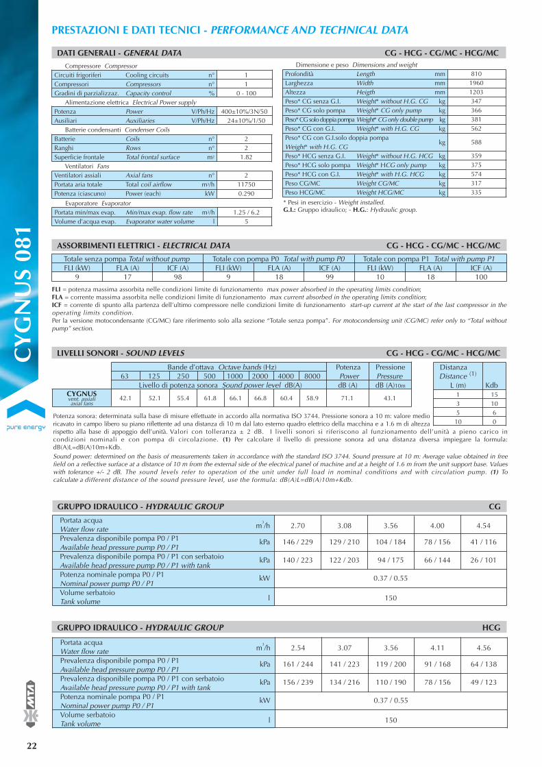
22
®PRESTAZIONI E DATI TECNICI - PERFORMANCE AND TECHNICAL DATA
FLI = potenza massima assorbita nelle condizioni limite di funzionamento max power absorbed in the operating limits condition; FLA = corrente massima assorbita nelle condizioni limite di funzionamento max current absorbed in the operating limits condition; ICF = corrente di spunto alla partenza dell’ultimo compressore nelle condizioni limite di funzionamento start-up current at the start of the last compressor in theoperating limits condition.Per la versione motocondensante (CG/MC) fare riferimento solo alla sezione “Totale senza pompa”. For motocondensing unit (CG/MC) refer only to “Total withoutpump” section.
Totale senza pompa Total without pump Totale con pompa P0 Total with pump P0 Totale con pompa P1 Total with pump P1FLI (kW) FLA (A) ICF (A) FLI (kW) FLA (A) ICF (A) FLI (kW) FLA (A) ICF (A)
9 17 98 9 18 99 10 18 100
ASSORBIMENTI ELETTRICI - ELECTRICAL DATA CG - HCG - CG/MC - HCG/MC
DATI GENERALI - GENERAL DATA CG - HCG - CG/MC - HCG/MC
11
0 - 100
400±10%/3N/5024±10%/1/50
22
1.82
2117500.290
Compressore CompressorCircuiti frigoriferi Cooling circuits n°Compressori Compressors n°Gradini di parzializzaz. Capacity control %
Alimentazione elettrica Electrical Power supplyPotenza Power V/Ph/HzAusiliari Auxiliaries V/Ph/Hz
Batterie condensanti Condenser CoilsBatterie Coils n°Ranghi Rows n°Superficie frontale Total frontal surface m2
Ventilatori FansVentilatori assiali Axial fans n°Portata aria totale Total coil airflow m3/hPotenza (ciascuno) Power (each) kW
LIVELLI SONORI - SOUND LEVELS CG - HCG - CG/MC - HCG/MC
Bande d’ottava Octave bands (Hz) Potenza Pressione63 125 250 500 1000 2000 4000 8000 Power Pressure
Livello di potenza sonora Sound power level dB(A) dB (A) dB (A)10m
42.1 52.1 55.4 61.8 66.1 66.8 60.4 58.9 71.1 43.1CYGNUSvent. assialiaxial fans
Portata acquaWater flow rate m
3/h 2.70 3.08 3.56 4.00 4.54
Prevalenza disponibile pompa P0 / P1 kPa 146 / 229 129 / 210 104 / 184 78 / 156 41 / 116Available head pressure pump P0 / P1 Prevalenza disponibile pompa P0 / P1 con serbatoio kPa 140 / 223 122 / 203 94 / 175 66 / 144 26 / 101Available head pressure pump P0 / P1 with tankPotenza nominale pompa P0 / P1 kW 0.37 / 0.55Nominal power pump P0 / P1Volume serbatoioTank volume l 150
GRUPPO IDRAULICO - HYDRAULIC GROUP CG
GRUPPO IDRAULICO - HYDRAULIC GROUP HCG
Portata acquaWater flow rate m
3/h 2.54 3.07 3.56 4.11 4.56
Prevalenza disponibile pompa P0 / P1 kPa 161 / 244 141 / 223 119 / 200 91 / 168 64 / 138Available head pressure pump P0 / P1 Prevalenza disponibile pompa P0 / P1 con serbatoio kPa 156 / 239 134 / 216 110 / 190 78 / 156 49 / 123Available head pressure pump P0 / P1 with tankPotenza nominale pompa P0 / P1 kW 0.37 / 0.55Nominal power pump P0 / P1Volume serbatoioTank volume l 150
* Pesi in esercizio - Weight installedG.I.: Gruppo idraulico; - H.S.: Hydraulic set.
81019601203347366381562
588
359375574317335
Dimensione e peso Dimensions and weightProfondità Length mmLarghezza Width mmAltezza Heigth mmPeso* CG senza G.I. Weight* without H.G. CG kgPeso* CG solo pompa Weight* CG only pump kgPeso* CG solo doppia pompa Weight* CG only double pump kgPeso* CG con G.I. Weight* with H.G. CG kgPeso* CG con G.I.solo doppia pompaWeight* with H.G. CG
kg
Peso* HCG senza G.I. Weight* without H.G. HCG kgPeso* HCG solo pompa Weight* HCG only pump kgPeso* HCG con G.I. Weight* with H.G. HCG kgPeso CG/MC Weight CG/MC kgPeso HCG/MC Weight HCG/MC kg
* Pesi in esercizio - Weight installed.G.I.: Gruppo idraulico; - H.G.: Hydraulic group.
Evaporatore Evaporator1.25 / 6.2
5Portata min/max evap. Min/max evap. flow rate m3/hVolume d’acqua evap. Evaporator water volume l
CY
GN
US
081
Potenza sonora: determinata sulla base di misure effettuate in accordo alla normativa ISO 3744. Pressione sonora a 10 m: valore medioricavato in campo libero su piano riflettente ad una distanza di 10 m dal lato esterno quadro elettrico della macchina e a 1.6 m di altezzarispetto alla base di appoggio dell’unità. Valori con tolleranza ± 2 dB. I livelli sonori si riferiscono al funzionamento dell’unità a pieno carico incondizioni nominali e con pompa di circolazione. (1) Per calcolare il livello di pressione sonora ad una distanza diversa impiegare la formula:dB(A)L=dB(A)10m+Kdb.Sound power: determined on the basis of measurements taken in accordance with the standard ISO 3744. Sound pressure at 10 m: Average value obtained in freefield on a reflective surface at a distance of 10 m from the external side of the electrical panel of machine and at a height of 1.6 m from the unit support base. Valueswith tolerance +/- 2 dB. The sound levels refer to operation of the unit under full load in nominal conditions and with circulation pump. (1) Tocalculate a different distance of the sound pressure level, use the formula: dB(A)L=dB(A)10m+Kdb.
Distanza (1)Distance
L (m) Kdb1 153 105 610 0

CY
GN
US
081
®
23
Conditioning your ambient, maximising your comfort.
PRESTAZIONI UNITÀ SOLO FREDDO - PERFORMANCE DATA COOLING MODE
56789
10
CG
Raffreddamento Temperatura aria esterna - External air temperature ta (°C)Cooling 27 30 32 35 38 43
Pf Pa Fw Pf Pa Fw Pf Pa Fw Pf Pa Fw Pf Pa Fw Pf Pa Fwtu (°C) (kW) (kW) (m3/h) (kW) (kW) (m3/h) (kW) (kW) (m3/h) (kW) (kW) (m3/h) (kW) (kW) (m3/h) (kW) (kW) (m3/h)
21.6 5.2 3.7 20.9 5.5 3.6 20.5 5.8 3.5 19.8 6.1 3.4 19.1 6.5 3.3 17.8 7.2 3.122.3 5.3 3.8 21.6 5.6 3.7 21.2 5.8 3.6 20.5 6.2 3.5 19.7 6.6 3.4 18.4 7.3 3.223.0 5.3 4.0 22.4 5.6 3.9 21.9 5.9 3.8 21.2 6.2 3.6 20.4 6.6 3.5 19.1 7.3 3.323.8 5.4 4.1 23.1 5.7 4.0 22.6 5.9 3.9 21.9 6.3 3.8 21.1 6.7 3.6 19.7 7.4 3.424.6 5.4 4.2 23.9 5.7 4.1 23.4 6.0 4.0 22.6 6.4 3.9 21.8 6.8 3.8 20.4 7.5 3.525.4 5.5 4.4 24.6 5.8 4.2 24.1 6.0 4.2 23.3 6.4 4.0 22.5 6.8 3.9 21.0 7.5 3.6
t max.(°C)
474747464645
3035404550
HCG
Riscaldamento Temperatura aria esterna - External air temperature ta (°C)Heating -5 0 5 7 12 15
Ph Pa Fw Ph Pa Fw Ph Pa Fw Ph Pa Fw Ph Pa Fw Ph Pa Fwtu (°C) (kW) (kW) (m3/h) (kW) (kW) (m3/h) (kW) (kW) (m3/h) (kW) (kW) (m3/h) (kW) (kW) (m3/h) (kW) (kW) (m3/h)
16.8 4.5 2.9 19.5 4.6 3.4 22.4 4.6 3.9 23.6 4.6 4.1 27.1 4.6 4.7 29.3 4.6 5.116.8 5.1 2.9 19.3 5.1 3.4 22.2 5.1 3.8 23.4 5.1 4.1 26.7 5.2 4.6 28.9 5.2 5.016.8 5.7 2.9 19.3 5.7 3.3 21.9 5.7 3.8 23.1 5.7 4.0 26.3 5.8 4.6 28.5 5.8 4.916.8 6.3 2.9 19.1 6.4 3.3 21.7 6.4 3.8 22.8 6.4 4.0 25.9 6.4 4.5 28.0 6.4 4.9
19.0 7.1 3.3 21.5 7.1 3.7 22.5 7.2 3.9 25.6 7.2 4.5 27.5 7.2 4.8
t min.(°C)
-10-10-10-6-2
56789
10
HCG
Raffreddamento Temperatura aria esterna - External air temperature ta (°C)Cooling 27 30 32 35 38 43
Pf Pa Fw Pf Pa Fw Pf Pa Fw Pf Pa Fw Pf Pa Fw Pf Pa Fwtu (°C) (kW) (kW) (m3/h) (kW) (kW) (m3/h) (kW) (kW) (m3/h) (kW) (kW) (m3/h) (kW) (kW) (m3/h) (kW) (kW) (m3/h)
20.7 5.2 3.6 20.1 5.5 3.5 19.7 5.8 3.4 19.0 6.1 3.3 18.4 6.5 3.2 17.2 7.2 3.021.4 5.2 3.7 20.8 5.6 3.6 20.4 5.8 3.5 19.7 6.2 3.4 19.0 6.6 3.3 17.8 7.3 3.122.2 5.3 3.8 21.5 5.6 3.7 21.1 5.9 3.6 20.4 6.2 3.5 19.7 6.6 3.4 18.4 7.3 3.222.9 5.3 3.9 22.3 5.7 3.8 21.8 5.9 3.8 21.1 6.3 3.6 20.3 6.7 3.5 19.0 7.4 3.323.7 5.4 4.1 23.0 5.7 4.0 22.5 6.0 3.9 21.8 6.3 3.8 21.0 6.7 3.6 19.7 7.4 3.424.5 5.4 4.2 23.7 5.8 4.1 23.3 6.0 4.0 22.5 6.4 3.9 21.7 6.8 3.7 20.3 7.5 3.5
t max.(°C)
474747464646
03578
10
CG/MC
Raffreddamento Temperatura aria esterna - External air temperature ta (°C)Cooling 27 30 32 35 38 43
Pf Pa Pf Pa Pf Pa Pf Pa Pf Pa Pf Pat evap. (°C) (kW) (kW) (kW) (kW) (kW) (kW) (kW) (kW) (kW) (kW) (kW) (kW)
18.38 5.16 17.80 5.48 17.41 5.70 16.79 6.06 16.15 6.43 15.04 7.1120.53 5.31 19.89 5.64 19.45 5.87 18.77 6.23 18.06 6.62 16.83 7.3122.04 5.42 21.35 5.76 20.88 5.99 20.16 6.36 19.41 6.75 18.10 7.4423.62 5.54 22.89 5.88 22.38 6.12 21.61 6.49 20.81 6.88 19.41 7.5824.43 5.60 23.67 5.94 23.16 6.18 22.36 6.55 21.53 6.95 20.09 7.6526.10 5.72 25.30 6.07 24.75 6.31 23.90 6.69 23.02 7.09 21.49 7.80
t max.(°C)
504846464645
tu: temperatura acqua uscita outlet water temperature; Pf: potenza frigorifera cooling capacity; Ph: potenza termica (HCygnus) heating capacity (HCygnus);Pa: potenza assorbita dai compressori power absorbed by the compressors; Fw: portata d’acqua (∆T = 5 °C) water flow rate (∆T = 5 °C).t evap: temperatura di evaporazione (DEW) evaporating temperature (DEW); t cond: temperatura di condensazione (DEW) condensing temperature (DEW);È permessa l’interpolazione dei valori ma non la loro estrapolazione. Interpolation is allowed. Extrapolation is not permitted. Per la determinazioni di Pf, Ph, Pa e Fwper ∆T diversi da 5 °C vedere la tabella ”Coefficienti correttivi per ∆T diversi da 5 °C”. To calculate Pf, Ph, Pa and Fw for ∆T ≠ 5 °C to examine the table ”Correctionfactors for ∆T ≠ 5 °C”.
03578
10
HCG/MC
Raffreddamento Temperatura aria esterna - External air temperature ta (°C)Cooling 27 30 32 35 38 43
Pf Pa Pf Pa Pf Pa Pf Pa Pf Pa Pf Pat evap. (°C) (kW) (kW) (kW) (kW) (kW) (kW) (kW) (kW) (kW) (kW) (kW) (kW)
17.71 5.11 17.15 5.42 16.76 5.65 16.17 6.00 15.55 6.38 14.47 7.0519.8 5.26 19.18 5.59 18.76 5.82 18.10 6.18 17.42 6.56 16.23 7.2421.28 5.37 20.62 5.70 20.17 5.93 19.46 6.30 18.73 6.68 17.46 7.3722.83 5.48 22.12 5.82 21.64 6.05 20.88 6.42 20.11 6.81 18.76 7.5123.63 5.54 22.90 5.88 22.39 6.12 21.62 6.49 20.82 6.88 19.42 7.5825.27 5.66 24.49 6.00 23.95 6.24 23.13 6.62 22.28 7.02 20.79 7.73
t max.(°C)
484746464544
354045505560
HCG/MC
Riscaldamento Temperatura aria esterna - External air temperature ta (°C)Heating -5 0 5 7 12 15
Ph Pa Ph Pa Ph Pa Ph Pa Ph Pa Ph Pat cond. (°C) (kW) (kW) (kW) (kW) (kW) (kW) (kW) (kW) (kW) (kW) (kW) (kW)
17.03 4.22 19.85 4.24 22.84 4.26 24.14 4.27 27.84 4.27 30.27 4.2716.93 4.63 19.66 4.66 22.56 4.68 23.82 4.68 27.31 4.69 29.71 4.6916.80 5.17 19.43 5.20 22.21 5.22 23.42 5.23 26.77 5.23 29.15 5.2316.71 5.77 19.23 5.80 21.90 5.83 23.07 5.83 26.30 5.84 28.53 5.8516.67 6.44 19.01 6.48 21.55 6.51 22.66 6.51 25.71 6.53 27.84 6.53
18.83 7.24 21.25 7.27 22.31 7.28 25.16 7.29 27.21 7.30
t min.(°C)
-9-10-10-11-6-2
PRESTAZIONI POMPA DI CALORE - PERFORMANCE DATA HEAT PUMP
PRESTAZIONI UNITÀ MOTOCONDENSANTE - PERFORMANCE DATA CONDENSING UNIT
PRESTAZIONI UNITÀ MOTOCONDENSANTE REVERSIBILE - PERFORMANCE DATA REVERSIBLE CONDENSING UNIT

24
®PRESTAZIONI E DATI TECNICI - PERFORMANCE AND TECHNICAL DATA
FLI = potenza massima assorbita nelle condizioni limite di funzionamento max power absorbed in the operating limits condition; FLA = corrente massima assorbita nelle condizioni limite di funzionamento max current absorbed in the operating limits condition; ICF = corrente di spunto alla partenza dell’ultimo compressore nelle condizioni limite di funzionamento start-up current at the start of the last compressor in theoperating limits condition.Per la versione motocondensante (CG/MC) fare riferimento solo alla sezione “Totale senza pompa”. For motocondensing unit (CG/MC) refer only to “Total withoutpump” section.
Totale senza pompa Total without pump Totale con pompa P0 Total with pump P0 Totale con pompa P1 Total with pump P1FLI (kW) FLA (A) ICF (A) FLI (kW) FLA (A) ICF (A) FLI (kW) FLA (A) ICF (A)
12 22 120 13 24 121 13 24 122
ASSORBIMENTI ELETTRICI - ELECTRICAL DATA CG - HCG - CG/MC - HCG/MC
DATI GENERALI - GENERAL DATA CG - HCG - CG/MC - HCG/MC
11
0 - 100
400±10%/3N/5024±10%/1/50
23
1.82
2115000.290
Compressore CompressorCircuiti frigoriferi Cooling circuits n°Compressori Compressors n°Gradini di parzializzaz. Capacity control %
Alimentazione elettrica Electrical Power supplyPotenza Power V/Ph/HzAusiliari Auxiliaries V/Ph/Hz
Batterie condensanti Condenser CoilsBatterie Coils n°Ranghi Rows n°Superficie frontale Total frontal surface m2
Ventilatori FansVentilatori assiali Axial fans n°Portata aria totale Total coil airflow m3/hPotenza (ciascuno) Power (each) kW
LIVELLI SONORI - SOUND LEVELS CG - HCG - CG/MC - HCG/MC
Bande d’ottava Octave bands (Hz) Potenza Pressione63 125 250 500 1000 2000 4000 8000 Power Pressure
Livello di potenza sonora Sound power level dB(A) dB (A) dB (A)10m
42.2 52.2 55.8 65.8 68.5 70.8 64.3 59.2 74.3 46.3CYGNUSvent. assialiaxial fans
Portata acquaWater flow rate m
3/h 3.50 3.84 4.40 4.91 5.14
Prevalenza disponibile pompa P0 / P1 kPa 143 / 228 127 / 210 95 / 173 63 / 134 47 / 114Available head pressure pump P0 / P1 Prevalenza disponibile pompa P0 / P1 con serbatoio kPa 138 / 219 120 / 198 87 / 157 53 / 114 35 / 93Available head pressure pump P0 / P1 with tankPotenza nominale pompa P0 / P1 kW 0.37 / 0.55Nominal power pump P0 / P1Volume serbatoioTank volume l 150
GRUPPO IDRAULICO - HYDRAULIC GROUP CG
GRUPPO IDRAULICO - HYDRAULIC GROUP HCG
Portata acquaWater flow rate m
3/h 3.56 3.91 4.32 4.72 5.30
Prevalenza disponibile pompa P0 / P1 kPa 159 / 234 146 / 216 127 / 191 108 / 164 75 / 116Available head pressure pump P0 / P1 Prevalenza disponibile pompa P0 / P1 con serbatoio kPa 144 / 224 127 / 204 104 / 176 80 / 146 40 / 63Available head pressure pump P0 / P1 with tankPotenza nominale pompa P0 / P1 kW 0.37 / 0.55Nominal power pump P0 / P1Volume serbatoioTank volume l 150
* Pesi in esercizio - Weight installedG.I.: Gruppo idraulico; - H.S.: Hydraulic set.
81019601203365376402580
606
377392592327345
Dimensione e peso Dimensions and weightProfondità Length mmLarghezza Width mmAltezza Heigth mmPeso* CG senza G.I. Weight* without H.G. CG kgPeso* CG solo pompa Weight* CG only pump kgPeso* CG solo doppia pompa Weight* CG only double pump kgPeso* CG con G.I. Weight* with H.G. CG kgPeso* CG con G.I.solo doppia pompaWeight* with H.G. CG
kg
Peso* HCG senza G.I. Weight* without H.G. HCG kgPeso* HCG solo pompa Weight* HCG only pump kgPeso* HCG con G.I. Weight* with H.G. HCG kgPeso CG/MC Weight CG/MC kgPeso HCG/MC Weight HCG/MC kg
* Pesi in esercizio - Weight installed.G.I.: Gruppo idraulico; - H.G.: Hydraulic group.
Evaporatore Evaporator1.6 / 8.3
5Portata min/max evap. Min/max evap. flow rate m3/hVolume d’acqua evap. Evaporator water volume l
CY
GN
US
101
Potenza sonora: determinata sulla base di misure effettuate in accordo alla normativa ISO 3744. Pressione sonora a 10 m: valore medioricavato in campo libero su piano riflettente ad una distanza di 10 m dal lato esterno quadro elettrico della macchina e a 1.6 m di altezzarispetto alla base di appoggio dell’unità. Valori con tolleranza ± 2 dB. I livelli sonori si riferiscono al funzionamento dell’unità a pieno carico incondizioni nominali e con pompa di circolazione. (1) Per calcolare il livello di pressione sonora ad una distanza diversa impiegare la formula:dB(A)L=dB(A)10m+Kdb.Sound power: determined on the basis of measurements taken in accordance with the standard ISO 3744. Sound pressure at 10 m: Average value obtained in freefield on a reflective surface at a distance of 10 m from the external side of the electrical panel of machine and at a height of 1.6 m from the unit support base. Valueswith tolerance +/- 2 dB. The sound levels refer to operation of the unit under full load in nominal conditions and with circulation pump. (1) Tocalculate a different distance of the sound pressure level, use the formula: dB(A)L=dB(A)10m+Kdb.
Distanza (1)Distance
L (m) Kdb1 153 105 610 0

CY
GN
US
101
®
25
Conditioning your ambient, maximising your comfort.
PRESTAZIONI UNITÀ SOLO FREDDO - PERFORMANCE DATA COOLING MODE
56789
10
CG
Raffreddamento Temperatura aria esterna - External air temperature ta (°C)Cooling 27 30 32 35 38 43
Pf Pa Fw Pf Pa Fw Pf Pa Fw Pf Pa Fw Pf Pa Fw Pf Pa Fwtu (°C) (kW) (kW) (m3/h) (kW) (kW) (m3/h) (kW) (kW) (m3/h) (kW) (kW) (m3/h) (kW) (kW) (m3/h) (kW) (kW) (m3/h)
29.3 7.3 5.0 28.3 7.7 4.9 27.7 8.1 4.8 26.6 8.6 4.6 25.6 9.2 4.4 23.7 10.3 4.130.3 7.3 5.2 29.3 7.8 5.0 28.6 8.2 4.9 27.6 8.7 4.7 26.5 9.3 4.6 24.5 10.4 4.231.3 7.4 5.4 30.3 7.9 5.2 29.6 8.2 5.1 28.5 8.8 4.9 27.4 9.4 4.7 25.4 10.5 4.432.3 7.5 5.6 31.3 8.0 5.4 30.6 8.3 5.3 29.4 8.9 5.1 28.3 9.5 4.9 26.2 10.6 4.533.4 7.5 5.8 32.3 8.0 5.6 31.6 8.4 5.4 30.4 9.0 5.2 29.2 9.6 5.0 27.1 10.7 4.734.5 7.6 5.9 33.4 8.1 5.7 32.6 8.5 5.6 31.4 9.0 5.4 30.2 9.7 5.2 28.0 10.8 4.8
t max.(°C)
474746464545
3035404550
HCG
Riscaldamento Temperatura aria esterna - External air temperature ta (°C)Heating -5 0 5 7 12 15
Ph Pa Fw Ph Pa Fw Ph Pa Fw Ph Pa Fw Ph Pa Fw Ph Pa Fwtu (°C) (kW) (kW) (m3/h) (kW) (kW) (m3/h) (kW) (kW) (m3/h) (kW) (kW) (m3/h) (kW) (kW) (m3/h) (kW) (kW) (m3/h)
22.7 6.2 3.9 26.0 6.2 4.5 29.8 6.3 5.2 31.4 6.3 5.4 35.8 6.3 6.2 38.7 6.3 6.722.6 7.0 3.9 25.9 7.0 4.5 29.5 7.0 5.1 31.1 7.0 5.4 35.4 7.0 6.1 38.5 7.0 6.722.6 7.9 3.9 25.8 7.9 4.5 29.2 7.9 5.1 30.8 7.9 5.3 35.6 7.9 6.2 37.7 7.9 6.622.6 8.9 3.9 25.7 8.9 4.5 29.0 8.9 5.0 30.4 8.9 5.3 35.0 8.9 6.1 37.0 8.9 6.4
25.6 10.1 4.5 28.8 10.1 5.0 30.3 10.1 5.3 34.5 10.0 6.0 36.5 10.0 6.4
t min.(°C)
-9-9-10-7-2
56789
10
HCG
Raffreddamento Temperatura aria esterna - External air temperature ta (°C)Cooling 27 30 32 35 38 43
Pf Pa Fw Pf Pa Fw Pf Pa Fw Pf Pa Fw Pf Pa Fw Pf Pa Fwtu (°C) (kW) (kW) (m3/h) (kW) (kW) (m3/h) (kW) (kW) (m3/h) (kW) (kW) (m3/h) (kW) (kW) (m3/h) (kW) (kW) (m3/h)
28.1 7.2 4.8 27.2 7.7 4.7 26.6 8.0 4.6 25.6 8.6 4.4 24.6 9.2 4.2 22.8 10.3 3.929.1 7.3 5.0 28.2 7.8 4.8 27.5 8.1 4.7 26.5 8.7 4.6 25.4 9.3 4.4 23.6 10.3 4.130.1 7.3 5.2 29.1 7.8 5.0 28.4 8.2 4.9 27.4 8.7 4.7 26.3 9.3 4.5 24.4 10.4 4.231.1 7.4 5.4 30.1 7.9 5.2 29.4 8.2 5.1 28.3 8.8 4.9 27.2 9.4 4.7 25.2 10.5 4.332.1 7.5 5.5 31.1 8.0 5.4 30.3 8.3 5.2 29.2 8.9 5.0 28.1 9.5 4.8 26.1 10.6 4.533.1 7.5 5.7 32.1 8.0 5.5 31.3 8.4 5.4 30.2 9.0 5.2 29.0 9.6 5.0 26.9 10.7 4.6
t max.(°C)
474746464645
03578
10
CG/MC
Raffreddamento Temperatura aria esterna - External air temperature ta (°C)Cooling 27 30 32 35 38 43
Pf Pa Pf Pa Pf Pa Pf Pa Pf Pa Pf Pat evap. (°C) (kW) (kW) (kW) (kW) (kW) (kW) (kW) (kW) (kW) (kW) (kW) (kW)
24.99 7.18 24.13 7.65 23.54 7.99 22.62 8.53 21.66 9.11 19.97 10.1927.91 7.40 26.96 7.89 26.31 8.23 25.29 8.78 24.24 9.37 22.38 10.4629.96 7.56 28.95 8.05 28.25 8.40 27.17 8.96 26.05 9.56 24.08 10.6532.09 7.72 31.01 8.22 30.27 8.58 29.12 9.14 27.93 9.74 25.84 10.8533.18 7.81 32.07 8.31 31.31 8.67 30.12 9.23 28.89 9.84 26.74 10.9535.43 7.98 34.25 8.49 33.44 8.85 32.18 9.43 30.88 10.04 28.60 11.15
t max.(°C)
504848474645
tu: temperatura acqua uscita outlet water temperature; Pf: potenza frigorifera cooling capacity; Ph: potenza termica (HCygnus) heating capacity (HCygnus);Pa: potenza assorbita dai compressori power absorbed by the compressors; Fw: portata d’acqua (∆T = 5 °C) water flow rate (∆T = 5 °C).t evap: temperatura di evaporazione (DEW) evaporating temperature (DEW); t cond: temperatura di condensazione (DEW) condensing temperature (DEW);È permessa l’interpolazione dei valori ma non la loro estrapolazione. Interpolation is allowed. Extrapolation is not permitted. Per la determinazioni di Pf, Ph, Pa e Fwper ∆T diversi da 5 °C vedere la tabella ”Coefficienti correttivi per ∆T diversi da 5 °C”. To calculate Pf, Ph, Pa and Fw for ∆T ≠ 5 °C to examine the table ”Correctionfactors for ∆T ≠ 5 °C”.
03578
10
HCG/MC
Raffreddamento Temperatura aria esterna - External air temperature ta (°C)Cooling 27 30 32 35 38 43
Pf Pa Pf Pa Pf Pa Pf Pa Pf Pa Pf Pat evap. (°C) (kW) (kW) (kW) (kW) (kW) (kW) (kW) (kW) (kW) (kW) (kW) (kW)
24.07 7.11 23.24 7.58 22.67 7.91 21.77 8.45 20.84 9.03 19.20 10.1026.93 7.33 26.01 7.81 25.38 8.15 24.39 8.70 23.37 9.29 21.57 10.3728.94 7.48 27.96 7.97 27.28 8.32 26.23 8.87 25.14 9.46 23.23 10.5531.03 7.64 29.98 8.14 29.26 8.49 28.15 9.05 26.99 9.65 24.96 10.7532.10 7.72 31.02 8.22 30.28 8.58 29.13 9.14 27.94 9.74 25.85 10.8534.31 7.89 33.17 8.40 32.38 8.76 31.16 9.33 29.89 9.94 27.68 11.05
t max.(°C)
504948474746
354045505560
HCG/MC
Riscaldamento Temperatura aria esterna - External air temperature ta (°C)Heating -5 0 5 7 12 15
Ph Pa Ph Pa Ph Pa Ph Pa Ph Pa Ph Pat cond. (°C) (kW) (kW) (kW) (kW) (kW) (kW) (kW) (kW) (kW) (kW) (kW) (kW)
22.72 5.81 26.40 5.82 30.40 5.83 32.19 5.83 37.00 5.83 40.23 5.8222.59 6.40 26.16 6.41 30.05 6.42 31.78 6.42 36.45 6.42 39.64 6.4122.47 7.20 25.91 7.21 29.65 7.21 31.32 7.21 35.81 7.20 38.82 7.1822.35 8.11 25.65 8.12 29.23 8.12 30.83 8.11 35.12 8.10 37.95 8.0822.33 9.17 25.38 9.17 28.79 9.16 30.31 9.16 34.42 9.14 37.18 9.11
25.22 10.37 28.45 10.36 29.90 10.35 33.75 10.32 36.38 10.30
t min.(°C)
-8-9-10-10-6-2
PRESTAZIONI POMPA DI CALORE - PERFORMANCE DATA HEAT PUMP
PRESTAZIONI UNITÀ MOTOCONDENSANTE - PERFORMANCE DATA CONDENSING UNIT
PRESTAZIONI UNITÀ MOTOCONDENSANTE REVERSIBILE - PERFORMANCE DATA REVERSIBLE CONDENSING UNIT
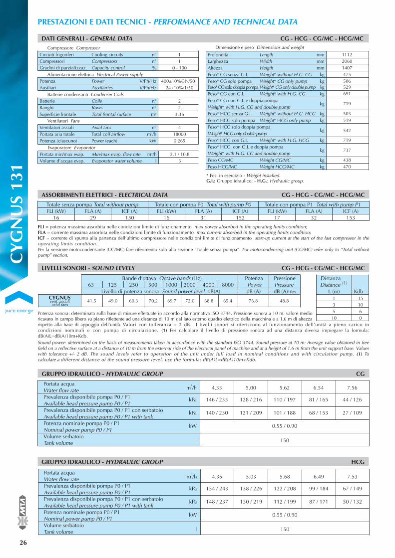
26
®PRESTAZIONI E DATI TECNICI - PERFORMANCE AND TECHNICAL DATA
FLI = potenza massima assorbita nelle condizioni limite di funzionamento max power absorbed in the operating limits condition; FLA = corrente massima assorbita nelle condizioni limite di funzionamento max current absorbed in the operating limits condition; ICF = corrente di spunto alla partenza dell’ultimo compressore nelle condizioni limite di funzionamento start-up current at the start of the last compressor in theoperating limits condition.Per la versione motocondensante (CG/MC) fare riferimento solo alla sezione “Totale senza pompa”. For motocondensing unit (CG/MC) refer only to “Total withoutpump” section.
Totale senza pompa Total without pump Totale con pompa P0 Total with pump P0 Totale con pompa P1 Total with pump P1FLI (kW) FLA (A) ICF (A) FLI (kW) FLA (A) ICF (A) FLI (kW) FLA (A) ICF (A)
16 29 150 16 31 152 17 32 153
ASSORBIMENTI ELETTRICI - ELECTRICAL DATA CG - HCG - CG/MC - HCG/MC
DATI GENERALI - GENERAL DATA CG - HCG - CG/MC - HCG/MC
11
0 - 100
400±10%/3N/5024±10%/1/50
22
3.36
4180000.265
Compressore CompressorCircuiti frigoriferi Cooling circuits n°Compressori Compressors n°Gradini di parzializzaz. Capacity control %
Alimentazione elettrica Electrical Power supplyPotenza Power V/Ph/HzAusiliari Auxiliaries V/Ph/Hz
Batterie condensanti Condenser CoilsBatterie Coils n°Ranghi Rows n°Superficie frontale Total frontal surface m2
Ventilatori FansVentilatori assiali Axial fans n°Portata aria totale Total coil airflow m3/hPotenza (ciascuno) Power (each) kW
LIVELLI SONORI - SOUND LEVELS CG - HCG - CG/MC - HCG/MC
Bande d’ottava Octave bands (Hz) Potenza Pressione63 125 250 500 1000 2000 4000 8000 Power Pressure
Livello di potenza sonora Sound power level dB(A) dB (A) dB (A)10m
41.5 49.0 60.3 70.2 69.7 72.0 68.8 65.4 76.8 48.8CYGNUSvent. assialiaxial fans
Portata acquaWater flow rate m
3/h 4.33 5.00 5.62 6.54 7.56
Prevalenza disponibile pompa P0 / P1 kPa 146 / 235 128 / 216 110 / 197 81 / 165 44 / 126Available head pressure pump P0 / P1 Prevalenza disponibile pompa P0 / P1 con serbatoio kPa 140 / 230 121 / 209 101 / 188 68 / 153 27 / 109Available head pressure pump P0 / P1 with tankPotenza nominale pompa P0 / P1 kW 0.55 / 0.90Nominal power pump P0 / P1Volume serbatoioTank volume l 150
GRUPPO IDRAULICO - HYDRAULIC GROUP CG
GRUPPO IDRAULICO - HYDRAULIC GROUP HCG
Portata acquaWater flow rate m
3/h 4.35 5.03 5.68 6.49 7.53
Prevalenza disponibile pompa P0 / P1 kPa 154 / 243 138 / 226 122 / 208 99 / 184 67 / 149Available head pressure pump P0 / P1 Prevalenza disponibile pompa P0 / P1 con serbatoio kPa 148 / 237 130 / 219 112 / 199 87 / 171 50 / 132Available head pressure pump P0 / P1 with tankPotenza nominale pompa P0 / P1 kW 0.55 / 0.90Nominal power pump P0 / P1Volume serbatoioTank volume l 150
* Pesi in esercizio - Weight installedG.I.: Gruppo idraulico; - H.S.: Hydraulic set.
111220601407475506529691
719
503519
542
719
737
438470
Dimensione e peso Dimensions and weight
Profondità Length mmLarghezza Width mmAltezza Heigth mmPeso* CG senza G.I. Weight* without H.G. CG kgPeso* CG solo pompa Weight* CG only pump kgPeso* CG solo doppia pompa Weight* CG only double pump kgPeso* CG con G.I. Weight* with H.G. CG kgPeso* CG con G.I. e doppia pompaWeight* with H.G. CG and double pump
kg
Peso* HCG senza G.I. Weight* without H.G. HCG kgPeso* HCG solo pompa Weight* HCG only pump kgPeso* HCG solo doppia pompa
kgWeight* HCG only double pumpPeso* HCG con G.I. Weight* with H.G. HCG kgPeso* HCG con G.I. e doppia pompaWeight* with H.G. CG and double pump
kg
Peso CG/MC Weight CG/MC kgPeso HCG/MC Weight HCG/MC kg
* Pesi in esercizio - Weight installed.G.I.: Gruppo idraulico; - H.G.: Hydraulic group.
Evaporatore Evaporator2.1 / 10.8
5Portata min/max evap. Min/max evap. flow rate m3/hVolume d’acqua evap. Evaporator water volume l
CY
GN
US
131
Potenza sonora: determinata sulla base di misure effettuate in accordo alla normativa ISO 3744. Pressione sonora a 10 m: valore medioricavato in campo libero su piano riflettente ad una distanza di 10 m dal lato esterno quadro elettrico della macchina e a 1.6 m di altezzarispetto alla base di appoggio dell’unità. Valori con tolleranza ± 2 dB. I livelli sonori si riferiscono al funzionamento dell’unità a pieno carico incondizioni nominali e con pompa di circolazione. (1) Per calcolare il livello di pressione sonora ad una distanza diversa impiegare la formula:dB(A)L=dB(A)10m+Kdb.Sound power: determined on the basis of measurements taken in accordance with the standard ISO 3744. Sound pressure at 10 m: Average value obtained in freefield on a reflective surface at a distance of 10 m from the external side of the electrical panel of machine and at a height of 1.6 m from the unit support base. Valueswith tolerance +/- 2 dB. The sound levels refer to operation of the unit under full load in nominal conditions and with circulation pump. (1) Tocalculate a different distance of the sound pressure level, use the formula: dB(A)L=dB(A)10m+Kdb.
Distanza (1)Distance
L (m) Kdb1 153 105 610 0

CY
GN
US
131
®
27
Conditioning your ambient, maximising your comfort.
PRESTAZIONI UNITÀ SOLO FREDDO - PERFORMANCE DATA COOLING MODE
56789
10
CG
Raffreddamento Temperatura aria esterna - External air temperature ta (°C)Cooling 27 30 32 35 38 43
Pf Pa Fw Pf Pa Fw Pf Pa Fw Pf Pa Fw Pf Pa Fw Pf Pa Fwtu (°C) (kW) (kW) (m3/h) (kW) (kW) (m3/h) (kW) (kW) (m3/h) (kW) (kW) (m3/h) (kW) (kW) (m3/h) (kW) (kW) (m3/h)
38.0 9.6 6.5 36.8 10.2 6.3 36.0 10.6 6.2 34.7 11.2 6.0 33.4 11.9 5.7 31.1 13.1 5.439.3 9.7 6.8 38.1 10.3 6.6 37.2 10.7 6.4 35.9 11.3 6.2 34.5 12.0 5.9 32.2 13.2 5.540.6 9.8 7.0 39.3 10.4 6.8 38.5 10.8 6.6 37.1 11.4 6.4 35.7 12.1 6.1 33.3 13.3 5.742.0 9.9 7.2 40.7 10.5 7.0 39.8 10.9 6.8 38.4 11.5 6.6 36.9 12.2 6.4 34.4 13.4 5.943.3 10.0 7.5 42.0 10.6 7.2 41.1 11.0 7.1 39.6 11.6 6.8 38.1 12.3 6.6 35.5 13.5 6.144.7 10.1 7.7 43.3 10.7 7.5 42.4 11.1 7.3 40.9 11.7 7.0 39.4 12.4 6.8 36.7 13.7 6.3
t max.(°C)
474646454545
3035404550
HCG
Riscaldamento Temperatura aria esterna - External air temperature ta (°C)Heating -5 0 5 7 12 15
Ph Pa Fw Ph Pa Fw Ph Pa Fw Ph Pa Fw Ph Pa Fw Ph Pa Fwtu (°C) (kW) (kW) (m3/h) (kW) (kW) (m3/h) (kW) (kW) (m3/h) (kW) (kW) (m3/h) (kW) (kW) (m3/h) (kW) (kW) (m3/h)
29.9 8.1 5.2 34.5 8.2 6.0 39.6 8.3 6.8 41.8 8.3 7.2 47.7 8.3 8.2 51.7 8.4 8.929.8 9.0 5.2 34.2 9.1 5.9 39.1 9.1 6.8 41.3 9.2 7.2 47.1 9.3 8.2 51.1 9.3 8.929.7 10.0 5.2 34.0 10.1 5.9 38.7 10.2 6.7 40.8 10.2 7.1 46.5 10.3 8.1 50.1 10.3 8.729.6 11.2 5.2 33.7 11.3 5.9 38.3 11.3 6.7 40.2 11.3 7.0 45.6 11.4 7.9 49.3 11.4 8.6
33.6 12.5 5.9 37.9 12.6 6.6 39.8 12.6 6.9 44.9 12.7 7.8 48.9 12.7 8.5
t min.(°C)
-10-10-10-8-3
56789
10
HCG
Raffreddamento Temperatura aria esterna - External air temperature ta (°C)Cooling 27 30 32 35 38 43
Pf Pa Fw Pf Pa Fw Pf Pa Fw Pf Pa Fw Pf Pa Fw Pf Pa Fwtu (°C) (kW) (kW) (m3/h) (kW) (kW) (m3/h) (kW) (kW) (m3/h) (kW) (kW) (m3/h) (kW) (kW) (m3/h) (kW) (kW) (m3/h)
36.4 9.5 6.3 35.3 10.1 6.1 34.5 10.5 5.9 33.2 11.1 5.7 32.0 11.8 5.5 29.8 13.0 5.137.6 9.6 6.5 36.5 10.2 6.3 35.6 10.6 6.1 34.4 11.2 5.9 33.1 11.9 5.7 30.8 13.1 5.338.9 9.7 6.7 37.7 10.3 6.5 36.8 10.7 6.3 35.5 11.3 6.1 34.2 12.0 5.9 31.9 13.2 5.540.2 9.8 6.9 38.9 10.4 6.7 38.1 10.8 6.6 36.7 11.4 6.3 35.3 12.1 6.1 32.9 13.3 5.741.5 9.9 7.2 40.2 10.5 6.9 39.3 10.9 6.8 37.9 11.6 6.5 36.5 12.2 6.3 34.0 13.5 5.942.9 10.0 7.4 41.5 10.6 7.2 40.6 11.0 7.0 39.2 11.7 6.7 37.7 12.3 6.5 35.1 13.6 6.1
t max.(°C)
474646464545
03578
10
CG/MC
Raffreddamento Temperatura aria esterna - External air temperature ta (°C)Cooling 27 30 32 35 38 43
Pf Pa Pf Pa Pf Pa Pf Pa Pf Pa Pf Pat evap. (°C) (kW) (kW) (kW) (kW) (kW) (kW) (kW) (kW) (kW) (kW) (kW) (kW)
32.50 9.48 31.42 10.05 30.69 10.44 29.55 11.06 28.38 11.72 26.34 12.9036.29 9.79 35.10 10.37 34.29 10.77 33.03 11.40 31.73 12.07 29.48 13.2638.96 10.01 37.69 10.59 36.82 11.00 35.47 11.64 34.09 12.31 31.68 13.5141.74 10.24 40.38 10.83 39.45 11.24 38.02 11.88 36.54 12.56 33.97 13.7743.17 10.36 41.77 10.95 40.81 11.36 39.32 12.00 37.80 12.69 35.15 13.9046.12 10.60 44.62 11.19 43.59 11.61 42.01 12.26 40.39 12.95 37.58 14.17
t max.(°C)
494847464645
tu: temperatura acqua uscita outlet water temperature; Pf: potenza frigorifera cooling capacity; Ph: potenza termica (HCygnus) heating capacity (HCygnus);Pa: potenza assorbita dai compressori power absorbed by the compressors; Fw: portata d’acqua (∆T = 5 °C) water flow rate (∆T = 5 °C).t evap: temperatura di evaporazione (DEW) evaporating temperature (DEW); t cond: temperatura di condensazione (DEW) condensing temperature (DEW);È permessa l’interpolazione dei valori ma non la loro estrapolazione. Interpolation is allowed. Extrapolation is not permitted. Per la determinazioni di Pf, Ph, Pa e Fwper ∆T diversi da 5 °C vedere la tabella ”Coefficienti correttivi per ∆T diversi da 5 °C”. To calculate Pf, Ph, Pa and Fw for ∆T ≠ 5 °C to examine the table ”Correctionfactors for ∆T ≠ 5 °C”.
03578
10
HCG/MC
Raffreddamento Temperatura aria esterna - External air temperature ta (°C)Cooling 27 30 32 35 38 43
Pf Pa Pf Pa Pf Pa Pf Pa Pf Pa Pf Pat evap. (°C) (kW) (kW) (kW) (kW) (kW) (kW) (kW) (kW) (kW) (kW) (kW) (kW)
31.30 9.38 30.27 9.94 29.55 10.34 28.46 10.95 27.32 11.61 25.35 12.7935.01 9.69 33.86 10.26 33.08 10.66 31.86 11.29 30.60 11.95 28.42 13.1437.63 9.90 36.40 10.48 35.55 10.88 34.25 11.52 32.91 12.19 30.58 13.3940.36 10.13 39.04 10.71 38.14 11.12 36.75 11.76 35.31 12.43 32.83 13.6441.76 10.24 40.40 10.83 39.47 11.24 38.03 11.88 36.55 12.56 33.99 13.7744.65 10.48 43.20 11.07 42.20 11.48 40.67 12.13 39.10 12.82 36.37 14.04
t max.(°C)
494747464544
354045505560
HCG/MC
Riscaldamento Temperatura aria esterna - External air temperature ta (°C)Heating -5 0 5 7 12 15
Ph Pa Ph Pa Ph Pa Ph Pa Ph Pa Ph Pat cond. (°C) (kW) (kW) (kW) (kW) (kW) (kW) (kW) (kW) (kW) (kW) (kW) (kW)
30.06 7.58 34.93 7.65 40.32 7.70 42.72 7.72 49.16 7.76 53.46 7.7829.85 8.32 34.58 8.39 39.81 8.44 42.14 8.46 48.39 8.50 52.47 8.5229.71 9.27 34.28 9.34 39.19 9.39 41.43 9.41 47.45 9.45 51.47 9.4729.54 10.33 33.92 10.40 38.63 10.45 40.80 10.47 46.39 10.51 50.37 10.5329.44 11.52 33.51 11.59 38.01 11.64 40.08 11.66 45.45 11.70 49.17 11.72
33.18 12.91 37.47 12.97 39.28 12.99 44.49 13.03 48.05 13.05
t min.(°C)
-8-9-10-10-6-1
PRESTAZIONI POMPA DI CALORE - PERFORMANCE DATA HEAT PUMP
PRESTAZIONI UNITÀ MOTOCONDENSANTE - PERFORMANCE DATA CONDENSING UNIT
PRESTAZIONI UNITÀ MOTOCONDENSANTE REVERSIBILE - PERFORMANCE DATA REVERSIBLE CONDENSING UNIT

28
®PRESTAZIONI E DATI TECNICI - PERFORMANCE AND TECHNICAL DATA
FLI = potenza massima assorbita nelle condizioni limite di funzionamento max power absorbed in the operating limits condition; FLA = corrente massima assorbita nelle condizioni limite di funzionamento max current absorbed in the operating limits condition; ICF = corrente di spunto alla partenza dell’ultimo compressore nelle condizioni limite di funzionamento start-up current at the start of the last compressor in theoperating limits condition.Per la versione motocondensante (CG/MC) fare riferimento solo alla sezione “Totale senza pompa”. For motocondensing unit (CG/MC) refer only to “Total withoutpump” section.
Totale senza pompa Total without pump Totale con pompa P0 Total with pump P0 Totale con pompa P1 Total with pump P1FLI (kW) FLA (A) ICF (A) FLI (kW) FLA (A) ICF (A) FLI (kW) FLA (A) ICF (A)
18 34 175 19 36 177 20 37 178
ASSORBIMENTI ELETTRICI - ELECTRICAL DATA CG - HCG - CG/MC - HCG/MC
DATI GENERALI - GENERAL DATA CG - HCG - CG/MC - HCG/MC
11
0 - 100
400±10%/3N/5024±10%/1/50
23
3.36
4176000.265
Compressore CompressorCircuiti frigoriferi Cooling circuits n°Compressori Compressors n°Gradini di parzializzaz. Capacity control %
Alimentazione elettrica Electrical Power supplyPotenza Power V/Ph/HzAusiliari Auxiliaries V/Ph/Hz
Batterie condensanti Condenser CoilsBatterie Coils n°Ranghi Rows n°Superficie frontale Total frontal surface m2
Ventilatori FansVentilatori assiali Axial fans n°Portata aria totale Total coil airflow m3/hPotenza (ciascuno) Power (each) kW
Portata acquaWater flow rate m
3/h 5.12 6.02 7.07 7.55 8.09
Prevalenza disponibile pompa P0 / P1 kPa 162 / 245 134 / 217 97 / 180 78 / 162 56 / 140Available head pressure pump P0 / P1 Prevalenza disponibile pompa P0 / P1 con serbatoio kPa 153 / 237 121 / 205 79 / 164 58 / 143 32 / 118Available head pressure pump P0 / P1 with tankPotenza nominale pompa P0 / P1 kW 0.55 / 0.90Nominal power pump P0 / P1Volume serbatoioTank volume l 150
GRUPPO IDRAULICO - HYDRAULIC GROUP CG
GRUPPO IDRAULICO - HYDRAULIC GROUP HCG
Portata acquaWater flow rate m
3/h 5.20 6.02 6.96 7.28 8.19
Prevalenza disponibile pompa P0 / P1 kPa 155 / 244 133 / 221 104 / 191 94 / 180 62 / 147Available head pressure pump P0 / P1 Prevalenza disponibile pompa P0 / P1 con serbatoio kPa 146 / 236 121 / 209 88 / 175 76 / 163 40 / 125Available head pressure pump P0 / P1 with tankPotenza nominale pompa P0 / P1 kW 0.55 / 0.90Nominal power pump P0 / P1Volume serbatoioTank volume l 150
* Pesi in esercizio - Weight installedG.I.: Gruppo idraulico; - H.S.: Hydraulic set.
111220601417510544570726
751
538554
580
754
769
468502
Dimensione e peso Dimensions and weight
Profondità Length mmLarghezza Width mmAltezza Heigth mmPeso* CG senza G.I. Weight* without H.G. CG kgPeso* CG solo pompa Weight* CG only pump kgPeso* CG solo doppia pompa Weight* CG only double pump kgPeso* CG con G.I. Weight* with H.G. CG kgPeso* CG con G.I. e doppia pompaWeight* with H.G. CG and double pump
kg
Peso* HCG senza G.I. Weight* without H.G. HCG kgPeso* HCG solo pompa Weight* HCG only pump kgPeso* HCG solo doppia pompa
kgWeight* HCG only double pumpPeso* HCG con G.I. Weight* with H.G. HCG kgPeso* HCG con G.I. e doppia pompaWeight* with H.G. CG and double pump
kg
Peso CG/MC Weight CG/MC kgPeso HCG/MC Weight HCG/MC kg
* Pesi in esercizio - Weight installed.G.I.: Gruppo idraulico; - H.G.: Hydraulic group.
Evaporatore Evaporator2.5 / 12.6
10Portata min/max evap. Min/max evap. flow rate m3/hVolume d’acqua evap. Evaporator water volume l
CY
GN
US
171
Potenza sonora: determinata sulla base di misure effettuate in accordo alla normativa ISO 3744. Pressione sonora a 10 m: valore medioricavato in campo libero su piano riflettente ad una distanza di 10 m dal lato esterno quadro elettrico della macchina e a 1.6 m di altezzarispetto alla base di appoggio dell’unità. Valori con tolleranza ± 2 dB. I livelli sonori si riferiscono al funzionamento dell’unità a pieno carico incondizioni nominali e con pompa di circolazione. (1) Per calcolare il livello di pressione sonora ad una distanza diversa impiegare la formula:dB(A)L=dB(A)10m+Kdb.Sound power: determined on the basis of measurements taken in accordance with the standard ISO 3744. Sound pressure at 10 m: Average value obtained in freefield on a reflective surface at a distance of 10 m from the external side of the electrical panel of machine and at a height of 1.6 m from the unit support base. Valueswith tolerance +/- 2 dB. The sound levels refer to operation of the unit under full load in nominal conditions and with circulation pump. (1) Tocalculate a different distance of the sound pressure level, use the formula: dB(A)L=dB(A)10m+Kdb.
LIVELLI SONORI - SOUND LEVELS CG - HCG - CG/MC - HCG/MC
Distanza (1)Distance
L (m) Kdb1 153 105 610 0
Bande d’ottava Octave bands (Hz) Potenza Pressione63 125 250 500 1000 2000 4000 8000 Power Pressure
Livello di potenza sonora Sound power level dB(A) dB (A) dB (A)10m
38.8 48.9 61.0 70.3 71.0 72.9 69.1 65.0 77.4 49.4CYGNUSvent. assialiaxial fans
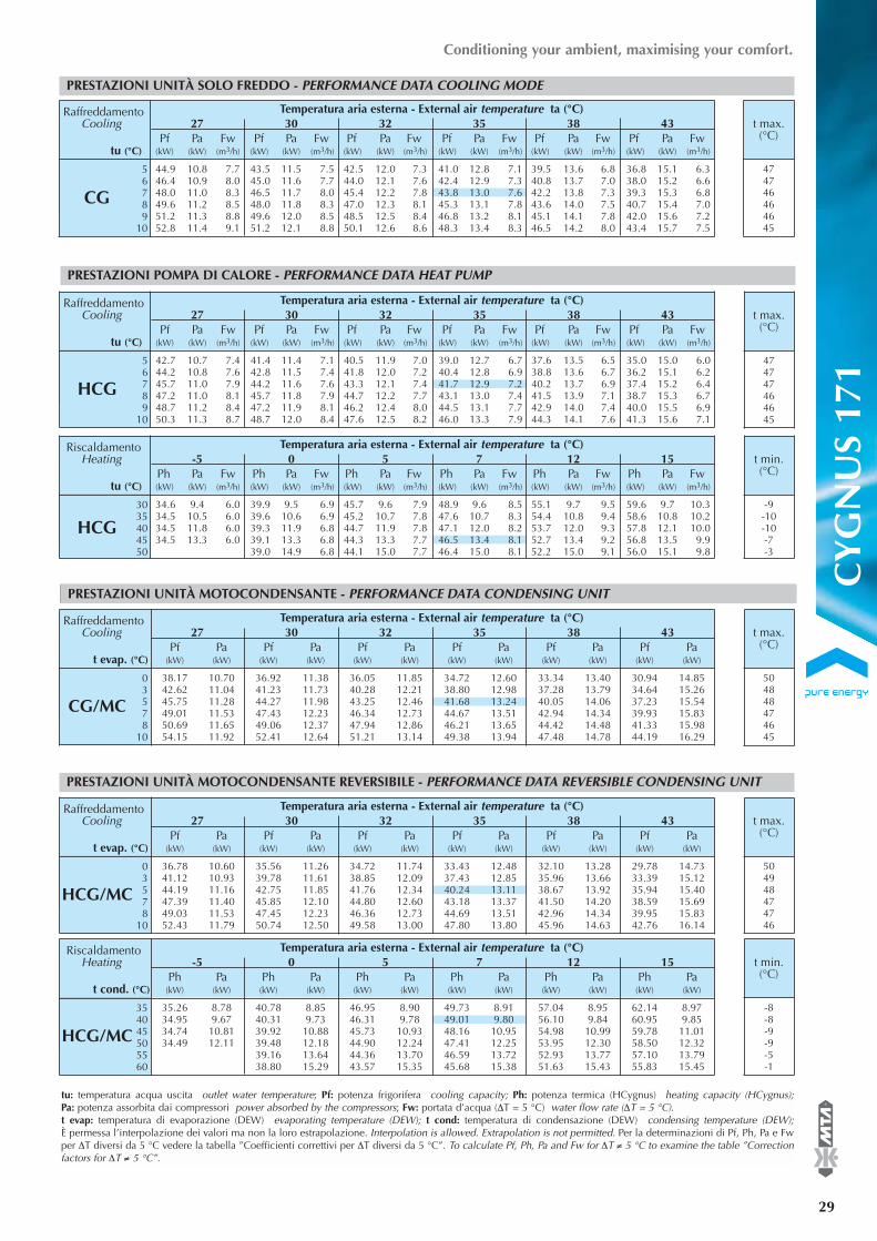
CY
GN
US
171
®
29
Conditioning your ambient, maximising your comfort.
PRESTAZIONI UNITÀ SOLO FREDDO - PERFORMANCE DATA COOLING MODE
56789
10
CG
Raffreddamento Temperatura aria esterna - External air temperature ta (°C)Cooling 27 30 32 35 38 43
Pf Pa Fw Pf Pa Fw Pf Pa Fw Pf Pa Fw Pf Pa Fw Pf Pa Fwtu (°C) (kW) (kW) (m3/h) (kW) (kW) (m3/h) (kW) (kW) (m3/h) (kW) (kW) (m3/h) (kW) (kW) (m3/h) (kW) (kW) (m3/h)
44.9 10.8 7.7 43.5 11.5 7.5 42.5 12.0 7.3 41.0 12.8 7.1 39.5 13.6 6.8 36.8 15.1 6.346.4 10.9 8.0 45.0 11.6 7.7 44.0 12.1 7.6 42.4 12.9 7.3 40.8 13.7 7.0 38.0 15.2 6.648.0 11.0 8.3 46.5 11.7 8.0 45.4 12.2 7.8 43.8 13.0 7.6 42.2 13.8 7.3 39.3 15.3 6.849.6 11.2 8.5 48.0 11.8 8.3 47.0 12.3 8.1 45.3 13.1 7.8 43.6 14.0 7.5 40.7 15.4 7.051.2 11.3 8.8 49.6 12.0 8.5 48.5 12.5 8.4 46.8 13.2 8.1 45.1 14.1 7.8 42.0 15.6 7.252.8 11.4 9.1 51.2 12.1 8.8 50.1 12.6 8.6 48.3 13.4 8.3 46.5 14.2 8.0 43.4 15.7 7.5
t max.(°C)
474746464645
3035404550
HCG
Riscaldamento Temperatura aria esterna - External air temperature ta (°C)Heating -5 0 5 7 12 15
Ph Pa Fw Ph Pa Fw Ph Pa Fw Ph Pa Fw Ph Pa Fw Ph Pa Fwtu (°C) (kW) (kW) (m3/h) (kW) (kW) (m3/h) (kW) (kW) (m3/h) (kW) (kW) (m3/h) (kW) (kW) (m3/h) (kW) (kW) (m3/h)
34.6 9.4 6.0 39.9 9.5 6.9 45.7 9.6 7.9 48.9 9.6 8.5 55.1 9.7 9.5 59.6 9.7 10.334.5 10.5 6.0 39.6 10.6 6.9 45.2 10.7 7.8 47.6 10.7 8.3 54.4 10.8 9.4 58.6 10.8 10.234.5 11.8 6.0 39.3 11.9 6.8 44.7 11.9 7.8 47.1 12.0 8.2 53.7 12.0 9.3 57.8 12.1 10.034.5 13.3 6.0 39.1 13.3 6.8 44.3 13.3 7.7 46.5 13.4 8.1 52.7 13.4 9.2 56.8 13.5 9.9
39.0 14.9 6.8 44.1 15.0 7.7 46.4 15.0 8.1 52.2 15.0 9.1 56.0 15.1 9.8
t min.(°C)
-9-10-10-7-3
56789
10
HCG
Raffreddamento Temperatura aria esterna - External air temperature ta (°C)Cooling 27 30 32 35 38 43
Pf Pa Fw Pf Pa Fw Pf Pa Fw Pf Pa Fw Pf Pa Fw Pf Pa Fwtu (°C) (kW) (kW) (m3/h) (kW) (kW) (m3/h) (kW) (kW) (m3/h) (kW) (kW) (m3/h) (kW) (kW) (m3/h) (kW) (kW) (m3/h)
42.7 10.7 7.4 41.4 11.4 7.1 40.5 11.9 7.0 39.0 12.7 6.7 37.6 13.5 6.5 35.0 15.0 6.044.2 10.8 7.6 42.8 11.5 7.4 41.8 12.0 7.2 40.4 12.8 6.9 38.8 13.6 6.7 36.2 15.1 6.245.7 11.0 7.9 44.2 11.6 7.6 43.3 12.1 7.4 41.7 12.9 7.2 40.2 13.7 6.9 37.4 15.2 6.447.2 11.0 8.1 45.7 11.8 7.9 44.7 12.2 7.7 43.1 13.0 7.4 41.5 13.9 7.1 38.7 15.3 6.748.7 11.2 8.4 47.2 11.9 8.1 46.2 12.4 8.0 44.5 13.1 7.7 42.9 14.0 7.4 40.0 15.5 6.950.3 11.3 8.7 48.7 12.0 8.4 47.6 12.5 8.2 46.0 13.3 7.9 44.3 14.1 7.6 41.3 15.6 7.1
t max.(°C)
474747464645
03578
10
CG/MC
Raffreddamento Temperatura aria esterna - External air temperature ta (°C)Cooling 27 30 32 35 38 43
Pf Pa Pf Pa Pf Pa Pf Pa Pf Pa Pf Pat evap. (°C) (kW) (kW) (kW) (kW) (kW) (kW) (kW) (kW) (kW) (kW) (kW) (kW)
38.17 10.70 36.92 11.38 36.05 11.85 34.72 12.60 33.34 13.40 30.94 14.8542.62 11.04 41.23 11.73 40.28 12.21 38.80 12.98 37.28 13.79 34.64 15.2645.75 11.28 44.27 11.98 43.25 12.46 41.68 13.24 40.05 14.06 37.23 15.5449.01 11.53 47.43 12.23 46.34 12.73 44.67 13.51 42.94 14.34 39.93 15.8350.69 11.65 49.06 12.37 47.94 12.86 46.21 13.65 44.42 14.48 41.33 15.9854.15 11.92 52.41 12.64 51.21 13.14 49.38 13.94 47.48 14.78 44.19 16.29
t max.(°C)
504848474645
tu: temperatura acqua uscita outlet water temperature; Pf: potenza frigorifera cooling capacity; Ph: potenza termica (HCygnus) heating capacity (HCygnus);Pa: potenza assorbita dai compressori power absorbed by the compressors; Fw: portata d’acqua (∆T = 5 °C) water flow rate (∆T = 5 °C).t evap: temperatura di evaporazione (DEW) evaporating temperature (DEW); t cond: temperatura di condensazione (DEW) condensing temperature (DEW);È permessa l’interpolazione dei valori ma non la loro estrapolazione. Interpolation is allowed. Extrapolation is not permitted. Per la determinazioni di Pf, Ph, Pa e Fwper ∆T diversi da 5 °C vedere la tabella ”Coefficienti correttivi per ∆T diversi da 5 °C”. To calculate Pf, Ph, Pa and Fw for ∆T ≠ 5 °C to examine the table ”Correctionfactors for ∆T ≠ 5 °C”.
03578
10
HCG/MC
Raffreddamento Temperatura aria esterna - External air temperature ta (°C)Cooling 27 30 32 35 38 43
Pf Pa Pf Pa Pf Pa Pf Pa Pf Pa Pf Pat evap. (°C) (kW) (kW) (kW) (kW) (kW) (kW) (kW) (kW) (kW) (kW) (kW) (kW)
36.78 10.60 35.56 11.26 34.72 11.74 33.43 12.48 32.10 13.28 29.78 14.7341.12 10.93 39.78 11.61 38.85 12.09 37.43 12.85 35.96 13.66 33.39 15.1244.19 11.16 42.75 11.85 41.76 12.34 40.24 13.11 38.67 13.92 35.94 15.4047.39 11.40 45.85 12.10 44.80 12.60 43.18 13.37 41.50 14.20 38.59 15.6949.03 11.53 47.45 12.23 46.36 12.73 44.69 13.51 42.96 14.34 39.95 15.8352.43 11.79 50.74 12.50 49.58 13.00 47.80 13.80 45.96 14.63 42.76 16.14
t max.(°C)
504948474746
354045505560
HCG/MC
Riscaldamento Temperatura aria esterna - External air temperature ta (°C)Heating -5 0 5 7 12 15
Ph Pa Ph Pa Ph Pa Ph Pa Ph Pa Ph Pat cond. (°C) (kW) (kW) (kW) (kW) (kW) (kW) (kW) (kW) (kW) (kW) (kW) (kW)
35.26 8.78 40.78 8.85 46.95 8.90 49.73 8.91 57.04 8.95 62.14 8.9734.95 9.67 40.31 9.73 46.31 9.78 49.01 9.80 56.10 9.84 60.95 9.8534.74 10.81 39.92 10.88 45.73 10.93 48.16 10.95 54.98 10.99 59.78 11.0134.49 12.11 39.48 12.18 44.90 12.24 47.41 12.25 53.95 12.30 58.50 12.32
39.16 13.64 44.36 13.70 46.59 13.72 52.93 13.77 57.10 13.7938.80 15.29 43.57 15.35 45.68 15.38 51.63 15.43 55.83 15.45
t min.(°C)
-8-8-9-9-5-1
PRESTAZIONI POMPA DI CALORE - PERFORMANCE DATA HEAT PUMP
PRESTAZIONI UNITÀ MOTOCONDENSANTE - PERFORMANCE DATA CONDENSING UNIT
PRESTAZIONI UNITÀ MOTOCONDENSANTE REVERSIBILE - PERFORMANCE DATA REVERSIBLE CONDENSING UNIT

30
®PRESTAZIONI E DATI TECNICI - PERFORMANCE AND TECHNICAL DATA
FLI = potenza massima assorbita nelle condizioni limite di funzionamento max power absorbed in the operating limits condition; FLA = corrente massima assorbita nelle condizioni limite di funzionamento max current absorbed in the operating limits condition; ICF = corrente di spunto alla partenza dell’ultimo compressore nelle condizioni limite di funzionamento start-up current at the start of the last compressor in theoperating limits condition.Per la versione motocondensante (CG/MC) fare riferimento solo alla sezione “Totale senza pompa”. For motocondensing unit (CG/MC) refer only to “Total withoutpump” section.
Totale senza pompa Total without pump Totale con pompa P0 Total with pump P0 Totale con pompa P1 Total with pump P1FLI (kW) FLA (A) ICF (A) FLI (kW) FLA (A) ICF (A) FLI (kW) FLA (A) ICF (A)
21 36 147 22 38 149 23 40 150
ASSORBIMENTI ELETTRICI - ELECTRICAL DATA CG - HCG - CG/MC - HCG/MC
DATI GENERALI - GENERAL DATA CG - HCG - CG/MC - HCG/MC
12
0 - 50 - 100
400±10%/3N/5024±10%/1/50
22
3.84
2234000.700
Compressore CompressorCircuiti frigoriferi Cooling circuits n°Compressori Compressors n°Gradini di parzializzaz. Capacity control %
Alimentazione elettrica Electrical Power supplyPotenza Power V/Ph/HzAusiliari Auxiliaries V/Ph/Hz
Batterie condensanti Condenser CoilsBatterie Coils n°Ranghi Rows n°Superficie frontale Total frontal surface m2
Ventilatori FansVentilatori assiali Axial fans n°Portata aria totale Total coil airflow m3/hPotenza (ciascuno) Power (each) kW
LIVELLI SONORI - SOUND LEVELS CG - HCG - CG/MC - HCG/MC
Bande d’ottava Octave bands (Hz) Potenza Pressione63 125 250 500 1000 2000 4000 8000 Power Pressure
Livello di potenza sonora Sound power level dB(A) dB (A) dB (A)10m
52.3 57.0 63.0 70.0 73.8 73.2 65.9 61.0 78.0 50.0CYGNUSvent. assialiaxial fans
Portata acquaWater flow rate m
3/h 6.02 7.25 8.39 9.42 10.70
Prevalenza disponibile pompa P0 / P1 kPa 137 / 217 121 / 204 105 / 188 88 / 173 66 / 151Available head pressure pump P0 / P1 Prevalenza disponibile pompa P0 / P1 con serbatoio kPa 130 / 211 112 / 194 92 / 176 73 / 157 46 / 131Available head pressure pump P0 / P1 with tankPotenza nominale pompa P0 / P1 kW 0.75 / 1.50Nominal power pump P0 / P1Volume serbatoioTank volume l 150
GRUPPO IDRAULICO - HYDRAULIC GROUP CG
GRUPPO IDRAULICO - HYDRAULIC GROUP HCG
Portata acquaWater flow rate m
3/h 6.03 7.13 8.07 9.27 10.82
Prevalenza disponibile pompa P0 / P1 kPa 142 / 222 129 / 212 118 / 201 101 / 186 77 / 163Available head pressure pump P0 / P1 Prevalenza disponibile pompa P0 / P1 con serbatoio kPa 135 / 215 120 / 203 106 / 190 86 / 171 57 / 142Available head pressure pump P0 / P1 with tankPotenza nominale pompa P0 / P1 kW 0.75 / 1.50Nominal power pump P0 / P1Volume serbatoioTank volume l 150
Evaporatore Evaporator2.9 / 14.2
10Portata min/max evap. Min/max evap. flow rate m3/hVolume d’acqua evap. Evaporator water volume l
* Pesi in esercizio - Weight installedG.I.: Gruppo idraulico; - H.S.: Hydraulic set.
111224701595619642667838
864
647663
688
866
883
571605
Dimensione e peso Dimensions and weight
Profondità Length mmLarghezza Width mmAltezza Heigth mmPeso* CG senza G.I. Weight* without H.G. CG kgPeso* CG solo pompa Weight* CG only pump kgPeso* CG solo doppia pompa Weight* CG only double pump kgPeso* CG con G.I. Weight* with H.G. CG kgPeso* CG con G.I. e doppia pompaWeight* with H.G. CG and double pump
kg
Peso* HCG senza G.I. Weight* without H.G. HCG kgPeso* HCG solo pompa Weight* HCG only pump kgPeso* HCG solo doppia pompa
kgWeight* HCG only double pumpPeso* HCG con G.I. Weight* with H.G. HCG kgPeso* HCG con G.I. e doppia pompaWeight* with H.G. CG and double pump
kg
Peso CG/MC Weight CG/MC kgPeso HCG/MC Weight HCG/MC kg
* Pesi in esercizio - Weight installed.G.I.: Gruppo idraulico; - H.G.: Hydraulic group.
CY
GN
US
211
Potenza sonora: determinata sulla base di misure effettuate in accordo alla normativa ISO 3744. Pressione sonora a 10 m: valore medioricavato in campo libero su piano riflettente ad una distanza di 10 m dal lato esterno quadro elettrico della macchina e a 1.6 m di altezzarispetto alla base di appoggio dell’unità. Valori con tolleranza ± 2 dB. I livelli sonori si riferiscono al funzionamento dell’unità a pieno carico incondizioni nominali e con pompa di circolazione. (1) Per calcolare il livello di pressione sonora ad una distanza diversa impiegare la formula:dB(A)L=dB(A)10m+Kdb.Sound power: determined on the basis of measurements taken in accordance with the standard ISO 3744. Sound pressure at 10 m: Average value obtained in freefield on a reflective surface at a distance of 10 m from the external side of the electrical panel of machine and at a height of 1.6 m from the unit support base. Valueswith tolerance +/- 2 dB. The sound levels refer to operation of the unit under full load in nominal conditions and with circulation pump. (1) Tocalculate a different distance of the sound pressure level, use the formula: dB(A)L=dB(A)10m+Kdb.
Distanza (1)Distance
L (m) Kdb1 153 105 610 0

CY
GN
US
211
®
31
Conditioning your ambient, maximising your comfort.
PRESTAZIONI UNITÀ SOLO FREDDO - PERFORMANCE DATA COOLING MODE
56789
10
CG
Raffreddamento Temperatura aria esterna - External air temperature ta (°C)Cooling 27 30 32 35 38 43
Pf Pa Fw Pf Pa Fw Pf Pa Fw Pf Pa Fw Pf Pa Fw Pf Pa Fwtu (°C) (kW) (kW) (m3/h) (kW) (kW) (m3/h) (kW) (kW) (m3/h) (kW) (kW) (m3/h) (kW) (kW) (m3/h) (kW) (kW) (m3/h)
50.9 12.8 8.8 49.4 13.6 8.5 48.3 14.2 8.3 46.7 15.1 8.0 44.9 16.1 7.7 42.0 17.9 7.252.6 12.9 9.1 51.0 13.8 8.8 49.9 14.3 8.6 48.2 15.3 8.3 46.5 16.3 8.0 43.4 18.1 7.554.4 13.0 9.4 52.7 13.9 9.1 51.6 14.5 8.9 49.8 15.4 8.6 48.0 16.4 8.3 44.9 18.2 7.756.1 13.2 9.7 54.4 14.0 9.4 53.3 14.6 9.2 51.5 15.5 8.9 49.6 16.6 8.5 46.3 18.4 8.058.0 13.3 10.0 56.2 14.1 9.7 55.0 14.7 9.5 53.1 15.7 9.2 51.2 16.7 8.8 47.9 18.5 8.259.8 13.4 10.3 58.0 14.3 10.0 56.7 14.9 9.8 54.8 15.8 9.4 52.8 16.8 9.1 49.4 18.7 8.5
t max.(°C)
464646454544
3035404550
HCG
Riscaldamento Temperatura aria esterna - External air temperature ta (°C)Heating -5 0 5 7 12 15
Ph Pa Fw Ph Pa Fw Ph Pa Fw Ph Pa Fw Ph Pa Fw Ph Pa Fwtu (°C) (kW) (kW) (m3/h) (kW) (kW) (m3/h) (kW) (kW) (m3/h) (kW) (kW) (m3/h) (kW) (kW) (m3/h) (kW) (kW) (m3/h)
40.5 10.9 7.0 46.8 11.0 8.1 53.9 11.0 9.3 56.6 11.0 9.8 64.8 11.1 11.2 70.3 11.1 12.240.4 12.2 7.0 46.4 12.3 8.0 53.4 12.3 9.3 56.0 12.3 9.7 63.8 12.4 11.0 69.3 12.4 12.040.4 13.7 7.0 46.2 13.7 8.0 52.8 13.8 9.2 55.5 13.8 9.6 63.1 13.8 11.0 68.2 13.8 11.840.5 15.5 7.0 46.0 15.5 8.0 52.0 15.5 9.0 54.8 15.5 9.5 62.2 15.5 10.8 67.0 15.5 11.6
45.9 17.4 8.0 51.8 17.4 9.0 54.4 17.4 9.5 61.3 17.4 10.7 66.0 17.4 11.5
t min.(°C)
-10-10-10-7-3
56789
10
HCG
Raffreddamento Temperatura aria esterna - External air temperature ta (°C)Cooling 27 30 32 35 38 43
Pf Pa Fw Pf Pa Fw Pf Pa Fw Pf Pa Fw Pf Pa Fw Pf Pa Fwtu (°C) (kW) (kW) (m3/h) (kW) (kW) (m3/h) (kW) (kW) (m3/h) (kW) (kW) (m3/h) (kW) (kW) (m3/h) (kW) (kW) (m3/h)
49.3 12.3 8.5 47.8 13.1 8.2 46.8 13.6 8.1 45.3 14.5 7.8 43.6 15.5 7.5 40.9 17.2 7.051.0 12.4 8.8 49.5 13.2 8.5 48.4 13.7 8.3 46.8 14.6 8.1 45.2 15.6 7.8 42.2 17.4 7.352.7 12.5 9.1 51.1 13.3 8.8 50.0 13.9 8.6 48.4 14.8 8.3 46.7 15.7 8.0 43.7 17.5 7.554.4 12.6 9.4 52.8 13.4 9.1 51.7 14.0 8.9 50.0 14.9 8.6 48.2 15.9 8.3 45.1 17.6 7.856.2 12.7 9.7 54.5 13.5 9.4 53.4 14.1 9.2 51.6 15.0 8.9 49.8 16.0 8.6 46.6 17.8 8.058.0 12.8 10.0 56.3 13.6 9.7 55.1 14.2 9.5 53.3 15.1 9.2 51.4 16.1 8.9 48.2 17.9 8.3
t max.(°C)
474747464645
03578
10
CG/MC
Raffreddamento Temperatura aria esterna - External air temperature ta (°C)Cooling 27 30 32 35 38 43
Pf Pa Pf Pa Pf Pa Pf Pa Pf Pa Pf Pat evap. (°C) (kW) (kW) (kW) (kW) (kW) (kW) (kW) (kW) (kW) (kW) (kW) (kW)
43.54 12.66 42.15 13.47 41.20 14.05 39.72 14.96 38.19 15.94 35.51 17.7148.52 13.05 46.99 13.88 45.93 14.47 44.30 15.39 42.61 16.38 39.67 18.1752.02 13.32 50.38 14.16 49.25 14.75 47.51 15.69 45.72 16.69 42.58 18.4955.65 13.60 53.91 14.45 52.71 15.05 50.86 16.00 48.95 17.00 45.62 18.8157.53 13.74 55.73 14.60 54.49 15.20 52.58 16.15 50.61 17.16 47.18 18.9861.38 14.04 59.46 14.91 58.15 15.51 56.12 16.47 54.03 17.49 50.39 19.32
t max.(°C)
494847464644
tu: temperatura acqua uscita outlet water temperature; Pf: potenza frigorifera cooling capacity; Ph: potenza termica (HCygnus) heating capacity (HCygnus);Pa: potenza assorbita dai compressori power absorbed by the compressors; Fw: portata d’acqua (∆T = 5 °C) water flow rate (∆T = 5 °C).t evap: temperatura di evaporazione (DEW) evaporating temperature (DEW); t cond: temperatura di condensazione (DEW) condensing temperature (DEW);È permessa l’interpolazione dei valori ma non la loro estrapolazione. Interpolation is allowed. Extrapolation is not permitted. Per la determinazioni di Pf, Ph, Pa e Fwper ∆T diversi da 5 °C vedere la tabella ”Coefficienti correttivi per ∆T diversi da 5 °C”. To calculate Pf, Ph, Pa and Fw for ∆T ≠ 5 °C to examine the table ”Correctionfactors for ∆T ≠ 5 °C”.
03578
10
HCG/MC
Raffreddamento Temperatura aria esterna - External air temperature ta (°C)Cooling 27 30 32 35 38 43
Pf Pa Pf Pa Pf Pa Pf Pa Pf Pa Pf Pat evap. (°C) (kW) (kW) (kW) (kW) (kW) (kW) (kW) (kW) (kW) (kW) (kW) (kW)
41.98 12.53 40.63 13.35 39.71 13.92 38.27 14.83 36.79 15.80 34.20 17.5646.85 12.92 45.36 13.74 44.34 14.33 42.76 15.25 41.12 16.23 38.27 18.0250.27 13.18 48.69 14.02 47.60 14.61 45.91 15.54 44.17 16.53 41.13 18.3353.84 13.46 52.15 14.31 50.99 14.90 49.19 15.84 47.34 16.85 44.11 18.6555.68 13.60 53.93 14.45 52.73 15.05 50.88 16.00 48.97 17.00 45.64 18.8259.46 13.89 57.60 14.75 56.33 15.36 54.36 16.31 52.32 17.33 48.79 19.15
t max.(°C)
494847464645
354045505560
HCG/MC
Riscaldamento Temperatura aria esterna - External air temperature ta (°C)Heating -5 0 5 7 12 15
Ph Pa Ph Pa Ph Pa Ph Pa Ph Pa Ph Pat cond. (°C) (kW) (kW) (kW) (kW) (kW) (kW) (kW) (kW) (kW) (kW) (kW) (kW)
40.87 10.11 47.45 10.17 54.77 10.20 57.89 10.21 66.44 10.21 72.28 10.2040.66 11.15 47.17 11.20 54.08 11.23 57.09 11.23 65.59 11.23 71.12 11.2240.42 12.50 46.66 12.54 53.47 12.57 56.35 12.57 64.29 12.57 69.74 12.5540.45 14.03 46.25 14.07 52.77 14.09 55.52 14.09 63.10 14.08 68.23 14.0640.30 15.76 45.98 15.80 51.99 15.81 54.60 15.81 61.87 15.79 66.86 15.76
45.67 17.74 51.35 17.75 53.81 17.74 60.62 17.71 65.37 17.68
t min.(°C)
-8-9-10-10-6-1
PRESTAZIONI POMPA DI CALORE - PERFORMANCE DATA HEAT PUMP
PRESTAZIONI UNITÀ MOTOCONDENSANTE - PERFORMANCE DATA CONDENSING UNIT
PRESTAZIONI UNITÀ MOTOCONDENSANTE REVERSIBILE - PERFORMANCE DATA REVERSIBLE CONDENSING UNIT

32
®PRESTAZIONI E DATI TECNICI - PERFORMANCE AND TECHNICAL DATA
DATI GENERALI - GENERAL DATA CG - HCG - CG/MC - HCG/MC
12
0 - 50 - 100
400±10%/3N/5024±10%/1/50
23
3.84
2228000.700
Compressore CompressorCircuiti frigoriferi Cooling circuits n°Compressori Compressors n°Gradini di parzializzaz. Capacity control %
Alimentazione elettrica Electrical Power supplyPotenza Power V/Ph/HzAusiliari Auxiliaries V/Ph/Hz
Batterie condensanti Condenser CoilsBatterie Coils n°Ranghi Rows n°Superficie frontale Total frontal surface m2
Ventilatori FansVentilatori assiali Axial fans n°Portata aria totale Total coil airflow m3/hPotenza (ciascuno) Power (each) kW
FLI = potenza massima assorbita nelle condizioni limite di funzionamento max power absorbed in the operating limits condition; FLA = corrente massima assorbita nelle condizioni limite di funzionamento max current absorbed in the operating limits condition; ICF = corrente di spunto alla partenza dell’ultimo compressore nelle condizioni limite di funzionamento start-up current at the start of the last compressor in theoperating limits condition.Per la versione motocondensante (CG/MC) fare riferimento solo alla sezione “Totale senza pompa”. For motocondensing unit (CG/MC) refer only to “Total withoutpump” section.
Totale senza pompa Total without pump Totale con pompa P0 Total with pump P0 Totale con pompa P1 Total with pump P1FLI (kW) FLA (A) ICF (A) FLI (kW) FLA (A) ICF (A) FLI (kW) FLA (A) ICF (A)
25 42 140 26 44 142 26 45 143
ASSORBIMENTI ELETTRICI - ELECTRICAL DATA CG - HCG - CG/MC - HCG/MC
LIVELLI SONORI - SOUND LEVELS CG - HCG - CG/MC - HCG/MC
Bande d’ottava Octave bands (Hz) Potenza Pressione63 125 250 500 1000 2000 4000 8000 Power Pressure
Livello di potenza sonora Sound power level dB(A) dB (A) dB (A)10m
52.3 57.1 63.0 70.1 74.1 74.4 67.7 61.7 78.7 50.7CYGNUSvent. assialiaxial fans
Portata acquaWater flow rate m
3/h 6.65 7.53 8.46 9.82 11.06
Prevalenza disponibile pompa P0 / P1 kPa 134 / 216 123 / 206 111 / 195 92 / 176 72 / 157Available head pressure pump P0 / P1 Prevalenza disponibile pompa P0 / P1 con serbatoio kPa 126 / 208 113 / 196 99 / 183 75 / 159 50 / 135Available head pressure pump P0 / P1 with tankPotenza nominale pompa P0 / P1 kW 0.75 / 1.50Nominal power pump P0 / P1Volume serbatoioTank volume l 150
GRUPPO IDRAULICO - HYDRAULIC GROUP CG
GRUPPO IDRAULICO - HYDRAULIC GROUP HCG
Portata acquaWater flow rate m
3/h 6.62 7.39 8.14 9.46 10.64
Prevalenza disponibile pompa P0 / P1 kPa 138 / 220 130 / 212 121 / 205 104 / 189 87 / 172Available head pressure pump P0 / P1 Prevalenza disponibile pompa P0 / P1 con serbatoio kPa 130 / 212 120 / 203 109 / 193 88 / 173 67 / 152Available head pressure pump P0 / P1 with tankPotenza nominale pompa P0 / P1 kW 0.75 / 1.50Nominal power pump P0 / P1Volume serbatoioTank volume l 150
Evaporatore Evaporator3.2 / 16.5
10Portata min/max evap. Min/max evap. flow rate m3/hVolume d’acqua evap. Evaporator water volume l
* Pesi in esercizio - Weight installedG.I.: Gruppo idraulico; - H.S.: Hydraulic set.
111224701595644668694863
889
672693
719
891
915
593630
Dimensione e peso Dimensions and weight
Profondità Length mmLarghezza Width mmAltezza Heigth mmPeso* CG senza G.I. Weight* without H.G. CG kgPeso* CG solo pompa Weight* CG only pump kgPeso* CG solo doppia pompa Weight* CG only double pump kgPeso* CG con G.I. Weight* with H.G. CG kgPeso* CG con G.I. e doppia pompaWeight* with H.G. CG and double pump
kg
Peso* HCG senza G.I. Weight* without H.G. HCG kgPeso* HCG solo pompa Weight* HCG only pump kgPeso* HCG solo doppia pompa
kgWeight* HCG only double pumpPeso* HCG con G.I. Weight* with H.G. HCG kgPeso* HCG con G.I. e doppia pompaWeight* with H.G. CG and double pump
kg
Peso CG/MC Weight CG/MC kgPeso HCG/MC Weight HCG/MC kg
* Pesi in esercizio - Weight installed.G.I.: Gruppo idraulico; - H.G.: Hydraulic group.
CY
GN
US
251
Potenza sonora: determinata sulla base di misure effettuate in accordo alla normativa ISO 3744. Pressione sonora a 10 m: valore medioricavato in campo libero su piano riflettente ad una distanza di 10 m dal lato esterno quadro elettrico della macchina e a 1.6 m di altezzarispetto alla base di appoggio dell’unità. Valori con tolleranza ± 2 dB. I livelli sonori si riferiscono al funzionamento dell’unità a pieno carico incondizioni nominali e con pompa di circolazione. (1) Per calcolare il livello di pressione sonora ad una distanza diversa impiegare la formula:dB(A)L=dB(A)10m+Kdb.Sound power: determined on the basis of measurements taken in accordance with the standard ISO 3744. Sound pressure at 10 m: Average value obtained in freefield on a reflective surface at a distance of 10 m from the external side of the electrical panel of machine and at a height of 1.6 m from the unit support base. Valueswith tolerance +/- 2 dB. The sound levels refer to operation of the unit under full load in nominal conditions and with circulation pump. (1) Tocalculate a different distance of the sound pressure level, use the formula: dB(A)L=dB(A)10m+Kdb.
Distanza (1)Distance
L (m) Kdb1 153 105 610 0

CY
GN
US
251
®
33
Conditioning your ambient, maximising your comfort.
PRESTAZIONI UNITÀ SOLO FREDDO - PERFORMANCE DATA COOLING MODE
56789
10
CG
Raffreddamento Temperatura aria esterna - External air temperature ta (°C)Cooling 27 30 32 35 38 43
Pf Pa Fw Pf Pa Fw Pf Pa Fw Pf Pa Fw Pf Pa Fw Pf Pa Fwtu (°C) (kW) (kW) (m3/h) (kW) (kW) (m3/h) (kW) (kW) (m3/h) (kW) (kW) (m3/h) (kW) (kW) (m3/h) (kW) (kW) (m3/h)
58.4 14.1 10.1 56.5 15.0 9.7 55.3 15.7 9.5 53.3 16.7 9.2 51.2 17.9 8.8 47.6 20.0 8.260.4 14.2 10.4 58.5 15.1 10.1 57.2 15.8 9.8 55.1 16.9 9.5 53.0 18.0 9.1 49.2 20.2 8.562.5 14.3 10.8 60.5 15.3 10.4 59.1 15.9 10.2 57.0 17.0 9.8 54.8 18.2 9.4 51.0 20.3 8.864.6 14.4 11.1 62.5 15.4 10.8 61.1 16.1 10.5 59.0 17.2 10.2 56.7 18.3 9.8 52.7 20.5 9.166.7 14.6 11.5 64.6 15.5 11.1 63.2 16.2 10.9 60.9 17.3 10.5 58.6 18.5 10.1 54.5 20.7 9.468.9 14.7 11.9 66.7 15.7 11.5 65.2 16.4 11.2 62.9 17.5 10.8 60.5 18.6 10.4 56.3 20.8 9.7
t max.(°C)
464646454544
3035404550
HCG
Riscaldamento Temperatura aria esterna - External air temperature ta (°C)Heating -5 0 5 7 12 15
Ph Pa Fw Ph Pa Fw Ph Pa Fw Ph Pa Fw Ph Pa Fw Ph Pa Fwtu (°C) (kW) (kW) (m3/h) (kW) (kW) (m3/h) (kW) (kW) (m3/h) (kW) (kW) (m3/h) (kW) (kW) (m3/h) (kW) (kW) (m3/h)
45.2 12.5 7.8 52.0 12.5 9.0 59.6 12.6 10.3 62.9 12.6 10.9 71.9 12.7 12.4 77.8 12.7 13.545.2 14.1 7.8 51.7 14.1 9.0 59.0 14.1 10.2 62.2 14.1 10.8 71.0 14.2 12.3 76.6 14.2 13.344.9 15.9 7.8 51.4 15.9 8.9 58.5 15.9 10.1 61.5 15.9 10.7 69.9 15.9 12.1 75.6 15.9 13.145.1 18.0 7.8 51.2 18.0 8.9 58.0 17.9 10.1 60.9 17.9 10.6 69.1 17.9 12.0 74.3 17.9 12.9
51.2 20.5 8.9 57.6 20.4 10.0 60.4 20.3 10.5 68.1 20.2 11.9 73.1 20.2 12.7
t min.(°C)
-10-10-10-7-2
56789
10
HCG
Raffreddamento Temperatura aria esterna - External air temperature ta (°C)Cooling 27 30 32 35 38 43
Pf Pa Fw Pf Pa Fw Pf Pa Fw Pf Pa Fw Pf Pa Fw Pf Pa Fwtu (°C) (kW) (kW) (m3/h) (kW) (kW) (m3/h) (kW) (kW) (m3/h) (kW) (kW) (m3/h) (kW) (kW) (m3/h) (kW) (kW) (m3/h)
55.5 14.0 9.6 53.8 14.9 9.3 52.5 15.6 9.0 50.6 16.7 8.7 48.6 17.8 8.4 45.1 20.0 7.857.5 14.1 9.9 55.6 15.1 9.6 54.4 15.7 9.4 52.4 16.8 9.0 50.4 18.0 8.7 46.7 20.1 8.059.4 14.2 10.2 57.5 15.2 9.9 56.2 15.9 9.7 54.2 17.0 9.3 52.1 18.1 9.0 48.4 20.3 8.361.4 14.4 10.6 59.5 15.3 10.2 58.1 16.0 10.0 56.0 17.1 9.6 53.9 18.3 9.3 50.0 20.4 8.663.4 14.5 10.9 61.4 15.4 10.6 60.0 16.1 10.3 57.9 17.2 10.0 55.7 18.4 9.6 51.7 20.6 8.965.5 14.6 11.3 63.4 15.6 10.9 62.0 16.3 10.7 59.8 17.4 10.3 57.5 18.6 9.9 53.4 20.7 9.2
t max.(°C)
464646454545
03578
10
CG/MC
Raffreddamento Temperatura aria esterna - External air temperature ta (°C)Cooling 27 30 32 35 38 43
Pf Pa Pf Pa Pf Pa Pf Pa Pf Pa Pf Pat evap. (°C) (kW) (kW) (kW) (kW) (kW) (kW) (kW) (kW) (kW) (kW) (kW) (kW)
49.87 13.93 48.19 14.86 47.03 15.52 45.23 16.57 43.35 17.70 40.05 19.8055.75 14.33 53.90 15.28 52.62 15.95 50.64 17.02 48.58 18.17 44.96 20.2959.88 14.61 57.91 15.57 56.55 16.25 54.44 17.33 52.25 18.49 48.40 20.6364.19 14.90 62.09 15.87 60.65 16.56 58.40 17.65 56.07 18.83 51.99 20.9866.41 15.05 64.25 16.03 62.75 16.72 60.44 17.82 58.04 19.00 53.83 21.1670.98 15.36 68.68 16.35 67.09 17.05 64.63 18.16 62.09 19.36 57.63 21.53
t max.(°C)
494847464645
tu: temperatura acqua uscita outlet water temperature; Pf: potenza frigorifera cooling capacity; Ph: potenza termica (HCygnus) heating capacity (HCygnus);Pa: potenza assorbita dai compressori power absorbed by the compressors; Fw: portata d’acqua (∆T = 5 °C) water flow rate (∆T = 5 °C).t evap: temperatura di evaporazione (DEW) evaporating temperature (DEW); t cond: temperatura di condensazione (DEW) condensing temperature (DEW);È permessa l’interpolazione dei valori ma non la loro estrapolazione. Interpolation is allowed. Extrapolation is not permitted. Per la determinazioni di Pf, Ph, Pa e Fwper ∆T diversi da 5 °C vedere la tabella ”Coefficienti correttivi per ∆T diversi da 5 °C”. To calculate Pf, Ph, Pa and Fw for ∆T ≠ 5 °C to examine the table ”Correctionfactors for ∆T ≠ 5 °C”.
03578
10
HCG/MC
Raffreddamento Temperatura aria esterna - External air temperature ta (°C)Cooling 27 30 32 35 38 43
Pf Pa Pf Pa Pf Pa Pf Pa Pf Pa Pf Pat evap. (°C) (kW) (kW) (kW) (kW) (kW) (kW) (kW) (kW) (kW) (kW) (kW) (kW)
48.02 13.81 46.39 14.73 45.27 15.38 43.53 16.43 41.71 17.56 38.50 19.6453.77 14.20 51.98 15.13 50.74 15.80 48.82 16.87 46.82 18.01 43.31 20.1257.82 14.47 55.91 15.42 54.59 16.10 52.55 17.17 50.42 18.33 46.68 20.4662.04 14.76 60.01 15.72 58.61 16.40 56.43 17.49 54.17 18.66 50.20 20.8064.22 14.90 62.12 15.87 60.67 16.56 58.43 17.66 56.10 18.83 52.01 20.9868.71 15.20 66.47 16.19 64.93 16.88 62.55 17.99 60.07 19.18 55.74 21.35
t max.(°C)
494847464645
354045505560
HCG/MC
Riscaldamento Temperatura aria esterna - External air temperature ta (°C)Heating -5 0 5 7 12 15
Ph Pa Ph Pa Ph Pa Ph Pa Ph Pa Ph Pat cond. (°C) (kW) (kW) (kW) (kW) (kW) (kW) (kW) (kW) (kW) (kW) (kW) (kW)
45.56 11.60 52.77 11.63 60.86 11.65 64.40 11.66 73.99 11.65 80.43 11.6445.32 12.79 52.33 12.82 60.19 12.83 63.64 12.84 72.94 12.83 79.26 12.8144.92 14.38 51.86 14.40 59.23 14.41 62.55 14.41 71.47 14.38 77.70 14.3644.70 16.22 51.37 16.23 58.44 16.23 61.62 16.22 70.16 16.19 76.06 16.1644.68 18.33 50.88 18.33 57.63 18.32 60.66 18.31 68.81 18.26 74.60 18.22
50.62 20.74 57.02 20.71 59.66 20.69 67.55 20.64 72.81 20.59
t min.(°C)
-8-9-10-10-6-1
PRESTAZIONI POMPA DI CALORE - PERFORMANCE DATA HEAT PUMP
PRESTAZIONI UNITÀ MOTOCONDENSANTE - PERFORMANCE DATA CONDENSING UNIT
PRESTAZIONI UNITÀ MOTOCONDENSANTE REVERSIBILE - PERFORMANCE DATA REVERSIBLE CONDENSING UNIT

34
®PRESTAZIONI E DATI TECNICI - PERFORMANCE AND TECHNICAL DATA
FLI = potenza massima assorbita nelle condizioni limite di funzionamento max power absorbed in the operating limits condition; FLA = corrente massima assorbita nelle condizioni limite di funzionamento max current absorbed in the operating limits condition; ICF = corrente di spunto alla partenza dell’ultimo compressore nelle condizioni limite di funzionamento start-up current at the start of the last compressor in theoperating limits condition.Per la versione motocondensante (CG/MC) fare riferimento solo alla sezione “Totale senza pompa”. For motocondensing unit (CG/MC) refer only to “Total withoutpump” section.
Totale senza pompa Total without pump Totale con pompa P0 Total with pump P0 Totale con pompa P1 Total with pump P1FLI (kW) FLA (A) ICF (A) FLI (kW) FLA (A) ICF (A) FLI (kW) FLA (A) ICF (A)
28 46 144 29 48 146 29 50 148
ASSORBIMENTI ELETTRICI - ELECTRICAL DATA CG - HCG - CG/MC - HCG/MC
DATI GENERALI - GENERAL DATA CG - HCG - CG/MC - HCG/MC
12
0 - 50 -100
400±10%/3N/5024±10%/1/50
23
3.84
2228000.700
Compressore CompressorCircuiti frigoriferi Cooling circuits n°Compressori Compressors n°Gradini di parzializzaz. Capacity control %
Alimentazione elettrica Electrical Power supplyPotenza Power V/Ph/HzAusiliari Auxiliaries V/Ph/Hz
Batterie condensanti Condenser CoilsBatterie Coils n°Ranghi Rows n°Superficie frontale Total frontal surface m2
Ventilatori FansVentilatori assiali Axial fans n°Portata aria totale Total coil airflow m3/hPotenza (ciascuno) Power (each) kW
LIVELLI SONORI - SOUND LEVELS CG - HCG - CG/MC - HCG/MC
Bande d’ottava Octave bands (Hz) Potenza Pressione63 125 250 500 1000 2000 4000 8000 Power Pressure
Livello di potenza sonora Sound power level dB(A) dB (A) dB (A)10m
52.3 56.5 62.4 71.9 73.9 74.6 70.0 66.5 79.3 51.3CYGNUSvent. assialiaxial fans
Portata acquaWater flow rate m
3/h 7.78 8.50 9.53 10.79 12.09
Prevalenza disponibile pompa P0 / P1 kPa 137 / 218 127 / 209 112 / 196 92 / 177 69 / 155Available head pressure pump P0 / P1 Prevalenza disponibile pompa P0 / P1 con serbatoio kPa 125 / 207 113 / 196 94 / 179 69 / 155 40 / 128Available head pressure pump P0 / P1 with tankPotenza nominale pompa P0 / P1 kW 0.75 / 1.50Nominal power pump P0 / P1Volume serbatoioTank volume l 150
GRUPPO IDRAULICO - HYDRAULIC GROUP CG
GRUPPO IDRAULICO - HYDRAULIC GROUP HCG
Portata acquaWater flow rate m
3/h 7.73 8.63 9.33 10.82 12.48
Prevalenza disponibile pompa P0 / P1 kPa 141 / 219 129 / 209 118 / 200 95 / 178 65 / 150Available head pressure pump P0 / P1 Prevalenza disponibile pompa P0 / P1 con serbatoio kPa 129 / 208 114 / 195 101 / 184 71 / 156 34 / 121Available head pressure pump P0 / P1 with tankPotenza nominale pompa P0 / P1 kW 0.75 / 1.50Nominal power pump P0 / P1Volume serbatoioTank volume l 150
Evaporatore Evaporator3.7 / 18.3
10Portata min/max evap. Min/max evap. flow rate m3/hVolume d’acqua evap. Evaporator water volume l
* Pesi in esercizio - Weight installedG.I.: Gruppo idraulico; - H.S.: Hydraulic set.
111224701595661685711880
906
689715
741
908
932
608645
Dimensione e peso Dimensions and weight
Profondità Length mmLarghezza Width mmAltezza Heigth mmPeso* CG senza G.I. Weight* without H.G. CG kgPeso* CG solo pompa Weight* CG only pump kgPeso* CG solo doppia pompa Weight* CG only double pump kgPeso* CG con G.I. Weight* with H.G. CG kgPeso* CG con G.I. e doppia pompaWeight* with H.G. CG and double pump
kg
Peso* HCG senza G.I. Weight* without H.G. HCG kgPeso* HCG solo pompa Weight* HCG only pump kgPeso* HCG solo doppia pompa
kgWeight* HCG only double pumpPeso* HCG con G.I. Weight* with H.G. HCG kgPeso* HCG con G.I. e doppia pompaWeight* with H.G. CG and double pump
kg
Peso CG/MC Weight CG/MC kgPeso HCG/MC Weight HCG/MC kg
* Pesi in esercizio - Weight installed.G.I.: Gruppo idraulico; - H.G.: Hydraulic group.
CY
GN
US
301
Potenza sonora: determinata sulla base di misure effettuate in accordo alla normativa ISO 3744. Pressione sonora a 10 m: valore medioricavato in campo libero su piano riflettente ad una distanza di 10 m dal lato esterno quadro elettrico della macchina e a 1.6 m di altezzarispetto alla base di appoggio dell’unità. Valori con tolleranza ± 2 dB. I livelli sonori si riferiscono al funzionamento dell’unità a pieno carico incondizioni nominali e con pompa di circolazione. (1) Per calcolare il livello di pressione sonora ad una distanza diversa impiegare la formula:dB(A)L=dB(A)10m+Kdb.Sound power: determined on the basis of measurements taken in accordance with the standard ISO 3744. Sound pressure at 10 m: Average value obtained in freefield on a reflective surface at a distance of 10 m from the external side of the electrical panel of machine and at a height of 1.6 m from the unit support base. Valueswith tolerance +/- 2 dB. The sound levels refer to operation of the unit under full load in nominal conditions and with circulation pump. (1) Tocalculate a different distance of the sound pressure level, use the formula: dB(A)L=dB(A)10m+Kdb.
Distanza (1)Distance
L (m) Kdb1 153 105 610 0

CY
GN
US
301
®
35
Conditioning your ambient, maximising your comfort.
PRESTAZIONI UNITÀ SOLO FREDDO - PERFORMANCE DATA COOLING MODE
56789
10
CG
Raffreddamento Temperatura aria esterna - External air temperature ta (°C)Cooling 27 30 32 35 38 43
Pf Pa Fw Pf Pa Fw Pf Pa Fw Pf Pa Fw Pf Pa Fw Pf Pa Fwtu (°C) (kW) (kW) (m3/h) (kW) (kW) (m3/h) (kW) (kW) (m3/h) (kW) (kW) (m3/h) (kW) (kW) (m3/h) (kW) (kW) (m3/h)
66.9 17.2 11.5 64.9 18.2 11.2 63.5 19.0 10.9 61.3 20.2 10.6 59.1 21.5 10.2 55.1 23.9 9.569.1 17.3 11.9 67.1 18.4 11.5 65.6 19.2 11.3 63.4 20.4 10.9 61.1 21.7 10.5 57.0 24.1 9.871.4 17.5 12.3 69.3 18.6 11.9 67.8 19.4 11.7 65.5 20.6 11.3 63.1 21.9 10.9 58.9 24.3 10.173.7 17.7 12.7 71.5 18.8 12.3 70.0 19.6 12.1 67.6 20.8 11.6 65.1 22.1 11.2 60.8 24.5 10.576.1 17.9 13.1 73.8 19.0 12.7 72.2 19.8 12.4 69.8 21.0 12.0 67.2 22.3 11.6 62.8 24.7 10.878.5 18.1 13.5 76.1 19.2 13.1 74.5 20.0 12.8 72.0 21.2 12.4 69.4 22.6 12.0 64.8 25.0 11.2
t max.(°C)
464545454444
3035404550
HCG
Riscaldamento Temperatura aria esterna - External air temperature ta (°C)Heating -5 0 5 7 12 15
Ph Pa Fw Ph Pa Fw Ph Pa Fw Ph Pa Fw Ph Pa Fw Ph Pa Fwtu (°C) (kW) (kW) (m3/h) (kW) (kW) (m3/h) (kW) (kW) (m3/h) (kW) (kW) (m3/h) (kW) (kW) (m3/h) (kW) (kW) (m3/h)
52.4 14.5 9.1 60.0 14.6 10.4 68.3 14.7 11.8 72.0 14.8 12.5 81.9 14.8 14.2 87.7 14.9 15.252.2 16.2 9.1 59.9 16.3 10.4 67.9 16.4 11.8 71.3 16.4 12.4 81.1 16.5 14.1 87.1 16.6 15.152.4 18.2 9.1 59.6 18.3 10.3 67.5 18.3 11.7 71.0 18.4 12.3 80.4 18.4 14.0 86.5 18.5 15.052.7 20.5 9.2 59.5 20.5 10.3 67.1 20.6 11.7 70.4 20.6 12.2 79.5 20.6 13.8 85.4 20.7 14.8
59.7 23.2 10.4 66.8 23.1 11.6 70.1 23.1 12.2 78.6 23.1 13.7 84.4 23.1 14.7
t min.(°C)
-9-9-9-6-1
56789
10
HCG
Raffreddamento Temperatura aria esterna - External air temperature ta (°C)Cooling 27 30 32 35 38 43
Pf Pa Fw Pf Pa Fw Pf Pa Fw Pf Pa Fw Pf Pa Fw Pf Pa Fwtu (°C) (kW) (kW) (m3/h) (kW) (kW) (m3/h) (kW) (kW) (m3/h) (kW) (kW) (m3/h) (kW) (kW) (m3/h) (kW) (kW) (m3/h)
63.2 17.0 10.9 61.3 18.1 10.6 60.0 18.9 10.3 58.0 20.1 10.0 55.9 21.4 9.6 52.1 23.8 9.065.3 17.2 11.2 63.4 18.3 10.9 62.0 19.1 10.7 59.9 20.3 10.3 57.8 21.6 9.9 53.9 24.0 9.367.5 17.4 11.6 65.5 18.5 11.3 64.1 19.3 11.0 61.9 20.5 10.7 59.7 21.8 10.3 55.7 24.2 9.669.7 17.6 12.0 67.6 18.7 11.6 66.2 19.4 11.4 63.9 20.7 11.0 61.6 22.0 10.6 57.5 24.4 9.971.9 17.7 12.4 69.8 18.9 12.0 68.3 19.6 11.8 66.0 20.9 11.4 63.6 22.2 11.0 59.4 24.6 10.274.2 17.9 12.8 71.9 19.0 12.4 70.4 19.8 12.1 68.1 21.1 11.7 65.6 22.4 11.3 61.3 24.8 10.6
t max.(°C)
464645454444
03578
10
CG/MC
Raffreddamento Temperatura aria esterna - External air temperature ta (°C)Cooling 27 30 32 35 38 43
Pf Pa Pf Pa Pf Pa Pf Pa Pf Pa Pf Pat evap. (°C) (kW) (kW) (kW) (kW) (kW) (kW) (kW) (kW) (kW) (kW) (kW) (kW)
57.87 17.02 56.04 18.09 54.78 18.84 52.82 20.04 50.77 21.32 47.18 23.6464.42 17.58 62.40 18.67 61.00 19.44 58.84 20.66 56.58 21.96 52.63 24.3169.01 17.97 66.85 19.08 65.36 19.86 63.05 21.10 60.66 22.40 56.46 24.7773.78 18.39 71.48 19.51 69.89 20.30 67.44 21.54 64.89 22.87 60.42 25.2576.23 18.60 73.86 19.73 72.22 20.52 69.69 21.77 67.06 23.10 62.46 25.5081.27 19.03 78.74 20.18 77.00 20.98 74.31 22.25 71.52 23.59 66.65 26.00
t max.(°C)
484746454543
tu: temperatura acqua uscita outlet water temperature; Pf: potenza frigorifera cooling capacity; Ph: potenza termica (HCygnus) heating capacity (HCygnus);Pa: potenza assorbita dai compressori power absorbed by the compressors; Fw: portata d’acqua (∆T = 5 °C) water flow rate (∆T = 5 °C).t evap: temperatura di evaporazione (DEW) evaporating temperature (DEW); t cond: temperatura di condensazione (DEW) condensing temperature (DEW);È permessa l’interpolazione dei valori ma non la loro estrapolazione. Interpolation is allowed. Extrapolation is not permitted. Per la determinazioni di Pf, Ph, Pa e Fwper ∆T diversi da 5 °C vedere la tabella ”Coefficienti correttivi per ∆T diversi da 5 °C”. To calculate Pf, Ph, Pa and Fw for ∆T ≠ 5 °C to examine the table ”Correctionfactors for ∆T ≠ 5 °C”.
03578
10
HCG/MC
Raffreddamento Temperatura aria esterna - External air temperature ta (°C)Cooling 27 30 32 35 38 43
Pf Pa Pf Pa Pf Pa Pf Pa Pf Pa Pf Pat evap. (°C) (kW) (kW) (kW) (kW) (kW) (kW) (kW) (kW) (kW) (kW) (kW) (kW)
55.80 16.84 54.03 17.90 52.81 18.65 50.91 19.85 48.94 21.12 45.46 23.4362.22 17.39 60.26 18.48 58.91 19.24 56.81 20.45 54.63 21.75 50.80 24.0866.72 17.78 64.63 18.88 63.19 19.65 60.95 20.88 58.63 22.18 54.55 24.5471.40 18.18 69.17 19.30 67.63 20.08 65.25 21.32 62.78 22.64 58.45 25.0173.81 18.39 71.51 19.51 69.92 20.30 67.46 21.55 64.91 22.87 60.45 25.2578.76 18.81 76.31 19.95 74.62 20.75 72.01 22.01 69.30 23.35
t max.(°C)
484646454443
354045505560
HCG/MC
Riscaldamento Temperatura aria esterna - External air temperature ta (°C)Heating -5 0 5 7 12 15
Ph Pa Ph Pa Ph Pa Ph Pa Ph Pa Ph Pat cond. (°C) (kW) (kW) (kW) (kW) (kW) (kW) (kW) (kW) (kW) (kW) (kW) (kW)
52.12 13.38 60.45 13.46 69.37 13.53 73.36 13.55 84.14 13.59 91.38 13.6052.05 14.71 59.99 14.79 68.86 14.85 72.74 14.87 83.22 14.91 90.26 14.9252.02 16.46 59.70 16.53 68.28 16.59 71.81 16.61 81.90 16.64 88.66 16.6551.99 18.44 59.38 18.52 67.64 18.57 71.03 18.58 80.72 18.61 87.36 18.61
59.24 20.76 66.96 20.81 70.18 20.82 79.44 20.84 85.71 20.8458.89 23.29 66.23 23.33 69.53 23.34 78.06 23.35 84.26 23.35
t min.(°C)
8-8-9-10-5-1
PRESTAZIONI POMPA DI CALORE - PERFORMANCE DATA HEAT PUMP
PRESTAZIONI UNITÀ MOTOCONDENSANTE - PERFORMANCE DATA CONDENSING UNIT
PRESTAZIONI UNITÀ MOTOCONDENSANTE REVERSIBILE - PERFORMANCE DATA REVERSIBLE CONDENSING UNIT
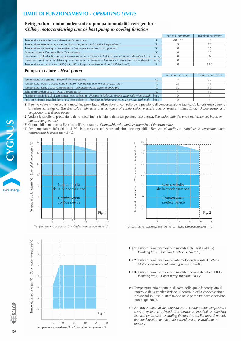
-10
3 6 9 12 15 17
0
10
20
30
40
50
42
46
8 14.5
(*)
LIMITI DI FUNZIONAMENTO - OPERATING LIMITS
36
®
minimo minimum massimo maximum
Temperatura aria esterna - External air temperature °C -10 (1) / 5 (2)
Temperatura ingresso acqua evaporatore - Evaporator inlet water temperature (3) °C 5 20Temperatura uscita acqua evaporatore - Evaporator outlet water temperature (4) °C 0 15Salto termico dell’acqua - Delta T of the water °C 4 10Pressione circuiti idraulici lato acqua senza serbatoio - Pressure in hidraulic circuits water side without tank bar g 0 6Pressione circuiti idraulici lato acqua con serbatoio - Pressure in hidraulic circuits water side with tank bar g 0 3Temperatura evaporazione (DEW) (CG/MC) - Evaporating temperature (DEW) (CG/MC) °C 0 14.5
-10
3 6 9 12 15 17
0
10
20
30
40
50
42
46
8
(*)
Tem
pera
tura
ari
a es
tern
a °C
- E
xter
nal a
ir te
mpe
ratu
re °
C
Temperatura uscita acqua °C - Outlet water temperature °C
Tem
pera
tura
ari
a es
tern
a °C
- E
xter
nal a
ir te
mpe
ratu
re °
C
Temperatura di evaporazione (DEW) °C - Evap. temperature (DEW) °C
Con controllo della condensazione
Condensation control device
Con controllo della condensazione
Condensation control device
(1) Il primo valore si riferisce alla macchina provvista di dispositivo di controllo della pressione di condensanzione (standard), la resistenza carter ela resistenza antigelo. The first value refer to a unit complete of condensation pressure control system (standard), cranckcase heater andevaporator anti-freeze heater.
(2) Vedere le tabelle di prestazione delle macchine in funzione della temperatura lato utenza. See tables with the unit’s performances based onthe user temperatures
(3) Compatibilmente con la FW max dell’evaporatore. Compatibly with the maximum FW of the evaporator.(4) Per temperature inferiori ai 5 °C, è necessario utilizzare soluzioni incongelabili. The use of antifreeze solutions is necessary when
temperature is lower than 5 °C.
minimo minimum massimo maximum
Temperatura aria esterna - External air temperature °C (2) 20Temperatura ingresso acqua condensatore - Condenser inlet water temperature (3) °C 25 45Temperatura uscita acqua condensatore - Condenser outlet water temperature °C 30 50Salto termico dell’acqua - Delta T of the water °C 4 10Pressione circuiti idraulici lato acqua senza serbatoio - Pressure in hidraulic circuits water side without tank bar g 0 6Pressione circuiti idraulici lato acqua con serbatoio - Pressure in hidraulic circuits water side with tank bar g 0 3
Pompa di calore - Heat pump
30
-10 0 5 10 20 30
35
40
45
50
60
70
-3
Tem
pera
tura
usc
ita a
cqua
°C
-
Out
let w
ater
tem
pera
ture
°C
Temperatura aria esterna °C - External air temperature °C
Fig. 1 Fig. 2
Fig. 3
Fig 1: Limiti di funzionamento in modalità chiller (CG-HCG)Working limits in chiller function (CG-HCG)
Fig 2: Limiti di funzionamento unità motocondensante (CG/MC)Motocondensing unit working limits (CG/MC)
Fig 3: Limiti di funzionamento in modalità pompa di calore (HCG)Working limits in heat pump function (HCG)
(*): Temperatura aria esterna al di sotto della quale è consigliato ilcontrollo della condensazione. Il controllo della condensazioneè standard in tutte le unità tranne nelle prime tre dove è previstocome opzionale.
(*): For lower external air temperature a condensation temperaturecontrol system is advised. This device is installed as standard features for all sizes, excluding the first 3 ones. For these 3 models the condensation temperature control system is available on request.
Refrigeratore, motocondensante o pompa in modalità refrigeratoreChiller, motocondensing unit or heat pump in cooling function
CY
GN
US

COEFFICIENTI CORRETTIVI - CORRECTION FACTORS
®
37
Moltiplicare le prestazioni della macchina per i coefficienti correttivi riportati in tabella. (es. Pf(new) = Pf x K1) Multiply the unit performance bythe correction factors given in the table. (e.g. Pf(new) = Pf x K1)(1) KFWE1 = coefficiente correttivo (riferito alla potenza frigorifera/potenza termica corretta con K1) per ottenere la portata d’acqua con un saltotermico di 5 °C correction factor (referred to the cooling capacity/heating capacity corrected by K1) to obtain the water flow with a ∆T of 5 °C.
% Glicole etilenico in peso % Ethylene glycol by weight0 10 20 30 40 50
Temperatura di congelamentoFreezing temperature (°C) 0 - 3.7 - 8.7 - 15.3 - 23.5 - 35.6
Fattore correttivo potenza frigorifera/potenza termicaCooling capacity/Heating capacity correction factor K1 1 0.99 0.98 0.97 0.96 0.93
Fattore correttivo potenza assorbitaAbsorbed power correction factor Kp1 1 0.99 0.98 0.98 0.97 0.96
Fattore correttivo perdite di caricoPressure drop correction factor Kdp1 1 1.08 1.17 1.25 1.33 1.41
Coefficiente correttivo portata acqua (1)Water flow correction factor KFWE1 1 1.02 1.05 1.07 1.11 1.13
Fattore di sporcamento scambiat. di calore acqua/refrigerante (m2 °C/W)Water refrigerant heat exchanger fouling factor (m2 °C/W)
5x10⁻⁵ 1x10⁻⁴ 4x10⁻⁴
Fattore correttivo potenza frigorifera/potenza termicaCooling capacity / Heating capacity correction factor
k2 1 0.99 0.97
Fattore correttivo potenza assorbitaAbsorbed power correction factor
kp2 1 0.99 0.98
Per valutare l’effetto dello sporcamento dello scambiatore di calore acqua/refrigerante, moltiplicare la resa frigorifera Pf per k2 e la potenzaassorbita Pa per kp2. (es. Pf(new) = Pf x k2, Pa(new) = Pa x kp2) To determine the effect of fouling on the water/refrigerant heat exchanger, multiplythe cooling capacity Pf by k2 and the absorbed power Pa by kp2. (e.g. Pf(new) = Pf x k2, Pa(new) = Pa x kp2).
Moltiplicare le prestazioni della macchina per i coefficienti correttivi riportati in tabella. (es. Pf(new) = Pf x K4, Pa(new) = Pa x Kp4) Multiply the unit performance by the correction factors given in table (e.g. Pf(new) = Pf x K4, Pa(new) = Pa x Kp4).La nuova portata d’acqua attraverso l’evaporatore si calcola per mezzo della seguente relazione Fw (m3/h) = Pf(new) (kW) x 0,86 / ∆T dove ∆T èla differenza di temperatura attraverso l’evaporatore (°C). The new water flow to the evaporator is calculated by means of the following equation: Fw (m3/h) = Pf(new) (kW) x 0,86 / ∆T where ∆T is thedeltaT of the water through the evaporator (°C).
∆T 4 5 6 7 8 9 10
Fattore correttivo potenza frigorifera/potenza termicaCooling capacity/Heating capacity correction factor K4 0.99 1 1.01 1.01 1.05 1.02 1.03
Fattore correttivo potenza assorbitaAbsorbed power correction factor Kp4 0.99 1 1.00 1.01 1.01 1.04 1.08
Moltiplicare le prestazioni della macchina per i coefficienti correttivi riportati in tabella (Pf(new) = Pf x K3, Pa(new) = Pa x Kp3, Ph(new) = Ph x K3).Multiply the unit performance by the correction factors given in the table. (Pf(new) = Pf x K3, Pa(new) = Pa x Kp3, Ph(new) = Ph x K3).(*) Per ottenere la max (min.) temperatura aria esterna sottrarre (sommare) i valori indicati dai (ai) valori di max (min.) temperatura aria esternadella tabella prestazioni (Ta(new) = Ta -(+) Kt3).(*) To obtain the maximum (minimum) external air temperature, subtract (add) the values indicated from (to) the maximum (minimum) externalair temperature in the performance table (Ta(new) = Ta -(+) Kt3).
Altitudine Altitude0 500 1000 1500 2000 2500
Fattore correttivo potenza frigorifera/potenza termicaCooling capacity/Heating capacity correction factor K3 1 0.99 0.98 0.98 0.97 0.96
Fattore correttivo potenza assorbitaAbsorbed power correction factor Kp3 1 1.01 1.01 1.02 1.03 1.03
Riduzione max temperatura aria esterna (*)Derating of the max external air temperature (*) Kt3(°C) 0 0.6 1.1 1.8 2.5 3.3
Fattori di sporcamento - Fouling factors
Soluzioni di acqua e glicole etilenico - Solutions of water and ethylene glycol
Coefficienti correttivi scambiatori di calore aria/refrigeranteAir/refrigerant heat exchanger correction factors
Coefficienti correttivi ∆T ≠ 5 °C Correction factors ∆T ≠ 5 °C
CY
GN
US
CY
GN
US

PERDITE DI CARICO EVAPORATORE - EVAPORATOR PRESSURE DROPS®
38
10
20
30
40
50
2
60
70
4 6 8 10
CG
015
CG
020
CG
031
CG
051
12 14 16
80
90
100
CG
071
CG
081
CG
101
CG 1
31
CG 1
71
CG 2
11
CG 2
51
CG 301
CG
013
PERDITE DI CARICO NEGLI EVAPORATORI CYGNUS - EVAPORATOR PRESSURE DROPS CYGNUS
portata acqua water flow FW [m3/h]
perd
ita d
i car
ico
pr
essu
re d
rop∆
P [k
Pa]
10
20
30
40
50
2
60
70
4 6 8 10 12 14 16
80
90
100
HC
G 0
13H
CG
015
HC
G 0
20
HC
G 0
31
HC
G 0
51
HC
G 0
71
HC
G 0
81
HCG
101
HCG
131
HCG
171
HCG
211
HCG
251
- H
CG 3
01
PERDITE DI CARICO NEGLI EVAPORATORI HCYGNUS - EVAPORATOR PRESSURE DROPS HCYGNUS
portata acqua water flow FW [m3/h]
perd
ita d
i car
ico
pr
essu
re d
rop∆
P [k
Pa]
CY
GN
US

CY
GN
US
39
®
CY
GN
US
DISEGNI DI INGOMBRO - OVERALL DIMENSIONS
Ø OUT Rp 1"Ø IN Rp 1" 148 41
65
118.
5
960.5
985
656.5151.5 196
19.5 Ø 13
250
min
.
1000 min.
1000 min.
370
81.5
76
10 360 10
n° 2+2 Ø 10
CG / HCG 013 - 015 - 020
Ø IN: Ingresso acqua - Water inlet
Ø OUT: Uscita acqua - Water outlet
Scarico acqua - Water discharge
Flusso aria - Air flow
Alimentazione elettrica - Power supply
Ø OUT 12 ODF
Ø IN 8 ODF
Versione motocondensante
Remote evaporation version
Ø OUT 16 ODF
Ø IN 8 ODF
Versione motocondensante
Remote evaporation version
CG/MC - HCG/MC 013 CG/MC - HCG/MC 015 - 020
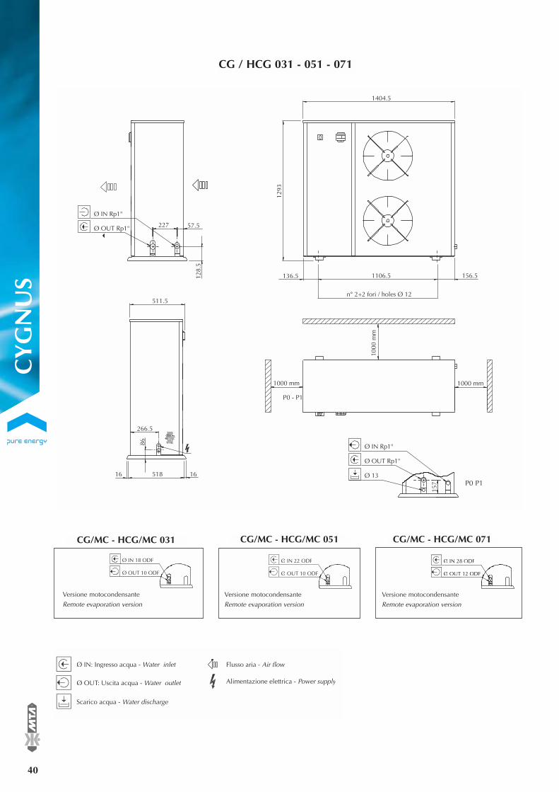
40
®
CG / HCG 031 - 051 - 071
Ø IN Rp1"
Ø OUT Rp1" 227 57.5
128.
5
157
P0 - P1
n° 2+2 fori / holes Ø 12
1106.5136.5 156.5
1404.5
1293
86
266.5
1651816
511.5
1000 mm
1000
mm
1000 mm
Ø IN Rp1"
Ø OUT Rp1"
Ø 13
Ø IN 18 ODF
Ø OUT 10 ODF
Versione motocondensante
Remote evaporation version
Ø IN 22 ODF
Ø OUT 10 ODF
Versione motocondensante
Remote evaporation version
Ø IN 28 ODF
Ø OUT 12 ODF
Versione motocondensante
Remote evaporation version
CG/MC - HCG/MC 031
Ø IN: Ingresso acqua - Water inlet
Ø OUT: Uscita acqua - Water outlet
Scarico acqua - Water discharge
Flusso aria - Air flow
Alimentazione elettrica - Power supply
CG/MC - HCG/MC 071CG/MC - HCG/MC 051
P0 P1
CY
GN
US

®
41
CG / HCG 081 - 101
162.5
Ø OUT Rp1" 1/4
Ø IN Rp1" 1/4
110
146
29213 131340 292
31 1959 6.5
n° 2+2 fori / holes Ø 12
1000 min1000 min
1000
min
1000
min
809
1183
35 730 35
Ø IN 28 ODF
Ø OUT 12 ODF
Versione motocondensante
Remote evaporation version
Ø IN 35 ODF
Ø OUT 16 ODF
Versione motocondensante
Remote evaporation version
Ø IN: Ingresso acqua - Water inlet
Ø OUT: Uscita acqua - Water outlet
Flusso aria - Air flow
Alimentazione elettrica - Power supply
CG/MC - HCG/MC 081 CG/MC - HCG/MC 101
Conditioning your ambient, maximising your comfort.
CY
GN
US
CY
GN
US

42
®
CG / HCG 131 -171
1000 mm
1000
mm
1000
mm
1000 mm
1420302 30213 13
34.5 2060 6
Ø OUT Rp1" 1/2
Ø IN Rp1" 1/2
110
146
162.5
n° 2+2 fori / holes Ø 12
103235 35
1112
1417
Ø IN 35 ODF
Ø OUT 16 ODF
Versione motocondensante
Remote evaporation version
Ø IN 35 ODF
Ø OUT 18 ODF
Versione motocondensante
Remote evaporation version
Ø IN: Ingresso acqua - Water inlet
Ø OUT: Uscita acqua - Water outlet
Flusso aria - Air flow
Alimentazione elettrica - Power supply
CG/MC - HCG/MC 171CG/MC - HCG/MC 131
CY
GN
US

®
43
CG / HCG 211 - 251 - 301
312312 181013 13
n° 2+2 fori / holes Ø 12
247034.5
162.5
146
110
1000
mm
1000 mm1000 mm
1000
mm
1598
1112
Ø OUT Rp 2"
Ø IN Rp 2"
104031 31
Ø IN 35 ODF
Ø OUT 18 ODF
Versione motocondensante
Remote evaporation version
Ø IN 42 ODF
Ø OUT 22 ODF
Versione motocondensante
Remote evaporation version
Ø IN 42 ODF
Ø OUT 22 ODF
Versione motocondensante
Remote evaporation version
Ø IN: Ingresso acqua - Water inlet
Ø OUT: Uscita acqua - Water outlet
Flusso aria - Air flow
Alimentazione elettrica - Power supply
CG/MC - HCG/MC 301CGMC - HCG/MC 251CG/MC - HCG/MC 211
Conditioning your ambient, maximising your comfort.
CY
GN
US
CY
GN
US

44
®GUIDA ALL’INSTALLAZIONE - INSTALLATION GUIDE
L’installazione dei refrigeratori / pompe di calore deve rispettare leseguenti indicazioni:
a) Le unità devono essere installate orizzontalmente per garantireun corretto ritorno dell’olio ai compressori.
b) Osservare gli spazi di rispetto previsti indicati a catalogo.
c) Per quanto possibile, posizionare la macchina in modo da minimizzare gli effetti dovuti alla rumorosità, alle vibrazioni, etc. In particolare, installare la macchina distante, per quanto possibile, da zone in cui il rumore del refrigeratore potrebbe risultare di disturbo, evitare di installare il refrigeratore sotto finestre o tra due abitazioni. Le vibrazioni trasmesse al suolo devono essere ridotte tramite l’impiego di dispostivi antivibranti montati al di sotto della macchina, di giunti flessibili sulle tubazioni dell’acqua e sulle canaline che contengono i cavi di alimentazione elettrica.
d) Effettuare il collegamento elettrico della macchina consultandosempre gli schemi elettrici forniti a corredo.
e) Effettuare il collegamento idraulico della macchina prevedendo:- giunti antivibranti;- valvole di intercettazione;- sfiati nei punti più alti dell’impianto;- drenaggi nei punti più bassi dell’impianto;- pompa e vaso di espansione (se non già previsti nella macchina)- filtro per l’acqua (40 mesh) in ingresso sull’evaporatore.
f) Predisporre opportune barriere frangivento in vicinanza delle batterie condensanti qualora sia richiesto il funzionamento del refrigeratore con temperatura aria esterna sotto i 0 °C e si prevedeche le batterie condensati possano essere investite da vento a velocità superiore ai 2 m/s.
g) Nel caso di potenze frigorifere/termiche richieste maggiori di quelle massime disponibili con una solo macchina, le unitàpossono essere collegati idraulicamente in parallelo, avendo cura di sceglire unità possibilmente identiche per non creare sbilanciamenti nelle portate d’acqua.
h) Nel caso di elevate differenze di temperatura del fluido da trattare, le macchine possono essere collegate idraulicamente in serie e ciascuna unità provvede a fornire una porzione del salto termico dell’acqua.
i) Nel caso di utilizzo di più refrigeratori/pompe di calore collocatiparallelamente con le batterie condensanti affacciate tra loro ènecessario assicurare una distanza minima tra le batterie condensanti. Le distanze minime consigliate tra le unità sono indicate nei disegni di ingombro.
l) Nel caso di necessità di trattare portate d’acqua maggiori di quella massima consentita dal refrigeratore/pompa di calore, è conveniente disporre un by-pass tra ingresso e uscita dal refrigeratore.
m) Nel caso di necessità di trattare portate d’acqua minori di quellaminima consentita dal refrigeratore, è conveniente disporre un by-pass tra uscita e ingresso dal refrigeratore.
n) Si raccomanda di sfiatare accuratamente l’impianto idraulico inquanto anche una piccola quantità d’aria può causare il congelamento dell’evaporatore.
o) Si raccomanda di scaricare l’impianto idraulico durante le sosteinvernali o, in alternativa, di usare miscele anticongelanti. Inoltre siconsiglia, particolarmente nel caso di brevi soste, di richiedere ilrefrigeratore con resistenza antigelo sull’evaporatore e di provvedere ad applicare altre resistenze scaldanti sulle tubazioni del circuito idraulico.
The installation of the chiller / heat pump must adhere to the following:
a) The units must be installed level to guarantee a correct return of theoil to the compressor.
b) To observe the correct space requirements as indicated in the catalogue for maintenance and airflow.
c) Where possible, to install the unit in a way to minimisehe effects of noise, vibration, etc. In particular, do not to install the chiller in areas wherethe noise could cause nuisance as under windows or between tworesidences. The vibrations transmitted to the ground must be reduced by using anti-vibration mounts, flexible joints onthe water pipelines and on the conduit containing the cableof the electrical supply.
d) For electrical connections, always consult the electrical drawingsdispatched with each chiller.
e) Make the unit’s hydraulic connection as indicated:- Anti-vibration joints;- Shut off valves;- Vents on the highest points of the installation;- Drains on the lowest points of the installation;- Pump and expansion vessel;- Water filter (40 mesh) on the evaporator inlet.
f) Place a suitable wind barrier in proximity of the condenser coilsif the chiller works with external air temperature below 0 °C andthere is a possibility that the condenser coils could come in contact with wind speed higher than 2 m/s.
g) In the case of cooling/heating capacity greater thanthe maximum available from a single unit, the hydraulic systemof the chiller can be connected in parallel,possibly selecting thesame type of unit just to avoid water flow imbalance.
h) When high temperature differences of the fluid to be treated, thehydraulic system of the chillers can be connectedin series so each chiller provides a portion of the delta T inthe water.
i) When utilising multiple chillers / heat pump in parallel, with thecondenser coils face to face it is necessary to assure a minimumdistance between the condensers coils. The minimum distancesrecommend between the units are suggested in the overall dimensions.
l) In the case of water flow greater than the maximum allowed by theunit, it is necessary to fit a by-pass between inlet and outlet of thechiller.
m) In the event of water flow lesser than the minimumallowed by the unit, fit a by-pass between outlet and inlet of thechiller.
n) It is recommend to purge all air from the hydraulic systembecause a small quantity of air could cause freezing in the evaporator.
o) During inactivity in winter, the hydraulic system must bedischarged or, alternatively, antifreeze must be used.Again we suggest, specifically for brief unit stops,the use of an antifreezing heater around evaporator and otherantifreezing heaters on the cooling circuit tubes.
CY
GN
US


EHC
GY
000D
Ied
. 06/
2007
CYGNUSCYGNUS HCYGNUS CYGNUS/MC HCYGNUS/MC
La MTA nell’ottica di un miglioramento continuo del prodotto, si riserva il diritto di cambiare i dati presenti in questo catalogo senza obbligo di preavviso. Per ulteriori informazioni rivolgersi agli uffici commerciali. La riproduzione, anche parziale, é vietata.
The data contained herein is not binding. With a view to continuous improvement, MTA reserves the right to make changes without prior notice. Please contact our sales office for further information. Reproduction in whole or in part is forbidden.
INNOVAZIONE PURA, SODDISFAZIONE PURA, ENERGIA PURAMTA nasce 25 anni fa con un chiaro obiettivo: migliorare il rapporto tra l’uomo e due diverse risorse naturali, l’aria e l’acqua, ottimizzandone la trasformazione in fonti energetiche. Investendo nell’innovazione, MTA è sempre in grado di proporre tecnologie all’avanguardia, mentre un team di esperti a livello mondiale è la garanzia della massima soddisfazione per i clienti.
PURE INNOVATION, PURE SATISFACTION, PURE ENERGYMTA was born over 25 years ago with a clear objective: improving mankind’s relationship with two distinct natural resources, air and water, and optimising their transformation into energy sources.Our investment in Innovation ensures we offer the very latest technologies, whilst an expert team worldwide ensures our Customers achieve the highest levels of Satisfaction. At MTA energy is our business, and improving your relationship with your energy is our aim.
DIVERSIFICAZIONE STRATEGICAMTA copre tre diversi segmenti di mercato. Oltre alle soluzioni per la climatizzazione, offre una serie comple-ta di prodotti destinati al mercato della refrigerazione dei processi industriali e una vasta gamma di soluzioni per il trattamento dell'aria compressa e dei gas.MTA è da sempre nota per le innovazioni introdotte in ciascuno di questi settori. La diversificazione strategica adottata offre dunque ai Clienti dei benefici unici, inediti nei singoli ambiti di applicazione.
STRATEGIC DIVERSIFICATIONMTA covers three distinct market segments. As well as Air Conditioning solutions, we offer a complete series of products for the Industrial Process Cooling market, as well as an extensive range of Compressed Air & Gas Treatment solutions.MTA has always been known for the innovation it has brought into each of these three sectors; in fact our strategic diversification offers our Customers unique benefits unseen in their individual fields.
IN TUTTO Il MONDO, MA A PORTATA DI MANOMTA ha rappresentanze in 60 paesi nel mondo. 8 commerciali MTA in 4 continenti.I suoi collaboratori e rappresentanti vantano conoscenze tecniche specifiche e ricevono aggiornamenti continui. I clienti MTA hanno la certezza di poter contare, nel tempo, su un'assistenza attenta e metico-losa e su soluzioni energetiche ottimizzate.MTA è sempre vicina ai suoi clienti, ovunque si trovino.
FAR REACHING BUT AlWAYS ClOSE BYMTA is officially represented in some 60 countries worldwide. 8 MTA Sales Companies cover 4 continents.Our staff and representatives boast expert knowledge and benefit from continuous training. Accurate at-tention to service support guarantees that our Customers can look forward to long term peace of mind and an optimized energy solution.We always remain close to our Customers, so wherever you may be, we will be near to you.
www.mta-it.com M.T.A. S.p.A. Viale Spagna, 8 - ZI35020 Tribano (PD) - ItalyTel. +39 049 [email protected]
Condizionamento Air conditioningFax +39 049 9588604
Refrigerazione industriale Process coolingFax +39 049 9588661
Trattamento aria compressa Compressed air treatmentFax +39 049 9588612
For information concerning your nearest MTA representativeplease contact M.T.A. S.p.A.
MTA Australasia+61 3 9702 4348www.mta-au.com
MTA China+86 21 5417 1080www.mta-it.com.cn
MTA France+33 04 7249 8989www.mtafrance.fr MTA Germany+49 2163 5796-0www.mta.de
MTA Romaniawww.mta-it.ro
MTA Spain+34 938 281 790www.novair.es
MTA USA+1 716 693 8651www.mta-it.com
Sost
ituis
ce il
/rep
lace
the
EHC
GY
000D
H