Embed Size (px)
Citation preview

Safe-Lec 2 Conductor Bar Manual964200.12
Conductor Bar ManualSafe-Lec 2 “V” Contact Barwww.conductix.us

2 Safe-Lec 2 Conductor Bar Manual
CONDUCTIX INCORPORATEDThe technical data and images which appear in this manual are for informational purposes only. NO WARRANTIES, EXPRESS OR IMPLIED, INCLUDING WARRANTIES OF MERCHANTABILITY OR FITNESS FOR A PARTICULAR PURPOSE, ARE CREATED BY THE DESCRIPTIONS AND DEPICTIONS OF THE PRODUCTS SHOWN IN THIS MANUAL. Conductix-Wampfler makes no warranty (and assumes no liability) as to function of equipment or operation of systems built according to customer design or of the ability of any of its products to interface, operate or function with any portions of customer systems not provided by Conductix-Wampfler.
Seller agrees to repair or exchange the goods sold hereunder necessitated by reason of defective workmanship and material discovered and reported to Seller within one year after shipment of such goods to Buyer.
Except where the nature of the defect is such that it is appropriate, in Seller’s judgment, to effect repairs on site, Seller’s obligation hereunder to remedy defects shall be limited to repairing or replacing (at Seller’s option) FOB point of original shipment by Seller, any part returned to Seller at the risk and cost of Buyer. Defective parts replaced by Seller shall become the property of Seller.
Seller shall only be obligated to make such repair or replacement if the goods have been used by Buyer only in service recommended by Seller and altered only as authorized by Seller. Seller is not responsible for defects which arise from improper installation, neglect, or improper use or from normal wear and tear.
Additionally, Seller’s obligation shall be limited by the manufacturer’s warranty (and is not further warranted by Seller) for all parts procured from others according to published data, specifications or performance information not designed by or for Seller.
Seller further agrees to replace or at Seller’s option to provide a refund of the sales price of any goods that do not conform to applicable specifications or which differ from that agreed to be supplied which non-conformity is discovered and forthwith reported to Seller within thirty (30) days after shipment to the Buyer. Seller’s obligation to replace or refund the purchase price for non-conforming goods shall arise once Buyer returns such goods FOB point of original shipment by Seller at the risk and cost of Buyer. Goods replaced by Seller shall become the property of Seller.
There is no guarantee or warranty as to anything made or sold by Seller, or any services performed, except as to title and freedom from encumbrances and, except as herein expressly stated and particularly, and without limiting the foregoing, there is no guarantee or warranty, express or implied, of merchantability or of fitness for any particular purpose or against claim of infringement or the like.Seller makes no warranty (and assumes no liability) as to function of equipment or operation of systems built to Buyer’s design or of the ability of any goods to interface, operate or function with any portions of Buyer’s system not provided by Seller.
Seller’s liability on any claim, whether in contract, tort (including negligence), or otherwise, for any loss or damage arising out of, connected with, or resulting from the manufacture, sale, delivery, resale, repair, replacement or use of any products or services shall in no case exceed the price paid for the product or services or any part thereof which give rise to the claim. In no event shall Seller be liable for consequential, special, incidental or other damages, nor shall Seller be liable in respect of personal injury or damage to property not the subject matter hereof unless attributable to gross misconduct of Seller, which shall mean an act or omission by Seller demonstrating reckless disregard of the foreseeable consequences thereof.
Seller is not responsible for incorrect choice of models or where products are used in excess of their rated and recommended capacities and design functions or under abnormal conditions. Seller assumes no liability for loss of time, damage or injuries to property or persons resulting from the use of Seller’s products. Buyer shall hold Seller harmless from all liability, claims, suits and expenses in connection with loss or damage resulting from operation of products or utilization of services, respectively, of Seller and shall defend any suit or action which might arise there from in Buyer’s name - provided that Seller shall have the right to elect to defend any such suit or action for the account of Buyer. The foregoing shall be the exclusive remedies of the Buyer and all persons and entitles claiming through the Buyer.

Safe-Lec 2 Conductor Bar Manual 3
TABLE OF CONTENTSSECTION 1 - SAFETY 6Safety Information Responsibility 6Safety Messages 6
SECTION 2 - OVERVIEW 7Conductor System Nomenclature 7Typical 3-Phase System Overview 8Environmental Considerations 9Installation Tools 10
SECTION 2 - GENERAL ASSEMBLY INSTRUCTIONS 11Installation Overview 11Identifying and Organizing the Materials 11Install Brackets 11Final Installation Along the Runway 11Collector Positioning 12
SECTION 3 - SUPPORT BRACKETS 13Support Bracket Installation 13
SECTION 4 - CONDUCTOR HANGERS 14Four Bar Conductor Hanger Mounting 14Tools Needed 14Mounting Instructions 14Installing Conductors Into Hanger 15
SECTION 5 - ANCHOR HANGER SUPPORT ASSEMBLY 16Tools Needed 16Anchor Hanger Support Installation 16
SECTION 6 - BOLTED STEEL/COPPER JOINT ASSEMBLY 17Tools Needed 17Bolted Steel/Copper Joint Installation 17
SECTION 7 - BOLTED ALUMINIUM JOINT ASSEMBLY 18Tools Needed 18Bolted Aluminium Joint Installation 18
SECTION 8 - JOINT COVER ASSEMBLY 19Joint Cover Installation 19
SECTION 9 - END CAP ONTO CONDUCTOR BAR ASSEMBLY 20Galvanized Steel and Copper Conductor Bar Installation 20
Tools Needed 20Installation 20
Aluminium/Stainless Steel Conductor Bar Installation 21Tools Needed 21Installation 21

4 Safe-Lec 2 Conductor Bar Manual
SECTION 10 - EXPANSION SECTION ASSEMBLY 22Allowable Length and Distance 22Expansion Section Installation 22
SECTION 11- END POWERFEED ASSEMBLY 23Tools Needed 23End Powerfeed Installation 23
SECTION 12 - LOW AMP JOINT POWERFEED ASSEMBLY 24Tools Needed 24Low Amp Joint Powerfeed Installation 24Installation Up to and Including 250 Amps (PN XA-310910B) 25
SECTION 13 - POWERFEED AND COVER ASSEMBLY 26Installation Over 250 Up to 400 Amps (PN XA-310912B) 26
SECTION 14 - TERMINAL CHART FOR GUIDELINES ONLY 27
SECTION 15 - 100 AMP DI COLLECTOR MOUNTING DETAILS 28Installation 28
SECTION 16 - 50 AMP SI COLLECTOR MOUNTING DETAILS 29Installation 29
SECTION 16 - CUSTOMER SUPPLIED CABLE INSTALLATION 30
SECTION 17 - 200 AMP COLLECTOR 31
SECTION 18 - TRANSFER CAP ASSEMBLY 32Tools Needed 32Transfer Cap Installation 32
SECTION 19 - TRANSFER CAP MOUNTING DETAILS 33
SECTION 20 - ASSEMBLY OF ISOLATION SPLICE ASSEMBLIES 34Installation 34
SECTION 21 - SYSTEM MAINTENANCE AND INSTALLATION NOTES 35Maintenance Notes 35Installation Notes 35
SECTION 22 - DI AND SI COLLECTOR CONTACT SHOE AND SHOE HOLDER 36Tools Needed 36Replacement Instructions 36Replacement of 200 Amp Collector Contact Shoe 36
TABLE OF CONTENTS
Safe-Lec 2 Conductor Bar Manual 5
TABLE OF CONTENTSSECTION 23 - ASSEMBLY FOR 1, 2, 3, & 4-WAY PICKUP GUIDE 37Assembly Instructions 37
SECTION 24 - HANGER CENTERS DIAGRAMS 38
SECTION 25 - CONDUCTOR BAR DE-RATING CHART 39

6 Safe-Lec 2 Conductor Bar Manual
SECTION 1 - SAFETYSafety Information ResponsibilityAll owner, operator, and maintenance personnel must read and understand all manuals associated with this product before installation, operation, or maintenance.
The manual provides information on the recommended installation, operation, and maintenance of this product. Failure to read and follow the information provided could cause harm to yourself or others and/or cause product damage. No one should install, operate, or attempt maintenance of this product prior to familiarizing themselves with the information in this manual.
Safety MessagesThe following safety messages are used in this manual to alert you to specific and important safety related information.
CAUTION• CAUTION indicates unsafe actions or situations that have the potential to cause injury, and/or minor equipment or property
damage.
DANGER
• DANGER indicates hazards that have the potential to cause severe personal injury or death.
WARNING• WARNING indicates unsafe actions or situations that have the potential to cause severe injury, death, and/or major equipment or
property damage.
NOTE• NOTE is used to alert you to installation, operation, programming, or maintenance information that is important, but not hazard
related.
SECTION 1 - SAFETY SECTION 2 - OVERVIEW

Safe-Lec 2 Conductor Bar Manual 7
SECTION 2 - OVERVIEW
Single Conductor
Joint Position
Expansion Section
Transfer Cap
End Cap
Isolation Section Isolation = Insulating Material
Hanger Clamp Anchor Position
Powerfeed
Pickup Guide
Isolation Section Isolation = Air Gap
Collector
Power Interrupt
SECTION 2 - OVERVIEW
Conductor System Nomenclature

8 Safe-Lec 2 Conductor Bar Manual
SECTION 2 - OVERVIEW
246’
(75M
) Max
. on
all
bars
unl
ess
othe
rwis
e
spec
ified
8.0”
(203
mm
)
Anch
or P
oint
59.0
” (1.
5M) r
ecom
men
ded
hang
er s
pacin
g ve
rtica
l ent
ry. F
or
curv
es a
nd la
tera
l ent
ry 4
4.3”
(1.1
25M
)
End
Cove
rHa
nger
Cla
mp
Note
s: M
axim
um le
ngth
with
out e
xpan
sion
s; 4
92’
(150
M),
use
anch
or c
lam
p at
cen
ter
Join
tAn
chor
Poi
nt14
’-9”
(4.5
M)
Expa
nsio
n Se
ctio
n
120’
(36.
5M) M
ax. A
lum
inum
Bar
s
230’
(70M
) Max
. Ste
el B
ars
160’
(49M
) Max
. Cop
per B
ars
18” (
450m
m) R
ecom
men
ded
6” (1
50m
m) M
inim
um
6” (1
50m
m) M
inim
um
Betw
een
com
pone
nts
Pow
erfe
ed
(Joi
nt p
ower
feed
) lan
ds o
n
splic
e
Max
imum
over
hang
at e
nd 1
2.0”
(305
mm
)
End
Cove
r
Cond
ucto
r Bar
Sect
ion
14’-
9” (4
.5M
)
Typi
cal 3
-Pha
se S
yste
m O
verv
iew
NOTE
• Di
men
sion
s ar
e in
Inch
es (m
m).
• M
axim
um R
ecom
men
ded
Hang
er S
paci
ng:
»1.
5 M
eter
s (5
9.0”
) on
stra
ight
runw
ays
»1.
125
Met
ers
(44.
3”) o
n al
l Lat
eral
Mou
nt S
yste
ms
and
Curv
ed
Syst
ems
(cur
ved
sect
ion
only)
ATTE
NTIO
N•
Curv
ed b
ar to
be
fact
ory
bent
onl
y.
6” (1
50m
m) M
inim
um
Safe-Lec 2 Conductor Bar Manual 9
SECTION 2 - OVERVIEWEnvironmental Considerations• Standard Cover (PVC) is suitable up to 160F.
• Medium Heat Cover (Polycarbonate) is suitable up to 250F.
The following acidic or corrosive environments require the use of stainless steel hangers:
• Hydrochloric Acid
• Hydrofluoric Acid
• Sodium Hydrochloride
• Ammonium Chloride
• Chlorine Bleach
• Chloride Ions
• Fluoride Ions
WARNING• Do not use standard (black) or medium heat (red) hangers in these environments.

10 Safe-Lec 2 Conductor Bar Manual
SECTION 2 - OVERVIEWInstallation Tools• Man lift or platform lift for access to the installation location (if Needed)
• Sharp knife - to cut powerfeed grommets
• Straight blade screwdriver - for securing feed cable to collectors and replacing collector shoes
• Steel rule or tape measure - to position collectors during installation
• Wire/cable stripper
• Cable lug crimping tool (see section 14)
• Cordless drill with socket adapter (1/4” or 3/8” drive)
• Deep sockets for cordless drill
» 8mm - for anchor cross bolts
» 10mm - for splices, isolation sections, and powerfeeds
» 13mm - for mounting hangers, collectors, anchors and transfer caps.
• Torque wrench for sockets listed above
• Open/box end wrenches (use ratcheting box-end wrenches if you have them)
» 8mm
» 10mm
» 13mm
• Hacksaw
• Flat file and/or rat tail file to remove burrs on field cut conductors
• Pliers

Safe-Lec 2 Conductor Bar Manual 11
SECTION 2 - GENERAL ASSEMBLY INSTRUCTIONS
WARNING• Always lock out/tag out all electrical power before starting work.
Installation OverviewThis manual provides detailed instructions in the general order of system installation.
System installation consists of 5 phases:
1. Identifying and organizing the materials
2. Installation of brackets along the runway
3. Pre-install assemblies on the ground
4. Installation of hangers and conductors and final assembly along the runway
5. Installation and alignment of collectors on the crane
Identifying and Organizing the MaterialsCheck the pack list against the items received. Parts are labeled for your convenience. Review your specific installation layout drawing (if provided) or the typical layout diagram seen previously in this manual to become familiar with component location on the system. Note where the anchors, expansions, powerfeeds, and other assemblies will be located along the runway. Read through these instructions before starting work.
NOTE• Make sure to check for smaller components that may be located inside the false bottom of the package.
Install BracketsInstall brackets per the diagram included at the start of this manual. Keep them as level and evenly spaced as possible. You may install the hangers on the brackets before or after they are mounted along the runway.
Assemble as much as possible on the ground. It’s faster, easier, safer, and more convenient should you drop something.
Conductor Bar and Expansion Sections will come from the factory with one splice pre-installed.
1. Install end caps on the end conductors, keeping these separated from the main runway conductors.
2. Install isolation splices (if included) on the ends of the conductors in accordance with the installation layout drawing and the instructions (see Table of Contents).
3. Install transfer caps on the conductor ends (if included).
Final Installation Along the RunwayThe installation will most likely be accomplished from a lift or work platform.
1. Ensure the power is locked out/tagged out.
2. Install the hangers per instructions (see Table of Contents).
3. Roll adjacent conductors in the hangers as shown in Section 4. Conductix-Wampfler recommends the first accessible conductor being the ground conductor.
4. Move down the runway, install the next inboard conductor and join it to the corresponding conductor installed in step 3. Install the splice cover. Keep the splice assemblies 6-12” from the hanger brackets to allow for conductor movement from expansion. Repeat for the remaining phases and ground conductors.
5. When you get to where the expansion assemblies are to be installed, refer to those instructions (see Table of Contents). Be sure to divide the total expansion gap distance (from chart) between the two air gap locations in the expansion assembly.
6. Proceed with system installation, ensuring anchors are positioned the correct distance from the expansions and that they are tightened to the correct torque.
7. If a conductor must be cut to a specific length, ensure that the cut end is properly de-burred. The conductor cover is always shorter than the bar length, the proper cover length is 66mm (2.60”) shorter than bar length. (33mm / 1.30” on each end).
8. When you run the feed cable to the powerfeed assembly, ensure the cables have sufficient free length and are flexible enough to enable movement of the conductor due to expansion. Locating the powerfeed as close as possible to the anchors minimizes this concern. Do not support the weight of the feed cables with the conductors.
9. Install powerfeeds on conductor bars per layout and the instructions (see Table of Contents).
SECTION 2 - GENERAL ASSEMBLY INSTRUCTIONS

12 Safe-Lec 2 Conductor Bar Manual
SECTION 3 - SUPPORT BRACKETS
SECTION 2 - GENERAL INSTALLATION INSTRUCTIONSCollector PositioningCollectors must be properly positioned and aligned to ensure safe, reliable operation.
• The collector mounting post must be 127mm (5.0”) for 200 Amp. collectors, 102mm (4.0”) for 100 Amp. DI collectors and 90mm (3.5”) for 50 Amp. SI collectors, below the contact surface of the conductor and the arms level from end to end.
• Slide the collectors on the mounting staff. Ensure the mounting base of each collector is centered below the corresponding conductor. Ensure the collectors are evenly spaced. Tighten hardware to specifications and connect the supply cable to the collector per diagram (see Table of Contents).
NOTE• Follow lockout/tagout procedures• Keep accessories at least 6” from hanger brackets• Follow all torque specifications• Allow for movement of accessories due to expansion• Connect only flexible power cables to powerfeed assemblies• Keep collectors straight, level and aligned with conductors

Safe-Lec 2 Conductor Bar Manual 13
SECTION 3 - SUPPORT BRACKETSSupport Bracket Installation1. Locate and secure support brackets at the recommended spacing. See Figure 13-1.
NOTE• Locate support brackets at a spacing that is divisible into the conductor bar lengths. This will always ensure that the joint
positions do not interfere with the support brackets.
2. Observe all alignment tolerances. See Figure 13-1.
» Datum height
» Maximum allowable deviation from datum height + 5.0mm (+3/16”).
Straight datum line running entire length of the system.
Alignment tolerance over 4500mm + 5.0(177” + 3/16”).
--
9.00mm wide slot to accommodate 4 anchors on 43.00mm centers
Figure 13-1
Conductix-Wampfler BracketsHanger support brackets come complete with all necessary mounting holes for easy installation of hangers via slide in slots or holes.
SECTION 3 - SUPPORT BRACKETS

14 Safe-Lec 2 Conductor Bar Manual
SECTION 4 - CONDUCTOR HANGERSFour Bar Conductor Hanger Mounting
NOTE• For Indoor and Limited Outdoor use, PN XA-310821.• For Lateral Mount - Consult Factory
Tools Needed• 13mm A/F wrench
Mounting Instructions1. Remove nut, lock washer, and washer from hanger assembly (the M8 bolt will stay in place inside the molding).
2. Assemble as shown in the diagram ensuring the correct alignment is observed. See Figure 14-1.
3. Finger tighten M8 nut.
4. Snap conductor bars into hangers.
5. Tighten M8 nut to Conductix-Wampfler recommended torque of 8 Nm (5-6 ft-lbs.)
NOTE• This hanger may be used outside when the bar system is covered and protected from the elements. If the bar system will be
exposed to rain, snow, ice, fog etc., then a single pole insulated hanger must be used.
SECTION 4 - CONDUCTOR HANGERS
Support Bracket
Alignment tolerance over4500mm + 5mm(177” + 3/16”)
Nut 13mm A/F Zinc plated Grade 8.8
For medium heat hangers 2 flat washers are supplied.
Straight Datum line running the length of the system.
M8 x 30 setscrew Zinc plated Graded 8.8
Figure 14-1

Safe-Lec 2 Conductor Bar Manual 15
SECTION 4 - CONDUCTOR HANGERS
9Visit www.conductix.us for the most current information.
Here are several specific reasons why Safe-Lec 2 is superior to a traditional (and now outmoded) 8-Bar system. And we should know . . . we invented 8-Bar over 50 years ago!
Safe-Lec 2 8-BarQuicker and less costly Installation
• 14.76 ft (4.50m) bar lengths; fewer joints • Multiple pole hangers; a “snap” to install
• Wires connect into lug integrated in the collector arm
• 10 ft (3.05m) bar lengths; more splices required • Hangers hold only one bar each
• Wires must be spliced to collector pigtails
More secure splice joint • Bolted joints • No special tools required • No need for “joint keepers” or “joint repair kits”, etc
• Pinned joint can pull apart; requires special parts
• Special tool required
Fewer expansion sections required • Safe-Lec 2 can go 492 ft (150m) before an expansion is
required • 8-Bar can only go 300 ft before an expansion section is
required (or 200 ft for copper bar)
Easier system alignment • Slotted brackets are available to reduce
hole alignment problems • System alignments are easy!
• Brackets have round holes, so alignment must be perfect • Harder to make system alignment adjustments
Superior Collector Shoe Tracking • Shoe is guided by the V-contact in the metal bar • Collector arm articulates to accommodate mild system
misalignments
• Shoe is guided by the plastic cover • Accurate system alignment is much more critical
Step 1 Step 2“SNAP”
Installed
Safe-Lec 2 Overview & Design Features
Installing Conductors Into Hanger
Figure 15-1
Recommended position for ground bar

16 Safe-Lec 2 Conductor Bar Manual
SECTION 5 - ANCHOR HANGER SUPPORT ASSEMBLY
NOTE• For ease of access to clamping screws, install anchor hanger assemblies as shown below.
Tools Needed• 13mm A/F open ended wrench.
• 8mm A/F open ended wrench.
Anchor Hanger Support Installation1. Assemble anchor over cover so it is free to slide.
2. Insert anchor hanger into support bracket.
3. Tighten M5 Bolts until anchor stops meet (check anchor is tight on cover).
4. Tighten M8 Bolt to a torque of 8 Nm (5-6 ft. lbs.).
SECTION 5 - ANCHOR HANGER SUPPORT ASSEMBLY
Figure 16-1 1. Clamp Anchor Half2. M5 Nut3. M8 Nut4. M8 Screw
5. M5 Screw6. M5 Flat Washer7. M8 Flat Washer8. M8 Lock Washer
1
3
2
4
5
6
7
8

Safe-Lec 2 Conductor Bar Manual 17
SECTION 6 - BOLTED STEEL/COPPER JOINT ASSEMBLYTools Needed• 10mm A/F open ended wrench
Bolted Steel/Copper Joint Installation1. Fit bolt into joint plate (ensure tab captivates the head on the setscrew).
2. Slide bolt and joint plate into conductor bar ends.
3. Place joint over bolt, making sure alignment mark is in line with end faces of conductor bar.
4. Fit washer and nut onto bolt in the order shown.
5. Tighten nut to recommended torque of 8 Nm (5-6 ft-lbs).
6. Check that both faces of the conductor bar are touching each other and there is no gap exceeding 0.5mm (0.02”) at the faces.
NOTE• If the conductor was field cut, file off all burrs on conductor ends before assembling splices.
SECTION 6 - BOLTED STEEL/COPPER JOINT ASSEMBLY
Figure 17-1 1. Nut2. Washer3. Joint4. Bolt
5. Joint Plate6. Conductor Bar7. Alignment Mark
1
3
2
4
5
6
7

18 Safe-Lec 2 Conductor Bar Manual
SECTION 8 - JOINT COVER ASSEMBLY
Joint Cover Installation
SECTION 7 - BOLTED ALUMINIUM JOINT ASSEMBLYTools Needed• 10mm A/F open ended wrench
• Electrical Joint Compound (PN XA-15629)
Bolted Aluminium Joint Installation1. Apply electrical joint compound to all mating surfaces.
2. Slide bolt into conductor bar ends.
3. Place joint plate over bolts.
4. Fit washer and nut as shown.
5. Tighten nut to recommended torque of 8 Nm (5-6 ft-lbs).
6. Check that both faces of conductor bar are touching each other and that there is no gap exceeding 0.5mm (0.02”) at the faces.
NOTE• If the conductor was field cut, file off all burrs on conductor ends before assembling splices. Exposed length of bar should be
33mm (1.3”) per end.
33mm(1.3”)
Apply ElectricalJoint Compound
PN XA-15629 to mating surfaces.
SECTION 7 - BOLTED ALUMINIUM JOINT ASSEMBLY
Figure 18-1 1. Nut2. Washer3. Joint Plate4. Bolt5. Conductor Bar
1
3
2
4
5 5
Safe-Lec 2 Conductor Bar Manual 19
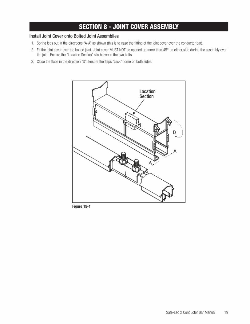
SECTION 8 - JOINT COVER ASSEMBLYInstall Joint Cover onto Bolted Joint Assemblies1. Spring legs out in the directions “A-A” as shown (this is to ease the fitting of the joint cover over the conductor bar).
2. Fit the joint cover over the bolted joint. Joint cover MUST NOT be opened up more than 45° on either side during the assembly over the joint. Ensure the “Location Section” sits between the two bolts.
3. Close the flaps in the direction “D”. Ensure the flaps “click” home on both sides.
Location Section
SECTION 8 - JOINT COVER ASSEMBLY
Joint Cover Installation
Figure 19-1
D

20 Safe-Lec 2 Conductor Bar Manual
Aluminium/Stainless Steel Conductor Bar Installation
SECTION 9 - END CAP ONTO CONDUCTOR BAR ASSEMBLYGalvanized Steel and Copper Conductor Bar InstallationInstall end caps onto galvanized steel and copper conductor bars. See Figure 20-1.
Tools Needed• 10mm A/F open ended wrench
Installation1. Fit bolt into joint plate (ensure tab captivates the head on the set screw).
2. Place bolt and joint plate assembly into conductor bar.
3. Place end cover clamp, washer, and nut over bolt and joint plate assemblies (ensure end cover clamp is flush with conductor bar face).
4. Tighten nut to a recommended torque of 8 Nm (5-6 ft-lbs).
5. Push end cover over assembly (ensure bolt is located in point “A” on end cover).
NOTE:Wings on Tab toface upwards.
This face to be flushwith conductor face.
SECTION 9 - END CAP ONTO CONDUCTOR BAR ASSEMBLY
Galvanized Steel and Copper Conductor Bar Installation
Figure 20-1 1. Nut2. Washer3. End Cover Clamp
4. Bolt5. Joint Plate6. End Cover
3
2
4
5
6
A
1
Safe-Lec 2 Conductor Bar Manual 21
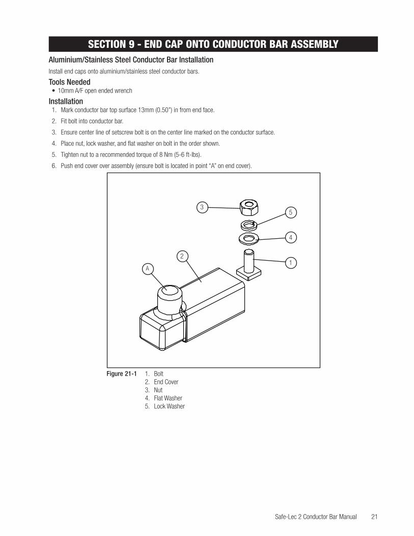
SECTION 9 - END CAP ONTO CONDUCTOR BAR ASSEMBLYAluminium/Stainless Steel Conductor Bar InstallationInstall end caps onto aluminium/stainless steel conductor bars.
Tools Needed• 10mm A/F open ended wrench
Installation 1. Mark conductor bar top surface 13mm (0.50”) in from end face.
2. Fit bolt into conductor bar.
3. Ensure center line of setscrew bolt is on the center line marked on the conductor surface.
4. Place nut, lock washer, and flat washer on bolt in the order shown.
5. Tighten nut to a recommended torque of 8 Nm (5-6 ft-lbs).
6. Push end cover over assembly (ensure bolt is located in point “A” on end cover).
250
UNIT
A
MINIMUM MACHINED SURFACE
Aluminium/Stainless Steel Conductor Bar Installation
Figure 21-1 1. Bolt2. End Cover3. Nut4. Flat Washer5. Lock Washer
1
3
2
4
5
A

22 Safe-Lec 2 Conductor Bar Manual
SECTION 10 - EXPANSION SECTION ASSEMBLYAllowable Length and Distance• The maximum allowable conductor system length without an Expansion Section is 150 meters (492’) - Assuming a Maximum
Temperature Range of 110°F
• The maximum distance between anchor points with an Expansion Section at mid-point is 70m (230’) steel, 49m (160’) copper, 36.5m (120’) aluminum
Expansion Section Installation1. Set expansion air gaps when installing assembly to appropriate gap setting for ambient temperature (see Table 22-1). The gap
is adjusted by sliding the moving lengths of conductor in or out of the expansion assembly (BOTH HALVES MUST BE SET EQUAL). Always allow sufficient time for the conductor bars to achieve ambient temperature before setting Expansion gap. All Expansion assemblies must be set at site, they are not pre-set before leaving the factory. Failure to set this part correctly could result in buckling of all conductors.
2. Set anchor clamp and torque on one side, install up to next anchor clamp but DO NOT TIGHTEN. Go back and set expansion to correct gap setting per current ambient temperature. Once gap is set, go to second anchor clamp and tighten.
Half Total Air Gap Half Total Air Gap
ACTUAL SITE AMBIENT: OC (OF)
TOTA
L GA
P SE
TTIN
G: m
m (i
n)
LOW
EST
POSS
IBLE
SIT
E AM
BIEN
T O C
(O F) [S
EE N
OTE]
SECTION 10 - EXPANSION SECTION ASSEMBLY
Table 22-1 Expansion Air Gap Setting For Conductor Bars With PVC Cover

Safe-Lec 2 Conductor Bar Manual 23
SECTION 11 - END POWERFEED ASSEMBLY
NOTE• Installation is for 100 Amp Conductor Bar only.
Tools Needed• 10mm A/F Wrench
• Suitable Sharp Knife
• Cable Stripper
• Cable Crimping Tool
• Suitable Cable Terminal (see list of recommended suppliers and references).
End Powerfeed Installation1. Cut powerfeed end cap to suit cable diameter.
2. Pass cable through powerfeed end cap.
3. Crimp terminal to cable.
4. Fit bolt into joint plate (wings on tab to face upward).
5. Fit assembly into conductor bar.
6. Fit clamp end over joint plate and bolt. Secure with half nut. Tighten half nut to recommended torque value of 10Nm (7-8 ft-lbs).
7. Fit terminal and secure washer and nut.
8. Tighten nut to recommended torque of 8 Nm (5-6 ft-lbs).
9. Push powerfeed end cap over assembly (ensure bolt is located in point “A” on powerfeed end cap).
NOTE• Max cable size is 25 sq. mm pvc 600/1000V stranded copper conductor (#4 AWG Extra Flexible).
SECTION 11- END POWERFEED ASSEMBLY
These facesto be flush
Figure 23-1 1. Joint Plate2. Bolt3. Clamp End4. Half Nut
5. Washer6. Nut7. Powerfeed End Cap
1
3
2
4
5
6
7
A

24 Safe-Lec 2 Conductor Bar Manual
SECTION 12 - LOW AMP JOINT POWERFEED ASSEMBLY
NOTE• Installation up to 100 Amp.
Tools Needed• 10mm A/F Wrench
• Suitable Sharp Knife
• Cable Stripper
• Cable Crimping Tool
• Suitable Cable Terminal (see list of recommended suppliers and references).
Low Amp Joint Powerfeed Installation1. Remove black plug on powerfeed cap.
2. Assemble joint to conductor bar as described previously.
3. Pass supply cable through grommet.
4. Crimp terminal to supply cable.
5. Secure terminal to joint using washer and nut and tighten nut to a recommended torque of 8 Nm (5-6 ft-lbs).
6. Fit powerfeed cap over assembly (ensure the cable is threaded carefully through grommet).
7. Once in position close flaps and ensure flaps click home.
NOTE• Joint must not support the cable. • Max cable size 10sq. mm pvc 600/1000V stranded copper conductor (#8 AWG Extra Flexible).
SECTION 12 - LOW AMP JOINT POWERFEED ASSEMBLY
Figure 24-1 1. Washer2. Nut3. Powerfeed Cap
1
3
2

Safe-Lec 2 Conductor Bar Manual 25
SECTION 12 - LOW AMP JOINT POWERFEED ASSEMBLYNOTE• Clean all mating surfaces with 3M Scotch Brite Pad, apply a small amount of Electrical Joint Compound (EJC) to all mating parts.• Apply anti-seize to bolt ends prior to assembly to any stainless steel nuts.
Installation Up to and Including 250 Amps (PN XA-310910B)1. Assemble joint to conductor bar as described previously (do not fit washers and nuts).
2. Fit powerfeed top hat assembly to joint assembly. On copper and aluminum conductors apply Electrical Joint Compound (EJC) between mating surfaces.
3. Discard spring washers originally fitted to the joint assembly and fit external tooth lock washers (supplied in the kit) along with nuts and bolts and tighten to a recommended torque of 8 Nm (5-6 ft-lbs).
4. Fit joint powerfeed cover as shown previously.
5. Cut out grommet using suitable knife and fit over cable.
6. Crimp terminal to supply cable (see list of recommended terminals).
7. Ensure the terminal is properly crimped as failure to do so will result in over-heating on the powerfeed assembly.
8. Fit terminal to powerfeed top hat assembly and secure using washer and bolts. Torque bolt to 8 Nm (5-6 ft-lbs).
9. There is a second set of hardware (washers and bolt) for use with two cable feeds and should be left tight on powerfeed top hat assembly if only one feed is used.
10. Fit powerfeed joint cover to assembly.
11. Ensure both grommets are fitted into powerfeed cover before closing halves together.
12. Make sure the legs of the cover fit under the conductor cover support ears (a little pressure at points “x-x” will ensure this).
13. Fit powerfeed case clip assembly to powerfeed cover and secure with screws.
6
3
5
2
10
9
7
8
1
Figure 25-1 1. Splice Bolt2. Bolt3. Grommet4. Powerfeed Case
Clip Assembly
5. Powerfeed Cover6. Powerfeed Joint Cover7. Powerfeed Top Hat Assembly8. Washer9. Washer
Legs to clip under support ears on conductor cover.
Conductor cover support ears
1
32
4
5
6
7
8
9
x
x

26 Safe-Lec 2 Conductor Bar Manual
SECTION 13 - POWERFEED AND COVER ASSEMBLYInstallation Over 250 Up to 400 Amps (PN XA-310912B)1. Assemble joint to conductor bar as described previously (do not fit washers and nuts).2. Fit powerfeed top hat assembly to joint assembly. On copper and aluminum conductors apply Electrical Joint Compound (EJC)
between mating surfaces.3. Discard spring washers originally fitted to the joint assembly and fit external tooth lock washers (supplied in the kit) along with nuts
and tighten to a recommended torque of 8 Nm (5-6 ft-lbs).4. Fit powerfeed joint cover as shown previously.5. Apply EJC between mating surfaces on powerfeed top hat assembly and powerfeed shunt link.6. Place powerfeed shunt link over powerfeed top hat assembly and secure with screws. Torque to 8 Nm (5-6 ft-lbs).7. Cut out grommet using suitable knife and fit over cable.8. Crimp terminal to supply cable. (See list of recommended terminals).9. Ensure the terminal is properly crimped as failure to do so will result in over-heating on the powerfeed assembly.10. Apply EJC to the center arc of powerfeed shunt link.11. Fit lug to the center powerfeed shunt link and secure using bolt, washer, and nut in the order shown. Torque to 8 Nm (5-6 ft-lbs).12. Fit powerfeed cover to assembly.13. Ensure both grommets are fitted to powerfeed cover before closing halves together.14. Make sure the legs of the cover fit under the conductor cover support ears. A little pressure at points “x-x” will ensure this.15. Fit powerfeed case clip assembly to powerfeed cover and secure with screws.
SECTION 13 - POWERFEED AND COVER ASSEMBLY
2
2
2
2
2
4
1
3
2
XA-9212
XA-9203
XA-9205
Figure 26-2 1. Splice Bolt2. Bolt3. Grommet4. Powerfeed Case Clip Assembly
5. Powerfeed Cover6. Powerfeed Joint Cover7. Powerfeed Top Hat Assembly8. Washer
9. Washer10. Powerfeed Shunt Link11. Screw12. Nut
Legs to clip under support ears on conductor cover.
Conductor cover support ears
1
32
4
5
6
7
9
x
x
11
1012
8

Safe-Lec 2 Conductor Bar Manual 27
SECTION 14 - TERMINAL CHART FOR GUIDELINES ONLYT&B terminal part numbers are for reference only. Dimensions shown are the maximum allowable sizes. All powerfeeds must have expansion loops incorporated in their installation. Conductix-Wampfler DOES NOT recommend the termination of solid conductors into their powerfeed assemblies. (Flexible Cables are Recommended.)
Powerfeed TandBPN
Dim“A”
Dim“B”
Dim“C”
Cable Size
PN XA-310910B
XA-310101 E72 1.32 .60 5/16 6 AWGXA-310201 F72 1.35 .60 5/16 4 AWGXA-310301 G972 1.59 .69 5/16 1-2 AWGXA-310601 J972 1.94 .84 5/16 #1/0AN-#2/0XA-310401 L973 2.25 1.04 3/8 #3/0AN-#4/0
PN XA-310912BXA-310701 M972 2.28 1.12 5/16 #4/0AN-250kcmilXA-310501 54178 2.33 1.25 5/16 300 kcmil
End Powerfeed PN XA-310911 XA-310101 E71 1.13 .48 1/4 6 AWG
Low Amp Joint Powerfeed PN XA-310034B
XA-310101 D71 1.13 .48 1/4 8 AWG
SECTION 14 - TERMINAL CHART FOR GUIDELINES ONLY

28 Safe-Lec 2 Conductor Bar Manual
SECTION 15 - 100 AMP DI COLLECTOR MOUNTING DETAILSPN XA-310990 RedPN XA-399355 GreenThis collector is rated at 50 Amps continuously in a stationary position on copper and galvanized steel. It is rated for 25 amps on Aluminum/Stainless for the same condition.Tools Needed• 13mm A/F wrench
• Steel rule or suitable tape measure
• Flat bladed screwdriver
• Cable Stripper
Installation1. Fix collector mounting bracket to a suitable support at the correct setting height (see diagram).
2. Place collector on the mounting bracket.
3. Ensure collectors are directly aligned with the center of the conductor bars.
4. Tighten nuts 1 and 2 to a recommended torque of 11 Nm (8-10 ft-lbs).
4.0” InstallationMounting
+3.15”(80 mm)
-0.87”(22 mm)
SECTION 15 - 100 AMP DI COLLECTOR MOUNTING DETAILS
Figure 28-1

Safe-Lec 2 Conductor Bar Manual 29
SECTION 16 - 50 AMP SI COLLECTOR MOUNTING DETAILSThis collector is rated for 25 Amps continuous in a stationary position on copper and galvanized steel. It is rated for 12 Amps on Aluminum / Stainless for the same condition.Installation1. Fix collector mounting bracket to a suitable support at the correct setting height (see diagram).
2. Place collector on the mounting bracket
3. Ensure collectors are directly aligned with the center of the conductor bars.
4. Tighten nuts 1 and 2 to a recommended torque of 8 Nm (5-6 ft-lbs).
PN XA-399360 RedPN XA-399380 Green
Collector Wire Incoming FeedCable is Here.
10-12 mm(.4 - .5”)
SECTION 16 - 50 AMP SI COLLECTOR MOUNTING DETAILS
Figure 29-1 1. Nut2. Nut

30 Safe-Lec 2 Conductor Bar Manual
SECTION 16 - CUSTOMER SUPPLIED CABLE INSTALLATION1. Strip customer supplied cable back 13 - 15 mm (0.5-0.6”), using a suitable cable stripping tool.
2. Remove protection plug from the hole.
3. Loosen screw number 1.
4. Loosen screw number 2 until clear from entry hole.
5. Push customer supply cable into entry hole.
6. Tighten screw number 1 fully and ensure that the cable is clamped firmly into position.
7. Tighten cable clamp screw number 2.
8. Replace protection plug.
SECTION 16 - CUSTOMER SUPPLIED CABLE INSTALLATION
Figure 30-1 1. Screw2. Screw

Safe-Lec 2 Conductor Bar Manual 31
Collector Base Material Torque Spec
Stainless Steel 18-20 ft-lbs
Aluminum 18-20 ft-lbs
Plastic 8-10 ft-lbs
SECTION 17 - 200 AMP COLLECTOR
SECTION 17 - 200 AMP COLLECTOR
NOTE• Torque mounting hardware per the chart below.• This collector is UL rated at 100 Amps continuous duty in a stationary position on copper and galvanized steel. It is rated at 50
Amps on Aluminum Stainless for the same condition.
Figure 31-1
32 Safe-Lec 2 Conductor Bar Manual
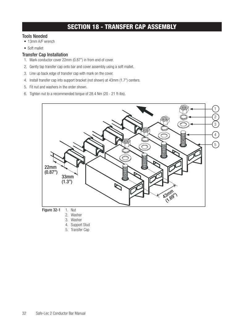
SECTION 18 - TRANSFER CAP ASSEMBLYTools Needed• 13mm A/F wrench
• Soft mallet
Transfer Cap Installation1. Mark conductor cover 22mm (0.87”) in from end of cover.
2. Gently tap transfer cap onto bar and cover assembly using a soft mallet.
3. Line up back edge of transfer cap with mark on the cover.
4. Install transfer cap into support bracket (not shown) at 43mm (1.7”) centers.
5. Fit nut and washers in the order shown.
6. Tighten nut to a recommended torque of 28.4 Nm (20 - 21 ft-lbs).
43mm
(1.69”)
22mm(0.87”)
33mm(1.3”)
SECTION 18 - TRANSFER CAP ASSEMBLY
Figure 32-1 1. Nut2. Washer3. Washer4. Support Stud5. Transfer Cap
1
3
2
4
5

Safe-Lec 2 Conductor Bar Manual 33
Side view of transfer caps showing maximum alignment tolerance.
Plan view of transfer caps showing maximum alignment tolerance.
Please note: Where transfer caps are used in a system, tandem collectors must be used.
SECTION 19 - TRANSFER CAP MOUNTING DETAILS
SECTION 19 - TRANSFER CAP MOUNTING DETAILS

34 Safe-Lec 2 Conductor Bar Manual
SECTION 20 - ASSEMBLY OF ISOLATION SPLICE ASSEMBLIESTools Needed:• 10mm A/F open ended wrench
Installation1. Fit bolt into joint plate. Ensure tab captivates the head on the setscrew.
2. Slide bolt and joint plate into conductor bar ends respectively.
3. Place cap over bolt.
4. Fit washers and nuts in the order shown.
5. Tighten nuts to a recommended value of 8 Nm (5-6 ft-lbs).
Note:Wings on tab toface upwards.
SECTION 20 - ASSEMBLY OF ISOLATION SPLICE ASSEMBLIES
Figure 34-1 1. Nut2. Washer3. Cap4. Bolt5. Joint Plate6. Conductor Bar7. Conductor Bar

Safe-Lec 2 Conductor Bar Manual 35
SECTION 21 - SYSTEM MAINTENANCE AND INSTALLATION NOTES
Maintenance Notes1. Contact shoes should be checked for wear on a monthly basis until a wear pattern can be established.
2. Check alignment of collector and conductor bars. Base of collector should be directly in-line with associated conductor.
3. Check conductor system to ensure no damage to insulation cover.
4. In environments that are subject to considerable build up of dust, especially conductive dust, remove this dust at regular intervals by brushing.
5. Check collector pivot points are free from any contamination.
6. Uneven shoe wear indicates less than optimal collector alignment.
Installation Notes1. Ensure all power is disconnected before attempting to install or maintain the system.
2. Ensure all electrical joints are free from any contamination.
3. Ensure correct alignment and location of support brackets.
4. Ensure conductor joints are not against hanger clamps. Adequate clearance must be allowed for expansion and contraction.
5. Ensure correct alignment of collector with conductor bar. Collector arms should be parallel with contact surface.
6. Ensure all power cables are flexible to allow expansion and contraction of the conductor bar system.
7. Ensure all armored cables are terminated into a suitable junction box and only flexible cables are installed into the powerfeed assemblies.
8. Ensure conductor bars DO NOT support the weight of the feed cables.
9. Conductix-Wampfler recommends that the first accessible conductor bar should be the ground bar.
SECTION 21 - SYSTEM MAINTENANCE AND INSTALLATION NOTES

36 Safe-Lec 2 Conductor Bar Manual
SECTION 22 - DI AND SI COLLECTOR CONTACT SHOE AND SHOE HOLDER
NOTE• Collector contact shoe and shoe holder are supplied as replacement PN XA-310993 for phase collectors and PN XA-399357 for
ground collectors . For Ground Shoes with deflector consult factory.
Tools Needed• Flat Blade Screwdriver
• 7Mm A/F Wrench
Replacement Instructions1. Remove screws to separate shoe halves.
2. Disconnect cables from collector shoe.
3. Replace shoe and torque cable hardware to 31 in-lbs.
4. Ensure shoe seats properly in case halves.
5. Screw case halves together, torque to 9-10 in-lbs.
SECTION 22 - DI AND SI COLLECTOR CONTACT SHOE AND SHOE HOLDER
Replacement of 200 Amp Collector Contact Shoe
5mm

Safe-Lec 2 Conductor Bar Manual 37
SECTION 23 - ASSEMBLY FOR 1, 2, 3, & 4-WAY PICKUP GUIDE Assembly Instructions
1. Remove nut, lock washer, and flat washer.
2. Remove transfer caps from pickup guide.
NOTE• Bracket width must not exceed 40.0mm (1.55”).
3. Fit transfer caps on to the ends of the conductor bars.
4. Ensure any hanger clamps are at least one meter back from the transfer caps.
5. Squeeze transfer caps together and fit pickup guide over support stud.
6. Fit transfer cap support bracket over support stud.
7. Fit nut, lock washer, and flat washer in order shown.
8. Tighten nut to a recommended torque of 28.4 Nm. (20-21 ft-lbs).
9. Remove nut, lock washer, and flat washer.
10. Fit bracket over bolt.
11. Fit nut, lock washer, flat washer.
12. Tighten nut to a recommended torque of 28.4 Nm (20-21 ft-lbs).
SECTION 23 - ASSEMBLY FOR 1, 2, 3, & 4-WAY PICKUP GUIDE
NOTE• Bracket width must not exceed 40.0mm (1.55”).
Figure 37-1 1. Support Stud2. Nut3. Lock Washer4. Flat Washer
5. Bolt6. Nut7. Lock Washer8. Flat Washer
NOTE• When using pick-up guides, you must use collector part
numbers XA-310988 and XA-399358. Please contact factory when ordering.

38 Safe-Lec 2 Conductor Bar Manual
SECTION 25 - CONDUCTOR BAR DE-RATING CHART
SECTION 24 - HANGER CENTERS DIAGRAMS
XA-310821XA-310857
XA-310835XA-310859
43mm(1.69”)
310861310871
43mm(1.69")
XA-310861XA-310871
43 mm
(1.69”)
XA-310882XA-310899
1.6900 [42.93]
XA-310969
43mm MIN
(1.69”)
43mm MIN
(1.69”)
XA-310918XA-310834XA-310824
XA-310829
43mm MIN
(1.69”)
SECTION 24 - HANGER CENTERS DIAGRAMS

Safe-Lec 2 Conductor Bar Manual 39
SECTION 25 - CONDUCTOR BAR DE-RATING CHART
SECTION 25 - CONDUCTOR BAR DE-RATING CHART
Cond
ucto
rs a
re U
L ra
ted
for c
ontin
uous
dut
y. Us
the
appr
opria
te
curv
e on
the
grap
h to
rate
the
cond
ucto
rs fo
r you
r dut
y cy
cle.
Note
: Dut
y cy
cles
are
bas
ed o
n a
2 m
inut
e cy
cle
time.
(
i.e. 5
0% =
1 m
inut
e on
1 m
inut
e of
f.)
300A
100A
160A
200A
250A
85A
3105
01
3104
10
3107
01
3106
01
3103
01
3102
01
3101
01

Safe-Lec 2 Conductor Bar Manual 964200.12
Contact USA for our Global Sales Offices
www.conductix.us
USA / LATIN AMERICA
10102 F Street
Omaha, NE 68127
Customer Support
Phone +1-800-521-4888
Phone +1-402-339-9300
Fax +1-402-339-9627
CANADA
18450 J.A. Bombardier
Mirabel, QC J7J 0H5
Customer Support
Phone +1-800-667-2487
Phone +1-450-565-9900
Fax +1-450-851-8591
MÉXICO
Calle Treviño 983-C
Zona Centro
Apodaca, NL México 66600
Customer Support
Phone (+52 81) 1090 9519
(+52 81) 1090 9025
(+52 81) 1090 9013
Fax (+52 81) 1090 9014
BRAZIL
Rua Luiz Pionti, LT 05, QD.
L - Vila Progresso
Itu, São Paulo, Brasil
CEP: 13.313-534
Customer Support
Phone (+55 11) 4813 7330
Fax (+55 11) 4813 7330
© C
ondu
ctix-
Wam
pfler
| 20
17 |
Subj
ect t
o Te
chni
cal M
odifi
catio
ns W
ithou
t Prio
r Not
ice