Embed Size (px)
DESCRIPTION
ss
Citation preview
IBM System Storage SAN Volume Controller
Software Installation and Configuration Guide - Errata Version 5.1.0 April 14, 2010
SC23-6628-05 Errata
2 SAN Volume Controller Software Installation and Configuration Guide – Errata Apr 14, 2010
Contents
Who should use this guide.........................................................................................................................4 Last Update.................................................................................................................................................4 Change History...........................................................................................................................................4 Chapter 3. SAN fabric and LAN overview .............................................................................................5
iSCSI configuration rules........................................................................................................................5 SSD configuration rules for nodes, I/O groups and clusters..................................................................5 SSD configuration rules for VDisks.......................................................................................................5
Chapter 5. Using the SAN Volume Controller Console ........................................................................6 Configuring the iSNS server address .....................................................................................................6 Configuring cluster iSCSI authentication...............................................................................................6 Adding a mirrored copy to a VDisk .......................................................................................................6
Chapter 6. Using the CLI..........................................................................................................................7 Creating VDisks using the CLI...............................................................................................................7 Adding a copy to a VDisk using the CLI ...............................................................................................8 Collecting SSD dump files using the CLI ..............................................................................................8
Chapter 7. Backing up and restoring the cluster configuration...........................................................9 Restoring the cluster configuration using the CLI .................................................................................9
Chapter 8. Upgrading the SAN Volume Controller software ............................................................12 Upgrading clusters with internal SSD drives .......................................................................................12 Upgrading solid-state drive (SSD) software ........................................................................................13
Chapter 11. Configuring and servicing storage systems .....................................................................13 Configuring EMC Symmetrix and Symmetrix DMX systems ............................................................13 Global settings for IBM System Storage DS5000 or IBM DS4000 systems ......................................14
Configuring the Nexsan SATABeast .....................................................................................................14 Configuring Nexsan SATABeast systems ...........................................................................................14 Supported models of the Nexsan SATABeast system .........................................................................14 Supported firmware levels for the Nexsan SATABeast ......................................................................14 Concurrent maintenance on the Nexsan SATABeast ..........................................................................15 User interfaces on the Nexsan SATABeast..........................................................................................15 Logical unit creation, deletion, and migration for Nexsan SATABeast systems................................15 Sharing the Nexsan SATABeast between a host and the SAN Volume Controller............................16 Quorum disks on the Nexsan SATABeast ...........................................................................................16 Advanced functions for the Nexsan SATABeast.................................................................................16
Configuring the EMC VMAX ................................................................................................................16 Configuring EMC VMAX systems ..................................................... Error! Bookmark not defined. Supported models of the EMC VMAX Controller ..............................................................................16 Supported firmware levels for the EMC VMAX.................................................................................16 Concurrent maintenance on the EMC VMax.......................................................................................16 User interfaces on EMC VMAX ..........................................................................................................17 EMC Control Center .............................................................................................................................17 SYMCLI................................................................................................................................................17 Switch zoning limitations for the EMC VMAX ..................................................................................18 Switch zoning........................................................................................................................................18 Connecting to the SAN .........................................................................................................................18 Quorum disks on EMC VMAX............................................................................................................18 Advanced functions for EMC VMAX .................................................................................................18 LU creation and deletion on EMCVMAX ...........................................................................................18 Meta device ...........................................................................................................................................19 Configuring settings for the EMC VMAX...........................................................................................19
© Copyright International Business Machines Corporation 2010 3
Global settings for the EMC Symmetrix VMAX.................................................................................19 Port settings for the EMC VMAX........................................................................................................20 Logical unit settings for the EMC VMAX...........................................................................................20 Mapping and virtualization settings for the EMC VMAX ..................................................................21 Volume Logix and masking..................................................................................................................21
4 SAN Volume Controller Software Installation and Configuration Guide – Errata Apr 14, 2010
Who should use this guide This errata should be used by anyone using the IBM System Storage SAN Volume Controller Software Installation and Configuration Guide. You should review the errata contained within this guide and note the details with respect to the copy of the Software Installation and Configuration Guide supplied with your SAN Volume Controller.
Last Update This document was last updated: April 14, 2010
Change History The following revisions have been made to this document: Revision Date Sections Modified November 3, 2009 New publication February 11, 2010 SSD configuration rules for nodes, I/O
groups and clusters Global settings for IBM System Storage DS5000 or IBM DS4000 systems
March 21,2010 Configuring the NexSan SATABeast Storage Controller
April 14, 2010 Configuring the EMC VMAX Storage Controller
Table 1: Change History
© Copyright International Business Machines Corporation 2010 5
Chapter 3. SAN fabric and LAN overview The following corrections should be noted.
iSCSI configuration rules Page 91. The following paragraph is incorrect and should be removed.
Each I/O group can map VDisks to the same total maximum number of host objects (256), which could include fibre-channel attachments, iSCSI attachments, or both.
The following information replaces the above paragraph.
See the following Web site for the latest maximum configuration support: www.ibm.com/storage/support/2145
SSD configuration rules for nodes, I/O groups and clusters Page 95. The following bullet points are incorrect and should be removed.
• Do not combine nodes that contain SSDs and nodes that do not contain SSDs in a single I/O group. However, while upgrading an earlier SAN Volume Controller node to a SAN Volume Controller 2145-CF8 node, you can temporarily combine the two node types in a single I/O group.
• Nodes in the same I/O group must share the same number of SSDs.
SSD configuration rules for VDisks Page 95/96. The following additional information is provided.
The synchronization rate must be set such that the VDisk copies will resynchronize quickly after loss of synchronization. Synchronization will be lost if one of the nodes goes offline either during a concurrent code upgrade or because of maintenance. During code upgrade the synchronization must be restored within 30 minutes or the upgrade will stall. Unlike VDisk copies from external storage subsystems, during the period that the SSD VDisk copies are not synchronized access to the VDisk depends on the single node containing the SSD storage associated with the synchronized VDisk copy. The default synchronization rate is typically too low for SSD VDisk mirrors; instead it should be set to 80 or above. Note: To increase the amount of time between the two nodes containing VDisk copies going offline during the normal upgrade process, consider using the User-paced Software upgrade procedure.
6 SAN Volume Controller Software Installation and Configuration Guide – Errata Apr 14, 2010
Chapter 5. Using the SAN Volume Controller Console The following corrections should be noted.
Configuring the iSNS server address Page 149. The following information is misleading and should be removed.
After you configure the iSNS server address for the cluster, you can configure cluster iSCSI authentication. Note: To help in problem determination, this step can be delayed until after the first one or two hosts have been configured and their connectivity has been tested without authentication configured.
Configuring cluster iSCSI authentication Page 149. The following information replaces this section in the original document.
You can use the SAN Volume Controller Console to configure the Challenge-Handshake Authentication Protocol (CHAP) to authenticate the SAN Volume Controller cluster to the iSCSI-attached hosts. After the CHAP secret is set for the cluster, any attached hosts which have target authentication enabled must use this CHAP secret to authenticate. This task assumes that you have already launched the SAN Volume Controller Console. To configure authentication between the SAN Volume Controller cluster to the iSCSI-attached hosts, follow these steps: 1. In the portfolio, click Configure iSCSI Authentication. The Configure Cluster iSCSI Authentication panel is displayed. 2. On the Configure Cluster iSCSI Authentication panel, enter the shared passphrase that is used to authenticate the SAN Volume Controller to the host in the CHAP Authentication Secret field. 3. Click OK. After you configure the CHAP secret for the SAN Volume Controller cluster, ensure that the cluster CHAP secret is added to each iSCSI-attached host which has target authentication enabled.
Adding a mirrored copy to a VDisk Page 164. The following additional information is provided.
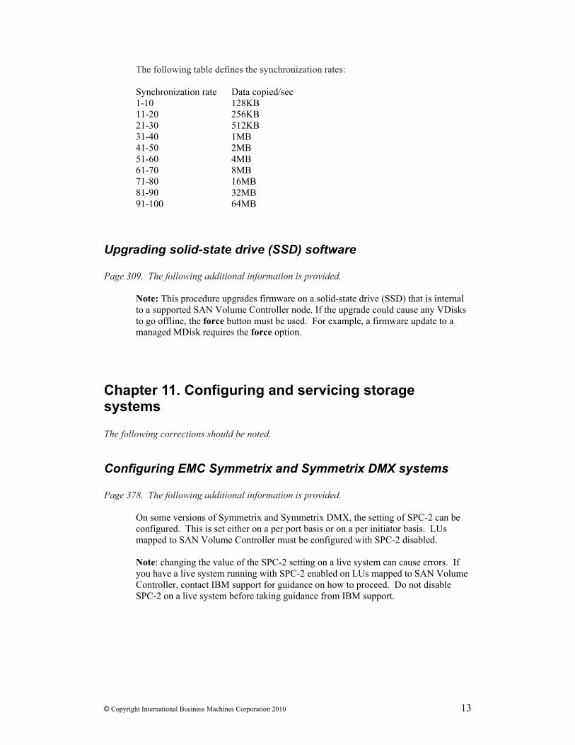
The rate at which the VDisk copies will resynchronise after loss of synchronization can be specified. The following table defines the rates: Synchronization rate Data copied/sec 1-10 128KB 11-20 256KB 21-30 512KB 31-40 1MB
© Copyright International Business Machines Corporation 2010 7
41-50 2MB 51-60 4MB 61-70 8MB 71-80 16MB 81-90 32MB 91-100 64MB The default setting is 50. The synchronization rate must be set such that the VDisk copies will resynchronize quickly after loss of synchronization. In the case of a mirrored VDisk that uses disk extents on a solid-state drive (SSD) that is located on a SAN Volume Controller node, synchronization will be lost if one of the nodes goes offline either during a concurrent code upgrade or because of maintenance. During code upgrade the synchronization must be restored within 30 minutes or the upgrade will stall. Unlike VDisk copies from external storage subsystems, during the period that the SSD VDisk copies are not synchronized access to the VDisk depends on the single node containing the SSD storage associated with the synchronized VDisk copy . The default synchronization rate is typically too low for SSD VDisk mirrors; instead it should be set to 80 or above. Note: To increase the amount of time between the two nodes containing VDisk copies going offline during the normal upgrade process, consider using the User-paced Software upgrade procedure.
Chapter 6. Using the CLI The following corrections should be noted.
Creating VDisks using the CLI Page 242. The following additional information is provided for point 5.
The rate at which the VDisk copies will resynchronise after loss of synchronization can be specified using the syncrate parameter. The following table defines the rates: syncrate value Data copied/sec 1-10 128KB 11-20 256KB 21-30 512KB 31-40 1MB 41-50 2MB 51-60 4MB 61-70 8MB 71-80 16MB 81-90 32MB 91-100 64MB The default setting is 50. The synchronization rate must be set such that the VDisk copies will resynchronize quickly after loss of synchronization.
8 SAN Volume Controller Software Installation and Configuration Guide – Errata Apr 14, 2010
In the case of a mirrored VDisk that uses disk extents on a solid-state drive (SSD) that is located on a SAN Volume Controller node, synchronization will be lost if one of the nodes goes offline either during a concurrent code upgrade or because of maintenance. During code upgrade the synchronization must be restored within 30 minutes or the upgrade will stall. Unlike VDISK copies from external storage subsystems, during the period that the SSD VDisk copies are not synchronized access to the VDisk depends on the single node containing the SSD storage associated with the synchronized VDisk copy . The default synchronization rate is typically too low for SSD VDisk mirrors; instead it should be set to 80 or above. The following is an example of the CLI command that you can issue to create a VDisk with two copies using the I/O group and MDisk group name and specifying the synchronization rate: svctask mkvdisk -iogrp io_grp1 -mdiskgrp grpa:grpb -size 500 -vtype striped -copies 2 –syncrate 90 where io_grp1 is the name of the I/O group that you want the VDisk to use, grpa is the name of the MDisk group for the primary copy of the VDisk and grpb is the name of the MDisk group for the second copy of the VDisk, and 2 is the number of VDisk copies and the synchronization rate is 90 which is equivalent to 32MB per second.
Adding a copy to a VDisk using the CLI Page 243. The following additional information is provided
The rate at which the VDisk copies will resynchronise after loss of synchronization can be specified using the syncrate parameter. See the Creating VDisks topic for a description of this parameter.
Collecting SSD dump files using the CLI Page 238. The following information replaces this section in the original document.
You can use the command-line interface (CLI) to collect dump files from solid-state drives (SSDs). To collect internal log files from solid-state drive (SSD) MDisks, run the triggermdiskdump command. Subsequently, you can list, delete or copy the dump files. The triggermdiskdump command generates a dump file and saves it in the /dumps/mdisk directory on the node that contains the SSD. 1. Issue the svctask triggermdiskdump CLI command. The following example shows the CLI format for generating a dump file for the specified SSD MDisk: svctask triggermdiskdump mdisk_id | mdisk_name 2. Issue the svcinfo lsmdiskdumps command to list files in the /dumps/mdisk directory on the specified node. The following example shows the CLI format for listing the dump files for the specified node:
© Copyright International Business Machines Corporation 2010 9
svcinfo lsmdiskdumps node_id | node_name 3. Issue the svctask cleardumps command to delete all files from the /dumps directory and all subdirectories on the specified node. To delete files from a subdirectory of /dumps only, specify the -prefix parameter. The following example shows the CLI format for deleting all dump files from the specified node: svctask cleardumps node_id | node_name The following example shows the CLI format for deleting only the dump files in the specified /elogs/ directory: svctask cleardumps -prefix "/dumps/elogs/*" 4. Issue the svctask cpdumps command to copy dump files to the configuration node. If the /dumps directory on the configuration node becomes full before the copy completes, no message is returned. To avoid this scenario, clear the /dumps directory after migrating data from the configuration node. The following example shows the CLI format for copying all dump files from the specified node to the configuration node: svctask cpdumps -prefix /dumps node_id | node_name
Chapter 7. Backing up and restoring the cluster configuration The following corrections should be noted.
Restoring the cluster configuration using the CLI Page 299. The following information replaces this section in the original document. Steps 6 and 7 have been modified. Step 13 has been added.
You can restore your cluster configuration data using the command-line interface (CLI). Important: There are two phases during the restore process: prepare and execute. You must not make any changes to the fabric or cluster between these two phases. Complete the following steps to restore your cluster configuration data: 1. Select delete cluster from the front panel on each node in the cluster that does not display Cluster : on the front panel. If the front panel of the node displays Cluster :, the node is already a candidate node. 2. Create a new cluster from the front panel of any node in the cluster. If possible, use the node that was originally the configuration node for the cluster. 3. Generate an SSH key pair for all of the hosts to use to access the CLI. 4. Start the SAN Volume Controller Console. 5. On the Viewing Clusters panel, select the cluster that you are recovering from the list, select Remove the Cluster from the task list and click Go. The Remove Cluster
10 SAN Volume Controller Software Installation and Configuration Guide – Errata Apr 14, 2010
panel displays. Click Yes to confirm the removal of the cluster. The Viewing Cluster panel displays. 6. On the Viewing Cluster panel, select Add a Cluster from the task list and click Go. The Adding a Cluster panel displays. From this panel, you need to initialise the new cluster by completing these steps: a. Enter the IP address for the cluster that you are recovering. Select Create (Initialize) Cluster. Click OK. b. The Sign on to Cluster panel appears. On this panel, enter superuser and the initial password when the cluster had been created in step 2. c. Configure the new cluster with required settings as described in Chapter 5. 7. To work with the command-line interface to finish restoring the cluster, you also need to assign an SSH key to the user that has Security Administrator role on the cluster by completing these steps: a. On the Viewing Cluster panel, select the new cluster and select Launch SAN Volume Controller Console from the task list and click Go. b. Click Manage Authentication → Users in the portfolio. The Modifying User superuser panel is displayed. c. To optionally modify the password, enter a new password in the New Password field. In the Re-Enter New Password field, re-type the new password. d. To assign the SSH key that you generated in Step 3 to the user, enter the name of SSH key file in the SSH Key Public File field or click Browse to select the file. e. Click OK. 8. Using the command-line interface, issue the following command to log onto the cluster: ssh -l admin your_cluster_name -p 22 Where your_cluster_name is the name of the cluster for which you want to restore the cluster configuration. Note: Because the RSA host key has changed, a warning message displays when connecting to the cluster using SSH. 9. Issue the following CLI command to ensure that only the configuration node is online: svcinfo lsnode The following is an example of the output that is displayed: id name status IO_group_id IO_group_name config_node 1 node1 online 0 io_grp0 yes 10. Verify that the most recent version of your /tmp/svc.config.backup.xml configuration file has been copied to your SSPC. The most recent file is located on your configuration node in the /tmp or /dumps directory. In addition, a /dumps/svc.config.cron.xml_node_name configuration file is created daily on the configuration node. In certain cases, you might prefer to copy an earlier configuration file. If necessary, back up your configuration file as described in “Backing up the cluster configuration using the CLI” on page 297. 11. Issue the following CLI command to remove all of the existing backup and restore cluster configuration files that are located on your configuration node in the /tmp directory: svcconfig clear -all 12. Copy the svc.config.backup.xml file from the IBM System Storage Productivity Center or master console to the /tmp directory of the cluster using the PuTTY pscp
© Copyright International Business Machines Corporation 2010 11
program. Perform the following steps to use the PuTTY pscp program to copy the file: a. Open a command prompt from the IBM System Storage Productivity Center or master console. b. Set the path in the command line to use pscp with the following format: set PATH=C:\path\to\putty\directory;%PATH% c. Issue the following command to specify the location of your private SSH key for authentication: pscp <private key location> source [source] [user@]host:target 13. If the cluster contains any SAN Volume Controller 2145-CF8 nodes with internal Solid State Disks, then these nodes must be added to the cluster now. In order to do this, determine the panelname, name and I/O groups of any such nodes from the configuration backup file. To add the nodes to the cluster, issue this command: source svctask addnode –panelname <panelname> -iogrp <iogrp name/id> -name <node name> 14. Issuing the following CLI command to compare the current cluster configuration with the backup configuration data file: svcconfig restore -prepare This CLI command creates a log file in the /tmp directory of the configuration node. The name of the log file is svc.config.restore.prepare.log. Note: It can take up to a minute for each 256-MDisk batch to be discovered. If you receive error message CMMVC6119E for an MDisk after you enter this command, all the managed disks (MDisks) might not have been discovered yet. Allow a suitable time to elapse and try the svcconfig restore -prepare command again. 15. Issue the following command to copy the log file to another server that is accessible to the cluster: pscp -i <private key location> [user@]host:source target 16. Open the log file from the server where the copy is now stored. 17. Check the log file for errors. • If there are errors, correct the condition which caused the errors and reissue the
command. You must correct all errors before you can proceed to step 17. • If you need assistance, contact the IBM Support Center. 18. Issue the following CLI command to restore the cluster configuration: svcconfig restore -execute Note: Issuing this CLI command on a single node cluster adds the other nodes and hosts to the cluster. This CLI command creates a log file in the /tmp directory of the configuration node. The name of the log file is svc.config.restore.execute.log. 19. Issue the following command to copy the log file to another server that is accessible to the cluster: pscp -i <private key location> [user@]host:source target 20. Open the log file from the server where the copy is now stored. 21. Check the log file to ensure that no errors or warnings have occurred. Note: You might receive a warning that states that a licensed feature is not enabled. This means that after the recovery process, the current license settings do not match
12 SAN Volume Controller Software Installation and Configuration Guide – Errata Apr 14, 2010
the previous license settings. The recovery process continues normally and you can enter the correct license settings in the SAN Volume Controller Console at a later time. The following output is displayed after a successful cluster configuration restore operation: IBM_2145:your_cluster_name:admin> 22. After the cluster configuration is restored, verify that the quorum disks are restored to the MDisks that you want by using svcinfo lsquorum command. To restore the quorum disks to the correct MDisks, issue the appropriate svctask setquorum CLI commands. You can remove any unwanted configuration backup and restore files from the /tmp directory on your configuration by issuing the svcconfig clear -all CLI command. Note: The recovery process does not recreate the superuser password and SSH keys. Ensure those are recreated before managing the recovered cluster.
Chapter 8. Upgrading the SAN Volume Controller software The following corrections should be noted.
Upgrading clusters with internal SSD drives Page 303/304. The following additional information is provided.
The SAN Volume Controller upgrade process reboots each node in the cluster in turn. Before the upgrade commences and before each node is upgraded, the upgrade process checks for dependent VDisks. Dependent VDisks can occur on nodes with internal SSDs drives if a VDisk has been recently created or a copy of the VDisk has been offline recently so the node has the only up-to-date copy of the data.
The upgrade process takes each node offline temporarily to perform the upgrade. While the node containing an internal SSD is offline, any data written to VDisks with a mirrored copy on the offline node will only be written to the other online copy. Once the upgraded node rejoins the cluster, data will be resynchronized from the copy that remained online. The upgrade process will delay approximately 30 minutes before starting the upgrade on the partner node, the synchronization must complete within this time or the upgrade will stall and require manual intervention. Any mirrored VDisk that uses disk extents on a solid-state drive (SSD) that is located on a SAN Volume Controller node for one or both of its VDisk copies should have its synchronization rate set to 80 or above to ensure that the resynchronization completes in time. Note: To increase the amount of time between the two nodes containing VDisk copies going offline during the normal upgrade process, consider using the User-paced Software upgrade procedure.
© Copyright International Business Machines Corporation 2010 13
The following table defines the synchronization rates: Synchronization rate Data copied/sec 1-10 128KB 11-20 256KB 21-30 512KB 31-40 1MB 41-50 2MB 51-60 4MB 61-70 8MB 71-80 16MB 81-90 32MB 91-100 64MB
Upgrading solid-state drive (SSD) software Page 309. The following additional information is provided.
Note: This procedure upgrades firmware on a solid-state drive (SSD) that is internal to a supported SAN Volume Controller node. If the upgrade could cause any VDisks to go offline, the force button must be used. For example, a firmware update to a managed MDisk requires the force option.
Chapter 11. Configuring and servicing storage systems The following corrections should be noted.
Configuring EMC Symmetrix and Symmetrix DMX systems Page 378. The following additional information is provided.
On some versions of Symmetrix and Symmetrix DMX, the setting of SPC-2 can be configured. This is set either on a per port basis or on a per initiator basis. LUs mapped to SAN Volume Controller must be configured with SPC-2 disabled. Note: changing the value of the SPC-2 setting on a live system can cause errors. If you have a live system running with SPC-2 enabled on LUs mapped to SAN Volume Controller, contact IBM support for guidance on how to proceed. Do not disable SPC-2 on a live system before taking guidance from IBM support.
14 SAN Volume Controller Software Installation and Configuration Guide – Errata Apr 14, 2010
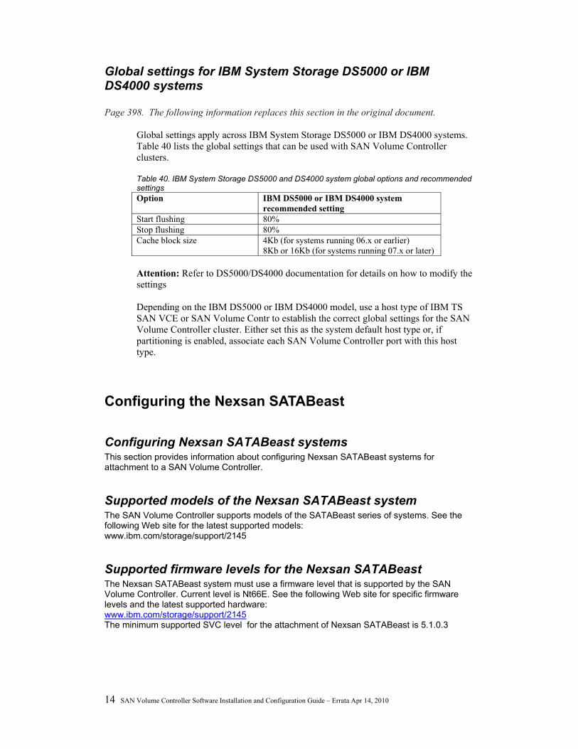
Global settings for IBM System Storage DS5000 or IBM DS4000 systems Page 398. The following information replaces this section in the original document.
Global settings apply across IBM System Storage DS5000 or IBM DS4000 systems. Table 40 lists the global settings that can be used with SAN Volume Controller clusters. Table 40. IBM System Storage DS5000 and DS4000 system global options and recommended settings Option IBM DS5000 or IBM DS4000 system
recommended setting Start flushing 80% Stop flushing 80% Cache block size 4Kb (for systems running 06.x or earlier)
8Kb or 16Kb (for systems running 07.x or later) Attention: Refer to DS5000/DS4000 documentation for details on how to modify the settings Depending on the IBM DS5000 or IBM DS4000 model, use a host type of IBM TS SAN VCE or SAN Volume Contr to establish the correct global settings for the SAN Volume Controller cluster. Either set this as the system default host type or, if partitioning is enabled, associate each SAN Volume Controller port with this host type.
Configuring the Nexsan SATABeast
Configuring Nexsan SATABeast systems This section provides information about configuring Nexsan SATABeast systems for attachment to a SAN Volume Controller.
Supported models of the Nexsan SATABeast system The SAN Volume Controller supports models of the SATABeast series of systems. See the following Web site for the latest supported models: www.ibm.com/storage/support/2145
Supported firmware levels for the Nexsan SATABeast The Nexsan SATABeast system must use a firmware level that is supported by the SAN Volume Controller. Current level is Nt66E. See the following Web site for specific firmware levels and the latest supported hardware: www.ibm.com/storage/support/2145 The minimum supported SVC level for the attachment of Nexsan SATABeast is 5.1.0.3
© Copyright International Business Machines Corporation 2010 15
Concurrent maintenance on the Nexsan SATABeast Concurrent maintenance is the capability to perform I/O operations to an Nexsan SATABeast while simultaneously performing maintenance operations on it. You can perform nondisruptive maintenance procedures concurrently on the following components: • Nexsan SATABeast controller • Disk drive
User interfaces on the Nexsan SATABeast NexScan® is the Nexsan's WEB enabled GUI (Graphical User Interface). NexScan provides access to your SATABeast system from any standard internet browser or from any host computer either directly connected or via a LAN or WAN. NexScan is platform independent. No software or patches are required. RS232 Serial Interface DB9 (one per controller) - Supports VT100 - Compatible with terminal emulation software, such as Hyper Terminal and Kermit.
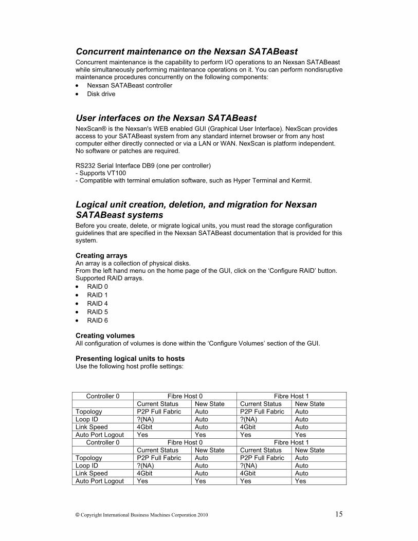
Logical unit creation, deletion, and migration for Nexsan SATABeast systems Before you create, delete, or migrate logical units, you must read the storage configuration guidelines that are specified in the Nexsan SATABeast documentation that is provided for this system. Creating arrays An array is a collection of physical disks. From the left hand menu on the home page of the GUI, click on the ‘Configure RAID’ button. Supported RAID arrays. • RAID 0 • RAID 1 • RAID 4 • RAID 5 • RAID 6 Creating volumes All configuration of volumes is done within the ‘Configure Volumes’ section of the GUI. Presenting logical units to hosts Use the following host profile settings:
Controller 0 Fibre Host 0 Fibre Host 1 Current Status New State Current Status New State Topology P2P Full Fabric Auto P2P Full Fabric Auto Loop ID ?(NA) Auto ?(NA) Auto Link Speed 4Gbit Auto 4Gbit Auto Auto Port Logout Yes Yes Yes Yes
Controller 0 Fibre Host 0 Fibre Host 1 Current Status New State Current Status New State Topology P2P Full Fabric Auto P2P Full Fabric Auto Loop ID ?(NA) Auto ?(NA) Auto Link Speed 4Gbit Auto 4Gbit Auto Auto Port Logout Yes Yes Yes Yes
16 SAN Volume Controller Software Installation and Configuration Guide – Errata Apr 14, 2010
Migrating logical units You can use the standard migration procedure to migrate logical units from the Nexsan SATABeast to the SAN Volume Controller cluster: .
Sharing the Nexsan SATABeast between a host and the SAN Volume Controller You must configure your environment so that only the SAN Volume Controller can access all logical units on the Nexsan SATABeast. You can zone other hosts to communicate with the Nexsan SATABeast for in-band configuration, but nothing else.
Quorum disks on the Nexsan SATABeast The SAN Volume Controller can use logical units (LUs) that are exported by the Nexsan SATABeast as quorum disks. Advanced functions for the Nexsan SATABeast Nexsan advanced functions are not supported with SAN Volume Controller.
Configuring the EMC VMAX Note: VMAX settings provided in this chapter must be applied prior to configuring SVC LUNS
Supported models of the EMC VMAX Controller The SAN Volume Controller supports models of the EMC VMAX Controller See the following Web site for the latest supported models: www.ibm.com/storage/support/2145
Supported firmware levels for the EMC VMAX The EMC VMAX system must use a firmware level that is supported by the SAN Volume Controller. See the following Web site for specific firmware levels and the latest supported hardware: www.ibm.com/storage/support/2145 The minimum supported SVC level for the attachment of EMC VMAX is 4.3.1
Concurrent maintenance on the EMC VMax Concurrent maintenance is the capability to perform I/O operations to the EMC VMAX while simultaneously performing maintenance operations on it. Important: Service actions and upgrade procedures can only be performed by an EMC Field Engineer. The EMC VMAX is an Enterprise class devices that support nondisruptive replacement of the following components:
• Channel Director • Disk Director
© Copyright International Business Machines Corporation 2010 17
• Cache card • Disk drive • Cooling fan • Comms card • EPO card • Operator panel • PSU • Service Processor • Batteries • Ethernet hub
The SAN Volume Controller and EMC VMAX support concurrent upgrade of the EMC VMAX firmware.
User interfaces on EMC VMAX Ensure that you are familiar with the user interface applications that support the EMC VMAX systems.
EMC Control Center A basic EMC VMAX configuration is performed by an EMC Field Engineer (FE) using the EMC VMAX service processor. After the initial configuration, you can configure and control the exported storage. The FE defines the storage device types and sets the configurable options. You can configure and control the exported storage as described below. You can use the EMC Control Center to manage and monitor the EMC VMAX systems. You can use Volume Logix for volume configuration management. Volume Logix allows you to control access rights to the storage when multiple hosts share target ports.
SYMCLI The EMC Symmetrix Command Line Interface (SYMCLI) allows the server to monitor and control the EMC VMAX Sharing the EMC VMAX system between a host and a SAN Volume Controller cluster There are restrictions for sharing EMC VMAX systems between a host and a SAN Volume Controller cluster. An EMC VMAX system can be shared between a host and a SAN Volume Controller under the following conditions: v When possible, avoid sharing target ports between the SAN Volume Controller cluster and other hosts. If this cannot be avoided, you must regularly check the combined I/O workload that is generated by the SAN Volume Controller cluster and the other hosts. The performance of either the SAN Volume Controller cluster or the hosts is impacted if the workload exceeds the target port capabilities. v A single host must not be connected to a SAN Volume Controller and an EMC VMAX because the multipathing drivers (for example, subsystem device driver (SDD) and PowerPath) cannot coexist. v If the EMC VMAX is configured in such a way that other hosts cannot access the LUs that are managed by the SAN Volume Controller cluster, other hosts can be directly connected to an EMC VMAX system at the same time as a SAN Volume Controller
18 SAN Volume Controller Software Installation and Configuration Guide – Errata Apr 14, 2010
Switch zoning limitations for the EMC VMAX There are limitations in switch zoning for the SAN Volume Controller and the EMC VMAX systems.
Switch zoning The SAN Volume Controller switch zone must include at least one target port on two or more fibre-channel adapters to avoid a single point of failure. The EMC VMAX must be configured to present logical units (LUs) to all SAN Volume Controller initiator ports that are in the fabric zone. Only SAN Volume Controller initiator ports that are LUN masked on the EMC VMAX controller should be present in the fabric zone. Note: The EMC VMAX systems present themselves to a SAN Volume Controller cluster as separate controllers for each port zoned to the SAN Volume Controller. For example, if one of these storage systems has 4 ports zoned to the SAN Volume Controller, each port appears as a separate controller rather than one controller with 4 WWPNs. In addition, a given logical unit (LU) must be mapped to the SAN Volume Controller through all controller ports zoned to the SAN Volume Controller using the same logical unit number (LUN).
Connecting to the SAN You can connect a maximum of 16 EMC VMAX ports to the SAN Volume Controller cluster. There are no further special zoning requirements. Configurations that are setup to adhere to the requirements that are described in previous SAN Volume Controller releases are also supported, but should not be followed for new installations.
Quorum disks on EMC VMAX The SAN Volume Controller chooses managed disks (MDisks) that are presented by the EMC VMAX as quorum disks. The SAN Volume Controller uses a logical unit (LU) that is presented by an EMC VMAX as a quorum disk. The SAN Volume Controller provides a quorum disk even if the connection is through a single port.
Advanced functions for EMC VMAX SAN Volume Controller cache-disabled virtual disks (VDisks) can be used as the source or target in VMAX advanced copy functions (for example, SRDF and TimeFinder).
LU creation and deletion on EMCVMAX A logical unit (LU) that is exported by an EMC VMAX, meaning it is visible to a host, is either a Symmetrix device or a Meta device. VMAX device Restriction: An LU with a capacity of 64 MB or less is ignored by the SAN Volume Controller. Symmetrix device is an EMC term for an LU that is hosted by an EMC VMAX. These are all emulated devices and have exactly the same characteristics. The following are the characteristics of a Symmetrix device: v N cylinders v 15 tracks per cylinder v 64 logical blocks per track v 512 bytes per logical block Symmetrix devices can be created using the create dev command from the EMC Symmetrix Command Line Interface (SYMCLI). The configuration of an LU can be changed using the convert dev command from the SYMCLI. Each physical storage device in an EMC Symmetrix is partitioned into 1 to 128 hyper-volumes (hypers). Each hyper can be up to 16 GB. A Symmetrix device maps to one or more hypers, depending on how it is configured. The following are examples of hyper configurations:
© Copyright International Business Machines Corporation 2010 19
• Hypers can be mirrored (2-way, 3-way, 4-way) • Hypers can be formed into RAID-S groups
Meta device Meta device is an EMC term for a concatenated chain of EMC Symmetrix devices. This enables the EMC VMAX to provide LUs that are larger than a hyper. Up to 255 hypers can be concatenated to form a single meta device. Meta devices can be created using the form meta and add dev commands from the SYMCLI. This allows an extremely large LU to be created, however, if exported to the SAN Volume Controller, only the first 2 TB is used. Do not extend or reduce meta devices that are used for managed disks (MDisks). Reconfiguration of a meta device that is used for an MDisk causes unrecoverable data-corruption.
Configuring settings for the EMC VMAX A number of settings and options are available through the EMC VMAX configuration interface. The settings and options can have a scope of the following: v System v Port v Logical unit (LU)
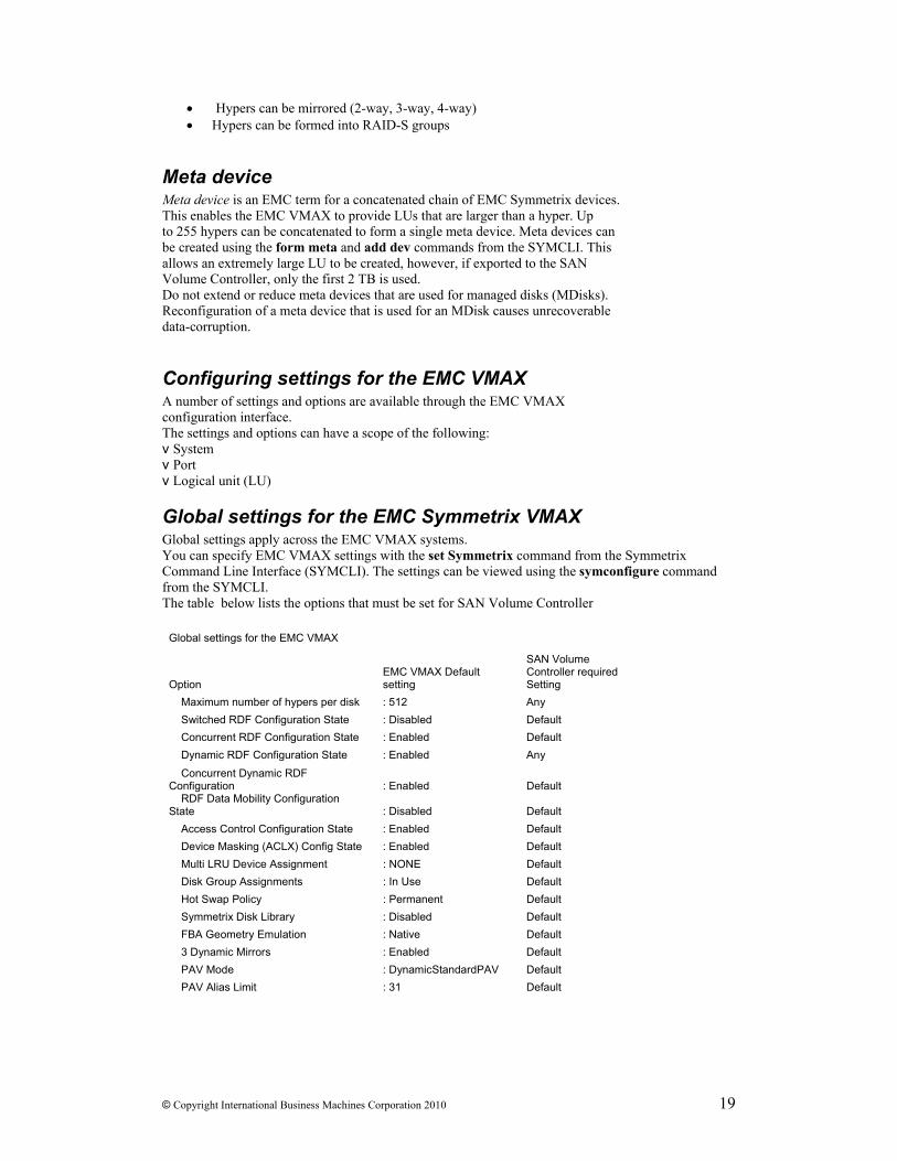
Global settings for the EMC Symmetrix VMAX Global settings apply across the EMC VMAX systems. You can specify EMC VMAX settings with the set Symmetrix command from the Symmetrix Command Line Interface (SYMCLI). The settings can be viewed using the symconfigure command from the SYMCLI. The table below lists the options that must be set for SAN Volume Controller
Global settings for the EMC VMAX
Option EMC VMAX Default setting
SAN Volume Controller required Setting
Maximum number of hypers per disk : 512 Any Switched RDF Configuration State : Disabled Default Concurrent RDF Configuration State : Enabled Default Dynamic RDF Configuration State : Enabled Any Concurrent Dynamic RDF Configuration : Enabled Default RDF Data Mobility Configuration State : Disabled Default Access Control Configuration State : Enabled Default Device Masking (ACLX) Config State : Enabled Default Multi LRU Device Assignment : NONE Default Disk Group Assignments : In Use Default Hot Swap Policy : Permanent Default Symmetrix Disk Library : Disabled Default FBA Geometry Emulation : Native Default 3 Dynamic Mirrors : Enabled Default PAV Mode : DynamicStandardPAV Default PAV Alias Limit : 31 Default
20 SAN Volume Controller Software Installation and Configuration Guide – Errata Apr 14, 2010
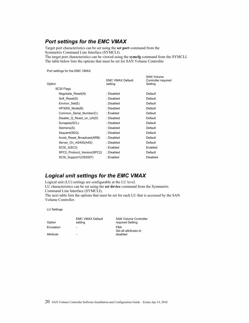
Port settings for the EMC VMAX Target port characteristics can be set using the set port command from the Symmetrix Command Line Interface (SYMCLI). The target port characteristics can be viewed using the symcfg command from the SYMCLI. The table below lists the options that must be set for SAN Volume Controller
Port settings for the EMC VMAX
Option EMC VMAX Default setting
SAN Volume Controller required Setting
SCSI Flags Negotiate_Reset(N) : Disabled Default Soft_Reset(S) : Disabled Default Environ_Set(E) : Disabled Default HP3000_Mode(B) : Disabled Default Common_Serial_Number(C) : Enabled Default Disable_Q_Reset_on_UA(D) : Disabled Default Sunapee(SCL) : Disabled Default Siemens(S) : Disabled Default Sequent(SEQ) : Disabled Default Avoid_Reset_Broadcast(ARB) : Disabled Default Server_On_AS400(A4S) : Disabled Default SCSI_3(SC3) : Enabled Enabled SPC2_Protocol_Version(SPC2) : Disabled Default SCSI_Support1(OS2007) : Enabled Disabled
Logical unit settings for the EMC VMAX Logical unit (LU) settings are configurable at the LU level. LU characteristics can be set using the set device command from the Symmetrix Command Line Interface (SYMCLI). The next table lists the options that must be set for each LU that is accessed by the SAN Volume Controller.
LU Settings
Option EMC VMAX Default setting
SAN Volume Controller required Setting
Emulation - FBA
Attribute - Set all attributes to disabled
© Copyright International Business Machines Corporation 2010 21
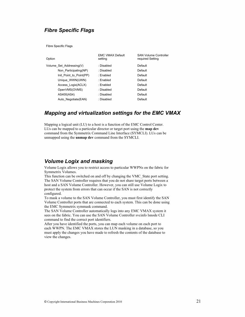
Fibre Specific Flags
Fibre Specific Flags
Option EMC VMAX Default setting
SAN Volume Controller required Setting
Volume_Set_Addressing(V) : Disabled Default Non_Participating(NP) : Disabled Default Init_Point_to_Point(PP) : Enabled Default Unique_WWN(UWN) : Enabled Default Access_Logix(ACLX) : Enabled Default OpenVMS(OVMS) : Disabled Default AS400(AS4) : Disabled Default Auto_Negotiate(EAN) : Disabled Default
Mapping and virtualization settings for the EMC VMAX Mapping a logical unit (LU) to a host is a function of the EMC Control Center. LUs can be mapped to a particular director or target port using the map dev command from the Symmetrix Command Line Interface (SYMCLI). LUs can be unmapped using the unmap dev command from the SYMCLI.
Volume Logix and masking Volume Logix allows you to restrict access to particular WWPNs on the fabric for Symmetrix Volumes. This function can be switched on and off by changing the VMC_State port setting. The SAN Volume Controller requires that you do not share target ports between a host and a SAN Volume Controller. However, you can still use Volume Logix to protect the system from errors that can occur if the SAN is not correctly configured. To mask a volume to the SAN Volume Controller, you must first identify the SAN Volume Controller ports that are connected to each system. This can be done using the EMC Symmetrix symmask command. The SAN Volume Controller automatically logs into any EMC VMAX system it sees on the fabric. You can use the SAN Volume Controller svcinfo lsnode CLI command to find the correct port identifiers. After you have identified the ports, you can map each volume on each port to each WWPN. The EMC VMAX stores the LUN masking in a database, so you must apply the changes you have made to refresh the contents of the database to view the changes.

![Rachmaninov 3rd Piano Concerto [First Movement] · PDF file53-g e5 = 5 !5 = 5 5 5 5 5 4 5 5 =5 5 = 5e5 5 5 5 5 5 5 5e5 5 5!55 5 5 5 5 5e5 5 5 5 5 5 5! 5 $3e55 5 5: 5 5 5 55 5e 55 5](https://img.pdfslide.net/doc/110x75/5a78944a7f8b9a1f128d15db/rachmaninov-3rd-piano-concerto-first-movement-53-g-e5-5-5-5-5-5-5-5-4-5.jpg)