Embed Size (px)
Citation preview

Hea
t re
cove
ry u
nits
CA
DB
/T-D
Heat recovery units housed in galvanised steel
boxes, white plastic coated, with a 25 mm
thick double wall, class M0 fire proof thermal
and acoustic insulation, configurable inlets and
outlets, versions for horizontal installation and for
vertical installation, intakes with a hermetic seal,
F7 filter for inlet air and G4 filter for air extraction.
With two double inlet centrifugal fans with built-
in motor.
CADB/T-D DP25 F7 Series
Heat recovery without additional heat added.
CADB/T-DI DP25 F7 Series
Heat recoveries with a heating resistance.
CADB/T-DC DP25 F7 Series
Heat recoveries with a built-in hot water coil.
Motors
IP20, Class F (ranges 05, 08, 18 and 30).
IP55, class F (ranges 45 and 56).
Additional information
Single phase (CADB) and three phase models
(CADT).
Flows from 450 to 5,600 m3/h.
Versions with an electronic microprocessor
(BASIC, PROGRAM, ADVANZ or DOMO) that
enables the fan speed to be controlled.
The versions with an electronic microprocessor
in sizes 45 and 56 also incorporate a variable
frequency drive.
Horizontal and vertical versions, both with the
possibility of a by-pass.
All side panels are interchangeable, which
makes it possible to directly position the intake
and outtake connections on site.
CONFIGURABLE CROss-FLOw hEAt RECOVERY
CADB/T-D DP25 F7 SeriesCADB/T-DI DP25 F7CADB/T-DC DP25 F7
Stores Offices Cafes, bars and restaurants
IMPORTANT UPDATE TO THE RANGE
New standard configuration with a 25 mm thick
double wall and F7 filters with low loss of load,
manufactured in polypropylene, for inlet air and G4
manufactured in fibreglass for extraction.
A P P L I C A T I O N S
Collectiveventilationdwellings

Hea
t re
cove
ry u
nits
CA
DB
/T-D
Pressure sockets
Pressure sockets before for
clogging filter control.
External weatherproofterminal box
IP55 terminal box located on
the outside of the heat reco-
very casing for easy wiring
access.
BASIC
ADVANZ
PROGRAM
DOMO
Condensationdrain
Drain pipe to evacuate water
from condensation.
Robust construction
High quality finishing with
aluminium profile structure,
providing a robust assembly.
2 high-efficiency filters
2 filters:
F7 filter for inlet air (filtration
efficiency: >80%).
G4 filter for extracted air (effi-
ciency: >90%).
Airtight connectors
Inlet and discharge circular
duct connection flanges with
integrated rubber air seal.
Vertical construction
Specific models for vertical
installation.
Low noise level
Internally lined with 25 mm M0
fire resistant acoustic
insulation.
Easy to mount
Single phase models integrated
hanging supports to install the
heat recovery unit.
Version with by pass
Versions with by pass enabling
100% of the air to by pass the
heat recovery (65% in single-
phase versions).
The by-pass works with a remo-
tely activated servomotor with a
manual switch (not included).
structural Advantages
Versions CADB-D/DC/DI Regulation with an electronic microprocessor
Versions that incorporate an electronic microprocessor (BASIC,
PROGRAM, ADVANZ or DOMO) that enables fan speed control.
The versions with an electronic microprocessor in sizes 45 and 56 also
incorporate a variable frequency drive.

Hea
t re
cove
ry u
nits
CA
DB
/T-D
Versatile assembly
The design of these heat recovery units makes it possible for the user to configure them on site. All side panels are interchangeable, which makes it possible to directly position
the intake and outtake connections on site depending on the specific requirements.
All side panels areinterchangeable
structural Advantages

Hea
t re
cove
ry u
nits
CA
DB
/T-D
Easy maintenance
Models CADB- 05 / 08 / 18 / 30: Rapid access to the filters from the bottom and sides. Easy access for cleaning the heat recovery from the bottom.
Models CADT-45 and CADT-56: Rapid access to the filters from the top. It is also possible to access from the side and
bottom.
Easy access for cleaning the heat recovery from the top.
Reference
C A D B D I H3 0 A T R I-
1 - CADB / CADT: Series
2 - D: Standard range
DI: Range with resistance incorporated
DC:Range with water coil incorporated
3 - Size
4 - A, B, C, D, E, G, H: Type of configuration
5 - H: Horizontal unit
V: Upright unit.
6 - MONO: Monophase support resistance.
TRI: Three phase support resistance
7 - BP: Version with by pass incorporated
8 - DP: Range with double wall insulation
(25 mm).
9 - F7: Air inlet filter F7.
10 - BASIC, PROGRAM, ADVANZ,
DOMO Control.
11 - Configuration control
VAV - Variable airflow
CAV - Constant airfflow (sizes 45 and 56)
(Not posible with BASIC)
COP - Constant pressure (sizes 45 and 56)
(Not possible with BASIC)
B P
1 2 3 4 5 6 7 8 9 10 11
D P 2 5 F 7
structural Advantages
B A S I C V A V

Hea
t re
cove
ry u
nits
CA
DB
/T-D
Versions with an electronic microprocesor: Models and functions
BASIC PROGRAM ADVANZ DOMO
Manual fan speed selection: OFF + 3 speed
Manual fan speed selection: OFF + control of speed range [MIN-MAX] (alternative to 1 )
Imbalance between impulsion and extraction flow only for VAV versions with double inverter (does not apply to 3 speed versions)
Automatic control of fan speed: CO2, CO2/VOC and HR sensors with programmable PPM or HR range (by the installer); available for 3 speed versions and variable speed versions
Remote function of the fan speed signal is 0-10V (alternative to 4 )
Booster via remote NC contact at a pre-set time. Time can be altered by software
Remote "Boost" management by NC contact or proximity sensor (alternative to 6 and 8 )
Unit can be switched ON/OFF via remote switch (alternative to 6 or 7 )
Weekly programs
Prevention of icing of the heat exchanger (simple strategy): blower fan moves to low/off; Setting the extractor fan to maximum speed.
Prevention of build-up of frost in the heat exchanger: proportional mode management with pre-heating coils (alternative to 10 or 12 )
Exchanger frost prevention: Personalized funcions (through a switch NO-NC (alternative to 10 and 11 )
Management of electric post-heating (simple or double stage) in ON/OFF mode. The objec-tive is to attain the average internal temperature value (Tr)
Management of electric post-heating in proportional mode. The objective is to attain the average internal temperature value (Tr) and to keep the impelled air within a set range (Ti)
Management of water coil post-heating in ON/OFF mode. The objective is to attain the aver-age internal temperature value (Tr)
Management of water coil post-heating. The objective is to attain the average internal tem-perature value (Tr) and to keep the impelled air within a set range (Ti)
Management of post-cooling in proportional mode. The objective is to attain the average internal temperature value (Tr) and to keep the impelled air within a set range (Ti)
Remote signalling of the status of the unit via a volt free contact: closed contact=the unit is operating; open contact=the unit is stopped (alternative to 12 )
Monitoring of the state of the filters via period of operation of the equipment or via differen-tial pressure sensors
Monitoring of the state of the fans via a tachometric signal (if supported by the fan) or via differential pressure sensors
1
2
3
4
5
6
7
8
9
10
11
12
13
14
15
16
17
18
19
20
3 3 3 3
3 3 3
3 3 3
3 3 3
3 3
3 3
3 3
3 3
3 3 3
3 3 3 3
3 3
3 3
3
3 3
3
3 3
3 3
3 3
3 3 3 3
3 3 3 3

Hea
t re
cove
ry u
nits
CA
DB
/T-D
Electronic microprocessors BAsIC model - Features and functions
BASIC CONTROL CADB/T-DPRINCIPAL FEATURESTerminal cabinet includes:• Proximity sensor l
• Integrated circuit card and terminal box l
Remote control unit (100 m max.) l
Ready-mounted, ready-wired temperature sensors:• Discharge temperature sensor (Tx) l
• New air intake temperature sensor (Te) l
• Ambient air return temperature sensor (Tr) l
Vacuum regulator valve, ready-mounted and wired:• Filter clogging l
Frequency regulator on Three phase models (sizes 45 and 56) l
OPTIONAL FEATURESVacuum regulator valve, ready-mounted and wired:• ABE-SCT circular battery ¥
• Differential pressure switch ¥
• Timer ¥
• TG-K310 duct-mountable temperature sensor -20 to + 10ºC ¥
• TI-10 potentiometer -20 to + 10ºC for panel mounting ¥
FUNCTIONSFlow rate adjustment:
• Manual fan speed selection:l- Single phase models: 3 speed
- Three phase models: 45%, 65% and 100% of maximum flow rateFree cooling function on models equipped with by-pass l
Prevention of icing of the heat exchanger:• Heat exchanger antifreeze protection (blower fan moves to low/off) l
Safety functions:• Filter clogging / vacuum regulator valve failure alarm l
• Temperature sensor fault alarm (wire severed, connection fault,...) l
• Console-control cabinet connection fault alarm l
l Included, ¥ Unmounted option
schematic diagram
T return(ambient)
T new air intakeT discharge
+
By-pass
0/VL/VM/VR
Boost HS/LSAlarms
BASIC
Self-regulatingantifreeze battery
The battery is regulated independently. The BASIC can not control it.
CADT/T-D DP25 F7 with BASIC control
HS: High speed LS: Low speed

Hea
t re
cove
ry u
nits
CA
DB
/T-D
PROGRAM CONTROL CADB/T-DPRINCIPAL FEATURES Terminal cabinet includes:
Proximity sensor • Integrated circuit card and terminal box•
Remote control unit (100 m max.) Ready-mounted, ready-wired temperature sensors:
Discharge temperature sensor (Tx)• New air intake temperature sensor (Te)• Ambient air return temperature sensor (Tr)•
Vacuum regulator valve, ready-mounted and wired:Filter clogging• Security (operation of fans)•
Frequency regulator on three phase models (sizes 45 and 56) OPTIONAL FEATURESCO2 sensor:
SCO2-010A ambient sensor with display / SCO2-010G in-duct measurement• ¥Self-regulating antifreeze battery:
ABE-SCT circular battery• ¥Differential pressure switch• ¥Timer• ¥TG-K310 duct-mountable temperature sensor -20 to + 10ºC• ¥TI-10 potentiometer -20 to + 10ºC for panel mounting• ¥
FUNCTIONSFlow rate adjustment:
Manual fan speed selection (single phase models) or variable (three phase models •45/56). Timer boost function
Automatic modulation via built-in clock: daily and weekly programs •
Automatic speed settings (single phase models) or automatic speed variation •(Three phase models) based on air quality sensor readings (sensor optional)
Operates at constant pressure• *Free cooling function on models equipped with by-pass
Safety functions:Heat exchanger antifreeze protection (blower fan moves to low/off)• Filter clogging / vacuum regulator valve failure alarm • Temperature sensor fault alarm (wire severed, connection fault,...)• Console-control cabinet connection fault alarm• Included, ¥ Unmounted option
* Optional and on request in 45 and 56 models
Electronic microprocessors - PROGRAM model - Features and functions
schematic diagram
T return(ambient)
T new air intake T discharge
+
By-pass
CO2 Sensor
0/HS/MS/LS
Programmable timerBoost HS/ O� HS/LSSetpoint adjustmentAlarms
PROGRAM
Self-regulatingantifreeze battery
T supply air
By-pass
+
+
PROGRAM
T return(ambient)
T new air intake T discharge
CO2 Sensor
0/HS/MS/LS
Programmable timerBoost HS/ O� HS/LSSetpoint adjustmentAlarms
Self-regulatingantifreeze battery*
T supply air
PROGRAM CONTROL CADB/T-DI CADB/T-DCPRINCIPAL FEATURES Terminal cabinet includes:
Proximity sensor•
Integrated circuit card and terminal box• Remote control unit (100 m max.)
Ready-mounted, ready-wired temperature sensors:Discharge temperature sensor (Tx)•
New air intake temperature sensor (Te)•
Ambient air return temperature sensor (Tr)•
Supply air temperature sensor (Ti)•
Vacuum regulator valve, ready-mounted and wired: Filter clogging•
Security (operation of fans)•
Frequency regulator on three phase models (sizes 45 and 56)
OPTIONAL FEATURESMotorized 3-way control valve + 230V/24V transformer for hot water coil
- ¥
CO2 sensor:SCO2-010A ambient sensor with display / SCO2-010G in-duct •measurement ¥ ¥
Self-regulating antifreeze battery:ABE-SCT circular battery• ¥ ¥Differential pressure switch• ¥ ¥Timer• ¥ ¥TG-K310 duct-mountable temperature sensor -20 to + 10ºC• ¥ ¥TI-10 potentiometer -20 to + 10ºC for panel mounting• ¥ ¥
FUNCTIONSFlow rate adjustment:
Manual fan speed selection (single phase models) or variable •(three phase models 45/56). Timer boost function
Automatic modulation via built-in clock: daily and weekly •programs
Automatic speed settings (single phase models) or automatic •speed variation (Three phase models) based on air quality sensor readings (sensor optional)
Operates at constant pressure • * *Post heating battery regulation
Battery power regulation as per temperature setting and blower •sensor reading
Free cooling function on models equipped with by-pass
Safety functions:Heat exchanger antifreeze protection (blower fan moves to low/off)•
Fan shutdown timer setting for cooling electric battery •(postventilation)
-
Water coil antifreeze protection antigel de la batterie eau in each •sensor (opens 3-way control valve then stops power unit)
-
Filter clogging / vacuum regulator valve failure alarm •
Temperature sensor fault alarm (wire severed, connection fault,...)•
Ventilation fault alarm• Console-control cabinet connection fault alarm•
Included, - Not included, ¥ Unmounted option
* Optional and on request in 45 and 56 models
The battery is regulated independently. The PROGRAM can not control it.
The battery is regulated independently. The PROGRAM can not control it.
CADB/T-DI DP25 F7 with PROGRAM control CADB/T-DC DP25 F7 with PROGRAM control
HS: High speed MS: Medium speed LS: Low speed HS: High speed MS: Medium speed LS: Low speed

Hea
t re
cove
ry u
nits
CA
DB
/T-D
Electronic microprocessors - ADVANZ and DOMO models - Features and functions
ADVANZ AND DOMO CONTROLS CADB/T-DPRINCIPAL FEATURESTerminal cabinet includes:• Proximity sensor l
• Integrated circuit card and terminal box l
Remote control unit (100 m max.) (Only ADVANZ) l
Ready-mounted, ready-wired temperature sensors:• Discharge temperature sensor (Tx) l
• New air intake temperature sensor (Te) l
• Ambient air return temperature sensor (Tr) l
Vacuum regulator valve, ready-mounted and wired:• Filter clogging l
• Security (operation of fans) l
Frequency regulator on three phase models (sizes 45 and 56) l
OPTIONAL FEATURESCO2 sensor:• SCO2-010A ambient sensor with display / SCO2-010G in-duct measurement ¥
Self-regulating antifreeze battery:• ABE-SCT circular battery ¥
• Differential pressure switch ¥
• Timer ¥
• TG-K310 duct-mountable temperature sensor -20 to + 10ºC ¥
• TI-10 potentiometer -20 to + 10ºC for panel mounting ¥
FUNCTIONSFlow rate adjustment:• Manual fan speed selection (single phase models) or variable (three phase models
45/56). Timer boost functionl
• Automatic modulation via built-in clock: daily and weekly programs l
• Automatic speed settings (single phase models) or automatic speed variation(Three phase models) based on air quality sensor readings (sensor optional)
l
• Remote function of the fan speed signal is 0-10V l
• Operates at constant pressure *Free cooling function on models equipped with by-pass l
Remote "Boost" management by NC contact or proximity sensor l
Remote indication of unit status l
Exchanger frost prevention:• Heat exchanger antifreeze protection (blower fan moves to low/off) l
• Proportional management using an antifreeze battery (pre-heating)) l
• Personalized funcions (through a switch NO-NC) l
Remote signaling of unit status l
Panel language configuration (ES/EN/DE/IT/FR) l
Safety functions:• Filter clogging / vacuum regulator valve failure alarm l
• Temperature sensor fault alarm (wire severed, connection fault,...) l
• Console-control cabinet connection fault alarm l
• Communicator regulation [adjustment] (Only DOMO) l
l Included, ¥ Unmounted option
* Optional and on request in 45 and 56 models
schematic diagram
T new air intake T discharge Self-regulatingantifreeze battery
T return(ambient)
CO2 Sensor
0/HS/MS/LS
Programable timer Boost HS / O� HS/LSSetpoint adjustmentAlarms
ADVANZDOMO
Register
Network(DOMO)
Boost HR
Supply air
T new air intake T discharge Self-regulatingantifreeze battery
T return(ambient)
CO2 Sensor
0/HS/MS/LS
Programmable timerBoost HR / O� HS/LSSetpoint adjustmentAlarms
Network(DOMO)
Register
Boost HS
T supply air
ADVANZDOMO
ADVANZ AND DOMO CONTROLS CADB/T-DI CADB/T-DCPRINCIPAL FEATURESTerminal cabinet includes:• Proximity sensor l l• Integrated circuit card and terminal box l lRemote control unit (100 m max.) (Only ADVANZ) l lReady-mounted, ready-wired temperature sensors:• Discharge temperature sensor (Tx) l l• New air intake temperature sensor (Te) l l• Ambient air return temperature sensor (Tr) l l• Supply air temperature sensor (Ti) l lVacuum regulator valve, ready-mounted and wired:• Filter clogging l l• Security (operation of fans) l lSolid-state relay on electrical battery l -No-frost safety sensor on hot water battery - lFrequency regulator on three phase models (sizes 45 and 56) l lOPTIONAL FEATURESMotorized 3-way control valve + 230V/24V transformer for hot water coil - ¥CO2 sensor:• SCO2-010A ambient sensor with display / SCO2-010G in-duct measurement ¥ ¥Self-regulating antifreeze battery:• ABE-SCT circular battery ¥ ¥• Differential pressure switch ¥ ¥• Timer ¥ ¥• TG-K310 duct-mountable temperature sensor -20 to + 10ºC ¥ ¥• TI-10 potentiometer -20 to + 10ºC for panel mounting ¥ ¥FUNCTIONSFlow rate adjustment:• Manual fan speed selection (single phase models) or variable
(three phase models 45/56). Timer boost functionl l
• Automatic modulation via built-in clock: daily and weekly programs l l
• Automatic speed settings (single phase models) or automatic speed variation (Three phase models) based on air quality sensor readings (sensor optional)
l l
• Remote function of the fan speed signal is 0-10V l l• Operates at constant pressure * *Post heating battery regulation• Battery power regulation as per temperature setting and blower sensor
readingl l
Free cooling function on models equipped with by-pass l lRemote "Boost" management by NC contact or proximity sensor l lRemote indication of unit status l lExchanger frost prevention:• Heat exchanger antifreeze protection (blower fan moves to low/off) l l• Proportional management using an antifreeze battery (pre-heating) l l• Personalized funcions (through a switch NO-NC) l lProportional function of post-heating or post-cooling l lRemote signaling of unit status l lPanel language configuration (ES/EN/DE/IT/FR) l lSafety functions:• Fan shutdown timer setting for cooling electric battery (postventilation) l l
• Water coil antifreeze protection antigel de la batterie eau in each sensor (opens 3-way control valve then stops power unit) - l
• Filter clogging / vacuum regulator valve failure alarm l l• Temperature sensor fault alarm (wire severed, connection fault,...) l l• Console-control cabinet connection fault alarm l l• Communicator regulation [adjustment] (Only DOMO) l l
* Optional and on request in 45 and 56 models
CADB/T-DI DP25 F7 with ADVANZ / DOMO control CADB/T-DC DP25 F7 with ADVANZ / DOMO control
HS: High speed MS: Medium speed LS: Low speed HS: High speed MS: Medium speed LS: Low speed

Hea
t re
cove
ry u
nits
CA
DB
/T-D
Evolution of the efficiency of recovery according to the flowValues with the following conditions:
Outside air temperature -5ºC, inside
air temperature +20ºC with interior
RH of 80%.
Airflow (m3/h)
CADB 05
CADB 08
CADB 18
CADB 30
CADT 45
CADT 56
Effi
cien
cy
technical characteristicsModels without heater
Models with integrated electrical heater
Models with integrated water coil (water 70/80ºC)
Model Fan type Speed
(r.p.m.)
Nº of speeds
Motorpower
(kW)
Maximum absorbed current
motor (A)
Maximum absorbed current
total (A)
Maximum volume
(m3/h)
ProtectionIP
Efficiency%*
Thermalperfor-mance
(kW) **to 230V to 400V to 230V to 400V
CADB-DC 05 DP25 F7 146-HR93 1750 4 2 x 0,130 0,62 - 1,24 - 400 20 50,7 2,62CADB-DC 08 DP25 F7 146-HT67 2100 4 2 x 0,310 1,4 - 2,8 - 800 20 53,9 3,67CADB-DC 18 DP25 F7 9/7 1130 3 2 x 0,373 2,75 - 5,5 - 1900 20 51,6 10,67CADB-DC 30 DP25 F7 10/8 1400 3 2 x 0,550 4 - 8 - 3000 20 52,5 14,29CADT-DC 45 DP25 F7 10/10 1370 1 2 x 0,750 - 3,1 - 6,2 4500 55 54 30CADT-DC 56 DP25 F7 12/9 1420 1 2 x 1,500 - 3,9 - 7,8 5600 55 52,3 34,5* Values referring to the following conditions: Text air = -5ºC, Text exhaust air = +20ºC with RH exhaust air = 80% / max.airflow.** Values referring to the following conditions: water 70/80ºC, intake air temperature +8ºC nominal airflow.
Model Fan type Speed
(r.p.m.)
Nº of speeds
Motorpower
(kW)
Maximum absorbed current motor
(A)
Maximum absorbed current total
(A)
Maximum volume
(m3/h)
Available pressure at maximum
airflow(Pa)
ProtectionIP
to 230V to 400V to 230V to 400V
CADB-D 05 DP25 F7 146-HR93 1750 4 2 x 0,150 0,62 - 1,24 - 400 85 20CADB-D 08 DP25 F7 146-HT67 2100 4 2 x 0,355 1,4 - 2,8 - 800 100 20CADB-D 18 DP25 F7 9/7 1130 3 2 x 0,373 2,75 - 5,5 - 1900 140 20CADB-D 30 DP25 F7 10/8 1400 3 2 x 0,550 4 - 8 - 3000 180 20CADT-D 45 DP25 F7 10/10 1370 1 2 x 0,750 - 3,1 - 6,2 4500 100 55CADT-D 56 DP25 F7 12/9 1420 1 2 x 1,500 - 3,9 - 11,2 5600 120 55
Model Fan type Speed
(r.p.m.)
Nº of speeds
Motorpower
(kW)
Maximum absorbed
current motor (A)
Maximum absorbed current
total (A)
Maximum volume
(m3/h)
ProtectionIP
Efficiency%*
Resist.power
(kW)
Resist.voltage
(V)
Resist.absorbed current
(A)
Maximumcurrenttotal fan
+resistance
(A)to 230V to 400V to 230V to 400V
CADB-DI 05 MONO DP25 F7 146-HR93 1750 4 2 x 0,130 0,62 - 1,24 - 400 20 50,7 2 230 8,5 9,74CADB-DI 08 MONO DP25 F7 146-HT67 2100 4 2 x 0,310 1,4 - 2,8 - 800 20 53,9 4 230 17,5 20,3CADB-DI 18 MONO DP25 F7 9/7 1130 3 2 x 0,373 2,75 - 5,5 - 1900 20 51,6 6 230 26 33,80CADB-DI 30 TRI DP25 F7 10/8 1400 3 2 x 0,550 4 - 8 - 3000 20 52,5 8 400 11,55 19,59CADT-DI 45 TRI DP25 F7 10/10 1370 1 2 x 0,750 - 3,1 - 6,2 4500 55 54 12 400 17,32 23,52CADT-DI 56 TRI DP25 F7 12/9 1420 1 2 x 1,500 - 3,9 - 7,8 5600 55 52,3 12 400 17,32 25,12
* Values referring to the following conditions: Text air = -5ºC, Text exhaust air = +20ºC with RH exhaust air = 80% / max.airflow.

Hea
t re
cove
ry u
nits
CA
DB
/T-D
thermal efficiency recovery
Model Air volume
(m3/h)
T. ambient air T. outdoor air T. air treated
(ºC)
Minimum
efficiency
(%)
Power
(kW)ºCH.R. % ºC
H.R. %
CADB-D 05 DP25 F7 400 20
50
-10 80 5,6 52,2 2,7
-5 80 7,7 50,7 2,2
0 70 9,4 46,9 1,6
5 60 11,7 44,9 1,2
60
-10 80 7 56,7 2,9
-5 80 8,6 54,4 2,3
0 70 10,5 52,5 1,8
5 60 12,1 47,4 1,2
CADB-D 08 DP25 F7 800 20
50
-10 80 6,6 55,4 4,5
-5 80 8,5 53,9 3,7
0 70 10 49,8 2,7
5 60 12,1 47,4 1,9
60
-10 80 8 60,1 4,9
-5 80 9,5 57,9 4
0 70 11,2 55,8 3,1
5 60 12,5 50,3 2,1
CADB-D 18 DP25 F7 1.900 20
50
-10 80 5,9 53,1 10,3
-5 80 7,9 51,6 8,4
0 70 9,5 47,7 6,2
5 60 11,8 45,6 4,4
60
-10 80 7,3 57,7 11,2
-5 80 8,8 55,4 9
0 70 10,7 53,4 6,9
5 60 12,2 48,2 4,7
CADB-D 30 DP25 F7 3.000 20
50
-10 80 6,2 54 16,6
-5 80 8,1 52,5 13,4
0 70 9,7 48,5 9,9
5 60 11,9 46,3 7,1
60
-10 80 7,6 58,7 18
-5 80 9,1 56,4 14,5
0 70 10,9 54,4 11,2
5 60 12,4 49,1 7,5
CADT-D 45 DP25 F7 4.500 20
50
-10 80 6,6 55,2 25
-5 80 8,5 54 20,3
0 70 10,1 50,2 15,2
5 60 12,1 47,6 10,7
60
-10 80 8,1 60,3 27,3
-5 80 9,8 59,3 22,3
0 70 11,3 56,3 17
5 60 12,8 51,7 11,7
CADT-D 56 DP25 F7 5.600 20
50
-10 80 6,3 54,5 31,7
-5 80 8,1 52,3 25,4
0 70 9,8 48,8 18,9
5 60 11,9 46,1 13,4
60
-10 80 7,5 58,5 34,1
-5 80 9,4 57,5 27,9
0 70 10,9 54,5 21,2
5 60 12,5 50 14,6
Hea
t re
cove
ry u
nits
CA
DB
/T-D
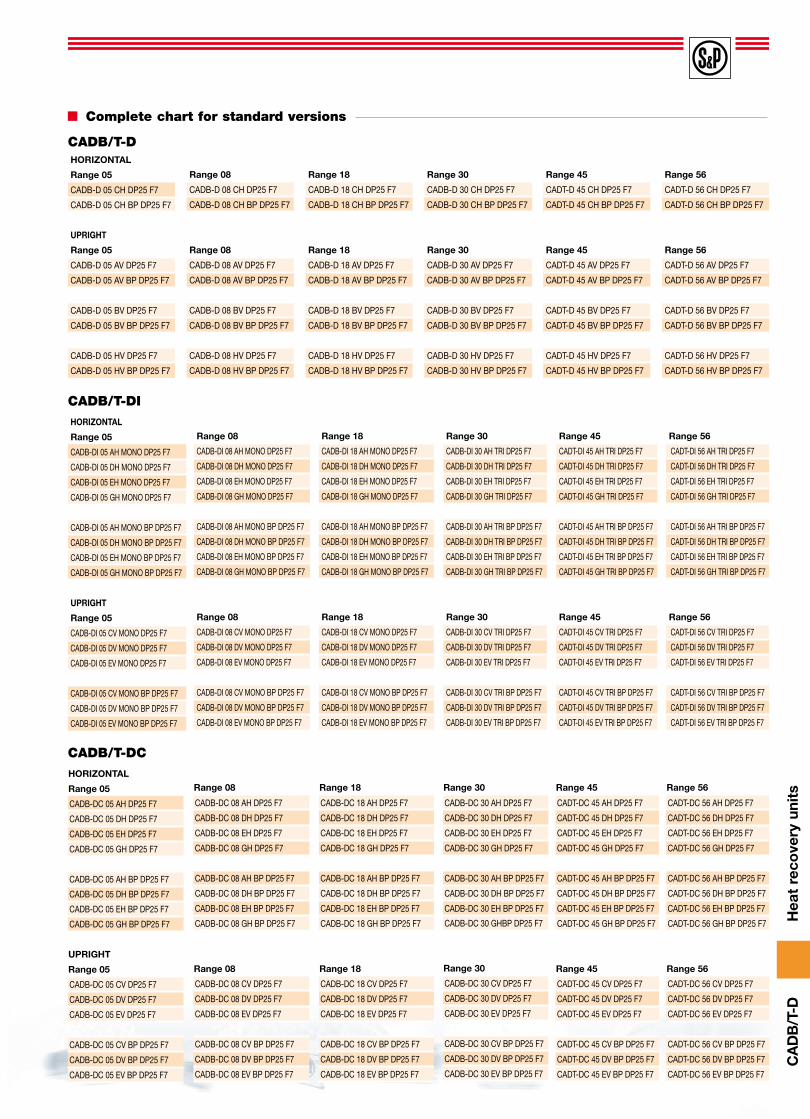
Complete chart for standard versions
CADB/t-DHORIZONTAL
Range 05
CADB-D 05 CH DP25 F7
CADB-D 05 CH BP DP25 F7
UPRIGHT
Range 05
CADB-D 05 AV DP25 F7
CADB-D 05 AV BP DP25 F7
CADB-D 05 BV DP25 F7
CADB-D 05 BV BP DP25 F7
CADB-D 05 HV DP25 F7
CADB-D 05 HV BP DP25 F7
Range 08
CADB-D 08 CH DP25 F7
CADB-D 08 CH BP DP25 F7
Range 08
CADB-D 08 AV DP25 F7
CADB-D 08 AV BP DP25 F7
CADB-D 08 BV DP25 F7
CADB-D 08 BV BP DP25 F7
CADB-D 08 HV DP25 F7
CADB-D 08 HV BP DP25 F7
Range 18
CADB-D 18 CH DP25 F7
CADB-D 18 CH BP DP25 F7
Range 18
CADB-D 18 AV DP25 F7
CADB-D 18 AV BP DP25 F7
CADB-D 18 BV DP25 F7
CADB-D 18 BV BP DP25 F7
CADB-D 18 HV DP25 F7
CADB-D 18 HV BP DP25 F7
Range 30
CADB-D 30 CH DP25 F7
CADB-D 30 CH BP DP25 F7
Range 30
CADB-D 30 AV DP25 F7
CADB-D 30 AV BP DP25 F7
CADB-D 30 BV DP25 F7
CADB-D 30 BV BP DP25 F7
CADB-D 30 HV DP25 F7
CADB-D 30 HV BP DP25 F7
Range 45
CADT-D 45 CH DP25 F7
CADT-D 45 CH BP DP25 F7
Range 45
CADT-D 45 AV DP25 F7
CADT-D 45 AV BP DP25 F7
CADT-D 45 BV DP25 F7
CADT-D 45 BV BP DP25 F7
CADT-D 45 HV DP25 F7
CADT-D 45 HV BP DP25 F7
Range 56
CADT-D 56 CH DP25 F7
CADT-D 56 CH BP DP25 F7
Range 56
CADT-D 56 AV DP25 F7
CADT-D 56 AV BP DP25 F7
CADT-D 56 BV DP25 F7
CADT-D 56 BV BP DP25 F7
CADT-D 56 HV DP25 F7
CADT-D 56 HV BP DP25 F7
HORIZONTAL
Range 05
CADB-DI 05 AH MONO DP25 F7
CADB-DI 05 DH MONO DP25 F7
CADB-DI 05 EH MONO DP25 F7
CADB-DI 05 GH MONO DP25 F7
CADB-DI 05 AH MONO BP DP25 F7
CADB-DI 05 DH MONO BP DP25 F7
CADB-DI 05 EH MONO BP DP25 F7
CADB-DI 05 GH MONO BP DP25 F7
UPRIGHT
Range 05
CADB-DI 05 CV MONO DP25 F7
CADB-DI 05 DV MONO DP25 F7
CADB-DI 05 EV MONO DP25 F7
CADB-DI 05 CV MONO BP DP25 F7
CADB-DI 05 DV MONO BP DP25 F7
CADB-DI 05 EV MONO BP DP25 F7
CADB/t-DI
Range 08
CADB-DI 08 AH MONO DP25 F7
CADB-DI 08 DH MONO DP25 F7
CADB-DI 08 EH MONO DP25 F7
CADB-DI 08 GH MONO DP25 F7
CADB-DI 08 AH MONO BP DP25 F7
CADB-DI 08 DH MONO BP DP25 F7
CADB-DI 08 EH MONO BP DP25 F7
CADB-DI 08 GH MONO BP DP25 F7
Range 08
CADB-DI 08 CV MONO DP25 F7
CADB-DI 08 DV MONO DP25 F7
CADB-DI 08 EV MONO DP25 F7
CADB-DI 08 CV MONO BP DP25 F7
CADB-DI 08 DV MONO BP DP25 F7
CADB-DI 08 EV MONO BP DP25 F7
Range 18
CADB-DI 18 AH MONO DP25 F7
CADB-DI 18 DH MONO DP25 F7
CADB-DI 18 EH MONO DP25 F7
CADB-DI 18 GH MONO DP25 F7
CADB-DI 18 AH MONO BP DP25 F7
CADB-DI 18 DH MONO BP DP25 F7
CADB-DI 18 EH MONO BP DP25 F7
CADB-DI 18 GH MONO BP DP25 F7
Range 18
CADB-DI 18 CV MONO DP25 F7
CADB-DI 18 DV MONO DP25 F7
CADB-DI 18 EV MONO DP25 F7
CADB-DI 18 CV MONO BP DP25 F7
CADB-DI 18 DV MONO BP DP25 F7
CADB-DI 18 EV MONO BP DP25 F7
Range 30
CADB-DI 30 AH TRI DP25 F7
CADB-DI 30 DH TRI DP25 F7
CADB-DI 30 EH TRI DP25 F7
CADB-DI 30 GH TRI DP25 F7
CADB-DI 30 AH TRI BP DP25 F7
CADB-DI 30 DH TRI BP DP25 F7
CADB-DI 30 EH TRI BP DP25 F7
CADB-DI 30 GH TRI BP DP25 F7
Range 30
CADB-DI 30 CV TRI DP25 F7
CADB-DI 30 DV TRI DP25 F7
CADB-DI 30 EV TRI DP25 F7
CADB-DI 30 CV TRI BP DP25 F7
CADB-DI 30 DV TRI BP DP25 F7
CADB-DI 30 EV TRI BP DP25 F7
Range 45
CADT-DI 45 AH TRI DP25 F7
CADT-DI 45 DH TRI DP25 F7
CADT-DI 45 EH TRI DP25 F7
CADT-DI 45 GH TRI DP25 F7
CADT-DI 45 AH TRI BP DP25 F7
CADT-DI 45 DH TRI BP DP25 F7
CADT-DI 45 EH TRI BP DP25 F7
CADT-DI 45 GH TRI BP DP25 F7
Range 45
CADT-DI 45 CV TRI DP25 F7
CADT-DI 45 DV TRI DP25 F7
CADT-DI 45 EV TRI DP25 F7
CADT-DI 45 CV TRI BP DP25 F7
CADT-DI 45 DV TRI BP DP25 F7
CADT-DI 45 EV TRI BP DP25 F7
Range 56
CADT-DI 56 AH TRI DP25 F7
CADT-DI 56 DH TRI DP25 F7
CADT-DI 56 EH TRI DP25 F7
CADT-DI 56 GH TRI DP25 F7
CADT-DI 56 AH TRI BP DP25 F7
CADT-DI 56 DH TRI BP DP25 F7
CADT-DI 56 EH TRI BP DP25 F7
CADT-DI 56 GH TRI BP DP25 F7
Range 56
CADT-DI 56 CV TRI DP25 F7
CADT-DI 56 DV TRI DP25 F7
CADT-DI 56 EV TRI DP25 F7
CADT-DI 56 CV TRI BP DP25 F7
CADT-DI 56 DV TRI BP DP25 F7
CADT-DI 56 EV TRI BP DP25 F7
HORIZONTAL
Range 05
CADB-DC 05 AH DP25 F7
CADB-DC 05 DH DP25 F7
CADB-DC 05 EH DP25 F7
CADB-DC 05 GH DP25 F7
CADB-DC 05 AH BP DP25 F7
CADB-DC 05 DH BP DP25 F7
CADB-DC 05 EH BP DP25 F7
CADB-DC 05 GH BP DP25 F7
UPRIGHT
Range 05
CADB-DC 05 CV DP25 F7
CADB-DC 05 DV DP25 F7
CADB-DC 05 EV DP25 F7
CADB-DC 05 CV BP DP25 F7
CADB-DC 05 DV BP DP25 F7
CADB-DC 05 EV BP DP25 F7
CADB/t-DC
Range 08
CADB-DC 08 AH DP25 F7
CADB-DC 08 DH DP25 F7
CADB-DC 08 EH DP25 F7
CADB-DC 08 GH DP25 F7
CADB-DC 08 AH BP DP25 F7
CADB-DC 08 DH BP DP25 F7
CADB-DC 08 EH BP DP25 F7
CADB-DC 08 GH BP DP25 F7
Range 08
CADB-DC 08 CV DP25 F7
CADB-DC 08 DV DP25 F7
CADB-DC 08 EV DP25 F7
CADB-DC 08 CV BP DP25 F7
CADB-DC 08 DV BP DP25 F7
CADB-DC 08 EV BP DP25 F7
Range 18
CADB-DC 18 AH DP25 F7
CADB-DC 18 DH DP25 F7
CADB-DC 18 EH DP25 F7
CADB-DC 18 GH DP25 F7
CADB-DC 18 AH BP DP25 F7
CADB-DC 18 DH BP DP25 F7
CADB-DC 18 EH BP DP25 F7
CADB-DC 18 GH BP DP25 F7
Range 18
CADB-DC 18 CV DP25 F7
CADB-DC 18 DV DP25 F7
CADB-DC 18 EV DP25 F7
CADB-DC 18 CV BP DP25 F7
CADB-DC 18 DV BP DP25 F7
CADB-DC 18 EV BP DP25 F7
Range 30
CADB-DC 30 AH DP25 F7
CADB-DC 30 DH DP25 F7
CADB-DC 30 EH DP25 F7
CADB-DC 30 GH DP25 F7
CADB-DC 30 AH BP DP25 F7
CADB-DC 30 DH BP DP25 F7
CADB-DC 30 EH BP DP25 F7
CADB-DC 30 GHBP DP25 F7
Range 30
CADB-DC 30 CV DP25 F7
CADB-DC 30 DV DP25 F7
CADB-DC 30 EV DP25 F7
CADB-DC 30 CV BP DP25 F7
CADB-DC 30 DV BP DP25 F7
CADB-DC 30 EV BP DP25 F7
Range 45
CADT-DC 45 AH DP25 F7
CADT-DC 45 DH DP25 F7
CADT-DC 45 EH DP25 F7
CADT-DC 45 GH DP25 F7
CADT-DC 45 AH BP DP25 F7
CADT-DC 45 DH BP DP25 F7
CADT-DC 45 EH BP DP25 F7
CADT-DC 45 GH BP DP25 F7
Range 45
CADT-DC 45 CV DP25 F7
CADT-DC 45 DV DP25 F7
CADT-DC 45 EV DP25 F7
CADT-DC 45 CV BP DP25 F7
CADT-DC 45 DV BP DP25 F7
CADT-DC 45 EV BP DP25 F7
Range 56
CADT-DC 56 AH DP25 F7
CADT-DC 56 DH DP25 F7
CADT-DC 56 EH DP25 F7
CADT-DC 56 GH DP25 F7
CADT-DC 56 AH BP DP25 F7
CADT-DC 56 DH BP DP25 F7
CADT-DC 56 EH BP DP25 F7
CADT-DC 56 GH BP DP25 F7
Range 56
CADT-DC 56 CV DP25 F7
CADT-DC 56 DV DP25 F7
CADT-DC 56 EV DP25 F7
CADT-DC 56 CV BP DP25 F7
CADT-DC 56 DV BP DP25 F7
CADT-DC 56 EV BP DP25 F7

Hea
t re
cove
ry u
nits
CA
DB
/T-D
Base on these standard configurations other configurations can be quickly and simply adapted by the installer.
CADB/t-D/DI/DC DP25 F7 standard configurations
CADB/t-D
CADB-D 05/08/18/30 CHCADT-D 45/56 CH
CADB-D 05/08/18/30 AVCADT-D 45/56 AV
CADB-D 05/08/18/30 BVCADT-D 45/56 BV
CADB-D 05/08/18/30 HVCADT-D 45/56 HV
Conf. CH Conf. AV Conf. BV Conf. HV
HORIZONTAL UPRIGHT
CADB/T-DI
CADB-DI 05/08/18 AH MONOCADB-DI 30 AH TRICADT-DI 45/56 AH TRI
CADB-DI 05/08/18 DH MONOCADB-DI 30 DH TRICADT-DI 45/56 DH TRI
CADB-DI 05/08/18 EH MONOCADB-DI 30 EH TRICADT-DI 45/56 EH TRI
CADB-DI 05/08/18 GH MONOCADB-DI 30 GH TRICADT-DI 45/56 GH TRI
CADB-DI 05/08/18 CV MONOCADB-DI 30 CV TRICADT-DI 45/56 CV TRI
CADB-DI 05/08/18 DV MONOCADB-DI 30 DV TRICADT-DI 45/56 DV TRI
CADB-DI 05/08/18 EV MONOCADB-DI 30 EV TRICADT-DI 45/56 EV TRI
CONf. AH CONf. DH CONf. EH CONf. GH
CONf. CV CONf. DV CONf. EV
HORIZONTAL
UPRIGHT
FILTRO
DESAGÜE
VENTILADORCENTRÍFUGO
AIRE NUEVO
AIRE EXTRAIDO
BATERÍAELÉCTRICA
BATERÍADE AGUA
NEW AIR
EXTRACTED AIR

Hea
t re
cove
ry u
nits
CA
DB
/T-D
CADB/t-D/DI/DC DP25 F7 standard configurations
CADB/t-DC
CADB-DC 05/08/18/30 AHCADT-DC 45/56 AH
CADB-DC 05/08/18/30 DHCADT-DC 45/56 DH
CADB-DC 05/08/18/30 EHCADT-DC 45/56 EH
CADB-DC 05/08/18/30 GHCADT-DC 45/56 GH
CADB-DC 05/08/18/30 CVCADT-DC 45/56 CV
CADB-DC 05/08/18/30 DVCADT-DC 45/56 DV
CADB-DC 05/08/18/30 EVCADT-DC 45/56 EV
Conf. AH Conf. DH Conf. EH Conf. GH
Conf. CV Conf. DV Conf. EV
HORIZONTAL
UPRIGHT
FILTRO
DESAGÜE
VENTILADORCENTRÍFUGO
AIRE NUEVO
AIRE EXTRAIDO
BATERÍAELÉCTRICA
BATERÍADE AGUA
NEW AIR
EXTRACTED AIR

Hea
t re
cove
ry u
nits
CA
DB
/T-D
CADB/t-D DP25 F7. Dimensions (mm)
A
E
a
b
ø1/2"
ø
D
h
C
B
A
E
a
b
ø1/2"
ø
D
h
C
B
Horizontal configuration (H)
Model A B C Ø D E a b h Weight(Kg)
CADB-D 05 640 640 345 200 172,5 175 120 265 200 32
CADB-D 08 820 820 360 250 180 220 120 265 200 44
CADB-D 18 1040 1040 535 315 315 275 120 265 200 91
CADB-D 30 1270 1270 630 355 360 332,5 120 265 200 125
CADT-D 45 1300 1200 855 450 427,5 315 200 400 650 171
CADT-D 56 1300 1200 855 450 427,5 315 200 400 650 176
Horizontal configuration (H) con by-pass (BP)
Model A B C Ø D E a b h Weight(Kg)
CADB-D 05 640 640 450 200 172,5 175 120 265 200 41
CADB-D 08 820 820 465 250 180 220 120 265 200 56
CADB-D 18 1040 1040 640 315 315 275 120 265 200 107
CADB-D 30 1270 1270 735 355 360 332,5 120 265 200 146
CADT-D 45 1300 1200 855 450 427,5 315 200 400 650 171
CADT-D 56 1300 1200 855 450 427,5 315 200 400 650 176
Electrical panel dimensions for all versions CADB-D/DC/DI Regulation with an electronic microprocessor (BASIC, PROGRAM, ADVANZ or DOMO).
* The electrical panel is installed in the side panel fan drive.
* The electrical panel is installed in the side panel fan drive.

Hea
t re
cove
ry u
nits
CA
DB
/T-D
CADB/t-D DP25 F7. Dimensions (mm)
C
D
ø1/2"
F
E
a
h
A
b
ø
B
100
C
D
ø1/2"
F
E
a
h
A
b
ø
B
100
A
b
C
D
ø
B
100
ø1/2"
F
E
a
h
A
b
C
D
ø
B
100
ø1/2"
F
E
a
h
Upright configuration (V)
Model A B C Ø D E F a b h Weight(Kg)
CADB-D 05 640 640 345 200 172,5 175 175 120 265 200 33
CADB-D 08 820 820 360 250 180 220 220 120 265 200 45
CADB-D 18 1040 1040 535 315 315 225 325 120 265 200 92
CADB-D 30 1270 1270 630 355 360 240 425 120 265 200 126
CADT-D 45 1300 1200 855 450 427,5 305 305 200 400 650 172
CADT-D 56 1300 1200 855 450 427,5 305 305 200 400 650 177
Upright configuration (V) con by-pass (BP)
Model A B C Ø D E F a b h Weight(Kg)
CADB-D 05 640 640 450 200 172,5 175 175 120 265 200 42
CADB-D 08 820 820 465 250 180 220 220 120 265 200 57
CADB-D 18 1040 1040 640 315 315 225 325 120 265 200 108
CADB-D 30 1270 1270 735 355 360 240 425 120 265 200 147
CADT-D 45 1300 1200 855 450 427,5 315 305 200 400 650 172
CADT-D 56 1300 1200 855 450 427,5 315 305 200 400 650 177
Electrical panel dimensions for all versions CADB-D/DC/DI Regulation with an electronic microprocessor (BASIC, PROGRAM, ADVANZ or DOMO).
* The electrical panel is installed in the side panel fan drive, can be positioned up, down, right or left (depending on configuration of the heat recovery).
* The electrical panel is installed in the side panel fan drive, can be positioned up, down, right or left (depending on configuration of the heat recovery).

Hea
t re
cove
ry u
nits
CA
DB
/T-D
CADB/t-DI-DC DP25 F7. Dimensions (mm)
A
b
ø1/2"
ø
øR
D
E
C
a
h
B
A
b
ø1/2"
øR
ø
D
E
C
a
h
B
Horizontal configuration (H)
Model A B C Ø D E ØR a b h Weight(Kg)
CADB-DI-DC 05 960 640 345 200 172,5 175 1/2" 120 265 200 40
CADB-DI-DC 08 1230 820 360 250 180 220 1/2" 120 265 200 56
CADB-DI-DC 18 1560 1040 535 315 315 275 1/2" 120 265 200 110
CADB-DI-DC 30 1905 1270 630 355 360 332,5 1" 120 265 200 155
CADT-DI-DC 45 1550 1200 855 450 427,5 315 1" 200 400 650 195
CADT-DI-DC 56 1550 1200 855 450 427,5 315 1" 200 400 650 200
Horizontal configuration (H) con by-pass (BP)
Model A B C Ø D E ØR a b h Weight(Kg)
CADB-DI-DC 05 960 640 450 200 172,5 175 1/2" 120 265 200 49
CADB-DI-DC 08 1230 820 465 250 180 220 1/2" 120 265 200 68
CADB-DI-DC 18 1560 1040 640 315 315 275 1/2" 120 265 200 126
CADB-DI-DC 30 1905 1270 735 355 360 332,5 1" 120 265 200 176
CADT-DI-DC 45 1550 1200 855 450 427,5 315 1" 200 400 650 195
CADT-DI-DC 56 1550 1200 855 450 427,5 315 1" 200 400 650 200
Electrical panel dimensions for all versions CADB-D/DC/DI Regulation with an electronic microprocessor (BASIC, PROGRAM, ADVANZ or DOMO).
* The electrical panel is installed in the side panel fan drive.
* The electrical panel is installed in the side panel fan drive.

Hea
t re
cove
ry u
nits
CA
DB
/T-D
CADB/t-DI-DC DP25 F7. Dimensions (mm)
A
b
ø
B
100
øR
C
D
ø1/2"
F
E
a
h
A
b
ø
B
100
øR
C
D
ø1/2"
F
E
a
h
Upright configuration (V)
Model A B C Ø D E F ØR a b h Weight(Kg)
CADB-DI-DC 05 960 640 345 200 172,5 175 175 1/2" 120 265 200 41
CADB-DI-DC 08 1230 820 360 250 180 220 220 1/2" 120 265 200 57
CADB-DI-DC 18 1560 1040 535 315 315 225 325 1/2" 120 265 200 111
CADB-DI-DC 30 1905 1270 630 355 360 240 425 1" 120 265 200 156
CADT-DI-DC 45 1550 1200 855 450 427,5 305 305 1" 200 400 650 196
CADT-DI-DC 56 1550 1200 855 450 427,5 305 305 1" 200 400 650 201
Upright configuration (V) con by-pass (BP)
Model A B C Ø D E F ØR a b h Weight(Kg)
CADB-DI-DC 05 960 640 450 200 172,5 175 175 1/2" 120 265 200 50
CADB-DI-DC 08 1230 820 465 250 180 220 220 1/2" 120 265 200 69
CADB-DI-DC 18 1560 1040 640 315 315 275 325 1/2" 120 265 200 127
CADB-DI-DC 30 1905 1270 735 355 360 332,5 425 1" 120 265 200 177
CADT-DI-DC 45 1550 1200 855 450 427,5 305 305 1" 200 400 650 196
CADT-DI-DC 56 1550 1200 855 450 427,5 305 305 1" 200 400 650 201
Electrical panel dimensions for all versions CADB-D/DC/DI Regulation with an electronic microprocessor (BASIC, PROGRAM, ADVANZ or DOMO).
* The electrical panel is installed in the side panel fan drive, can be positioned up, down, right or left (depending on configuration of the heat recovery).
* The electrical panel is installed in the side panel fan drive, can be positioned up, down, right or left (depending on configuration of the heat recovery).

Hea
t re
cove
ry u
nits
CA
DB
/T-D
0 100 200 300 400 500 600 Qv (m3/h)
0
50
100
150
200
250
300
350
400
PePa mmca
0
5
10
15
20
25
30
35
40
0
100
200
300
400
500
600
700
800Pabs ( W )
5052545658 Rend ( % )
V1
V2
V3
V1
V4
CADB-D/DI/DC 05
Performance curves
– Qv = Volume in m3/h.– Ps = Static pressure in mmwg and Pa– Pabs = Power absorbed at the maximum velocity (W).– Normal dry air at 20°C and 760 mmHg– Performance data in accordance with ISO 5801 and AMCA 210-99
Standards.
Additional pressure dropResistances: All 10 Pa models.Batteries: 05 Range 16Pa, 08 Range 13Pa, 18 Range 31Pa,
30 Range 27Pa, 45 Range 60Pa, 56 Range 100Pa.
CADB-D/DI/DC 18 CADB-D/DI/DC 30
CADT-D/DI/DC 45
Ps
Eff. (%)
mmWG
0 200 400 600 800 1000 1200 Qv (m3/h)
0
50
100
150
200
250
300
350
400
450
500
PePa mmca
0
5
10
15
20
25
30
35
40
45
50
300
400
500
600
700
800Pabs ( W )
535455565758596061 Rend ( % )
V1
V2
V3
V1
V4
CADB-D/DI/DC 08PsmmWG
0 1000 2000 3000 4000 5000 6000 7000 Qv (m3/h)
0
100
200
300
400
500
600
700
800
PePa mmca
0
10
20
30
40
50
60
70
80
0
1000
2000
3000
4000
5000
6000
7000
8000Pabs ( W )
63 60 59 58 56 54 53 52 Rend ( % )
CADB-D/DI/DC 56PsPs
PsPs
mmWGmmWG
mmWGmmWG
Eff. (%)
Eff. (%)
Eff. (%) Eff. (%)
Eff. (%)

Hea
t re
cove
ry u
nits
CA
DB
/T-D
Acoustical characteristics
Mounting accessories
Lw, levels of noise transmitted in the inlet conduit and radiated in accordance with regulation EN ISO 3747.
AFRSpare filter
ModelSpare filter
Spare filter G4 Spare filter F7 Spare filter F9
CADB-D/DI/DC 05 AFR-D/DI/DC 05 G4 AFR-D/DI/DC 05 F7 AFR-D/DI/DC 05 F9
CADB-D/DI/DC 08 AFR-D/DI/DC 08 G4 AFR-D/DI/DC 08 F7 AFR-D/DI/DC 08 F9
CADB-D/DI/DC 18 AFR-D/DI/DC 18 G4 AFR-D/DI/DC 18 F7 AFR-D/DI/DC 18 F9
CADB-D/DI/DC 30 AFR-D/DI/DC 30 G4 AFR-D/DI/DC 30 F7 AFR-D/DI/DC 30 F9
CADT-D/DI/DC 45 AFR-D/DI/DC 45/56 G4 AFR-D/DI/DC 45/56 F7 AFR-D/DI/DC 45/56 F9
CADT-D/DI/DC 56 AFR-D/DI/DC 45/56 G4 AFR-D/DI/DC 45/56 F7 AFR-D/DI/DC 45/56 F9
Noise transmitted
CADB-D 05 125 250 500 1000 2000 4000 8000 dB(A)
LW V1 21,5 17,5 15 27 16 7 4 29
LW V2 28,5 23,5 21 36 25 14 7 37
LW V3 33,5 29,5 27 42 33 23 15 43
LW V4 38,5 35,5 32 46 40 31 24 48
Noise radiated
CADB-D 05 125 250 500 1000 2000 4000 8000 dB(A)
LW V1 15,5 13,5 12 23 13 6 4 25
LW V2 21,5 18,5 17 31 22 12 5 32
LW V3 26,5 23,5 22 36 28 20 12 37
LW V4 30,5 28,5 27 39 34 27 20 41
Noise transmitted
CADB-D 08 125 250 500 1000 2000 4000 8000 dB(A)
LW V1 30,5 25,5 23 41 26 24 17 42
LW V2 36,5 33,5 31 47 36 34 29 48
LW V3 40,5 38,5 36 51 43 41 38 53
LW V4 43,5 41,5 40 53 47 45 41 55
Noise radiated
CADB-D 08 125 250 500 1000 2000 4000 8000 dB(A)
LW V1 23,5 20,5 19 35 23 20 14 36
LW V2 28,5 27,5 26 40 31 29 25 41
LW V3 32,5 31,5 30 43 37 35 32 45
LW V4 34,5 33,5 33 45 40 38 35 48
Noise transmitted
CADB-D 18 125 250 500 1000 2000 4000 8000 dB(A)
LW V1 49,5 48,5 57 62 59 53 43 65
LW V2 52,5 51,5 59 64 61 56 47 67
LW V3 51,5 53,5 61 65 63 59 20 69
Noise radiated
CADB-D 18 125 250 500 1000 2000 4000 8000 dB(A)
LW V1 39,5 39,5 48 53 50 45 36 56
LW V2 42,5 42,5 50 54 52 48 40 58
LW V3 41,5 44,5 51 55 54 50 42 59
Noise transmitted
CADB-D 30 125 250 500 1000 2000 4000 8000 dB(A)
LW V1 40,5 41,5 47 48 42 32 27 52
LW V2 53,5 50,5 60 64 62 58 47 68
LW V3 55,5 62,5 69 75 74 71 63 79
Noise radiated
CADB-D 30 125 250 500 1000 2000 4000 8000 dB(A)
LW V1 32,5 33,5 40 40 36 28 22 45
LW V2 42,5 41,5 51 54 53 49 40 58
LW V3 44,5 51,5 58 64 63 61 54 68
Noise transmitted
CADT-D 45 125 250 500 1000 2000 4000 8000 dB(A)
LW Vmax 66,5 67,5 67 69 64 65 54 75
Noise radiated
CADT-D 45 125 250 500 1000 2000 4000 8000 dB(A)
LW Vmax 62,5 61,5 61 63 58 57 41 69
Noise transmitted
CADT-D 56 125 250 500 1000 2000 4000 8000 dB(A)
LW Vmax 68,5 69,5 70 70 66 69 56 77
Noise radiated
CADT-D 56 125 250 500 1000 2000 4000 8000 dB(A)
LW Vmax 64,5 62,5 62 63 58 59 42 70

Hea
t re
cove
ry u
nits
CA
DB
/T-D
Mounting accessories
MSOFlexible coupling
Model Flexible coupling
CADB-D/DI/DC 05 MSO-200
CADB-D/DI/DC 08 MSO-250
CADB-D/DI/DC 18 MSO-315
CADB-D/DI/DC 30 MSO-355
CADB-D/DI/DC 45 MSO-450
CADB-D/DI/DC 56 MSO-450
CAFIL*Filtering box
Model Filtering box
CADB-D/DI/DC 05 CAFIL-200
CADB-D/DI/DC 08 CAFIL-250
CADB-D/DI/DC 18 CAFIL-315
CADB-D/DI/DC 30 CAFIL-355
CADB-D/DI/DC 45 CAFIL-450
CADB-D/DI/DC 56 CAFIL-450
APCInlet/discharge protection guards
Model Inlet/discharge protection guards
CADB-D/DI/DC 05 APC-200
CADB-D/DI/DC 08 APC-250
CADB-D/DI/DC 18 APC-315
CADB-D/DI/DC 30 APC-355
CADB-D/DI/DC 45 APC-450
CADB-D/DI/DC 56 APC-450
SILSound attenuators to mount at theinlet and/or discharge of the heatrecovery units
Model Sound attenuator
CADB-D/DI/DC 05 SIL-200
CADB-D/DI/DC 08 SIL-250
CADB-D/DI/DC 18 SIL-315
CADB-D/DI/DC 30 SIL-355
CADB-D/DI/DC 45 SIL-450
CADB-D/DI/DC 56 SIL-450
TPP D-H
TPP D-V
TPP DI/DC-H
TPP DI/DC-V
Model Rain Cap
CADB-D 05 H TPP D-H 05
CADB-D 08 H TPP D-H 08
CADB-D 18 H TPP D-H 18
CADB-D 30 H TPP D-H 30
CADT-D 45 H TPP D-H 45/56
CADT-D 56 H TPP D-H 45/56
Model Rain Cap
CADB-D 05 V TPP D-V 05
CADB-D 08 V TPP D-V 08
CADB-D 18 V TPP D-V 18
CADB-D 30 V TPP D-V 30
CADT-D 45 V TPP D-V 45/56
CADT-D 56 V TPP D-V 45/56
Model Rain Cap
CADB-DI/DC 05 H TPP DI/DC-H 05
CADB-DI/DC 08 H TPP DI/DC-H 08
CADB-DI/DC 18 H TPP DI/DC-H 18
CADB-DI/DC 30 H TPP DI/DC-H 30
CADT-DI/DC 45 H TPP DI/DC-H 45/56
CADT-DI/DC 56 H TPP DI/DC-H 45/56
Model Rain Cap
CADB-DI/DC 05 V TPP DI/DC-V 05
CADB-DI/DC 08 V TPP DI/DC-V 08
CADB-DI/DC 18 V TPP DI/DC-V 18
CADB-DI/DC 30 V TPP DI/DC-V 30
CADT-DI/DC 45 V TPP DI/DC-V 45/56
CADT-DI/DC 56 V TPP DI/DC-V 45/56
TTP D/DI/DC BPTo heat recovery horizontal with by-pass
Model Rain Cap
CADB-D 05 H BP TPP D-H 05 BP
CADB-D 08 H BP TPP D-H 08 BP
CADB-D 18 H BP TPP D-H 18 BP
CADB-D 30 H BP TPP-D-H 30 BP
CADB-DI/DC 05 H BP TPP-DI/DC-H 05 BP
CADB-DI/DC 08 H BP TPP-DI/DC-H 08 BP
CADB-DI/DC 18 H BP TPP-DI/DC-H 18 BP
CADB-DI/DC 30 H BP TPP-DI/DC-H 30 BP
TPPExternal rain protection canopy
SIFÓN RECUPERADORES*Drain water drainage of the heat recovery
See complete information on the HEAT RECOVERY ACCESSORIES.

Hea
t re
cove
ry u
nits
CA
DB
/T-D
5º
Versions CADB-D 05 H to 30 Hwith by-pass
Model A B
CADB-D 05 V 610 900
CADB-D 08 V 640 1110
CADB-D 18 V 900 1400
CADB-D 30 V 1100 1750
CADT-D 45 V 1230 1710
CADT-D 56 V 1230 1710
AB
5º
Versions CADB/T-D V with and without by-pass
5º
5º
Versions CADB-DI/DC 05 H to 30 Hwith by-pass
Versions CADB-DI/DC 05 H to 30 Hwithout by-pass
Versions CADT-DI/DC 45 H and 56H with and without by-pass
Model A B
CADB-DI/DC 05 V 610 1220
CADB-DI/DC 08 V 640 1530
CADB-DI/DC 18 V 900 1920
CADB-DI/DC 30 V 1100 2395
CADT-DI/DC 45 V 1230 1960
CADT-DI/DC 56 V 1230 1960
A
B
5º
Versions CADB/T-DI/DC Vwith and without by-pass
AB
Model A B
CADB-D 05 H 770 770
CADB-D 08 H 980 980
CADB-D 18 H 1270 1270
CADB-D 30 H 1570 1570
CADT-D 45 H 1630 1730
CADT-D 56 H 1630 1730
5º
Versions CADB-D 05 H to 30 Hwithout by-pass
Versions CADT-D 45 H and56 H with and without by-pass
External rain protection canopyincorporates 4 side panels
AB
Model A B
CADB-DI/DC 05 H 770 1090
CADB-DI/DC 08 H 980 1400
CADB-DI/DC 18 H 1270 1790
CADB-DI/DC 30 H 1570 2215
CADT-DI/DC 45 H 1630 1980
CADT-DI/DC 56 H 1630 1980
External rain protection canopyincorporates 4 side panels
Mounting accessories

Hea
t re
cove
ry u
nits
CA
DB
/T-D
Electrical accessories
RQA3Automatic speed adjustment according toCO2 concentration.Works together with a CO2 probe(SCO2-A 1/10V ambient and, SCO2-AD orin the SCO2-G conduit).Only for 05 and 08 models.
Model Variable frequency drive Sensor
CADB-D/DI/DC 05 RQA3 SCO2-A / SCO2-AD / SCO2-G
CADB-D/DI/DC 08 RQA3 SCO2-A / SCO2-AD / SCO2-G
CADB-D/DI/DC 18 VAPZ-11 SCO2-A / SCO2-AD / SCO2-G
CADB-D/DI/DC 30 VAPZ-11 SCO2-A / SCO2-AD / SCO2-G
CADB-D/DI/DC 45 VFTM TRI 2,2 SCO2-A / SCO2-AD / SCO2-G
CADB-D/DI/DC 56 VFTM TRI 4 SCO2-A / SCO2-AD / SCO2-G
Accessories for the Variable Air Volume System by CO2 Accessories for Constant Pressure operation
VFTM TRIVariable frequency drive enabling the fanspeed to be modified according to CO2 con-centration.Works together with a CO2 probe (SCO2-Aambient and SCO2-AD or in the SCO2-Gconduit).Only for 45 and 56 models.
Model Variable frequency drive Sensor
CADB-D/DI/DC 05 Pack PR 5A 0-300Pa Included
CADB-D/DI/DC 08 Pack PR 5A 0-300Pa Included
CADB-D/DI/DC 18 Pack PR 11A 0-800Pa Included
CADB-D/DI/DC 30 Pack PR 11A 0-800Pa Included
CADB-D/DI/DC 45 VFTM TRI 2,2 TDP-S / TDP-D
CADB-D/DI/DC 56 VFTM TRI 4 TDP-S / TDP-D
VAPZ-11Controller, enabling the fan speed to bemodified according to CO2 concentration.Maximum current 11A.Works together with a CO2 probe (SCO2-Aambient and, SCO2-A and SCO2-AD or inthe SCO2-G conduit).Only for 18 and 30 models.
Model Electricalsupply
Maximum current
(A)
Voltage
(V)
IP Operatingtemperature
range
Dimensions LxAxH (mm)
VAPZ-11 230V-50Hz 11 110-230 IP55 -10 to +50 205x115x92
Pack PRVoltage regulator for single-phase motors with pressure probe included for control of constant pressure systems.
Model Electricalsupply
Maximumcurrent
(A)
Voltage
(V)
IP Operatingtemp. range
DimensionsLxAxH(mm)
Pack PR 5A 230V-50/60Hz 5 110-230 IP55 -10 to +50 176x200x80
Pack PR 11A 230V-50/60Hz 11 110-230 IP55 -10 to +50 176x200x80
SCO2-G 0/10 VCO2 sensor probe for duct mounting.Enable control of the ventilation in ductworkaccording to the CO2 concentration of the aircirculating through it.
For controlled equipment only a 0-10 V probe can be connected.
Model Electricalsupply
Power
(W)
Voltage
(V)
IP CO2range(pm)
Dimensions LxAxH (mm)
SCO2-G 0/10 V
24VDC-24VAC 5 0-10 Box IP65 0-2000 80x238x80
TDP-S / TDP-DPressure sensor.Enables you to control the pressure in thefan inlet.
TDP-SStandard pressure sensor.TDP-DPressure sensor, with display.
Model Electricalsupply
Maximumpower
(VA)
ØConnectors
(mm)
Voltage IP Pressurerange(Pa)
DimensionsLxAxH(mm)
TDP-S24VAC-24VDC 4 6,2
0-10 V / 4-20 mA
IP54 0-2500 75x36x80TDP-D
SCO2-A 0/10 VAmbient CO2 and temperature sensor.Enables control of the ventilation in sectionsof conduit according to the temperatureand relative humidity of the air circulatingthrough it or to the temperature.
SCO2-ADAmbient CO2 and temperature sensorwith display.Enable control of the ventilation ductworkaccording to the temperature and relativehumidity of the air circulating through it or tothe temperature.
Model Electricalsupply
Power
(W)
Voltage Heightinstal.
(m)
IP CO2range(pm)
Temperaturerange(ºC)
Dimensions LxAxH (mm)
SCO2-A 0/10 V 24VDC-
24VAC 5
0-10V1,5-3,5 IP20 0-2000 0-50 85x26x100
SCO2-AD 4-20mA

Hea
t re
cove
ry u
nits
CA
DB
/T-D
COM3 / COM43 and 4 speed switch
Model Switch Maximum current (A)
CADB-D/DI/DC 05 COM4 12
CADB-D/DI/DC 08 COM4 12
CADB-D/DI/DC 18 COM3 20
CADB-D/DI/DC 30 COM3 20
Electrical accessories
SQAAutomatically switches the fan on when the quality of the ambient air deteriorates below an acceptable level due to fumes, odours, tobacco, smoke or dampness etc…Adjustable run-on-timer facility which enables the fan to operate for a pre-selected time period after the air quality sensor has switched off.Important: this sensor must not be used to detect combustible gases or fires ans in con-nection with any safety alarm systems.
IP protection
Class Maximumcurrent
(A)
Operatingtemperature
(ºC)
Timeradjustment
IP21 II ( ) 2* 0-50 1-25 min.
* For inductive loads.
PULSER Electronic controller to regulate the heat output for single phase electric heater battery up to 16A, in order to maintain a constant pre-select-ed temperature.Depending on the selected temperature, the controller pulses the entire power output anduses a time-proportional control to main-tain that temperature. The PULSER incorpo-rates a built-in room temperature sensor with an input for external sensor. IP-30. Maximum heaterpower 3,6kW.
PULSER-ADDSupplementary unit for slave control fromanother PULSER to control batteries withpower ratings superior to the PULSERcapacity (3600W -16A- 230V).
TTC-25Electronic controller to regulate the heat output for three phase electric heater battery up to 25A, in order to maintain a constant pre-selected temperature.Depending on the selected temperature, thecontroller pulses the entire power output and uses a time-proportional control to maintain that temperature. The TTC-25 is designed to be fitted in a cabinet on DIN-rail. IP-20.
TG-R430Room sensor with set point adjustmentbetween 0 and +30ºC.
PULSER MElectronic controller similar to the PULSER, incorporating in addition, input for an external duct sensor to control minimum or maximum temperature limitations. IP-30. Maximum hea-terpower 3,6kW.
PULSER DElectronic controller to regulate the heat out-put for single phase electric heater battery up to 16A, in order to maintain a constant pre-selected temperature.Depending on the selected temperature, the controller pulses the entire power output and uses a time-proportional control to maintain that temperature. The PULSER D is designed to be fitted in a cabinet on DIN-rail. IP-20. Maximum heater power 3,6kW.).
TBI-10Potentiometer mounted on the main board panel for setting temperature between -20 and +10ºC. Used with the PULSER-D or TTC-25 mounted within cabinet, to set the minimum air temperature before entering in the heat exchanger.

Hea
t re
cove
ry u
nits
CA
DB
/T-D
Electrical accessories
MCR-1Timer with set point between 1 sec and 100 h.Used in an electric heating system to delay the fan switch off after disconnecting the system.
TBI-30Potentiometer mounted on the main board panel for setting temperature between 0 and +30ºC. Used with the Pulser-D and with a TTC-25 duct sensor to set the air temperatu-re after the electric battery in post heatingoperation.
TRANSFORMER CADB/T-DCTransformer 200V / 24V AC for vales supply.
PRESSURE SWITCH DPS 2-30Differential pressure switch to control the fan running and the filter clogging up. Workingpressure range from 2 to 30 mmWG.
TG-K310, TG-K330 and TG-K360Duct temperature sensor.Temperature range:TG-K310 from -20 to 10ºCTG-K330 from 0 to 30ºCTG-K360 from 0 to 60ºC
3WV CADB/T-DC*Motorized 3-way valves.
* See complete information on the HEAT RECOVERY ACCESSORIES.
Model Valve DN (mm)
DN (")
Kvs (m3/h)
CADB-D/DI/DC 05 3 WV CADB-DC 05/30 15 1/2 2,5
CADB-D/DI/DC 08 3 WV CADB-DC 08/18 15 1/2 1,6
CADB-D/DI/DC 18 3 WV CADB-DC 08/18 15 1/2 1,6
CADB-D/DI/DC 30 3 WV CADB-DC 05/30 15 1/2 2,5
CADT-D/DI/DC 45 3 WV CADT-DC 45/56 20 3/4 6,3
CADT-D/DI/DC 56 3 WV CADT-DC 45/56 20 3/4 6,3

Hea
t re
cove
ry u
nits
CA
DB
/T-D
Ambient temperature and inlet air temperature control
Heat recovery CADB/T-D DP25 F7Electric heating batteries with built-in temperature control to fit on versions CADB/T-D: consists of electric resistances, conduit probe, electric battery regulator and internal potentiometer.
Heat recovery CADB/T-DI DP25 F7Control elements needed for managing the operation of the built-in resistances in the heat exchangers.
* The ADD Pulser should be installed with the M Pulser when the power exceeds 3.6 kW.
Model Heat recovery Ø(mm)
Power(W)
Voltage Nº stages Minimum airflow (m3/h)
ABE-SCT 200M CADB-D 05 200 2.000 230V-1-50Hz 1 170
ABE-SCT 250M CADB-D 08 250 4.000 230V-1-50Hz 2 270
ABE-SCT 315M CADB-D 18 315 6.000 230V-1-50Hz 2 430
ABE-SCT 355T CADB-D 30 355 8.000 400V-3-50Hz 2 560
ABE-SCT 450T CADT-D 45 450 12.000 400V-3-50Hz 2 710
ABE-SCT 500T CADT-D 56 450 12.000 400V-3-50Hz 2 1870
Built-in electric heaterAir ambient temperature control
Supply airtemperature
controlOptional
Controller in room Controller within cabinet (Din-rail) Duct sensorto limit
supply airtemperature
0/60ºC
Externalpotentiometer
on cabinet0/30ºC
TimerModel Supply
Power(kW)
Nº of stage
Electriccontroller
Controllerwith Min/Max
limitingsensor
Adjust.room
sensor0/30ºC
Electriccontroller
Duct sensor 0/30ºC
CADB-DI 05 Single phase 230V 2 1 PULSER PULSER M TG-R430 PULSER D TG-K330 TG-K360 TBI-30 MCR-1
CADB-DI 08 Single phase 230V 4 2 PULSER + P.ADD* PULSER + P.ADD* TG-R430 PULSER D + P.ADD* TG-K330 TG-K360 TBI-30 MCR-1
CADB-DI 18 Single phase 230V 6 2 PULSER + P.ADD* PULSER + P.ADD* TG-R430 PULSER D + P.ADD* TG-K330 TG-K360 TBI-30 MCR-1
CADB-DI 30 Three phase 400V 8 2 - - TG-R430 TTC-25 TG-K330 TG-K360 TBI-30 MCR-1
CADT-DI 45 Three phase 400V 12 2 - - TG-R430 TTC-25 TG-K330 TG-K360 TBI-30 MCR-1
CADT-DI 56 Three phase 400V 12 2 - - TG-R430 TTC-25 TG-K330 TG-K360 TBI-30 MCR-1
Installation with externalelectric heater Electric
heater type
Defrosting operation control(Heat exchanger protection)
Supply air temperature control
Model SupplyØ
(mm)Power(kW)
Electric heaterDuct
sensor -20/10ºC
Externalpotentiometer
-20/30ºCElectric heater
Duct sensor 0/30ºC
Externalpotentiometer
0/30ºC
CADB-D 05 Single phase 230V 200 2,1 ABE-200/2M PULSER D TG-K310 TBI-10 PULSER D TG-K330 TBI-30
CADB-D 08 Single phase 230V 250 3 ABE-250/3M PULSER D TG-K310 TBI-10 PULSER D TG-K330 TBI-30
CADB-D 18 Single phase 230V 315 4 ABE-315/4M PULSER D + P.ADD TG-K310 TBI-10 PULSER D + P.ADD TG-K330 TBI-30
CADB-D 30 Three phase 400V 400 6 ABE-355/60T TTC-25 TG-K310 TBI-10 TTC 25 TG-K330 TBI-30
CADT-D 45 Three phase 400V 400 9 ABE-400/90T TTC-25 TG-K310 TBI-10 TTC 25 TG-K330 TBI-30
CADT-D 56 Three phase 400V 400 9 ABE-400/90T TTC-25 TG-K310 TBI-10 TTC 25 TG-K330 TBI-30

Hea
t re
cove
ry u
nits
CA
DB
/T-D
The heater battery operation must be enslaving to the fan operation. The installation must include a pressure switch to switch off the electricheater battery supplies in case of fan failure.
Electric heater batteries
Accessories for air treatment
ABE-SCT*Electric heating batteries with built-in electronic temperature control.
BA-AF*External coil module for cold water.
ABE*Electric heater batteriesFunctions:- Defrosting operation.- Post heating operation.
HUMC*Adiabatic cooling module.
* See complete information on the HEAT RECOVERY ACCESSORIES.
Model Electric heater batteries
CADB-D/DI/DC 05 ABE-200/2M
CADB-D/DI/DC 08 ABE-250/3M
CADB-D/DI/DC 18 ABE-315/4M
CADB-D/DI/DC 30 ABE-355/60T
CADT-D/DI/DC 45 ABE-400/90T
CADT-D/DI/DC 56 ABE-400/90T
Model Adiabatic cooling module
CADB-D/DI/DC 05 HUMC-05
CADB-D/DI/DC 08 HUMC-08
CADB-D/DI/DC 18 HUMC-18
CADB-D/DI/DC 30 HUMC-30
CADT-D/DI/DC 45 HUMC-45
CADT-D/DI/DC 56 HUMC-56
Model External coil module
CADB-D/DI/DC 05 BA-AF 05
CADB-D/DI/DC 08 BA-AF 08
CADB-D/DI/DC 18 BA-AF 18
CADB-D/DI/DC 30 BA-AF 30
CADT-D/DI/DC 45 BA-AF 45
CADT-D/DI/DC 56 BA-AF 56
BA-AC*External coil module for hot water.
Model External coil module
CADB-D/DI/DC 05 BA-AC 05
CADB-D/DI/DC 08 BA-AC 08
CADB-D/DI/DC 18 BA-AC 18
CADB-D/DI/DC 30 BA-AC 30
CADT-D/DI/DC 45 BA-AC 45
CADT-D/DI/DC 56 BA-AC 56