Embed Size (px)
Citation preview

UNIVERSITY OF CALIFORNIA, SAN DIEGO
Configurable Energy-efficient Co-processors to Scale theUtilization Wall
A dissertation submitted in partial satisfaction of the
requirements for the degree
Doctor of Philosophy
in
Computer Science
by
Ganesh Venkatesh
Committee in charge:
Professor Steven Swanson, Co-ChairProfessor Michael Taylor, Co-ChairProfessor Pamela CosmanProfessor Rajesh GuptaProfessor Dean Tullsen
2011

Copyright
Ganesh Venkatesh, 2011
All rights reserved.

The dissertation of Ganesh Venkatesh is approved, and
it is acceptable in quality and form for publication on
microfilm and electronically:
Co-Chair
Co-Chair
University of California, San Diego
2011
iii

DEDICATION
To my dear parents and my loving wife.
iv

EPIGRAPH
The lurking suspicion that something could be simplified is the world’s richest
source of rewarding challenges.
—Edsger Dijkstra
v

TABLE OF CONTENTS
Signature Page . . . . . . . . . . . . . . . . . . . . . . . . . . . . . . . . . . iii
Dedication . . . . . . . . . . . . . . . . . . . . . . . . . . . . . . . . . . . . . iv
Epigraph . . . . . . . . . . . . . . . . . . . . . . . . . . . . . . . . . . . . . v
Table of Contents . . . . . . . . . . . . . . . . . . . . . . . . . . . . . . . . . vi
List of Figures . . . . . . . . . . . . . . . . . . . . . . . . . . . . . . . . . . ix
List of Tables . . . . . . . . . . . . . . . . . . . . . . . . . . . . . . . . . . . xi
Acknowledgements . . . . . . . . . . . . . . . . . . . . . . . . . . . . . . . . xii
Vita and Publications . . . . . . . . . . . . . . . . . . . . . . . . . . . . . . xv
Abstract of the Dissertation . . . . . . . . . . . . . . . . . . . . . . . . . . . xvii
Chapter 1 Introduction . . . . . . . . . . . . . . . . . . . . . . . . . . . . 11.1 Utilization Wall . . . . . . . . . . . . . . . . . . . . . . . 21.2 Specialization for converting transistors into performance 41.3 Patchable Conservation Cores: Energy efficient circuits
with processor-like lifetimes . . . . . . . . . . . . . . . . 51.4 Utilizing Conservation Cores to Design Mobile Applica-
tion Processors . . . . . . . . . . . . . . . . . . . . . . . 61.5 Quasi-ASICs: Trading Area for Energy by Exploiting
Similarity across Irregular Codes . . . . . . . . . . . . . . 71.6 Organization . . . . . . . . . . . . . . . . . . . . . . . . . 8
Chapter 2 Arsenal: Baseline Architecture and Tool Chain . . . . . . . . . 92.1 Arsenal: Massively Heterogeneous
Multiprocessors . . . . . . . . . . . . . . . . . . . . . . . 92.1.1 Hardware Organization . . . . . . . . . . . . . . . 102.1.2 Arsenal Design Flow . . . . . . . . . . . . . . . . 112.1.3 Execution Model . . . . . . . . . . . . . . . . . . 11
2.2 System Overview . . . . . . . . . . . . . . . . . . . . . . 122.2.1 Specialized Processor Hardware Design . . . . . . 132.2.2 The CPU/Specialized-processor Interface . . . . . 152.2.3 The Runtime System . . . . . . . . . . . . . . . . 15
2.3 Methodology . . . . . . . . . . . . . . . . . . . . . . . . . 152.3.1 Toolchain . . . . . . . . . . . . . . . . . . . . . . 172.3.2 Simulation infrastructure . . . . . . . . . . . . . . 17
vi

2.3.3 Synthesis . . . . . . . . . . . . . . . . . . . . . . . 182.3.4 Power measurements . . . . . . . . . . . . . . . . 18
Chapter 3 Patchable Conservation Cores: Energy-efficient circuits withprocessor-like lifetimes . . . . . . . . . . . . . . . . . . . . . . 203.1 Case for Reconfigurability in Application
Specific Circuits . . . . . . . . . . . . . . . . . . . . . . . 213.2 Reconfigurability support in Conservation
Cores . . . . . . . . . . . . . . . . . . . . . . . . . . . . . 243.3 Patching Algorithm . . . . . . . . . . . . . . . . . . . . . 25
3.3.1 Basic block mapping . . . . . . . . . . . . . . . . 273.3.2 Control flow mapping . . . . . . . . . . . . . . . . 283.3.3 Register mapping . . . . . . . . . . . . . . . . . . 293.3.4 Patch generation . . . . . . . . . . . . . . . . . . 303.3.5 Patched execution example . . . . . . . . . . . . . 31
3.4 Methodology . . . . . . . . . . . . . . . . . . . . . . . . . 313.4.1 Generation of Patchable Conservation Core
Hardware . . . . . . . . . . . . . . . . . . . . . . 323.4.2 Generating Configuration Patch . . . . . . . . . . 32
3.5 Results . . . . . . . . . . . . . . . . . . . . . . . . . . . . 333.5.1 Energy savings . . . . . . . . . . . . . . . . . . . 333.5.2 Longevity . . . . . . . . . . . . . . . . . . . . . . 37
3.6 Patching Overhead Analysis and Optimizations . . . . . 383.6.1 Cost of Reconfigurability . . . . . . . . . . . . . . 383.6.2 Optimizations to Reduce the Patching Overheads 40
3.7 Backward Patching . . . . . . . . . . . . . . . . . . . . . 433.7.1 Methodology . . . . . . . . . . . . . . . . . . . . 473.7.2 Results . . . . . . . . . . . . . . . . . . . . . . . . 47
3.8 Conclusion . . . . . . . . . . . . . . . . . . . . . . . . . . 50
Chapter 4 Utilizing Conservation Cores to Design Mobile ApplicationProcessors . . . . . . . . . . . . . . . . . . . . . . . . . . . . . 534.1 Applicability of Conservation Cores to Android . . . . . 54
4.1.1 Android Platform Analysis . . . . . . . . . . . . . 544.1.2 Case for using c-cores to optimize mobile applica-
tion processors . . . . . . . . . . . . . . . . . . . 564.2 Android Software Stack . . . . . . . . . . . . . . . . . . . 564.3 Designing Conservation Cores for Android . . . . . . . . 58
4.3.1 Profiling the Android System . . . . . . . . . . . 584.3.2 Characterizing the hotspots in the Android system 59
4.4 Results . . . . . . . . . . . . . . . . . . . . . . . . . . . . 674.4.1 Area requirement . . . . . . . . . . . . . . . . . . 674.4.2 Energy-Area Tradeoff . . . . . . . . . . . . . . . . 69
vii

4.5 Conclusion . . . . . . . . . . . . . . . . . . . . . . . . . . 71
Chapter 5 Quasi-ASICs: Trading Area for Energy by Exploiting Similar-ity across Irregular Codes . . . . . . . . . . . . . . . . . . . . 735.1 Motivation . . . . . . . . . . . . . . . . . . . . . . . . . . 765.2 Quasi-ASIC Design Flow . . . . . . . . . . . . . . . . . . 82
5.2.1 Dependence Graph Generation . . . . . . . . . . . 835.2.2 Mining for Similar Code Patterns . . . . . . . . . 835.2.3 Merging Program Dependence Graphs with simi-
lar code structure . . . . . . . . . . . . . . . . . . 845.2.4 Qasic Generation . . . . . . . . . . . . . . . . . . 875.2.5 Modifying Application Code to utilize Qasics . . 90
5.3 Qasic-selection heuristic . . . . . . . . . . . . . . . . . . 915.4 Methodology . . . . . . . . . . . . . . . . . . . . . . . . . 92
5.4.1 Designing Qasics for the target application set . 945.4.2 QASIC Hardware Design . . . . . . . . . . . . . . 94
5.5 Results . . . . . . . . . . . . . . . . . . . . . . . . . . . . 975.5.1 Evaluating the Qasic-selection Heuristic . . . . . 975.5.2 Evaluating Qasic’s Area and Energy Efficiency . 98
5.6 Conclusion . . . . . . . . . . . . . . . . . . . . . . . . . . 104
Chapter 6 Related Work . . . . . . . . . . . . . . . . . . . . . . . . . . . 1066.1 Heterogeneous Architectures . . . . . . . . . . . . . . . . 1066.2 Automatically-designed Specialized Cores . . . . . . . . . 110
Chapter 7 Summary . . . . . . . . . . . . . . . . . . . . . . . . . . . . . 113
Bibliography . . . . . . . . . . . . . . . . . . . . . . . . . . . . . . . . . . . 115
viii

LIST OF FIGURES
Figure 2.1: The high-level structure of an Arsenal system . . . . . . . . . . 10Figure 2.2: The high-level design flow of an Arsenal system . . . . . . . . . 11Figure 2.3: The high-level structure of the baseline architecture . . . . . . . 12Figure 2.4: Specialized Core Design Example . . . . . . . . . . . . . . . . . 14Figure 2.5: The C-to-hardware toolchain . . . . . . . . . . . . . . . . . . . 16
Figure 3.1: Observed changes in the source code across application versions 23Figure 3.2: An example showing handling of changes in control flow across
versions . . . . . . . . . . . . . . . . . . . . . . . . . . . . . . . 26Figure 3.3: Basic block matching example . . . . . . . . . . . . . . . . . . . 27Figure 3.4: Patching Algorithm Toolchain . . . . . . . . . . . . . . . . . . . 30Figure 3.5: Conservation Core versus MIPS Processor . . . . . . . . . . . . 35Figure 3.6: System-level Efficiency of a c-core-enabled Tile Architecture . . 36Figure 3.7: Conservation core effectiveness over time . . . . . . . . . . . . . 37Figure 3.8: Area and power breakdown for patchable c-cores . . . . . . . . 39Figure 3.9: Impact of patching optimizations on the area and energy re-
quirements of patchable c-cores . . . . . . . . . . . . . . . . . . 44Figure 3.10: Conservation Core design with improved backward compatibil-
ity support . . . . . . . . . . . . . . . . . . . . . . . . . . . . . 45Figure 3.11: The Backward Compatible Conservation Core Toolchain . . . . 46Figure 3.12: Improvements in the backward compatibility of Conservation
Cores . . . . . . . . . . . . . . . . . . . . . . . . . . . . . . . . 48Figure 3.13: Effectiveness of Backward Compatible Conservation Core over
time . . . . . . . . . . . . . . . . . . . . . . . . . . . . . . . . . 49
Figure 4.1: Android Software Stack . . . . . . . . . . . . . . . . . . . . . . 55Figure 4.2: Static Instruction Count vs Dynamic Instruction Count Coverage 60Figure 4.3: Basic block count vs Application execution coverage . . . . . . 61Figure 4.4: Breakdown of Application Runtime across Android Software Stack 62Figure 4.5: Dynamic Execution Coverage vs Static Instructions Converted
into Conservation cores . . . . . . . . . . . . . . . . . . . . . . 66Figure 4.6: Android Execution Coverage vs Conservation core Area . . . . 68Figure 4.7: Android Execution Coverage vs Conservation core Area . . . . 70
Figure 5.1: Qasic’s ability to trade off between area and energy efficiency . 75Figure 5.2: Similar code patterns present across the hotspots of a Sat Solver
tool . . . . . . . . . . . . . . . . . . . . . . . . . . . . . . . . . 77Figure 5.3: Similarity available across hotspots of diverse application set
(Table 5.1) . . . . . . . . . . . . . . . . . . . . . . . . . . . . . 79Figure 5.4: Quantifying Similarity Present Within and Across Application
Domains . . . . . . . . . . . . . . . . . . . . . . . . . . . . . . . 80
ix

Figure 5.5: Qasic Design Flow . . . . . . . . . . . . . . . . . . . . . . . . 82Figure 5.6: Qasic Example . . . . . . . . . . . . . . . . . . . . . . . . . . 85Figure 5.7: Expression Merging . . . . . . . . . . . . . . . . . . . . . . . . 88Figure 5.8: Inferred Dependence Example . . . . . . . . . . . . . . . . . . . 88Figure 5.9: Greedy Clustering Algorithm for Designing Qasics . . . . . . . 92Figure 5.10: Qasic Toolchain . . . . . . . . . . . . . . . . . . . . . . . . . . 93Figure 5.11: Micro-Benchmark Set: Eight simple loops . . . . . . . . . . . . 95Figure 5.12: Coverage vs Qasic count . . . . . . . . . . . . . . . . . . . . . 95Figure 5.13: Qasic quality vs. Qasic Count . . . . . . . . . . . . . . . . . 96Figure 5.14: Impact of generalization on Qasic Area and Energy Efficiency
for the Micro-benchmarks . . . . . . . . . . . . . . . . . . . . . 96Figure 5.15: Impact of generalization on the area and energy Efficiency of
Qasics targeting commonly used data structures . . . . . . . . 99Figure 5.16: Scalability of Qasic’s approach . . . . . . . . . . . . . . . . . . 100Figure 5.17: Impact of generalization on Qasic Area and Energy Efficiency
for the Benchmark Set . . . . . . . . . . . . . . . . . . . . . . . 101Figure 5.18: Impact of generalization on Qasic Performance for our Bench-
mark Set . . . . . . . . . . . . . . . . . . . . . . . . . . . . . . 101Figure 5.19: Energy efficiency of a Qasic-enabled system . . . . . . . . . . . 103
x

LIST OF TABLES
Table 1.1: The Utilization Wall . . . . . . . . . . . . . . . . . . . . . . . . 3
Table 3.1: Conservation core statistics . . . . . . . . . . . . . . . . . . . . . 34Table 3.2: Conservation core details . . . . . . . . . . . . . . . . . . . . . . 41Table 3.3: Area costs of patchability . . . . . . . . . . . . . . . . . . . . . . 41
Table 5.1: A Diverse Application Set . . . . . . . . . . . . . . . . . . . . . 78
xi

ACKNOWLEDGEMENTS
This thesis would not have been possible without my advisors, Steven Swan-
son and Michael Taylor. My work would not have been this successful without their
constant feedback and forward-looking approach to research. They taught me the
value of patience, especially when working on an ambitious, work-intensive project.
I also owe this thesis to my former advisor, Bradley Calder. His guidance
during my initial Ph.D. years played a critical role in helping me mature as a
researcher as well as value the importance of hard work and persistence.
I would like to thank my committee members for their helpful comments
and feedback. I must also thank Julie Conner for being the most awesome and
patient graduate student advisor.
I would like to thank my UCSD friends (Dian, Anshuman, Joel, Ravi, ...) for
the random chats in the hallway, long ping pong/foosball/tennis sessions, dinners,
movies, escaping reality, etc. I also would like to thank my project mates for helping
me through the highs and lows of my work and for all the long discussions during
the initial stages of this work. Thanks to Nathan for his help with proofreading
and tasty guacamole. Thanks to Jack for the many interesting conversations about
“stuff” and for sharing his interesting culinary experiments. Thanks to Wei and
Satish for all the late night hacking and tennis/foosball lessons. Thanks to Jeff for
all the encouraging discussions and ph.d. advice. Thanks to Jeremy for teaching
me how to eat watermelon. Thanks to Robert for all the long tennis discussions.
Thanks to ...
I must heartily thank my parents and my wife. The greatest thing to come
out of my stay at UCSD was meeting my wife, Sravanthi. She is a great source
of strength in my life and has helped me through the stressful times of job hunt
and thesis defense. Finally, I would like to thank my parents for all their love, for
being there for me all these years, for teaching me the value of education as a kid,
for inspiring me to pursue post graduate education, and many many other things.
Thank you!
Chapters 2 and 3 contains material from “Conservation cores: reducing the
energy of mature computations”, by Ganesh Venkatesh, Jack Sampson, Nathan
xii

Goulding, Saturnino Garcia, Vladyslav Bryksin, Jose Lugo-Martinez, Steven Swan-
son and Michael Bedford Taylor, which appears in ASPLOS ’10: Proceedings of the
fifteenth edition of ASPLOS on Architectural support for programming languages
and operating systems. The dissertation author was the primary investigator and
author of this paper. The material in this chapter is copyright c©2010 by the Asso-
ciation for Computing Machinery, Inc. (ACM). Permission to make digital or hard
copies of part or all of this work for personal or classroom use is granted without
fee provided that the copies are not made or distributed for profit or commercial
advantage and that copies bear this notice and the full citation on the first page in
print or the first screen in digital media. Copyrights for components of this work
owned by others than ACM must be honored. Abstracting with credit is permit-
ted. To copy otherwise, to republish, to post on servers, or to redistribute to lists,
requires prior specific permission and/or a fee. Request permissions from Publica-
tions Dept., ACM, Inc., fax +1 (212) 869-0481, or email [email protected].
Chapter 3 contains material from “Efficient complex operators for irregular
code”, by Jack Sampson, Ganesh Venkatesh, Nathan Goulding, Saturnino Gar-
cia, Steven Swanson and Michael Bedford Taylor, which appears in HPCA ’11:
Proceedings of the International Symposium on High-Performance Computer Ar-
chitecture (HPCA). The dissertation author was the secondary investigator and
author of this paper. The material in this chapter is copyright c©2011 by the
Institute of Electrical and Electronics Engineers (IEEE). Personal use of this ma-
terial is permitted. Permission from IEEE must be obtained for all other uses,
in any current or future media, including reprinting/republishing this material for
advertising or promotional purposes, creating new collective works, for resale or
redistribution to servers or lists, or reuse of any copyrighted component of this
work in other works.
Chapter 4 contains material from “The GreenDroid mobile application pro-
cessor: An architecture for silicons dark future”, by Nathan Goulding, Jack Samp-
son, Ganesh Venkatesh, Saturnino Garcia, Joe Aurricchio, Po-Chao Huang, Man-
ish Arora, Siddharth Nath, Vikram Bhatt, Jonathan Babb, Steven Swanson and
Michael Bedford Taylor, which appears in IEEE Micro, March 2011. The disser-
xiii

tation author was a significant contributor and author of this paper. The material
in this chapter is copyright c©2011 by the Institute of Electrical and Electronics
Engineers (IEEE). Personal use of this material is permitted. Permission from
IEEE must be obtained for all other uses, in any current or future media, includ-
ing reprinting/republishing this material for advertising or promotional purposes,
creating new collective works, for resale or redistribution to servers or lists, or reuse
of any copyrighted component of this work in other works.
xiv

VITA AND PUBLICATIONS
2000 B. Tech. in Computer ScienceIndian Institute of Technology, Madras
2004-2011 Research assistantUniversity of California, San Diego
2005 InternshipIntel LabsSanta Clara, California
2006 InternshipHP LabsPalo Alto, California
2006 M. S. in Computer ScienceUniversity of California, San Diego
2011 Ph. D. in Computer ScienceUniversity of California, San Diego
PUBLICATIONS
Ganesh Venkatesh, Jack Sampson, Nathan Goulding, Saturnino Garcia, VladyslavBryksin, Jose Lugo-Martinez, Steven Swanson, Michael Bedford Taylor, “Con-servation Cores: Reducing the Energy of Mature Computations”, Proceedings ofthe Fifteenth International Conference on Architectural Support for ProgrammingLanguages and Operating Systems (ASPLOS), March 2010.
Jack Sampson, Ganesh Venkatesh, Nathan Goulding, Saturnino Garcia, StevenSwanson, and Michael Bedford Taylor, “Efficient complex operators for irregu-lar code”, International Symposium on High-Performance Computer Architecture(HPCA), February 2011.
Nathan Goulding, Jack Sampson, Ganesh Venkatesh, Saturnino Garcia, Joe Au-rricchio, Jonathan Babb, Michael Bedford Taylor, and Steven Swanson, “Green-Droid: A mobile application processor for a future of dark silicon”, Symposiumfor High Performance Chips (HotChips), August 2010.
Nathan Goulding, Jack Sampson, Ganesh Venkatesh, Saturnino Garcia, Joe Aur-ricchio, Po-Chao Huang, Manish Arora, Siddharth Nath, Vikram Bhatt, JonathanBabb, Steven Swanson, and Michael Bedford Taylor, “The GreenDroid mobile ap-plication processor: An architecture for silicons dark future”, IEEE Micro, March2011.
xv

Ganesh Venkatesh, Jack Sampson, Nathan Goulding, Steven Swanson, and MichaelBedford Taylor, “Quasi-Asics: Trading area for energy by exploiting similarity insynthesized cores for irregular code”, UCSD Technical Report CS2011-0964, March2011.
xvi

ABSTRACT OF THE DISSERTATION
Configurable Energy-efficient Co-processors to Scale theUtilization Wall
by
Ganesh Venkatesh
Doctor of Philosophy in Computer Science
University of California, San Diego, 2011
Professor Steven Swanson, Co-ChairProfessor Michael Taylor, Co-Chair
Transistor density continues to increase exponentially, but the power dissi-
pation per transistor improves only slightly with each generation of Moore’s law.
Given constant chip-level power budgets, this exponentially decreases the fraction
of the transistors that can be active simultaneously with each technology genera-
tion. Hence, while the area budget continues to increase exponentially, the power
budget has become a first-order design constraint in current processors. In this
regime, utilizing transistors to design specialized cores that optimize energy-per-
computation becomes an effective approach to improve the system performance.
To pursue this goal, this thesis focuses on specialized processors that reduce
energy and energy-delay product for general purpose computing. The focus on en-
ergy makes these specialized cores an excellent match for many of the commonly
used programs that would be poor candidates for SIMD-style hardware accelera-
tion (e.g. compression, scheduling). However, there are many challenges, such as
lack of flexibility and limited computational power, that limit how effective these
xvii

specialized cores are at targeting general purpose computing. Without addressing
these concerns, these specialized cores would be limited in the scope of applications
that they can effectively target.
This thesis addresses these various challenges involved in making special-
ization a viable approach to optimize general-purpose computing. To this end, this
thesis proposes Patchable Conservation Cores which are flexible, energy-efficient
co-processors that contain the ability to be patched, enabling them to remain use-
ful across versions of their target application. To demonstrate the effectiveness of
these conservation cores in targeting a system workload, this thesis utilizes them to
design a mobile application processor targeting the Android software stack. The
results show that these specialized cores can cover a significant fraction of the
system execution while staying within a modest area budget.
To further increase the fraction of the system execution that these special-
ized cores cover, this thesis proposes Qasics, specialized co-processors capable of
executing multiple general-purpose computations. Qasic design flow exploits the
similar code patterns present within and across applications to reduce redundancy
across specialized cores as well as improve their computational power.
xviii
Chapter 1
Introduction
Transistor density continues to scale but per-transistor switching power is
not scaling down anymore. As a result, given the fixed chip-level power budgets,
the fraction of transistors that can be active at full frequency is decreasing expo-
nentially with each generation of Moore’s Law. This phenomenon is termed as the
Utilization Wall [VSG+10]. The utilization wall results in a dramatic increase in
the amount of dark silicon – silicon that is underclocked or underused because of
power concerns.
The utilization wall phenomenon is making it harder for designers to convert
transistors into performance. Traditionally, increases in transistor counts were used
to increase the application performance by designing faster and more optimized
superscalar pipelines. However, concerns about the microarchitectural scalabil-
ity of these superscalar pipeline designs motivated transition towards multi-core
processors. Multi-core designs continued the system performance scaling by al-
lowing multiple computations to run in parallel. However, the utilization wall
phenomenon limits the effectiveness of these multi-core designs by constraining
the fraction of the chip, and hence the number of computations, that can be si-
multaneously active.
Since utilizing the entire die simultaneously at full frequency is not possible
any more, many of the recent proposals have focussed on specialization to address
the problem of scaling system performance with transistor density. Specialized
circuits are generally faster, and almost always more energy-efficient than their
1

2
general-purpose counterparts. To date, however, few of the recent efforts focus on
designing specialized circuits for the general-class of irregular integer programs.
Also, most of the previous application-specific proposals design very narrowly de-
fined co-processors that can only be used by their target application, and even
for their target application, they cannot support changes across application ver-
sions. This thesis proposes mechanisms to provide reconfigurability and generality
in application-specific circuits, that significantly enhances their longevity and en-
ables them to support multiple applications with similar data/control flow.
1.1 Utilization Wall
This section examines the utilization wall in greater detail and demonstrates
how the utilization wall is a consequence of CMOS scaling theory combined with
modern technology constraints.
Scaling Theory Table 1.1 shows how the utilization wall emerges from the
breakdown of classical CMOS scaling as set down by Dennard [DGR+74] in his
1974 paper. The equations in the “Classical Scaling” column governed scaling up
until 130 nm, while the “Leakage Limited” equations govern scaling at 90 nm and
below. CMOS scaling theory holds that transistor capacitances (and thus switching
energy) decrease roughly by a factor of S (where S is the scaling factor, e.g.,
1.4×) with each process shrink. At the same time, transistor switching frequency
improves by S and the number of transistors on the die increases by S2.
In the Classical Scaling Regime, it has been possible to scale supply voltage
by 1/S, leading to constant power consumption for a fixed-size chip running at
full frequency, and consequently, no utilization wall. Scaling the supply voltage
requires that we also scale the threshold voltage proportionally. However, this is
not an issue because leakage, although increasing exponentially, is not significant
in this regime.
In the Leakage Limited Regime, it is no longer possible to scale the thresh-
old voltage because leakage rises to unacceptable levels. Without the correspond-
ing supply voltage scaling, reduced transistor capacitance is the only remaining

3
Table 1.1: The utilization wall The utilization wall is a consequence of CMOSscaling theory and current-day technology constraints, assuming fixed power andchip area. The Classical Scaling column assumes that Vt can be lowered arbitrarily.In the Leakage Limited case, constraints on Vt, necessary to prevent unmanageableleakage currents, hinder scaling, and create the utilization wall.
Param. Description RelationClassical LeakageScaling Limited
B power budget 1 1
A chip size 1 1
Vt threshold voltage 1/S 1
Vdd supply voltage ∼ Vt × 3 1/S 1
tox oxide thickness 1/S 1/S
W, L transistor dimensions 1/S 1/S
Isat saturation current WVdd/tox 1/S 1
pdevice power
IsatVdd 1/S2 1at full frequency
Cgate capacitance WL/tox 1/S 1/S
F device frequency Isat
CgateVddS S
D devices per chip A/(WL) S2 S2
Pfull die, full
D × p 1 S2
frequency power
Uutilization at
B/P 1 1/S2
fixed power

4
counterbalance to increased transistor frequencies and increasing transistor counts.
Consequently, the net change in full chip, full frequency power is rising as S2. This
trend, combined with fixed power budgets, indicates that the fraction of a chip that
can be run at full speed, or the utilization, is falling as 1/S2. Thus, the utilization
wall is getting exponentially worse, increasing the fraction of dark silicon roughly
by a factor of two, with each process generation.
1.2 Specialization for converting transistors into
performance
One promising option to effectively utilize the dark silicon is to design
a set of specialized processing elements tailored for specific applications. The
specialized processors are more efficient than general-purpose processors (by several
orders of magnitude for highly-specialized ASICs), and off-loading portions of a
program to a specialized processor can realize large gains in energy-efficiency and
performance. In this manner, the increases in transistor counts can be used to scale
system performance by providing increased specialization as well as increasing the
percentage of the system execution that runs on specialized processors.
Since the fraction of dark silicon continues to increase exponentially with
each technology generation, the area available for specialized processors will in-
crease accordingly. To utilize this increasing transistor budget effectively, design-
ers must provide an ever increasing amount of specialization with each process
generation. To accomplish this, these specialized processors must be designed au-
tomatically, enabling the designers to target a greater percentage of the workload
execution with increases in transistor counts.
Existing approaches for automatically designing specialized processors pri-
marily seek to build accelerators for regular, streaming loops with predictable
control-flow and memory access patterns [YGBT09, FKDM09, CHM08]. While
these applications are important, they are significantly different from the general
class of irregular integer applications that are important on the desktop. The irreg-
ular integer programs are poor candidates for acceleration via specialized hardware

5
because they tend to have much larger hotspots with irregular, hard-to-predict con-
trol flow and memory-access patterns. This is the class of applications that this
thesis focuses on and proposes specialized cores for them. These specialized cores
provide significant energy-efficiency compared to general-purpose processors and
greater configurability than fully-specialized logic. These energy-efficient special-
ized processors improve the system performance with increasing transistor counts
by optimizing energy-per-computation, and hence allowing more computations to
run in parallel.
Next, we introduce the three main parts of this thesis – 1) Patchable Con-
servation Cores (c-cores) [VSG+10, SVG+11], energy-efficient application-specific
circuits with targeted reconfigurability to support changes in source code across
application versions, 2) Application of the Conservation Cores in designing Mobile
Application Processors [GSV+10, GSV+11], and 3) Qasics [VSG+11], energy-
efficient circuits to make the area-energy tradeoff scalable by exploiting similar
code patterns across irregular codes.
1.3 Patchable Conservation Cores: Energy effi-
cient circuits with processor-like lifetimes
To effectively target the hotspots of general-purpose applications, special-
ized circuits must be able to support complex C constructs and must have lifetimes
comparable to those of general-purpose processors. In order to have long lifetimes,
the specialized circuits must remain useful across application versions by support-
ing code changes such as changes in the expression constants, memory layout and
control flow.
Traditionally, application-specific circuits are very narrowly defined and
cannot support any change in the target source code. This inability to support
code changes make ASICs poor candidates for targeting any application that may
have new version releases. This brittleness of ASICs is one of the main obstacles in
their adoption by system designers to target even the mature and very commonly
used applications.

6
The key contribution of the Patchable Conservation Core work is to provide
application-specific circuits with reconfigurability mechanisms that would enable
them to support the source code changes that are commonly seen across applica-
tion versions. Conservation Cores support changes in the control-flow, expression
constants, arithmetic operators, and memory layout of data structures. The con-
servation core tool chain automatically generates “configuration patches” for the
new application versions and the conservation core is initialized at the runtime
with the configuration patch corresponding to the application version that is going
to execute on them. This ensures that these conservation cores do not bind the
system users to any particular application version.
1.4 Utilizing Conservation Cores to Design Mo-
bile Application Processors
Specialization has played a major role in the rapid advances in mobile device
capabilities in the recent past. Specialized hardware enables the mobile devices
to provide rich user experience, enabling the user to stay connected, stream mul-
timedia, play games, and navigate using GPS-powered maps. As a result of this
improved functionality, the market for smartphones and other portable devices is
growing rapidly and these mobile devices are expected to outsell desktop PCs in
the coming years [IDC]. To ensure that this growth continues, mobile devices will
need to provide greater functionality with each generation without compromising
on the battery life.
Traditionally, mobile platforms exploit manually-designed specialized hard-
ware to address power concerns and achieve better performance by integrating
specialized cores on an SoC. However, emergence of the new generation of mobile
devices such as those based on Apple iOS and Google Android run an increasingly
diverse collection of applications, straining the traditional model of manually de-
signed specialized hardware. In order to support this increasing functionality, a
new generation of mobile devices must rely on general-purpose application proces-
sors. However, the utilization wall threatens to limit the performance scaling of

7
application processors, impeding the evolution of what is becoming the dominant
computing platform for much of the world.
This thesis explores the use of conservation cores to design these energy-
efficient mobile application processors. In particular, this project analyzes the
potential for using conservation cores to design application processors for Android-
based mobile devices. This work demonstrates that our conservation core-based
approach is a good match for the Android platform. The results show that c-cores
were able to cover a significant fraction of system execution and provide significant
energy savings without exceeding the modest area budgets.
1.5 Quasi-ASICs: Trading Area for Energy by Ex-
ploiting Similarity across Irregular Codes
Specialized circuits enable system designers to trade area for energy effi-
ciency. However, for many applications in a system’s workload, it is not scalable
to trade silicon for a specialized co-processor that can only execute a hotspot of
an application. Hence, system designers need to decide on the amount of special-
ization required based on the available area budget and the relative importance of
applications in the system’s workload.
Existing approaches for designing ASICs tend to design specialized proces-
sors that only target a specific piece of code. Hence, to fit within a given area
budget, system designers would need to remove specialization corresponding to
some of the computations used by the system workload. However, this reduction
in the fraction of system execution covered by specialized processors can signifi-
cantly decrease the system’s energy efficiency since the application specific circuits
tend to be more energy-efficient than general-purpose processors by a few orders
of magnitude.
This thesis proposes a new class of specialized circuits, Quasi-ASICs
(Qasics), that enable the system designers to vary the amount of hardware gener-
ality based on the available area budget. The key contribution of the Qasic work
is the insight that similar code patterns exist within and across applications and

8
these similar code segments can be exploited to reduce the area requirements with-
out removing functionality. The Qasic tool chain mines for similar computations
across the system workload and builds a configurable circuit that can execute all of
them. As a result, our approach makes the area-energy tradeoff more scalable by
designing specialized processors that support multiple general-purpose applications
while providing energy efficiency comparable to fully specialized logic.
1.6 Organization
Chapter 2 presents the baseline architecture that this work builds on as
well as the methodology to evaluate the performance and energy efficiency of the
system. Chapter 3 describes Patchable Conservation Cores and shows how their
flexibility enables them to support newer versions of their target application. This
chapter also discusses optimizations to reduce the area and energy overheads of
adding flexibility in specialized circuits as well as improve the backward compati-
bility of conservation cores. Chapter 4 demonstrates that these patchable conser-
vation cores can significantly improve the energy efficiency of mobile application
processors. Chapter 5 describes Qasics and discusses how they can trade area
for energy efficiency in a scalable manner. Chapter 6 presents the previous work
on designing heterogeneous architectures as well as work on high-level synthesis.
Chapter 7 concludes.
Acknowledgments
Portions of this research were funded by the US National Science Founda-
tion under NSF CAREER Awards 06483880 and 0846152, and under NSF CCF
Award 0811794.
Chapter 2
Arsenal: Baseline Architecture
and Tool Chain
This thesis builds on the Arsenal processor, a massively heterogeneous mul-
tiprocessor [Ars]. This chapter provides a high level overview of the Arsenal system,
the baseline heterogeneous tiled architecture used in this thesis for performance
and energy analysis as well as the toolchain for automating the design of specialized
hardware from C source code.
2.1 Arsenal: Massively Heterogeneous
Multiprocessors
This section provides an overview of the Arsenal processor including their
design goals, high-level hardware organization, and execution model.
The main goal of the Arsenal processor design is to ensure that the system
performance scales with the increases in transistor counts in spite of the utilization
wall. Arsenal designs are comprised of 10s to 100s to even 1000s of heterogeneous
specialized processing elements (SPEs), ranging from specialized processors ded-
icated to particular loop nests, to 8-way issue DSPs, graphics accelerators, and
to out-of-order superscalars. Although the utilization wall dictates that Arsenal
systems may use only a small fraction of the die at once, it uses that fraction very
9

10
GPPL1
L2 L2 L2 L2
GPPL1
L1 L1 L1 L1
L1 L1L1
L1 L1 L1
Figure 2.1: The high-level structure of an Arsenal system An Arsenal systemis made up of multiple SPE “complexes” (i.e. tiles).
efficiently. The Arsenal system achieves this efficiency by dynamically varying
which fraction of the chip is active based on the applications that are executing
on them.
2.1.1 Hardware Organization
Figure 2.1 depicts the high level design of an Arsenal processor comprised of
twelve SPE complexes and four banks of shared L2 cache connected by a grid-based
on chip interconnect. Together the complexes, cache banks, and network resemble
recently proposed tiled processors such as Wavescalar [SMSO03], RAW [TLM+04],
or TRIPS [SNL+03]. Instead of uniform tiles, however, the complexes (i.e., the
“tiles”) in an Arsenal processor contain many SPEs. The mix of SPEs in each
complex is different. Arsenal systems organize SPEs into complexes (or tiles)
based on related functions to allow pipeline-sequential style communication. SPEs

11
!"#$%&#'())!*'$+,-.*#'*/01'))23(')4'+03*/)
56'&0%708'()23$'/)
9%*,-&3$'):$/'*%7);$3&'//3$)
5#%<7')):6670&%=3*/)
GPP
L1
L2 L2 L2 L2
GPP
L1
L1 L1 L1 L1
L1 L1L1
L1 L1 L1
>?)
?>) >?)
>?)
?>)
>>)
>?)
>?)>?)
>>)
?>)
??))>>>?>)
>?)
>?)
>?)
>?)
?>)
>?)
>?)
Figure 2.2: High-level Design Flow of an Arsenal system Arsenal system’sdesign is customized for the applications that commonly run on them.
likely to be used in sequence are placed in the same complex, so that they can
efficiently communicate through the local L1 cache.
2.1.2 Arsenal Design Flow
Figure 2.2 depicts the generation of a many-core Arsenal processor. The
process begins with the processor designer characterizing the workload by identify-
ing codes that make up a significant fraction of the processors target workload. The
toolchain extracts the most frequently used (or hot) code regions and uses a high-
level synthesis tool to design specialized cores corresponding to these hot regions.
Finally, these specialized cores are integrated with a general-purpose processor to
design a heterogeneous many-core system.
2.1.3 Execution Model
A program executing on an Arsenal processor migrates between SPEs as
its behavior changes. The Arsenal toolchain and run-time environment combine
to create the mapping between different sections of the program and the available
12
D-CacheI-Cache
CPU
FPU
Tile
Scan
Cha
in S
elec
t
S-core
S-core
S-core
S-core
OCN
cond==0
ld
0
<
init
stValid==0
Control Path
Cache Interface
Scan Chain
S-core
Data Path Operations
st
ldValid==0
Data Path
(a) (b) (c)
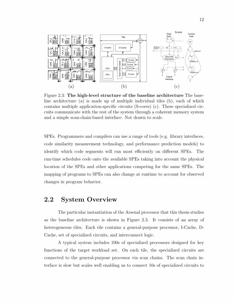
Figure 2.3: The high-level structure of the baseline architecture The base-line architecture (a) is made up of multiple individual tiles (b), each of whichcontains multiple application-specific circuits (S-cores) (c). These specialized cir-cuits communicate with the rest of the system through a coherent memory systemand a simple scan-chain-based interface. Not drawn to scale.
SPEs. Programmers and compilers can use a range of tools (e.g. library interfaces,
code similarity measurement technology, and performance prediction models) to
identify which code segments will run most efficiently on different SPEs. The
run-time schedules code onto the available SPEs taking into account the physical
location of the SPEs and other applications competing for the same SPEs. The
mapping of programs to SPEs can also change at runtime to account for observed
changes in program behavior.
2.2 System Overview
The particular instantiation of the Arsenal processor that this thesis studies
as the baseline architecture is shown in Figure 2.3. It consists of an array of
heterogeneous tiles. Each tile contains a general-purpose processor, I-Cache, D-
Cache, set of specialized circuits, and interconnect logic.
A typical system includes 100s of specialized processors designed for key
functions of the target workload set. On each tile, the specialized circuits are
connected to the general-purpose processor via scan chains. The scan chain in-
terface is slow but scales well enabling us to connect 10s of specialized circuits to

13
the general-purpose processor. The specialized circuits share the D-Cache with
the general-purpose processor, ensuring coherent memory between the two by con-
struction.
This architecture achieves much of its energy efficiency compared to a con-
ventional tiled architecture system by offloading computations onto these special-
ized circuits. These circuits are automatically designed using a C-to-hardware
compiler (Section 2.3) and achieves significant energy efficiency (up to 40×) com-
pared to a general-purpose processor.
2.2.1 Specialized Processor Hardware Design
This section describes in detail the architecture of the specialized circuits
including their datapath, control unit, cache interface, and scan chain interface to
the CPU.
Datapath and Control Unit By design, the datapath and control unit of the
specialized circuits very closely resembles the data and control flow of the target
source code in Single static assignment form [CFR+89]. The datapath contains
functional units (adders, shifters, etc.) for the arithmetic operations, muxes to
implement control decisions and phi [CFR+89] nodes, and registers to hold program
values across clock cycles.
The control unit implements a state machine that mimics the control flow
of the code. It tracks branch outcomes to determine which state to enter on each
cycle. The control unit sets the enable and select lines on the registers and muxes
so that the correct basic block is active each cycle.
The close correspondence between the program’s structure and the corre-
sponding specialized circuit enables them to support almost arbitrary source code
including struct, union, pointers, and most control flow constructs. This design
model fits well with the higher level goals of this thesis to provide energy-efficient
execution for irregular, hard to parallelize integer applications.

14
computeArraySum{ sum = 0; for(i = 0; i < n; i++) { sum += a[i]; } return(sum);}
i = 0sum = 0
phi(i)phi(sum)
i < n
sum+=a[i]i++ return(sum)
F
(a) (b) (c)
isum a
+
ld unitaddr
valid
en
value+
0 0
+1
muxSelmuxSel
ldEn
ldValid
<
n
cond
Data Path
sInit
s1
s2
s3 ldValid==0
sRetcond==0
Control Path
Cache Interface
Scan ChainInterface
Scan Chain
Figure 2.4: Specialized Core Design Example An example showing the trans-lation from C code (a), to the compiler’s internal representation (b), and finally tohardware (c). The hardware schematic and state machine correspond very closelyto the data and control flow graphs of the C code.
Memory interface and ordering The specialized circuits execute the memory
operations sequentially in the program order to ensure correctness. The specialized
circuits contain a load/store unit for each memory operation in the target source
code and these units connect to the processor’s L1 data cache, guaranteeing a co-
herent memory system between the specialized circuit and CPU by construction.
For executing a memory operation, the load/store unit sends a “request” signal
along with the memory address/value to the L1 data cache and stalls the execu-
tion of the specialized processor until it receives the “valid” signal from the cache
signaling the completion of the memory operation.
Example Figure 2.4(a)-(c) shows a sample source code, its control flow graph,
and the corresponding hardware design for it. The hardware corresponds very
closely to the CFG of the sample code. The datapath has muxes corresponding
to the phi operators in the CFG. Also, the control unit is almost identical to
the CFG, with additional self-loops for memory operations (and other multi-cycle
operations). The datapath has a load unit to access the memory hierarchy to read
the array a.

15
2.2.2 The CPU/Specialized-processor Interface
The specialized circuits are connected to the CPU via a set of scan chains.
They receive the initial arguments as well as the “ready” signal from the CPU
using these scan chains. The initial arguments are the live-in values for the com-
putation being off-loaded to the specialized circuit and the ready signal signals the
beginning of the execution. When the specialized circuits complete the off-loaded
computation, they send a “done” signal to the CPU.
2.2.3 The Runtime System
When compiling an application containing functions that can be off-loaded
to a specialized processor, the compiler will insert stubs that enable the application
to choose between using the specialized processor or the CPU at runtime.
At runtime, when an application wants to run a function that has the
corresponding specialized circuit available, it queries the runtime to get access to
the specialized processor. If the specialized processor is available, the application
uses the scan chain interface to pass the initial arguments, start it running, and
then waits for execution to complete. When the done signal is raised by the
specialized processor, control passes back to the stub code which extracts the
return value and passes it back to the application.
If the specialized processor is not available, then the application uses the
CPU version of the function code to continue execution on the general-purpose
processor.
2.3 Methodology
This section presents the details of the toolchain for automatically gener-
ating the hardware for specialized cores from the application code as well as the
methodology for the performance and power measurements of the baseline system.

16
Target Application
HotspotIdentification
BTL Simulator
VCS + PrimeTime
Synopsys CAD Tool Flow
Source Code
C Code
Verilog
Placed and RoutedCircuit Memory Trace
C to Verilog
Performance ResultsPower Results
C specification
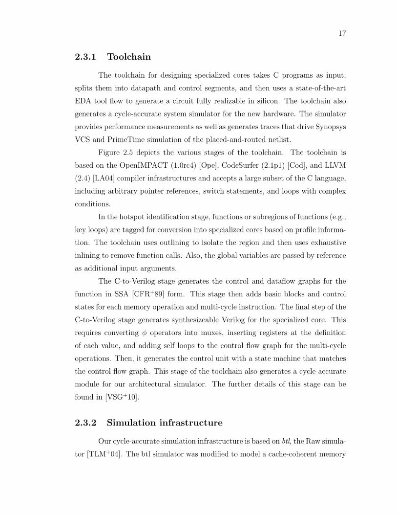
Figure 2.5: The C-to-hardware toolchain The various stages of our toolchaininvolved in hardware generation, simulation, and power measurement are shown.
17
2.3.1 Toolchain
The toolchain for designing specialized cores takes C programs as input,
splits them into datapath and control segments, and then uses a state-of-the-art
EDA tool flow to generate a circuit fully realizable in silicon. The toolchain also
generates a cycle-accurate system simulator for the new hardware. The simulator
provides performance measurements as well as generates traces that drive Synopsys
VCS and PrimeTime simulation of the placed-and-routed netlist.
Figure 2.5 depicts the various stages of the toolchain. The toolchain is
based on the OpenIMPACT (1.0rc4) [Ope], CodeSurfer (2.1p1) [Cod], and LLVM
(2.4) [LA04] compiler infrastructures and accepts a large subset of the C language,
including arbitrary pointer references, switch statements, and loops with complex
conditions.
In the hotspot identification stage, functions or subregions of functions (e.g.,
key loops) are tagged for conversion into specialized cores based on profile informa-
tion. The toolchain uses outlining to isolate the region and then uses exhaustive
inlining to remove function calls. Also, the global variables are passed by reference
as additional input arguments.
The C-to-Verilog stage generates the control and dataflow graphs for the
function in SSA [CFR+89] form. This stage then adds basic blocks and control
states for each memory operation and multi-cycle instruction. The final step of the
C-to-Verilog stage generates synthesizeable Verilog for the specialized core. This
requires converting φ operators into muxes, inserting registers at the definition
of each value, and adding self loops to the control flow graph for the multi-cycle
operations. Then, it generates the control unit with a state machine that matches
the control flow graph. This stage of the toolchain also generates a cycle-accurate
module for our architectural simulator. The further details of this stage can be
found in [VSG+10].
2.3.2 Simulation infrastructure
Our cycle-accurate simulation infrastructure is based on btl, the Raw simula-
tor [TLM+04]. The btl simulator was modified to model a cache-coherent memory

18
among multiple processors, to include a scan chain interface between the CPU and
all of the local specialized cores, and to simulate the specialized logic itself.
2.3.3 Synthesis
For synthesis, the toolchain targets a TSMC 45 nm GS process using Syn-
opsys Design Compiler (C-2009.06-SP2) and IC Compiler (C-2009.06-SP2). Our
toolchain generates synthesizeable Verilog and automatically processes the design
in the Synopsys CAD tool flow, starting with netlist generation and continuing
through placement, clock tree synthesis, and routing, before performing post-route
optimizations.
2.3.4 Power measurements
In order to measure the power usage of specialized cores, the btl simulator
periodically samples execution by storing traces of all inputs and outputs to the
specialized logic. Each sample starts with a “snapshot” recording the entire register
state of the specialized core and continues for 10,000 cycles. The current sampling
policy is to sample 10,000 out of every 50,000 cycles, and we discard sampling
periods corresponding to the initialization phase of the application.
The power measurement stage feeds each trace sample into the Synopsys
VCS (C-2009.06) logic simulator. Along with the Verilog code our toolchain also
automatically generates a Verilog testbench module, which initiates the simulation
of each sample by scanning in the register values from each trace snapshot. The
VCS simulation generates a VCD activity file, which we pipe as input into Synopsys
PrimeTime (C-2009.06-SP2). PrimeTime computes both the static and dynamic
power for each sampling period.
To model power for other system components, this stage uses processor
and clock power values from specifications for a MIPS 24KE processor in TSMC
90 nm and 65 nm processes [MIP09], and component ratios for Raw reported
in [KTMW03], scaled to a 45 nm process. For its measurements, this stage assumes
a MIPS core frequency of 1.5 GHz with 0.077 mW/MHz for average CPU operation.

19
Finally, this stage uses CACTI 5.3 [TMAJ08] for I- and D-cache power.
Acknowledgments
Portions of this research were funded by the US National Science Founda-
tion under NSF CAREER Awards 06483880 and 0846152, and under NSF CCF
Award 0811794.
This chapter contains material from “Conservation cores: reducing the
energy of mature computations”, by Ganesh Venkatesh, Jack Sampson, Nathan
Goulding, Saturnino Garcia, Vladyslav Bryksin, Jose Lugo-Martinez, Steven Swan-
son and Michael Bedford Taylor, which appears in ASPLOS ’10: Proceedings of the
fifteenth edition of ASPLOS on Architectural support for programming languages
and operating systems. The dissertation author was the primary investigator and
author of this paper. The material in this chapter is copyright c©2010 by the Asso-
ciation for Computing Machinery, Inc. (ACM). Permission to make digital or hard
copies of part or all of this work for personal or classroom use is granted without
fee provided that the copies are not made or distributed for profit or commercial
advantage and that copies bear this notice and the full citation on the first page in
print or the first screen in digital media. Copyrights for components of this work
owned by others than ACM must be honored. Abstracting with credit is permit-
ted. To copy otherwise, to republish, to post on servers, or to redistribute to lists,
requires prior specific permission and/or a fee. Request permissions from Publica-
tions Dept., ACM, Inc., fax +1 (212) 869-0481, or email [email protected].

Chapter 3
Patchable Conservation Cores:
Energy-efficient circuits with
processor-like lifetimes
Chapter 1 explains the utilization wall phenomenon and the challenges it
presents in effectively using the increasing transistor counts to scale performance.
The previous chapter described the Arsenal system, a massively heterogeneous
tiled architecture that seeks to scale performance in spite of the utilization wall by
synthesizing application-specific circuits targeting the key functions of the system
workload. These application-specific circuits provide energy-efficient execution of
irregular integer codes and can improve the energy efficiency by up to 30X com-
pared to an efficient in-order MIPS processor [TLM+04]. These specialized circuits
enable the Arsenal system to optimize energy-per-computation, which translates
into better system performance by allowing more computations to run in parallel.
However, these application-specific circuits are very tightly coupled to the
source code they target and cannot support any change in the same. Hence, these
circuits are tied to the version of the application they were designed for and cannot
support older or newer application versions. This lack of flexibility makes these
application-specific circuits poor candidates for many of the applications in a sys-
tem’s workload. From a system designer’s standpoint, designing co-processors that
can only target a particular version of an application can cause two main prob-
20

21
lems – these specialized circuits would become unusable as soon as the application
version is upgraded and also, circuits targeting the latest version will provide little
benefit to the users still using the older application versions.
To address these issues, this thesis proposes Patchable Conservation cores
(C-cores), application-specific circuits that remain useful across application ver-
sions, providing them with lifetimes comparable to those of general-purpose pro-
cessors. The main contribution of this work is the novel patching mechanism that
provides these application-specific circuits with targeted reconfigurability to enable
them to support multiple application versions. This work extends the toolchain
presented in the previous section to generate configuration “patches” corresponding
to different application versions. At runtime, the c-core utilizes the configuration
patch to adapt to the application version that wants to run on it. In this manner,
c-cores remain useful across application versions, providing them with lifetimes
comparable to that of a general-purpose processor.
This chapter is organized as follows. Section 3.1 motivates the need for
reconfigurability in application-specific circuits. Section 3.2 describes the recon-
figurability mechanisms that this work proposes to improve the longevity of these
specialized circuits. Section 3.3 explains that patching algorithm for mapping
alternate application versions onto a patchable c-core. Section 3.4 presents the
methodology for designing and configuring the patchable c-cores. Section 3.5 eval-
uates the energy efficiency and longevity of patchable c-cores. Section 3.6 analyzes
the area and energy overheads of the reconfigurability mechanisms and proposes
optimizations to mitigate them without affecting the c-core’s longevity. Section 3.7
proposes a mechanism to further improve the backward compatibility of the patch-
able c-cores. Section 3.8 concludes this chapter.
3.1 Case for Reconfigurability in Application
Specific Circuits
This work seeks to provide energy-efficient execution for mature applica-
tions, applications that have a relatively stable set of core functions. While the code

22
base of these applications will change across versions, the source code correspond-
ing to the core functionality changes very infrequently, and when it does change, the
changes tend to be relatively minor. This section analyzes the changes in the core
functions of mature applications across successive versions and uses that analysis
to motivate the need for providing targeted reconfigurability in application-specific
circuits.
To better understand how the core functions change in mature applica-
tions, this section analyzes the changes across successive versions of DJPEG,
CJPEG, Libpng, Sat Solver, MCF, VPR, and Bzip2 and documents the code
change patterns that were commonly seen. Figure 3.1 shows the commonly seen
code change pattern. The analysis shows that supporting these changes would
allow the application-specific circuits to adapt to multiple versions of the applica-
tions listed above, potentially enabling these configurable circuits to remain useful
for eight years on average. These commonly seen source code change patterns are
summarized below.
Control flow changes A commonly seen change in the key functions is the
addition or removal of certain computations. Figure 3.1(a) shows the changes
in the function refresh_potential across versions SPEC2000 and SPEC2006 of
MCF. The main change across the two versions is the removal of a for loop in the
beginning of the function, and the rest of the function code remains the same.
Changes in datapath operators and constants The second kind of common
change patterns includes changes in expression constants and changes in datapath
operators such as loop termination conditions (< replaced by ≤). Figure 3.1(b)
shows the changes in the function sentMTFValues across versions 1.0.2 and 1.0.3
of Bzip2. The only change across the two versions is in the constant value used to
ensure that a program variable value lies within the valid range.
Changes in the memory layout Another form of commonly seen change is in
the layout of the program data structures. These changes include addition, deletion
or rearrangement of structure fields. Figure 3.1(c) shows the changes in the data

23
long refresh_potential( network_t *net ){ node_t *stop = net->stop_nodes; node_t *node, *tmp; node_t *root = net->nodes; long checksum = 0;
for( node = root, stop = net->stop_nodes; node < (node_t*)stop; node++ ) node->mark = 0;
root->potential = (cost_t) -MAX_ART_COST; tmp = node = root->child; while( node != root ) { ... }
...
return checksum;}
MCF SPEC2000
long refresh_potential( network_t *net ){ node_t *node, *tmp; node_t *root = net->nodes; long checksum = 0;
root->potential = (cost_t) -MAX_ART_COST; tmp = node = root->child; while( node != root ) { ... }
...
return checksum;}
MCF SPEC2006(a)
void sendMTFValues(Estate *s){ ... /*--- Assign actual codes for the tables. --*/ for (t = 0; t < nGroups; t++) { minLen = 32; maxLen = 0; for (i = 0; i < alphaSize; i++) { if (s->len[t][i] > maxLen) maxLen = s->len[t][i]; if (s->len[t][i] < minLen) minLen = s->len[t][i]; } AssertH ( !(maxLen > 20 ), 3004 ); AssertH ( !(minLen < 1), 3005 ); BZ2_hbAssignCodes ( &(s->code[t][0]), &(s->len[t][0]), minLen, maxLen, alphaSize ); } ...}
BZIP2 v1.0.2
void sendMTFValues(Estate *s){ ... /*--- Assign actual codes for the tables. --*/ for (t = 0; t < nGroups; t++) { minLen = 32; maxLen = 0; for (i = 0; i < alphaSize; i++) { if (s->len[t][i] > maxLen) maxLen = s->len[t][i]; if (s->len[t][i] < minLen) minLen = s->len[t][i]; } AssertH ( !(maxLen > 17 /*20*/ ), 3004 ); AssertH ( !(minLen < 1), 3005 ); BZ2_hbAssignCodes ( &(s->code[t][0]), &(s->len[t][0]), minLen, maxLen, alphaSize ); } ...}
BZIP2 v1.0.3(b)
struct jpeg_decompress_struct { struct jpeg_source_mgr * src;
JDIMENSION image_width; JDIMENSION image_height; double output_gamma; boolean raw_data_out;
boolean quantize_colors; ...}
DJPEG v5
struct jpeg_decompress_struct { struct jpeg_source_mgr * src; JDIMENSION image_width; JDIMENSION image_height; double output_gamma; boolean buffered_image; boolean raw_data_out; J_DCT_METHOD dct_method; boolean do_fancy_upsampling; boolean do_block_smoothing; boolean quantize_colors; ...}
DJPEG v6(c)
Figure 3.1: Commonly seen source code modification patterns across ap-plication versions The figure shows changes across versions of a) MCF, b) Bzip2,and c) DJPEG. The changes are shown in bold.

24
structure jpeg_decompress_struct across versions 5.0 and 6.0 of DJPEG. The
data structure’s member variables are reorganized and new variables are added
(for ex. buffered_image). While the source of the hot spot functions in DJPEG
does not change across versions, the change in the data structure layout changes
the offsets used to calculate the memory addresses for load/store operations.
The above analysis shows that while the source code for the key functions
might change across application versions, the majority of the code in a key function
tends to remain the same. Hence, across application versions, hardware implemen-
tation is available for the majority of the code in a key function and the new version
should ideally be able to reuse the available hardware, albeit at a lower level of
performance/energy efficiency.
3.2 Reconfigurability support in Conservation
Cores
The analysis of successive application versions, presented in the previous
section, revealed a number of common change patterns, all of which were relatively
minor changes in source code. As discussed in Section 2.2.1, the c-core control unit
and datapath very closely correspond to the program structure. Hence, the changes
in c-core hardware design would mirror the changes in the source code. Fortunately,
c-cores can support many of these changes effectively with very modest amounts
of reconfigurability. This thesis proposes the following three patching mechanisms
for adjusting the c-core behavior after they have been fabricated.
Configurable constants The first patching mechanism generalizes hard-coded
immediate values into configurable registers. This mechanism supports changes to
the values of compile-time constants and the insertion, deletion, or rearrangement
of structure fields.
Generalized single-cycle datapath operators To support the replacement
of one operator with another, the second patching mechanism generalizes any

25
addition or subtraction to an adder-subtractor, any comparison operation to a
generalized comparator, and any bitwise operation to a bitwise ALU. A small
configuration register is then added for each such operator, determining which
operation is currently active.
Control flow changes In order to handle changes in the CFG’s structure and
changes to basic blocks that go beyond what the above mechanisms can handle, the
third patching mechanism provides a flexible exception mechanism. The control
path contains a bit for each state transition that determines whether the c-core
should treat it as an exception.
When the state machine makes an exceptional transition, the c-core stops
executing and transfers control to the general-purpose core. The exception handler
extracts current variable values from the c-core via the scan-chain-based interface,
performs a portion of the patched execution, transfers new values back into the
c-core, and resumes execution. The exception handler can restart c-core execution
at any point in the CFG, so exceptions can arbitrarily alter control flow and/or
replace arbitrary portions of the CFG.
The next section describes the patch generation algorithm for mapping the
newer application versions onto a patchable c-core. The patching algorithm utilizes
this mapping to determine the reconfiguration state necessary to allow a c-core to
continue to run code even after it has been changed from the version used to
generate that c-core.
3.3 Patching Algorithm
This section describes the patching algorithm this thesis proposes. The
patching algorithm works directly on the program’s dataflow and control flow
graph, a representation that can be generated from either source code or a compiled
binary. This enables the patch generation to happen at assembly level, allowing
the new application versions to run on the specialized hardware without any source
code modifications.

26
Original VersionsumArray(int n, int*a){ int i = 0; int sum = 0; for(;i<n;i++) { sum += a[i]; }
return(sum);}
New VersionsumArray(int n, int*a){ int i = 0; int sum = 0; for(;i<n;i++) { sum += a[i]; } sum = sum % 256; return(sum);}
(a) (b)
FT
Jump to appropriate
basic block
Exception to Sw on False Edge
i = 0;sum = 0
sum += a[i];i++
i<n
return sum to SW
Prologue: Scan in sum
Patch Code: sum = sum % 256
Epilogue: Scan sum to c-core
Control Flow Graph of C-Core for
sumArray Exception Patch
(c)
F
T
i = 0;sum = 0
sum += a[i];i++
i<n
return sum to SW
Control Flow Graph of sumArray (Original Version)
FT
i = 0;sum = 0
sum += a[i];i++
i<n
sum = sum%256
Control Flow Graph of sumArray
(New Version)
return sum to SW
Har
dwar
e R
egio
n 1
Har
dwar
e R
egio
n 2
Softw
are
Reg
ion
Control Flow Mapping
Figure 3.2: Handling changes in control flow across versions (a) The originaland new source for sumArray() is shown. (b) The mapping between the new andthe original version of sumArray’s CFG covers most of the target version in twohardware regions. (c) Transfers of control between the hardware and softwareregions require an exception.

27
R2 R5 R3
+ *
R1 R4
R13 R15 R12
-*
R14 R11
Match
R22 R25 R23
+ *
R21 R24
R26
No Match
B1
B2 B3
Figure 3.3: Basic block matching Target block B3 can be mapped onto thehardware for original block B1, but target block B2 does not match B1 and cannotbe mapped: There is no consistent mapping between the register names in bold.
When a c-core-equipped processor ships, it can run the latest version, re-
ferred to as the original version, of the targeted applications without modification.
When a new version of an application becomes available, the patching algorithm
determines how to map the new version of the software, referred to as the target
version, onto the existing c-core hardware. The goal of the patching process is to
generate a patch for the original hardware that will let it run the target software
version.
The patching algorithm proceeds in four stages: basic block mapping, con-
trol flow mapping, register remapping, and patch generation.
3.3.1 Basic block mapping
The first stage of the algorithm identifies which hardware basic blocks in
the original hardware can run each basic block in the target application. Since
the original hardware includes generalized arithmetic operators and configurable
constant registers, there is significant flexibility in what it means for two basic
blocks to match. Two basic blocks match if the following conditions are true.

28
• The basic blocks have the same number of instructions, not including uncon-
ditional jumps (which only affect the control path and, therefore, have no
effect on the generated hardware).
• The data flow graphs of the two basic blocks are isomorphic up to operators
at the nodes and constant values.
• For each instruction in the target basic block, there is a corresponding in-
struction in the original that it is compatible with. That is, the original
instruction is either identical to the target, or can be patched to turn it into
the target instruction.
Figure 3.3 shows one original block, B1 and two target blocks, B2 and B3.
The mapping process will mark B3 as a possible match for B1, and B2 as not
matching B1.
3.3.2 Control flow mapping
The next step of the patching algorithm is building a map between the
control flow graphs of the original and target versions. This step identifies regions
of the target control flow graph that map perfectly onto disjoint portions of the
original hardware. These portions of the function are called hardware regions, and
they will execute entirely in hardware under the patch. Ideally, all basic blocks
in the target will map to basic blocks in the original, and there will be a single
hardware region. In practice this will sometimes not be possible. The target
version may have basic blocks inserted or deleted relative to the original, or one of
the basic blocks may have changed enough that no matching basic block exists in
the original. The exception mechanism executes the remaining, unmapped software
regions on the general purpose processor.
To divide the control flow graph, the algorithm starts by matching the
entry node of the target graph with the entry of the original graph. The algorithm
proceeds with a breadth-first traversal of the target graph, greedily adding as many
blocks to the hardware region as possible. When the hardware region can grow no
larger, the region is complete.

29
A region stops growing for one of two reasons: It may reach the end of
the function or run up against another hardware region. Alternatively, there may
be no matching basic blocks available to add to the region because of a code
modification. In that case, the patching algorithm marks the non-matching basic
blocks as part of the software region and selects the lowest depth matching basic
block available to seed the creation of a new hardware region. This stage of the
algorithm terminates when the entire function has been partitioned into hardware
regions and software regions.
Figure 3.2 illustrates this portion of the algorithm. Figure 3.2(a) shows the
original software version of a function called sumArray() and its CFG. Figure 3.2(b)
shows the target version of sumArray() which has an extra operation. Most of the
new sumArray() is mapped onto the original c-core in two hardware regions, but
the new operation is mapped to a separate software region because the hardware
for it does not exist in the original c-core. Any transition to this region will be
marked as an exception.
3.3.3 Register mapping
The next phase of the algorithm generates a consistent local mapping be-
tween registers in the original and target basic block for each matched basic block
pair. In this mapping, the output of the first instruction in the original basic block
corresponds to the output of the first instruction in the target basic block, and so
on.
The next step is to combine these per-block maps to create a consistent
register mapping for each hardware region. To construct the mapping, the patch-
ing algorithm analyzes the basic block mapping for each of the basic blocks in the
region. This data yields a weighted bipartite graph, in which one set of nodes
corresponds to the register names from the original code and the second set corre-
sponds to register names from the target code. An edge exists between an original
register, r1, and a target register, r2, if there exits a basic block pair that maps
r2 onto r1. The weight of the edge is the number of basic block pairs that contain
this register mapping.
30
Patching Enabled Compiler
Original Version
C-core Identification
Configuration Generator
BTL Simulator
VCS + PrimeTime
Synopsys CAD Tool Flow
Source Code
C-core Code
HW Spec in CVerilog
Placed and RoutedCircuit
Memory Trace
New Version
C-core Identification
C-core Code
Patching Algorithm
3 Address Code
Fully Configured HW
Source Code
C to Verilog C to Binary
Performance ResultsPower Results
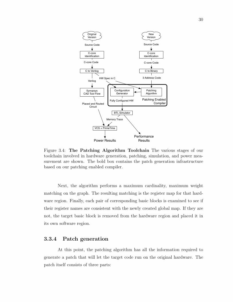
Figure 3.4: The Patching Algorithm Toolchain The various stages of ourtoolchain involved in hardware generation, patching, simulation, and power mea-surement are shown. The bold box contains the patch generation infrastructurebased on our patching enabled compiler.
Next, the algorithm performs a maximum cardinality, maximum weight
matching on the graph. The resulting matching is the register map for that hard-
ware region. Finally, each pair of corresponding basic blocks is examined to see if
their register names are consistent with the newly created global map. If they are
not, the target basic block is removed from the hardware region and placed it in
its own software region.
3.3.4 Patch generation
At this point, the patching algorithm has all the information required to
generate a patch that will let the target code run on the original hardware. The
patch itself consists of three parts:

31
• the configuration bits for each of the configurable components including the
datapath elements and the configurable constant registers
• exception bits for each of the control flow edges that pass from a hardware
region into a software region
• code to implement each of the software regions
The software region code is subdivided into three sections. First, the pro-
logue uses the scan chain interface to retrieve values from the c-core’s datapath
into the processor core. Next, the patch code implements the software region. The
region may have multiple exit points, each leading back to a different point in the
datapath. At the exit, the epilogue uses the scan chain interface again to insert
the results back into the datapath and return control to the c-core.
3.3.5 Patched execution example
Figure 3.2(c) shows how c-cores use the exception mechanism to patch
around software regions generated during the control flow mapping stage. When
the c-core execution reaches the false edge of the for loop condition, it makes an
exceptional transition which freezes the c-core and transfers control to the CPU.
The CPU retrieves the application’s software exception handler corresponding to
the edge that raised the exception, and the handler executes the prologue, patch
code, and epilogue before returning control to the c-core.
3.4 Methodology
This section describes the methodology for designing patchable c-cores and
generating configuration patches corresponding to different application versions.
The bold box in Figure 3.4 shows how the patching system fits into the toolchain
explained in Section 2.3.

32
3.4.1 Generation of Patchable Conservation Core
Hardware
The hardware generation compiler extends the C-to-Verilog compiler (Sec-
tion 2.3.1) to provide support for the reconfigurability mechanisms. The hardware
compiler instantiates the datapath operators in the program as generalized ALUs,
stores the expression constants and memory offsets in 32-bit registers, and extends
each state transition edge in the control unit with a 1-bit exception register.
Also, the hardware compiler adds two new groups of scan chains to c-cores.
The first group of scan chains connects all of the reconfiguration state including the
exception registers, registers for storing configurable constants and memory offsets,
and the configuration registers in each of the generalized datapath operators. This
scan chain group is used to initialize the c-core with the configuration patch before
the application execution begins. The second group of scan chains connects the
registers storing the datapath state. These datapath scan chains allow the CPU
to manipulate arbitrary state during an exception. Since each c-core can contain
hundreds of registers, the datapath state registers are divided amongst up to 32
scan chains to ensure that CPU can access the datapath state without significant
overhead.
3.4.2 Generating Configuration Patch
The toolchain generates the application configuration patch to store the
reconfiguration state. This includes the exception register values, expression con-
stant and memory offset values, and operator index values in the ALU configuration
registers. This stage stores the configuration patch in a binary file. At runtime,
the application reads this configuration patch file to initialize the c-core using the
scan chain interface explained in the previous section.
Figure 3.4 shows how the configuration patch is generated for new applica-
tion releases. The toolchain generates the configuration patch by matching the new
application version’s binary to the c-core hardware design based on the patching
algorithm described in Section 3.3.

33
3.5 Results
This section describes the performance and efficiency of the patchable c-core
architecture and its impact on application performance and energy consumption.
Also, this section discusses the gains in longevity due to the patching mechanism.
3.5.1 Energy savings
This section presents the analysis of patchable c-cores for six versions of
bzip2 (1.0.0−1.0.5), and two versions each of cjpeg (v1−v2), djpeg (v5−v6), mcf
(2000−2006), and vpr (4.22−4.30). Table 3.1 summarizes the c-cores. The table
shows that the hot spots of the above-mentioned benchmarks vary greatly in size
as well as complexity. Also, the data shows that the same set of functions accounts
for a sizable fraction of execution of different application versions, implying that
the c-cores will remain useful across application version releases.
Figure 3.5 shows the relative energy efficiency, EDP improvement, and
speedup of c-cores versus a MIPS processor executing the same code. For fair-
ness, and to quantify the benefits of converting instructions into c-cores, we ex-
clude cache power for both cases. The data show that patchable c-cores are up to
15.96× as energy-efficient as a MIPS core at executing the code they were built to
execute. The data also shows that the c-cores are able to support multiple versions
effectively. On average, the c-cores are 8.68× more energy-efficient than a MIPS
core at executing alternate versions of the code they were designed to execute. The
non-patchable c-cores are even more energy efficient, but their inability to adapt
to software changes limits their useful lifetime.
Figure 3.6 shows the energy delay improvements provided by a c-core-
enabled architecture at the application level. This is a full system evaluation
including the runtime and CPU/c-core interface overheads and the energy con-
sumed by the memory hierarchy and interconnect. The data shows that the c-
core-enabled architecture improves the energy efficiency by 33% on average com-
pared to the baseline tiled architecture. Moreover, in a c-core-enabled system,
the dynamic energy of computation accounts for less than half of the total energy

34
Table 3.1: Conservation core statistics The c-cores we generated vary greatlyin size and complexity. In the “Key” column, the letters correspond to applicationversions and the Roman numerals denote specific functions from the applicationthat a c-core targets. “LOC” is lines of C source code, and “% Exe.” is thepercentage of execution that each function comprises in the application.
C-core Ver. Key LOC % Exe.Area (mm2) Freq. (MHz)Non-P. Patch. Non-P. Patch.
bzip2fallbackSort 1.0.0 A i 231 71.1 0.128 0.275 1345 1161fallbackSort 1.0.5 F i 231 71.1 0.128 0.275 1345 1161
cjpegextract MCUs v1 A i 266 49.3 0.108 0.205 1556 916
get rgb ycc rows v1 A ii 39 5.1 0.020 0.044 1808 1039subsample v1 A iii 40 17.7 0.023 0.039 1651 1568
extract MCUs v2 B i 277 49.5 0.108 0.205 1556 916get rgb ycc rows v2 B ii 37 5.1 0.020 0.044 1808 1039
subsample v2 B iii 36 17.8 0.023 0.039 1651 1568djpeg
jpeg idct islow v5 A i 223 21.5 0.133 0.222 1336 932ycc rgb convert v5 A ii 35 33.0 0.023 0.043 1663 1539jpeg idct islow v6 B i 236 21.7 0.135 0.222 1390 932ycc rgb convert v6 B ii 35 33.7 0.024 0.043 1676 1539
mcfprimal bea mpp 2000 A i 64 35.2 0.033 0.077 1628 1412refresh potential 2000 A ii 44 8.8 0.017 0.033 1899 1647primal bea mpp 2006 B i 64 53.3 0.032 0.077 1568 1412refresh potential 2006 B ii 41 1.3 0.015 0.028 1871 1639
vprtry swap 4.22 A i 858 61.1 0.181 0.326 1199 912try swap 4.3 B i 861 27.0 0.181 0.326 1199 912
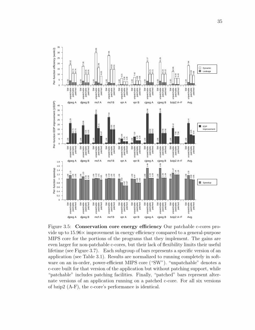
35
�� S
W� u
npat
chab
le� p
atch
able
� pat
ched ��
� S
W�
unpa
tcha
ble
� pa
tcha
ble
� pa
tche
d��� � S
W�
unp
atch
able
� p
atch
able
� p
atch
ed���
� � S
W�
unp
atch
able
� p
atch
able
� p
atch
ed���
�� �
SW
�
unpa
tcha
ble
�
patc
habl
e�
pa
tche
d���
����
S
W�
u
npat
chab
le�
p
atch
able
�
pat
ched
������
��
S
W�
u
npat
chab
le�
p
atch
able
�
pat
ched
������
���
SW
�
un
patc
habl
e�
patc
habl
e�
patc
hed
������
����
SW
�
u
npat
chab
le�
pat
chab
le�
pat
ched
������
����
������
�����
�
S
W�
unp
atch
able
�
p
atch
able
�
p
atch
ed
Per
−fu
nctio
n ef
ficie
ncy
(wor
k/J)
0
5
10
15
20
25
30
35
1.00
18.5
210
.74
10.7
4
1.00
17.3
010
.01
10.0
1
1.00
29.8
615
.96
8.53
1.00
27.0
514
.63
14.5
1
1.00
6.21
3.38
3.38
1.00
7.42
4.08
4.08
1.00
21.1
710
.21
10.2
1
1.00
21.2
510
.22
10.2
2
1.00
12.6
56.
436.
43
1.00
17.9
49.
528.
68
djpeg A�
�
��
djpeg B�
�
��
� mcf A�
�
�
�
� mcf B�
�
� �
� vpr A�
���
� vpr B�
���
cjpeg A�
�
��
cjpeg B�
�
��
bzip2 A−F Avg.�
�
��
�� �
�
� �
Dynamic
Leakage
�� S
W� u
npat
chab
le� p
atch
able
� pat
ched ��
� S
W�
unpa
tcha
ble
� pa
tcha
ble
� pa
tche
d��� � S
W�
unp
atch
able
� p
atch
able
� p
atch
ed���
� � S
W�
unp
atch
able
� p
atch
able
� p
atch
ed���
�� �
SW
�
unpa
tcha
ble
�
patc
habl
e�
pa
tche
d���
����
S
W�
u
npat
chab
le�
p
atch
able
�
pat
ched
������
��
S
W�
u
npat
chab
le�
p
atch
able
�
pat
ched
������
���
SW
�
un
patc
habl
e�
patc
habl
e�
patc
hed
������
����
SW
�
u
npat
chab
le�
pat
chab
le�
pat
ched
������
����
������
�����
�
S
W�
unp
atch
able
�
p
atch
able
�
p
atch
edPer
−fu
nctio
n E
DP
impr
ovem
ent (
1/E
DP
)
0
5
10
15
20
25
30
35
40
1.00
21.2
910
.73
10.7
3
1.00
18.9
69.
339.
33
1.00
30.5
316
.11
8.07
1.00
27.5
414
.65
14.5
6
1.00
5.09
2.25
2.25
1.00
7.23
3.28
3.28
1.00
31.5
810
.52
10.5
2
1.00
31.8
910
.58
10.5
8
1.00
16.1
27.
587.
58
1.00
21.1
49.
458.
54
djpeg A�
�
��
djpeg B�
�
��
� mcf A�
�
�
�
� mcf B�
�
� �
� vpr A�
���
� vpr B�
���
cjpeg A�
�
��
cjpeg B�
�
��
bzip2 A−F Avg.�
�
��
�� �
�
� �
EDPImprovement
�� S
W� u
npat
chab
le� p
atch
able
� pat
ched ��
� S
W�
unpa
tcha
ble
� pa
tcha
ble
� pa
tche
d��� � S
W�
unp
atch
able
� p
atch
able
� p
atch
ed���
� � S
W�
unp
atch
able
� p
atch
able
� p
atch
ed���
�� �
SW
�
unpa
tcha
ble
�
patc
habl
e�
pa
tche
d���
����
S
W�
u
npat
chab
le�
p
atch
able
�
pat
ched
������
��
S
W�
u
npat
chab
le�
p
atch
able
�
pat
ched
������
���
SW
�
un
patc
habl
e�
patc
habl
e�
patc
hed
������
����
SW
�
u
npat
chab
le�
pat
chab
le�
pat
ched
������
����
������
�����
�
S
W�
unp
atch
able
�
p
atch
able
�
p
atch
ed
Per
−fu
nctio
n sp
eedu
p
0
0.2
0.4
0.6
0.8
1
1.2
1.4
1.6
1.8
1.00
1.15
1.00
1.00
1.00 1.
100.
930.
93 1.00 1.02
1.01
0.95 1.
001.
021.
001.
00
1.00
0.82
0.67
0.67
1.00
0.97
0.80
0.80
1.00
1.49
1.03
1.03
1.00
1.50
1.04
1.04
1.00
1.27
1.18
1.18
1.00
1.15
0.96
0.95
djpeg A
��
��
djpeg B
��
��
� mcf A
� � � �
� mcf B
� � � �
� vpr A
��
��
� vpr B
� ���
cjpeg A
�
�
��
cjpeg B
�
�
��
bzip2 A−F Avg.
�
���
��
��
� �
Speedup
Figure 3.5: Conservation core energy efficiency Our patchable c-cores pro-vide up to 15.96× improvement in energy efficiency compared to a general-purposeMIPS core for the portions of the programs that they implement. The gains areeven larger for non-patchable c-cores, but their lack of flexibility limits their usefullifetime (see Figure 3.7). Each subgroup of bars represents a specific version of anapplication (see Table 3.1). Results are normalized to running completely in soft-ware on an in-order, power-efficient MIPS core (“SW”). “unpatchable” denotes ac-core built for that version of the application but without patching support, while“patchable” includes patching facilities. Finally, “patched” bars represent alter-nate versions of an application running on a patched c-core. For all six versionsof bzip2 (A-F), the c-core’s performance is identical.

36
�� i
n S
W� o
n H
W.A
� on
HW
.AP
� on
HW
.BP
���
in S
W�
on H
W.B
� on
HW
.BP
� on
HW
.AP
����
in S
W�
on
HW
.A�
on
HW
.AP
� o
n H
W.B
P���
��
in
SW
� o
n H
W.B
� o
n H
W.B
P�
on
HW
.AP
�����
�
in S
W�
on
HW
.A�
on
HW
.AP
������ �
in
SW
�
on
HW
.B�
o
n H
W.B
P�
o
n H
W.C
P���
���� �
i
n S
W�
o
n H
W.C
�
on
HW
.CP
�
on
HW
.BP
������
���
in S
W�
on H
W.A
�
on
HW
.AP
�
on
HW
.BP
������
����
in S
W�
on
HW
.B�
on
HW
.BP
�
o
n H
W.A
P���
������
��
in
SW
�
o
n H
W.A
�
o
n H
W.A
P
Nor
mal
ized
app
licat
ion
ener
gy
0
0.2
0.4
0.6
0.8
1
1.2
1.4
1.00
0.61 0.64
0.64
1.00
0.63 0.
670.
67
1.00
0.69
0.71 0.73
1.00
0.61 0.63
0.63
1.00
0.75 0.
84
1.00
0.72 0.
810.
81
1.00
0.87 0.90
0.90
1.00
0.45 0.
520.
52
1.00
0.44 0.
520.
52
1.00
0.44 0.
50
djpeg A
�
� ��
djpeg B
�
� ��
mcf A
�
� � �
mcf B
�
� ��
vpr A
�
��
vpr B
�
���
vpr C
�� ��
cjpeg A
�
���
cjpeg B
�
���
bzip2 A−F
�
��
Conservation CoreLeakage
Core Leakage
D−Cache Leakage
Core Clock
D−Cache Clock
Conservation CoreDynamic
Core Dynamic
D−Cache Dynamic
�� i
n S
W� o
n H
W.A
� on
HW
.AP
� on
HW
.BP
���
in S
W�
on H
W.B
� on
HW
.BP
� on
HW
.AP
����
in S
W�
on
HW
.A�
on
HW
.AP
� o
n H
W.B
P���
��
in
SW
� o
n H
W.B
� o
n H
W.B
P�
on
HW
.AP
�����
�
in S
W�
on
HW
.A�
on
HW
.AP
������ �
in
SW
�
on
HW
.B�
o
n H
W.B
P�
o
n H
W.C
P���
���� �
i
n S
W�
o
n H
W.C
�
on
HW
.CP
�
on
HW
.BP
������
���
in S
W�
on H
W.A
�
on
HW
.AP
�
on
HW
.BP
������
����
in S
W�
on
HW
.B�
on
HW
.BP
�
o
n H
W.A
P���
������
��
in
SW
�
o
n H
W.A
�
o
n H
W.A
P
Nor
mal
ized
app
licat
ion
ED
P
0
0.2
0.4
0.6
0.8
1
1.2
1.4
1.00
0.56 0.
630.
63
1.00
0.58 0.
680.
68
1.00
0.68 0.70 0.73
1.00
0.61 0.63
0.63
1.00
0.81
1.01
1.00
0.77
0.99
0.99
1.00
0.86 0.
940.
94 1.00
0.34
0.51
0.51
1.00
0.34
0.51
0.51
1.00
0.37 0.
45
djpeg A
�
���
djpeg B
�
���
mcf A
�
� � �
mcf B
�
� � �
vpr A
�
�
�
vpr B
�
�
��
vpr C
��
��
cjpeg A
�
�
��
cjpeg B
�
�
��
bzip2 A−F
�
��
Energy−Delay Product
�� i
n S
W� o
n H
W.A
� on
HW
.AP
� on
HW
.BP
���
in S
W�
on H
W.B
� on
HW
.BP
� on
HW
.AP
����
in S
W�
on
HW
.A�
on
HW
.AP
� o
n H
W.B
P���
��
in
SW
� o
n H
W.B
� o
n H
W.B
P�
on
HW
.AP
�����
�
in S
W�
on
HW
.A�
on
HW
.AP
������ �
in
SW
�
on
HW
.B�
o
n H
W.B
P�
o
n H
W.C
P���
���� �
i
n S
W�
o
n H
W.C
�
on
HW
.CP
�
on
HW
.BP
������
���
in S
W�
on H
W.A
�
on
HW
.AP
�
on
HW
.BP
������
����
in S
W�
on
HW
.B�
on
HW
.BP
�
o
n H
W.A
P���
������
��
in
SW
�
o
n H
W.A
�
o
n H
W.A
P
Nor
mal
ized
app
licat
ion
exec
utio
n tim
e
0
0.2
0.4
0.6
0.8
1
1.2
1.4
1.6
1.00
0.91 0.
970.
97 1.00
0.93 1.
021.
02
1.00
0.99
1.00
1.00
1.00
0.99
1.00
1.00
1.00 1.
071.
20
1.00 1.
081.
221.
22
1.00
1.00 1.
041.
04
1.00
0.77
0.98
0.98 1.00
0.76
0.98
0.98 1.00
0.84 0.
88
djpeg A
�� ��
djpeg B
��
��
mcf A
� � � �
mcf B
� � � �
vpr A
��
�
vpr B
��
��
vpr C
� � ��
cjpeg A
�
�
��
cjpeg B
�
�
��
bzip2 A−F
�
� �
Exception
Argument Transfer
Dispatch Overhead
Initialization
Conservation Core
MIPS
Figure 3.6: Full application system energy, EDP, and execution time forc-cores At system level, the patchable c-cores reduce the application energy re-quirements by up to 2× compared to a general-purpose MIPS core. Each subgroupof bars represents a specific version of an application (see Table 3.1). Results arenormalized to running completely in software on an in-order, power-efficient MIPScore (“SW”). “on HW.A” denotes a c-core built for that version of the applicationbut without patching support, while “on HW.AP” includes patching facilities. Fi-nally, “on HW.BP” bars represent alternate versions of an application running ona patched c-core. For all six versions of bzip2 (A-F), the c-core’s performance isidentical.

37
Year
1991 1994 1997 2000 2003 2006 20090
4
8
12
16
20
24
28
32
mcfPatchabledjpegPatchablecjpegPatchablebzip2PatchablevprPatchable
Year
1991 1994 1997 2000 2003 2006 20090
4
8
12
16
20
24
28
32
mcfNon−patchabledjpegNon−patchablecjpegNon−patchablebzip2Non−patchablevprNon−patchable
Non−patchable HW
Patchable HW
Ene
rgy
effic
ienc
y of
HW
nor
mal
ized
to S
W
Figure 3.7: Conservation core effectiveness over time The patchable c-coresare able to support changes in code across versions of stable applications, enablingthem to deliver efficiency gains over a very long period of time.
consumption, making memory system and interconnect the dominant components
of system energy consumption.
3.5.2 Longevity
Figure 3.7 quantifies the ability of the proposed patching mechanisms to
extend the useful lifetime of c-cores. The horizontal axis measures time in years,
and the vertical axis is energy efficiency normalized to software. The lines represent
what the c-cores built for the earliest software version can deliver, both with and

38
without patching support. For instance, vpr 4.22 was released in 1999, but when a
new version appears in 2000, the non-patchable hardware must default to software,
reducing the energy efficiency factor from 6.2× down to 1×. In contrast, patchable
hardware built for 4.22 has a lower initial efficiency factor of 3.4×, but it remained
there until March 2009. For djpeg and bzip2, the results are even more impressive:
Those c-cores deliver 10× and 6.4× energy efficiency improvements for covered
execution over 15 and 9 year periods, respectively.
The above discussion shows that the patchable c-cores can provide lifetimes
comparable to that of general-purpose processors. These improved lifetimes com-
bined with significant energy efficiency make c-cores ideal candidates for many
commonly used applications.
3.6 Patching Overhead Analysis and Optimiza-
tions
The previous sections demonstrate that the reconfigurability mechanisms
can provide processor-like lifetimes for application-specific circuits. This section
analyzes the cost of these reconfigurability mechanisms in terms of their impact on
area and energy consumption and proposes optimizations to reduce these overheads
without significantly affecting the lifetimes of patchable c-cores.
3.6.1 Cost of Reconfigurability
The patchable c-cores utilize reconfigurability to ensure longevity. Table 3.2
shows that the c-cores extensively use patching constructs. The data shows that
more than half of the instructions use configurable registers, and 16% to 31% of
instructions use configurable datapath operators. The impact of utilizing these
patching mechanisms on area and energy consumption is examined in more detail
below.
Area overhead Patching area overhead comes in four forms. The first is the
increase in area caused by replacing simple, fixed-function datapath elements (e.g.,

39
�djp
eg−
v5
�mcf
−20
00
�vpr
−4.
22
�cjp
eg−
v1
�bzi
p2−
1.0.
0
Per
cent
age
of T
otal
0
20
40
60
80
100
(a) Area� � � �
Non−patchable
ALUs
Constant registers
Exception bits
Other
�djp
eg−
v5
�mcf
−20
00
�vpr
−4.
22
�cjp
eg−
v1
�bzi
p2−
1.0.
0
Per
cent
age
of T
otal
0
20
40
60
80
100
(b) Power� � � �
Figure 3.8: Area and power breakdown for patchable c-cores Adding patch-ability approximately doubles a c-core’s area (a) and power (b) requirements.
adders, comparators) with configurable ones. The second form comes from the
conversion of hard-wired constant values to configurable registers. Third, there is
extra area in the scan chains that allows us to insert, remove, and modify arbitrary
values in the c-core. Finally, patchable c-cores require additional area in the control
path to store edge exception information.
Table 3.3 compares the area requirements for patchable and non-patchable
structures. The costs on a per-element basis vary from 160 µm2 per configurable
constant register to 365µm2 per add/subtract unit. The standard cell libraries
include scan chains in registers automatically, but they are not easily accessible in
the tool flow. Instead, our toolchain implements the scan chains explicitly, which
results in additional overhead that could be removed with proper support from the
tool flow.
Figure 3.8(a) shows the breakdown of area for the patchable c-cores for the
earliest version of each of our 5 target applications. Patching support increases
the area requirements of c-cores by 89% on average.

40
Power overhead Patching support also incurs additional power overhead. Fig-
ure 3.8(b) shows the impact of adding each of the three components described
above. Overall, patching support approximately doubles the power consumption
of the c-cores, with the majority of the overhead coming from the configurable
registers.
Performance overhead In the c-core toolchain, adding patchability does not
change the structure of the datapath, but it does potentially increase the critical
path length and, therefore, the achievable clock speed. On average, patchable
systems achieve 90% of the application performance of non-patchable systems.
3.6.2 Optimizations to Reduce the Patching Overheads
This section presents a detailed analysis of how the patching constructs are
utilized by stable workloads to achieve longevity. Using this analysis, this the-
sis proposes improvements to the reconfigurability mechanisms that trade a small
amount of flexibility (in terms of what code changes are patchable) for greatly
reduced overhead (area and power). The analysis is based on the workloads de-
scribed in Section 3.5 as well as other irregular programs from SPEC 2000 [SPE00]
(Twolf), Sat Solver [TH04], and Splash [WOT+95] (Radix).
Reduced-width Configurable Constants Most programs use many compile-
time constants such as program constants and structure offsets. To support changes
in these across versions, the patching mechanism replaces every compile-time con-
stant with a 32-bit register that is configurable at run-time.
This study analyzes the bit width requirements of the compile-time con-
stants and how they change across versions. In our workloads, 87% of all compile-
time constants can be represented by 8 or fewer bits. Moreover, even for compile-
time constants longer than 8 bits, the software changes across versions only affected
the low-order bits. In order to exploit this for reducing the patching overhead, 8-
bit configurable registers were used to represent the lower bits of the program
constants, leaving the original upper 24 bits fixed. In this manner, the reduced-

41
Table 3.2: Conservation core details “States” is the number of states in thecontrol path, “Ops” is the number of assembly-level instructions, and “PatchingConstructs” gives a breakdown of the different types of patching facilities used ineach conservation core.
C-core Ver. States OpsLoads/Stores
Patching ConstructsAdd-
Cmp.Bit.Const.Exc.
Sub Reg. Bitbzip2
fallbackSort 1.0.0 285 647 66 / 38 138 78 33 323 363fallbackSort 1.0.5 285 647 66 / 38 138 78 33 323 363
cjpegextract MCUs v1 116 406 41 / 25 152 11 0 235 127
get rgb ycc rows v1 23 68 14 / 3 16 2 0 39 25subsample v1 32 85 9 / 1 16 8 1 34 40
extract MCUs v2 116 406 41 / 25 152 11 0 235 127get rgb ycc rows v2 23 68 14 / 3 16 2 0 39 25
subsample v2 32 85 9 / 1 16 8 1 34 40djpeg
jpeg idct islow v5 97 432 39 / 32 180 4 21 238 101ycc rgb convert v5 40 82 24 / 3 19 4 0 40 44jpeg idct islow v6 97 432 39 / 32 180 4 21 238 101ycc rgb convert v6 40 82 24 / 3 19 4 0 40 44
mcfprimal bea mpp 2000 101 144 36 / 16 22 21 0 94 122refresh potential 2000 44 70 17 / 5 6 10 0 35 54primal bea mpp 2006 101 144 36 / 16 22 21 0 94 122refresh potential 2006 39 60 16 / 4 3 8 0 29 47
vprtry swap 4.22 652 1095 123 / 86 108 149 0 367 801try swap 4.3 652 1095 123 / 86 108 149 0 367 801
Table 3.3: Area costs of patchability The AddSub unit can perform additionor subtraction. Similarly, Compare6 replaces any single comparator (e.g., ≥) withany of (=, 6=,≥, >,≤, <). Constant values in non-patchable hardware contributelittle or even “negative” area because they can enable many optimizations.
StructureArea
Replaced byArea
(µm2) (µm2)adder 270
AddSub 365subtractor 270
comparator (GE) 133 Compare6 216bitwise AND, OR 34
Bitwise 191bitwise XOR 56
constant value ∼ 0 32-bit register 160

42
width configurable constants can still handle most software changes and reduces
the energy and area overheads by 51% and 45%, respectively.
Operation-specific Configurable Constants The programs use compile-time
constants to store expression constants as well as memory offsets. The patching
mechanism replaces compile-time constants in all the arithmetic operations as well
as memory offsets with configurable registers.
This study analyzes the operation classes whose expression constants might
change across versions. The analysis of the workload set shows that, across ver-
sions, the compile-time constants representing the memory offsets change often
across versions. Also, the expression constants in branch operations might change
across versions. However, program constants in other arithmetic operations did
not change across versions. To exploit this, the configurable constants target the
memory offsets and branch operations and leave the program constants in other
arithmetic operations fixed. This patching improvement still handles software
changes in memory operations and branches in hardware, but if a value changes in
other arithmetic operations, the c-core can use the exception mechanism to patch
around the offending basic block. This operation-specific configurable constant
optimization reduces the energy overhead by an additional 11% and area overhead
by 18%.
Configurable ALUs The patching mechanism replaces specific fixed-function
operators in the datapath with a more general equivalent. For example, an adder
becomes an add/subtract unit, and a less-than comparator generalizes to a 6-
function comparator unit able to compute all six (in)equalities. This mechanism
could be used to fix application bugs such as less-than becoming less-than-or-equal
in a loop condition.
The analysis of the workload set shows that these datapath operator changes
are less common than changes to constants, so including configurable ALUs more
judiciously and falling back on the exception mechanism when necessary can reduce
area overhead by as much as additional 18%. Alternatively, multiple datapath
operators can share a configurable ALU. This approach would reduce the area

43
overhead without sacrificing the reconfigurability of the c-cores.
Impact of patching optimizations
The patching mechanism optimizations reduce the overhead of patching by
using reduced-width configurable constants and providing configurable constants
for selective operations. The optimizations can further reduce the area overhead by
multiplexing configurable ALUs across multiple datapath operators or eliminating
the configurable ALUs and relying on the exception mechanism to support the
software changes.
Figure 3.9 shows the impact of the patching optimizations on area and en-
ergy overheads. The bar labeled c-core includes the full patching mechanisms. The
remaining bars show the energy improvements for the patching optimizations de-
scribed above: 8b Const uses 8-bit constant registers; Op Sel provides configurable
constants only for selective operation classes; ALU Opt. reduces the number of
configurable ALUs; and finally, No Patch removes all the patching support, mak-
ing them unable to support any change in source across versions. All the bars
are normalized to the last bar, and hence represent the overhead of the patching
mechanisms.
3.7 Backward Patching
Section 3.2 presents reconfigurability mechanisms to improve a c-core’s
longevity. These reconfigurability mechanisms were based on the commonly seen
source code modification patterns and were effective at “future proofing” the c-
cores. This section explains how to improve c-core’s support for the legacy “in-use”
versions by exploiting the knowledge about the source code of older application
versions. For exposition purposes, the patchable c-core with improved backward
compatibility support is called c-cores-bc in this section. The c-cores-bc supports
all the previously proposed patching mechanisms for supporting newer application
releases. In addition, they also provide additional configurability in their control
flow to support older “in-use” versions.

44
VPR Bzip2 Radix MCF Cjpeg Djpeg Sat Twolf Average
Nor
mal
ized
C−
core
Are
a
0
0.5
1
1.5
2
2.5
1.77
2.14
2.06
2.29
1.90
1.72
1.94
1.92 1.97
1.40
1.67
1.50
1.75
1.46
1.32
1.54
1.48 1.52
1.44
1.40
1.33
1.51
1.23
1.12
1.31
1.33
1.34
1.25
1.15 1.18 1.
27
1.09
0.97
1.18 1.21
1.16
1.00
1.00
1.00
1.00
1.00
1.00
1.00
1.00
1.00
C−Core 8−bit Constant Op Select Alu Optimization
No Patch
VPR Bzip2 Radix MCF Cjpeg Djpeg Sat Twolf Average
Nor
mal
ized
C−
core
Ene
rgy
0
0.5
1
1.5
2
2.5
1.90
2.08
1.84 1.
96 2.04
1.74 1.
81
1.71
1.88
1.42
1.44
1.24
1.44
1.45
1.28 1.
38
1.34 1.371.42
1.28
1.15
1.32
1.27
1.13 1.
25
1.25
1.261.31
1.18
1.11 1.
23
1.16
1.05
1.18
1.18
1.17
1.00
1.00
1.00
1.00
1.00
1.00
1.00
1.00
1.00
C−Core 8−bit Constant Op Select Alu Optimization
No Patch
Figure 3.9: Impact of patching optimizations on the area and energyrequirements of patchable c-cores The graph shows that the patching opti-mizations can significantly reduce the area and energy overheads of the reconfig-urability mechanisms.

45
Old VersionsumArray(int n, int*a){ int i = 0; int sum = 0; for(;i<n;i++) { sum += a[i]; }
return(sum);}
Original VersionsumArray(int n, int*a){ int i = 0; int sum = 0; for(;i<n;i++) { sum += a[i]; } sum = sum % 256; return(sum);}
(a) (b)
FT
i = 0;sum = 0
sum += a[i];i++
i<n
return sum to SW
Control Flow Graph of C-Core for sumArray with backward
compatability support(c)
F
T
i = 0;sum = 0
sum += a[i];i++
i<n
return sum to SW
Control Flow Graph of sumArray
(Old Version)
FT
i = 0;sum = 0
sum += a[i];i++
i<n
sum = sum%256
Control Flow Graph of sumArray (Original Version)
return sum to SW
sum = sum%256
Original Version
FT
Figure 3.10: Conservation Core design with support for changes in controlflow in older application versions The old and original source for sumArray()is shown (a). The changes between the old and the original version of sumArray’sCFG is shown in dashed lines (b). The conservation core design that can executethe old and original versions of sumArray without requiring an exception (c).
The patchable c-cores use the exception mechanism to handle changes in the
control flow, as shown in Figure 3.2. However, the c-cores can incur high overhead
for using the exception mechanism because of the slow CPU/c-core interface and
execution of the patch code on the general-purpose processor. The c-cores can
avoid this exception overhead for the older application versions by leveraging the
fact that these changes in control flow are known at the time of c-core design. The
c-core design flow can exploit this knowledge to design c-cores-bc that are better
equipped to handle these control flow changes, as shown in Figure 3.10. In the
figure, the control flow of the c-cores-bc can, at runtime, adapt to support the
control flow of both the original application version as well as the older version.
This allows the c-cores-bc to support multiple versions with different control-flows
without requiring the exception mechanism.
The c-cores-bc design flow merges the source code changes from the older
application versions to the current application version and uses this merged source
to design the hardware. The rest of this section describes the methodology for
designing c-cores-bc and analyzes their energy efficiency as well as lifetime.

46
Backward Patching Compiler
Patching Enabled Compiler
Original Version
C-core Identification
Configuration Generator
BTL Simulator
VCS + PrimeTime
Synopsys CAD Tool Flow
Source Code
HW Spec in C
Placed and RoutedCircuit
Memory Trace
New Version
C-core Identification
C-core Code
Patching Algorithm
3 Address Code
Fully Configured HW
Source Code
C to Verilog C to Binary
Performance ResultsPower Results
Old Version
C-core Identification
Source Code
Old Version
C-core Identification
Source Code
Old Version
C-core Identification
Source Code
Configuration GeneratorCode Merging
C-core Code C-core Code C-core CodeC-core Code
C-core-bc Code
Verilog
Figure 3.11: The Backward Compatible Conservation Core Toolchain Thevarious stages of our toolchain involved in hardware generation, patching, simula-tion, and power measurement are shown. The bold box contains the compiler fordesigning backward compatible c-cores based on the source code of current andolder “in-use” versions.

47
3.7.1 Methodology
Figure 3.11 shows the toolchain for designing the c-cores-bc. The bold box
in the figure shows how the backward patching mechanism fits into the toolchain
explained in Section 3.4.
The c-cores-bc synthesis toolchain accepts the source code of current and
older “in-use” application versions as input. The c-core identification stage profiles
the application and tags the key functions for conversion into c-cores.
The backward patching compiler accepts the source code of key functions
from the current and older application versions as input. The code merging stage
merges the control flow changes from older application versions with the current
version and generates the new source for the c-cores-bc. This new source im-
plements the functionality of both the current and older versions and hence, can
support all the involved versions without using the expensive exception mecha-
nism at runtime. The details of this source code merging algorithm for designing
c-cores-bc is presented in Chapter 5.
The configuration generator stage modifies the application source to pass
the configuration state that the c-cores-bc utilizes to adapt to the corresponding
application version at runtime. The current implementation passes the application
version number as an additional function argument to the c-cores-bc. The c-cores-
bc uses this version information to guard all the version-specific code segments, as
shown in Figure 3.10(c).
The c-cores-bc’s source is then converted into hardware and integrated with
the general-purpose processor using the methodology presented in Section 3.4. The
next section analyzes the energy efficiency and longevity of the resultant c-cores-bc.
3.7.2 Results
Energy Savings Figure 3.12 presents c-cores-bc energy efficiency across appli-
cation versions and compares it to that of c-cores. The results show that c-cores-bc
provide significant energy-improvements compared to the baseline processor for all
application versions and can be up to 7× more energy-efficient than c-cores for
the older versions. Also, for the latest application version, c-cores-bc is almost as

48
6.2!
6.2! 7.
0!
10.9!
1.6!
11.2!
1.5!
10.4!
6.2!
6.2!
12.2!
10.9!
8.4!
8.1!
12.0!
8.3!
0!
2!
4!
6!
8!
10!
12!
14!
Old! New! Old! New! Old! New! Old! New!
BZIP2! MCF! CJPEG! DJPEG!
Ener
gy E
fficie
ncy!
Conservation-Core! Conservation-Core-BC!
Figure 3.12: Improvements in the backward compatibility of ConservationCores The energy-efficiency of the older versions improves significantly (up to 7×)with minimal impact on that of newer ones.
energy-efficient as the c-core (less than 10% difference on average).
Longevity Figure 3.13 demonstrates the effects of the backward patching tech-
nique on the longevity of the c-cores. The graphs plot the energy efficiency of
c-core and c-cores-bc compared to that of a general-purpose processor over a pe-
riod of time measured in years. The average energy improvements that c-core and
c-cores-bc provide is shown by the Average C-core and Average C-cores-bc curve
respectively. The graph shows that c-cores-bc can maintain their energy efficiency
over longer periods of time by effectively supporting the older versions. For ex-
ample, c-cores-bc provides 14× energy efficiency for MCF for a span of ten years,
whereas the c-core can do so only for four years. This is because c-core’s energy
efficiency for the legacy versions of MCF dips to 8×. Moreover, these improve-
ments in backward compatibility are obtained without significantly decreasing the
energy efficiency of the c-cores-bc for the current and newer application versions
(less than 10% difference on average).
The above results show that the backward compatibility of the c-cores can
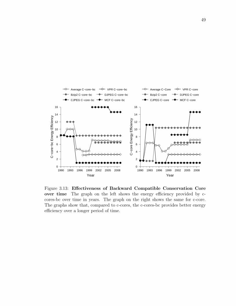
49
Year
1990 1993 1996 1999 2002 2005 2008
C−
core
Ene
rgy
Effi
cien
cy
0
2
4
6
8
10
12
14
16
Average C−Core VPR C−core
Bzip2 C−core DJPEG C−core
CJPEG C−core MCF C−core
Year
1990 1993 1996 1999 2002 2005 2008
C−
core
−bc
Ene
rgy
Effi
cien
cy
0
2
4
6
8
10
12
14
16
Average C−core−bc VPR C−core−bc
Bzip2 C−core−bc DJPEG C−core−bc
CJPEG C−core−bc MCF C−core−bc
Figure 3.13: Effectiveness of Backward Compatible Conservation Coreover time The graph on the left shows the energy efficiency provided by c-cores-bc over time in years. The graph on the right shows the same for c-core.The graphs show that, compared to c-cores, the c-cores-bc provides better energyefficiency over a longer period of time.
50
be significantly improved by designing compound circuits that can adapt to the
control flow of different application versions at runtime. The results also show that
this additional configurability comes at little expense to the energy efficiency of
the c-cores. These results are in keeping with the working assumption of this work,
which is that the key functions in mature applications do not change significantly
across versions, and hence, it is possible and desirable to provide reconfigurability
mechanisms in application-specific circuits, thus enabling these circuits to have
lifetimes comparable to those of general-purpose processors.
3.8 Conclusion
This chapter proposes patchable conservation cores, energy-efficient circuits
with targeted reconfigurability so that these circuits remain useful across applica-
tion versions. The main contribution of this work is the patching mechanism that
enables the newer application releases to be mapped onto the patchable c-core with-
out any source code modifications. The patching mechanism can provide enough
flexibility to ensure that c-cores will remain useful for up to 15 years, far beyond
the lifetime of most processors. This work also analyzes the area and energy over-
heads of these patching mechanisms and proposes optimizations to reduce them
without significantly affecting the c-core’s longevity. Also, this work proposes tech-
niques to improve the backward compatibility of the c-cores, allowing them to run
the legacy versions as efficiently as the latest version. Specialization has emerged
as an effective approach to scale system performance in spite of the utilization
wall phenomenon. However, lack of flexibility in application-specific circuits limits
the scope of the applications that they can target. To address this applicability
issue, this thesis proposes patching mechanisms that provide application-specific
circuits with increased flexibility, making them a suitable candidate for targeting
the mature applications in a system’s workload.

51
Acknowledgments
Portions of this research were funded by the US National Science Founda-
tion under NSF CAREER Awards 06483880 and 0846152, and under NSF CCF
Award 0811794.
This chapter contains material from “Conservation cores: reducing the
energy of mature computations”, by Ganesh Venkatesh, Jack Sampson, Nathan
Goulding, Saturnino Garcia, Vladyslav Bryksin, Jose Lugo-Martinez, Steven Swan-
son and Michael Bedford Taylor, which appears in ASPLOS ’10: Proceedings of the
fifteenth edition of ASPLOS on Architectural support for programming languages
and operating systems. The dissertation author was the primary investigator and
author of this paper. The material in this chapter is copyright c©2010 by the Asso-
ciation for Computing Machinery, Inc. (ACM). Permission to make digital or hard
copies of part or all of this work for personal or classroom use is granted without
fee provided that the copies are not made or distributed for profit or commercial
advantage and that copies bear this notice and the full citation on the first page in
print or the first screen in digital media. Copyrights for components of this work
owned by others than ACM must be honored. Abstracting with credit is permit-
ted. To copy otherwise, to republish, to post on servers, or to redistribute to lists,
requires prior specific permission and/or a fee. Request permissions from Publica-
tions Dept., ACM, Inc., fax +1 (212) 869-0481, or email [email protected].
This chapter contains material from “Efficient complex operators for irreg-
ular code”, by Jack Sampson, Ganesh Venkatesh, Nathan Goulding, Saturnino
Garcia, Steven Swanson and Michael Bedford Taylor, which appears in HPCA
’11: Proceedings of the International Symposium on High-Performance Computer
Architecture (HPCA). The dissertation author was the secondary investigator and
author of this paper. The material in this chapter is copyright c©2011 by the
Institute of Electrical and Electronics Engineers (IEEE). Personal use of this ma-
terial is permitted. Permission from IEEE must be obtained for all other uses,
in any current or future media, including reprinting/republishing this material for
advertising or promotional purposes, creating new collective works, for resale or
redistribution to servers or lists, or reuse of any copyrighted component of this

52
work in other works.

Chapter 4
Utilizing Conservation Cores to
Design Mobile Application
Processors
The market for smartphones and other portable devices continues to grow
rapidly. These mobile devices provide a rich user experience, enabling people to
stay connected, stream multimedia, play video games, and navigate using GPS-
powered maps. Moreover, this trend of mobile devices providing greater function-
ality and supporting a more diverse application set is only expected to continue
with the emergence of a new generation of mobile devices such as those based on
Apple iOS [App] and Google Android [Gooc]. However, these increasingly diverse
mobile applications strain the traditional model of manually designing specialized
hardware to address the power concerns and achieve better performance. In order
to provide this increasing functionality, new generations of mobile devices rely on
general-purpose processors, called the application processors.
At the same time, as explained in Chapter 1, the utilization wall phe-
nomenon is limiting the fraction of a chip that can be active simultaneously at full
frequency. While the utilization wall phenomenon is applicable across all compu-
tational domains, it is especially limiting for mobile devices because of restricted
power budgets. This threatens to limit the performance scaling of application
processors, impeding the evolution of what is becoming the dominant computing
53

54
platform for much of the world.
This work explores the potential for designing energy-efficient mobile ap-
plication processors by utilizing patchable conservation cores, explained in the
previous chapter. In particular, the work primarily focuses on designing energy-
efficient application processors for the Android-based mobile devices. The main
contribution of this work is to analyze the software stack of Android and use this
analysis to design conservation cores that can cover significant fraction of the An-
droid execution while staying within modest area budgets. This work demonstrates
that majority of the Android application execution time is spent in the Android
libraries and the Dalvik virtual machine [Goob], and leverages this fact to design
c-cores that can improve the energy efficiency and performance across a wide range
of current Android applications and potentially, future applications as well.
This chapter is organized as follows. Section 4.1 explains the applicability
of our c-core-based approach to the Android system. Section 4.2 presents the
Android’s internal architecture. Section 4.3 explains our approach for designing c-
cores targeting the hot code segments in the Android system. Section 4.4 examines
the area requirements of the c-cores that our approach designs and the energy
savings that these c-cores provide. Section 4.5 concludes this chapter.
4.1 Applicability of Conservation Cores to An-
droid
This work proposes an energy-efficient application processor for Android-
based mobile devices. This section first gives some background information about
the Android platform and then uses this analysis to demonstrate that c-cores are
a good fit for the Android system.
4.1.1 Android Platform Analysis
The Android software stack is shown in Figure 4.1. The core of the Android
platform comprises a collection of native libraries written in C and C++ that imple-

55
Figure 4.1: Android Software Stack The various layers of the Android’s internalarchitecture [Gooc].
ment most of the widely used services such as compression, window compositing,
2-D and 3-D graphics, and HTML rendering. This software stack layer also con-
tains the Dalvik virtual machine (DVM). The Dalvik virtual machine executes the
user application code, compiled down to the byte code, and provides access to the
native libraries via Java Native Interface calls.
Android architecture seeks to concentrate the performance-critical “hot”
code in the native libraries, which the Android applications can utilize to imple-
ment their key functionality. The remainder of the application code, much of which
will be relatively “cold,” runs on the Dalvik virtual machine, making the DVM
code “hot” as well. In this manner, most of the “hot” code that runs on the appli-
cation processor belongs to the Android software stack. The next section discusses
how this “library-centric” design of Android is a good match for the c-core-based
approach proposed in this thesis.

56
4.1.2 Case for using c-cores to optimize mobile application
processors
Android’s internal architecture relies very heavily on a small number of
shared software components, and there is a core set of commonly used applica-
tions (such as the web browser, video, music, and email programs) that represent
common-case usage across a large number of users. Targeting these shared compo-
nents will enable the c-cores to significantly reduce the system’s energy consump-
tion. A c-core-based approach can exploit the Android’s internal architecture in
the following two ways. First, the c-cores can target key portions of the native
libraries and Dalvik in order to provide energy reduction across the general class
of applications that run on the phone. These are termed as broad-based c-cores. In
our studies, these broad-based c-cores can collectively cover an average of 72% of
the execution of a typical Android mobile phone workload. Second, the c-cores can
target specific applications that many Android users run. These targeted c-cores
can, depending on the silicon area dedicated to them, cover from 80% to 90% to
even 95% of the targeted workload. Although targeted c-cores may not achieve
energy savings for new Android application releases, the rapid replacement cycle
of smartphones suggests that it is reasonable to continually develop new c-cores
for inclusion in future Android application processors as new applications achieve
popularity.
The above discussion demonstrates that the c-cores can cover a significant
fraction of the code execution on an application processor in Android-based mobile
devices. Also, as more area becomes available for specialization with each technol-
ogy generation, the c-core-based application processors can execute the Android
system more efficiently and incorporate hardware support for an ever increasing
number of desired functionalities.
4.2 Android Software Stack
This section describes the Android software platform including the Android
applications, application framework, shared libraries, and the Android runtime.

57
Android applications Android applications are written in Java. The appli-
cation code has access to the application framework APIs that they can use to
design their application user interface, access system resources such as the notifi-
cation bar, as well as access data from other applications. This application model
facilitates the reuse of components across applications.
Android shared libraries Android shared libraries implement most of the
widely used services such as system C library, window composting, and graph-
ics libraries. These Android libraries consist of many of the performance-critical
functions, are highly optimized for execution on mobile devices and are accessible
to the application code via application framework APIs. These shared libraries
enable the application code, written in Java, to implement much of their function-
ality in native C code. By design, these shared libraries would implement much of
the “hot” code that executes in the Android system.
Dalvik virtual machine The Dalvik virtual machine (DVM) executes the ap-
plication code that is compiled down to the Dalvik executable format. The Dalvik
virtual machine is optimized for running on a slow CPU with low main memory
without draining too much of the battery power. However, given that it is a virtual
machine executing the application code, executing a computation on the Dalvik
virtual machine is not as energy-efficient as executing the computation directly
on the CPU. Hence, given that all the application code written in Java executes
on the Dalvik virtual machine, ensuring that the execution of virtual machine is
energy-efficient is very critical as well.
The above discussion explains the high level design of the Android software
stack and shows that as a result of this design, the shared libraries and the Android
runtime account for much of the code that executes on the application processor.
The next section profiles the Android system and provides further details about
the hot code segments in the Android system.

58
4.3 Designing Conservation Cores for Android
The main goal of this section is to motivate the effectiveness of automat-
ically generated application-specific circuits in optimizing the energy efficiency of
application processors. Traditionally, mobile devices use hardware accelerators
that were manually designed for very specific computations such as graphics op-
erations. However, as the software stack of mobile devices becomes increasingly
general-purpose, the fraction of the code that executes on the application proces-
sor increases considerably. This section demonstrates that a large of fraction of
this general-purpose code can be supported in hardware within very modest area
budgets.
This section profiles the Android system executing many of the commonly
used Android applications. Next, this profile is used to characterize the hot code
segments in the Android system. Finally, based on this hot code analysis, this
section presents our approach for designing the c-core-based mobile application
processors.
4.3.1 Profiling the Android System
This section explains the profiler tool for profiling the execution of the
Android system. The profiler traces every instruction that executes on the CPU
including the kernel code. The next section post processes this instruction trace
to collect information about the hot code segments.
Android emulator The profiling step uses a QEMU-based Android emula-
tor [Gooa] to run the complete Android system including the Android shared
libraries, the Dalvik virtual machine and the Linux kernel.
The tracing records every instruction from every process that runs on the
CPU. This includes all the code in the native libraries, Dalvik virtual machine as
well as the linux kernel. This enables the analysis of the complete Android system
so that the hot code segments can be accurately determined. The tracing also
provides information about the memory system including the memory operations

59
executed and the cache hit/miss statistics. Moreover, this tracing does not need
any modifications to the application and occurs completely inside the emulator.
This enables the easy addition of more applications, as they become popular, to
our workload.
Android workload The profiling is done on a workload consisting of com-
monly used Android applications in order to profile typical smartphone execu-
tion. The workload comprises a diverse set of user-level applications including the
Web Browser, Google Mail, Google Maps, Google Music, Google Video, Pandora,
Photoshop Mobile, and RoboDefense.
4.3.2 Characterizing the hotspots in the Android system
This section analyzes the hot code segments in the Android system that
were found using the profiling methodology described in the previous section. The
analysis first examines the amount of static code that the hardware would need to
support in order to cover a significant fraction of the application execution. Then,
the analysis looks into how to provide this hardware support in a scalable manner
such that these specialized processors can provide energy improvements for a wide
range of commonly used applications.
Application Coverage
The fraction of the application execution spent on a c-core, or coverage,
is one of the key factors in determining how much benefit c-cores can provide.
For c-cores to achieve high coverage in a reasonable amount of area, a relatively
small fraction of the application’s instructions must account for a large fraction of
the dynamically executed instructions as well as that of the application execution
time. Figure 4.2 plots the fraction of the dynamically executed ARM instructions
(y-axis) covered by the number of static ARM instructions (x-axis) for our Android
application workload. In the figure, the top graph shows the average data across
all the applications, while the graphs below plot it for each of the applications. The
data shows that a relatively small number of static instructions account for a very

60
Average
Static Instruction Count0 2000 4000 6000 8000 10000 12000 14000
Dyn
. Ins
t.
00.20.40.60.8
1
0 4000 8000 12000 16000
Dyn
. Ins
t.
00.20.40.60.8
1
Photoshop
0 4000 8000 12000 16000
00.20.40.60.8
1
Browser
0 4000 8000 12000
Dyn
. Ins
t.
00.20.40.60.8
1
0 4000 8000 12000 16000
00.20.40.60.8
1
Gallery
0 4000 8000 12000 16000
Dyn
. Ins
t.
00.20.40.60.8
1
Maps
0 5000 10000 15000 20000
00.20.40.60.8
1
Video
Static Instruction Count0 4000 8000 12000 16000
Dyn
. Ins
t.
00.20.40.60.8
1
Pandora
Static Instruction Count0 4000 8000 12000
00.20.40.60.8
1
RoboDefense
Figure 4.2: Static Instruction Count vs Dynamic Instruction Count Cov-erage The graphs plot the dynamic instruction count coverage against the num-ber of static instructions required to get that coverage. The results show that asmall number of static instructions account for a large fraction of the dynamicinstructions that execute on the CPU. The top graph plots the results averagedacross all the applications, while the graphs below show the results for the An-droid applications - PhotoShop, Browser, Email, Gallery, Maps, Video, Pandora,and RoboDefense in that order.

61
Average
Basic Block Count0 2000 4000 6000 8000 10000
Cov
erag
e
00.20.40.60.8
1
0 2000 4000 6000 8000 10000
Cov
erag
e
00.20.40.60.8
1
Photoshop
0 2000 4000 6000 8000 10000
00.20.40.60.8
1
Browser
0 2000 4000 6000 8000 10000
Cov
erag
e
00.20.40.60.8
1
0 2000 4000 6000 8000 10000
00.20.40.60.8
1
Gallery
0 2000 4000 6000 8000 10000
Cov
erag
e
00.20.40.60.8
1
Maps
0 2000 4000 6000 8000 10000
00.20.40.60.8
1
Video
Basic Block Count0 2000 4000 6000 8000 10000
Cov
erag
e
00.20.40.60.8
1
Pandora
Basic Block Count0 2000 4000 6000 8000 10000
00.20.40.60.8
1
RoboDefense
Figure 4.3: Basic block count vs Application execution coverage The graphsplot the application execution coverage against the number of basic blocks requiredto get that coverage. The results show that a small number of basic blocks accountfor a large fraction of the application execution time. The top graph plots theresults averaged across all the applications, while the graphs below show the resultsfor the Android applications - PhotoShop, Browser, Email, Gallery, Maps, Video,Pandora, and RoboDefense in that order.

62
Pho
tosh
op
Em
ail
Pan
dora
Vid
eo
Bro
wse
r
Map
s
Rob
oDef
ense
Gal
lery
Run
time
0
0.2
0.4
0.6
0.8
1
.text / .data / heap Non−prelinked Libraries
Prelinked App Libraries Prelinked System Libraries
Linker Kernel
Figure 4.4: Breakdown of Application Runtime across Android SoftwareStack The graph plots the breakdown of application runtime across different layersof the Android software stack. The graph shows that majority of the applicationruntime is spent in the shared libraries.
large fraction of the dynamically executed instructions. On an average, supporting
2000 static instructions was enough to cover 80% of the dynamic instructions.
Figure 4.3 plots the application execution coverage (y-axis) versus the num-
ber of basic blocks required (x-axis) for our Android application workload. This
graph focusses on the fraction of total application execution time that the c-cores
can support. The graph shows that the c-cores can cover a significant fraction of
the application execution by supporting a relatively small number of basic blocks.
In particular, the c-cores can cover 90% of application execution on an average by
supporting 2000 basic blocks in the hardware, and this execution coverage can be
as high as 98% for certain applications.

63
Code Reuse Across Applications
The above analysis shows that the c-cores can cover a significant fraction of
an application execution by supporting a relatively small number of basic blocks.
In order to provide good end user experience, the c-cores should be able to cover
significant execution fraction across a wide range of commonly used applications.
However, providing specialization specific to each application can limit the number
of features that can be supported in hardware. The analysis below addresses this
scalability issue by demonstrating that a majority of the application execution
time is spent in the Android shared libraries, not in the application code itself.
Moreover, the analysis shows that, across our workload set, there is significant
code reuse across the code that executes for each application. This suggests that
supporting a small fraction of the shared library in the hardware can provide
benefits for a large number of applications.
Figure 4.4 presents the breakdown of the application execution time across
the application native code (shown as .text), the different shared libraries in the
Android system (shown as Non-prelinked Libraries, Prelinked App Libraries, Pre-
linked System Libraries), the linker, and finally the linux kernel (shown as Kernel).
The graph shows that the majority of the application execution time is spent in
the shared libraries. The applications on an average spend 78% of the execution
time in the shared libraries. This implies that the c-cores targeting these shared li-
braries can potentially optimize the execution of many applications and also, these
c-cores would be easily accessible to the newer applications that use these libraries.
The next experiment quantifies the code reuse across our application set
and proposes an approach for exploiting this code reuse to maximize the benefits
that the c-cores provide. To measure the code reuse, the analysis identifies identical
basic blocks across the execution traces of different applications. The results show
that, across our applications, 72% of the dynamic execution occurs in the code that
is shared across more than one application. Such a high level of code reuse drives
down the amount of static code that the c-cores need to cover in order to achieve
good overall coverage of dynamic execution. The next section discusses how the
code reuse data is incorporated into the algorithm for selecting the code segments

64
that when converted into c-cores provide the maximum execution coverage.
Conservation core Identification
This section presents the algorithm for selecting the code segments from the
Android system and the application code that should be converted into c-cores.
The main goal of this algorithm is to maximize the energy efficiency of the mobile
application processor while minimizing the area requirement of the c-cores. The al-
gorithm approximates the energy efficiency as the coverage that the c-cores provide
and approximates the c-core’s area requirement as the number of static instructions
supported by them. This energy approximation holds because, as shown in the
previous chapter, the c-cores are significantly more energy-efficient than general-
purpose processors, and offloading execution on to the c-cores improves the mobile
application processor’s energy efficiency. The area approximation is less precise be-
cause the area requirements of different instructions might vary. However, this first
order approximation allows the algorithm to explore a wide range of energy-area
tradeoff scenarios for designing the mobile application processors. Also, a more
accurate area approximation model is proposed in the next section that addresses
the inaccuracies.
The algorithm accepts as input the profile information of the Android work-
load set. For each application in the workload set, the algorithm processes the pro-
file information to find the hot basic blocks that account for much of the execution.
At this point, for each application, the algorithm has a breakdown of the time it
spends in various basic blocks. The next step involves determining the code reuse
across applications and using that to quantify each basic block’s global coverage,
the coverage that the basic block provides for the Android system as a whole. The
algorithm calculates the global coverage of each basic block as an arithmetic mean
of the coverage that the basic block provides across all the applications. Since the
global coverage metric is the coverage that the basic block provides for the Android
system, the algorithm can use this metric to compare the relative importance of
each basic block. The algorithm defines the quality metric of each basic block b as
globalCoverageb/areab, where globalCoverageb is the global coverage of the basic

65
block and areab is its area requirement. The algorithm sorts all the basic block in
descending order of their quality metric and tags the basic blocks for conversion to
c-cores until the target coverage is achieved or the area budget runs out. In this
manner, the c-core-identification algorithm explores the energy-area tradeoff space
and selects a number of pareto optimal design points.
Next, this section analyzes how effective the code regions selected by the
c-core identification algorithm are at covering significant portions of the Android
system execution while staying within modest area budgets. Figure 4.5 shows a
cumulative distribution of the percentage of dynamic coverage vs. the number of
static instructions converted into c-cores. In the figure, the top graph plots the
coverage that c-cores provide for the Android system. The dark-gray curve repre-
sents coverage for the broad-based c-cores, and the light-gray curve above it shows
the coverage for the targeted c-cores. The results show that the c-cores can support
90% of the system execution across our workload by implementing approximately
20000 static instructions. The majority of the execution coverage that the c-cores
provide belongs to the broad-based c-cores (64% coverage) implying that the ma-
jority of these c-cores would be useful across many of the existing applications and
even future applications that utilize the shared components. Moreover, as the area
available for specialization increases, the coverage that the c-cores provide can be
as high as 95%.
In Figure 4.5, the bottom eight graphs show the coverage that the c-cores
provide for each of the individual applications. The data shows that the c-cores
provide significant execution coverage across all these applications. The c-cores can
support at least 80% of the execution for each application if they support 20,000
static instructions. This implies that the broad-based c-cores and targeted c-cores
designed above are effective at supporting significant fraction of the execution
across all the applications in our workload.
The above analysis shows that small amount of static code accounts for
a large fraction of execution across many applications. By supporting these hot
code segments in hardware, the c-cores can optimize the execution of many of the
commonly used Android applications. The analysis also shows that the majority

66
Android System
Static Instruction Count0 10000 20000 30000 40000 50000 60000
Cov
erag
e
00.20.40.60.8
1
Targeted C−core Coverage
Broad−based C−core Coverage
0 10000 20000 30000 40000 50000 60000
Cov
erag
e
00.20.40.60.8
1
Browser
0 10000 20000 30000 40000 50000 60000
00.20.40.60.8
1
0 10000 20000 30000 40000 50000 60000
Cov
erag
e
00.20.40.60.8
1
Gallery
0 10000 20000 30000 40000 50000 60000
00.20.40.60.8
1
Maps
0 10000 20000 30000 40000 50000 60000
Cov
erag
e
00.20.40.60.8
1
Video
0 10000 20000 30000 40000 50000 60000
00.20.40.60.8
1
Pandora
Static Instruction Count0 10000 20000 30000 40000 50000 60000
Cov
erag
e
00.20.40.60.8
1
Photoshop
Static Instruction Count0 10000 20000 30000 40000 50000 60000
00.20.40.60.8
1
RoboDefense
Figure 4.5: Android Execution Coverage vs Static Instructions Convertedinto Conservation cores The graph plots the Android execution coverage againstthe number of static instructions required to get that coverage. The results showsthat supporting a small number of static instructions in hardware can providecoverage for a large fraction of the Android execution. The top graph plots thecoverage provided by broad-based c-cores and targeted c-cores for the Androidsystem, while the graphs below shows the coverage that these c-cores provide foreach of the Android applications.

67
of these c-cores would target shared code segments that are used across many
of the existing applications and hence, can potentially provide benefits for future
applications as well. Moreover, with each generation, the c-cores would be able to
provide higher execution coverage, which enables the mobile application processors
to continuously improve their support for the Android system.
4.4 Results
The previous section analyzes the Android system execution and proposes
a methodology for designing c-cores targeting a significant fraction of the Android
execution. This section examines the amount of area that c-cores would need to
provide this coverage and the possible energy efficiency improvements they can
provide. Based on the results presented in [VSG+10], this section builds an ana-
lytical model to approximate the area requirements of the c-cores for these Android
hotspots. Also, this section analyzes how the average dynamic energy per instruc-
tion metric varies with the area available for specialization.
4.4.1 Area requirement
In order to estimate the area requirements of the c-cores, this section first
builds an area model based on the instruction mix and the area requirements of
the c-cores presented in Chapter 3. The designing of the area model was aided
by the fact that c-core’s design very closely resembles the structure of the code
it targets and has generalized datapath operators and constant values to support
the patching mechanisms. The resultant area model was able to estimate the
area within 10% of the actual area on average with a standard deviation of 14.7%.
Based on our area model, conservatively, 1 mm2 area can implement approximately
3000 static instructions. With more aggressive area optimization techniques such
as those presented in [SVG+11], c-cores can implement approximately 6000 static
instructions in 1 mm2. This chapter uses the conservative area model for all the
analysis presented below.
Figure 4.6 plots the c-core’s coverage of the Android execution as the area

68
Android System
Area (in mm^2)0 2 4 6 8 10 12 14 16
Cov
erag
e
00.20.40.60.8
1
Targeted C−core Coverage
Broad−based C−core Coverage
0 2 4 6 8 10 12 14 16
Cov
erag
e
00.20.40.60.8
1
Browser
0 2 4 6 8 10 12 14 16
00.20.40.60.8
1
0 2 4 6 8 10 12 14 16
Cov
erag
e
00.20.40.60.8
1
Gallery
0 2 4 6 8 10 12 14 16
00.20.40.60.8
1
Maps
0 2 4 6 8 10 12 14 16
Cov
erag
e
00.20.40.60.8
1
Video
0 2 4 6 8 10 12 14 16
00.20.40.60.8
1
Pandora
Area (mm^2)0 2 4 6 8 10 12 14 16
Cov
erag
e
00.20.40.60.8
1
Photoshop
Area (in mm^2)0 2 4 6 8 10 12 14 16
00.20.40.60.8
1
RoboDefense
Figure 4.6: Android Execution Coverage vs Conservation core Area Thegraph plots the Android execution coverage against the c-core’s area requirement.The results show that majority of the Android execution can be covered by c-cores within very most area budgets. The top graph plots the coverage providedby broad-based c-cores and targeted c-cores for the Android system, while thegraphs below show the coverage that these c-cores provide for each of the Androidapplications.

69
available for specialization increases. The graph shows that if 2.75 mm2 area is
allocated for c-cores, they can cover 80% of the execution across all the applica-
tions. To put this area requirement in perspective, the die size of the NVIDIA’s
latest mobile application processor, called Tegra 2 [Ana], is 49 mm2. Hence, allo-
cating a little less than 6% of this mobile application processor for c-cores would
enable them to provide hardware support for the majority of the Android execu-
tion. Moreover, the graph shows that allocating 2.75 mm2 area for c-cores would
support majority of the execution ( greater than 70%) for all the applications in
the workload set, implying that this c-core-based approach for designing mobile
application processors can be effective across a wide range of Android applications.
4.4.2 Energy-Area Tradeoff
The above analysis explains how the area available for the c-cores effects
the fraction of the Android execution that executes on them. In this section, the
analysis focusses on the improvements in the energy efficiency that the c-cores
provide.
To estimate the energy savings, this work uses the energy model that
the work in [GSV+10] proposes. According to their model, considering dynamic
power, on an average the c-cores consume 8 pJ/instruction compared to the 91
pJ/instruction for the baseline MIPS processor, an improvement of 11×. These
values include data cache access energy which is shared between the c-cores and
the MIPS processor; for non-D-cache operations, c-cores reduce dynamic energy by
over 34×. This large gap in the execution efficiency demonstrates the importance
of achieving high c-core coverage; any code running on the MIPS processor is 11×more expensive.
Figure 4.7 shows the average dynamic energy per instruction vs. area ded-
icated to the c-cores. The graph shows that with mere 2.75 mm2 for c-cores,
the dynamic energy requirement for the Android system goes down by 73% over
an already power-efficient MIPS processor. Also, these c-cores reduce the energy
requirements for all the applications in the workload, with the benefits ranging
between 63% − 83%. Furthermore, if the area budget is increased to around 6
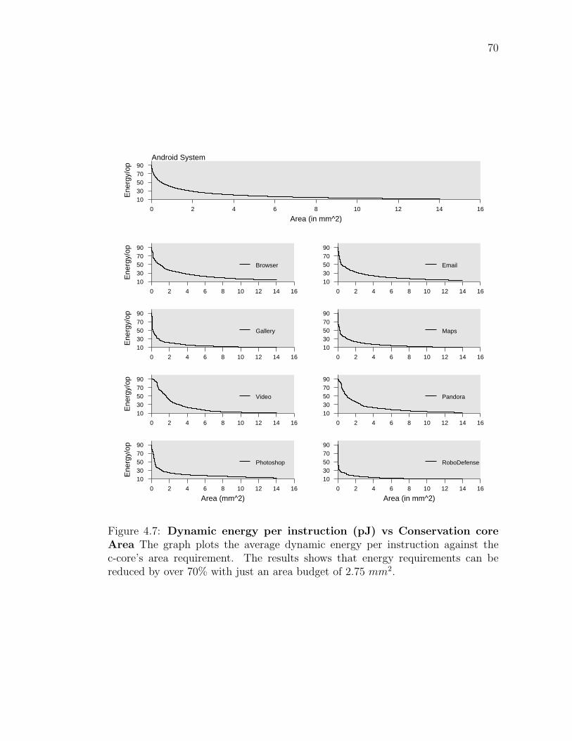
70
Android System
Area (in mm^2)0 2 4 6 8 10 12 14 16
Ene
rgy/
op
1030507090
0 2 4 6 8 10 12 14 16
Ene
rgy/
op
1030507090
Browser
0 2 4 6 8 10 12 14 16
1030507090
0 2 4 6 8 10 12 14 16
Ene
rgy/
op
1030507090
Gallery
0 2 4 6 8 10 12 14 16
1030507090
Maps
0 2 4 6 8 10 12 14 16
Ene
rgy/
op
1030507090
Video
0 2 4 6 8 10 12 14 16
1030507090
Pandora
Area (mm^2)0 2 4 6 8 10 12 14 16
Ene
rgy/
op
1030507090
Photoshop
Area (in mm^2)0 2 4 6 8 10 12 14 16
1030507090
RoboDefense
Figure 4.7: Dynamic energy per instruction (pJ) vs Conservation coreArea The graph plots the average dynamic energy per instruction against thec-core’s area requirement. The results shows that energy requirements can bereduced by over 70% with just an area budget of 2.75 mm2.

71
mm2, then the dynamic energy savings increase to 5.5× and this trend continues
as the area budget increases.
This section has shown that our c-core-based approach provides significant
energy savings and scalable amounts of specialization within a tight area budget,
in an automated fashion. Thus, our approach for designing mobile application
processors is an ideal fit for the Android system.
4.5 Conclusion
This chapter proposes a c-core-based approach for designing mobile ap-
plication processors, where the application processor comprises of c-cores target-
ing hotspots across a wide range of common mobile applications. This approach
enables increased specialization with each generation of mobile devices without
requiring any software application re-implementations. The results show that
a mobile application processor system consisting of a selection of targeted and
broad-based c-cores can reduce the processor energy consumption of a rich An-
droid workload by 73% and these improvements continue to increase as the area
budget available for c-cores increases.
The traditional approach of manually designing specialized hardware com-
ponents and optimizing mobile applications for the hardware system design is no
longer scalable. The approach presented in this chapter enables the mobile devices
to become increasingly powerful and run a more diverse set of applications with
each technology generation.
Acknowledgments
This chapter contains material from “The GreenDroid mobile application
processor: An architecture for silicons dark future”, by Nathan Goulding, Jack
Sampson, Ganesh Venkatesh, Saturnino Garcia, Joe Aurricchio, Po-Chao Huang,
Manish Arora, Siddharth Nath, Vikram Bhatt, Jonathan Babb, Steven Swanson
and Michael Bedford Taylor, which appears in IEEE Micro, March 2011. The

72
dissertation author was a significant contributor and author of this paper. The
material in this chapter is copyright c©2011 by the Institute of Electrical and Elec-
tronics Engineers (IEEE). Personal use of this material is permitted. Permission
from IEEE must be obtained for all other uses, in any current or future media,
including reprinting/republishing this material for advertising or promotional pur-
poses, creating new collective works, for resale or redistribution to servers or lists,
or reuse of any copyrighted component of this work in other works.

Chapter 5
Quasi-ASICs: Trading Area for
Energy by Exploiting Similarity
across Irregular Codes
Chapter 1 explained the technological trends behind the current utilization
wall phenomenon, and used it to motivate specialization as an effective solution
to achieve Moore’s law style performance scaling. Chapter 1 also presented the
two critical challenges — lack of flexibility, and lack of generality — that system
designers need to address in order to ensure that specialized cores can effectively
target a wide range of commonly used general-purpose programs. Chapter 3 pre-
sented our approach for addressing the first challenge, namely the lack of flexibility
in application-specific circuits. This rigidity of application-specific circuits limits
how long they remain useful because these circuits cannot support any change
in the source code they target, but most of the commonly used general-purpose
programs are routinely updated with newer versions containing new features, ad-
ditional optimizations or essential bug fixes. To make application-specific circuits
a suitable candidate for general-purpose programs, our approach proposed Patch-
able Conservation Cores (C-cores), energy-efficient co-processors that target a sin-
gle task and contain targeted reconfigurability to support changes in the target
program’s control-flow, datapath operators and memory layout. In this manner,
our approach allows the energy-efficient co-processors to remain useful for up to 15
73
74
years, and improve the application’s energy delay product by up to 20× compared
to a general-purpose processor.
This chapter addresses the second challenge that limits the wide applica-
bility of application-specific circuits, namely their lack of generality. The lack of
generality results in very narrowly defined specialized cores that can only target a
very specific task. This makes these specialized cores a poor candidate for provid-
ing hardware support for a significant fraction of execution of a varied application
set. From a system designer’s point of view, designing co-processors that can
support only one specific task can cause two main problems. Firstly, for many
applications in a system’s workload, it is not profitable to trade silicon for special-
ized co-processors that can only support that application. Secondly, supporting a
large number of tasks in hardware would necessitate designing a large number of
specialized cores, which in turn would make it difficult to place all of them close to
the general-purpose processor. This results in the increase of the overhead involved
in offloading a computation from a CPU to a specialized core, hence limiting the
benefits that these specialized cores can provide for short running computations.
To address the lack of generality challenge, this chapter proposes Quasi-
ASICs, specialized cores that unlike the traditional ASICs which target one specific
task, can support multiple general-purpose computations. These Qasics allow a
system designer to trade between area and energy efficiency in a fine-grained man-
ner. The Qasic design flow accomplishes this by varying the required number
of Qasics as well as their computational power based on the relative importance
of the applications and the area budget available to optimize these applications.
While the increase in Qasic’s computational power comes with marginal decrease
in their energy efficiency, these Qasics are still an order of magnitude more energy-
efficient than general-purpose processors. In this manner, our approach can signifi-
cantly reduce the number of specialized processors as well the area budget required
compared to that of fully-specialized logic, without compromising on the fraction
of system execution that the specialized logic supports.
Qasics achieve energy- and area-efficiency by leveraging code similarity
within and across applications. The Qasic tool chain mines for similar computa-

75
Decreasing Area Budget
1 0.95 0.9 0.85 0.8 0.75
Ene
rgy
Effi
cien
cy
1
3
5
7
9
11
Fully−Specialized LogicQASICs
Figure 5.1: Trade offs between area and energy efficiency The x-axis variesthe area budget available for specialization, normalized to the area budget requiredto implement all our application hotspots (Table 5.1) using fully-specialized logic.The y-axis measures energy consumption relative to an in-order MIPS processor.As area budgets decrease, Qasics energy efficiency declines much more slowly thanit does for fully-specialized logic, because Qasics can save area by increasing theQasic’s computational power rather than removing functionality.
tions across the system’s workload and designs a Qasic that can execute all these
computations. This allows Qasics to reduce area requirements without reducing
the fraction of the program that executes on specialized hardware.
Figure 5.1 demonstrates that compared to the Patchable Conservation Core
approach, Qasics give up very little efficiency in return for substantial area savings.
As the area budget decreases (left to right on the X-axis), the Qasic toolchain
designs Qasics with greater computational power to ensure that they continue to
support all the application hotspots in hardware. This increase in the generality
of Qasics enable them to provide significant energy efficiency even as the area
budget decreases, unlike c-cores that sees a 4× decrease in their energy efficiency.
This chapter addresses many of the challenges involved in designing a Qa-
sic-enabled system. The first challenge lies in identifying similar code patterns
across a wide range of general-purpose applications. The hotspots of a typical
general-purpose application tend to have many hundreds of instructions, com-

76
plex control-flow and irregular memory-access patterns, making the task of finding
similarity both algorithmically challenging and computationally intensive. The
second challenge lies in exploiting the similar code patterns to reduce hardware
redundancy by designing generalized code-structures that can execute these code
patterns. The third challenge involves making the area-energy tradeoffs to ensure
that these co-processors fit within the area budget. Addressing this challenge en-
tails finding efficient heuristics that approximate an exhaustive search of the design
space but avoid the exponential cost of that search. The final challenge involves
modifying the application code/binary appropriately to enable the applications to
offload computations on to the Qasics at runtime.
This chapter evaluates the proposed toolchain by designing Qasics for the
find, insert, delete operations of the commonly used data structures, namely
link-list, binary tree, AA tree, and hash table. The results show that designing
just four Qasics can support all these data structure operations and can pro-
vide 13.5× energy savings over a general-purpose processor. On a more diverse
general-purpose workload consisting of twelve applications selected from different
application domains (including SPECINT, Sat Solver, Vision, EEMBC, among
others), the results show that Qasics reduce the required number of application-
specific circuits by over 50% and the area requirement by 23% compared to the
fully-specialized logic while providing energy-efficiency within 1.27X of that of
fully-specialized logic.
The rest of this chapter is organized as follows. Section 5.1 motivates the
Qasic approach in the context of other proposals. Section 5.2, 5.3, and 5.4.2
describes the Qasic design and hardware generation flow. Section 5.5 evaluates
the Qasic approach. Section 5.6 concludes.
5.1 Motivation
To effectively utilize the available transistor budget, this chapter proposes
a design methodology that varies the Qasic’s computational power based on the
area budget available for specialization. The Qasic design methodology is based
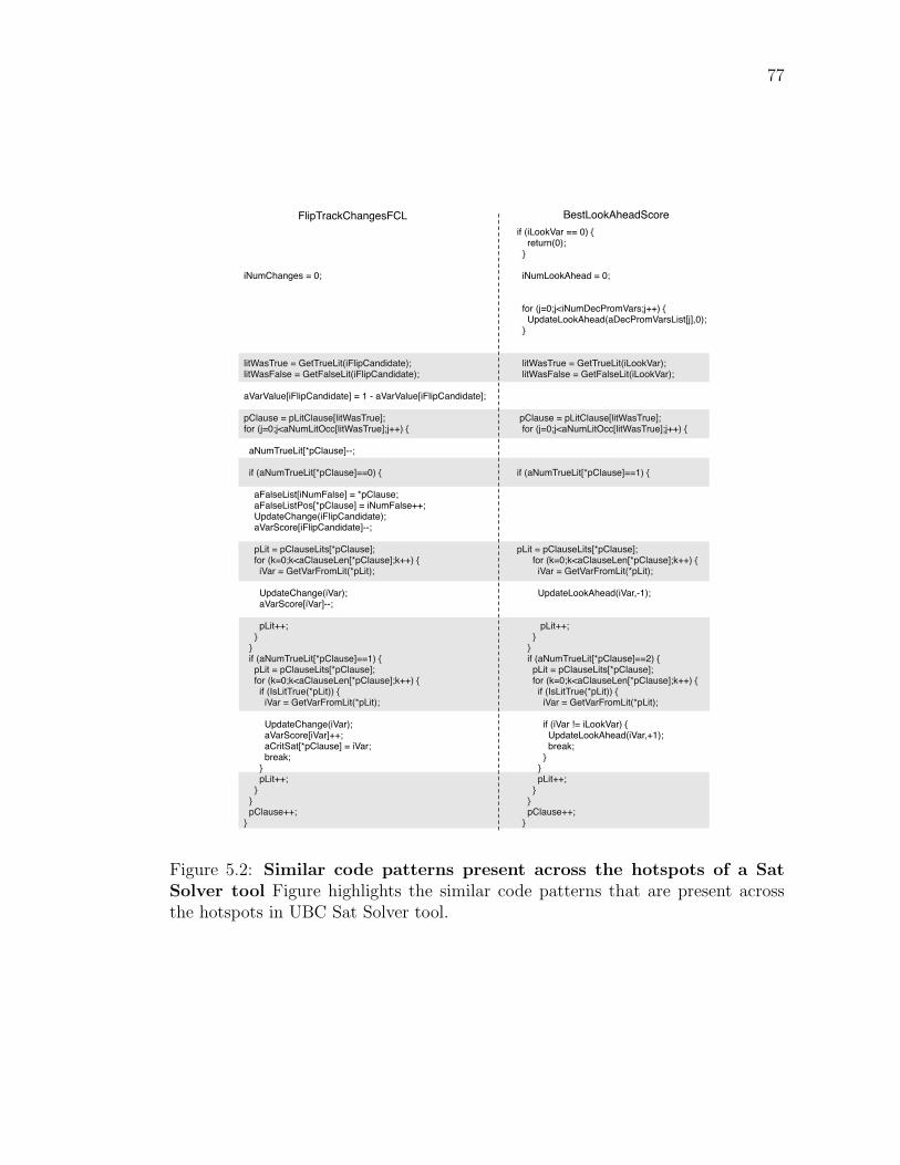
77
iNumChanges = 0;
litWasTrue = GetTrueLit(iFlipCandidate); litWasFalse = GetFalseLit(iFlipCandidate); aVarValue[iFlipCandidate] = 1 - aVarValue[iFlipCandidate]; pClause = pLitClause[litWasTrue]; for (j=0;j<aNumLitOcc[litWasTrue];j++) { aNumTrueLit[*pClause]--;
if (aNumTrueLit[*pClause]==0) { aFalseList[iNumFalse] = *pClause; aFalseListPos[*pClause] = iNumFalse++; UpdateChange(iFlipCandidate); aVarScore[iFlipCandidate]--; pLit = pClauseLits[*pClause]; for (k=0;k<aClauseLen[*pClause];k++) { iVar = GetVarFromLit(*pLit); UpdateChange(iVar); aVarScore[iVar]--; pLit++; } } if (aNumTrueLit[*pClause]==1) { pLit = pClauseLits[*pClause]; for (k=0;k<aClauseLen[*pClause];k++) { if (IsLitTrue(*pLit)) { iVar = GetVarFromLit(*pLit); UpdateChange(iVar); aVarScore[iVar]++; aCritSat[*pClause] = iVar; break; } pLit++; } } pClause++; }
if (iLookVar == 0) { return(0); }
iNumLookAhead = 0;
for (j=0;j<iNumDecPromVars;j++) { UpdateLookAhead(aDecPromVarsList[j],0); }
litWasTrue = GetTrueLit(iLookVar); litWasFalse = GetFalseLit(iLookVar);
pClause = pLitClause[litWasTrue]; for (j=0;j<aNumLitOcc[litWasTrue];j++) {
if (aNumTrueLit[*pClause]==1) {
pLit = pClauseLits[*pClause]; for (k=0;k<aClauseLen[*pClause];k++) { iVar = GetVarFromLit(*pLit);
UpdateLookAhead(iVar,-1);
pLit++; } } if (aNumTrueLit[*pClause]==2) { pLit = pClauseLits[*pClause]; for (k=0;k<aClauseLen[*pClause];k++) { if (IsLitTrue(*pLit)) { iVar = GetVarFromLit(*pLit); if (iVar != iLookVar) { UpdateLookAhead(iVar,+1); break; } } pLit++; } } pClause++; }
BestLookAheadScoreFlipTrackChangesFCL
Figure 5.2: Similar code patterns present across the hotspots of a SatSolver tool Figure highlights the similar code patterns that are present acrossthe hotspots in UBC Sat Solver tool.
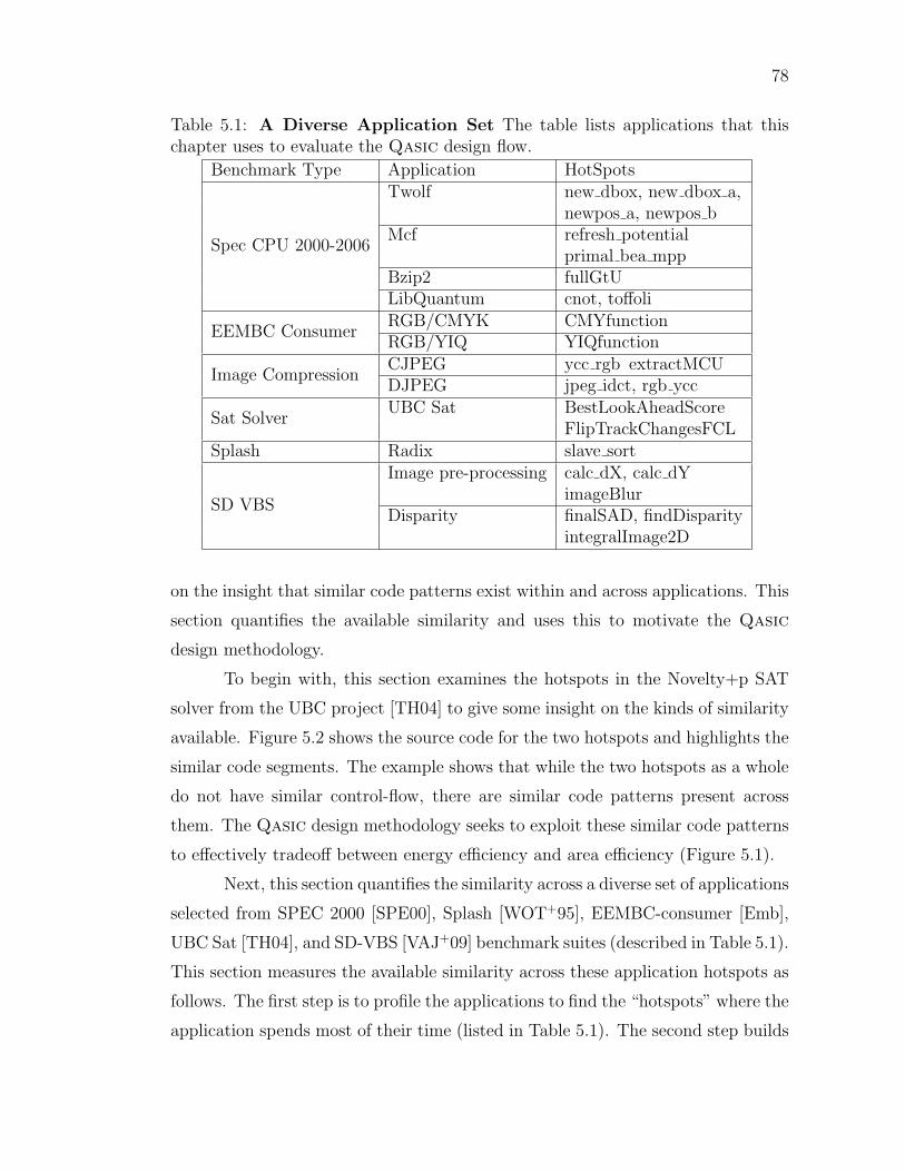
78
Table 5.1: A Diverse Application Set The table lists applications that thischapter uses to evaluate the Qasic design flow.
Benchmark Type Application HotSpots
Spec CPU 2000-2006
Twolf new dbox, new dbox a,newpos a, newpos b
Mcf refresh potentialprimal bea mpp
Bzip2 fullGtULibQuantum cnot, toffoli
EEMBC ConsumerRGB/CMYK CMYfunctionRGB/YIQ YIQfunction
Image CompressionCJPEG ycc rgb extractMCUDJPEG jpeg idct, rgb ycc
Sat SolverUBC Sat BestLookAheadScore
FlipTrackChangesFCLSplash Radix slave sort
SD VBS
Image pre-processing calc dX, calc dYimageBlur
Disparity finalSAD, findDisparityintegralImage2D
on the insight that similar code patterns exist within and across applications. This
section quantifies the available similarity and uses this to motivate the Qasic
design methodology.
To begin with, this section examines the hotspots in the Novelty+p SAT
solver from the UBC project [TH04] to give some insight on the kinds of similarity
available. Figure 5.2 shows the source code for the two hotspots and highlights the
similar code segments. The example shows that while the two hotspots as a whole
do not have similar control-flow, there are similar code patterns present across
them. The Qasic design methodology seeks to exploit these similar code patterns
to effectively tradeoff between energy efficiency and area efficiency (Figure 5.1).
Next, this section quantifies the similarity across a diverse set of applications
selected from SPEC 2000 [SPE00], Splash [WOT+95], EEMBC-consumer [Emb],
UBC Sat [TH04], and SD-VBS [VAJ+09] benchmark suites (described in Table 5.1).
This section measures the available similarity across these application hotspots as
follows. The first step is to profile the applications to find the “hotspots” where the
application spends most of their time (listed in Table 5.1). The second step builds

79
Percentage Node Match90 100 80 90 70 80 60 70 50 60 40 50
Perc
enta
ge H
otsp
ot P
airs
0
5
10
15
20
25
30
35
40
45
Figure 5.3: Similarity available across hotspots of diverse application set(Table 5.1)The X plots shows the amount of similarity present and Y axis showsthe percentage of pairs that have certain merge percentage shown on the X axis.
the Program Dependence Graphs (PDG) [FOW87] for these hotspot functions.
The final step finds the similar code segments across these hotspots by searching
for isomorphic subgraphs across their PDGs (Section 5.2.2 discusses the similarity
algorithm). The similarity between the hotspots is quantified as the fraction of
matching nodes between their PDGs.
The results, shown in Figures 5.3 & 5.4, demonstrate that significant sim-
ilarity exists within and across applications. Figure 5.3 bins the hotspot pairs
based on the amount of similarity present between them. The X axis shows the
similarity bins and the Y axis shows number of hotspot pairs present in the bins.
The data shows that most of the hotspot pairs (> 90%) had some similar code
patterns (50% node matched) and more importantly, at least 50% of the hotspot
pairs had significant similarity (> 80% nodes matched). Also, Figure 5.4 shows

80
!"
#!"
$!"
%!"
&!"
'!!"
'#!"()*+,-
./"
+012)34./"
+5.("
+530+6"
47+7)*
"
+012)34./"
+5.("
+530+6"
47+7)*
"
+5.("
+530+6"
47+7)*
"
+530+6"
47+7)*
"()*+,-./" +012)34./" +5.(" 47+7)*"
8./(.*
109.":);
."<01(6"
=5537(0>)*"2),/(."507/+"
Figure 5.4: Quantifying Similarity Present Within and Across Applica-tion Domains. The graph quantifies similarity present across different classes ofapplications.

81
that significant similarity exists within and across application domains as well.
To exploit the available similarity, the Qasic toolchain merges application
hotspots with similar code structure and builds one Qasic for them. This design
methodology provides the following benefits:
1. Fewer number of specialized circuits and reduced area require-
ments: This chapter realizes these reductions by designing Qasics that
can support multiple similar computations. The Qasic toolchain found
these similar computations across hotspots of the same application (such
as term_newpos_a and term_newpos_b from Twolf), across different appli-
cations in the same application domain (such as different image conversion
algorithms), and even across applications from different application domains
(such as Bzip2 and Disparity).
2. Generality: The Qasics tend to have more flexible control and data flow
compared to fully specialized hardware because they are designed to target
multiple code segments. As a result, Qasic’s computational power can ex-
tend beyond the code segments for which they were designed. For example,
in our benchmark set, the imageBlur kernel uses a 5-stage filter [VAJ+09]
and the edgeCharacteristics kernel uses a 3-stage filter. However, the Qa-
sic formed by merging imageBlur and edgeCharacteristics can execute both
the kernels with either image-filter, providing this Qasic with additional
computational power.
3. Better backward compatibility for application-specific hardware: In
order to remain useful across software versions, application-specific hardware
must be able to adapt to changes in the code it supports. The design method-
ology that this section proposes can be utilized to improve the application-
specific circuit’s support for the legacy “in-use” versions, as shown in Sec-
tion 3.7

82
Application HotSpots
Select Best QASIC Set
Merge Matched Expression
Similar Code Regions Present
Yes
No
Linearize Program Dependence Graphs
QASIC Specification Generation
Create Dependence Graphs
Merge Similar Components
Figure 5.5: Qasic Design Flow The design flow from application hotspots toQasic generation is shown.
5.2 Quasi-ASIC Design Flow
This section presents the details of the Qasic design flow (shown in Fig-
ure 5.5). The design flow accepts the target application set and the area budget
as input and generates as output a set of Qasics that fit within the available area
budget and can support a significant fraction of the execution of target applica-
tions.
The design flow starts with a set of dependence graph for each of the ap-
plication hotspots. At each stage, the toolchain selects the dependence graph pair
with similar code patterns, merges the dependence graph pair to build a new de-
pendence graph, and replaces the dependence graph pair with the new merged
graph. This process continues until the toolchain is unable to find similar code
segments across the dependence graphs or the area goals are met. These steps are
described in greater detail below.
Figure 5.6(a)-(d) shows the process of merging similar hotspots, compute-
Sum and computePower, to form a Qasic.

83
5.2.1 Dependence Graph Generation
The Qasic toolchain internally represents the application hotspots as Pro-
gram Dependence Graphs(PDG) [FOW87], where nodes represent statements and
edges represent control and data dependencies. The PDG representation of the
hotspots is better suited for finding matching code regions than control flow graphs
or program text because it enables the code pattern matching to be based on the
program semantics rather than the program code text. Using PDG, the toolchain
gets rid of all the false dependencies, preserving only the “real” control and data
dependences. Figure 5.6(a) shows the PDG for a simple loop that computes sum
of first n numbers. The solid edges represent control dependence and dashed ones
represent data dependence. Unlike a control flow graph, there is no edge between
the nodes sum = 0 and i = 0 because these statements are independent of each
other.
The Qasic design flow uses CodeSurfer tool [Cod] to create PDGs for the
input code segments. The output of this stage is a pool of PDGs of the application
hotspots. The subsequent steps of the design flow increase the generality of these
PDGs and reduce hardware redundancy in this PDG pool until the area budget is
met.
5.2.2 Mining for Similar Code Patterns
This step seeks to find dependence graph pairs from the Qasic PDG
pool that are similar to each other. The problem of finding similar code pat-
terns across application hotspots can be reduced to finding similar subgraphs
(subgraph-isomorphism) across their PDGs. The subgraph-isomorphism is a well
studied [Epp95, FK98, HWP03] problem in the field of graph algorithms. Our
algorithm for mining similar code patterns is based on the FFSM algorithm pro-
posed by Huan et al. [HWP03]. This section presents a brief description of the
FFSM algorithm and the optimizations that were made to tailor this algorithm to
the problem of finding similar code fragments.
The graph matching algorithm (FFSM) takes as input two graphs, G1, G2,
where every node in both the graphs have a unique ID as well as type label. The

84
algorithm considers two nodes for matching only if they have the same type label.
The algorithm begins by selecting a node n1 randomly in G1 and finds a matching
node n2 for n1 in G2. Then, it tries to grow the matched subgraph by comparing
the neighbors of n1 and n2 as well as performing other join operations on the
matched subgraphs (refer to [HWP03] for details). The algorithm returns when it
cannot grow the subgraph any further.
The Qasic toolchain extends the FFSM matching algorithm in several
ways to tailor it to the problem of finding similar code patterns in PDGs. First,
instead of picking and matching nodes in a random order, our matching algorithm
focuses on finding similar loop bodies. This behavior is desirable since most of
the application execution time is spent in loops. Secondly, the PDG node type
encodes the program structure so as to prune “illegal” matches and reduce the
search space. For example, all the nodes within a loop body should have “similar”
node type and different from the node type of any nested loop nodes within that
loop. This node type definition ensures that two nodes would match only if they
perform similar arithmetic operations (for example addition and branch operations
are not similar ), similar memory operations (such as array/pointer access), and
the control/data edges associated with these two nodes match.
For example, when trying to find similar code patterns across computeSum
and computePower, shown in Figure 5.6(a), this stage would map the sum+=i
node in computeSum to sum*=sum of computePower, among others. All the
node mappings that this stage produces are shown in Figure 5.6(b).
The output of this stage is a list of dependence graph pairs that have similar
code patterns present across them. For each of these similar dependence graph
pairs, this stage also produces a mapping of the similar code patterns across them.
5.2.3 Merging Program Dependence Graphs with similar
code structure
This stage of the Qasic design flow accepts as input the similar dependence
graph pairs that the previous stage produces. For each dependence graph pair, this
stage merges their mapped nodes to form a new Qasic dependence graph that is
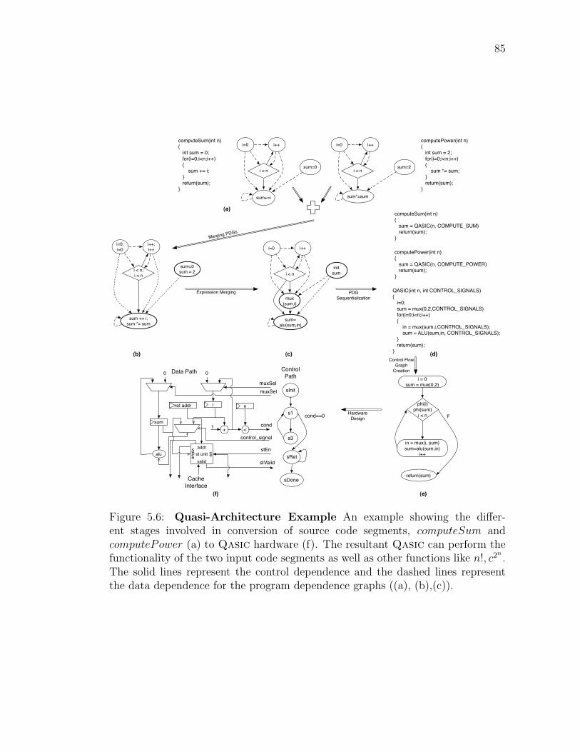
85
computeSum(int n){ int sum = 0; for(i=0;i<n;i++) { sum += i; } return(sum);}
i=0 i++
sum=0i < n
sum+=i
computePower(int n){ int sum = 2; for(i=0;i<n;i++) { sum *= sum; } return(sum);}
i=0 i++
sum=2i < n
sum*=sum
i=0 i++
init sumi < n
mux (sum,i)
sum= alu(sum,in)
i=0;i=0
i++;i++
sum=0sum = 2i < n;
i < n
sum += i;sum *= sum
Expression Merging PDG Sequentialization
computePower(int n){ sum = QASIC(n, COMPUTE_POWER) return(sum);}
computeSum(int n){ sum = QASIC(n, COMPUTE_SUM) return(sum);}
QASIC(int n, int CONTROL_SIGNALS){ i=0; sum = mux(0,2,CONTROL_SIGNALS) for(i=0;i<n;i++) { in = mux(sum,i,CONTROL_SIGNALS); sum = ALU(sum,in, CONTROL_SIGNALS); } return(sum);}
Merging PDGs
(a)
(b) (c) (d)
i = 0sum = mux(0,2)
phi(i)phi(sum)
i < n
in = mux(i, sum)sum=alu(sum,in)
i++
return(sum)
F
(e)
st unitaddr
valid
en
valuealu
0 0
+1
muxSelmuxSel
stEn
stValid
<
n
cond
Data Path
sInit
s1
s3
sDone
cond==0
Control Path
Cache Interface
sum
iret addr
sRet
(f)
Control Flow Graph
Creation
Hardware Design
control_signal
Figure 5.6: Quasi-Architecture Example An example showing the differ-ent stages involved in conversion of source code segments, computeSum andcomputePower (a) to Qasic hardware (f). The resultant Qasic can perform thefunctionality of the two input code segments as well as other functions like n!, c2
n.
The solid lines represent the control dependence and the dashed lines representthe data dependence for the program dependence graphs ((a), (b),(c)).

86
capable of supporting all the computations that either of its input dependence
graph can support.
The main challenge in this step is to ensure that the Qasic PDGs it pro-
duces are linearizable, in that there is a sequential ordering of the PDG nodes
that respects all the data and control dependences. To preserve this linearizable
property, the Qasic’s PDG must be reducible and have no circular data/control
dependence. A PDG is reducible if each of its loop body has a single entry point.
As the first step, this stage ensures that there are no circular dependence
in the merged PDG using control, data, and inferred (explained later) dependence
edges. This stage eliminate the circular dependences by removing the least number
of node matches that would break all the dependence cycles. The next step is to
merge the loop entry nodes and in the process, ensure that each loop body has
only one entry point. During this step, for each code region with multiple entry
points, the toolchain adds dummy control nodes as entry points to maintain a
reducible control dependence graph. Next, this stage builds a one-to-one map
between variables of the two PDGs based on the nodes that got matched. The
toolchain uses this variable map to match the declaration and phi nodes that were
ignored in the Section 5.2.2 to reduce subgraph matching time. At this point, this
stage merges the two PDGs to form a new PDG of the Qasic that can execute
computation corresponding to both the merging pdgs.
Figure 5.6(b) shows the PDG of the Qasic that our toolchain designs by
merging the dependence graphs of computeSum and computePower, shown in Fig-
ure 5.6(a).
The Qasic PDG contains additional node and edge attributes to enable
PDG linearization (Section 5.2.4).
1. Node Attributes: Each node in the PDG contains a list of variables defined
and used by that node. This node attribute is extended to contain a list of
conditionally defined and used variables. For example, in Figure 5.6(b) sum
+=i; sum∗=sum node conditionally consumes variable i because only one
of its input code segments (computeSum) consumes i.
2. Edge Attributes: The PDG is augmented with conditional data depen-

87
dences. The conditional edges result from edges present in only one of the
two PDGs being merged. For example, computeSum in Figure 5.6(b) has
data dependence between i++ and sum +=i but there is no data depen-
dence between i++ and sum∗=sum. This leads to a conditional dependence
from i++ to sum+=i; sum∗=sum in the Qasic’s PDG.
At this point, this stage has designed a Qasic PDG corresponding to each
similar dependence graph pair that the previous stage produced. Each of these
newly designed Qasics have greater computational power than the two depen-
dence graphs they were formed from because they can support the computations
that either of their input dependence graph can support. Moreover, these Qasics
requires lesser area compared to its input dependence graphs because they elimi-
nate hardware redundancy across the input dependence graphs by merging similar
computations.
The final step of this stage is to select the Qasic that, when compared to the
dependence graph pair they were formed from, will provide the maximum benefits
in terms of the area saved and increase in the computational power. Section 5.3
explains in detail our heuristic for performing this Qasic selection. Once the best
Qasic candidate is chosen, this stage replaces the two input PDGs with the chosen
Qasic’s PDG in the PDG pool.
At the end of this stage, the toolchain loops back to the second stage (Sec-
tion 5.2.2) to find other potential PDG pairs for merging. Eventually, the Qasic
set becomes distinct enough that no substantial similarity can be found across
them. At that point, the toolchain proceeds to generate the Qasic specifications
explained in the next section.
5.2.4 Qasic Generation
The fourth stage of the toolchain sequentializes the PDGs of the Qasic set
to produce the Qasic specification in C, which is used to generate Verilog code
by the backend of our toolchain. The two steps involved in this stage are merging
the matched expressions present in each Qasic PDG node and sequentializing the
Qasic’s data and control dependences.

88
=
sum
sum i
+
=
sum
sum sum
*
=
sum
sum
alu
mux
sum i
sum += i sum *= sum
sum = alu(sum, mux(sum,i,muxControl), aluControl)
Figure 5.7: Expression Merging An example showing merging of the expressiontrees of the two input expressions to build the new merged expression tree and thecorresponding expression.
while(i<n) A{ if(...) P { a = 5; b = a + 6; } if(...) Q { a = 5; c = a + 6; } if(...) R { d = a; e = b; }}
P Q
R
Data Dependence Graph
Figure 5.8: Inferred Dependence Example The solid and dashed lines showtrue and inferred dependences. There is an inferred dependence edge from P to Qbecause no valid ordering of P,Q,R orders Q before P (Section 5.2.4).

89
Merging Expressions This step generates a valid C-expression corresponding
to each node of a Qasic. The Qasic PDGs that the previous step designs consist
of multiple C-expressions in each of its nodes. For example, in Figure 5.6(b), a
Qasic PDG node contains the expressions sum += i (from computeSum PDG)
and sum *= sum (from computePower PDG). To design this merged C-expression,
this stage builds expression trees using ANTLR [Ter], which are then merged into a
single expression tree. This merged tree directly translates to a valid C-expression.
This process is shown in Figure 5.7. This step achieves much of the area reduction
seen in our results by reusing datapath operands and operators. For example,
in Figure 5.6(c), the Qasic eliminates hardware redundancy by merging i < n
expression used in both computeSum and computePower. Figure 5.6(c) shows
the result of merging expressions for the PDG shown in Figure 5.6(b).
Linearizing Qasic PDGs The PDGs are inherently parallel representation of a
program. However, in order to produce Qasic specification in C, this stage would
need a valid ordering of nodes consistent with the control and data dependence
edges. The ordering of control edges in a Qasic PDG is straightforward and
the previously proposed techniques for reducible graphs [FOW87] work in our
case as well. Sequentializing the data dependence is more challenging because
of the conditional data flow edges as well as conditionally defined-used variables
in the PDG nodes. This stage uses the following technique to sequentialize data
dependences including the conditional node and edge attributes of Qasic PDG
nodes.
The main goal of our technique is to order the nodes in the presence of
conditional data dependence without employing backtracking (computation time
for backtracking-based techniques can get very expensive, exponential in the worst
case, as the PDG’s size and complexity increases). Our technique uses the data
dependence edges and use/def analysis to build inferred dependences between chil-
dren of same control node. The inferred dependence is defined as follows: Let us
say that parent node A has child nodes P and Q. The child P has inferred de-
pendence on child Q if there exists a child R of parent node A such that child P
produces some value b that child R consumes, child Q produces some value a that

90
child R consumes, and child P also produces the value a. This implies that only
valid ordering among them is for child P to execute before child Q. An example of
this is shown in Figure 5.8. The subgraph P produces values a and b, subgraph Q
produces values a and c. There is no dependence between P and Q. The subgraph
R consumes value a from Q and b from P causing an implicit ordering between
P and Q. This stage uses the data dependence, inferred dependence and use/def
analysis to linearize the data dependence. To handle additional node and edge
attributes of the Qasic PDG, the data structures used in data dependence seri-
alization algorithm are extended with these attributes as well. Our linearization
algorithm, based on inferred dependence, lends itself to easily support conditional
data dependence and the algorithm’s computation time scales well w.r.t. the size
and complexity of the Qasic PDG.
The Qasic formed by merging computeSum and computePower is presented
in Figure 5.6(d). Based on the value of the CONTROL_SIGNALS, this Qasic can
be configured to support the computations performed by computeSum as well
as computePower. In addition, this Qasic can also be configured to perform
other operations such as factorial, c2n, besides computeSum and computePower
by configuring the control lines to the mux, ALU and init value of sum.
5.2.5 Modifying Application Code to utilize Qasics
The Qasic toolchain also modifies the application code to allow it to offload
the computations on to the Qasic at the runtime. The toolchain does this by
determining a valid setting of the Qasic’s CONTROL_SIGNAL input that would allow
the Qasic to execute the computation desired by the calling application. For
example, Figure 5.6(d) shows how the application code is modified to use the
Qasic. In this example, the computeSum function sends the function argument
values as well as an additional argument that would configure the ALU in the Qasic
to perform addition. Moreover, the toolchain also inserts stubs in the application
code to query the runtime for the availability of a matching Qasic(not shown
in the figure for simplicity). In case no matching Qasic is present or available
at runtime, then the application defaults to running the software version of the

91
function on the general-purpose processor.
5.3 Qasic-selection heuristic
The previous section describes the design methodology for merging appli-
cation hotspots and building the appropriate Qasic set for them. Section 5.2.3
described the methodology for merging two hotspots with similar code structures.
However, a hotspot can match well with multiple other hotspots. For exam-
ple, integralImage2D hotspot in Disparity matches well with multiple hot spots
(slave sort in Radix, findDisparity in Disparity) belonging to different application
classes and having different code sizes. In general, there are exponentially different
alternatives for merging the application hotspots to form the final Qasic set. This
section presents the Qasic-selection heuristic to decide which hotspots to merge
to make the best area-energy tradeoffs.
Our tool chain’s goal is to find the set of Qasics that will most significantly
reduce the power consumption while fitting within the available area budget. The
reduction in power consumption that a Qasic can deliver is a combination of its
power efficiency and fraction of programs that it executes. Formally, a Qasic b
occupies area Ab, consumes power Pb, has speedup Sb, and has coverage Cb (relative
application importance determined by system-level profiling).
To evaluate b, this section defines a quality metric Qb = CbSb
AbPb. To select a
good set of Qasics to build, the Qasic toolchain will need to compute Qb for an
enormous number of candidate Qasics. Computing precise values for Sb and Pb
in each case is not tractable since it requires full-fledged synthesis and simulation.
To avoid this overhead, this stage makes the following approximations.
First, this stage conservatively assumes that the speedup, Sb, is always 1. As
shown in Chapter 3, the specialized cores for integer programs are typically no more
than twice as fast as a general purpose processor. This stage estimates Ab based
on the datapath operators and register counts. Next, the Qasic-selection heuristic
assumes that power consumption is proportional to area. This approximation is
valid if we assume constant activity factors, constant clock frequencies, and circuit

92
tional attributes. Our linearization algorithm based on inferred de-pendence lends itself to easily support conditional data dependenceand the algorithm’s computation time scales well w.r.t. the size andcomplexity of the QASIC PDG.
The final linearized QASIC formed by merging computeSumand computePower is presented in Figure 6(d). Based on thevalue of the CONTROL_SIGNALS, this QASIC can be configuredto support the computations performed by computeSum as wellas computePower. In addition, this QASIC can also be config-ured to perform other operations such as factorial, c2n
, besidescomputeSum and computePower by configuring the controllines to the mux, ALU and init value of sum.
3.5 Modifying Application Code to utilize QASICsOur toolchain also modifies the application code to allow it tooffload the computations on to the QASIC at the runtime. Thetoolchain does this by determining a valid setting of the QASIC’sCONTROL_SIGNAL input that would allow the QASIC to executethe computation performed by the application. For example, Fig-ure 6(d) shows how the application code is modified to use the QA-SIC. In this example, the computeSum function sends the func-tion argument values as well as an additional argument that wouldconfigure the ALU in the QASIC to perform addition. Moreover, thetoolchain also inserts stubs in the application code to query the run-time for the availability of a matching QASIC(not shown in the fig-ure for simplicity). In case no matching QASIC is present or avail-able, then the application defaults to running the software versionof the function on the general-purpose processor.
4. QASIC-selection heuristicJustify the area and power approximations bet-ter
In the previous section, we described our design methodology formerging application hotspots and building QASICs for them. Sec-tion 3.3 described our methodology for merging two hotspots withsimilar code structures. However, a hotspot can match well withmultiple other hotspots. For example, integralImage2D hotspotin Disparity matches well with multiple hot spots (slave_sort inRadix, findDisparity in Disparity) belonging to different appli-cation classes and having different code sizes. In general, thereare exponentially different alternatives for merging the applicationhotspots to form the final QASIC set. In this section, we presentour heuristic to decide which hotspots to merge to make the bestarea-energy tradeoff at each step.
Our tool chain’s goal is to find the set of QASICs that will mostsignificantly reduce the power consumption while fitting within theavailable area budget. The reduction in power consumption thata QASIC can deliver is a combination of its power efficiency andfraction of programs that it executes. Formally, a QASIC b occupiesarea Ab, consumes power Pb, has speedup Sb, and has coverage Cb
(relative application importance).To evaluate b, we define a quality metric Qb = CbSb
AbPb. To select
a good set of QASICs to build, we will need to compute Qb for anenormous number of candidate QASICs. Computing precise valuesfor Sb and Pb in each case is not tractable since it requires full-fledged synthesis and simulation. To avoid this overhead, we maketwo assumptions.
First, we conservatively assume that the speedup, Sb, is always1. We synthesized and simulated fully specialized hardware forfragments from integer programs and found that the they are typi-cally no more than twice as fast as a general purpose processor. Weestimate Ab based on the datapath operators and register counts.Next, we assume that power consumption is proportional to area.This approximation is valid if we assume constant activity factors,constant clock frequencies, and circuit capacitance that grows lin-
early with circuit area. The Cb value is estimated based on system-level profiling.
Although there is invariably some error introduced due to theseapproximations, we believe that the loss of accuracy is more thancompensated by the improvements in computational tractability.
With these assumptions we can approximate Qb as Q�b = Cb
A2b.
We use X �� Y to denote the QASIC that results from mergingthe QASICs for X and Y (Section 3). While estimating AX��Y
is straightforward, estimating CX��Y is more challenging becauseX �� Y can implement other code segments beyond X and Y .Currently, we set CX��Y = Cx + Cy as a conservative estimate.In the future, we intend to use some form of cross-validation tomeasure CX��Y more accurately to promote generality.
To evaluate the quality of a set of QASICs, B, we sum the valueof Q� for each QASIC. The goal of the QASIC design flow is tomaximize
Q�B =
Xb∈B
Q�b =
Xb∈B
Cb
A2b
subject toXb∈B
Ab < Abudget.
(1)Algorithm 1 contains the pseudo-code for our QASIC-selection
heuristic that starts with a fully specialized ASIC for each fragmentand merges them to create QASICs. It iteratively selects QASICpairs that maximize Q�
B (Line 2) and merges them to form a moregeneral QASIC that has a greater computational power than its inputQASIC pair.
1: while |B| > 1 do2: (b1, b2) = varmax(b1∈B,b2∈B)
Cb1��b2A2
b1��b2
− Cb1A2
b1
− Cb2A2
b2
3: B = B \ {b1, b2}4: B = B ∪ {b1 �� b2}5: Record the merging of b1 and b2 and the resulting values of
Q�B and
Pb∈B Ab.
6: end while
Algorithm 1. Greedy clustering algorithm The algorithm fordeciding which QASICs to build. B is initially the set of fully-specialized ASICs, one for each of the fragments selected bythe profiler.
5. QASIC Architecture DesignIn this section, we describe our hardware generation compiler andintegration of these QASICs with general purpose processor.
5.1 QASIC Hardware GenerationOur hardware generation compiler is built on the C-to-HW com-piler proposed in c-cores [21] for generating Verilog from C sourcecode. This compiler also generates a cycle-accurate module for ourarchitectural simulator. Figure 6(d-f) presents this hardware gener-ation step for the example QASIC designed in Section 3.3.
The compiler builds the hardwares datapath and control statemachine based on the data and control flow graphs of the QASICsource code in Static Single Assignment [7] form. In addition tostandard C data operators, our hardware compiler also supportsQASIC-specific operations such as ALU and data-selector (shown asmux in Figure 6(d)). The generalized arithmetic operations, ALUs,in a QASIC’s dataflow graph are instantiated as functional units inthe hardware’s datapath. The data-selectors in a QASIC’s dataflowgraph are instantiated as a mux operator. To optimize the QASIC’senergy-efficiency, the computation of the data-selector’s inputs arepredicated on the data-selector’s control signal. Hence, based onthe control signal, only one of the inputs is computed.
The memory operations in the dataflow graph are instantiated asload/store units in the hardware datapath. The load-store units con-
7 2011/3/21
Figure 5.9: Greedy Clustering Algorithm The algorithm for deciding whichQasics to build. B is initially the set of fully-specialized ASICs, one for each ofthe fragments selected by the profiler.
capacitance that grows linearly with circuit area.
With these assumptions this stage approximates Qb as Q′b = Cb
A2b.
In this section, for expository purposes, X ./ Y denotes a Qasic that
results from merging the Qasics for X and Y (Section 5.2). While estimating
AX./Y is straightforward, estimating CX./Y is more challenging because X ./ Y
can implement other code segments beyond X and Y . Currently, this stage sets
CX./Y = Cx + Cy as a conservative estimate.
To evaluate the quality of a set of Qasics, B, this stage sums the value of
Q′ for each Qasic. The goal of the Qasic design flow is to maximize
Q′B =
∑b∈B
Q′b =
∑b∈B
Cb
A2b
subject to∑b∈B
Ab < Abudget. (5.1)
Algorithm 5.9 contains the pseudo-code for our Qasic-selection heuristic
that starts with a fully specialized ASIC for each fragment and merges them to
create Qasics. It iteratively selects Qasic pairs that maximize Q′B and merges
them to form a more general Qasic that has a greater computational power than
either of its input Qasic pair.
5.4 Methodology
The Qasic toolchain is built around the OpenIMPACT (1.0rc4) [Ope],
CodeSurfer (2.1p1) [Cod], and ANTLRWORKS (1.3.1) [Ter] compiler infrastruc-
tures and accepts a large subset of the C language, including arbitrary pointer

93
App 1 App 2 App 3 App N..........
SPE Identification
SPE Identification
SPE Identification
SPE Identification
Find Similar Components
Merge Similar Components
Linearize Merged Components
C to HW
btl SimulatorSynopsys CAD Tool
VCS + Prime Time
Power MeasurementsPerformance
Measurements
Figure 5.10: Qasic Toolchain The various stages of the toolchain involved in de-signing Qasics, generating the hardware for Qasics, as well as measuring Qasic’sperformance and power efficiency are shown.

94
references, switch statements, and loops with complex conditions. Figure 5.10
shows how the Qasic design flow fits into the toolchain explained in Section 2.3.
5.4.1 Designing Qasics for the target application set
This section presents the different stages involved in designing Qasics that
can execute the hotspots of the target application set. The first step profiles the
target application set and identifies the code regions that account for a significant
fraction of the application execution. Next, the Qasic design flow (Section 5.2)
accepts these code regions as input and designs a set of Qasics that are expected
to fit within a modest area budget and support most of the code regions that the
profiling stage identified. The next section explains the generation of the Qasic
hardware.
5.4.2 QASIC Hardware Design
The Qasic hardware compiler extends the C-to-Verilog compiler that Sec-
tion 3.4 presents to provide support for Qasic specific operations, namely ALU
and data-selector (shown as mux in Figure 5.6 (d)). The generalized arithmetic
operations, ALUs, in a Qasic’s dataflow graph are instantiated as functional units
in the hardware’s datapath. The data-selectors in a Qasic’s dataflow graph are in-
stantiated as a mux operator. To optimize the Qasic’s energy-efficiency, the com-
putation of the data-selector’s inputs are predicated on the data-selector’s control
signal. Hence, based on the control signal, only one of the inputs is computed.
Figure 5.6(f) shows the hardware architecture of the Qasic shown in Fig-
ure 5.6 (d). The datapath and control state machine of the Qasic hardware closely
resembles the control/dataflow graph of the Qasic source code (Figure 5.6(e)).
The synthesis flow to generate placed and routed Qasics as well as the
methodology for measuring the performance and energy efficiency of these Qasics
is similar to the flow explained in Section 2.3. The next section evaluates the
Qasics that this section generates.

95
/*l1: sum 1..n */sum=0; for(i=0;i<n;i++) sum += i;
/*l2: n! */sum=1; for(i=i;i<=n;i++) sum *= i;
/*l3: 2n */sum=1; for(i=0;i<n;i++) sum += sum;
/*4: a2n */
sum=a; for(i=1;i<n;i++) sum *= sum;
/*5: sum array "a" */
sum=0; for(i=0;i<n;i++) sum += a[i];
/*l6: product ofvalues in "a" */sum=1; for(i=0;i<=n;i++) sum *= a[i];
/*l7: sum of abs value in "a" */sum=0; for(i=0;i<n;i++){ if(a[i]<0) sum -= a[i]; else sum += a[i];}
/*l8: Count powers of 2 in "a" */ sum=0; for(i=0;i<n;i++) if(a[i] & (a[i]-1) == 0) sum += 1;
Figure 5.11: Micro-Benchmark Set: Eight simple loops We use these eightloops to compare our design methodology against the optimal exponential solution.
Figure 5.12: Coverage vs Qasic count As the number of Qasics drops, theircombined coverage increases to include programs beyond those in Figure 5.11.

96
Figure 5.13: Qasic quality vs. Qasic Count As the number of Qasics drops,the computational power of each Qasic increases, but their power efficiency drops.As a result, Q declines.
Number of Merges0 1 2 3 4 5 6 7 8
Are
a in
(m
m2)
0.02
0.025
0.03
0.035
0.04
0.045
0.05
0.055
0.06
0.88
0.81
0.7
0.58
0.44
En
erg
y(J)
1.4e−08
1.45e−08
1.5e−08
1.55e−08
1.6e−08
1.65e−08
1.7e−08
1.75e−08
1.8e−08
1.02
0.991.01
1.1
1.26Total QASICs AreaTotal QASIC Energy
Figure 5.14: Impact of generalization on Qasic Area and Energy Efficiencyfor the Micro-benchmarks The labels on the area and power curves show theratio of area and energy requirements of the Qasic set compared to that of fully-specialized circuits. The total area decreases with minimal impact on the energyfor the first 6 merges.

97
5.5 Results
This section firstly evaluates our Qasic selection heuristic by comparing it
to the optimal solution found via exhaustive search. The next experiment demon-
strates that relatively few Qasics can support the commonly used operations on
multiple data structures. Moreover, these Qasics provide an order-of-magnitude
more energy efficiency than general-purpose processors. In addition, for a more
diverse application set (Table 5.1), the data shows that our methodology can sig-
nificantly reduce the required number of specialized circuits as well as the area
requirements compared to fully-specialized logic while continuing to provide ASIC-
like energy efficiency.
5.5.1 Evaluating the Qasic-selection Heuristic
This section evaluates the Qasic-selection heuristic by comparing the Qa-
sics it designs to those that the exhaustive optimal algorithm designs, with the
micro-benchmark set shown in Figure 5.11 as the target application set. Given the
area budget and coverage for individual loops, knowledge of the optimal Qasic set
is required to establish the upperbounds for energy efficiency and area efficiency.
To this end, the first step of this experiment was to manually synthesize all the
possible Qasic sets that the exhaustive search finds. The next step measures, for
each of these Qasic sets, their additional computational power beyond the loops
for which they were designed. The final step is to select the best (as measured by
Equation 5.1) set of Qasics that, combined, can execute all eight loops and fit
within the area budget.
The next step is to run Algorithm 5.9 on the loops in Figure 5.11 to find the
Qasic sets that our toolchain would design. This experiment uses these Qasic
sets to compare the Qasic-selection heuristic to the optimal solution under differ-
ent system design constraints. These design constraints include varying the area
budget available for Qasics as well as different coverage scenarios where random
weights are assigned to each loop. In all cases, the heuristic found the optimal
solution, demonstrating that our heuristic performs well.

98
Figure 5.12 shows the increase in the computational power of the Qasic
set as our toolchain reduces the number of Qasics required to support the target
application set. The results show that reducing the Qasic count by 40%-50%
improves the computational power significantly. This indicates that as the number
of computations that a Qasic is designed to support increases, so does the ability
of that Qasic to support other computations that are a slight variation of its
target computations.
Figure 5.13 shows the effect of increases in the computational power and
area efficiency of Qasics on its quality metric, Q. The figure shows that while the
improvements in area efficiency and computational power are able to offset any
increases in the Qasic’s power consumption initially (until 50%-60% decrease in
the Qasic count), the metric value starts to degrade as the area budget, and hence
the Qasic count, decreases significantly. This ability of the Qasics to trade off
between different system resources in a fine-grained manner is crucial from a system
designer’s perspective when they are trying to design processor architectures.
The low computational complexity and near optimality of our heuristic
algorithm allows it to scale to handle large target application sets. This ability is
critical because a system’s target workload set tends to be very large in general.
5.5.2 Evaluating Qasic’s Area and Energy Efficiency
This section evaluates the ability of our toolchain to support a significant
fraction of the target system execution in hardware using a relatively small number
of Qasics that fit within a limited area budget.
Figure 5.14 presents area and power efficiency graphs of the Qasics for
our micro-benchmarks (Figure 5.11). The X-axis plots the number of hotspots
pairs that got merged to form Qasics. The results show that Qasics reduces the
required number of specialized cores by 87.5% and reduces the area requirement
by 56% compared to that of fully-specialized hardware. Moreover, the Qasic’s
energy efficiency is within 1.26× of that of fully-specialized logic. These results are
in keeping with the area savings that were achieved for the hand-designed Qasics
used in the previous section. For the micro-benchmarks, the Qasic design flow

99
Number of QASICs
13 11 9 7 5 3
Are
a in
(m
m2)
0.05
0.055
0.06
0.065
0.07
0.075
0.08
0.085
0.09
0.0951.0
0.95
0.9
0.85
0.78
0.68
0.62
0.57
0.53
Ene
rgy
rela
tive
to a
CP
U
0.055
0.06
0.065
0.07
0.075
0.08
0.085
0.09
0.095
1.0 0.990.96
0.99 0.970.92
0.9
1.03
1.12
Total QASICs AreaTotal QASIC Energy
Figure 5.15: Impact of generalization on the area and energy Efficiencyof Qasics targeting commonly used data structures The labels on the areaand power curves show the ratio of area and energy requirements of the Qasic setcompared to that of fully-specialized circuits.
and the Qasic-selection heuristic performs almost as well as our hand-designed
Qasics and the optimal exponential solution.
Evaluating Qasic’s ability to target an application domain
This section designs Qasics for the find, insert, delete operations for
the commonly used data structures, namely link-list, binary tree, AA tree, and
hash table. Figure 5.15 shows how the toolchain varies the Qasic design based
on the area budget available for specialization. The X-axis plots the number of
Qasics that the toolchain designs to fit within the available area budget. The left
and right Y-axes show how our toolchain trades between area and energy efficiency.
The results show that relatively few Qasics can support all these 12 data structure
operations while improving the energy efficiency by more than 13.5× compared to
our baseline general-purpose processor.
Next, this section demonstrates that our toolchain can provide hardware
support for an increasing number of the commonly used tasks in a system’s work-
load by designing a relatively few number of specialized cores. Figure 5.16 plots the
number of features supported in hardware against the required number of distinct

100
Number of Features supported in Hardware
0 2 4 6 8 10 12 14
Num
ber
of S
peci
aliz
ed C
ores
0
2
4
6
8
10
12 QASIC CountC−Core Count
Figure 5.16: Scalability of Qasic’s approach The graph shows that relativelyfew Qasics can support multiple commonly used data structures, while c-coresneed a new specialized processor for every distinct functionality.
Qasics. The data shows that just four Qasics can support all these operations,
while the c-cores approach would need to design eleven specialized cores. This 63%
decrease in the required number of specialized cores allow us to closely integrate
hardware support for greater number of features with a processor pipeline. For
example, for our scan chain based interconnect design, Qasics reduce the inter-
connect overhead (measured as the number of connections between the CPU and
the specialized cores) by 54% compared to c-cores.
Evaluating Qasic’s ability to target a diverse workload
This section evaluates the ability of the Qasic design flow to support the
hotspots belonging to a diverse workload listed in Table 5.1. The results are
shown in Figure 5.17. The X-axis plots the number of Qasics required to cover
all the application hotspots. The left-most point on the X-axis corresponds to
fully-specialized logic, and hardware generality (i.e., the average number of com-
putations that a Qasic supports) increases from left to right. The results show
that our toolchain can reduce the number of specialized co-processors required to
cover all application hotspots by over 50% (which in turn reduces the interconnect
overhead by 1.57×). Also, Qasics reduce the total area requirements by 22%

101
Number of QASICs
25 23 21 19 17 15 13 11
Are
a in
(m
m2)
0.52
0.54
0.56
0.58
0.6
0.62
0.64
0.66
0.68
0.7 1.00.98
0.95
0.93
0.9 0.89
0.85 0.850.84 0.84
0.81
0.780.77
Ene
rgy(
J)
0.011
0.0115
0.012
0.0125
0.013
0.0135
0.014
0.0145
0.015
1.01.01
1.0 1.0 1.011.02
1.09
1.15
1.21
1.291.26 1.27 1.27
Total QASICs AreaTotal QASIC Energy
Figure 5.17: Impact of generalization on Qasic Area and Energy Efficiencyfor the Benchmark Set The labels on the area and energy curves show theratio of area and energy requirements of the Qasic set compared to that of fully-specialized circuits.
Number of QASICs
24 22 20 18 16 14 12
Per
form
ance
Slo
wdo
wn
0.98
1
1.02
1.04
1.06
1.08
1.1
1.12
1.14
1.16
Figure 5.18: Impact of generalization on Qasic Performance for ourBenchmark Set Y axis shows the ratio of execution time of Qasics comparedto that of fully-specialized circuits while X axis plots the Qasic count.

102
compared to that of fully-specialized hardware, while incurring a 27% increase in
energy consumption. The first few merges result in area reduction without any
impact on power consumption. This is because leakage energy goes down as the
area is reduced and that offsets any increase in dynamic energy. For the subse-
quent merges, our approach ensures that energy-efficiency degrades gracefully with
decreases in the total area budget. These results show that our toolchain can ef-
fectively reduce hardware redundancy while providing ASIC-like energy-efficiency.
Figure 5.17 also demonstrates how increase in the transistor budget can be
translated to improvements in energy-efficiency by our toolchain. The area-energy
tradeoff performed by our toolchain varies with the area budget. For example, if the
area budget is increased by 10%, then the energy-efficiency of the Qasics improves
by 28%. Hence, with each process generation, our toolchain will effectively utilize
the additional transistors to design more energy-efficient co-processors.
Generality As discussed in the previous section, for the micro-benchmarks, the
computational power of the Qasics increases considerably (40% of the optimal
Qasic design) within the first few iterations of Algorithm 5.9 without any effect
on their energy efficiency. For the full-size benchmarks, the Qasics were able to
support more general forms of image-filters beyond the ones used in the original
applications [VAJ+09]. In the future, this work can be extended to promote the
Qasic’s computational power more aggressively by exploring ways to accurately
determine a Qasic’s computational power. The biggest challenge here would be
to automatically find interesting variants of the input code segments that can be
used to evaluate the computational power of the Qasics.
Application-level energy savings Figure 5.19 shows that, compared to the
baseline tiled system, a Qasic-enabled system consisting of just thirteen Qa-
sics can provide significant energy efficiency improvements for a diverse system
workload. This experiment models the complete system including the overheads
involved in accessing the runtime system as well the overheads for offloading com-
putations on to the Qasics. The data show that, at the application level, Qasics
save 45% of energy on average compared to a MIPS processor, and the savings can

103
MCF Bzip2 Twolf LibQua.. SAT Radix Cjpeg Djpeg CMY YIQ Dispar.. Tracki..
Nor
mal
ized
App
licat
ion
Ene
rgy
0
0.2
0.4
0.6
0.8
1
1.2
1.00
1.00
1.00
1.00
1.00
1.00
1.00
1.00
1.00
1.00
1.00
1.00
0.56
0.21
0.64
0.57 0.
64
0.44 0.
52
0.80
0.68
0.41
0.60
0.58
in S
W
in S
W
in S
W
in S
W
in S
W
in S
W
in S
W
in S
W
in S
W
in S
W
in S
W
in S
W
on Q
AS
IC
on Q
AS
IC
on Q
AS
IC
on Q
AS
IC
on Q
AS
IC
on Q
AS
IC
on Q
AS
IC
on Q
AS
IC
on Q
AS
IC
on Q
AS
IC
on Q
AS
IC
on Q
AS
IC
D−Cache Dynamic Core Dynamic QASIC Dynamic D−Cache Clock
Core Clock D−Cache Leakage Core Leakage QASIC Leakage
MCF Bzip2 Twolf LibQua.. SAT Radix Cjpeg Djpeg CMY YIQ Dispar.. Tracki..
Nor
mal
ized
App
licat
ion
ED
P
0
0.2
0.4
0.6
0.8
1
1.2
in S
W
in S
W
in S
W
in S
W
in S
W
in S
W
in S
W
in S
W
in S
W
in S
W
in S
W
in S
W
1.00
1.00
1.00
1.00
1.00
1.00
1.00
1.00
1.00
1.00
1.00
1.00
on Q
AS
IC
on Q
AS
IC
on Q
AS
IC
on Q
AS
IC
on Q
AS
IC
on Q
AS
IC
on Q
AS
IC
on Q
AS
IC
on Q
AS
IC
on Q
AS
IC
on Q
AS
IC
on Q
AS
IC
0.53
0.13
0.66
0.52
0.68
0.38
0.54
0.90
0.63
0.30
0.63
0.55
Figure 5.19: Quasi-ASIC enabled System Energy Efficiency The graphsshow the energy and EDP reductions that Qasics provide compared to an in-order, power efficient MIPS core (”SW”). Results are normalized to running onthe MIPS core (lower is better). The Qasics can reduce the application energyconsumption and energy-delay product by up to 79% and 83% respectively.
104
be as high as 79%. Also, Qasics reduce application energy-delay product by 46%
on average. The energy savings for these Qasic-enabled systems are significant,
and as shown in the previous section, the energy-efficiency will only improve as
the transistor budget increases.
5.6 Conclusion
Technology scaling trends will continue to increase the number of available
transistors while reducing the fraction that can be used simultaneously. To effec-
tively utilize the increasing transistor budgets, this chapter presents Qasics, spe-
cialized co-processors that can support multiple general-purpose computations and
can provide significant energy efficiency compared to a general-purpose processor.
This chapter also presents the toolchain that designs these Qasics by leveraging
the insight that similar code patterns exist within and across applications. Given a
target application set and an area budget, the toolchain varies the computational
power of these Qasics such that a significant fraction of the execution is supported
in hardware without exceeding the area budget. The results show that designing
just four Qasics can support operator functions of multiple commonly used data
structures and moreover, these Qasics provide 13.5× more energy efficiency than
our general-purpose processor. On a more diverse workload, our approach reduces
the required number of specialized cores by over 50% and occupies 23% less area
compared to fully-specialized circuits while providing ASIC-like energy efficiency
(within 1.27X on average).
Specialization has emerged as an effective approach to combat the dark sil-
icon phenomenon and enable Moore’s Law-style system performance scaling with-
out exceeding the power budget. Qasics enable a system designer to provide this
specialization in a scalable manner because a relatively few of them, combined,
can support a significant fraction of the execution of an application domain in
hardware.

105
Acknowledgments
Portions of this research were funded by the US National Science Founda-
tion under NSF CAREER Awards 06483880 and 0846152, and under NSF CCF
Award 0811794.

Chapter 6
Related Work
This thesis seeks to address the power wall phenomenon by designing mas-
sively heterogeneous architectures. To provide this heterogeneity in a scalable man-
ner for a wide range of general-purpose domains, this thesis proposes techniques
for automatically designing configurable and flexible specialized cores targeting
irregular integer codes. This section presents a detailed discussion of the prior
approaches for designing heterogeneous architectures as well as prior techniques
for automatically designing specialized cores.
6.1 Heterogeneous Architectures
Heterogeneous architectures allow a computation model that takes advan-
tage of technology regimes where only a portion of the chip can be fully used at a
time. The idea is that these chips are composed of “specialists” which can max-
imize the computation that can be performed given a fixed energy budget but a
relatively large area.
This section provides a two-dimensional taxonomy for heterogeneous multi-
processors based on their architectural and microarchitectural heterogeneity. A
four letter mnemonic, aAmM, identifies each processor class where a is the number
of instruction sets or programming models the processor supports and m is the
number of microarchitectures present. In this taxonomy, “*” denotes “more than
one.”
106

107
1A1M These are conventional, homogeneous chip multi-processors. They are com-
mercially available and have received extensive attention from research and indus-
try. Their uniformity prevents them from addressing the utilization wall.
1A*M Recent work on single-ISA, heterogeneous multiprocessors demonstrates
that 1A*M machines can provide both power savings [KFJ+03, GRSW04] and per-
formance improvements [KTR+04, KTJ06]. In these systems, all the cores in a
processor support the same ISA but these cores differ from each other in terms of
the energy-performance tradeoff they provide. These processors realize their bene-
fits by exploiting the fact that different applications and even different phases of the
same application have different characteristics. They differ in how performance-
critical they are, how CPU intensive or memory bound they are, and also, how
much exploitable parallelism they contain. By ably exploiting these differences,
these single-ISA heterogeneous machines provide some relief from the utilization
wall by varying the types of cores in use at any one time.
However, the use of a single ISA limits the level of heterogeneity they can
exploit. This is because supporting the same ISA requires all the cores in a pro-
cessor to perform, beyond the arithmetic operations and data manipulations that
an application requires, additional transformations and state maintenance. This
introduces significant “overheads” even for the most efficient of the processor de-
signs, making them few orders-of-magnitude less efficient than fully-specialized
logic [HQW+10]. This thesis seeks to design processors with much greater degree
of heterogeneity, where the specialized cores can potentially provide ASIC-like effi-
ciency by avoiding fetch, decode, and register file access for individual instructions.
*A1M Researchers have proposed several multi-ISA, single micro-architecture pro-
cessors [HW97, DGB+03, MPJ+00, HW97, YMHB00, RS94, CBC+05]. Smart
Memories [MPJ+00] is an array of configurable tiles that can emulate a range of
different architectures. However, supporting multiple styles of computation comes
at a cost. For instance, Smart Memories can emulate a CMP and a streaming
processor, but running time increases by between 10% and 80% relative to actual
implementations of the same designs [MPJ+00]. Similarly, Transmeta [DGB+03]

108
focuses on decoupling the underlying hardware ISA from the external ISA that is
visible to the users and proposes several optimizations to reduce the overheads of
this translation from external to internal ISA. In the current regime, the area bud-
get is less of a concern than power budget, and hence it might be more profitable
to provide hardware support for the different styles of computations to ensure that
each class of computation executes as efficiently as possible. However, much can
be learnt from these prior approaches going forward. The approaches presented
in these prior proposals can be adapted and extended by the future heterogeneous
architectures in order to present an uniform, easy-to-program abstraction to the
programmer.
Chimaera [YMHB00], GARP [HW97], Tartan [MCC+06], and the work
in [CBC+05] augment a general-purpose processor with reconfigurable logic to
provide extensible ISAs. Tensilica’s Xtensa [WKMR01] is an extensible processor
that the system designer can extend with custom instructions and datapath units.
Chimaera [YMHB00] and the work in [CBC+05] extends a general-purpose proces-
sor pipeline with configurable functional units. These configurable functional units
execute the commonly occurring acyclic computation patterns that can be success-
fully mapped onto them. In this manner, these approaches improve the pipeline
performance. However, since these approaches focus on short data computations
(10s of cycles at best), they need the processor pipeline to remain active. This
thesis focuses on computations that take hundreds of cycles or more, and switches
off the processor pipeline (clock gating or power gating) when the computation is
running on the specialized cores. This approach significantly reduces the number
of transistors that need to be active in order to execute applications.
GARP [HW97] and Tartan [MCC+06] extends a general-purpose proces-
sor with reconfigurable fabric. These approaches seeks to support much of an
application execution on the reconfigurable logic and uses the general-purpose
processor only for control-intensive codes and for programming constructs that
are not supported on the reconfigurable fabric. These approaches also re-architect
the reconfigurable logic to improve its performance. This is because tradition-
ally the reconfigurable fabric tends to execute at much slower frequencies than a

109
general-purpose processor, and hence, they cannot provide the same performance
as general-purpose processors for applications with limited parallelism. These prior
proposals differ significantly from the work presented in this thesis, both in their
approach as well as the challenges they address. While the previous work fo-
cused on specializing reconfigurable logic, this thesis focuses on providing targeted
flexibility and configurability in fully-specialized logic. The reconfigurable logic
is typically an order-of-magnitude less energy-efficient than fully-specialized logic,
limiting the energy benefits these approaches can realize. On the other hand, their
approach retains greater amount of flexibility post-fabrication compared to our ap-
proach. There is much that these prior approaches as well as the work presented
in this thesis can learn from each other. Moreover, the future heterogeneous pro-
cessors can benefit from exploiting both the approaches when trying to tradeoff
between reconfigurability and efficiency for different styles of computations.
*A*M Multi-ISA, multi-microarchitecture machines are the most aggressively het-
erogeneous multiprocessors, and they raise the most serious challenges. A range
of commercial *A*M processors and research prototypes are available or have been
proposed. These include Sony’s Cell [Kah05], IRAM [PAC+97], and the hard-
ware used in [WCC+07]. These machines augment a general purpose core with
vector co-processors to accelerate multimedia applications. In addition to the
hardware design challenges, these aggressively heterogeneous multiprocessors also
introduce challenges on the programmability front. To address some of these chal-
lenges, EXOCHI [WCC+07] and Merge [LCWM08] provide general frameworks for
programming heterogeneous systems. However, these approaches provide hetero-
geneity targeting few specific application domains such as computer graphics and
SIMD computations. Also, these approaches rely on the programmer to maxi-
mally utilize the underlying hardware by writing heterogeneity aware programs.
Arsenal system in general, and this thesis in particular focuses on designing het-
erogeneous systems that provide benefits for general purpose computing. The goal
is to increase efficiency and performance for the vast majority of commonly used
programs.
In addition to these heterogeneous designs, a vast number of specialized

110
processors have been proposed. Specialized designs exist for applications and do-
mains such as cryptography [WWA01], network protocols [Wil04], network se-
curity [TS05], signal processing [ECF96, GSM+99], vector processing [ADK+04,
DLD+03], physical simulation [Age], and computer graphics [nVi, ATI, OLG+05].
Recent years have seen on-chip integration of an increasing number of these fixed
function units [HZH+11, Gwe10]. This thesis seeks to extend and accelerate this
trend by automating the design of specialized processors as well as their integration
with a general-purpose processor. The next section discusses the prior proposals
on designing specialized co-processors.
6.2 Automatically-designed Specialized Cores
As explained previously, dark silicon is the portion of a chip that is under-
clocked and under-utilized because of power concerns. This thesis utilizes the dark
silicon to build specialized cores. The fraction of dark silicon is increasing with
each technology generation and hence, can be utilized to support an increasing
number of functionalities in hardware. For example, based on the c-core’s area
requirements, many 100s to 1000s of them can fit within one-quarter to one-eighth
of a 400mm2 die. However, it is not scalable to design these large number of
specialized cores by hand. This section discusses the prior work on automatically
designing specialized cores and compares their approach as well as their design
goals to the work presented in this thesis.
The prior work in automatically designing specialized cores has primarily
focused on regular loops with predictable control-flow and memory access pat-
terns [CHM08, FKDM09, YGBT09]. VEAL [CHM08] seeks to accelerate inner
loops by designing loop-accelerators that exploit the available parallelism in these
loops. These loop-accelerators are best suited for computation intensive loops in
media and signal processor domains. While VEAL focused on designing loop-
accelerators that can be widely used, the work presented in [FKDM09, YGBT09]
focus on customizing these loop-accelerators to more closely fit the applications
they target. Yehia et al. [YGBT09] demonstrate techniques for automatically

111
designing compound circuits that can support multiple regular loops. Fan et
al. [FKDM09] seek to design loop-accelerators that target inner loops of a partic-
ular application and contain limited programmability to ensure that they remain
useful across application versions.
However, these previous approaches have limited applicability in general-
purpose domain because the control-flow and memory access patterns tends to be
less predictable in these applications [CHM08]. This thesis focuses on supporting
a much wider range of applications by being parallelism agnostic and executing
the memory operations in the program order. While this enables our approach to
be more widely applicable than the previous work, it also limits the performance
benefits that can be attained. There is much scope for the work presented in this
thesis to be extended using the optimizations presented in these prior proposals to
achieve much greater performance efficiency.
Many industrial high-level synthesis tools exist, such as AutoESL’s AutoPi-
lot [Aut], Cadence’s C-to-Silicon Compiler [C-t], and Synopsys’ Synphony [Syn]
(Coussy and Morawiec survey recent advances in this area [CM08]). These tools
seek to provide significant performance improvements compared to a general-
purpose core by inferring parallel execution from serial code. However, as a result,
these tools suffer from the same limitations that parallelizing compiler suffer from,
namely the difficulties of analyzing pointers in free-form code, extracting mem-
ory parallelism, and extracting and formulating efficient parallel schedules for the
operations in critical loops. To address the parallelization challenges, these tools
either limit the input language (for example, no pointers, no dynamic memory
allocation, or no goto) or rely on user-transformed code or pragmas for guiding
the tool in generating hardware that provides good speedups.
The work presented in this thesis has different underlying goals compared
to these tools. This thesis seeks to reduce the energy requirement for a wide range
of commonly used programs. The focus is on covering a significant fraction of
the system execution in hardware rather than providing speedups for certain class
of applications. To this end, this thesis focuses on improving the flexibility and
computational power of fully-specialized logic to make them a suitable candidate

112
for general-purpose applications. Moreover, the focus is on near complete automa-
tion since this work seeks to cover a large fraction of a system’s workload, and it
would significantly stretch the development time if manual input or intervention
is required to design these specialized cores.

Chapter 7
Summary
This thesis addresses the various challenges involved in making specializa-
tion a viable approach to optimize general purpose computing. To address these
challenges, it proposes mechanisms to provide flexibility and generality in the
application-specific circuits, significantly enhancing their longevity and enabling
them to support multiple computations with similar data/control flow. Firstly,
this thesis proposes Patchable Conservation Cores, flexible application-specific cir-
cuits that are capable of adapting to changes in the applications they target. In
addition, this thesis presents the related software tools to appropriately modify
the application code/binary to allow them to offload computations onto the patch-
able c-cores at runtime. The results show that these c-cores improve the energy
efficiency by up to 16× compared to a general-purpose processor and are able to
support their target applications for 10 years on average.
Next, this thesis demonstrates that these patchable c-cores are effective at
covering significant fraction of a system’s execution while staying within a modest
area budget. For this study, the thesis focuses on the Android software stack and
designs a mobile application processor containing c-cores that target the hotspots
in the Android system. The results showed that these c-cores provide significant
energy efficiency across a wide range of commonly used Android applications while
staying within modest area budgets.
To further improve the system execution coverage that the specialized cores
provide, this thesis proposes Qasics, specialized co-processors capable of executing
113
114
multiple general-purpose computations. These specialized cores exploit the similar
code patterns present within and across applications to reduce redundancy across
specialized cores as well as improve their computational power. The results show
that Qasics reduce the required number of specialized cores by over 50% and
the required area by over 23% compared to c-cores without compromising on the
computations that are supported in hardware.
Power budget has become a first-order design constraint and will continue
to shape the processor design field. In this regime, area becomes the relatively
cheaper resource compared to the power budget, making it feasible to trade area
to achieve energy-per-computation. This thesis proposes techniques to perform
this area-energy tradeoff in a manner that is scalable and effective at providing
benefits for general purpose computing. Our methodology ensures that, as dark
silicon increases, so does the fraction of the system execution that is supported by
specialized cores, enabling the system performance to scale with increases in the
transistor count while staying within the power budget.
Acknowledgments
Portions of this research were funded by the US National Science Founda-
tion under NSF CAREER Awards 06483880 and 0846152, and under NSF CCF
Award 0811794.

Bibliography
[ADK+04] Jung Ho Ahn, William J. Dally, Brucek Khailany, Ujval J. Kapasi,and Abhishek Das. Evaluating the Imagine Stream Architecture.In ISCA ’04: Proceedings of the 31st Annual International Sympo-sium on Computer Architecture, pages 14–25. IEEE Computer Soci-ety, 2004.
[Age] Ageia Technologies. PhysX by Ageia. http://www.ageia.com/pdf/
ds_product_overview.pdf.
[Ana] AnandTech. Nvidia introduces dual cortex a9 based tegra 2. http:
//www.anandtech.com/show/2911/2.
[App] Apple. Apple iOS. http://www.apple.com/iphone/ios4/.
[Ars] Arsenal Group, UCSD. Arsenal: Massively heterogeneous multipro-cessors. http://cseweb.ucsd.edu/~gvenkatesh/ArsenalWebPage/
ArsenalWebPage/Arsenal.html.
[ATI] ATI website. http://www.ati.com.
[Aut] AutoPilot by AutoESL Design Technologies, Inc. http://www.
autoesl.com/products.html.
[C-t] C-to-Silicon Compiler by Cadence, Inc. http://www.cadence.com/
products/sd/silicon_compiler/pages/default.aspx.
[CBC+05] Nathan Clark, Jason Blome, Michael Chu, Scott Mahlke, Stuart Biles,and Krisztian Flautner. An architecture framework for transparentinstruction set customization in embedded processors. In ISCA ’05:Proceedings of the 32nd Annual International Symposium on Com-puter Architecture, pages 272–283. IEEE Computer Society, 2005.
[CFR+89] R. Cytron, J. Ferrante, B. K. Rosen, M. N. Wegman, and F. K.Zadeck. An efficient method of computing static single assignmentform. In POPL ’89: Proceedings of the 16th ACM SIGPLAN-SIGACT
115

116
symposium on Principles of programming languages, pages 25–35.ACM Press, 1989.
[CHM08] Nathan Clark, Amir Hormati, and Scott Mahlke. Veal: Virtualizedexecution accelerator for loops. In ISCA ’08: Proceedings of the 35thAnnual International Symposium on Computer Architecture, pages389–400, Washington, DC, USA, 2008. IEEE Computer Society.
[CM08] Philippe Coussy and Adam Morawiec. High-Level Synthesis: fromAlgorithm to Digital Circuit. Springer Publishing Company, 2008.
[Cod] CodeSurfer by GrammaTech, Inc. http://www.grammatech.com/
products/codesurfer.
[DGB+03] James C. Dehnert, Brian K. Grant, John P. Banning, Richard John-son, Thomas Kistler, Alexander Klaiber, and Jim Mattson. The trans-meta code morphing software: using speculation, recovery, and adap-tive retranslation to address real-life challenges. In Proceedings ofthe international symposium on Code generation and optimization:feedback-directed and runtime optimization, CGO ’03, pages 15–24,Washington, DC, USA, 2003. IEEE Computer Society.
[DGR+74] R.H. Dennard, F. H. Gaensslen, V. L. Rideout, E. Bassous, and A. R.LeBlanc. Design of Ion-Implanted MOSFET’s with Very Small Phys-ical Dimensions. In IEEE Journal of Solid-State Circuits, October1974.
[DLD+03] William J. Dally, Francois Labonte, Abhishek Das, Patrick Hanrahan,Jung-Ho Ahn, Jayanth Gummaraju, Mattan Erez, Nuwan Jayasena,Ian Buck, Timothy J. Knight, and Ujval J. Kapasi. Merrimac: Su-percomputing with streams. In SC ’03: Proceedings of the 2003ACM/IEEE conference on Supercomputing, page 35. IEEE ComputerSociety, 2003.
[ECF96] Carl Ebeling, Darren C. Cronquist, and Paul Franklin. RaPiD - recon-figurable pipelined datapath. In FPL ’96: Proceedings of the 6th Inter-national Workshop on Field-Programmable Logic, Smart Applications,New Paradigms and Compilers, pages 126–135. Springer-Verlag, 1996.
[Emb] Embedded Microprocessor Benchmark Consortium. Eembc bench-mark suite. http://www.eembc.org.
[Epp95] Eppstein. Subgraph isomorphism in planar graphs and related prob-lems. In SODA: ACM-SIAM Symposium on Discrete Algorithms (AConference on Theoretical and Experimental Analysis of Discrete Al-gorithms), 1995.

117
[FK98] N. Funabiki and J. Kitamichi. A three-stage greedy and neural-network approach for the subgraph isomorphism problem. Systems,Man, and Cybernetics, 1998. 1998 IEEE International Conference on,2:1892–1897 vol.2, Oct 1998.
[FKDM09] K. Fan, M. Kudlur, G. Dasika, and S. Mahlke. Bridging the com-putation gap between programmable processors and hardwired accel-erators. In HPCA: High Performance Computer Architecture., pages313–322, Feb. 2009.
[FOW87] Jeanne Ferrante, Karl J. Ottenstein, and Joe D. Warren. The programdependence graph and its use in optimization. ACM Trans. Program.Lang. Syst., 9(3):319–349, 1987.
[Gooa] Google. Android Emulator. http://developer.android.com/
guide/developing/tools/emulator.html.
[Goob] Google. Dalvik Virtual Machine. http://developer.android.com/
guide/basics/what-is-android.html.
[Gooc] Google. Google Android. http://www.android.com.
[GRSW04] Ed Grochowski, Ronny Ronen, John Shen, and Hong Wang. Best ofboth latency and throughput. In ICCD ’04: Proceedings of the IEEEInternational Conference on Computer Design (ICCD’04), pages 236–243, Washington, DC, USA, 2004. IEEE Computer Society.
[GSM+99] Seth Copen Goldstein, Herman Schmit, Matthew Moe, Mihai Budiu,Srihari Cadambi, R. Reed Taylor, and Ronald Laufer. PipeRench:A Coprocessor for Streaming Multimedia Acceleration. In ISCA ’99:Proceedings of the 26th Annual International Symposium on ComputerArchitecture, pages 28–39. IEEE Computer Society, 1999.
[GSV+10] Nathan Goulding, Jack Sampson, Ganesh Venkatesh, Michael Bed-ford Taylor, and Steven Swanson. Greendroid: A mobile applicationprocessor for a future of dark silicon. In Symposium for High Perfor-mance Chips(HotChips), August 2010.
[GSV+11] Nathan Goulding, Jack Sampson, Ganesh Venkatesh, Saturnino Gar-cia, Joe Aurricchio, Po-Chao Huang, Manish Arora, Siddharth Nath,Jonathan Babb, Steven Swanson, and Michael Bedford Taylor. Thegreendroid mobile application processor: An architecture for silicon’sdark future. In To Appear in IEEE Micro, March 2011.
[Gwe10] Linley Gwennap. Sandy bridge spans generations. MicroprocessorReport, 2010.
118
[HQW+10] Rehan Hameed, Wajahat Qadeer, Megan Wachs, Omid Azizi, AlexSolomatnikov, Benjamin C. Lee, Stephen Richardson, ChristosKozyrakis, and Mark Horowitz. Understanding sources of inefficiencyin general-purpose chips. SIGARCH Comput. Archit. News, 38:37–47,June 2010.
[HW97] John R. Hauser and John Wawrzynek. Garp: A MIPS Processorwith a Reconfigurable Coprocessor. In Kenneth L. Pocek and JeffreyArnold, editors, FCCM ’97: IEEE Symposium on FPGAs for CustomComputing Machines, pages 12–21. IEEE Computer Society Press,1997.
[HWP03] Jun Huan, Wei Wang, and Jan Prins. Efficient mining of frequentsubgraphs in the presence of isomorphism. In ICDM ’03: Proceedingsof the Third IEEE International Conference on Data Mining, page549, Washington, DC, USA, 2003. IEEE Computer Society.
[HZH+11] Rui Hou, Lixin Zhang, Michael C. Huang, Kun Wang, HubertusFranke, Yi Ge, and Xiaotao Chang. Efficient data streaming withon chip accelerators: Opportunities and challenges. In HPCA 17: In-ternational Symposium on High Performance Computer Architecture,Feb 2011.
[IDC] IDC. Smartphones outsell pcs. http://www.readwriteweb.com/
archives/smartphones_outsell_pcs.php.
[Kah05] Jim Kahle. The CELL processor architecture. In MICRO 38: Pro-ceedings of the 38th annual IEEE/ACM International Symposium onMicroarchitecture, page 3. IEEE Computer Society, 2005.
[KFJ+03] Rakesh Kumar, Keith I. Farkas, Norman P. Jouppi, ParthasarathyRanganathan, and Dean M. Tullsen. Single-ISA Heterogeneous Multi-Core Architectures: The Potential for Processor Power Reduction. InMICRO 36: Proceedings of the 36th Annual IEEE/ACM InternationalSymposium on Microarchitecture, page 81. IEEE Computer Society,2003.
[KTJ06] Rakesh Kumar, Dean M. Tullsen, and Norman P. Jouppi. Core ar-chitecture optimization for heterogeneous chip multiprocessors. InProceedings of the 15th international conference on Parallel architec-tures and compilation techniques, PACT ’06, pages 23–32, New York,NY, USA, 2006. ACM.
[KTMW03] Jason Sungtae Kim, Michael B Taylor, Jason Miller, and David Went-zlaff. Energy characterization of a tiled architecture processor with

119
on-chip networks. In International Symposium on Low Power Elec-tronics and Design, San Diego, CA, USA, August 2003.
[KTR+04] Rakesh Kumar, Dean M. Tullsen, Parthasarathy Ranganathan, Nor-man P. Jouppi, and Keith I. Farkas. Single-ISA Heterogeneous Multi-Core Architectures for Multithreaded Workload Performance. InISCA ’04: Proceedings of the 31st Annual International Symposiumon Computer Architecture, page 64. IEEE Computer Society, 2004.
[LA04] Chris Lattner and Vikram Adve. LLVM: A compilation framework forlifelong program analysis & transformation. In CGO ’04: Proceedingsof the international symposium on Code generation and optimization,page 75. IEEE Computer Society, 2004.
[LCWM08] Michael D. Linderman, Jamison D. Collins, Hong Wang, andTeresa H. Meng. Merge: a programming model for heterogeneousmulti-core systems. In ASPLOS XIII: Proceedings of the 13th interna-tional conference on Architectural support for programming languagesand operating systems, pages 287–296, New York, NY, USA, 2008.ACM.
[MCC+06] Mahim Mishra, Timothy J. Callahan, Tiberiu Chelcea, GirishVenkataramani, Seth C. Goldstein, and Mihai Budiu. Tartan: eval-uating spatial computation for whole program execution. SIGOPSOper. Syst. Rev., 40(5):163–174, 2006.
[MIP09] MIPS Technologies. MIPS Technologies product page, 2008-2009.http://www.mips.com/products/processors/32-64-bit-cores/
mips32-24ke , 2008-2009.
[MPJ+00] Ken Mai, Tim Paaske, Nuwan Jayasena, Ron Ho, William J. Dally,and Mark Horowitz. Smart memories: a modular reconfigurable ar-chitecture. In ISCA ’00: Proceedings of the 27th annual internationalsymposium on Computer architecture, pages 161–171. ACM Press,2000.
[nVi] nVidia website. http://www.nvidia.com.
[OLG+05] John D. Owens, David Luebke, Naga Govindaraju, Mark Harris, JensKrger, Aaron E. Lefohn, , and Timothy J. Purcell. A survey of general-purpose computation on graphics hardware. In Eurographics 2005,State of the Art Reports, pages 21–51, August 2005.
[Ope] OpenImpact Website. http://gelato.uiuc.edu/.

120
[PAC+97] David Patterson, Thomas Anderson, Neal Cardwell, Richard Fromm,Kimberly Keeton, Christoforos Kozyrakis, Randi Thomas, andKatherine Yelick. A case for intelligent RAM. IEEE Micro, 17(2):34–44, April 1997.
[RS94] Rahul Razdan and Michael D. Smith. A high-performance microar-chitecture with hardware-programmable functional units. In MICRO27: Proceedings of the 27th annual international symposium on Mi-croarchitecture, pages 172–180. ACM Press, 1994.
[SMSO03] Steven Swanson, Ken Michelson, Andrew Schwerin, and Mark Os-kin. WaveScalar. In MICRO 36: Proceedings of the 36th annualIEEE/ACM International Symposium on Microarchitecture, page 291.IEEE Computer Society, 2003.
[SNL+03] Karthikeyan Sankaralingam, Ramadass Nagarajan, Haiming Liu,Changkyu Kim, Jaehyuk Huh, Doug Burger, Stephen W. Keckler,and Charles R. Moore. Exploiting ILP, TLP, and DLP with the Poly-morphous TRIPS architecture. In ISCA ’03: Proceedings of the 30thAnnual International Symposium on Computer Architecture, pages422–433. ACM Press, 2003.
[SPE00] SPEC. SPEC CPU 2000 benchmark specifications, 2000. SPEC2000Benchmark Release.
[SVG+11] Jack Sampson, Ganesh Venkatesh, Nathan Goulding, Saturnino Gar-cia, Steven Swanson, and Michael Bedford Taylor. Efficient complexoperators for irreuglar code. In International Symposium on High-Performance Computer Architecture (HPCA), February 2011.
[Syn] Synphony by Synopsys, Inc. http://www.synopsys.com/Systems/
BlockDesign/HLS/Pages/default.aspx.
[Ter] Terence Parr. Antlr, another tool for language recognition. http:
//www.antlr.org.
[TH04] Dave A. D. Tompkins and Holger H. Hoos. Ubcsat: An implementa-tion and experimentation environment for sls algorithms for sat andmax-sat. In In SAT, pages 37–46, 2004.
[TLM+04] Michael Bedford Taylor, Walter Lee, Jason Miller, David Went-zlaff, Ian Bratt, Ben Greenwald, Henry Hoffmann, Paul Johnson,Jason Kim, James Psota, Arvind Saraf, Nathan Shnidman, VolkerStrumpen, Matt Frank, Saman Amarasinghe, and Anant Agarwal.Evaluation of the Raw Microprocessor: An Exposed-Wire-Delay Ar-chitecture for ILP and Streams. In ISCA ’04: Proceedings of the 31st

121
annual International Symposium on Computer Architecture, page 2.IEEE Computer Society, 2004.
[TMAJ08] Shyamkumar Thoziyoor, Naveen Muralimanohar, Jung Ho Ahn, andNorman P. Jouppi. Cacti 5.1. Technical Report HPL-2008-20, HPLabs, Palo Alto, 2008.
[TS05] Lin Tan and Timothy Sherwood. A high throughput string matchingarchitecture for intrusion detection and prevention. In ISCA ’05: Pro-ceedings of the 32nd Annual International Symposium on ComputerArchitecture, pages 112–122. IEEE Computer Society, 2005.
[VAJ+09] Sravanthi Kota Venkata, Ikkjin Ahn, Donghwan Jeon, AnshumanGupta, Christopher Louie, Saturnino Garcia, Serge Belongie, andMichael Bedford Taylor. Sd-vbs: The san diego vision benchmarksuite. IISWC, 0:55–64, 2009.
[VSG+10] Ganesh Venkatesh, Jack Sampson, Nathan Goulding, Saturnino Gar-cia, Vladyslav Bryksin, Jose Lugo-Martinez, Steven Swanson, andMichael Bedford Taylor. Conservation cores: reducing the energy ofmature computations. In ASPLOS ’10: Proceedings of the fifteenthedition of ASPLOS on Architectural support for programming lan-guages and operating systems, pages 205–218, New York, NY, USA,2010. ACM.
[VSG+11] Ganesh Venkatesh, Jack Sampson, Nathan Goulding, Steven Swanson,and Michael Taylor. Quasi-asics: Trading area for energy by exploitingsimilarity in synthesized cores for irregular code. In UCSD TechnicalReport CS2011-0964, March 2011.
[WCC+07] Perry H. Wang, Jamison D. Collins, Gautham N. Chinya, Hong Jiang,Xinmin Tian, Milind Girkar, Nick Y. Yang, Guei-Yuan Lueh, andHong Wang. Exochi: architecture and programming environmentfor a heterogeneous multi-core multithreaded system. In PLDI ’07:Proceedings of the 2007 ACM SIGPLAN conference on Programminglanguage design and implementation, pages 156–166, New York, NY,USA, 2007. ACM.
[Wil04] Ron Wilson. Tehuti finds middle ground for network offloading. EE-Times, December 2004. http://www.eetimes.com/showArticle.
jhtml?articleID=55300813.
[WKMR01] Albert Wang, Earl Killian, Dror Maydan, and Chris Rowen. Hard-ware/software instruction set configurability for system-on-chip pro-cessors. In DAC ’01: Proceedings of the 38th conference on Designautomation, pages 184–188. ACM Press, 2001.

122
[WOT+95] Steven Cameron Woo, Moriyoshi Ohara, Evan Torrie, Jaswinder PalSingh, and Anoop Gupta. The splash-2 programs: characterizationand methodological considerations. In ISCA, pages 24–36, New York,NY, USA, 1995. ACM.
[WWA01] Lisa Wu, Chris Weaver, and Todd Austin. Cryptomaniac: A fastflexible architecture for secure communication. In ISCA ’01: Pro-ceedings of the 28th Annual International Symposium on ComputerArchitecture, pages 110–119. ACM Press, 2001.
[YGBT09] S. Yehia, S. Girbal, H. Berry, and O. Temam. Reconciling specializa-tion and flexibility through compound circuits. In HPCA 15: HighPerformance Computer Architecture, pages 277–288, Feb. 2009.
[YMHB00] Zhi Alex Ye, Andreas Moshovos, Scott Hauck, and Prithviraj Baner-jee. CHIMAERA: A High-Performance Architecture with a Tightly-Coupled Reconfigurable Functional Unit. In ISCA ’00: Proceedings ofthe 27th Annual International Symposium on Computer Architecture,pages 225–235. ACM Press, 2000.